

Page 1

SIP IP Phone with PSTN spport
VIP-254NT
User’s manual
Version 1.0
1
Page 2

Copyright
Copyright (C) 2011 PLANET Technology Corp. All rights reserved.
The products and programs described in this User’s Manual are licensed products of PLANET Technology, This
User’s Manual contains proprietary information protected by copyright, and this User’s Manual and all
accompanying hardware, software, and documentation are copyrighted.
No part of this User’s Manual may be copied, photocopied, reproduced, translated, or reduced to any electronic
medium or machine-readable form by any means by electronic or mechanical. Including photocopying, recording,
or information storage and retrieval systems, for any purpose other than the purchaser's personal use, and without
the prior express written permission of PLANET Technology.
Disclaimer
PLANET Technology does not warrant that the hardware will work properly in all environments and applications,
and makes no warranty and representation, either implied or expr essed, with respect to the quality, performance,
merchantability, or fitness for a particular purpose.
PLANET has made every effort to ensure that this User’s Manual is accurate; PLANET disclaims liability for any
inaccuracies or omissions that may have occurred.
Information in this User’s Manual is subject to change without notice and does not represent a commitment on the
part of PLANET. PLANET assumes no responsibility for any inaccuracies that may be contained in this User’s
Manual. PLANET makes no commitment to update or keep current the information in this User’s Manual, and
reserves the right to make improvements to this User’s Manual and/or to the products described in this User’s
Manual, at any time without notice.
If you find information in this manual that is incorrect, misleading, or incomplete, we would appreciate your
comments and suggestions.
CE mark Warning
The is a class B device, In a domestic environment, this product may cause radio interference, in which case the
user may be required to take adequate measures.
WEEE Warning
To avoid the potential effects on the environment and human health as a result of the presence of
hazardous substances in electrical and electronic equipment, end users of electrical and electronic
equipment should understand the meaning of the crossed-out wheeled bin symbol. Do not dispose of
WEEE as unsorted municipal waste and have to collect such WEEE separately.
Trademarks
The PLANET logo is a trademark of PLANET Technology. This documentation may refer to numerous hardware
and software products by their trade names. In most, if not all cases, their respective companies claim these
designations as trademarks or registered trademarks.
2
Page 3

Revision
User’s Manual for PLANET SIP IP Phone:
Model: VIP-254NT
Rev: 1.0 (2010, December)
Part No. EM-VIP254NTV1.0
3
Page 4

TABLE OF CONTENTS
Chapter 1Introduction........................................................................... 6
Overview............................................................................................................................6
Package Content...............................................................................................................7
Physical Details.................................................................................................................8
Front View and Keypad function................................................................................8
Rear V iew...................................................................................................................9
Chapter 2 Preparations & Installation.................................................11
Physical Installation Requirement................................................................................11
Administration Interface ...............................................................................................13
Web configuration access:........................................................................................13
Chapter 3 Network Service Configurations....................................... 14
Configuring and monitoring your IP Phone from web browser................................14
Overview on the web interface of IP Phone.............................................................14
Manipulation of IP Phone via web browser .............................................................14
LAN IP address configuration via web configuration interface...............................15
Chapter 4 VoIP IP Phone Configurations........................................... 17
Information.....................................................................................................................17
Phone Book settings .................................................................................................18
Speed Dial settings ...................................................................................................20
Dial Plan Settings.....................................................................................................21
Call Service Settings.................................................................................................24
General Setting.........................................................................................................25
WAN Settings...........................................................................................................26
DDNS Settings .........................................................................................................27
VLAN Settings.........................................................................................................28
VPN (PPTP & L2TP) Settings.................................................................................29
SNTP Settings...........................................................................................................29
NAT Settings.............................................................................................................30
DMZ Settings ...........................................................................................................31
Virtual Server............................................................................................................31
Service Domain Settings ..........................................................................................32
Codec Settings..........................................................................................................34
Advanced Settings....................................................................................................35
STUN settings ..........................................................................................................36
Auto Configuration Setting ......................................................................................37
Auto Update Setting .................................................................................................38
4
Page 5

Update Firmware......................................................................................................39
Advanced Settings....................................................................................................40
Password Setting ......................................................................................................42
Tone Settings ............................................................................................................43
Restore Default Setting.............................................................................................43
Language Setting......................................................................................................43
Save & Reboot..........................................................................................................44
Logout.......................................................................................................................44
Appendix A V oice communications...............................................................................45
Case 1: Voice communication via SIP IP PBX _IPX-300........................................45
Case 2: Call Forward Feature_IP to IP Forward.......................................................46
Case 3: Call Forward Feature_All to PSTN.............................................................48
Case 4: Call Forward Feature_PSTN to IP Forward................................................49
Case 5: Call Forward Feature_Peer to Peer mode....................................................50
Case 6: Auto Answer Feature_IP to PSTN...............................................................50
Case 7: Auto Answer Feature_PSTN to IP...............................................................52
Appendix B The method of operation guide................................................................55
Call Transfer.............................................................................................................55
3-Way Conference ....................................................................................................55
Call Waiting..............................................................................................................55
Switch the Realm (Registration Proxy Server) ........................................................55
Appendix C VIP-254NT Specifications........................................................................57
5
Page 6

Chapter 1
1
Introduction
Overview
For a cost-effective and high performance VoIP communications today, PLANET introduces the SIP IP
phone, VIP-254NT to fulfill the V oIP deployment needs from ITSP, enterprises to home use. The built-in
PSTN interface provides user more convenience between IP Phone and PSTN call selections. The
VIP-254NT features high-quality speakerphone technology, and various voice services including an
easy-to-use speaker on / off button and call hold / transfer / 3-way conference buttons.
The VIP-254NT has additional features such as built-in PPPoE / DHCP client s, p ass word-protected
machine management, LCD menu display, speed-dial 3-way conference, hands-free speakerphone,
last number redial, incoming message indicator, and user-intuitive web administration system.
The VIP-254NT is the SIP IP phone featuring self-contained, service-integrated, intelligent phone
features, and powerful voice processing. It can effortlessly deliver toll voice quality equivalent to the
regular SIP protocol connections by utilizing cutting-e dge Quality o f Service, e cho ca ncellation, comfort
noise generation (CNG) and voice compensation technology. Meanwhile, the dual Ethernet interfaces
on the IP Phone allow users to install in an existing ne twork location without interf ering with desktop PC
network connections.
The VIP-254NT is an ideal solution for office / home use a s well a s installation for Internet Telephony
Service Provider (ITSP). It's the delivery platform for IP voice services that brings benefits from the
VoIP technologies in your daily life.
Product Features
• Simple Installation and administration
Configuration of the IP Phone can be performed in minutes via the LCD menu keypad, or web
interfaces. Using the built-in LCD display, the IP Phone offers user-friendly configuration guidelines,
machine operation status, call status displays, and incoming call identification.
• Feature-rich keypad IP Phone
The IP Phone integrates a high-quality speakerphone with the Call Hold, Forward, Transfer and
Waiting functions and also provides advanced telephone features, such as 3-way conference key,
incoming call history indicator in a much more convenient and functional manner than traditional
telephone sets.
6
Page 7

• Dynamic IP address assignment, and voice communication
The IP Phone can act as a PPPoE/DHCP client, automatically obtaining an IP address for Internet
access.
• Various field applications compliant
The IP Phone is capable of handling peer-to-peer and SIP proxy / IP PBX registration,
authentication to interact with major IP PBX/SIP gateway/IP Phone in the market. The IP Phone
offers the most flexibility and interoperability with PLANET and 3rd party VoIP vendors, allowing the
deployment of both simple and complex VoIP networks such as ITSP, PC-to-Phone/Phone-to-PC
or enterprise VoIP environments.
• Standards compliant
The IP Phone complies with SIP 2.0 (RFC3261), interoperates with 3rd party SIP voice
gateways/terminal/software as well as other PLANET VoIP products. Supported Voice codecs and
VoIP technologies are: G.723, G.729ab, G.711u-law/a-law; Voice Activity Detection (VAD), and the
Confort Noise Generation (CNG).
• Built-in PSTN
The built-in PSTN interface provides user more convenience between IP Phone and PSTN call
selections easily
VoIP Features
• SIP 2.0 (RFC3261) compliant
• Peer-to-Peer / SIP proxy calls
• Voice codec support: G.711, G.723.1, G.726, G.729A, G.729B
• Voice processing: Voice Active Detection, DTMF detection/ generation, G.168 echo cancellation
(16mSec.), Comfort noise generation
• In band and out-of-band DTMF support
Package Content
The contents of your product should contain the following items:
VoIP IP Phone
Power adapter
Quick Installation Guide
User’s Manual CD
RJ-11 cable x 1
RJ-45 cable x 1
7
Page 8
Physical Details
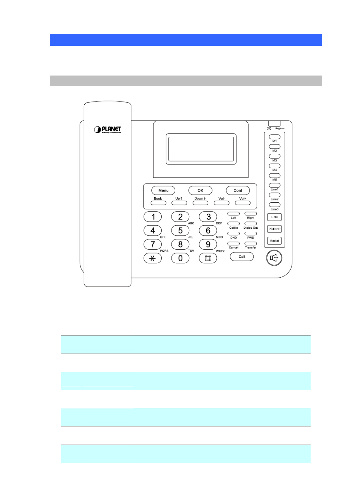
The following figure illustrates the front/rear panel of IP Phone.
Front View and Keypad function
Keypad Description
1 LCD Display
2 Menu
3 OK
4 Conf
5 Book
6
7 Vol + / -
Up↑/ Down↓
Front Panel of VIP-254NT
Menu and all status shall be displayed for users.
To bring out the menu selection while IP Phone is in idle state.
To be used as confirm configuration or enter sub-menu.
Press this button can make conference function.
Enter the phone book selection.
To move the sub-menu selection.
To adjust the volume.
8
Page 9

8 Left / Right
To be used as
9 Call In
10 Dialed Out
11 DND
12 FWD
13 Cancel
14 Transfer
15 Call
16 M1~M5
17 Line 1 ~ Line 3
To check Incoming call
To check dialed call
Enable/Disable the DND function.
To carry out forward function.
To delete the dialing digit
To transfer an active call (incoming call answered or outgoing call
accepted) to another devices.
To sent out the dialing numbers.
Users could store their commonly used number in these keys, and
To make 3 line accounts dial call by pressing the Line1 ~ Line 3.
call them as speed dial
18 Hold
19 PSTN / IP
20 Redial
21 Hand Free
Rear View
To hold the conversation.
To switch between IP and PSTN calls.
Press to dial the last dialed number when the IP Phone is
off-hooked.
To switch between the usage of the handset and the speaker
devices.
Rear Panel of VIP-254NT
9
Page 10

1 DC
2 PC
3 LAN
4 PSTN
7.5~12V DC Power input outlet
RJ-45 connector, to maintain the existing network structure,
connected directly to the PC through straight CAT-5 cable
RJ-45 connector, for Internet access, connected directly to
Switch/Hub through straight CAT-5 cable.
FXO interface, for connect with PSTN line. Press PSTN/IP button
to switch to PSTN mode.
L
Note
Use only the power adapter shipped with the unit to ensure
correct functionality
10
Page 11
Preparations & Installation
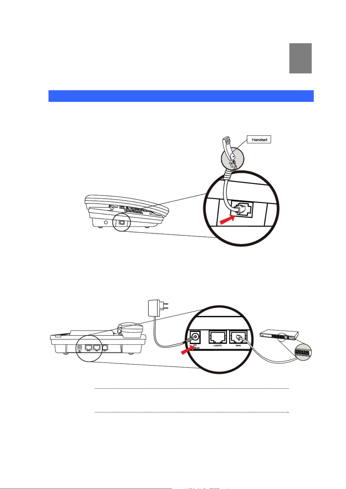
Physical Installation Requirement
Step 1: Handset Connection
Plug Handset Core with Handset and Handset Jack.
Chapter 2
2
Step 2: Connecting Power Adapter and Network
Plug RJ-45 Cable with WAN port and Switch/ Hub
Í
Note
Use only the power adapter shipped with the unit to ensure
correct functionality.
11
Page 12
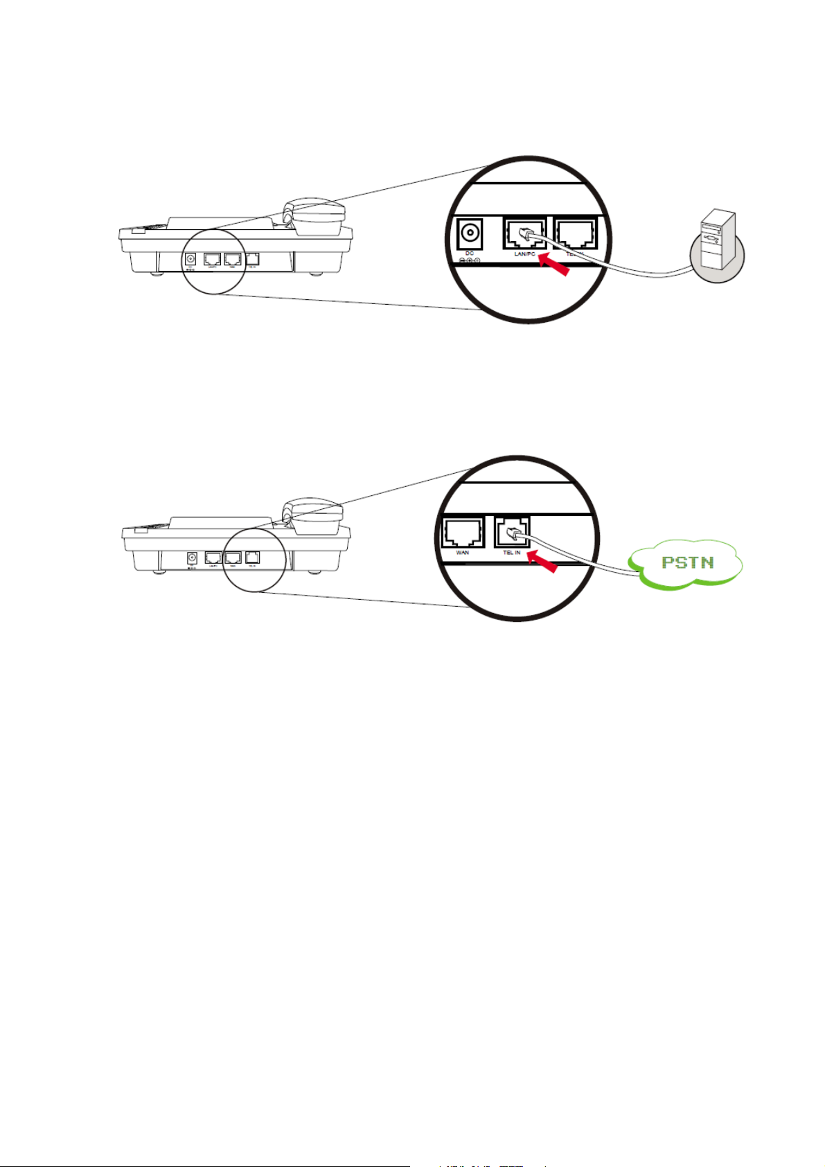
Step 3: Computer Network Setup
Plug RJ-45 Cable with LAN/PC port and Computer
Step 4: Connecting PSTN Line
If there is PSTN line, connect it with TEL IN port
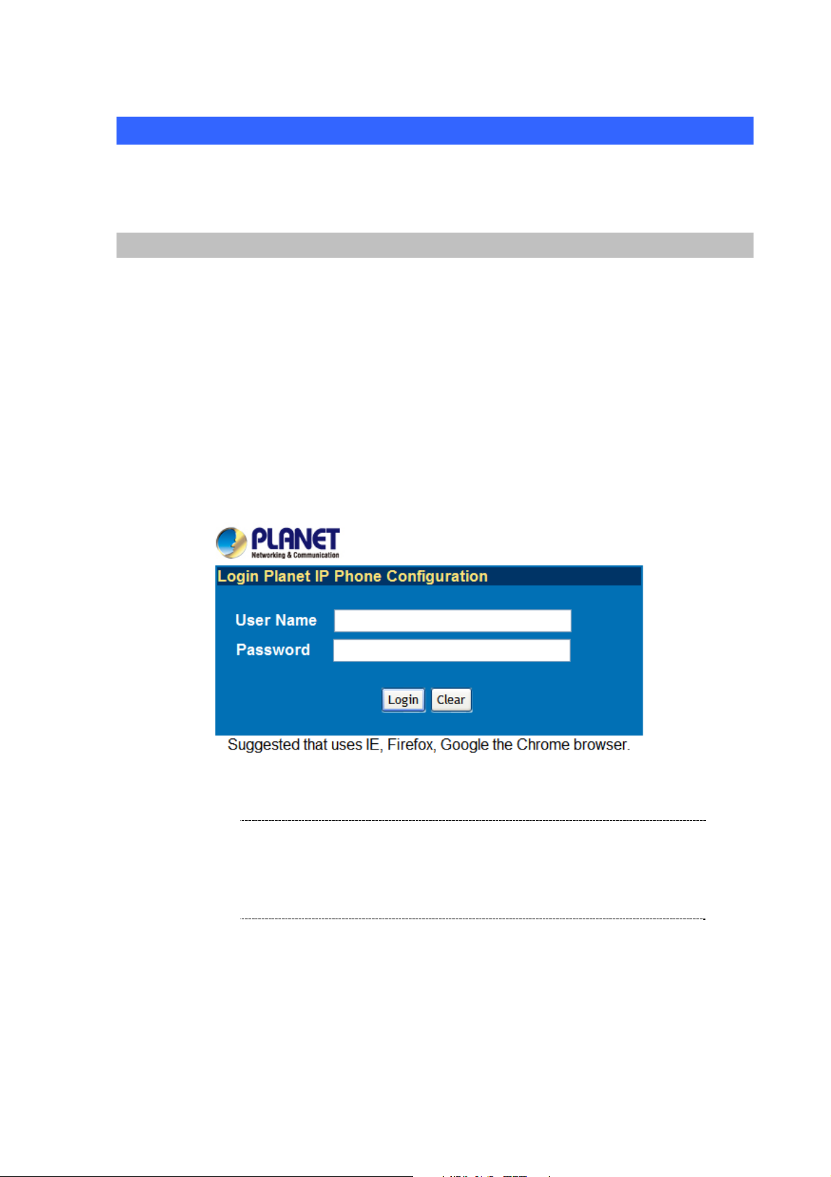
Step 5: Login Prompt
Set your computer’s IP address to 192.168.0.x, where x is a number between 2 to 254 (ex cept 1 where
is being used for the IP Phone by default). If you don’t know how to do this, please ask your network
administrator.Use web browser (Internet Explorer 6.0 or above) to connect to 192.168.0.1 (type this
address in the address bar of web browser). You’ll be prompted to input user name and password: root
/ null (without password).
12
Page 13
Administration Interface
The IP Phone provides GUI (Web based, Graphical User Interface) for machine management and
administration. Key pad administration also available for simple co nfiguration.
Web configuration access:
To start IP Phone web configuration, you must have one of these web browsers installed on computer
for management
• Microsoft Internet Explorer 6.0.0 or higher with Java support
Default IP address of IP Phone is 192.168.0.1. You may now open your web browser, and insert
http://192.168.0.1 in the address bar of your web browser to logon IP Phone web configuration page.
IP Phone will prompt for logon username/password, please ente r: root / null (without password) to
continue machine administration.
In order to connect machine for administration, please
Í
Note
locate your PC in the same network segment (192.168.0.x)
of IP Phone. If you’re not familiar with TCP/IP, please refer
to related chapter on user’s manual CD or consult your
network administrator for proper network configurations.
13
Page 14

Chapter 3
3
Network Service Configurations
Configuring and monitoring your IP Phone from web browser
The IP Phone integrates a web-based graphical user interface that can cover mo st configurations
and machine status monitoring. Via standard, web browser, you can configure and check machine
status from anywhere around the world.
Overview on the web interface of IP Phone
With web graphical user interface, you may have:
More comprehensive setting feels than traditional command line interface.
Provides user input data fields, check boxes, and for changing machine configuration settings
Displays machine running configuration
To start IP Phone web configuration, you must have one of these web browsers install ed on computer
for management
Microsoft Internet Explorer 6.0.0 or higher with Java support
Manipulation of IP Phone via web browser
Log on IP Phone via web browser
After TCP/IP configurations on your PC, you may now open your web browser, and input
http://192.168.0.1
IP Phone will prompt for logon username/password: root / null (without pass word)
to logon IP Phone web configuration page.
IP Phone log in page
When users login the web page, users can see the IP Phone system information like firmware version,
company…etc in this main page.
14
Page 15
IP Phone main page
LAN IP address configuration via web configuration interface
Execute your web browser, and insert the IP address (default: 192.168.0.1) of VIP in the address bar.
After logging on machine with username/password (default: root / without password), browse to
“Network” --> “LAN Settings” configuration menu:
Parameter Description
IP address LAN IP address of
IP Phone
15
Page 16
Default: 192.168.0.1
Subnet Mask LAN mask of
Default: 255.255.255.0
Default Gateway Gateway of
IP Phone
IP Phone
Default: 192.168.0.254
After confirming the modification you’ve done, Please click on the Submit button to apply settings and
browse to “Save & Reboot” menu to reboot the machine to make the settings effective.
Connection Type Data required.
Fixed IP
DHCP client
PPPoE
In most circumstances, it is no need to configure the DHCP
settings.
The ISP will assign IP Address, and related information.
The ISP will assign PPPoE username / password for Internet
access,
L
Hint
Please consult your ISP personnel to obtain proper PPPoE/IP
address related information, and input carefully.
If Internet connection cannot be established, please check
the physical connection or contact the ISP service staff
for support information.
Save Modification to Flash Memory
Most of the IP Phone parameters will take effective after you modify, but it is just temporary stored on
RAM only, it will disappear after your reboot or power off the IP PHone, to save the p arameters into
Flash ROM and let it take effective forever, please remember to press the Save & Reboot button after
you modify the parameters.
16
Page 17
Chapter 4
4
VoIP IP Phone Configurations
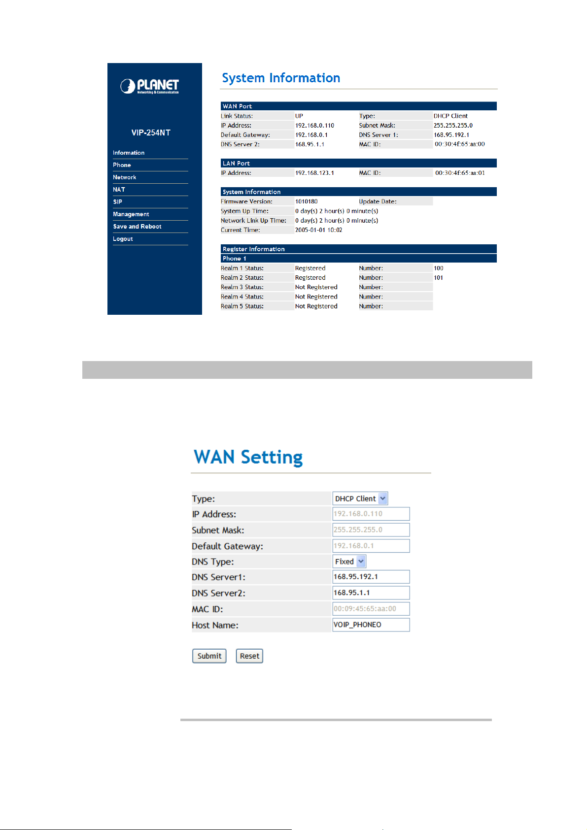
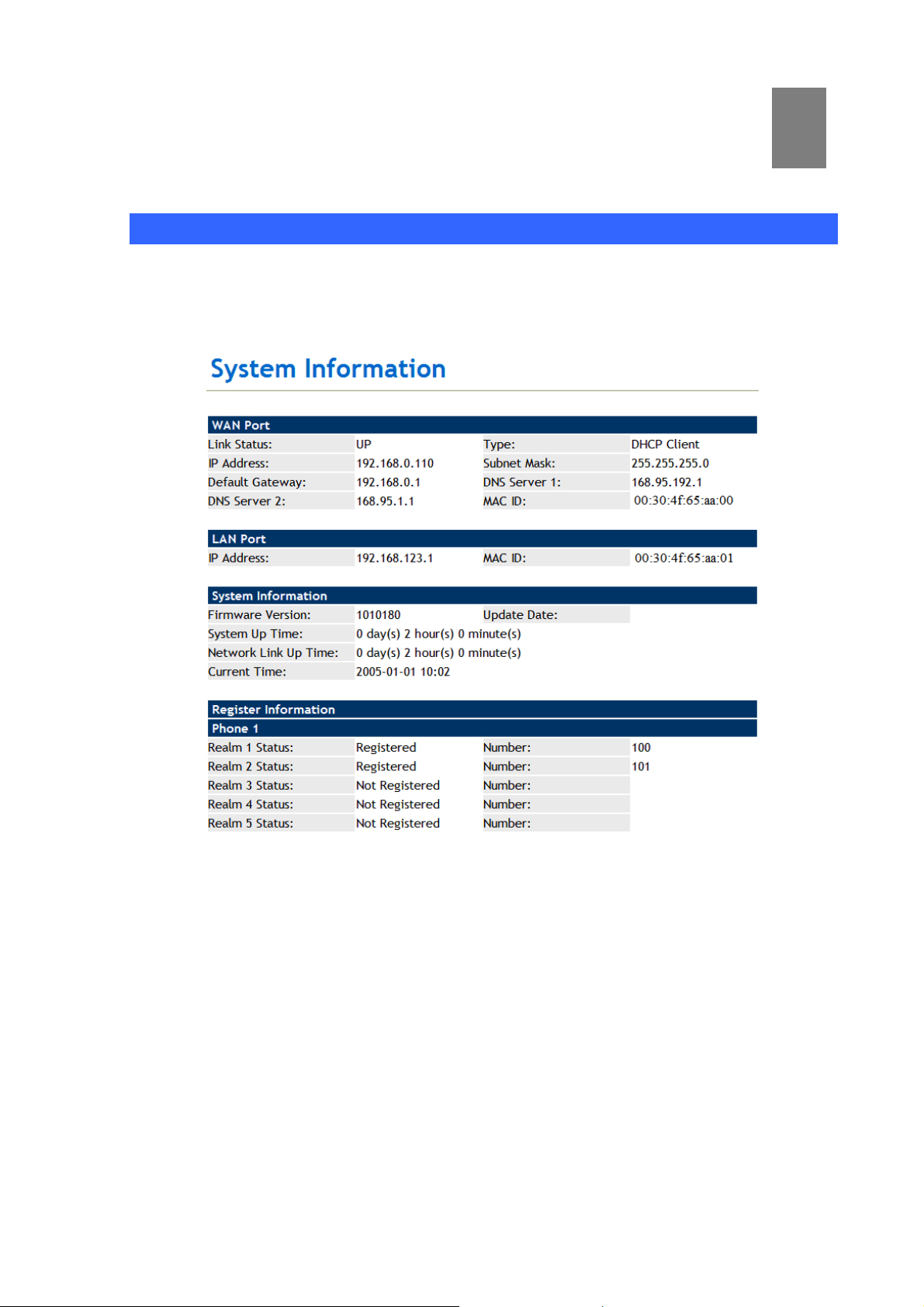
Information
This page shows the major system info rmation; there are WAN Port, LAN Port, System Information and
Register Information. The user could know the network parameters, system firmware version and
register status at this page.
17
Page 18
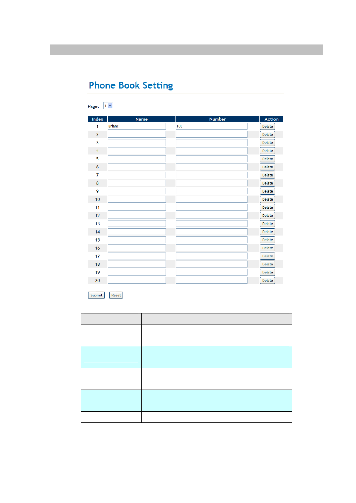
Phone Book settings
IP Phone can set up 140 records of Phone Book. User can make calls via Phone Book feature of IP
Phone.
Field Description
Phone Book Page
Index
Name
Number
Action
If you need to add a phone number into the Phone Book list, you need to input the position, the name,
and the phone number (by URL type ). When you finished a new phone list, just click the “Submit”
button.
The default is Page 1. It can select Page1 ~ Page 7 to
look round Phone Book records.
The record number from 0 ~ 139, it can set up 140
records in total.
The name of Phone Book records, it only can input
numerals.
Fill in the outgoing number (Line Number) or IP
address.
To delete this record.
18
Page 19

If you want to delete a phone number, you can click the “Delete” button at this record.
For Example:
STEP 1:
IP Phone had added the above phone numbers. User press Phone Book button from keypad
then the LCD screen will show below:
Search: [ 3]
STEP 2:
Press OK button to enter the Phone Book menu. The LCD screen will show the Phone Book
records pervious made.
STEP 3:
Selecting the recorder you want to dial and press OK button. It sill show the detail information as
below:
STEP 4:
000 301
001 Brian
202
192.168.0.20:5060
Pick up the telephone handset or press Handfree button to dial to this telephone.
IP Dialing.. 1
192.168.0.20:5062
19
Page 20

Speed Dial settings
In Speed Dial setting fu nction you can add/delete Speed Dial number. The 1~5 records a re available for
M1 ~ M5 Speed Dial buttons, and 6~10 records are reserved at present. You can press the M1 ~ M5
buttons to dial the numbers that set at Speed Dial Setting.
If you need to add a phone number into the S peed Dial list, you need to input the name and the phone
number (by URL type). When you finished a new phone list, just click the “Submit” button.
If you want to delete a phone number, you can click the “Delete” button at this record.
Field Description
Index
Name
Number
Action
Pick Up
Voice Mail
The record number from 1 ~ 10 records.
The name of Speed Dial records.
Fill in the outgoing number (Line Number) or IP
address.
To delete this record.
Fill in the pick-up service digits of SIP Server or IP
PBX. This field is reserved at present.
Fill in the voice mail number of SIP Server or IP PBX.
This field is reserved at present.
20
Page 21

Dial Plan Settings
This page defines the Dial Plan Setting function. This function is when you input the phone number by
the keypad but you don’t need to press “#”. After time out the system will dial directly.
Field Description
Drop Prefix
Rule
+
The rule of add or replace code. If setup as “Disable”, it will add the
prefix number prior to the identification number . If setup as “Enable”, it
will replace the identification number.
The prefix number. It only accept the numeral a nd the max length is 8.
The identification number. It can ac cept the numeral or symbol and
the max length is 40.
- Symbol: It only accept the [+], [x]
21
Page 22

- +: It means as “or”. For example, [123+456+334+5xx] even if [123
or 456 or 334 or 5xx]
- x: It is equal to 0~9. For example, [5xx] even if the number begin
5.
Dial Now
Realm 1~5 prefix
Auto Dial Time
Use # as send key
Auto PSTN backup
If the dialing number are match with this field, it will dial out and need
not to press the “#” key to end the dialing. It accepts the numeral or
symbol, and the max length are 124.
LNote: The starting number ca n’t be the “0”. For example, if the
number is “0xxxx”, because the starting number is “0”, so that the
system will ignore this dial plan.
These options can define the switching code for each Realm No.
Stop dialing after seconds then send dial number out.
If setup as Yes, the system sill stop to receive the dialing number
when receive the [#] key. The system also will to determine the Auto
Dial Time, it will carry out the calling if there isn’t receive the digit after
the Auto Dial Time.
If setup as No, the system just according to the Auto Dial Time to
determine the end time.
Disable Auto PSTN backup options for the phone default. When
you set Enable Auto PSTN backup,if the phone registration failed,then
the phone is automatically switched PSTN-side. So that you can hear
tone from PSTN when pick up the handset.
PSTN feature code
Routing Type
Routing rule
Besides press the “PSTN / IP” button, it also could dial this number will
switch from IP to PSTN mode.
To select use IP or FXO types for auto routing function, and according
to the Routing rule to handle the dialing numbers.
The rule can delete the prefix number.
Descriptions of example:
Example_1: Routing to: FXO, Routing rule: 007+009
1. If the dialing number is “00722199518”, it will send the full number for dialing out via FXO port.
The real dialing number is [00722199518].
2. If the dialing number is “00922199518”, it will send the full number for dialing out via FXO port.
The real dialing number is [00922199518].
Example_2: Drop prefix: No, Replace rule 1: 002, +: 1234+4321 (No limit the digit length)
1. If the dialing number is start as “1234”, it will add the 002 at begi n. The real dialing number is
[0021234…].
2. If the dialing number is start as “4321”, it will add the 002 at begi n. The real dialing number is
[0024321…].
22
Page 23

Example_3: Drop prefix: Yes, Replace rule 2: 006, +: 002+003+004 (No limit the digit length)
1. If the dialing number is start as “002”, it will replace 002 by 006. The real dialing number is
[006…].
2. If the dialing number is start as “003”, it will replace 003 by 006. The real dialing number is
[003…].
Example_4: Drop prefix: No, Replace rule 3: 007, +: 5xxx+35xx (Has limit the digit length)
1. If the dialing number start as “5” and follow 3 digits, it will add the 007 at begin. The real
dialing number is [0075xxx].
2. If the dialing number start as “35” and follow 2 digits, it will add the 007 at begin. The real
dialing number is [00735xx].
Example_5: Dial Now: *xx+#xx+11x+xxxxxx
1. If the dialing number is match with the rule of “*xx”, it will send out the dialing number directly.
For example, *00/ *01/ *02…*99.
2. If the dialing number is match with the rule of “#xx”, it will send out the dialing number directly.
For example, #00/ #01/ #02…#99.
3. If the dialing number is match with the rule of “11x”, it will send out the dialing number directly .
For example, 111/ 112/ 113…119.
4. If the dialing number is match with the rule of 8 digits, it will send out the dialing number
directly. For example, 12345678.
L
Note
If enable the Routing function and the dialing number is
match with Routing rule, machine will carry out the Routing
function and to skip over the below Drop prefix and Replace
rule functions.
23
Page 24

Call Service Settings
You could setup the Call Forward, Hotline, DND and Alarm functions at this page.
Field Description
Call Forward Settings
All All incoming call will forward to the number you chosen.
Forward T ype
Forward Number
Rings
Hotline Settings
Hotline Type
Busy If you are on the phone, the new incoming call will forward
to the number you choosed.
No Answer If you can not answer the phone, the incoming call will
forward to the number you chosen. You have to set the
Time Out time for system to start to forward the call to the
number you choosed.
Busy or No
Answer
All to PSTN All incoming call will forward to the PSTN number.
No Answer of
PSTN
Fill in the forward number.
When assign No Answer forward type, the phone will forward to desired
number when exceed this ring count.
To enable or Disable the hotline function.
If you are on the phone or can not answer the phone, the
incoming call will forward to the number you chosen.
If you can not answer the phone, the incoming call will
forward to the PSTN number.
Hotline Number
DND Settings
DND Type
When you set hotline number and Enable, on the off-hook state auto dialing
your already set hotline number .
If set up as “Enable”, the outside caller can’t cll to this phone at the specific
24
Page 25

time.
DND
Alarm Settings
Alarm Type
Alarm Time
It can set up the disturb t time, 0:0 to 0:0 stand for all the time.
If set up as “Enable”, the phone will ringed up at the specific time.
It can set up the system prompt time with 24 hours.
General Setting
You could setup the Volume, Ringer Type and Auto A nswer functions at this page.
Field Description
Handset Volume
Handset Gain
Speaker Volume
Speaker Gain
Ringer Volume
Ringer Type
PSTN-Out Volume
PSTN-In Gain
Call Waiting
To set the volume for you can hear from the handset.
To set the volume send out to the other side’s handset.
To set the volume for you can hear from the speaker.
To set the volume send out to the other side’s handset via MIC.
To set the ringer volume.
The user can set the tinkle of bells when someone ring your Phone. To
select the Ringer Type you wanted. There are four Ringer Types can
be chosen.
To set the PSTN volume for you can hear.
To set the volume send out to the other side’s handset.
When you are talking with other people, You can choose If you want to
hear the notice when there is a new coming call. If the call waiting
function is On, if there is a new incomeing call, you will hear the call
waiting notice in your current call. If you set the function to Off, then
25
Page 26

you will not hear any notice.
Please notice that this option must be disable when want to use the
Auto Answer function.
Auto Answer
Auto Answer
Counter
PIN Code
PIN Code Number
There are different incoming call types for flexable applications. The
Trunk Gateway function needs to arrange in with the registered
Server System. The 3-Party subscribers could make Off-Net call
(PSTN) through the PSTN port of VIP-254NT.
To set after the ring count met the number you set then the auto
answer will enable.
If you have set the PIN code, the caller will hear a tone to inform to
input the PIN Code then the caller can dial out. Please notice that the
PIN Code function couldn’t function with T runk Gateway function
together.
The PIN code for auto answer protection.
WAN Settings
This page defines the WAN setting in this page.
Field Description
Type
IP Address
The default is Fixed IP, and it also provides DHCP Client and PPPoE
connection modes.
To set the IP address
- Fixed IP: It could setup the IP address manual.
- DHCP Client: It will acquire the IP address automatically.
- PPPoE: It will use the PPPoE connection method.
26
Page 27

Subnet Mask
To set the subnet address
Default Gateway
DNS Type
DNS Server 1
DNS Server 2
MAC ID
Host Name
To set the default gateway address
The default is Fixed mode, it could setup the DNS mode to manual or
auto detection.
It could setup the first DNS server address.
It could setup the second DNS server address.
The MAC of WAN port
The product model
DDNS Settings
This page defines the DDNS setting in this page. You need to have the DDNS account and input the
informations properly. You can have a DDNS account with a public IP address then others can call you
via the DDNS account. But now most of the VoIP applications are work with a SIP Proxy Server. When
you finished the setting, please click the Submit button.
27
Page 28

VLAN Settings
This page defines the VLAN setting in this page. This function needs to co-operate with network
devices which have VLAN function.
Field Description
VLAN Packets
VID (802.1Q/TAG)
User Priority
(802.1P)
CFI
If setup as “Enable”, it could receive VLAN messages.
Dispose VLAN ID is add a Tag header after realize enable the VLAN
function. The realized voice packets transfer at the same VLAN. The
prerequisite is it must the same as VLAN of upper switch. The value
range are 2~4094.
To setup the user priority.
To indicate the Canonical Format.
- If CFI=1, it means the header label include RIF field, and the
NCIF flag valus of RIF will to decide the MAC address is
Canonical Format or Non-Canonical Format in frame information.
- If CFI=0, it means the header label does not include RIF field, and
the MAC address is Canonical Format in frame information.
28
Page 29

VPN (PPTP & L2TP) Settings
The IP Phone has support PPTP and L 2TP VPN cli ent connectio ns, the use could choose the VPN type,
and input the authorization accounts for VPN connection in this page.
SNTP Settings
This page defines the primary and second SNTP Server IP Address, to get the date/time information.
Also you can base on your location to set the Time Zone, and how long need to synchronize again.
When you finished the setting, please click the Submit button.
29
Page 30

NAT Settings
This page defines the PC setting in this page.
Field Description
LAN Mode
LAN IP Address
LAN MAC ID
DHCP Server Active
Assign IP
Lease Time
The default is Bridge mode, and it also provides NAT mode.
The IP address of LAN port. (In the Bridge mode, the Default IP:
192.168.123.1)
The MAC of LAN port
It will allot the IP address automatically when enabke this function.
Start and end IP of lease table. Network device connecting to the
LAN port can dynamic obtain the IP in the range between start IP
and end IP
DHCP server lease time
- Bridge: When set as is mode, the WAN and LAN ports are in
the same network segment.
- NAT: The WAN and LAN ports are in the different network
segment, and LAN port could enable the DHCP Server function
to allot the IP address.
30
Page 31

DMZ Settings
This page defines the DMZ setting in this page.
Field Description
DMZ Type
Assigned IP Addre ss
MAC Clone T ype
If setup as Enable, all of packets (expect SIP packets) will send to
the specific IP address.
The DMZ host IP address.
This function will copy the MAC address from NIC (Network Interface
Card) which placed in PC to LAN port of ATA. That because some
ISP will limit the MAC address for PPPoE dial-up connection.
Virtual Server
This page defines the Virtual Server setting in this page. You could define 24 virtual service information
in this page. When you finished the setting, please click the Submit button.
31
Page 32

Field Description
Index
Enable
Protocol
Internal Port
External Port
Server IP
Action
The serial number. There are total 12 records from Num 1 to 12.
The activate status. The default is Disable, this record will been
activate if enable.
The TCP or UDP com munication protocol.
For corresponding the internal port.
For corresponding the external port.
To input the Server IP address.
To delete this record.
Service Domain Settings
This router comes with the built-in firewall based on the advanced technology of Stateful Packet
In Service Domain Function you need to input the account and the related informations in this page,
please refer to your ISP provider. You can register three SIP accou nt in the Phon. You can dial the V oIP
phone to your friends via first enable SIP account and receive the phone from these three SIP
accounts.
First you need click Active to enable the Service Domain, then you can input the following items.
If you have more than one SIP account, you can following the steps to regi ster to the other ISP.
When you finished the setting, please click the Submit button.
32
Page 33

Field Description
Display Name
Phone Number
Authentication ID
Authentication Password
Domain Server
Proxy Server
Outbound Proxy
Subscribe for MWI
LNote
:
IP Phone can register to three different SIP Proxies at the same time. It can receive any one of
different SIP accounts inco ming call, and it can switch to any one SIP accounts for making calls
through input the switch code. You also could modify the Realm Prefix code at Dial Plan Setting
You can input the name you want to display.
You need to input the Phone Number get from your ISP.
You need to input the Authentication ID get from your ISP.
You need to input the Register Password get from your ISP.
You need to input the Domain Server get from your ISP.
You need to input the Proxy Server get from your ISP.
You need to input the Outbound Proxy get from your ISP. If your
ISP does not provide the information, then you can skip this item.
The device sends a Subscribe packet to the server to subscribe
Message waiting, the device will send a Subscribe packet to the
server after registration.
.
Realm Prefix Code:
1*
For example: The default is realm 1, input the
the telephone set. It will switch to realm 2, and it can make the SIP calls via realm 2.
: Realm 1
2*
: Realm 2
3*
: Realm 3
4*
: Realm 4
5*
: Realm 5
2*
(Follow by the # key) from keypad and hang up
33
Page 34

Codec Settings
This page defines the Codec priority, RTP packet length, and VAD function in this page. You need to
follow the ISP suggestion to setup these items. When you finished the setting, please click the Submit
button.
The user also could defines the Codec ID at thie page. Sometimes 2 VoIP devices with different Codec
ID will cause the interoperability issue. If you are talking with others got some problems, you may ask
the other one what kind of Codec ID he use then you can change your Codec ID. When you finished
the setting, please click the Submit button.
34
Page 35

Advanced Settings
This page defines the Hold by RFC, Voice/SIP QoS and other settings in this page. To change these
settings please following your ISP information. When you finished the setting, please click the Submit
button.
Field Description
SIP Expire Time
SIP Expire Time Mode
SIP Register Retry Interval
SIP T1
SIP T2
SIP Timer B, F, H
To setup the registration interval time.
To setup if cut down the original registration interval time.
If the device register fail, to setup the next retry interval time.
Timer, a timer H = 64 x T1 seconds for all transfers at the
“Completed” state, it decides when server transation cancels
resending response.
SIP session T2 used with T1
The value is 64 x T1
B: INVITE transaction timeout timer
F: Non-INVITE transaction timeout timer
35
Page 36

H: Wait time for ACK receipt
SIP Port Range of Phone 1
RTP Port Range of Phone 1
Hold by RFC
DTMF Mode
RPort
Voice QoS (Diff-Serv)
SIP QoS (Diff-Serv)
Use DNS SRV
Send Keep Alives Pcaket
To assign different SIP port range for ISP provider.
To assign different RTP port range for ISP provider.
The default is disable, and to start up communication hold back
function (RFC definition). Set enable to start up the Hold by RFC
function.
You can setup the InBand DTMF, RFC 2833 Out-Band or SIP
Info DTMF in this page.
A prarmeter used for through registration.
The Voice QoS feature.
The SIP QoS feature. The QoS setting is to set the voice
packets’ pri ority. If you set the value higher than 0, then the voice
packets will get the higher priority to the Internet. But the QoS
function still need to cooperate with the others Internet devices.
The default is disable, and use DNS SRV mode. Set enable to
use DNS to SRV mode to search the host information.
To deliver the packets on a regular time schedule to keep NAT
port could open continued.
Keep Alives Period
Jitter Buffer
SIP Server type
To setup the schedule time for delivering the packets.
To setup the Jitter Buffer size, and the unit is packet. It needs to
refer to the Frame size of Codec.
To setup the SIP Server type.
STUN settings
This page defines the STUN Enable/Disable and STUN Server IP address in this page. This function
can help your IP Phone working properly behind NAT. To change these settings please following your
ISP information. When you finished the setting, please click the Submit button.
36
Page 37

Auto Configuration Setting
This page defines the Auto Configuration (Auto Provision) setting. IP Phone supports TFTP, FTP, HTTP
function in total.
37
Page 38

Auto Update Setting
The device can update new firmware with the gz or ds file format automatically by the Auto Update
function.
Field Descriptions
Type
TFTP Server
TFTP File Path
HTTP Server
HTTP File Path
FTP Server
FTP User Name
FTP Password
FTP File Path
There are TFTP/ FTP and HTTP three ways to provide the auto
update function.
Input the TFTP Server address, and it could input the IP or Domain
Name form.
Set up the file path.
Input the HTTP Server address, and it could input the IP or Domain
Name form.
Set up the file path.
Input the FTP Server address, and it could input the IP or Dom ain
Name form.
The login username.
The login password
Set up the file path.
38
Page 39

Check new firmware
The device will according to the below ways to check the new
firmware.
- Power On and Scheduling: The machine will check the new
firmware when power on and following the scheduling date
and time.
- Scheduling only: The machine will only follow the scheduling
date and time to check the new firmware.
Scheduling (Date)
Scheduling (Time)
Automatic Update
Firmware File Prefix
Next update time
LNote:
If the Check new firmware field selected to Power On, the machine will chck the new
firmware accoeding the scheduling time/date and power on. If there are new firmware can
The machine will check the new firmware between the date range
by random.
The machine will check the new firmware between the time range
by random.
There are Notify only and Automatic ways to update.
- Notify only: If there are new firmware, the IP Phone will send
the “Be Be Be” sounds when pick up the handset to prompt
there are new firmware.
- Automatic: The device will carry firmware update out
automatically.
It will check the information of model name.
It will show the next check date and time.
be upgraded, the machine won’t carry firmware update out automatic. The machine will
show the [Found New s/w] message on LCD. Then press [Menu] button for entrying the
main menu and select the [7.Administrator -> 2. Upgrade System -> 1.Upgrade Now]
selection to carry out the upgrade firmware action.
Update Firmware
In Update Firmware function you can update new firmware via HTTP method in this page. You can
ugrade the firmware by the following steps:
Select the upgrade method and the firmware code type, SSH code.
Click the “Browse” button in the right side of the File Location or you can type the correct path and the
filename in File Location blank.
Select the correct file you want to download to the device then click the Update button.
39
Page 40

LNote
:
1. After firmware loaded, the unit will be reboot, and Default IP address of the customized
firmware: http://192.168.0.1
2. If the firmware file format is .ROM type, please insert http://IP Phone
address/update.htm in the address bar. Then select "All ROM" type to update
firmware.
; login name/password: root /null (no password)
Advanced Settings
This page defines the advanced functions. When you finished the setting, please click the Submit
button.
40
Page 41

Field Descriptions
ICMP Not Echo
Auto Answer Call
Send Anonymous CID
Management from WAN
Stop Feature Tone
IP Dialing Format
Send Flash Event
Encryption Type
This function can disable echo when someone ping this device,
it can avoid haker try to attack the device.
When you set Enable auto answer call, Answering from all
incoming call. ( Auto open MIC )
If enable this function, machine will to start the calling hidden
function, and it will not send the related Caller information. (The
Registration Server also need support this function)
If enable this function, only WAN be able to connect to the
management GUI
When you set Disable stop feature tone, you can hear Tone
with already subscribe for MWI, Forward, DND...ect from
handset
To setup the IP dialing type when making call by Peer-to-Peer
mode.
There are provide two flash formats: DTMF Event and SIP Info.
There are provide seven encrypt formats: INFINET, AVS,
WALKERSUN1, WALKERSUN2, CSF1, CSF2, GX and VGX.
(The Registration Server also need support this function)
41
Page 42

Encryption Key
The encryption key is use to authentication data transmitted in
the SIP network.
PPPoE Retry period
System Log Server
System Log Type
FXO Port Country
FXO Silence Timeout
FXO CID forward
Generate Flash Signal
for FXO
NET Bandwidth Limit
If PPPoE dial-up connection fail, machine will retry the dial-up
motion after this time.
Machine could send the system logs to the specific Syslog
Server. It can input the IP or Domain address.
There are seven Syslog types: Call Statistics, General Debug,
Call Statistics + General Debug, SIP Debug, Call Statistics +
SIP Debug, General Debug + SIP Debug and All.
To setup the country for FXO port.
When there is no conversation at FXO port exceed this time,
this call will be closed by IP Phone.
When the outside PSTN caller make On-Net call to another SIP
user, to decid e if forward the outside PSTN caller ID to the
called party.
To setup the flash time for FXO port.
To decide the network bandwidths.
Password Setting
In this page, you can change the login username and password for different user levels.
42
Page 43

Tone Settings
This page defines the Tone settings. This function can setup the related parameters of Dial Tone, Ring
Back Tone, Busy T one, Er ror Tone and Insert Tone. When you finished the setting, please click the
Submit button.
Restore Default Setting
In Default Setting you can restore the IP Phone to factory default in this page. You can just click the
Restore button, then the IP Phone will restore to default and automatically restart again.
Language Setting
In this page, you could choice different language for Web UI. The IP Phone will reboot automatically to
effect the new language.
43
Page 44

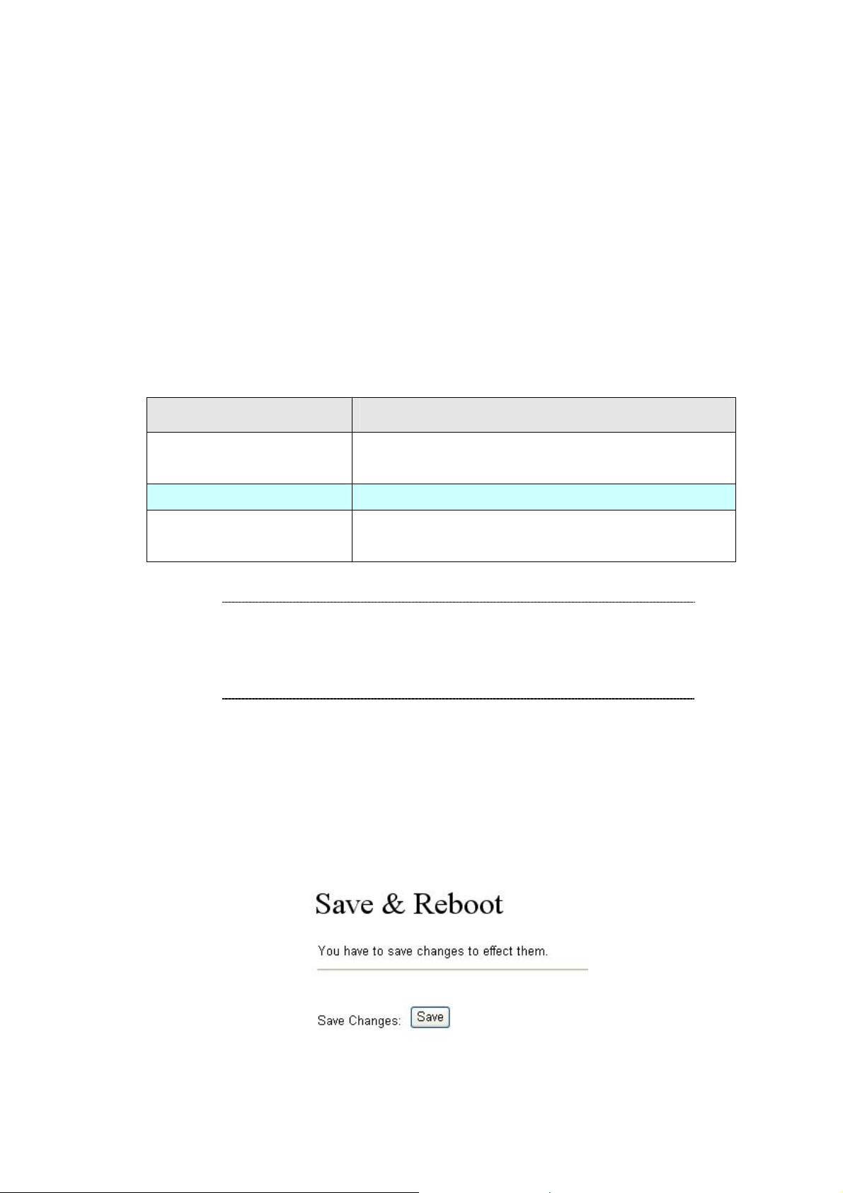
Save & Reboot
In Save & Reboot you can save the changes you have done. If you want to use new setting in the IP
Phone, you have to click the Save button. Af ter you click the Save button, the IP Phone will
automatically restart and the new setting will effect.
If you want to restart the IP Phone, you can just click the Reboot button, then the IP Phone will reboot
automatically.
Logout
To logout Web Management interface via this funciton.
44
Page 45

Appendix A Voice communications
There are several ways to make calls to desired destination in IP Phone. In this section, we’ll lead you
step by step to establish your first voice communication via keypad and web browsers op erations.
Case 1: Voice communication via SIP IP PBX _IPX-300
VIP-254NT-A
LAN IP Address
(192.168.0.1)
Number: 100 Number: 200
VIP-254NT-B
LAN IP Address
(192.168.0.2)
Machine configuration on the VIP-254NT:
STEP 1:
Log in SIP-50 and create two testing accounts/password: 100 / 123 (for VIP-254NT-A), and
200 / 123 (for VIP-254NT- B) for the voice calls.
STEP 2:
Please log in VIP-254NT-A via web browser, browse to the SIP setting menu and select the
Domain Service config menu. In the setting page, please insert the account/password
information obtained from your service provider (in this sample, we’re using PLANET SIP-50
as the SIP Proxy server for SIP account, call authentications), and then the sample
configuration screen is shown below:
IPX-300
WAN IP Address
(192.168.0.50)
45
Page 46

STEP 3:
STEP 4:
Repeat the same configuration steps on VIP-254NT-B, and check the machine
registration status, make sure the registrations are completed.
To verify the VoIP communication, please pick up the telephone. Di al the destination numbe r
to make call between SIP clients. For example, VIP-254NT-A (with number 100) with keypad
number 200 to VIP-254NT- B, or reversely makes calls from SIP client (VIP-254NT-B) to the
number 100 (VIP-254NT-A).
Case 2: Call Forward Feature_IP to IP Forward
In the following samples, we’ll introduce the Call Forward Feature applications.
In this example, there are three VIP-254NT register to IPX-300 and VIP-254NT_A had set Call Forward
function to VIP-254NT_B. (The detail registration settings of IPX-300 and VIP-254NT ple ase refer to
the instruction of Case 3)
46
Page 47

VIP-254NT_A
VIP-254NT_B VIP-254NT_C
Machine configuration on the VIP-254NT:
STEP 1:
Please log in VIP-254NT_A via web browser, brow se to the Phone Settings menu and
select the Call Service config menu. In the setting page, please enable the All Forward
function and fill the number of VIP-254NT_B in the Forward Number field, then the sample
configuration screen is shown below:
STEP 2:
After set up completed and reboot machine, the LCD screen will show below:
10-19 17:20
AF 2002
Test the scenario:
1. VIP-254NT_C pick up the telephone
2. Dial the number 1001(VIP-254NT_A)
3. Because VIP-254NT_A had set up All forward function to the Number 2002 (VIP-254NT_B)
4. The number 2002(VIP-254NT_B) will ring up then it pick up the telephone and communication
with the number 3003(VIP-254NT_C).
47
Page 48

Case 3: Call Forward Feature_All to PSTN
In this example, there are one VIP-254NT which connected with PSTN line, and the other two
VIP-254NT register to IPX-300. The VIP-254NT_A had set Call Forward function to phone number
1111-2222 (PSTN).
Machine configuration on the VIP-254NT_A:
Please log in VIP-254NT_A via web browser, brow se to the Phone Settings menu and select the
Call Service config menu. In the setting page, please select the All to PSTN function and fill the
11112222 (PSTN Phone Number) in the Forward Number field, then the sample configuration
screen is shown below:
Test the scenario:
1. VIP-254NT_C pick up the telephone
2. Dial the number 1001(VIP-254NT_A)
3. Because VIP-254NT_A had set up All to PSTN forward function to the PSTN Phone Number
11112222
4. The PSTN Phone Number 11112222 will ring up then it pick up the telephone and
communication with the number 3003(VIP-254NT_C)
48
Page 49

Case 4: Call Forward Feature_PSTN to IP Forward
In this example, there are three VIP-254NT register to IPX-300. The VIP-254NT_A had set Call
Forward function to number 2002 (VIP-254NT_B).
Machine configuration on the VIP-254NT_A:
Please log in VIP-254NT_A via web browser, brow se to the Phone Settings menu and select the
Call Service config menu. In the setting page, please enable the All Forward function and fill the
number of VIP-254NT_B in the Forward Number field, then the sample configuration screen is
shown below:
Test the scenario:
1. PSTN Phone Number 11112222 pick up the telephone
2. Dial the PSTN Phone Number 33334444(VIP-254NT_A)
3. Because VIP-254NT_A had set up All forward function to the Number 2002 (VIP-254NT_B)
4. The number 2002(VIP-254NT_B) will ring up then it pick up the telephone and communication
with the PSTN caller.
49
Page 50

Case 5: Call Forward Feature_Peer to Peer mode
In this example, there are three VIP-254NT and connect with Peer to Peer mode . VIP-254NT_A had set
Call Forward function to VIP-254NT_B.
Machine configuration on the VIP-254NT_A:
Please log in VIP-254NT_A via web browser, brow se to the Phone Settings menu and select the
Call Service config menu. In the setting page, please enable the All forward function and fill the IP
address of VIP-254NT_B in the Forward Number field, and then the sample configuration screen
is shown below:
Test the scenario:
1. VIP-254NT_C pick up the telephone
2. Dial the IP Address 192.168.0.1(VIP-254NT_A)
3. Because VIP-254NT_A had set up All forward function to the IP Address 192.168.0.2
(VIP-254NT_B)
4. The IP Address 192.168.0.2 (VIP-254NT_B) will ring up then it pick up the telephone and
communication with the VIP-254NT_C
Case 6: Auto Answer Feature_IP to PSTN
In this example, there are three VIP-254NT and connect with Peer to Peer mode. The VIP-254NT_A
had set Auto Answer function for forwarding calls to arbitrary telephone. If there have incoming IP calls
and VIP-254NT_A d oesn’t answer the incoming calls after specific time, the caller will hear prompt
sounds to input the password then dial out an arbitrary PSTN telephone.
50
Page 51

Machine configuration on the VIP-254NT:
STEP 1:
Please log in VIP-254NT_A via web browser, brow se to the Phone Settings menu and
select the Call Service config menu. In the setting page, please disable All Forward
STEP 2:
function, and then the sample configuration screen is shown below:
Please log in VIP-254NT_A via web browser, brow se to the Phone Settings menu and
select the General config menu. In the setting page, please disabl e the Call Waiting at first,
then choose Both option for Auto Answer function, and enable the PIN Code function, then
the sample configuration screen is shown below:
51
Page 52

Test the scenario:
1. VIP-254NT_C pick up the telephone
2. Dial the IP Address 192.168.0.1(VIP-254NT_A)
3. VIP-254NT_A will ring up but doesn’t answer the call
4. After 3 rings, the VIP-254NT_C will hear the prompt sounds then input the password 123#
5. VIP-254NT_C will hear the dial tone from PSTN line then input Phone Number 11112222
6. The Phone Number 11112222 will ring up then it pick up the telephone and communication with
the VIP-254NT_C
Case 7: Auto Answer Feature_PSTN to IP
In this example, there are three VIP-254NT register to IPX-300. The VIP-254NT_A had set Auto
Answer function for forwarding to arbitrary telephone. If there have incoming PSTN calls and
VIP-254NT_A doesn’t answer the incoming calls after specific time, the caller will hear prompt sound s
to input the password and then dial out an arbitrary IP telephone.
52
Page 53

Machine configuration on the VIP-254NT:
Please log in VIP-254NT_A via web browser, brow se to the Phone Settings menu and select the
General config menu. In the setting page, please choose Both option for Auto Answer function,
and enable the PIN Code function, then the sample configuration screen is shown below:
Test the scenario:
1. The Phone Number 11112222 pick up the telephone
2. Dial the PSTN Phone Number 33334444(VIP-254NT_A)
53
Page 54

3. VIP-254NT_A will ring up but doesn’t answer the call
4. After 3 rings, the Phone Number 11112222 will hear the prompt sounds then input the
password 123#
5. The Phone Number 11112222 will hear the dial tone then input 2002
6. The VIP-254NT_B will ring up then it pick up the telephone and communication with the Phone
Number 11112222
54
Page 55

Appendix B The method of operation guide
In this section, we’ll introduce the features method of operation, and lead you step by step to establish
these features.
Call Transfer
A. Blind Transfer
1. B call to A and they are in the proces s of conversation.
2. A press “Transfer” button to hold the conversation with B, and input the number of C (Follow
by the “#” key).
3. C will ring up, and A hang up the handset.
4. C picks up the handset and conversation with B.
B. Attendant Transfer
1. B call to A and they are in the proces s of conversation.
2. A press “Transfer” button to hold the conversation with B, and input the number of C (Follow
by the “#” key).
3. C will ring up.
4. C picks up the handset and conversation with A.
5. A hang up and C conversation with B.
3-Way Conference
1. A and B are in the process of conversation.
2. A want to invite C to join their conversation.
3. A press “Transfer” button to hold the conversation with B, and input the number of C (Follow
by the “#” key).
4. C will ring up and pick up the handset to conversation with A.
5. A press “Conf” button and they will entry the 3-Way conference mode.
Call Waiting
1. A and B are in the process of conversation.
2. C call to A and A will hear the prompt sounds.
3. A press “Hold” button to hold the conversation with B, and switch to conversation with C.
Switch the Realm (Registration Proxy Server)
IP Phone can register to three different SIP Proxies at the same time. It can receive any one of different
55
Page 56

SIP accounts incoming call, and it can switch to any one SIP accounts for making calls through input
the switch code.
Realm switch code:
1*
For example: The default is realm 1, input the
telephone set. It will switch to realm 2, and it can make the SIP calls via realm 2.
: Realm 1
2*
: Realm 2
3*
: Realm 3
4*
: Realm 4
5*
: Realm 5
2*
(Follow by the # key) from keypad and hang up the
56
Page 57

Appendix C VIP-254NT Specifications
Product SIP IP Phone with PSTN support
Model VIP-254NT
Hardware
WAN 1 x 10/100Mbps RJ-45 port
LAN 1 x 10/100Mbps RJ-45 port
LCD display 2 x 16 characters
Speaker Full duplex hands free speaker phone
Protocols and Standard
Standard SIP 2.0 (RFC3261), MD5 for SIP authentication (RFC2069/ RFC 2617), SIP
outbound proxy, SIP NAT Traversal Support STUN (RFC3489)
Voice codec G.711: 64k bit/s (PCM)
G.723.1: 6.3k / 5.3k bit/s
G.726: 16k / 24k / 32k / 40k bit/s (ADPCM)
G.729A: 8k bit/s (CS-ACELP)
G.729: 8k bit/s
Voice Standard Voice activity detection (VAD)
Comfort noise generation (CNG)
Acoustic echo canceller (AEC)
G.165: Line echo canceller (LEC)
Jitter Buffer
Supplementary services Caller ID
3-way conference
Immediate (unconditional) call forwarding
Busy call forwarding
No answer calls forwarding
Call Hold/Waiting/Transferring
Call history Record incoming call
Outgoing call
Missed (not accepted) call history
Protocols SIP v1 (RFC2543), v2(RFC3261), TCP/IP, UDP/RTP/RTCP, HTTP, ICMP, ARP,
RARP, DNS, DHCP, SNTP, PPPoE
Network and Configuration
Access Mode Static IP, PPPoE, DHCP
Management Web, LCD menu keypad, auto-provision by TFTP/FTP /HTTP
Dimension (W x D x H) 168 x 220 x 60 mm
Operating Environment 0~50 degree C, 0~90% humidity
Power Requirement 7.5~12V DC, 1A
EMC/EMI CE, FCC Class B
57
 Loading...