

Page 1
High Definition Color PoE IP Phone with Dual Display
VIP-2140PT
VIP-2140PT
High Definition Color PoE IP
Phone with Dual Display
1
Page 2

High Definition Color PoE IP Phone with Dual Display
VIP-2140PT
Copyright
Copyright 2016 by PLANET Technology Corp. All rights reserved. No part of this publication may be
reproduced, transmitted, transcribed, stored in a retrieval system, or translated into any language or computer
language, in any form or by any means, electronic, mechanical, magnetic, optical, chemical, manual or
otherwise, without the prior written permission of PLANET.
PLANET makes no r epresentations or warranties , either expressed or im plied, with respect to the co ntents
hereof and specif ically disclaims any warranties, m erchantability or fitness f or any particular purpose. An y
software described i n t his manual is sold or licens ed "as it is". Sh ou ld t he pr ogra ms prove defective f ollo win g
their purchase, the buyer (and not PLANET, its distributor, or its dealer) assumes the entire cost of all
necessary servicing, repair, and any incidental or consequential damages resu lting from any defect in the
software. Further, PLANET reserves the right to revise this publication and to make changes from time to time
in the contents hereof without obligation to notify any person of such revision or changes.
All brand and produc t names mentioned in this m anual are tr adem arks and/or registered tr adem arks of thei r
respective holders.
Federal Communication Commission Interference Statement
This equipment has been t ested and found t o com ply with the lim its for a Class B digit al devic e, pursua nt to
Part 15 of FCC Rules. These limits are designed to provide reasonable protection against harmful
interference in a r esidential installation. This equ ipment generates , uses, and can radiate radio f requency
energy and, if not installed and used in accordance with the instructions, may cause harmful interf erence to
radio communications. However, there is no guarantee that interference will not occur in a particular
installation. If this equipm ent does cause harmf ul interference to radio or telev ision reception, which can be
determined by turnin g the equ ipment off and on, the user is encoura ged to tr y to correct t he inter ference by
one or more of the following measures:
1. Reorient or relocate the receiving antenna.
2. Increase the separation between the equipment and receiver.
3. Connect the equipment into an outlet on a circuit different from that to which the receiver is connected.
4. Consult the dealer or an experienced radio technician for help.
FCC Caution
To assure continued compliance, for example, use only shielded interface cables when connecting to
computer or peripheral devices. Any changes or modifications not expressly approved by the party
responsible for compliance could vo id the user ’s authority to operate the equipment.
This device com plies with Part 1 5 of th e FCC Rul es. Operat ion is subj ect to th e follo wing two co nditions: ( 1)
This device may not cause harmful interference, and ( 2) this device must acc ept any interference received,
2
Page 3

High Definition Color PoE IP Phone with Dual Display
VIP-2140PT
including interference that may cause undesired operation.
Federal Communication Commission (FCC) Radiation Exposure Statement
This equipment com plies with FCC radiati on exposure set forth for an uncontr olled environm ent. In order to
avoid the possibilit y of exceeding the FC C radio frequenc y exposure limits , human proxim ity to the antenna
shall not be less than 20 cm (8 inches) during normal operation.
Safety
This equipment is designed with the utmost care for the safety of those who install and use it. However,
special attention must be paid to the dangers of electric shock and static electricity when working with
electrical equipm ent. All guidelines of this and of the com puter manuf acture must theref ore be allowed at a ll
times to ensure the safe use of the equipment.
CE Mark Warning
This is a Class B product. I n a domestic environment, this prod uct may cause radio interference, in which
case the user may be required to take adequate measures.
WEEE Regulation
To avoid the pote nti al ef f ec ts on th e en viro nment and human hea lt h as a result of the presence of
hazardous substances in electrical and electronic equipment, end users of electrical and electronic
equipment should understand the meaning of the crossed-out wheeled bin symbol. Do not dispose
of WEEE as unsorted municipal waste; they should be collected separately.
Revision
User’s Manual of PLANET High Definition Color PoE IP Phone with Dual Display
Model: VIP-2140PT
Rev: 1.00 (November, 2016)
Part No. EM-VIP-2140PT_v1.0
3
Page 4

High Definition Color PoE IP Phone with Dual Display
VIP-2140PT
Table of Contents
Chapter 1. Product Introduction ................................................................................................................ 10
1.1 Package Contents ......................................................................................................................... 10
1.2 Overview ....................................................................................................................................... 11
1.3 Features ........................................................................................................................................ 14
1.4 Specifications ................................................................................................................................ 16
Chapter 2. Hardware Interface and Installati o n ........................................................................................ 20
2.1 Physical Descriptions .................................................................................................................... 20
2.2 Using Handset/Hands-free Speaker/Headphone ......................................................................... 22
2.3 Desktop and Wall-mount Installation ............................................................................................ 23
Chapter 3. Introduction to the Phone User Interface ............................................................................... 25
3.1 Screen User Interface ................................................................................................................... 25
3.2 Web Portal..................................................................................................................................... 26
Chapter 4. IP Phone Setup .......................................................................................................................... 28
4.1 Network Configuration ................................................................................................................... 28
4.2 Line Configurations ....................................................................................................................... 29
Chapter 5. Using the Phone ........................................................................................................................ 36
5.1 Making Phone Calls ...................................................................................................................... 36
5.2 Make/Receive Second Call ........................................................................................................... 40
5.3 Join/Split Two Calls (3-way Local Conference) ............................................................................ 41
5.4 Call Transfer .................................................................................................................................. 42
5.5 Using Phonebook .......................................................................................................................... 42
5.6 Add/Edit/Delete Contact ................................................................................................................ 45
5.7 Add/Edit/Delete Group .................................................................................................................. 45
5.8 Browse and Add/Remove Contacts in Grou p ............................................................................... 46
5.9 Using Cloud Phonebook ............................................................................................................... 47
5.10 Open Cloud Phonebook ................................................................................................................ 48
5.11 Call Logs ....................................................................................................................................... 49
5.12 Voice Message .............................................................................................................................. 50
5.13 Do-Not-Disturb .............................................................................................................................. 51
5.14 Auto-Answering ............................................................................................................................. 53
5.15 Call Forward .................................................................................................................................. 54
Chapter 6. Phone Settings .......................................................................................................................... 56
6.1 Adjust Audio Volume ..................................................................................................................... 56
4
Page 5

High Definition Color PoE IP Phone with Dual Display
VIP-2140PT
6.2 Set Ring Tone Volume and Type .................................................................................................. 56
6.3 Adjust LCD Contrast ..................................................................................................................... 56
6.4 Set Device Time/Date ................................................................................................................... 57
6.5 Set Device Language .................................................................................................................... 58
6.6 Reboot the Device ......................................................................................................................... 58
6.7 Reset to Factory Default ............................................................................................................... 58
Chapter 7. Web Portal ................................................................................................................................. 59
7.1 Web Portal Authentication............................................................................................................. 59
7.2 Web Call ........................................................................................................................................ 59
7.3 SYSTEM (Information) .................................................................................................................. 60
7.4 SYSTEM (Account) ....................................................................................................................... 61
7.5 SYSTEM (Configurations) ............................................................................................................. 61
7.6 SYSTEM (Upgrade) ...................................................................................................................... 61
7.7 SYSTEM (Auto Provisi on) ............................................................................................................. 61
7.8 SYSTEM (Tools) ........................................................................................................................... 62
7.9 NETWORK (Basic) ........................................................................................................................ 62
7.10 NETWORK (Advanced) ................................................................................................................ 62
7.11 NETWORK (VPN) ......................................................................................................................... 62
7.12 LINES (SIP) ................................................................................................................................... 62
7.13 LINES (Dial Peer) .......................................................................................................................... 66
7.14 LINES (Dial Plan) .......................................................................................................................... 72
7.15 LINES (Global Settings) ................................................................................................................ 73
7.16 PHONE (Features) ........................................................................................................................ 74
7.17 PHONE (Audio) ............................................................................................................................. 76
7.18 PHONE (MCAST) ......................................................................................................................... 78
7.19 PHONE (Time/Date) ..................................................................................................................... 78
7.20 PHONE (Advanced) ...................................................................................................................... 79
7.21 PHONEBOOK (Contacts) ............................................................................................................. 79
7.22 PHONEBOOK (Clou d Pho nebo ok) ............................................................................................... 80
7.23 PHONEBOOK (Blacklist) .............................................................................................................. 81
7.24 PHONEBOOK (Advanced)............................................................................................................ 81
7.25 CALL LOGS .................................................................................................................................. 81
7.26 FUNCTION KEY .......................................................................................................................... 82
7.27 FUNCTION KEY (Softkey) ............................................................................................................ 83
Chapter 8. Advanced Features ................................................................................................................... 84
8.1 VPN ............................................................................................................................................... 84
8.2 L2TP .............................................................................................................................................. 84
5
Page 6

High Definition Color PoE IP Phone with Dual Display
VIP-2140PT
8.3 OpenVPN ...................................................................................................................................... 84
Chapter 9. Troubleshooting ........................................................................................................................ 86
9.1 Get Device System Information .................................................................................................... 86
9.2 Upgrade to the latest software ...................................................................................................... 86
9.3 Reboot Device ............................................................................................................................... 86
9.4 Reset Device to Factory Default ................................................................................................... 86
9.5 Network Packets Capture ............................................................................................................. 87
9.6 Common Trouble Cases ............................................................................................................... 87
Appendix I - Icon Illustration ......................................................................................................................... 89
Appendix II - Text Input from Keypad ........................................................................................................... 91
Appendix III - LED Definition ......................................................................................................................... 93
6
Page 7

High Definition Color PoE IP Phone with Dual Display
VIP-2140PT
Figures
Figure 1 - Keypad ...................................................................................................... 20
Figure 2 - Connecting to the Device.......................................................................... 22
Figure 3 - Desktop Installation .................................................................................. 23
Figure 4 - Wall-mount Installation ............................................................................. 24
Figure 5 - Screen Layout/Def ault Stan dby Screen ................................................... 25
Figure 6 - Vertical Scroll Bar ..................................................................................... 26
Figure 7 - Check the Device’s IP Address ................................................................ 26
Figure 9 - Configure SIP Proxy Server Address ....................................................... 29
Figure 10 - Configure SIP Proxy Server Port ............................................................ 30
Figure 11 - Configure SIP Username ........................................................................ 30
Figure 12 - Configure Authentication Name .............................................................. 30
Figure 13 - Configure SIP Auth ent icati on Pas sword ................................................. 31
Figure 14 - Configure Display Name ......................................................................... 31
Figure 15 - Enable/Disable Outbound Proxy ............................................................ 31
Figure 16 - Enable/Dis abl e SIP Line ......................................................................... 32
Figure 17 - Configure Advanced Line Options .......................................................... 32
Figure 18 - Configure SIP Realm/Domain ................................................................ 32
Figure 19 - Configure Unregistered Dial ................................................................... 32
Figure 20 - Enable/Disable Ano n ymous ................................................................... 33
Figure 21 - Configure DTMF Mode ........................................................................... 33
Figure 22 - Enable/Disable ST U N ............................................................................. 33
Figure 23 - Configure Local Port ............................................................................... 33
Figure 24 - configure Ring Type ................................................................................ 33
Figure 25 - Configure MWI Number .......................................................................... 33
Figure 26 - Configure Pickup Number....................................................................... 34
Figure 27 - Configure Park Number .......................................................................... 34
Figure 28 - Configure Join Call Number ................................................................... 34
Figure 30 - Enable/Disable F eature Sync ................................................................. 34
Figure 31 - Enable/Dis abl e SCA ............................................................................... 34
Figure 32 - Default Line ............................................................................................. 36
Figure 33 - Dialing a Number before Audio Channel Opened .................................. 37
Figure 34 - Dial a Number after Audio Channel Opened .......................................... 37
Figure 35 - Calling Remote Party .............................................................................. 38
Figure 36 - Incoming Call Screen .............................................................................. 38
Figure 37 - Talking Mode Screen .............................................................................. 39
7
Page 8

High Definition Color PoE IP Phone with Dual Display
VIP-2140PT
Figure 38 - Call Holding Screen ................................................................................ 39
Figure 40 - Dual Calls ............................................................................................... 41
Figure 41 - Conference Call ...................................................................................... 41
Figure 42 - Phonebook Screen ................................................................................. 43
Figure 43 - Phonebook is Empty ............................................................................... 43
Figure 44 - Browsing Pho n ebook .............................................................................. 44
Figure 45 - Add New Contact .................................................................................... 45
Figure 46 - Group List ............................................................................................... 46
Figure 47 - Browsing Contacts in a Group ................................................................ 46
Figure 48 - Add/Remove Contacts in a Group .......................................................... 47
Figure 49 - Cloud Phonebook List............................................................................. 47
Figure 50 - Downloading Cloud Phonebook ............................................................. 48
Figure 51 - Browsing Contacts in Cloud Phonebook ................................................ 48
Figure 52 - Call Logs ................................................................................................. 49
Figure 53 - Filter Call Log Type ................................................................................. 50
Figure 54 - New Voice Message Notification ............................................................ 50
Figure 55 - Voice Message Screen ........................................................................... 51
Figure 56 - Configure the Voice Message Number ................................................... 51
Figure 57 - DND Enabled on All Lines ...................................................................... 52
Figure 58 - Configure DND on Line ........................................................................... 52
Figure 60 - Auto-answering Enabled on Line1 .......................................................... 53
Figure 61 - Select Line for Call Forward Configuration ............................................. 54
Figure 62 - Select Call Forward Type ....................................................................... 55
Figure 63 - Activate Call Forward and Configure Call Forward Number .................. 55
Figure 64 - Set Delay Time for Call Forward on No Answer ..................................... 55
Figure 65 - Web Call Controls ................................................................................... 59
Figure 66 - Web Call, Enter Number and Select Line ............................................... 60
Figure 70 - Add Suffixes Configuration ..................................................................... 71
Figure 71 - Deletion Configuration ............................................................................ 72
Figure 72 - Dial Plan Configuration ........................................................................... 72
Figure 73 - Softkey Configuration ............................................................................. 83
8
Page 9

High Definition Color PoE IP Phone with Dual Display
VIP-2140PT
Tables
Table 1 - Specifications ............................................................................................. 16
Table 2 - Keypad Descriptions .................................................................................. 20
Table 3 - Interface Descriptions ................................................................................ 23
Table 4 - Time Settings Parameters ......................................................................... 57
Table 5 - Line Configuration on Web ........................................................................ 62
Table 6 - Global Settings for Lines on Web .............................................................. 73
Table 7 - Common Phone Feature Settings on Web ................................................ 74
Table 8 - Audio Settings on Web .............................................................................. 76
Table 9 - MCAST Parameters on Web ..................................................................... 78
Table 10 - Time/Date Setting Parameters on Web ................................................... 78
Table 11 - DSS Key Setting Parameters on Web ..................................................... 82
Table 12 - Trouble Cases .......................................................................................... 87
Table 13 - Keypad Icons ........................................................................................... 89
Table 14 - Status Prompt and Notification Icons ....................................................... 89
Table 15 - Look-up Table of Characters ................................................................... 91
Table 16 - DSS KEY LED State ................................................................................ 93
9
Page 10
High Definition Color PoE IP Phone with Dual Display
VIP-2140PT
Chapter 1. Product Introduction
1.1 Package Conte nts
Please read the following safety notices before installing or using this unit. They are crucial for the safe and
reliable operation of the device.
The package should contain the following items:
SIP IP Phone Unit x 1
Quick Installation Guide x 1
RJ45 Cable x 1
Stand x 1
1. If any of the above items are missing, please contact your dealer immediately.
2. Using the power suppl y that is not the one included in the cam era packet will cause damage
and void the warranty for this product.
10
Page 11
High Definition Color PoE IP Phone with Dual Display
VIP-2140PT
1.2 Overview
Intuitive Design Brings Quality Communication
PLANET VIP-2140PT is a four-line SIP new enterpris e phone with dual displa y that brings lifelike richness
and voice quality to phone calls. The VIP-2140PT is a reliable c ommunication device as it features ease of
use, versatility, high-quality design and superb audio performance. Besides, its full duplex speakerphone
system with HD voice can definitely make communication between two or more business parties crystal clear
with no interference noise in the background as it supports the G.722 wideband codec.
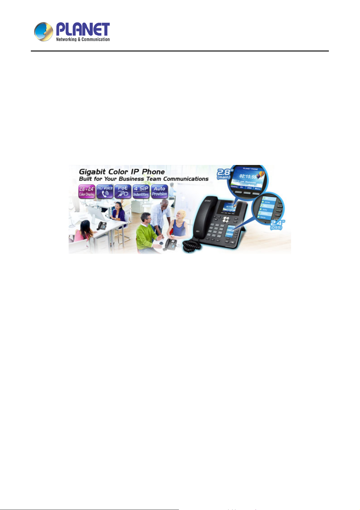
IP Phone with Color Display
As the VIP-2140PT is a high-performance IP phone , it allows you to make calls from any location easil y as
long as it is online. Its 2.8-inch (m ain) and 2.4-inch (D SS) key-mapping LCD monitors with m ulti-languages
make interaction easy b y way of the web-based UI . It provides 12 co nfigurable and 6 multicolored L ED keys,
and offers a clear depiction of caller’s information. It complies with IEEE 8 02.3af/at PoE interfac e and dual
10/100/1000Mbps Ethernet for flexible deployment and supports superior audio quality delivered by the
advanced speaker and microphone system, and the digital signal processor (DSP).
11
Page 12
High Definition Color PoE IP Phone with Dual Display
VIP-2140PT
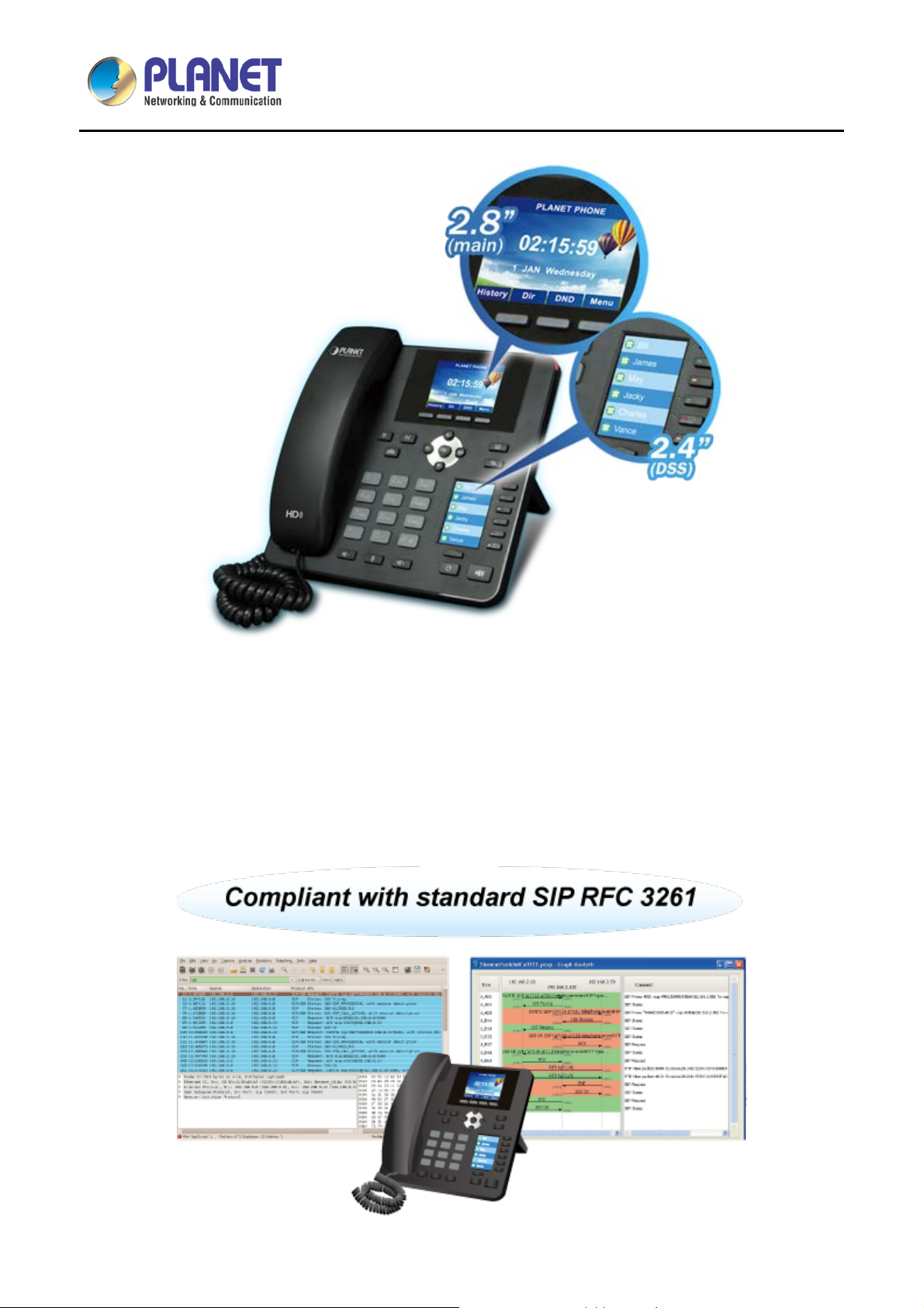
Compliant w ith SIP 2.0
SIP phones continue to gain popularity among businesses as the preferred protocol for enhancing
communication acros s IP networks. T he VIP-2140PT supports Ses si on In iti ati on P r otocol 2. 0 ( RF C 32 61) f or
easy integration with general voice over IP system. The VIP-2140PT is able to broadly interoperate with
equipment provided by VoIP infrastructure providers, thus enabling them to provide their customers with
better voice over IP services.
12
Page 13
High Definition Color PoE IP Phone with Dual Display
VIP-2140PT
Affordable for All Businesses
The VIP-2140PT is definitely affordable for all business establishments who want flexible deployment options
and expansion. It can ef fortlessly deliver secure toll voice q uality by utilizing the cutting-edge 802.1p QoS
(Quality of Service) and IP ToS technologies.
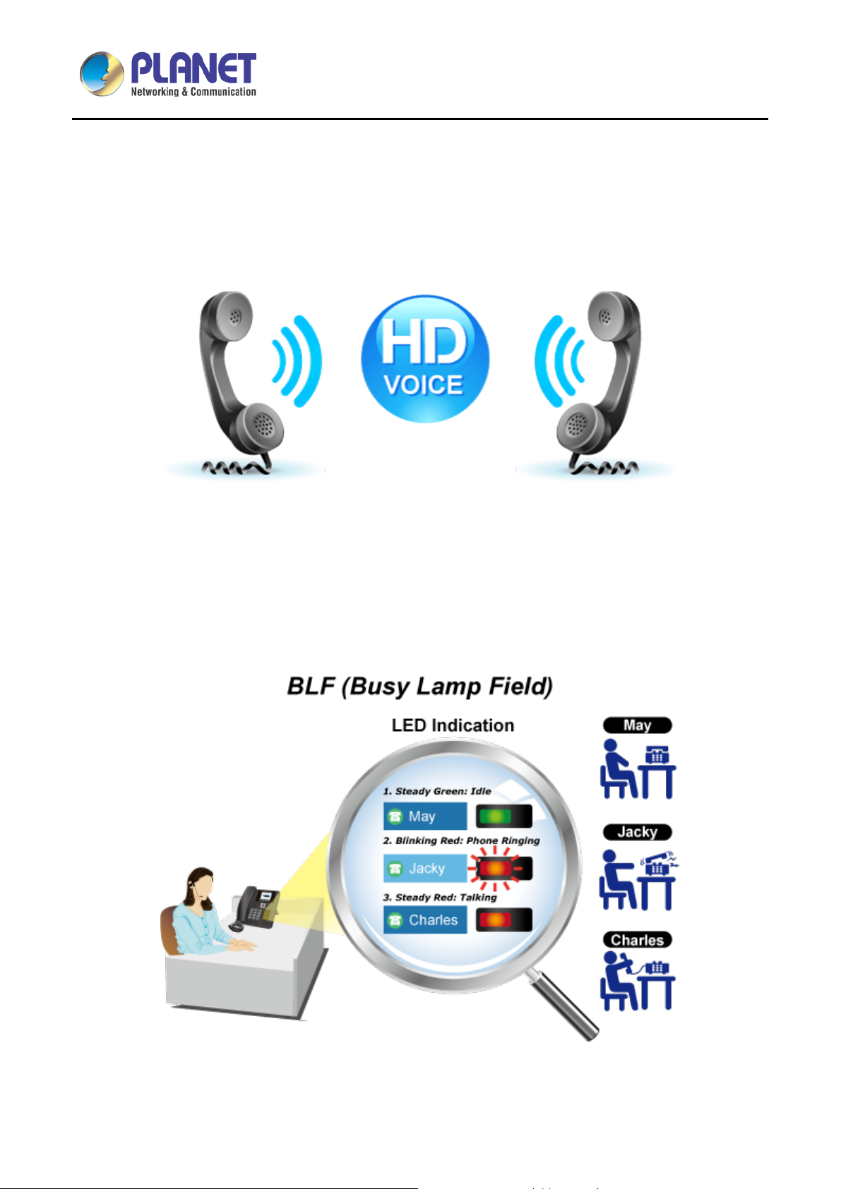
Professional Application
The VIP-2140PT supports Busy Lam p Fie ld (B LF ) function that, via t he l ights on t he phone, enables us ers t o
easily identify the status of other phones which are connected to the same IP PBX, such as busy, idle, ringing,
etc. The connected IP PBX must also support the BLF feature. The BLF f unction is helpful for a receptionist
on the front desk to route all incoming calls smoothly.
13
Page 14

High Definition Color PoE IP Phone with Dual Display
1.3 Features
Highlights
• 2.8-inch (main) and 2.4-inch (DSS) key-mapping LCD monitor
• 30 configurable, 6 multicolored LED keys
• IETE SIP compliant with 4 identities/accounts
• Wideband G.722 HD audio with Handset and Hands-free function
VIP-2140PT
• Multi-language support via the web-based UI
• Gigabit switch and IEEE 802.3af/at PoE compliant
• VPN, VLAN QoS, TR069 and auto-provisioning
Advantageous Applications
• Supports SIP 2.0 (RFC3261)
• Inband, SIP info, RFC 2833 DTMF relay
• Soft keys and function keys programmable
• Echo cancellation: Supports G.168, and a maximum filter length of 96ms in hands-free mode
• Supports voice gain setting, voice activity detection (VAD) and comfort noise generation (CNG)
• Full duplex hands-free speakerphone
• Hands-free headset ringing choice
• Voice codec setting for each SIP line
SIP Applications
• Call forward and transfer (blind/attended)
(available in 15 languages)
• Call holding and waiting
• 3-way conferencing
• Paging and intercom
• Call park, call pickup and call join
• Redial and click to dial
• Secondary dialing automatically
• Incoming calls, outgoing calls and missed calls (Each supports 300 records)
• SMS and speed dial
• Phonebook with up to 500 records
Call Control Features
• Flexible dial map, hotline and empty calling no. for rejected service
• Black list for rejected authenticated calls
14
Page 15

High Definition Color PoE IP Phone with Dual Display
• White list and call limit
• Do not disturb (DND)
• Caller ID display
• Dial without registration
Network Features
• PPPoE/DHCP client
• 802.1 VLAN (voice VLAN/data VLAN)
• VPN (L2TP) and openVPN
• Quality of Service
Maintenance and Management
• Integrated web server prov ides web-based administration and configuration
• Telephone keypad configuration via display menu/navigation
VIP-2140PT
• Automated provisioning and upgrade via HTTPS, HTTP, TFTP
• User authentication for configuration pages
• SNTP time synchronization
• TR069
15
Page 16
High Definition Color PoE IP Phone with Dual Display
1.4 Specifications
VIP-2140PT
Table 1 – Specifications
Product
Hardware
Lines (Direct Numbers)
Display
Feature Keys
VIP-2140PT
4 SIP Lines
Main 2.8-inch (320 x 240) color LCD monitor
DSS Key-mapping color LCD monitor
Keypad: 38 keys, including
4 Soft-keys
6 Function keys
5 Navigation keys
12 Standard Phone Digits keys
3 Volume Control keys, Up/Down/Mute(Microphone)
1 Hands-free key
6 DSS Keys with tri-color LED
1 Page-Jump/Configuration (PJC) key
RJ45 Ethernet jacket x 2:
Network Interfaces
Connectors
Power Requirements
Weight
Dimensions (W x D x H)
Protocols and Standard
Protocols
Network x 1 (802.3af PoE Class 2 enabled)
PC x 1 (Bridged Network)
HD hands-free speaker (0 ~ 7KHz) x 1
HD hands-free microphone (0 ~ 7KHz) x 1
HD handset (RJ9) x 1
IEEE 802.3af
5V 1000mA (optional external power supply)
Power Consumption: Idle – ~ 1.7W, Peak – ~5.7W
770g
196 x 200 x 65 mm
SIP2.0 over UDP/TCP/TLS
RTP/RTCP/SRTP
STUN
DHCP
16
Page 17
High Definition Color PoE IP Phone with Dual Display
2833, 2976, 3261, 3262, 3263, 3264, 3265, 3268, 3311, 3489, 3711,
Request for Comments (RFCs)
Networking
VIP-2140PT
PPPoE
802.1x
L2TP (basic unencryption)
OpenVPN
SNTP
FTP/TFTP
HTTP/HTTPS
TR069
354, 1321, 1350, 1769, 1889, 1890, 2131, 2132, 2616, 2617, 2661,
4346, 4566, 5630, 5865
Physical: 10/100/1000Mbps Ethernet, dual bridged port for PC
Networking
Deployment and Maintenance
Features
bypass
IP Configuration: Static, DHCP, PPPoE
Network Access Control: 802.1x
VPN: L2TP (basic unencryption), OpenVPN
VLAN
QoS
Auto-provisioning via FTP/TFTP/HTTP/HTTPS/DHCP/OPT66/SIP
PNP/TR069
Web management portal
Web-based packet dump
Configuration Export, Import
Phonebook Import, Export
Firmware Upgrade
Syslog
Call Out, Answer, Reject
Mute, Unmute (microphone)
Call Hold, Resume
Call Features
Call Waiting
Intercom
Caller ID Display
Speed Dial
17
Page 18

High Definition Color PoE IP Phone with Dual Display
VIP-2140PT
Anonymous Call (Hide Caller ID)
Call Forwarding (Always/Busy/No Answer)
Call Transfer (Attended/Unattended)
Call Parking, Pick-up (depending on server)
Redial/Auto-Redial
Do-Not-Disturb (per line, per phone)
Auto-Answering (per line)
Voice Message (on server)
Local 3-way Conference
Hot Line
Hot-Desking
Intelligent phonebook (up to 500 entries in total)
Remote phonebook (XML/LDAP)
Call log (100 entries in total, in/out/missed)
Phone Features
Audio Features
Black/White List Call Filtering
Voice Message Waiting Indication (VMWI)
Programmable DSS/Soft keys
Network Time Synchronization
Action URL/Active URI
Multi-language support via the web-based UI: English, Chinese
(Traditional/Simplified), Japanese, Russian, Italian, Turkish,
German, Dutch, Spanish, Hebrew, Polish, French, etc.
HD voice microphone/speaker (handset/hands-free, 0~7KHz
frequency response)
Wideband ADC/DAC 16KHz sampling
Narrowband codec: G.711a/u, G.723.1, G.726-32K, G.729AB
Wideband codec: G.722
Full-duplex acoustic echo canceller (AEC) – a tail length of 96ms in
hands-free mode
Voice activity detection (VAD), comfort noise generation (CNG),
Environment
Operating Temperature
background noise estimation (BNE), noise reduction (NR)
Packet loss concealment (PLC)
Dynamic adaptive jitter buffer up to 300ms
DTMF: In-band, out-of-band – DTMF-relay (RFC2833), SIP info
0 ~ 40 degrees C
18
Page 19

High Definition Color PoE IP Phone with Dual Display
VIP-2140PT
Operating Humidity
Emission
10 ~ 65% (non-condensing)
CE, FCC, RoHS
19
Page 20
High Definition Color PoE IP Phone with Dual Display
VIP-2140PT
Chapter 2. Hardware Interface and Installation
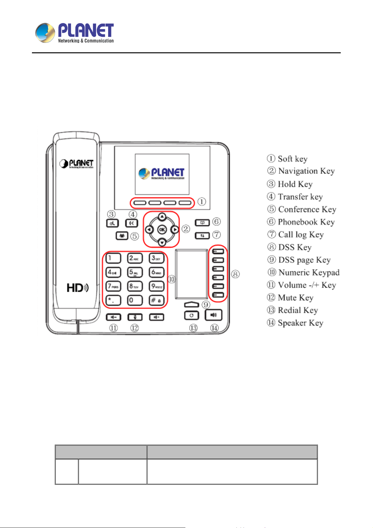
2.1 Physical Descriptions
Figure 1 - Keypad
The above picture shows the keypad layout of the device. Each key provides its own specific function. User
should refer to the illustration in this section about the usage of each key and the description in this document
about each function.
Some keys come with long key press. User can press and hold the key for 1.5 seconds to trigger a function.
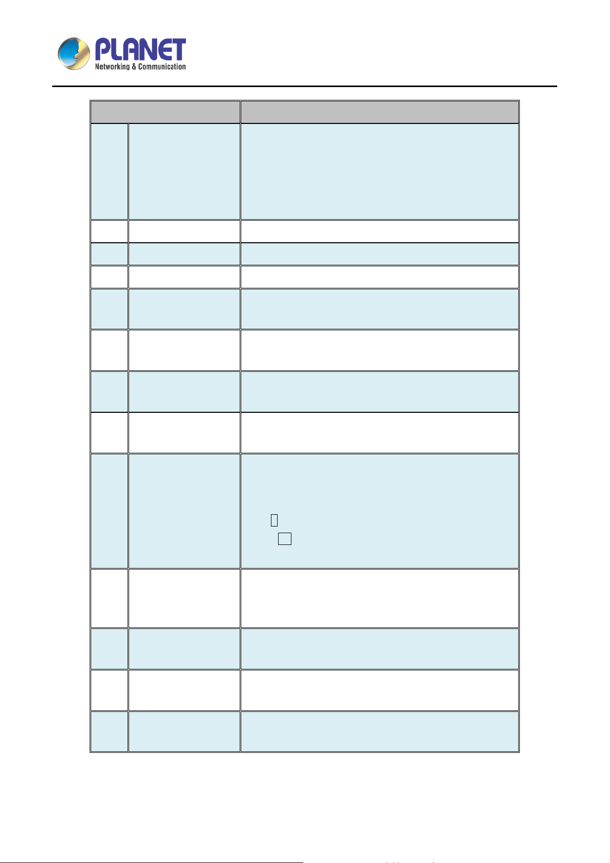
Table 2 - Keypad Descript io ns
Interface Description
Soft-menu Buttons
1
These four buttons provide different functions
corresponding to the soft-menu displayed on the screen.
20
Page 21
High Definition Color PoE IP Phone with Dual Display
age
VIP-2140PT
Interface Description
User can press the up/down navigation key to change line
focus on the talking screen or move the cursor to a listed
Navigation Key
2
item on the screen. In some configuration or text editor
screen, user can press the left/right navigation key to
switch option or move cursor to the left/right.
Hold Key To hold or to resume a call during a conversation
3
Transfer Key To transfer a call to a third party
4
Conference Key To place a conference call
5
By pressing the ‘Phonebook’ button, users can open
Phonebook Key
6
phonebook as a shortcut.
By pressing the ‘Call logs’ button, user can open call logs
Call Log Key
7
as a shortcut.
User can configure them on the web page (for example,
DSS Key
8
Line Key, BLF, DND and MWI state).
By pressing this bu tton o nc e, us er c an switch to DSS LCD
DSS Page Key
9
page one by one.
The 12 standard telephone keys provide the same function
as standard telephones, but some keys also provide
special functions by long pressing the keys.
10
Numeric Keypad
-Key # - Long press to lock the phone. (Default PIN is 123)
-Key Pn – Long press to open DSS LCD p
configuration.
User can press the -/+ button to lower/increase the
11
Volume -/+ Key
ringtone volume in standby mode; user can press the -/+
button to lower/increase the audio volume in talking mode.
User can mute the microphone wit h this button in talking
12
Microphone Mute
mode
By pressing the ‘Redial’ button, user can redial the last
13
Redial
dialed number
By pressing this button once, user can turn on the audio
14
Hands-free Speaker
channel of hands-free speaker
21
Page 22
High Definition Color PoE IP Phone with Dual Display
VIP-2140PT
2.2 Using Handset/ Hands-free Speaker/Headphone
Using Handset
To talk over handset, user shoul d lif t the han dset off the device a nd dia l the number , or dia l the n um ber f irst,
then lift the handset and the num ber will be dialed. User can s witch audio channel to handset by lift ing the
handset when audio channel is opened in speaker or headphone.
Using Hands-free Speaker
To talk over hands-free speaker, user should press the hands-free button and then dial the number, or dial the
number first and then press the hands-free button. User can switch audio channel to the speaker from
handset by pressing the hands-free button when audio channel is opened in handset.
Using Headphone
To use headphone, by default, user sho uld press the h eads et but ton, which is defi ned b y DS S key to turn on
the headphone. Like the handset and hands-free speaker, user can dial the number before or after the
headphone is turned on.
Using Line Keys (Defined by DSS Key)
User can use line k ey to m ake or answer a c all o n spec ific lin e. If han dset h as b een lif ted, the audio ch annel
will be opened in handset, otherwise, the audio channel will be opened in hands-free speaker or headphone.
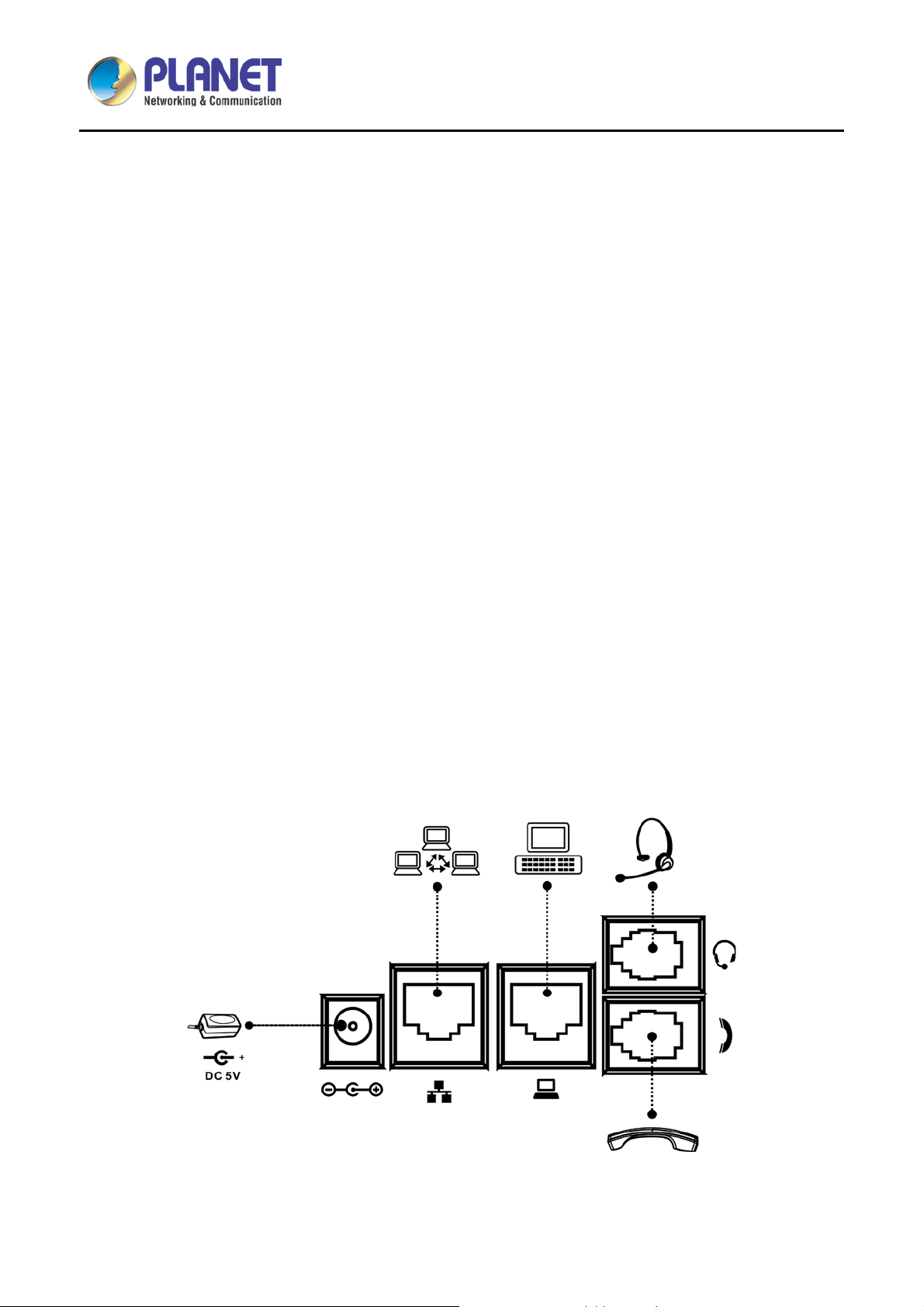
Please connect power adapter, network, PC, handset, and headphone to the corresponding ports as
described in the diagram below.
Figure 2 - Connecting to the Device
22
Page 23
High Definition Color PoE IP Phone with Dual Display
VIP-2140PT
Table 3 - Interface Descriptions
Interface Description
1
Headset
2
Headphone
3 PC (LAN)
4 Internet (WAN)
5 DC 5V
Power adapter is optional for VIP-2140PT model. (This unit does not include the 5V/1000mA
power adapter.)
Connected to the headset interface
Connected to the headphone interface
Use a Cat5 cable to directly connect between the RJ45
connector and a PC to maintain the existing network
structure.
Use one end of a straight Cat5 cable to directly connect to a
switch/hub and the other end to the RJ45 connector for
internet access.
The WAN interface also can be connected with 802.3af PoE
switch or converter for power supply
Power port (This unit does not inc lude t he 5V/ 600mA power
adapter)
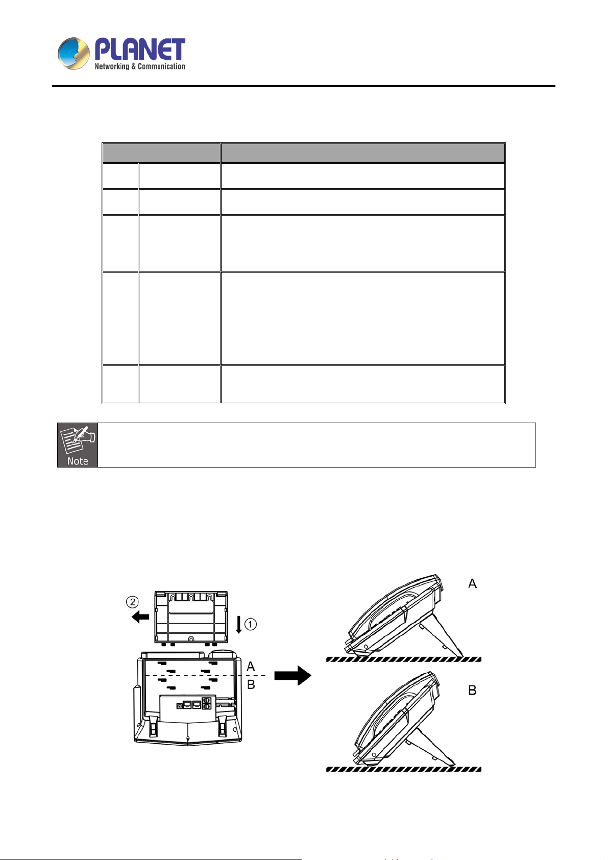
2.3 Desktop and Wall-mount Installation
The device supports t wo installation modes, desktop and wall-mount. To set up the phone on the desktop,
please follow the instructions as shown in the diagrams below.
Figure 3 - Desktop Installation
23
Page 24
High Definition Color PoE IP Phone with Dual Display
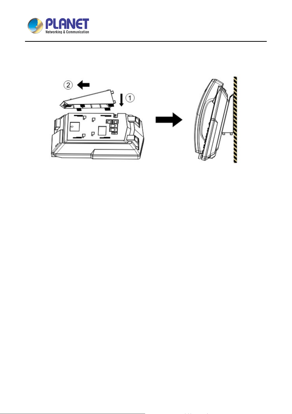
To mount the device on the wall, please follow the instructions shown in the pictures below..
Figure 4 - Wall-mount Installation
VIP-2140PT
24
Page 25
High Definition Color PoE IP Phone with Dual Display
Chapter 3. Introduction to the Phone User
Interface
3.1 Screen User Interface
VIP-2140PT
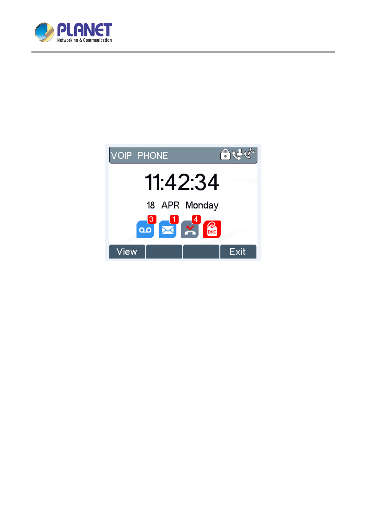
Figure 5 - Screen Layout / Default Standby Screen
The screen user interface is mostly presented in the above layout except some prompt messages. The upper
area is the main screen to display the device’s status and information or data for viewing or editing. The lower
area is the software menu (soft-menu) buttons which will change against user’s action or device’s status.
The above picture shows the default standby screen which is also the root of the soft-menu. The default
standby screen shows the greeting words and effec tive feature indications like voice message, m issed call,
auto-answering, do-not-disturb, call forward, lock state, and the network connectivity. User can get back to the
default standby screen mostly by lifting and putting by the handset.
The icon illustration is described in Appendix I - Icon Illustration.
In some screens, ther e are m ore items or long t ext to be d isplayed which could not f it into the sc reen. The y
will be arranged in a list or multiple lines with a scroll bar. If user sees a scroll bar, us er can use up/down
navigation buttons to scr oll the list. By pressing th e navigation keys a little longer , user can scroll the list or
items at a faster speed.
25
Page 26
High Definition Color PoE IP Phone with Dual Display
VIP-2140PT
Figure 6 - Vertical Scroll Bar
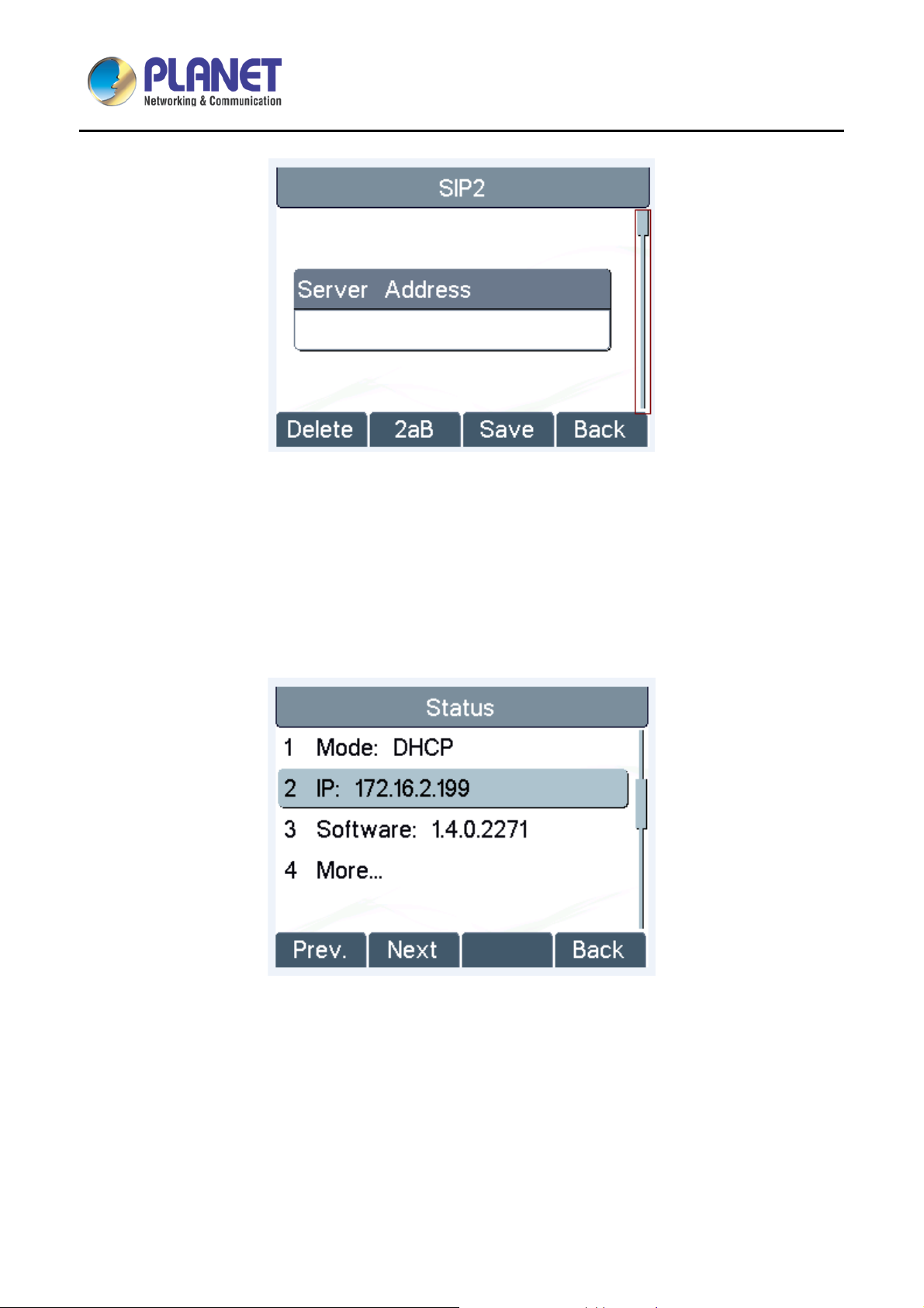
3.2 Web Portal
User can also use the device’s web por tal to manage or operate the de vice. User s hould open the dev ice’s
web portal page by enterin g the device’s IP addres s in a browser. To get the de vice IP address, user could
press the soft-menu button [Menus] -> [Status] or by pressing the [Down] navigation key.
Figure 7 - Check the Device’s IP Address
26
Page 27
High Definition Color PoE IP Phone with Dual Display
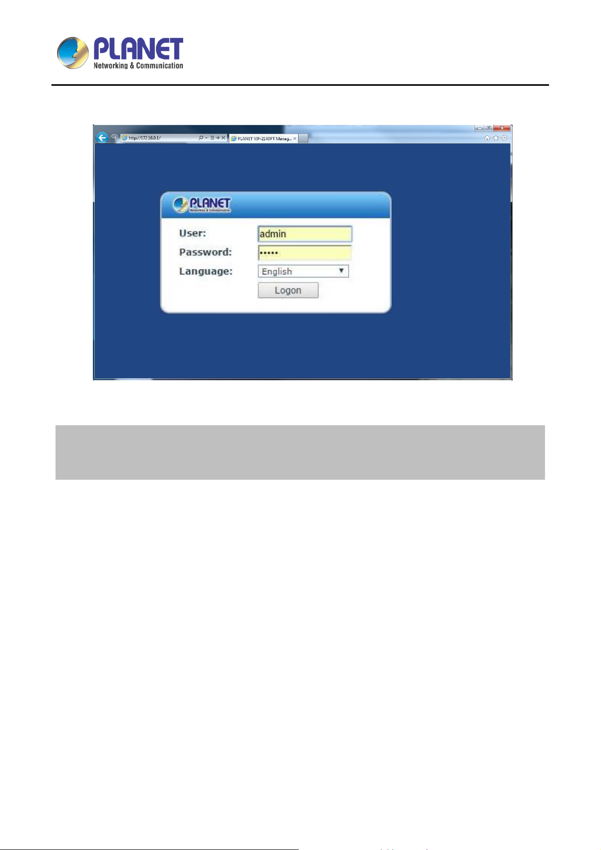
The first screen of the device’s web portal is the login page.
VIP-2140PT
Figure 8 - Web Portal Login Page
Default IP Address: 172.16.0.1
Default username: admin
Default password: 123
User must enter the username and password to log in to the web portal. The default username and
password is “admin” and “123”. For details on web portal operations, please refer to Chapter 7 Web
Portal.
27
Page 28
High Definition Color PoE IP Phone with Dual Display
VIP-2140PT
Chapter 4. IP Phone Setup
In order to get the device r eady for making and receiving phone ca lls, the device must be configured with
correct network configurations and at least one of the lines must be configured with an IP telephony service.
4.1 Network Configuration
The device relies on IP network connection to pro vide service. Unlike tradit ional phone system based o n a
circuit switched wire technology, IP devices are connected to each other over the network and exchange data
in packet basis based on the devices’ IP address.
To enable the device, the network parameters must be configured properly first. To configure network
parameters, user s hould open the network conf iguration screen through soft-m enu [Menu] -> [Settings] ->
[Advanced Settings] -> [Network] -> [Network Settings] from standby screen.
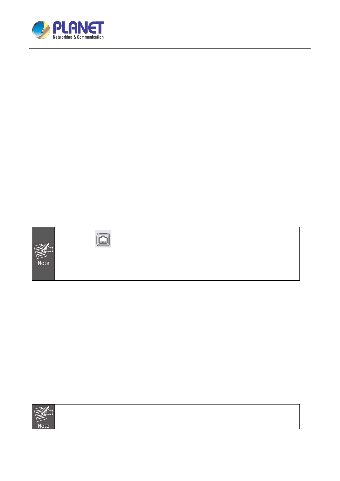
If users see a ‘Network Disconnected’ icon flashing in the middle of screen, it means
the network cable is not correctly connected to the device’s network port. Please check
whether the cable is connected correctly to the device and to the network switch, router, or
modem.
There are three common IP configuration modes.
D ynamic Host Configuration Protocol (DHCP) -- This is the automatic configuration m ode by gett ing
network configurations from a DHCP server. Users need not to configure an y parameters manuall y. All
configuration parameters will be getting from DHCP server and applied to the device. This is
recommended for most users.
Static IP Configuration -- This option allows user to configure each IP parameter manually, including IP
address, subnet mask, default gat ewa y, and DNS s ervers. T his is us ual ly used in an off ice envir onm ent
or by power users.
PPPoE -- This option is often used by users who connect the device to a broadband modem or router. To
establish a PPPoE con nection, user shou ld configure user name and password p rovided by the ser vice
provider.
The device is default configured in Static mode; the default IP address is 172.16.0.1
28
Page 29

High Definition Color PoE IP Phone with Dual Display
VIP-2140PT
4.2 Line Configurations
A line must be configured properly to be able to provide telepho ny service. The line configuration is like a
virtualized SIM card. J ust lik e a SIM card on a mobil e phone, it stor es the service pro vider and the ac count
information used for r egistration and a uthenticati on. When the de vice is appl ied with the conf iguration, it will
register the device to the service provider with the server’s address and user’s authentication as stored in the
configurations.
To configure a line manually, user may open the line configuration screen through soft-menu button [Menu] ->
[Settings] -> [Advanced Settings] -> [Accounts] -> [SIP1] / [SIP2] -> [Basic Settings] from the standby screen.
User must enter the correct PIN code to be able to go to advanced settings to edit line
configuration. (The default PIN is 123.)
The parameters and screens are listed in the diagrams below.
Figure 9 - Configure SIP Proxy Server Address
29
Page 30

High Definition Color PoE IP Phone with Dual Display
VIP-2140PT
Figure 10 - Configure SIP Proxy Serv er Po rt
Figure 11 - Configure SIP Username
Figure 12 - Configure Authentication Name
30
Page 31

High Definition Color PoE IP Phone with Dual Display
VIP-2140PT
Figure 13 - Configure SIP Authentication Password
Figure 14 - Configure Display Name
Figure 15 - Enable/Disable Outbound Proxy
31
Page 32

High Definition Color PoE IP Phone with Dual Display
VIP-2140PT
Figure 16 - Enable/Disable SIP Line
Save the adjustment by pressing [OK] or [Save] when done.
For users who want to configure more options, user should use web management portal to modify or
Advanced Settings in accounts on the individual line to configure those options.
Figure 17 - Configure Advanced Line Options
Figure 18 - Configure SIP Realm/Domain
Figure 19 - Configure Unregistered Dial
32
Page 33

High Definition Color PoE IP Phone with Dual Display
VIP-2140PT
Figure 20 - Enable/Disable Anony mous
Figure 22 - Enable/Disable STUN
Figure 21 - Configure DTM F Mode
Figure 23 - Configure Local Port
Figure 24 - Configure Ring Type
33
Figure 25 - Configure MWI Number
Page 34

High Definition Color PoE IP Phone with Dual Display
VIP-2140PT
Figure 26 - Configure Pickup Numb er
Figure 28 - Configure Join Call Number
Figure 27 - Configure Park Number
Figure 29 - Enable/Disable Missed Call
Figure 30 - Enable/Disable Feature Sync
34
Figure 31 - Enable/Disable SCA
Page 35

High Definition Color PoE IP Phone with Dual Display
VIP-2140PT
On the device, user can o nly configure whether ST UN/Outbound Prox y is enabled to change
the STUN/Outboun d Prox y server ad dress. User mus t edit in the de vice web portal. (Refer to
7.15 LINES (Global6HWWLQJV DQG 7.12 LINES (SIP)
35
Page 36

High Definition Color PoE IP Phone with Dual Display
VIP-2140PT
Chapter 5. Using the Phone
5.1 Making Phone Calls
Default Line
The device provides 2 line services. If both l ines are configured, user ca n make or receive phon e calls on
either line. If default line is conf igured b y user, th ere will be a d ef ault line t o be us ed for making outgoing call
which is indicated on the top left cor ner. To change t he default line, user can press the left/right na vigation
button to switch between t wo lines . To enab le or d isable d efault line, user can pr ess [m enu] - > [Features] ->
[Default Line] or configure from Web Interface (Web/PHONE Settings/Features).
Figure 32 - Default Line
Dialing Methods
User can dial a number by,
Entering the number directly
Selecting a phone number from phonebook contacts (Refer to 5.5 Using Phonebook)
Selecting a phone number from cloud phonebook contacts (Refer to 5.9 Using Cloud Phonebook)
Selecting a phone number from call logs (Refer to 5.11 Call Logs)
Redialing the last dialed number
Dialing Number then Opening Audio
To make a phone call, user can firstly dial a number by one of the above methods. When the dialed number is
completed, user can pr ess the [Dial] button on t he soft-menu, or pr ess the hands-free butto n to turn on the
speaker or headphone, or lift the handset to call out with the current line, or user can press the line key to call
out with a specified line.
36
Page 37

High Definition Color PoE IP Phone with Dual Display
Figure 33 - Dialing a Number befo re Audio Channel Opened
Opening Audio and then Dialing the Number
VIP-2140PT
Another alternative is the traditional way to firstly open the audio channel by lifting the handset, turning on the
hands-free speak er or headphone by pressing hands-f ree button, or lin e key, and th en dial the number with
one of the above met hods. When the number is dialed completely, user can pre ss the [Dial] button or [O K]
button to call out, or the number will be dialed out automatically after timeout.
Figure 34 - Dial a Number after Audio Channel Opened
For some users who get used to dial a number imm ediatel y by press ing # key, the user must
login to the web to enable ‘Press "#" to invoke dialing’ option in page [Line] -> [Dial Plan] ->
“Basic Settings” and apply it.
Cancel Call
While calling the num ber, user can press the [End] button or close the audio channel by putting bac k the
handset or press the hands-free button to end the call.
37
Page 38

High Definition Color PoE IP Phone with Dual Display
Answering Incoming Call
VIP-2140PT
Figure 35 - Calling Remote Party
When there is an incoming cal l while the d evice is idle, user will be alerted to the following incom ing call on
the screen.
Figure 36 - Incoming Call Screen
User can answer the call by lifting the handset, open headphone or speaker phone by pressing the hands-free
button, or the [OK] / [Ans wer] button. To divert the in coming call, user should pres s the [Divert] b utton. To
reject the incoming call, user should press the [Reject] button.
Talking
When the call is connected, user will see a talking mode screen as shown in the following figure.
38
Page 39

High Definition Color PoE IP Phone with Dual Display
Figure 37 - Talking Mode Screen
1. Audio Channel -- The icon reflects the current audio channel being used.
VIP-2140PT
2. Current Line -- The line is being used on the call.
3. Remote Party -- The name or number of the remote party.
4. Talking time -- The time has passed since the call was established.
5. Screen Pages -- The number of screen pages. User can press the up/down navigation buttons to switch
screen page.
Call Holding/Resuming
User can hold the remote party by pressing the [Hold] button and the button will be changed to [Resume] icon.
User can press the [Resume] button to resume the call.
Figure 38 - Call Holding Screen
39
Page 40

High Definition Color PoE IP Phone with Dual Display
VIP-2140PT
Call Ended
When user finishes the call, user can put the handset back to the device to hang u p the call or press the
hands-free button to close the audio channel to hang up.
When the call is hel d or in holding s tate, the user m ust press the [Resum e] butto n to return to
call mode, or putti ng the handset back to the device or pressing the speaker-free button to
hang up is not available.
5.2 Make/Receive Second Call
The device can s upport up to two concurr ent calls. When ther e is already a call es tablished, user can sti ll
answer another incoming call on either lines or make a second call on either lines.
Second Incoming Call
When there is another incom ing call durin g talk ing a phone call, this c all will be waiting f or user t o answer it.
User will see the ca ll m essage in th e middle of the current scr een. The device will not be ringi ng but playing
call waiting tone in the audio channel of the current call and the LED will be flashing in green. User can accept
or reject the call which is t he same as norm al incoming call. W hen the wait ing call is ans wered, the firs t call
will be put on hold automatically.
Figure 39 - Second Incoming Call Screen
Second Outgoing Call
To make a second c all, user m ay press the [XFER] / [Conf] butto n to mak e a new call on the default line or
press the line key to make new call on a specific line. Then dial the number the same way as making a phone
call. Another alternative for making second call is to press the DSS Keys dialing out from the configured Keys
(BLF/Speed Dial). W hen user is making a sec ond call with the above m ethods, the firs t call could be plac ed
on hold manually first or will be put on hold automatically at the second dial.
40
Page 41

High Definition Color PoE IP Phone with Dual Display
VIP-2140PT
Switching between Two Calls
When there are two calls established, user will see a dual call screen as shown in the following picture.
Figure 40 - Dual Calls
User can press the up/down navigation butt on to switc h screen page, and switch call focus by press ing the
[Hold] / [Resume] button.
Ending One Call
User may hang up the current call by c losing the audio channe l or press the [End] butto n. The device will
return to single call mode in holding state.
5.3 Join/Split Two Calls (3-way Local Conference)
In the dual call m ode, us er can j oin two calls i nto a c onferenc e call b y press ing the [Conf] butt on. When tw o
calls are joined, user can split them by pressing the [Split] button.
Figure 41 - Conference Call
41
Page 42

High Definition Color PoE IP Phone with Dual Display
VIP-2140PT
5.4 Call Transfer
When the user is t alking with a remote p arty and wish to transf er the call to another rem ote part y, there are
two ways to transfer the call, attended and unattended.
Attended Transfer
The attended call transf er is also known as the ‘po lite m ode’ which is to dial through the o ther remote par ty,
wait for the remote party to answer the call and then transfer the call.
This is the same procedure as making two concurrent calls. In the dual call mode, press the [XFER] button to
transfer the first party to the second one.
Unattended/Blind Transfer
Unattended transf er is also known as ‘Fire an d Forget’ mode. Ins tead of connecti ng to the sec ond part y first
and confirming the sec ond call is established, user p ress the [XFER] button first and then dial the second
party number. When the num ber is dialed, us er can press the [XFER] button again and the first part y will be
transferred to the second.
This is like helping t he first party to dial to the second one. However, th e transfer could be successful if the
second party answered it, or could be failed if the second party is busy or rejected it.
More advanced transfer configuration, please refer to 7.14 LINES (Dial Plan).
5.5 Using Phonebook
User can save contacts’ information in the phonebook and dial the contact’s phone number(s) from the
phonebook. To open t he p honebook , user can pr ess the soft-menu butt on [D ir] in the def ault st andb y screen
or keypad.
By default the phonebook is empty, user may add contact(s) to the phonebook manually or from call logs.
42
Page 43

High Definition Color PoE IP Phone with Dual Display
VIP-2140PT
Figure 42 - Phonebook screen
The device can save up to a total of 500 contacts.
Figure 43 - Phonebook is Empty
When there are contact records in the phonebook, the contact records will be arranged in the alphabet order.
User may browse the contacts with the up/down navigation keys. User may fast scroll the contact list by
holding the up/down naviga tion keys. The rec ord indic ator tel ls user which co ntac t is curr ently foc use d. Us er
may check the contact’s information by pressing the [OK] button.
43
Page 44

High Definition Color PoE IP Phone with Dual Display
VIP-2140PT
Figure 44 - Browsing Phonebook
44
Page 45

High Definition Color PoE IP Phone with Dual Display
VIP-2140PT
5.6 Add/Edit/Delete Contact
To add a new contact, user should press the [Add] button to open Add Contact screen and enter the following
contact information:
Contact Nam e
Tel. Number
Mobile Number
Other Number
Ring Tone
Contact Group
Figure 45 - Add New Contact
User can edit a contact by pressing the [Option] -> [Edit] button.
To delete a contac t, us er s hould m ove th e rec ord i ndi cator to the posit ion of the c ontact t o be delet ed, press
the [Option] -> [Delete] button and confirm with [Yes].
5.7 Add/Edit/Delete Group
User can open the group list by pressing the [Groups] button in phonebook screen.
By default, the group list is blank. User can create his/her own groups, edit the group name, add or remove
contacts in the group, and delete a group.
To add a group, press the [Add] button.
To delete a group, press the [Option] -> [Delete] button.
45
Page 46

High Definition Color PoE IP Phone with Dual Display
To edit a group, press the [Edit] button.
VIP-2140PT
Figure 46 - Group List
5.8 Browse and Add/Remove Contacts in Group
User can browse contacts in a group by opening the group in group list with the [OK] button.
Figure 47 - Browsing Contacts in a Group
When user is browsing con tacts of a group, user can also add or rem ove contacts in that group by press ing
the [Add] button to enter the group contacts manage ment screen. Press the [Add] bu tton to create a new
contact for the group; press the [Option] button to remove the contact from the group.
46
Page 47

High Definition Color PoE IP Phone with Dual Display
Figure 48 - Add/Remove Contacts in a Group
5.9 Using Cloud Phonebook
VIP-2140PT
Cloud phonebook allows u ser to c onfigure the de vice to d ownload a phone book f rom a cloud serv er. This is
very useful for office users to use the phonebook from a single source and save the effort to create and
maintain the contact list indiv idually. It is also a useful tool for us er to synchr onize his /her phone book f rom a
personal mobile phone to the device with Clo ud Pho n ebook Service which is to be provided publicly soon.
The cloud phonebook is ONLY temporarily downloaded to the device each time it is opened on
the device to ensure the user gets the up-to-date phonebook. However, the downloading may
take a couple of seconds depending on the network condition. Therefore, it is highly
recommended to the users to save important contacts from cloud to local phonebook to save
the time of waiting for downloading.
To open cloud phonebook list, press [Cloud Phonebook] in phonebook screen.
Figure 49 - Cloud Phonebook List
47
Page 48

High Definition Color PoE IP Phone with Dual Display
VIP-2140PT
5.10 Open Cloud Phonebook
In cloud phonebook screen, user can open a cloud phonebook by pressing the [OK] / [Enter] button. The
device will start downloading the phonebook. If downloading failed, user will be prompted with a warning
message.
Once the cloud phonebook is downloaded completely, user may browse the contact list and dial the same
contact number as in local phonebook.
Figure 50 - Downloading Cloud Phonebook
Figure 51 - Browsing Contacts in Cloud Phonebook
48
Page 49

High Definition Color PoE IP Phone with Dual Display
VIP-2140PT
5.11 Call Logs
The device can store up to 600 call log records and user can open the call logs to check all incoming,
outgoing, and missed call records by pressing the soft-menu button [History].
In the call logs screen, user may browse the call logs with the up/down navigation keys.
Each call log record is presented with ‘call type’ and ‘call party number/name’. User can check further call log
detail by pressing the [OK] button and dial the number with the [Dial] b utton, or add the call log number to
phonebook by pressing [Option] -> [Add to Contact] .
User can delete a call log b y pressing the [Delete] bu tton and can clear all ca ll logs by pressing the [Clear]
button.
Figure 52 - Call Logs
User can also filter c all logs with specific cal l log type to narrow down the call log records by pressi ng the
left/right navigation button and select one of the call log types in the soft-menu buttons.
- Missed Calls
- Received Calls/Incoming Calls
- Dialed Calls/Outgoing Calls
49
Page 50

High Definition Color PoE IP Phone with Dual Display
5.12 Voice Message
VIP-2140PT
Figure 53 - Filter Call Log Type
If the service of the lines s upports vo ice message f eature, when the us er is not avail able to answer t he call,
the caller can leave a voic e message on t he server to the user. User will receive voice m essage notificat ion
from the server and device will prompt a voice message waiting icon on the standby screen,
Figure 54 - New Voice Message Notification
To retrieve the voice messages, user must configure the voice message number first. Once the voice
message number is c onfigured, us er can r etrie ve the voice m es sage of a line by pr essing th e [Dial ] button in
the voice message screen.
When the device is in the default standby mode,
Check the [MWI] button.
Press the [MWI] button to open voice message configuration screen, select the line to be configured with
50
Page 51

High Definition Color PoE IP Phone with Dual Display
VIP-2140PT
the up/down navigation keys.
Press the [Edit] button to enable and edit the voice message number, when done, press the [OK] / [Save]
button to save the configuration.
Figure 56 - Configure the Voice Message Number
5.13 Do-Not-Disturb
Figure 55 - Voice Message Screen
User may enable Do-Not-Disturb (DND) f eat ure on the device to reject inc oming calls (including c al l w ait ing).
The DND can be enabled on line basis.
To quickly enable or disable the DND on all lines,
When the device is in the default standby mode,
51
Page 52

High Definition Color PoE IP Phone with Dual Display
VIP-2140PT
Press the [DND] button to enable DND on all lines an d icon will be displayed on the screen.
Press the [DND] button again to disable DND on all lines and icon will be dis a ppeared.
Figure 57 - DND Enabled on All Lines
If user wishes to enable or disable DND on a specific line, user could change the DND mode in DND
configurations.
Press the soft-button [Menu] till you find the [Features] item.
Enter [Features] item till you find the [DND] item.
Enter [DND] item till you find [DND item .
Press the left/right navigation key to change the DND mode or DND state on specific line. When done,
press the [Save] button to save the changes.
User will see icon ‘SIP Do Not Disturb’ against the enabled line.
Figure 58 - Configure DND on Line
52
Page 53

High Definition Color PoE IP Phone with Dual Display
VIP-2140PT
5.14 Auto-Answering
User may enable auto-answering feature on the devic e an d a n y inc oming call will be aut omatically answered
(not including call waiting). The auto-answering can be enabled on line basis.
When the device is in the default standby m ode, if user wishes to enable or di sable auto-answering on a
specific line or change the auto-answering delay time, user could change the auto-answering configuration by
adopting the following steps:
Press soft-button [Menu] till you find the [Features] item.
Enter [Features] item till you find the [Auto Answer] item.
Enter [Auto Answer] item to change the auto-answering configuration on a specific line
Press the left/right navigation button to select the auto -answering option. When done, press the [Save]
button to save the changes.
The default auto-answering delay is 5 seconds.
Figure 59 - Configure Auto-answer ing on Line1
Figure 60 - Auto-answering Enabled on Line1
53
Page 54

High Definition Color PoE IP Phone with Dual Display
VIP-2140PT
5.15 Call Forward
Call forward is also known as ‘Call Diver t’ which is to divert the incoming cal l to a specific num ber based on
the conditions and configurations. User can configure the call forward settings of each line.
There are three types:
Unconditional Call Forward -- Forward any incoming call to the configured number.
Call Forward on Busy -- When user is busy, the incoming call will be forwarded to the configured
number.
Call Forward on No Answer -- When user does not answer the incoming call after the configured delay
time, the incoming call will be forwarded to the configured number.
To configure call forward, when the device is in the default standby mode,
Press soft-button [Menu] till you find the [Features] item.
Enter [Features] item till you find the [Call Forward] item.
Press the [Call Forward] button to open call forward configuration screen and select the line to be
configured with up/down navigation keys.
Press the [Enter] button to edit the call forward settings.
Select the call forward type with the up/down navigation keys. Click the [Enter] button to configure the
call forward number and delay, if applicable.
Enable or Disable call forward with the left/right navigation buttons against specific lines and types.
If select ‘Enable’, browse the setting parameters with the up/down navigation keys and enter required
information. When done, press the [Save] / [OK] button to save the changes.
Figure 61 - Select Line for Call F o rward Configuration
54
Page 55

High Definition Color PoE IP Phone with Dual Display
VIP-2140PT
Figure 62 - Select Call Forward Type
Figure 63 - Activate Call Forward and Configure Call Forward Number
Figure 64 - Set Delay Time for Call Forward on No Answer
55
Page 56

High Definition Color PoE IP Phone with Dual Display
VIP-2140PT
Chapter 6. Phone Settings
6.1 Adjust Audio Volume
When the device is in the default standby mode,
Press soft-button [Menu] till you find the [Settings] item.
Enter [Settings] item till you find the [Basic Settings] item.
Enter [Basic Settings] item till you find [Voice Volume] item.
Enter [Voice Volume] item and you will find [Handset Volume], [Handsfree Volume] and [Headset Volume]
item.
Enter [Handset Volume] or [Handsfree Volume] or [Headset Volume] item, press the Left/Right
navigation keys to adjust the audio volume for different mode.
Save the adjustment by pressing [OK] or [Save] when done.
6.2 Set Ring Tone Volume and Type
When the device is in the default standby mode,
Press soft-button [Menu] till you find the [Settings] item.
Enter [Settings] item till you find the [Basic Settings] item.
Enter [Basic Settings] item till you find [Ring Settings] item.
Enter [Ring Settings] item and you will find [Ring Volume] and [Ring Type] item.
Enter [Ring Volume] item and you find [Headset Volume] and [Handsfree Volume] item.
Enter [Headset Volume] or [Handsfree Volume] item, press the left/right navigation key to
adjust the ring volume.
Save the adjustment by pressing [OK] when done.
Enter [Ring Type] item, press the left/right navigation keys to change the ring type.
Save the adjustment by pressing [OK] when done.
6.3 Adjust LCD Contrast
When the device is in the default standby mode,
Press soft-button [Menu] till you find the [Settings] item.
Enter [Settings] item till you find the [Basic Settings] item.
Enter [Basic Settings] item till you find [Screen Settings] item.
Enter [Basic Settings] item till you find [Contrast] item.
Enter [Contrast] item, press the left/right navigation keys to adjust the LCD contrast.
56
Page 57

High Definition Color PoE IP Phone with Dual Display
VIP-2140PT
Save the adjustment by pressing [OK] or [Save] when done.
6.4 Set Device Time/Date
When the device is in the default standby mode,
Press soft-button [Menu] till you find the [Settings] item.
Enter [Settings] item till you find the [Basic Settings] item.
Enter [Basic Settings] item till you find [Time & Date] item.
Enter [Time & Date] item, use the up/dow n nav iga tion keys to edit the time/date parameters and save the
settings by pressing [OK] or [Save] when done.
Table 4 - Time Settings Parameters
Parameters Description
Auto/Manual
Mode
SNTP Server SNTP server address
Time Zone Select the time zone
12-hour Clock Display the clock in 12-hour format
Daylight Saving Time Enable or Disable the Daylight Saving Time
Time format
Auto: Enable network time synchronization via SNTP protocol,
default enabled.
Manual: User can modify data manually.
Select one of the following time formats:
1 JAN, MON
1 January, Monday
JAN 1, MON
January 1, Monday
MON, 1 JAN
Monday, 1 January
MON, JAN 1
Monday, January 1
DD-MM-YY
DD-MM-YYYY
MM-DD-YY
MM-DD-YYYY
YY-MM-DD
YYYY-MM-DD
Date (Only Mode = Manual) Edit the date of the device in the format of yyyy/mm/dd.
Time (Only Mode = Manual) Edit the time of the device in the format of hh:mm:ss.
57
Page 58

High Definition Color PoE IP Phone with Dual Display
Parameters Description
Hh=00~23, mm=00~59, ss=00~59
6.5 Set Device Language
When the device is in the default standby mode,
Press soft-button [Menu] till you find the [Settings] item.
Enter [Settings] item till you find the [Basic Settings] item.
Enter [Basic Settings] item till you find [Language] item.
User can change the language by using the navigation keys.
6.6 Rebo ot the Device
VIP-2140PT
When the device is in the default standby mode,
Press soft-button [Menu] till you find the [Reboot System] item.
Press the [OK] or [Enter] button, a warning message “Reboot Now?” will be prompt to user.
Press the [Yes] or [OK] button to execute the reset command, or [No] to exit.
6.7 Reset to Factory Default
When the device is in the default standby mode,
Press soft-button [Menu] till you find the [Settings] item, and press [OK] or [Enter] button.
Enter [Advanced Set tin gs ] item, then input the device PIN (Default PIN is 123) to enter the interface.
Enter [Reset to Default] item, then a warning message “Factory Reset, Continues?” will be prompt to
user.
Press the [Yes] or [OK] button to execute the reset command, or [No] to exit.
58
Page 59

High Definition Color PoE IP Phone with Dual Display
VIP-2140PT
Chapter 7. Web Portal
7.1 Web Portal Authentication
User can log in to the device web por tal to manage the device or user’s prof ile. User must provide correct
username and password to be able to log in.
7.2 Web Call
Besides making and receiving phone calls by operating the device directly, user could also make and receive
phone calls by operating the controls in the web portal.
The web call is particularly suitable for users wh o use headphone. User can dial o ut a number by click ing the
[Dial] button on top of the title of the web portal page, or click a contact in the phonebook, or click a number in
the call logs, to make phone c all and press the [Answer ] button to answer incoming c all. User can click the
[Hang up] button to e nd the call. All these operation can be d one from the web porta l without touching t he
phone.
The web call is limited to make a single call. To make or answer a second call is not allowed.
Figure 65 - Web Call Controls
59
Page 60

High Definition Color PoE IP Phone with Dual Display
VIP-2140PT
Figure 66 - Web Call, Entering Nu mber and Select Line
7.3 SYSTEM (Information)
User can get the following system information of the device on this page:
Model
Hardware Versi on
Software Versio n
Uptime
Last uptime
MEMInfo
And also summarization of network status:
Network Mode
MAC
IP
Subnet Mask
Default Gateway
Besides, summarization of SIP account status:
SIP User
SIP account status (Registered/Unapplied/Trying/Timeout)
60
Page 61

High Definition Color PoE IP Phone with Dual Display
VIP-2140PT
7.4 SYSTEM (Account)
User may change his/her web authentication password on this page.
For users with Administrato rs privilege, the user c an also manage user ac counts by adding or de leting user
account and assign privilege and password to new account.
There are two types of user privilege, Administrators and Users. If a user account is created as Users
privilege, this account will have limited accessibility to the device and cannot change some device settings.
The user account can be used to operate the device or ac cess the device web portal b y logging in to the
device or its web. User should log in to device web portal with his/her username and web password.
The device is shipped with a default user account. The username and password for the default
account are “admin” and “123” which are shown on the bottom side of the device.
7.5 SYSTEM (Configurations)
Users with Ad ministrat ors privilege c an export or im port the device conf iguration on this page and r eset the
device to factory default.
7.6 SYSTEM (Upgrade)
The device supports online upgrade by periodically checking the software release version on the cloud server.
Meanwhile, user c an download the software an d upgrade the d evice manuall y when there is trouble for t he
device to connect to the cloud server.
7.7 SYSTEM (Auto Provision)
The Auto Provision setti ngs help IT manager or service prov ider to easil y deplo y and manage th e devic es in
mass volume. For details on Auto Provision, please read “VIP-2140PT Administration Guide”.
61
Page 62

High Definition Color PoE IP Phone with Dual Display
VIP-2140PT
7.8 SYSTEM (Tools)
Tools provided on this page help users to identify issues at troubleshooting. Please refer to Chapter 9
Troubleshooting for more details.
Besides, the device also provided the screenshot feature to user, including mail screen and sub-screen.
7.9 NETWORK (Basic)
User can configure the network connection type and parameters on this page.
7.10 NETWORK (Advanced)
The network advanced s ettings is often configured by IT m anager to enhance the quality of service of the
device. The configurations are addressed in “VIP-2140PT Administration Guide”
7.11 NETWORK (VPN)
User may configure a VPN c onnec tion on this page. Please refer to 8.1 VPN for more details.
7.12 LINES (SIP)
The service of th e line is configured on t his pag e; choose the SIP line ( SIP 1 or SIP 2) to configure. Cl ic k the
drop-down arrow to adjust configuration accounting on each line.
Table 5 - Line Configuration on Web
Parameters Description
Basic Settings
Line Status
Display the current line status on the loading page. To get the
up to date line status, user has to refresh the page manually.
Username Enter the username of the service account.
Display Name Enter the display name to be sent in a call request.
Authentication Name Enter the authentication name of the service account
Authentication Password Enter the authentication password of the service account
SIP Proxy Server Address Enter the IP or FQDN address of the SIP proxy server
62
Page 63

High Definition Color PoE IP Phone with Dual Display
Parameters Description
SIP Proxy Server Port Enter the SIP proxy server port; default is 5060
VIP-2140PT
Outbound Proxy Address
Enter the IP or FQDN address of outbound proxy server
provided by the service provider
Outbound Proxy Port Enter the outbound proxy port; default is 5060
Realm Enter the SIP domain if requested by the service provider
Activate Whether the service of the line should be activated
Set the priority and availability of the codecs by adding or
Codec Settings
removing them from the list.
Advanced Settings
Enable unconditional call forward; all incoming calls will be
Unconditional Call Forward
forwarded to the number specified in the next field.
Unconditional Call Forward Number Set the number of unconditional call forward.
Enable call forward on busy, when the phone is busy, any
Call Forward on Busy
incoming call will be forwarded to the number specified in the
next field.
Call Forward Number on Busy Set the number of call forward on busy.
Enable call forward on no answer, when an incoming call is
Call Forward on No Answer
not answered within the configured delay time, the call will be
forwarded to the number specified in the next field.
Call Forward Number on No Answer Set the number of call forward on no answer
Set the delay time of not answered call before being
Call Forward Delay on No Answer
forwarded.
Enable hotline configuration; the device will dial to the specific
Enable Hotline
number immediately at audio channe l ope ned b y off-hook
handset or turn on hands-free speaker or headphone.
Hotline Number Set the hotline dialing number.
Set the delay for hotline before the system automatically
Hotline Delay
dialed it.
Enable auto-answering; the incoming calls will be answered
Enable Auto Answering
automatically after the delay tim e.
Set the delay for incoming call before the system
Auto Answering Delay
automatically answered it.
Enable the device to subscribe a voice message waiting
Subscribe For Voice Message
notification, if enabled, the device will receive notification from
the server if there is voice message waiting on the server.
Voice Message Number Set the number for retrieving voice message.
63
Page 64

High Definition Color PoE IP Phone with Dual Display
Parameters Description
Voice Message Subscription Period Set the interval of voice message notification subscription.
VIP-2140PT
Enable DND
Enable Do-not-disturb; any incoming call to this line will be
rejected automatically.
Blocking Anonymous Call Reject any incoming call without presenting caller ID.
Set the device to use 182 response code at call waiting
Use 182 Response for Call Waiting
response.
Anonymous Call Standard Set the standard to be used for anonymous.
Dial Without Registration Set call out by proxy withou t registration.
Set the user agent; the default is Model with Software
User Agent
Version.
Use Quote in Display Name Whether to add quote in display name.
Ring Type Set the ring tone type for the line.
Set the type of call conference; Local = set up call conference
by the device itself; maximum supports two remote parties,
Conference Type
Server = set up call conference by dialing to a conference
room on the server.
Set the conference room number when conference type is set
Server Conference Number
to be Server.
Transfer Timeout Set the timeout of call transfer process.
Enable Long Contact Allow more parameters in contact field per RFC 3840.
If enabled, the phone will save missed calls into the call
Enable Missed Call Log
history record.
If setting enabled, the device will use single codec in
Response Single Codec
response to an incoming call request.
When this setting is enabled, the features in this section will
not be handled by the device itself but by the server instead.
Use Feature Code
In order to control the enabling of the features, the device will
send feature code to the server by dialing the number
specified in each feature code field.
Enable DND Set the feature code to dial to the server.
Disable DND Set the feature code to dial to the server.
Unconditional Enable Call Forward Set the feature code to dial to the server.
Unconditional Disable Call Forward Set the feature code to dial to the server.
Enable Call Forward on Busy Set the feature code to dial to the server.
Disable Call Forward on Busy Set the feature code to dial to the server.
Enable Call Forward on No Answer Set the feature code to dial to the server.
64
Page 65

High Definition Color PoE IP Phone with Dual Display
Parameters Description
Disable Call Forward on No Answer Set the feature code to dial to the server.
Enable Blocking Anonymous Call Set the feature code to dial to the server.
Disable Blocking Anonymous Call Set the feature code to dial to the server.
VIP-2140PT
Specific Server Type
Set the line to collaborate with specific server type; this is to
be address more in “VIP-2140PT Administration Guide”.
Registration Expiration Set the SIP expiration interval.
Use VPN Set the line to use VPN restrict route.
Use STUN Set the line to use STUN for NAT traversal.
Convert URI Convert non digit and alphabet characters to %hh hex code.
DTMF Type Set the DTMF type to be used for the line.
DTMF SIP Info Mode Set the SIP Info mode to send ‘*’ and ‘#’ or ‘10’ and ‘11’.
Transport Protocol Set the line to use TCP or UDP for SIP transmission.
SIP Version Set the SIP version.
Caller ID Header Set the Caller ID Header.
Enables the use of strict routing. When the phone receives
Enable Strict Proxy
packets from the server, it will use the source IP address, not
the address in via field.
Enable user = phone Sets user = phone in SIP messages.
Enable SCA Enable/Disable SCA (Shared Call Appearance).
Enable BLF List Enable/Disable BLF List.
Set the line to use DNS SRV which will resolve the FQDN in
Enable DNS SRV
proxy server into a service list.
Set the line to use dummy UDP or SIP OPTION packet to
Keep Alive Type
keep NAT pinhole open.
Keep Alive Interval Set the keep alive packet transmitting interval
Sync Clock Time Time Sync with server
Set the line to enable call ending by session timer
Enable Session Timer
refreshment. The call session will be ended if there is not new
session timer event update received after the timeout period.
Session Timeout Set the session timer timeout period.
Enable Rport Set the line to add rport to SIP headers.
Enable PRACK Set the line to support PRACK SIP message.
Keep the authentication parameters from previous
Keep Authentication
authentication.
Using TCP protocol to guarantee usability of transport for SIP
Auto TCP
messages above 1500 bytes.
65
Page 66

High Definition Color PoE IP Phone with Dual Display
Parameters Description
Enable Feature Sync Feature Sync with server.
Enable GRUU Supports Globally Routable User-Agent URI (GRUU).
The registered server will receive the subscription package
from ordinary application of BLF phone.
VIP-2140PT
BLF Server
BLF List Number
SIP Encryption
SIP Encryption Key Set the pass phrase for SIP encryption
RTP Encryption
RTP Encryption Key Set the pass phrase for RTP encryption
Please enter the BLF server, if the sever does not support
subscription package, the registered server and subscription
server will be separated.
BLF List allows one BLF key to monitor the status of a group.
Multiple BLF lists are supported.
Enable SIP encryption such that SIP transmission will be
encrypted
Enable RTP encryption such that RTP transmission will be
encrypted
7.13 LINES (Dial Peer)
This functionality offers you more flexible dial rule; you can refer to the following contents to know how to use
this dial rule.
Parameters Description
There are two types of matching: Full Matching or Prefix Matching. In Full
matching, the entire phone number is entere d and then mapped per the Dial
Phone number
Note: Two different special characters are used.
x -- Matches any single digit that is dialed.
[ ] -- Specifies a range of numbers to be matched. It may be a range, a list of ranges separated by
commas, or a list of digits.
Destination Set Destination address. This is for IP direct.
Port Set the Signal port, and the default is 5060 for SIP.
Alias
Note: There are four types of aliases.
Peer rules.
In prefix matching, only part of the number is entered followed by T. The
mapping with then take place whenever these dig its are dialed. Prefix mode
supports a maximum of 30 digits.
Set the Alias. This is the text to be added, replaced or deleted. It is an optional
item.
66
Page 67

High Definition Color PoE IP Phone with Dual Display
VIP-2140PT
all: xxx - xxx will replace the phone number.
add: xxx - xxx will be dialed before any phone number.
del –The characters will be deleted from the phone number.
rep: xxx - xxx will be substituted for the specified characters.
Suffix Characters to be added at the end of the phone number. It is an optional item.
Delete Length
Set the number of characters to be deleted. For example, if this is set to 3, the
phone will delete the first 3 digits of the phone number. It is an optional item.
67
Page 68

High Definition Color PoE IP Phone with Dual Display
VIP-2140PT
Examples of different alias applications
This feature allows th e us e r t o cr eat e r u les t o make dialing easi er. There are several dif f er ent o pti ons f or d ia l
rules. The examples below will show how it works.
Example 1: Global Substitution
It seems like a shortc ut to dial out. When user dials “32 ” , the di ale d number will be replaced by “833333”. But
if user di als “322”, the device will s till send “322” rather than “8 333332”. The replacement ru les should be
matched globally.
Figure 67 - Global Substitution Configuration
68
Page 69

High Definition Color PoE IP Phone with Dual Display
VIP-2140PT
Example 2: Local Substitution
To dial a long-dis tance call to Taipei requires d ialin g area code 02 before the local phone number. Usin g t his
feature 1 can be su bstituted for 02. For example, to call 62213123 would only require dialing 162213123
instead of 0262213123.
Figure 68 - Local Substitution Configuration
69
Page 70

High Definition Color PoE IP Phone with Dual Display
VIP-2140PT
Example 3: Add Prefixes
If the dialed number s tarts with the fixed prefix number , the phone will send out your dialed phone number
adding prefix number automatically.
For example, when users dial “9312”, the device will send out “0079312”.
Figure 69 - Add Prefixes Configuration
70
Page 71

High Definition Color PoE IP Phone with Dual Display
VIP-2140PT
Example 4: Add Suffixes
If the dialed number ends with the fixed suffix number, the phone will send out your dialed phone number
adding suffix number automatically.
For example, when users dial “1383322”, the device will send out “13833220088” .
Figure 70 - Add Suffixes Configuration
71
Page 72

High Definition Color PoE IP Phone with Dual Display
VIP-2140PT
Example 5: Deletion
If the dialed number ends with the fixed prefix number, the phone will send out your dialed phone number
deleting prefix number automatically.
For example, when users dial “98322”, the device will send out “8322”
Figure 71 - Deletion Configuration
7.14 LINES (Dial Plan)
Figure 72 - Dial Plan Configuration
72
Page 73

High Definition Color PoE IP Phone with Dual Display
VIP-2140PT
The device supports 7 dialing modes:
Press # to Send -- Dial the desired number, and press # to send it to the server.
Dial Fixed Length -- Configure the fixed length to dial out
Send after seconds -- Number will be sent to the server after the specified time.
Press # to Do Blind Transfer -- Press # after entering the target number for the transfer. The phone will
transfer the current call to the third party.
Blind Transfer on Onhook -- Hang up after entering the target number for the transfer. The pho ne wil l
transfer the current call to the third party.
Attended Transfer on Onhook -- Hang up after the third party answers. The phone will transfer the
current call to the third party.
Attended Transfer on Conference Onhook -- Hang up during a 3-way conference call, the other two ways
will make a call.
Press DSS Key to Do Blind Transfer -- When user is in the ‘XFER’ screen, user can fulfill Blind Transfer
by pressing the DSS key.
7.15 LINES (Global Settings)
Configure global settings for lines,
Table 6 - Global Settings for Lines on Web
Parameters Description
SIP Settings
Local SIP Port
Registration Failure Retry Interval
STUN Settings
Server Address Set the STUN server address.
Server Port Set the STUN server port; default is 3478.
Binding Period
Set the local SIP port used to send/receive SIP
messages.
Set the retry interval of SIP REGISTRATION when
registration failed.
Set the STUN binding period which can be used to
keep the NAT pinhole open.
SIP Waiting Time
TLS Certification File
Set the timeout of STUN binding before sending
SIP messages.
Upload or delete the TLS certification file used for
encrypted SIP transmission.
73
Page 74

High Definition Color PoE IP Phone with Dual Display
7.16 PHONE (Features)
Configure the phone features and common Settings:
Table 7 - Common Phone Feature Settings on Web
Parameters Description
Configure the Phone DND.
VIP-2140PT
Enable Phone DND
Ban Outgoing
Enable Call Transfer Enable Call Transfer by selecting it.
Semi-Attended Transfer Enable Semi-Attended Transfer by selecting it.
Enable 3-Way Conference Enable 3-way conference by selecting it.
Enable Auto Hand Down
Auto Hand Down Time
Enable Auto Redial
Auto Redial Interval Configure the Auto redial interval.
Auto Redial Times Configure the Auto redial times.
If enable Phone DND, the phone rejects any incoming call; the caller
will automatically be prompted to hang up.
If you select Ban Outgoing and enable it, and you cannot dial out any
number.
The phone will hang up and return to the idle automatically in
hands-free mode.
Specify Auto hand down time, the phone will hang up and return to the
idle automatically after Auto Hand down time in hands-free mode, and
play dial tone Auto h and do wn time in handset mode.
Enable Auto Redial by selecting it, then the phone reminds whether
redial, when the dialed line is busy or rejects.
Enable Call Waiting
Enable Call Waiting Tone
Enable Call Completion
Enable Pre-Dial
Hide DTMF Configure the hide DTMF mode.
Auto Headset
Enable this setting to allow user to take second incoming call during an
established call. Default enabled.
Turn off this feature, and you will not hear a ‘beep’ sound in talking
mode when there is another incoming call.
Enable Call Completion by selecti ng it; if the dialed line is busy, the sip
server will inspect the dialed line status at intervals. If the dialed line is
idle, the server will send notification message to inform the caller
whether to redial.
To disable this feature, enter the number to open audio channel
automatically.
To enable the feature, enter the number without opening audio channel.
Enable this feature; headset is plugged in the pho ne. User presses
‘answer’ key or line key to answer a call with the headset automatically.
74
Page 75

High Definition Color PoE IP Phone with Dual Display
Parameters Description
VIP-2140PT
Ring From Headset
Enable Ring From Handset by selecting it; the phone plays ring tone
from handset.
When intercom is enabled, the device will accept the incoming call
Enable Intercom
request with a SIP header of Alert-Info instruction to automatically
answer the call after specific delay.
Enable Intercom Mute Enable mute mode during the intercom call
Enable Intercom Tone If the incoming call is intercom call, the phone plays the intercom tone
Enable Intercom Barge by selecting it; the phone auto answers the
Enable Intercom Barge
intercom call during a call. If the current call is intercom call, the phone
will reject the second intercom call.
Configure the Emergency Call Number. Despite the keyboard is locked,
Emergency Call Number
you can dial the emergency call number.
Enable Password Dial by selecting it. When number entered is
beginning with the password prefix, the following N numbers after the
password prefix will be hidden as *, N stand for the value which you
Enable Password Dial
enter in the Password Length field. For example, you set the password
prefix is 3, enter the Pas sword Length is 2, then you enter the number
34567, it will display 3**67 on the phone.
Encryption Number Length Configure the Encryption Number length.
Password Dial Prefix Configure the prefix of the password call number.
Set the device to accept Active URI command from specific IP address.
Restrict Active URI Source
IP
This feature is usually used for device management and
will be described in “VIP-2140PT Administration Guide”.
Configure the Push XML Server; when phone receives request, it will
Push XML Server
determine whether to display corresponding content on the phone
which sent by the specified server or not.
Allow IP Call If enabled, user can dial out with IP address.
Enable Multi Line Enable phone to make calls for 10 lines max, or disable for 2 lines max.
If enabled, user can as sign def ault SI P line f or dialing o ut rather than
Enable Default Line
SIP1.
Enable Auto Switch Line Enable phone to select an available SIP line as default automatically.
DND Response Code Set the SIP response code on call rejection on DND.
Busy Response Code Set the SIP response code on line busy.
Reject Response Code Set the SIP response code on call rejection.
Play DTMF tone on the device when user pressed a phone digits during
Play Talking DTMF Tone
taking; default enabled.
75
Page 76

High Definition Color PoE IP Phone with Dual Display
Parameters Description
VIP-2140PT
Play Dialing DTMF Tone
Caller ID Display Priority
Display Num With Name
Action URL
Action URL is used for device event submitting with IPPBX system. The detail is addressed in
the “VIP-2140PT Administration Guide”.
Restrict Outgoing Call
The user with Administrators privilege can set the rule to restrict some numbers from dialing out. This setting
Play DTMF tone on the device when user presses a phone digits at
dialing; default enabled.
Change caller ID display priority. The default priority is “Phonebook” >
“SIP Display Name” > “SIP URI”. User may select one of the options to
change the desired caller ID display priority.
Allow user to determine the caller-id display method.
If it is checked, the caller-id will display number with name.
If the value is unchecked, the caller-id will abide by CID Priority..
is device-wide and applies to every user of the device.
User can add restricted number by entering the number in the edit box and click the “Add” button. To remove
a number from the restriction list, select the number from the dropdown box and click the “Delete” button to
remove it.
7.17 PHONE (Audio)
Change the audio settings:
Table 8 - Audio Settings on Web
Parameters Description
The first preferential DSP
First Codec
Second Codec
codec:G.711A/U,G.722,G.723,G.729,G.726-32,
ILBC,AMR,AMR-WB
The second preferential DSP codec:
G.711A/U,G.722,G.723,G.729,G.726-32,
Third Codec
ILBC,AMR,AMR-WB,NONE
The third preferential DSP codec:
G.711A/U,G.722,G.723,G.729,G.726-32 ,
ILBC,AMR,AMR-WB,NONE
76
Page 77

High Definition Color PoE IP Phone with Dual Display
default is
set the volume at the maximum level it may create noise and
Enable Voice Activity Detection. When enabled, the device will
Parameters Description
The forth preferential DSP codec:
VIP-2140PT
Fourth Codec
G.711A/U,G.722,G.723,G.729,G.726-32 ,
ILBC,AMR,AMR-WB,NONE
The fifth preferential DSP codec:
Fifth Codec
G.711A/U,G.722,G.723,G.729,G.726-32,
ILBC,AMR,AMR-WB,NONE
The sixth preferential DSP codec:
Sixth Codec
G.711A/U,G.722,G.723,G.729,G.726-32,
ILBC,AMR,AMR-WB,NONE
Configure the least reflection time of Hand down, the
Onhook Time
200ms.
Set the country standard o f call progress tones, including dial tone,
Tone Standard
busy tone, ring-back tone, etc.
Set the default ring type. If the caller ID of an incoming call was n ot
Default Ring Type
configured with specific ring type, the default ring will be used.
Handset Volume Set the Handset volume; the value must be 1~9.
Headset Volume Set the Headset volume; the value must be 1~9.
Headset Ring Volume Set the ring volume in the headset; the value must be 1~9.
Speakerphone Volum e Set the speakerphone volume; the value must be 1~9.
Speakerphone Ring Volume Set the ring volume in the speakerphone; the value must be 1~9.
This is to adjust the base vo lume of the headset. Please note when
Headset Volume Offset
decrease the echo canceller.
Headset Mic Offset This is to adjust the base volume of the headset Mic.
G.729AB Payload Length Set G729 Payload Length.
G.723.1 Bit Rate 5.3kb/s or 6.3kb/s is available.
G.722 Timestamps 160/20ms or 320/20ms is available.
DTMF Payload Type Enter the DTMF payload type; the value must be 96~127.
Enable VAD
suppresses the audio trans mission with artificial com fort noise signal
to save the bandwidth.
The phone will play MWI tone when a new MWI
Enable MWI Tone
comes.
Auto Answer By Headset
When this item is c hecked, the devices will auto-answer ph one calls
by headset if the auto-answer or intercom is enabled.
77
Page 78

High Definition Color PoE IP Phone with Dual Display
VIP-2140PT
7.18 PHONE (MCAST)
This feature allows user to m ak e som e kind of br oadc ast cal l to pe ople who are in m ultic ast gro up. Us er can
configure a multicast DSS Key on the phone, which allows user to send a Real-time Transport Protocol (RTP)
stream to the pre-configured multicast address(es) without involving SIP signaling. You can also configure the
phone to receive an RTP stream from pre-configur ed multicast listening address( es) without involving SIP
signaling. You can specify up to 10 multicast listening addresses.
Table 9 - MCAST Parameters on Web
Parameters Description
Normal Call Priority Define the priority of the active call; 1 is the highest priority, 10 is the lowest.
Enable Page Priority
Name Multicast server name
Host: port Multicast server’s multicast IP address and port.
The voice call in progress shall take precedence over all incoming paging
calls.
7.19 PHONE (Time/Date)
User can configure the device time settings on this page.
Table 10 - Time/Date Setting Parameters on Web
Parameters Description
Network Time Server Settings
Time Synchronized via SNT P Enable time-sync through SNTP protocol.
Time Synchronized via DHCP Enable time-s ync through DHCP pr otocol.
Primary Time Server Set primary time server address.
Set secondary time server address; when primary server is not
Secondary Time Server
Time Zone Select the time zone.
Resync Period Time of re-synchronizati on with time server.
12-hour Clock Set the time display in 12-hour mode.
Date Format Select the time/date display format.
Daylight Saving Time Settings
Location Select the user's time zone specific area
DST Set Type Select automatic DST according to the preset rules of DST, or the
reachable, the device will try to connect to secondary time server to get
time synchronization.
78
Page 79

High Definition Color PoE IP Phone with Dual Display
Parameters Description
manually input rules
Offset The DST offset time
Month Start The DST start month
Week Start The DST start week
Weekday Start The DST start weekday
Hour Start The DST start hour
Minute Start The DST start minute
Month End The DST end month
Week End The DST end week
Weekday End The DST end weekday
Hour End The DST end hour
VIP-2140PT
7.20 PHONE (Advanced)
User can configure the advanced configuration settings on this page.
Screen Configuration.
Contrast
Backlight Time
LCD Menu Password Settings.
The password is 123 by default.
Keyboard Lock Settings.
Configure Greeting Words
The greeting message will display on the top left corner of the LCD when the device is idle, which is limited to
16 characters. The default chars are ‘PLANET PHONE’.
7.21 PHONEBOOK (Contacts)
User can add, delete, or e dit contacts in the p honebook on this pag e. User can bro wse the phonebook and
sort it by name, phones, or filter them out by group.
To add a new contact, user should enter contact’s information and press the “Add” button to add it.
To edit a contact, click on t he check box in front of the contact. The c ontact infor mation will b e copied to t he
contact edit boxes. Press the “Modify” button after finishing editing.
79
Page 80

High Definition Color PoE IP Phone with Dual Display
VIP-2140PT
To delete one or multi ple contacts , check on t he check box in front of the co ntacts wished to be delete d and
click the “Delete” button, or click the “Clear” button by selecting any contacts to clear the phonebook.
User can also add multiple contacts into a group by selecting the group in the dropdown options in front of the
“Add to Group” but ton at the bottom of the contact list . Select contacts by checking t he checkbox and c lick
“Add to Group” to add selected contacts to the group.
Similarly, user can select multiple users and add them to blacklist by clicking the “Add to Blacklist” button.
7.22 PHONEBOOK (Cloud Phonebook)
Cloud Phonebook
User may configure up to 8 cloud phonebooks. Each cloud phonebook must be configured with an URL where
an XML phonebook is stored. The URL may be based on HTTP/HTTPs or FTP protocol with or without
authentication. If authentication is required, user must configure the username and password.
To configure a cloud phonebook, the following information should be entered:
Phonebook name (must)
Phonebook URL (must)
Access username (optional)
Access password (optional)
In regard to creating a cloud phonebook and setting up a cloud phonebook server, please refer
to “VIP-2140PT Administration Guide”.
LDAP Settings
The cloud phonebook allows user to retrieve contact list from a LDAP Server through LDAP protocols.
User must conf igure the L DAP Ser ver inf ormation a nd Sear ch Bas e to be able t o use it on the device. If the
LDAP server requests an authentication, user should also provide username and password.
To configure an LDAP phonebook, the following information should be entered:
Display Title (must)
LDAP Server Address (must)
LDAP Server Port (must)
Search Base (must)
Access username (optional)
80
Page 81

High Definition Color PoE IP Phone with Dual Display
VIP-2140PT
Access password (optional)
In regard to creating an LDAP phonebook and setting up an LDAP phonebook server, please
refer to “VIP-2140PT Administration Guide”.
7.23 PHONEBOOK (Blacklist)
By adding a num ber to the blacklist, user will no longer receive ph one call from that num ber and it will be
rejected automatically by the device until user deletes it from the blacklist.
User can add specific n umber to be blocked, or a pr efix where any number s matched the prefix will all be
blocked.
7.24 PHONEBOOK (Advanced)
User may export current phonebook in xml, csv, or vcf format file and save it locally on a computer.
User can also import contacts into phonebook from an xml, csv, or vcf file.
If user repeatedly imports a same phonebook, it will create duplicated contacts in user’s
phonebook.
User can add new group on this pa ge or delete a n existing o ne. Deleting a contact group will not de lete the
contacts in that group.
7.25 CALL LOGS
User can browse complete call logs on this page, order the call logs by time, caller ID, contact name, duration,
or line, and can also filter the call logs by the call log types, in, out, missed, or all.
User can save a call log into his/her phonebook or add it to the blacklist.
User can also make web call by clicking on the number of a call log.
81
Page 82

High Definition Color PoE IP Phone with Dual Display
VIP-2140PT
7.26 FUNCTION KEY
The device provides 2 users -- define DSS Ke ys at most. User may configure/custom ize each DSS key on
this webpage.
Table 11 - DSS Key Setting Parameters on Web
Parameters Description
BLF (NEW CALL/BXFE /AXFER): It is used to prompt user the state of the
subscribe extension, and it can also pick up the subscribed number, whi c h
help user monitor the state of subscribe extension (idle, ringing, a call).
There are 3 types for one-touch BLF transfer method.
p.s. User should enter the pick-up number for specific BLF key to fulfill the
pick-up operation.
Memory Key
Line
Key Event
DTMF It allows user to dial or edit dial number easily.
URL Open the specific URL directly.
Multicast
Presence: Compared to BLF, the Presence is also able to view whether
the user is online.
Note: You cannot subscribe the same number for BLF and Presence at the
same time
Speed Dial: You can call the number directly which you set. This feature is
convenient for you to dial the number which you frequently dialed.
Intercom: This feature allows the operator or the secretary to connect the
phone quickly; it is widely used in office environments.
It can be configured as a Line Key. User is able to make a call by pressing
Line Key.
User can select a key event as a shortcut to trigger.
For example, MWI, DND, Release, Headset, Hold, etc.
Configure the multicast address and audio codec. User presses the key to
initiate the multicast.
82
Page 83

High Definition Color PoE IP Phone with Dual Display
7.27 FUNCTION KEY (Softkey)
User can configure different functions in different screens for each softkey.
VIP-2140PT
Figure 73 - Softkey Configuration
83
Page 84

High Definition Color PoE IP Phone with Dual Display
VIP-2140PT
Chapter 8. Advanced Features
8.1 VPN
Virtual Private Network (VPN) is a technology to allow device to create a tunneling connection to a server and
becomes part of the server’s network. The network transmission of the device may be routed through the VPN
server.
For some users, es pecially enterprise users, a VPN connection might be required to be es tablished before
activate a line registration. The device supports two VPN modes, Layer 2 Transportation Protocol (L2TP) and
OpenVPN.
The VPN connection must be configured and started (or stopped) from the device web portal.
8.2 L2TP
The device only supports non-encrypted basic authentication and non-encrypted data
tunneling. For users who need data encryption, please use OpenVPN instead.
To establish a L2TP connection, user s sho ul d log i n t o the device web portal, o pe n p age [Network] -> [VPN].
In VPN Mode, check the “Enable VPN” option and select “L2TP”, then fill in the L2TP server address,
Authentication User name, and Authentic ation Passwor d in the L2TP section. Press “Apply” the n the device
will try to connect to the L2TP server.
When the VPN connec tion established, the VPN IP Address shou ld be displayed in the VPN status. There
may be some delay of the connection establishment. User may need to refresh the page to update the status.
Once the VPN is configured, the device will try to connect to the VPN automatically when the device boots up
every time until user disab le it. Sometimes, if the VPN connection does not established immediately, user
may try to reboot the device and check if VPN connection established after reboot.
8.3 OpenVPN
To establish an OpenVPN connection, user should get the following authentication and configuration files
from the OpenVPN hosting provider and name them as follows:
84
Page 85

High Definition Color PoE IP Phone with Dual Display
VIP-2140PT
OpenVPN Configuration file: client.ovpn
CA Root Certification: ca.crt
Client Certification: client.crt
Client Key: client.key
User then upload these files to the device on the web page [Network] -> [VPN], Section OpenVPN Files. Then
user should check “Enable VPN” and select “OpenVPN” in VPN Mode and click “Apply” to enable OpenVPN
connection.
Like an L2TP connection, the connection will be established every time when system reboots until user
disables it manually.
85
Page 86

High Definition Color PoE IP Phone with Dual Display
VIP-2140PT
Chapter 9. Troubleshooting
When the device does not work properly, users may try the following methods to recover the device or gather
related information.
9.1 Get Device System Information
Users may get the device system information by pressing [Settings] -> [Status]. The following basic
information will be provided :
Mode
IP
Software Version
More…
User can select [More] item to get more information in details.
9.2 Upgrade to the latest software
Manufacturer will k eep publishing software update to f ix bugs and improve devic e features. The device will
check for new software release on manufacturer cloud server automatically and periodically.
9.3 Reboot De vice
Users may reboot the device from soft-menu, [Menu] -> [Reboot System], and confirm the action by [Yes]. Or,
simply remove the power supply and restore it again.
9.4 Reset Device to Factory Default
Reset Device to Factor y Default will erase all user’s conf iguration, prefer ence, database an d profiles on the
device and restore the device back to the state as factory default.
To perform a factory default reset, user should [Menu] -> [Settings] -> [Advanced settings], and then input the
password to enter the interf ace. T hen choose [R eset t o Def ault] and press [Enter ], a nd conf irm the ac tion by
[Yes]. The device will be rebooted into a clean factory default state.
86
Page 87

High Definition Color PoE IP Phone with Dual Display
connected to the network icon [WAN disconnected] will be
VIP-2140PT
9.5 Network Packets Capture
Sometimes it is h elpful t o dum p t he net work pac k ets of the devic e for is sue iden tific ation. To get the pack ets
dump of the device, user needs to log in to the device web portal, ope n page [System] -> [Tools] and click
[Start] in “Network Packets Capture” section. A pop-up message will be prompt to ask user to save the
capture file. User then sho uld perform relevant o perations such as ac tivate/deactiv ate line or mak ing phone
calls and click the [Stop] button on the web page whe n operation finishes. T he net wor k packets of the device
during the period have been dumped to the saved file. User may examine the packets with a packet analyzer
or send it to support.
9.6 Common Trouble Cases
Table 12 - Trouble Cases
Trouble Case Solution
Device could not boot up 1. The device is powered by external power supply via power adapter
or PoE switch. Please use standard power adapter provided or
PoE switch met with the specification requirements and check if
device is well connected to power source.
2. If you saw “POST MODE” on the device screen, the device system
image would be damaged. It is usually because of system image
damaged due to power failure during software upgrade. When this
occurs, users may follow below steps to restore the system image.
Step 1. Download the latest device software.
Step 2. Setup a FTP server on a PC and put the downloaded software
in the FTP repository. (Windows users can download free FTP server
software such as WFTPD32 or 3CDaemon)
Step 3. Configure the PC with fixed IP address as 192.168.10.10
Step 4. Connect device network with the PC.
Step 5. Telnet from PC to device: >telnet 192.168.10.1
Step 6. When telnet connection establishe d, it wil l run POST
maintenance tools, please select ‘2’ – FTP update image, and fill in
required information to start the image update.
Step 7. Once update finished, please select ‘4’ to reboot the device.
Device could not register to
a service provider
1. Please check if device is well connected to the network. The
network Ethernet cable should be connected to the
[Network] port, NOT the [PC] port. If the cable is not well
87
Page 88

High Definition Color PoE IP Phone with Dual Display
Trouble Case Solution
VIP-2140PT
flashing in the middle of the screen.
2. Please check if the device has an IP address. Check the system
information, if the IP displays “Negotiating…”, the device does not
have an IP address. Please check if the network configurations is
correct.
3. If network connection is fine, please check again your line
configurations. If all configurations are correct, please kindly
contact your service provider to get support, or follow the
instructions in “10.6 Network Packet Capture” to get the network
packet capture of registration process and send it to analyze the
issue.
No Audio or Poor Audio in
Handset
Poor Audio or Low Volume in
Headphone
Audio is choppy at far-end in
Hands-free speaker mode
1. Please check if Handset is connected to the correct Handset (
)
port, NOT Headphone ( ) port.
2. The network bandwidth and delay may be not suitable for audio call
at the moment.
1. There are two Headphone wire sequences in the market. Please
use the Headphone provided, or consults the wire sequence if you
wish to use a third-party headphone.
2. The network bandwidth and delay may be not suitable for audio call
at the moment.
This is usually due to loud volume feedback from speaker to
microphone. Please lower down the speaker volume a little bit; the
choppy sound will be gone.
88
Page 89

High Definition Color PoE IP Phone with Dual Display
Appendix I - Icon Illustration
Table 13 - Keypad Icons
VIP-2140PT
+ Volume Down/
- Volume Up
Redial
Handsfree (HF) speaker
Phone lock = Long-pressed Key(#)
Mute Microphone (During Call)
Table 14 - Status Prompt and Notification Ic o n s
Call out
Call in
Call Hold
Network Disconnected
Keypad Locked
Missed calls
SMS
New voice message waiting
Do-Not-Disturb activated on Phone
Auto-answering acti vated
Call forward activated
89
Page 90

High Definition Color PoE IP Phone with Dual Display
VIP-2140PT
Handsfree (HF) Mode
Headphone (HP) Mode
Handset (HS) Mode
Microphone Muted
Mixed type Input
Lower Case
Upper Case
Numeric Input
90
Page 91

High Definition Color PoE IP Phone with Dual Display
1 2 2 3 3 4 4 5 5 6 6 7 7 8 8 9 9 0 0
#(space)@,.:/?<>[]%! &$~+-
#
+ - * % / | @ ! :
a b c
d e f
g h i
j k l
m n o
p q r s
t u v
w x y z
0
#(space)@,.:/?<>[]%! &$~+-
Appendix II - Text Input from Keypad
Table 15 - Look-up Table of Characters
VIP-2140PT
Mode
Icon
Text
Mode
Numeric
Key
Button
1
**
Characters Of
Each Press
*
Lower Case
Alphabets
#
1
2
3
4
5
6
7
8
9
0
**
*
91
Page 92

High Definition Color PoE IP Phone with Dual Display
#
+ - * % / | @ ! :
A B C
D E F
G H I
J K L
M N O
P Q R S
T U V
WZYX
(space)
#(space)@,.:/?<>[]%! &$~+-
#
1 + - * % / | @ ! :
2 a b c A B C
3 d e f D E F
4 g h I G H I
5 j k l J K L
6 m n o M N O
7 p q r s P Q R S
8 t u v T U V
9 w z y x W Z Y X
(space)
#(space)@,.:/?<>[]%! &$~+-
#
VIP-2140PT
Mode
Icon
Text
Mode
Upper Case
Alphabets
Key
Button
#
1
2
3
4
5
6
7
8
9
0
Characters Of
Each Press
Mixed type
Input
**
#
1
2
3
4
5
6
7
8
9
0
*
**
#
*
92
Page 93

High Definition Color PoE IP Phone with Dual Display
Appendix III - LED Definition
Table 16 - DSS KEY LED State
Type LED Lig ht State
Off Line inactive
VIP-2140PT
Line Key
BLF
DND
MWI
Green On Line ready (Registered)
Green Blinking Dialing / Ringing / Call holding
Green On Subscribed number is idle.
Red On Subscribed number is busy.
Red Blinking Subscribed number is dialing.
Off Subscribed number is unavailable
Red On Enable DND
Off Disable DND
Green On New voice message waiting
Off No new voice message
93
 Loading...