

Page 1

Internet Telephony Gateway
User’s manual
VIP-110/VIP-210
release 1.0
February 10, 2004
Page 2

PLANET VIP-110/VIP-210 Web Configuration Guide
Copyright
Copyright (C) 2004 PLANET Technology Corp. All rights reserved.
The products and programs described in this User’s Manual are licensed products of PLANET Technology,
This User’s Manual contains proprietary information protected by copyright, and this User’s Manual and all
accompanying hardware, software, and documentation are copyrighted.
No part of this User’s Manual may be copied, photocopied, reproduced, translated, or reduced to any electronic medium or machine-readable form by any means by electronic or mechanical. Including photocopying,
recording, or information storage and retrieval systems, for any purpose other than the purchaser's personal
use, and without the prior express written permission of PLANET Technology.
Disclaimer
PLANET Technology does not warrant that the hardware will work properly in all environments and applications, and makes no warranty and representation, either implied or expressed, with respect to the quality,
performance, merchantability, or fitness for a particular purpose.
PLANET has made every effort to ensure that this User’s Manual is accurate; PLANET disclaims liability for
any inaccuracies or omissions that may have occurred.
Information in this User’s Manual is subject to change without notice and does not represent a commitment
on the part of PLANET. PLANET assumes no responsibility for any inaccuracies that may be contained in this
User’s Manual. PLANET makes no commitment to update or keep current the information in this User’s
Manual, and reserves the right to make improvements to this User’s Manual and/or to the products described
in this User’s Manual, at any time without notice.
If you find information in this manual that is incorrect, misleading, or incomplete, we would appreciate your
comments and suggestions.
CE mark Warning
The is a class B device, In a domestic environment, this product may cause radio interference, in which case
the user may be required to take adequate measures.
Trademarks
The PLANET logo is a trademark of PLANET Technology. This documentation may refer to numerous hardware and software products by their trade names. In most, if not all cases, these designations are claimed as
trademarks or registered trademarks by their respective companies.
Revision
User’s Manual for PLANET Internet Telephony Gateway
Model: VIP-110/VIP-210
Rev: 1.0 (FEB. 2004)
Part No. EM-VIP210V1
- 2 -
Page 3

PLANET VIP-110/VIP-210 Web Configuration Guide
Table of Contents
VIP-110/VIP-210 Features................................................................................5
Package Content.............................................................................................6
Physical Details...............................................................................................6
LED Display & Button................................................................................7
Physical Interfaces....................................................................................7
Reset Button............................................................................................8
Physical Installation Requirement................................................................9
Procedure................................................................................................9
LAN/WAN Interface quick configurations.....................................................12
LAN IP configuration via command line interface (CLI)..................................12
Preparation before beginning web administration on VIP-110/VIP-210..................14
Checking TCP/IP settings on Windows 95/98...............................................14
Checking TCP/IP settings on Windows NT....................................................16
Checking TCP/IP Settings - Windows 2000:.................................................20
Checking TCP/IP Settings - Windows XP......................................................22
LAN IP address configuration via web configuration interface.........................24
WAN IP address configuration via web configuration interface........................25
Internet Access Setup..............................................................................26
Overview on the web interface of VIP-110/VIP-210.............................................28
Manipulation of VIP-110/VIP-210 via web browser.......................................29
Internet Access Setup..............................................................................30
Dial Plan Management.....................................................................................36
Dial plan Concept.....................................................................................36
H.323 Configurations......................................................................................43
Tools Menu..............................................................................................48
Advanced Configuration menu...................................................................49
Help Menu..............................................................................................50
Configuration Samples..............................................................................51
VIP to VIP...............................................................................................51
- 3 -
Page 4

PLANET VIP-110/VIP-210 Web Configuration Guide
Introduction
Overview
In the past, real-time voice communication can only be performed on the
PSTN. With the growth of Internet technology, Internet telephony service
plays and turns into a cost-effective and highly reliable substitution
system of the old-time traditional PBX system. PLANET VoIP (Voice over
IP) system – VIP-110/VIP-210 offers toll quality voice and real-time
fax data over IP networks. With optimized H323 architecture, PLANET VIP
series are ideal solution for various VoIP applications such as
Headquarter and Branch Office communication, and IDD cost-effective
solution. With its intuitive user-friendly interface, PLANET VIP series
may be installed easily conveniently, and dramatically down cost the
huge amount of IDD fee.
With embedded, efficient Real-Time Operating System, VIP-110/VIP-210
provides efficiency and feature enhancement capabilities; being
programmed with updated firmware users may have the most flexibility
and functionality to meet different kind of application requirement.
It comes equipped with remote management capabilities, configurable
signaling to work with PBX, KTS, and/or telephone. Building on
state-of-the-art advanced VoIP related technology. PLANET
VIP-110/VIP-210 offers various features: echo cancellation, Voice
Activity Detection (VAD), Comfort Noise Generation (CNG), lost packet
recovery algorithms and optimized voice and FAX coders to bring users
superior voice quality, and best compatibility with major Internet
telephony service providers.
More than these, PLANET VIP-110/VIP-210, not only provides quality voice
communications and real-time fax over IP networks, but also offers
Internet sharing capabilities with other LAN users. With an optimized
H.323 and routing architecture, the PLANET VIP-110/VIP-210 is the ideal
choice for Voice over IP communications and providing integrated Internet
sharing features, such as Virtual server, policy based firewall
protection, QoS and DMZ support; with these features, users may now enjoy
high quality voice calls and secure Internet access without interfering
with routine activities.
- 4 -
Page 5

PLANET VIP-110/VIP-210 Web Configuration Guide
VIP-110/VIP-210 Features
o Standards compliant & excellent voice quality
The PLANET VIP-110/VIP-210 is H.323 standard version 3 compliant (including H.323
fast-start mode). The VIP-110/VIP-210 is interoperable with 3rd party voice gateways as well
as other PLANET VoIP products. Retaining the tradition of excellence in PLANET VoIP
products, the VIP-110/VIP-210 can prioritize voice packets using IP precedence, and combines state-of-the-art technology of voice packet handling, including echo, noise reduction,
voice reconstruction and redundancy to provide customers toll quality VoIP communication.
o VoIP, FoIP and Network conversion
Via configurable voice codec: G.723, G.729ab, G.711mu and FAX: T.30, T.38, the
VIP-110/VIP-210 provides support for multiple algorithms to meet different VoIP application
demands. The VIP-110/VIP-210 supports conversion of telephony protocols (SS7, Analog
(FXS/FXO)) into a packet switching network between calling and called voice gateways or a
PBX system, in a heterogeneous signal-switching environment.
o
Domain name call & DDNS supports
Either IP or URL addressing, the VIP-110/VIP-210 is able to locate and communicate with
destination H.323 gateways and terminals. The DDNS service is supported for those VoIP
gateways deployed in a dynamic IP environment. The combination of connection agents
(PPPoE, or DHCP clients) and a built-in DDNS client can help those who do not have static
IP addresses by mapping dynamic IP addresses to an easy-to-remember URL, allowing
other 3rd party voice gateways and terminals to locate the position of the VIP in a simple
manner. (To establish voice communication via domain name, please make sure the other
party gateway/terminal supports domain name calling.)
o Internet sharing, easy setup and network administration
Via internal PPPoE/DHCP/fixed IP allocation agents, the VIP-110/VIP-210 establishes
Internet access via a single user account and shares Internet resource with everyone on your
office network. Via an intuitive user interface, network administration or IT personnel can
complete an Internet connection in just minutes! System administrators can logon to the
machine locally from the LAN or remotely check machine or network status and perform
administration or trouble-shooting from anywhere in the world.
o NAT Optimization, Firewall policy packet filtering and QoS mechanism
The VIP-110/VIP-210 provides user definable policy-based firewall protection, and a packet
filtering mechanism to prevent business or residential network from malicious attacks or in-
- 5 -
Page 6
PLANET VIP-110/VIP-210 Web Configuration Guide
trusion. The firewall policy offers VoIP administrators access control privilege choices to apply to LAN users to restrict Internet access or prevent improper use.
o Virtual Server, DMZ & Internet application capability
With Virtual server, special applications, and DMZ features, the VIP-110/VIP-210 shares the
LAN resources for Internet users, and provides various Internet application compatibility in a
more convenient way.
Package Content
The contents of your product should contain the following items:
VIP-110 or VIP-210 unit
Power adapter
Quick Installation Guide
User’s Manual CD
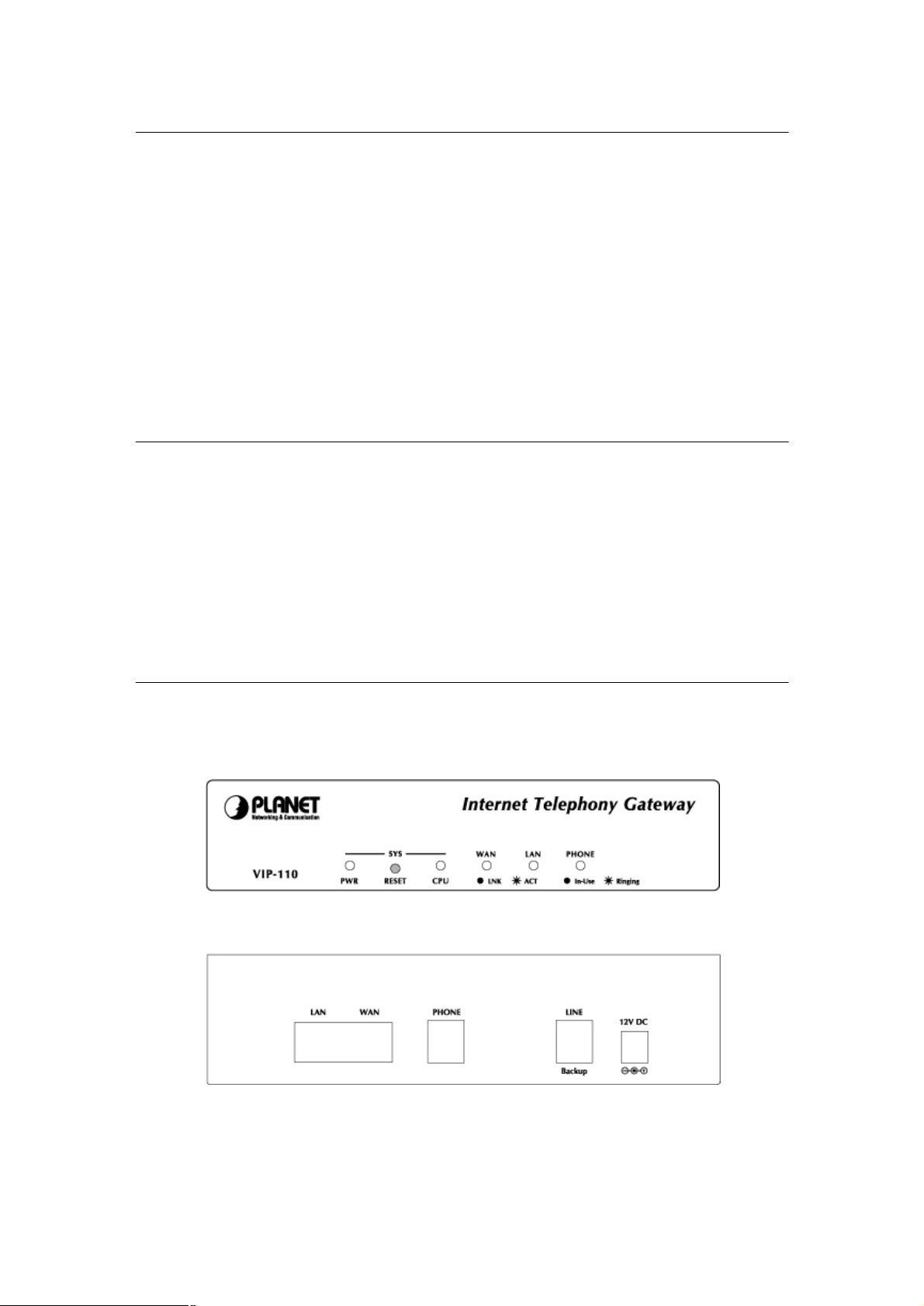
Physical Details
The front panel of VIP-110/VIP-210 contains a push button and 5/6 LED indicators. The following
figure illustrates the front/rear panel of VIP-110/VIP-210.
VIP-110 Front Panel
VIP-110 Rear Panel
- 6 -
Page 7
PLANET VIP-110/VIP-210 Web Configuration Guide
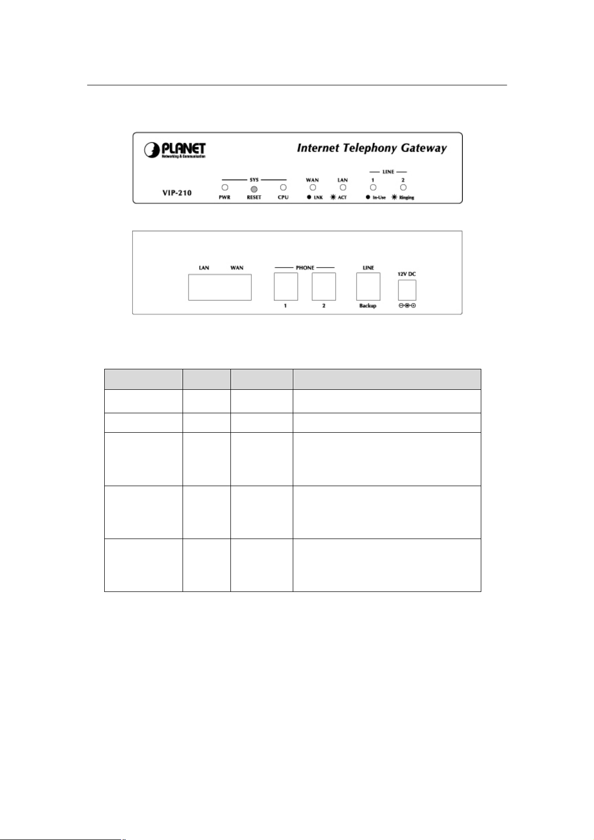
VIP-210 Front Panel
VIP-210 Rear Panel
LED Display & Button
Indicator Color Activity Indication
PWR Green On Power is supplied to the gateway.
CPU Green Blinking The system is running. (Heartbeat LED)
LAN
Ÿ ACT
Ÿ LNK
WAN
Ÿ ACT
Ÿ LNK
PHONE/LINE
Voice Channels
Green
Green
Green
Green
Green Off
On
On
On
On
On
Blinking
Data is presented on LAN.
The gateway is connected to LAN.
Data is presented on WAN.
The gateway is connected to WAN.
The line is idle.
The line is being used.
The line is ringing.
Physical Interfaces
VIP-110/VIP-210 is equipped with a WAN interface with 10/100 Mbps auto-negotiation capability, 1
LAN Ethernet ports with 10/100 Mbps auto-negotiation capability. In addition to the LAN/WAN
Ethernet interface ports, One (VIP-110) / two (VIP-210) RJ-11 telephony interface ports on the rear
panel. Their functions are described below:
- 7 -
Page 8

PLANET VIP-110/VIP-210 Web Configuration Guide
Connecting VIP to a 10/100 Mbps Ethernet
Connecting VIP to a 10/100 Mbps Ethernet
network / xDSL /Cable modem for Internet
Connect PBX Extension line/Telephone to VIP
Port Label Function
RJ-45 LAN
network
RJ-45 WAN
access
RJ-11 Telephony
for voice communication
Reset Button
There is a push button located behind a small hole next to the PWR LED. This button allows you
to reset VIP or force VIP to enter firmware upgrade mode.
Reset
Push a small, stiff object into the hole until the SYSTEM LED stops blinking, then release the
button.
- 8 -
Page 9

PLANET VIP-110/VIP-210 Web Configuration Guide
Physical Installation and IP Configuration
This chapter illustrates basic installation of VIP-110/VIP-210
Physical Installation Requirement
• Network cables. Use standard 10/100BaseT network (UTP) cables with RJ45 connectors.
• TCP/IP protocol must be installed on all PCs.
For Internet Access, an Internet Access account with an ISP, and either of a DSL or Cable modem
(for WAN port usage)
Procedure
1. Choose an Installation Site
Select a suitable place on the network to install VIP–110/VIP-210.
Ensure VIP–110/VIP-210 and the DSL/Cable modem are powered OFF.
2. Connect LAN Cables
Use standard LAN cables to connect PCs to the Switching Hub ports on VIP–110/VIP-210.
•
Both 10BaseT and 100BaseT connections can be used simultaneously.
• If required, you can connect any LAN port to another Hub. Any LAN port on
VIP–110/VIP-210 will automatically function as an "Uplink" port when required. Just
connect any LAN port to a normal port on the other hub, using a standard LAN cable.
3. Connect WAN Cable
Connect the DSL or Cable modem to the WAN port on VIP–110/VIP-210. Use the cable
supplied with your DSL/Cable modem. If no cable was supplied, use a standard cable.
4. Power Up
• Power on the Cable or DSL modem.
• Connect the supplied power adapter to VIP–110/VIP-210 and power up.
Use only the power adapter provided. Using a different one may cause hardware damage
- 9 -
Page 10

PLANET VIP-110/VIP-210 Web Configuration Guide
Connection of incorrect telephony devices to the ports on
the TIM can cause permanent damage to the TIM and/or VIP.
ë
5. Check the LEDs
The PWR LED should be ON.
•
• The CPU LED should flash.
• For each LAN (PC) connection, the LAN LNK/ACT LED should be ON (provided the PC is
also ON.)
The WAN LED should be ON.
•
6. Connecting to the telephony devices
VIP-110/VIP-210 supports one types telephony the FXS (Foreign eXchange Station). FXS
interface is used to connect to regular analog telephone sets or FAX machine
Note
Administration Interface
PLANET VIP-110/VIP-210 provides CLI (Command Line Interface), and GUI (Web based,
Graphical User Interface) for machine management and administration.
Web configuration access
To start VIP-110/VIP-210 web configuration, you must have one of these web browsers installed
on computer for management
• Netscape Communicator 4.03 or higher
•
Microsoft Internet Explorer 4.01 or higher with Java support
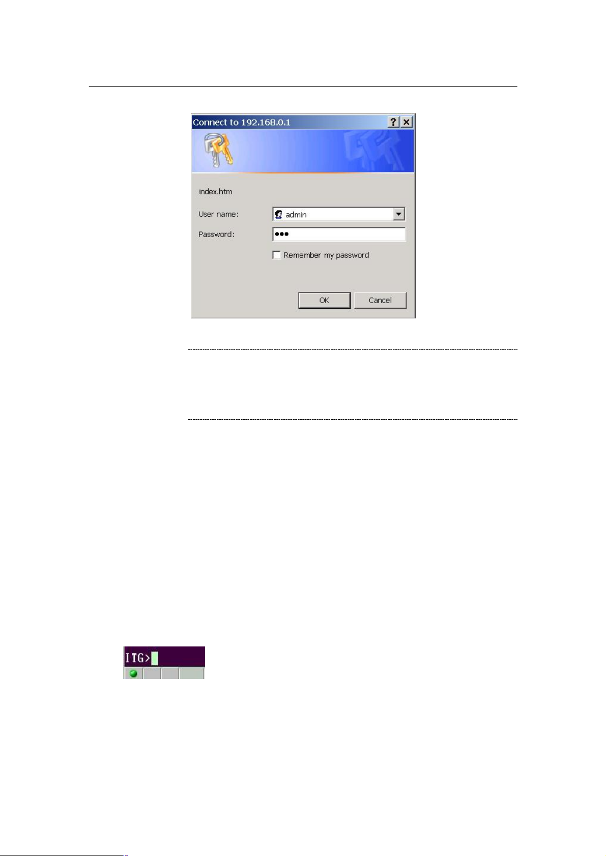
Default LAN interface IP address of VIP-110/VIP-210 is 192.168.0.1. You may now open your web
browser, and insert 192.168.0.1 in the address bar of your web browser to logon VIP-110/VIP-210
web configuration page.
VIP-110/VIP-210 will prompt for logon username/password, please enter: admin / 123 to continue
machine administration.
:
- 10 -
Page 11
PLANET VIP-110/VIP-210 Web Configuration Guide
ë
210. If you’re not familiar
manual CD or consult your network administrator for proper
Note
CLI configuration access
• You can connect the VIP-110/VIP-210 via telnet terminal program
• Start up your terminal program, here, we use Hyper Terminal as the example.
• Set up the parameters as below for Telnet connection
Host Address: 192.168.0.1
Port Number: 23
Connect Using: TCP/IP (WinSock)
• When connected, you’ll be asked to insert the username/password for machine admini-
stration, please enter “admin/123” for authentication. After logging in, the terminal will
prompt “ITG>” to indicate your machine is now ready for operation.
Please locate your PC in the same network segment
(192.168.0.x) of VIP-110/VIPwith TCP/IP, please refer to related chapter on user’s
network configurations.
:
- 11 -
Page 12

PLANET VIP-110/VIP-210 Web Configuration Guide
cannot get any response from the terminal program
” key several times. Please check the
by your PC. Then check the
etwork parameters are
correctly configured, it is recommended to check if the
ë
ITG>net set lan ip 192.168.0.1<enter>
In general cases, the LAN IP address is the default gateway
of LAN side workstations for Internet access, and the WAN
the IP address for remote calling
i
Note
If you
after strike “Enter
TCP/IP configurations of your computer, i.e. the destination VIP should be reachable
parameters above again. If all the n
network cabling is secure.
LAN/WAN Interface quick configurations
Nature of PLANET VIP-110/VIP-210 is an IP Sharing (NAT) device, it comes with two default IP
addresses, and default LAN side IP address is “192.168.0.1”, default WAN side IP address is
“172.16.0.1”. You may use any PC to connect to the LAN port of VIP-110/VIP-210 to start machine
administration.,
Hint
IP of VIP-110/VIP-210 is
party to connect with.
LAN IP configuration via command line interface (CLI)
Here we’d like to configure the IP address of VIP-110/VIP-210 LAN interface, LAN IP address
related commands are:
ITG>net set lan
net set lan ip <addr>
net set lan mask <mask>
ITG>
• The command “net set lan ip” is used to set the IP address of VIP. If you would like to set
up the IP address to “192.168.0.1”, for example. You can have the command as below and
press the <Enter> key:
- 12 -
Page 13

PLANET VIP-110/VIP-210 Web Configuration Guide
• The command “net set lan mask” is used to set the network mask of VIP. If you would like
to set up the network mask to “255.255.255.0”, for example. You can have the command
as below and press the <Enter> key:
ITG>net set lan mask 255.255.255.0
You’ll need to save the configured LAN IP address, network mask value into machine via
command: net store , then insert command: net reset to reboot machine and make thechanges
effective.
- 13 -
Page 14
PLANET VIP-110/VIP-210 Web Configuration Guide
Preparation before beginning web administration on
VIP-110/VIP-210
In this section, we’ll introduce steps of how to setup a PC to communicate with VIP-110/VIP-210
and Internet access related parameters through TCP/IP protocol configuration.
Before starting web browser to connect to VIP-110/VIP-210, please check TCP/IP configurations
on PC: the PC must be configured either as a DHCP client and or fixed IP allocation on the intranet
or Internet. After ensuring TCP/IP configuration on the managing workstation, you may connect to
web administration page of VIP-110/VIP-210 either from intranet, or Internet
Following are guidelines of setting up TCP/IP configurations on different OS platform
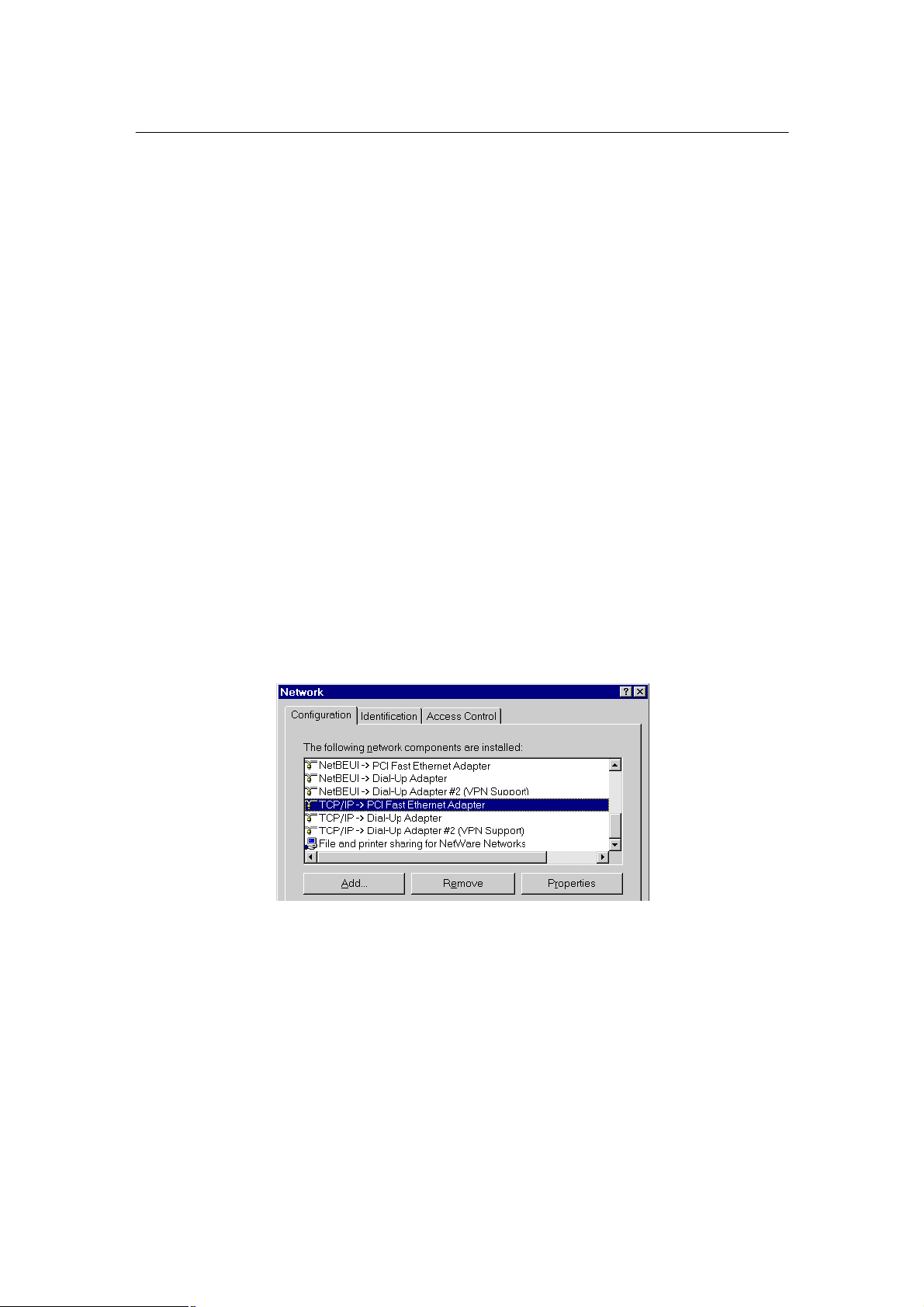
Checking TCP/IP settings on Windows 95/98
If there is no TCP/IP installed on your Windows 95 or Windows 98, you must add the protocol and
change the settings on your PC.
Step 1 Open the Control Panel, and double-click the Network icon. The Network window appears
Step 2 If TCP/IP protocol shown in the network window, please continue to the next step. If it
is not shown, please add TCP/IP protocol support as follows:
a. Click Add.
b. Double-click Protocol in the Select Network Component Type window, then
the Select Network Protocol window appears.
c. Choose Microsoft for the manufacturer.
d. Choose TCP/IP for the network protocol.
- 14 -
Page 15
PLANET VIP-110/VIP-210 Web Configuration Guide
e. Click OK, and the Network window appears.
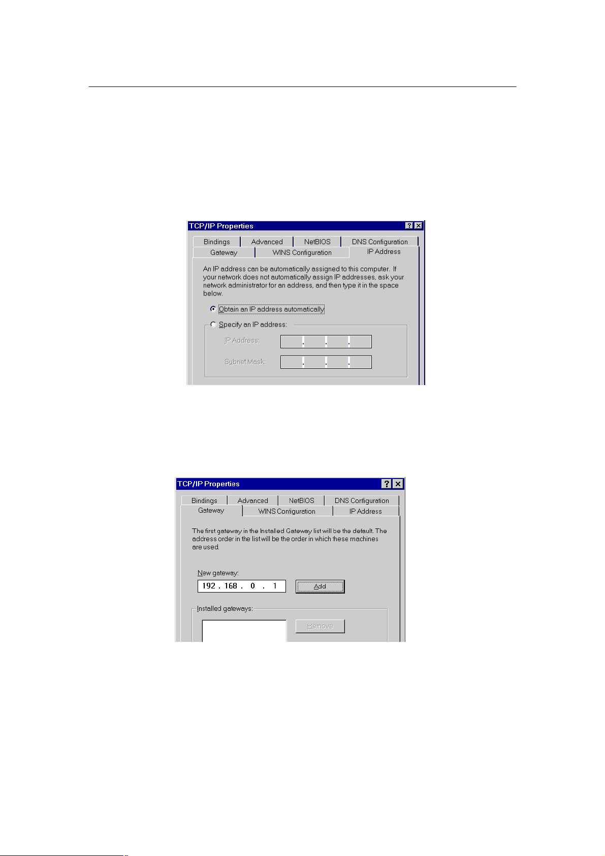
Step 3.1
Change the TCP/IP settings to use DHCP as follows (DHCP environment):
a. Double-click the first TCP/IP cable icon. The TCP/IP Properties window appears.
b. Verify that the IP Address tab has Obtain an IP address automatically selected
and that the IP Address and Subnet Mask fields are grayed out.
Step 3.2 Change the TCP/IP settings to use DHCP as follows (Fixed IP allocation):
If there is no DHCP server in your network, please consult your network administrator
the TCP/IP parameters of your PC, and insert the obtained data in IP address tab. To
access different IP segment (for example, from LAN to Internet), you will need to assign the gateway and DNS (for Internet access) in your PC.
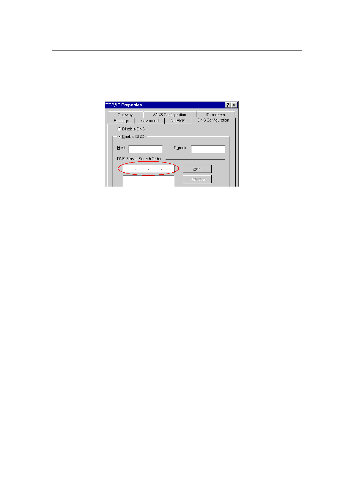
Step 5 Add the DNS server given to you by your ISP or network administrator:
a. Click the DNS Configuration tab.
b. Click Enable DNS.
c. Enter your host name in the Host field.
- 15 -
Page 16
PLANET VIP-110/VIP-210 Web Configuration Guide
d. Enter your domain name in the Domain field.
e. Enter the IP address of the DNS server in the DNS Server Search Order field.
f. Click Add. The IP address displays in the window below the field.
Step 5 Click OK, and reboot machine to make the modifications effective in your PC.
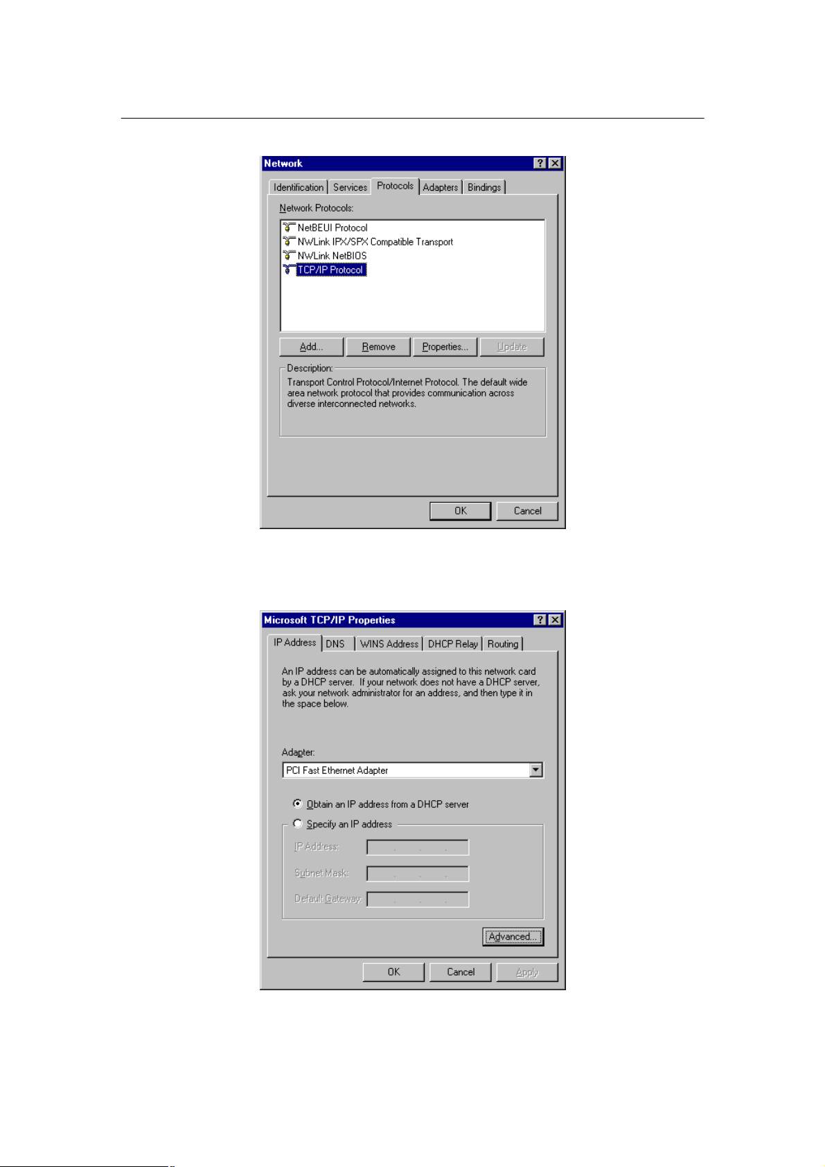
Checking TCP/IP settings on Windows NT
Obtain an IP address from a DHCP Server
Select Control Panel - Network, and, on the Protocols tab, select the TCP/IP protocol, as shown
below.
- 16 -
Page 17
PLANET VIP-110/VIP-210 Web Configuration Guide
Windows NT4.0 - TCP/IP
a) Click the Properties button to see a screen like the one below.
Windows NT4.0 - IP Address
- 17 -
Page 18

PLANET VIP-110/VIP-210 Web Configuration Guide
b) Select the network card for your LAN.
c) Select the appropriate radio button - Obtain an IP address from a DHCP Server or Specify an IP
Address, as explained.
Specify an IP Address
If your PC is already configured with an IP address, check with your network administrator before
making the following changes.
a) The Default Gateway must be set to match your network environment. To set this:
Click the Advanced button on the screen above.
•
• On the following screen, click the Add button in the Gateways panel, and enter gateway IP
address, as shown below.
• If necessary, use the Up button to make the inserted on the first entry in the Gateways list.
Windows NT4.0 - Add Gateway
b) The DNS should be set to the address provided by your ISP, as follows:
• Click the DNS tab.
On the DNS screen, shown below, click the Add button (under DNS Service Search Order),
•
and enter the DNS provided by your ISP.
- 18 -
Page 19

PLANET VIP-110/VIP-210 Web Configuration Guide
Windows NT4.0 - DNS
- 19 -
Page 20

PLANET VIP-110/VIP-210 Web Configuration Guide
Checking TCP/IP Settings - Windows 2000:
Select Control Panel - Network and Dial-up Connection.
a) Right - click the Local Area Connection icon and select Properties. You should see a
screen like the following:
Network Configuration (Win 2000)
b) Select the TCP/IP protocol for your network card.
c) Click on the Properties button. You should then see a screen like the following.
- 20 -
Page 21

PLANET VIP-110/VIP-210 Web Configuration Guide
TCP/IP Properties (Win 2000)
Ensure your TCP/IP settings are correct with one of the following description.
Using DHCP
To use DHCP, select the radio button Obtain an IP Address automatically. This is the default Windows setting. If your networking environment is a DHCP environment, Using this option is recom-
mended. Restart your PC to ensure it obtains an IP Address from DHCP server.
Using a fixed IP Address ("Use the following IP Address")
If your PC is already configured, check with your network administrator before making the following changes.
• Enter gateway IP address obtained from network administrator in the Default gateway field and
click OK. If the DNS Server fields are empty, select Use the following DNS server addresses, and
enter the DNS address obtained from network administrator or addresses provided by your
ISP, then click OK.
- 21 -
Page 22

PLANET VIP-110/VIP-210 Web Configuration Guide
Checking TCP/IP Settings - Windows XP
Select Control Panel - Network Connection.
a) Right - click the Local Area Connection icon and select Properties. You should see a
screen like the following:
Network Configuration (Windows XP)
b) Select the TCP/IP protocol for your network card.
c) Click on the Properties button. You should then see a screen like the following.
- 22 -
Page 23

PLANET VIP-110/VIP-210 Web Configuration Guide
TCP/IP Properties (Windows XP)
Ensure your TCP/IP settings are correct with one of the following description.
Using DHCP
To use DHCP, select the radio button Obtain an IP Address automatically. This is the default Windows setting. If your networking environment is a DHCP environment, Using this option is recom-
mended. Restart your PC to ensure it obtains an IP Address from DHCP server.
Using a fixed IP Address ("Use the following IP Address")
If your PC is already configured, check with your network administrator before making the following changes.
Enter gateway IP address obtained from network administrator in the Default gateway field and
click OK. If the DNS Server fields are empty, select Use the following DNS server addresses, and
enter the DNS address obtained from network administrator or addresses provided by your ISP,
then click OK.
- 23 -
Page 24

PLANET VIP-110/VIP-210 Web Configuration Guide
d parameters
210
is the only DHCP server in the network segment to ensure
i
LAN IP address configuration via web configuration interface
Execute your web browser, and insert the IP address (default: 192.168.0.1) of VIP in the adddress
bar. After logging on machine with username/password (default: admin / 123), browse to “Internet
Access Setup” --> “LAN” configuration menu:
Parameter Description
IP address LAN IP address of VIP
Default: 192.168.0.1
Subnet Mask, LAN mask of VIP-110/VIP-210
Default: 255.255.255.0
DHCP server Config
Number of DHCP VIP-110/VIP-210 is capable of working as a DHCP server, the DHCP client num-
ber is the
Client allowed DHCP clients in its network.
Default: 30
Start address Beginning IP address of DHCP client IP assignment.
Default: 192.168.0.10
Hint
It is suggested to keep the DHCP server relate
in default state to keep machine in best performance.
If the DHCP server enabled, please make sure VIP-110/VIP-
machine smooth operations.
After confirming the modification you’ve done, machine will show prompt in the message window.
- 24 -
Page 25

PLANET VIP-110/VIP-210 Web Configuration Guide
particular Hostname, Domain
IP Address allocated to you,
,
to obtain proper PPPoE/IP
If Internet connection cannot be established, please check
the physical connection or contact the ISP service staff
Please click on the REBOOT link to restart machine to macke the changes effective,
WAN IP address configuration via web configuration interface
Execute your web browser, and insert the IP address (default: 192.168.0.1) of VIP in the adddress
bar. After logging on machine with username/password (default: admin / 123), browse to “Internet
Access Setup” --> “WAN” configuration menu, you will see the configuration screen below:
i
Hint
Connection Type Data required.
Usually, none.
But some ISP may require a
DHCP client
name, or MAC (physical)
address.
Fixed IP Address
PPPoE / PPTP
Please consult your ISP personnel
address related information, and input carefully.
for support information.
and related information.
PPPoE: Login name/password
service name (optional).
PPTP: Server IP Address
- 25 -
Page 26

PLANET VIP-110/VIP-210 Web Configuration Guide
Internet Access Setup
Ÿ When WAN interface of VIP-110/VIP-210 is properly configured, with default Windows
TCP/IP settings, no changes need to be made on LAN side PC for Internet access.
• If using a specified (fixed) IP address on your PC, refer to the user manual for details of the required
changes:
• The Gateway must be set to the IP address of VIP-110/VIP-210
The DNS should be set to the address provided by your ISP.
•
For Windows 9x/ME/2000
Ÿ Select Start Menu - Settings - Control Panel - Internet Options.
Ÿ Select the Connection tab, and click the Setup button.
Ÿ Select "I want to set up my Internet connection manually, or I want to connect through a
local area network (LAN)" and click Next.
Ÿ Select "I connect through a local area network (LAN)" and click Next.
Ÿ Ensure all of the boxes on the following Local area network Internet Configuration
screen are unchecked.
Ÿ Check the "No" option when prompted "Do you want to set up an Internet mail account
now?".
Ÿ Click Finish to close the Internet Connection Wizard.
Setup is now completed.
For Windows XP
Ÿ Select Start Menu - Control Panel - Network and Internet Connections.
Ÿ Select Set up or change your Internet Connection.
Ÿ Select the Connection tab, and click the Setup button.
Ÿ Cancel the pop-up "Location Information" screen.
Ÿ Click Next on the "New Connection Wizard" screen.
Ÿ Select "Connect to the Internet" and click Next.
Ÿ Select "Set up my connection manually" and click Next.
Ÿ Check "Connect using a broadband connection that is always on" and click Next.
- 26 -
Page 27

PLANET VIP-110/VIP-210 Web Configuration Guide
command from command prompt to get response from an Internet
i
Hint
If you’re unable to get response from the remote site, please
is
" command:
If no response is received, either the connection is not
working, or your PC's IP address is not compatible with
is using a fixed IP Address, its IP Address must be
within the range 192.168.0.2 to 192.168.0.254 to be compatible
210's default IP Address of 192.168.0.1. Also,
the Network Mask must be set to 255.255.255.0.Ensure that your
210 are on the same network segment. (If you
Click Finish to close the New Connection Wizard. Setup is now completed.
To verify the Internet connection, you may start ping
node/site.
Hint
i
check the following:
VIP-110/VIP-210 is properly installed, LAN connection
OK, and it is powered ON.
You can test the connection by using the "ping
ping 192.168.0.1
VIP-110/VIP-210's IP Address.
If your PC
with VIP-110/VIP-
PC and VIP-110/VIPdon't have a router, this must be the case.)
- 27 -
Page 28

PLANET VIP-110/VIP-210 Web Configuration Guide
WEB CONFIGURATION
Configuring and monitoring your VIP-110/VIP-210 from web browser
The VIP-110/VIP-210 integrates a web-based graphical user interface that
can cover most configurations and machine status monitoring. Via standard,
web browser, you can configure and check machine status from anywhere around
the world.
Overview on the web interface of VIP-110/VIP-210
With web graphical user interface, you may have:
w More comprehensive setting feel than traditional command line interface.
w Provides user input data fields, check boxes, and for changing machine configu-
ration settings
w Displays machine running configuration
To start VIP-110/VIP-210 web configuration, you must have one of these web browsers
installed on computer for management
w Netscape Communicator 4.03 or higher
w Microsoft Internet Explorer 4.01 or higher with Java support
- 28 -
Page 29

PLANET VIP-110/VIP-210 Web Configuration Guide
Manipulation of VIP-110/VIP-210 via web browser
Log on VIP-110/VIP-210 via web browser
After TCP/IP configurations on your PC, you may now open your web browser, and input
192.168.0.1 to logon VIP-110/VIP-210 web configuration page.
VIP–110/VIP-210 will prompt for logon username/password: admin / 123
VIP-110/VIP-210 logon page
(Log on VIP-110/VIP-210 via username/password: admin /123 )
VIP-110/VIP-210 main page
- 29 -
Page 30

PLANET VIP-110/VIP-210 Web Configuration Guide
Start administration
When you browse the left control panel in VIP-110/VIP-210 web configuration, the main function
menus are listed in the left control panel: internet Access Setup, Dialplan Setup, H.323 Settings, Tools,
Advanced Configuration and Help Menus. These major configuration menus have related
sub-menus and parameters, following sections will give you an overall illustration of the functionality in VIP-110/VIP-210.
Internet Access Setup
There are two sub configuration menus in this category:
i. LAN
The LAN configuration menu is used to configure LAN IP address, and DHCP server related information in VIP-110/VIP-210.
Parameter Description
IP address LAN IP address of VIP
Default: 192.168.0.1
Subnet Mask, LAN mask of VIP-110/VIP-210
Default: 255.255.255.0
DHCP server Config
Number of DHCP VIP-110/VIP-210 is capable of working as a DHCP server, the DHCP client num-
ber is the
Client allowed DHCP clients in VIP-110/VIP-210’s network.
- 30 -
Page 31

PLANET VIP-110/VIP-210 Web Configuration Guide
Default: 30
Start address Beginning IP address of DHCP client IP assignment.
Default: 192.168.0.10
ii. WAN
Four connection types supported in VIP-110/VIP-210: PPPoE/PPTP, Fixed IP, and DHCP
PPPoE/PPTP screen
VIP-110/VIP-210 natively integrates with PPPoE client, this makes VIP-110/VIP-210 is able to
establish Internet connection via popular ADSL access. The PPPoE/PPTP configuration menu is
used to configure and PPTP related information in VIP-110/VIP-210.
Parameter Description
Enable PPPoE Enable or disable PPPoE client in VIP-110/VIP-210
Default: PPPoE client in VIP-110/VIP-210 is disabled
Service name Some ISP may require a particular service name for Internet access, this field is
optional. Please contact your ISP for detail information of this parameter.
Username User name for PPPoE connection
- 31 -
Page 32

PLANET VIP-110/VIP-210 Web Configuration Guide
your ISP personnel to obtain proper PPPoE
210
or contact the ISP service staff for support information.
Default: null
Password Password for PPPoE connection
Default: null
Idle Timeout Enter a Maximum Idle Time (in minutes) to define a maximum period of time for
which the Internet connection is maintained during inactivity. If the connection is
inactive for longer than the Maximum Idle Time, then it will be dropped.
Default: null
IPCP Fixed IP Certain ISP provides a fixed IP address to each of its subscriber. This parameter
allows users to setup the fixed IP address assigned by ISP for the PPPoE connection.
Default: 0.0.0.0
Authentication VIP-110/VIP-210 implements two types of authentication protocol. This parameter
is
protocol used for specifying which authentication protocol VIP will use to send authentica-
tion message to the server.
Default: pap
Transmission VIP-110/VIP-210 implements a bandwidth regulation algorithm over its PPPoE
interface.
bandwidth This algorithm is enabled, when PPPoE client is enabled, for guaranteeing enough
bandwidth is reserved for voice packets
Default: 0
Enable PPTP Enable or disable built-in PPTP client
Default: disabled.
PPTP Server If ISP demands for PPTP connection, please insert PPTP server IP address here.
Address
Please consult
related information, and input carefully.
i
Hint
If Internet connection cannot be established, please
double-check the parameters configured in VIP-110/VIP-
- 32 -
Page 33

PLANET VIP-110/VIP-210 Web Configuration Guide
subfiled ranging from 0
Fixed IP screen
Parameter Description
IP address Static (Fixed) WAN IP address of VIP-110/VIP-210
Default: 172.16.0.1
Subnet Mask WAN interface network mask of VIP-110/VIP-210
Default: 255.255.0.0
Default Gateway Default gateway of VIP-110/VIP-210 WAN interface
Default: 0.0.0.0
Primary DNS server First DNS server used for Internet domain name resolution
Default
Secondary If the primary DNS server cannot perform domain name resolution,
VIP-110/VIP-210
DNS server will utilize this server for name resolution. This parameter is optional.
Default: 0.0.0.0
IP ToS VIP-110/VIP-210 allows users to set the 8-bit Service Type field in the IP header
: 0.0.0.0
for all the
packets it sends across the WAN interface. The Service Type field is divided into
five subfields, among which four subfileds are user configurable. This command is
used to set these subfields.
ip_preced
The 3-bit PRECEDENCE
- 33 -
Page 34

PLANET VIP-110/VIP-210 Web Configuration Guide
peripherals, such as the router, network switch… etc. Please
i
Please consult your network administrator or ISP personnel
have item while
i
through 7.
d
t
r
Default: 0 0 0 0
Hint
of DNS server IP address for best performance in name
resolution. The DNS parameter is a mustmaking a domain name call.
Hint
IP ToS field required cooperation from other network
contact your network administrator for proper configurations
The D bit subfield, either 0 or 1.
The T bit subfield, either 0 or 1.
The R bit subfield, either 0 or 1.
DHCP screen
Parameter Description
DHCP client Enable or disable DHCP client function in VIP-110/VIP-210
Default: DHCP client in VIP-110/VIP-210 is disabled
Router name If your ISP demands a particular Hostname/router name for
- 34 -
Page 35

PLANET VIP-110/VIP-210 Web Configuration Guide
connection setup, please insert the parameter here.
Default: null
MAC address If using a Cable modem, your ISP may have recorded the MAC (physical) address
Cloning of your PC. Enable the " MAC address Cloning" and fill the desired workstation
MAC address in the following parameter to establish Internet access.
Default: off
Cloned Some ISPs may require you to use MAC (physical) address for Internet connection.
MAC address Please enter the MAC address of network interface card on workstation here.
Default: MAC address of WAN interface on VIP-110/VIP-210.
- 35 -
Page 36

PLANET VIP-110/VIP-210 Web Configuration Guide
Dial Plan Management
Dial plan in VIP-110/VIP-210 is a database, which contains the Address
Translation and Parsing Manager (ATPM) to looks up for translating a dial
string to a calling destination. The dial plan management menu allows you
to modify and display the dial plan.
Dial plan Concept
Before you start setting up the dial plan in VIP-110/VIP-210, following basic concept associated
with the dialplan in VIP-110/VIP-210 should be explained in advance.
Address Table
Ÿ
Phone number
Ÿ
Hunt Group ID
Ÿ
Destination ID
Ÿ
Destination
Ÿ
Address Table
The address table maps a phone number to a hunt group. The table contains entries that specify
the following information:
Ÿ Telephone number
Ÿ The hunt group the phone number maps to.
The minimum number of digits to collect before the ATPM starting
Ÿ
address lookup.
Ÿ The maximum number of digits the ATPM collects before it considers
the dial string is complete.
Ÿ Number of digits forward to the destination.
Phone Number
The “Phone number” in the VIP is a set of digits. You can setup it to have better migration with
your original system. This number will only map to one Hunt Group.
Number
One
‘201’
è
To
‘1’
è
Hunt Group
One
- 36 -
Page 37

PLANET VIP-110/VIP-210 Web Configuration Guide
Hunt Group
The “Hunt Group” here is an interpreter between phone number and Destination ID. VIP phone
table will base on the number you dialed to find the related hunt group. So, different numbers
can map to the same hunt group.
Number
Many
è
Hunt Group
To One
‘201’
‘0201’
è
‘1’
Hunt Group can map to different destinations. This function can be used if the first destination is
busy. Once a busy tone is found, VIP will automatically goes to the second Destination, then
third, etc..
Hunt Group
è
One To
‘1’
è
Destination ID
Many
‘1’
‘9’
Destination ID and Destination
The “Destination ID” here is an interpreter between Hunt Group and physical Destination.
Hung Groups can map to the same destination ID.
Hunt Group
è
Destination ID
Many To
One
‘1’
‘5’
è
‘1’
The destination here is the physical port that VIP should calls to. There are two types of
physical destination.
Ÿ A physical port on VIP, i.e. the FXO/FXS port
Ÿ A H.323 VoIP gateway with a fixed IP or a fixed host name.
Destination ID
One To
‘1’
‘10’
è
Destination
One
è
è
‘vip.planet.com.tw’
‘0’
- 37 -
Page 38

PLANET VIP-110/VIP-210 Web Configuration Guide
Add, Delete, Find, or
Add, Delete, Find, or
,
Add, Delete, Find, or
numbers, hunt groups, and
destinations settings, for
Restore Dial Plan
while temporary settings
Stores all settings that
Dial plan/Dial setting Screen
Dial Settings
Clear Dial Plan
The Setup screen of the
Dial Plan including:
• Telephone Settings,
which allows one to
List telephone numbers.
Hunt Group Settings,
•
which allows one to
List hunt group settings
• Destination Settings
which allows one to
List destination
settings
Clears all telephone
both old and new ones
Retrieves all dial plan
settings from the flash
Store to NVRAM
will be cleared
you have specified permanently
- 38 -
Page 39

PLANET VIP-110/VIP-210 Web Configuration Guide
Telephone number to match. This is only part of
For each hunt group ID, you need to assign it
Minimum number of digits to be collected before
the ATPM starting matching the dial string with
ber of digits to be collected before
the ATPM starting matching the dialed string
beginning of the collected dial string before
Phone number setting screen
You may modify VIP telephone address table here: you may add (delete, find or list) desired
telephone number mapping to hunt group at this menu.
Telephone
Number
Hunt Group ID
the total dialed string.
a unique identifier between 0 and 99.
Min. Digits
Max. Digits Maximum num
entries in the address table.
Strip Length The number of digits to be stripped at the
with entries in the address table.
Append Prefix (Optional) Digit to be added before the be-
forwarding the string to the destination.
ginning of the collected dial string before
forwarding it to the destination.
- 39 -
Page 40

PLANET VIP-110/VIP-210 Web Configuration Guide
Hunt Group setting screen
You may modify VIP telephone hunt group table here: you may add (delete, find or list) desired
hunt group at this menu.
We can add (delete, find or list) desired hunt group ID mapping to destination ID at this menu. If
you want to make the port calls to the secondary receiver, you can click one “More Destinations”
you can then add the second, third receiver if the desired port/phone is busy.
Destination setting screen
You may modify VIP telephone destination table here. There are three kinds of destination in the
selection table: One is Remote Destination IP, one is Remote Host Name and the other is Local
Destination Channel.
- 40 -
Page 41

PLANET VIP-110/VIP-210 Web Configuration Guide
Save to NVRAM setting Screen
After Dialplan configurations, you may save the modifications in this menu
Clear Dialplan setting screen
You may clear all the existing dialplan configurations and restore default dialplan configurations in
this menu; however, the “clear” action will not take effects until this action is saved into machine via
the “Save to NVRAM” link.
Restore Dialplan setting screen
If the “Restore the Dialplan” button is pressed, all the temporary (not saved) dialplan modifications
will be lost.
- 41 -
Page 42

PLANET VIP-110/VIP-210 Web Configuration Guide
If you’re not familiar with dialplan configurations, you
i
Hint
may directly click on the dialplan help menu for more
information.
Dialplan Help Menu Screen
- 42 -
Page 43

PLANET VIP-110/VIP-210 Web Configuration Guide
H.323 Configurations
There are three sub configuration menus: General H.323 configuration, Gatekeeper, and H.323
Alias configurations in this category:
i. General H.323 Configuration
VIP-110/VIP-210 H.323 configuration page is used to configure H.323 parameters, these parameters are designed to meet most calling environment.
Parameter Description
Display Name This field is to set the display name information that is carried in the H.323 setup
messages. Up to 48 characters can be entered.
Default: customer
Terminal Type This field is to set the H.245 terminal type, which is used as part of the mas-
ter/slave determination process of H.245. Typically, setting a value of less than 50
will force slave operation, and a value of greater than 200 will force the master
operation.
Default: 60
RTP Port Base This field is to select the starting port number for assignment of RTP and RTCP
ports. According to the H.323 specification, RTP port number should be even in
value, and the RTCP port number should be one greater than the RTP port. Typically, numbers from 0 to 1023 are reserved on most systems.
- 43 -
Page 44

PLANET VIP-110/VIP-210 Web Configuration Guide
meters
nication toward destination call party, please consult ITSP
Default: 30000
Outgoing Fast Start This field is to enable or disable the Fast start mode on the outgoing side of the
call.
Default: off
Incoming Fast Start This field is to enable or disable the Fast start mode on the incoming side of the
call.
Default: off
NAT_Call Mode Enables resolve proper calling address from remote sites, which use NAT routers
with private IP networks behind.
Default: on
Default DTMF Mode There are two ways VoIP gateway handles DTMF relay, per H.323 and IMTC
specifications.
Default: H323 V2 Signal
Call Signaling port Allows users to select TCP port which H.225 listens for incoming call setup
request.
Default: 1720
Hint
i
It is strongly recommended not to modify these para
on your own. If you met difficulty to establish commu-
engineering staff, experienced personnel or local distributor support staff for proper configuration.
- 44 -
Page 45

PLANET VIP-110/VIP-210 Web Configuration Guide
ii. H.323 Gatekeeper Configuration
Parameter Description
Gatekeeper Enable or disable H.323 Gatekeeper function in VIP-110/VIP-210
Operation
Default: Gatekeeper mode in VIP-110/VIP-210 is disabled
Gate Keeper Specify the gatekeeper address when configured to manual mode. When auto mode
Address is desired, this field should be set to auto.
Allow Calls This field is to inform the H.323 stack to allow calls when the
Without Gate endpoint is not registered with a gatekeeper.
Keeper
Default: true
Registration Type This field is to set the endpoint registration type. This specifies how the endpoint
will register itself with the gatekeeper.
Default: gateway
Max Registration This field is to control how many registration attempts will be made before the
Retries endpoint considers itself to have failed registration.
Default: 2
Time-to-Live When the VIP-110/VIP-210 registers to a gatekeeper, it specifies the duration of the
validity of the registration in the timeToLive field in the RRQ message it sends to
the gatekeeper. The gatekeeper may optionally change the timeToLive by returning
a different value in the RCF message it returns to VIP-110/VIP-210 This command
- 45 -
Page 46

PLANET VIP-110/VIP-210 Web Configuration Guide
Please do not modify these parameters without assistance
VoIP system administrator or ITSP personnel to obtain
care.
i
Hint
u’ve done in H.323 configuration
page require machine reboot to make the changes effective.
i
is for setting the timeToLive to be encapsulated in the RRQ message.
Default:0
endpoint_prefix This command is used to set the H.323 prefix that the VIP-110/VIP-210 will uses
when registering to an H.323 gatekeeper. After registering to a gatekeeper using the
prefix, the gatekeeper will map all Admission Request with destination matching
the prefix to VIP-110/VIP-210.
Default: null
Terminal ID One of the UUIEs in the H.323 Setup message that the VIP-110/VIP-210 sends to
a remote gateway when initiating a call is sourceAddress. The sourceAddress
UUIE is a list of alias addresses, by which the remote gateway identifies the
VIP-110/VIP-210. This command is used to set a string that the VIP-110/VIP-210
will place in the 1st alias address filed of the sourceAddress UUIE in the H.323
Setup message. This string is also placed in the 1st alias address filed in the terminalAlias filed in RRQ the gateways sends to the gatekeeper for registration.
Default: null
GateKeeper ID When the VIP-110/VIP-210 registers to a gatekeeper, it specifies the gatekeeper is
wishes to register with in the gatekeeperIdentifier field in the RRQ message it
sends to the gatekeeper. This command is for setting the string to be placed in the
gatekeeperIdentifier field in the RRQ message VIP-110/VIP-210 sends to gatekeeper.
Default: null
Hint
All the modifications yo
of a
proper Gatekeeper related information, and input with
- 46 -
Page 47

PLANET VIP-110/VIP-210 Web Configuration Guide
ii. H.323 Aliases Configuration
This command is used to create and delete aliases that are registered with the gatekeeper
- 47 -
Page 48

PLANET VIP-110/VIP-210 Web Configuration Guide
210 system administration password
curely to
in
server or allow a specific IP of Telnet
When receiving firmware upgrade from our web site
server containing the firmware file for firmware
ne running configurations in
You may select a specific voice channel (port) to
Tools Menu
VIP-110/VIP-210 provides a utility menu, which can adjust system-wide parameters, such as telnet
access, system password, firmware upgrade, and display of system configurations.
There are six sub configuration menus: Password Setup, Telnet Access, Firmware Upgrade, System
Status, H.323 Configuration Status, and Voice Port status.
Functionality in each submenu is shown below
VIP-110/VIP-
Password Setup
Telnet Access
Firmware Upgrade
System Status
H.323 Config.
Status
setup. Please keep the admin password se
prevent improper machine usage.
You may enable/disable VIP-110/VIP-210 builtTelnet
access.
or local distributor, you may prepare a TFTP
upgrade.
You may display machi
this page.
Machine H.323 running configuration can be
displayed in this page.
Voice Port Status
display parameters on this port.
- 48 -
Page 49

PLANET VIP-110/VIP-210 Web Configuration Guide
ers,
Virtual Server can be enabled
Similar to Virtual Server, port
cation here. If the application
ou could
restricted,
This free service is very useful
tual
users to connect to your Virtual
ers (or DMZ PC) using a URL,
lows
Internet access or service by
ltering"
Advanced Configuration menu
Advanced configuration menu in VIP-110/VIP-210 provides more Internet application compatibility
adjustment, which can eliminate inconvenience brought by the NAT algorithm.
There are six sub configuration menus: Virtual Servers, Port Forwarding, Special Application, DMZ,
Dynamic DNS, and Access Control.
Virtual Servers
If you’d like to share LAN
resource with Internet us
for this.
Port Forwarding
Special
Application
DMZ
Dynamic DNS
forwarding can reserve a
specific communication port
range for application.
Special Applications are any
Internet applications, which
normally cannot work through
the built-in firewall.
You can try defining appli-
can't be made to work, y
also try the "DMZ" feature.
DMZ can enable unbi-directional communication
for Internet applications.
when combined with the "Vir
Server" feature (or DMZ feature). DDNS allows Internet
Serv
rather than an IP Address.
Access Control feature al
administrators to restrict
Access Controls
individual workstations. The
process uses "Packet Fi
to block or discard data
packets.
- 49 -
Page 50

PLANET VIP-110/VIP-210 Web Configuration Guide
Help Menu
VIP-110/VIP-210 integrates online help menu, which can bring brief introduction of each feature in
machine. More information can be found in this user’s manual or the Command line Reference
guide.
You may click on the desired topic to view the help content
- 50 -
Page 51

PLANET VIP-110/VIP-210 Web Configuration Guide
201
202
You can also check LED indicators on VIP for telephony port
status. When an incoming call reaches VIP, the related LED
uld
i
Configuration Samples
Without any configuration, your VIP is come with following basic information.
Network:
WAN IP: 172.16.0.1, Mask: 255.255.255.0, Gateway: 0.0.0.0
LAN IP: 192.168.0.1, Mask: 255.255.255.0
Mask: 255.255.255.0
Dial Plan:
No. Hunt
Group
201 1 1 0 (local port #1)
202 2 2 1 (local port #2)
Base on this, if you have one VIP-210 with two FXS ports connect to two telephones, say port 1
and port 2, just pick up phone 1 and dial ‘202’, phone 2 should rings.
( G202 ð VIP ð local port #2ð (
FXS
Hint
Dest.
ID
should flash. And after picking up the handset, it sho
remains on and goes off after the phone is onhook.
Dest.
)))
VIP to VIP
The previous section shows you how to test your VIP without modify any settings. This section
we will shows you how to connect two VIP together and make the call.
Assume that we have a second ITG, called VIP B, which is a VIP-110 with default setting as well.
Now, let’s setup its WAN IP address to another, e.g. ‘172.16.0.2’ and connect it together to VIP
A with the following three steps.
Step 1.
On VIP B:
ITG>
net set wan ip 172.16.0.2
- 51 -
Page 52

PLANET VIP-110/VIP-210 Web Configuration Guide
ITG>net store
ITG>net reset <confirm prompt and restart machine>.
Step 2.
Step 3.
Connect WAN port of VIP A and VIP B to the same switch or hub, please make sure the
connection is ready.
On VIP A:
ITG>ping 172.16.0.2 ; ping to VIP B
Ping 172.16.0.2 success
1 out of 1 pings succeeded.
VIP B:
ITG>ping 172.16.0.1 ; ping to VIP A
Ping 172.16.0.1 success
1 out of 1 pings succeeded.
After the three steps, this means both VIP can find each other.
Now let’s setup a remote H.323 gateway to each other.
Dialplan setting on VIP A:
ITG>atpm req
ITG>atpm dadd 10 h323 172.16.0.2
ITG>atpm hadd 10 2 10
ITG>atpm aadd 02 0 5 10 2
ITG>atpm done
ITG>atpm store
Dialplan setting on VIP B:
ITG>atpm req
ITG>atpm dadd 10 h323 172.16.0.1
ITG>atpm hadd 10 2 10
ITG>atpm aadd 01 0 5 10 2
ITG>atpm done
ITG>atpm store
The dial plan of the two ITGs adds a new record after those commands.
- 52 -
Page 53

PLANET VIP-110/VIP-210 Web Configuration Guide
201
201
In the example, we assign each VIP with a unique number.
ier for users to think of it is as like an area
code. Each VIP represents a different area. VIP A is with
area code 01 and VIP B is with code 02. So, if you have more,
i
You are connects to a correct port. In this example, it
should be FXS port. And the phone number will be “20X”
mand “atpm aadd”
i
VIP A:
No. Hunt Group Dest. ID Dest.
02 10 10 172.16.0.2
VIP B:
No. Hunt Group Dest. ID Dest.
01 10 10 172.16.0.1
Now, once VIP A get a dialed number “02” it will direct to VIP B. The same to VIP B, ‘01’ will map
to VIP A without doubt.
VIP A
VIP-210
VIP B
Assume both VIPs have an analog telephone set connected to FXS port #0
To establish the voice communication between these units; .
VIP A:
Pick up handset and dial “02201”, where ‘02’ points to VIP B and ‘201’ for port 1 of VIP B. The
phone in VIP B should rings.
VIP B:
Pick up handset and dial “01201”, where ‘01’ points to VIP A and ‘201’ for port 1 of VIP A. The
phone in VIP A should rings.
Hint
Hint
It is eas
you can assign the next VIP with, 03, 04, etc.
If you cannot hear the ring, please do make sure:
1) Both VIP can ping each other
2)
where X follows the port.
Make sure you’ve strip the number in com
- 53 -
Page 54

PLANET VIP-110/VIP-210 Web Configuration Guide
After all of above, your VIP can work to each other.
- 54 -
 Loading...