

Page 1

802.11b/g Wi-Fi Phone
VIP-192
User’s manual
Version 1.0.0
1
Page 2

Copyright
Copyright (C) 2007 PLANET Technology Corp. All rights reserved.
The products and programs described in this User’s Manual are licensed products of PLANET Technology, This
User’s Manual contains proprietary information protected by copyright, and this User’s Manual and all
accompanying hardware, software, and documentation are copyrighted.
No part of this User’s Manual may be copied, photocopied, reproduced, translated, or reduced to any electronic
medium or machine-readable form by any means by electronic or mechanical. Including photocopying, recording,
or information storage and retrieval systems, for any purpose other than the purchaser's personal use, and without
the prior express written permission of PLANET Technology.
Disclaimer
PLANET Technology does not warrant that the hardware will work properly in all environments and applications,
and makes no warranty and representation, either implied or expressed, with respect to the quality, performance,
merchantability, or fitness for a particular purpose.
PLANET has made every effort to ensure that this User’s Manual is accurate; PLANET disclaims liability for any
inaccuracies or omissions that may have occurred.
Information in this User’s Manual is subject to change without notice and does not represent a commitment on the
part of PLANET. PLANET assumes no responsibility for any inaccuracies that may be contained in this User’s
Manual. PLANET makes no commitment to update or keep current the information in this User’s Manual, and
reserves the right to make improvements to this User’s Manual and/or to the products described in this User’s
Manual, at any time without notice.
If you find information in this manual that is incorrect, misleading, or incomplete, we would appreciate your
comments and suggestions.
CE mark Warning
The is a class B device, In a domestic environment, this product may cause radio interference, in which case the
user may be required to take adequate measures.
WEEE Warning
To avoid the potential effects on the environment and human health as a result of the presence of
hazardous substances in electrical and electronic equipment, end users of electrical and electronic
equipment should understand the meaning of the crossed-out wheeled bin symbol. Do not dispose of
WEEE as unsorted municipal waste and have to collect such WEEE separately.
Trademarks
The PLANET logo is a trademark of PLANET Technology. This documentation may refer to numerous hardware
and software products by their trade names. In most, if not all cases, their respective companies claim these
designations as trademarks or registered trademarks.
2
Page 3

Revision
User’s Manual for PLANET Wi-Fi Phone:
Model: VIP-192
Rev: 1.0 (2007, September)
Part No. EM-VIP192V1
3
Page 4

TABLE OF CONTENTS
Chapter 1................................................................................................ 8
Introduction............................................................................................ 8
Overview............................................................................................................................8
Package Content...............................................................................................................9
Physical Details.................................................................................................................9
Front view and keypad function:................................................................................9
Rear view and parts definition:.................................................................................10
Side view and parts definition:.................................................................................11
Normal Mode / Main Screen:...................................................................................11
Chapter 2 Preparations & Installation................................................ 12
Physical Installation Requirement................................................................................12
Installing the Battery:...............................................................................................12
Charging the Battery.................................................................................................12
Web Configuration access ........................................................................................13
Chapter 3 Menu Structure & Network Settings................................. 14
Menu Structure...............................................................................................................14
Network Settings.............................................................................................................15
Network Config........................................................................................................15
IP Settings................................................................................................15
DNS Settings ...........................................................................................17
Wireless ....................................................................................................................17
Scan APs..................................................................................................17
Manual Input ............................................................................................20
Preferred APs ..........................................................................................20
SIP Setting................................................................................................................22
SIP Account .............................................................................................23
SIP Server................................................................................................23
Outbound Proxy ......................................................................................23
Phone Port ...............................................................................................24
NAT Setting..............................................................................................................24
STUN & UPnP.........................................................................................25
Phone Port ...............................................................................................25
STUN Server ...........................................................................................25
Manual Config .........................................................................................26
NAT Keep Alive Time..............................................................................27
4
Page 5

Chapter 4.............................................................................................. 29
Phone book.......................................................................................... 29
Phone Book......................................................................................................................29
Create a New Contact...............................................................................................29
Browse......................................................................................................................30
Delete All..................................................................................................................31
Memory Status..........................................................................................................32
Chapter 5.............................................................................................. 33
Messaging............................................................................................ 33
Messaging Settings..........................................................................................................33
Voicemail..................................................................................................................33
SMS..........................................................................................................................34
New ...........................................................................................................34
Inbox .........................................................................................................35
Archive......................................................................................................35
Delete........................................................................................................36
Memory Status.........................................................................................36
E-Mail.......................................................................................................................37
Account.....................................................................................................37
POP3 Setting...........................................................................................38
SMTP Setting...........................................................................................38
Advance....................................................................................................39
Chapter 6.............................................................................................. 40
Call Log................................................................................................. 40
Call Log ...........................................................................................................................40
Chapter 7.............................................................................................. 41
Application........................................................................................... 41
Application......................................................................................................................41
Calendar....................................................................................................................41
Memo ........................................................................................................42
Select Date ..............................................................................................42
Delete All Memos ....................................................................................42
Memory Status.........................................................................................43
Calculator .................................................................................................................43
Chapter 8.............................................................................................. 44
Phone Settings..................................................................................... 44
Phone Settings.................................................................................................................44
Time & Date.............................................................................................................44
Language ..................................................................................................................44
Backlight Level ........................................................................................................45
5
Page 6

Ring Volume.............................................................................................................45
Voice Volume ............................................................................................................46
Alert T ype.................................................................................................................46
Wallpaper Management............................................................................................46
Ring tone Management.............................................................................................47
Hold tone Management ............................................................................................47
Power save................................................................................................................48
Change Password......................................................................................................48
Speed Dial ................................................................................................................49
Edit ............................................................................................................49
Browse......................................................................................................49
Chapter 9.............................................................................................. 50
Information........................................................................................... 50
Information.....................................................................................................................50
Chapter 10............................................................................................ 51
Call Function........................................................................................ 51
Call Function...................................................................................................................51
Do Not Disturb .........................................................................................................51
Call Waiting..............................................................................................................51
Anonymous Call.......................................................................................................52
Anonymous Reject ...................................................................................................52
Call Forward.............................................................................................................53
Unconditional ...........................................................................................53
Forward on Busy.....................................................................................53
Forward on No Answer ..........................................................................54
Chapter 11 ............................................................................................ 55
Using the web configuration .............................................................. 55
Using the web configuration..........................................................................................55
Accessing Configuration Menu................................................................................55
Web Login Setting....................................................................................................56
Restore Factory Setting ............................................................................................56
Firmware update.......................................................................................................57
Network Setting-DHCP............................................................................................57
Network Setting-Static IP.........................................................................................58
QoS Setting...............................................................................................................59
SIP Setting................................................................................................................59
SIP Account Settings ................................................................................................61
NAT T raversal Settings.............................................................................................62
Voice Setting.............................................................................................................64
Phone Setting............................................................................................................65
6
Page 7

Call Tracing Log.......................................................................................................66
Phone Book ..............................................................................................................67
Speed Dial ................................................................................................................68
Tools .........................................................................................................................68
Restart System..........................................................................................................69
Voice Communications...................................................................................................70
Peer To Peer (P2P) mode..........................................................................................70
SIP Proxy mode........................................................................................................71
Appendix B........................................................................................... 73
FAQ ..................................................................................................................................73
Appendix C........................................................................................... 74
VIP-192 Specifications ...................................................................................................74
7
Page 8

Chapter 1
1
Introduction
Overview
Based on years of VoIP manufacturing experiences, PLANET Technology VoIP total solutions are
known for advanced implementation of standards based telephony with mass deployment capability.
Cost-effective, high-quality wireless voice over IP (WVoIP) service, the portable WVoIP solution –
802.11b and g SIP Wi-Fi Phone – VIP-192, a mobile phone that unleash your voice communications
free from wire.
The PLANET VIP-192 includes a large, full-color high resolution LCD screen menu or web browser
intuitive user interface enabling users to easily and quickly configure the Wi-Fi Phone. The Wi-Fi Phone
also supports several other convenient calling features including peer-to-peer dialing, SIP proxy dialing,
speed dial, call waiting, call transfer, call forward provide the convenience and functional voice
communications. Plus the call history, redial, mute, hold, retrieve, address book entries, caller ID
numbers, SMS and e-mail functions for you doing the best work from where you choose.
Compatible with IEEE 802.11b/g wireless standard and developed to support open standard Session
Initiation Protocol (SIPv2), the VIP-192 is ideal for the daily office communications. Combining PLANET
Wireless Access Points devices is a perfect solution for Voice over Wireless applications. With Flexible
support for the latest PLANET IP PBX systems and existing VoIP systems. It allows users to make or
receive phone calls as long as they are in the coverage of 802.11b/g wireless environment to offer
toll-quality voice communication services via the existing SIP-based call servers, and various VoIP
client devices.
Product Features
• Cost effective, field proven compatibility, and stability
• IEEE 802.11 b/g compliant
• WEP, WPA, and WPA2 Encryption
• 1.8” color graphical display with backlight LCD
• Web-based and LCD menu machine configuration
• Calendar / Calculator / SMS / E-mail / Voice Mail support
• Standby time 70 hours in power save mode; talking time 4 hours
VoIP Features
• SIP 2.0 (RFC 3261) compliant
• SIP STUN Server /UPnP support
8
Page 9
• Peer-to-Peer / SIP proxy calls
• Voice codec support: G711, G723.1, G.729a/b
• Caller ID Display / Redial / Built-in phone book
• Call Hold / Mute / Retrieve / Transfer / Waiting / Call Forward (Busy / No Answer / Unconditional)
• Voice processing: Voice Active Detection (VAD), Comfort noise generation (CNG), Acoustic Echo
Cancellation (AEC), G.168, Jitter buffer
Package Content
The contents of your product should contain the following items:
• Wi-Fi phone
• Power adapter
• Li-Ion Battery
• Quick Installation Guide
• User’s Manual CD
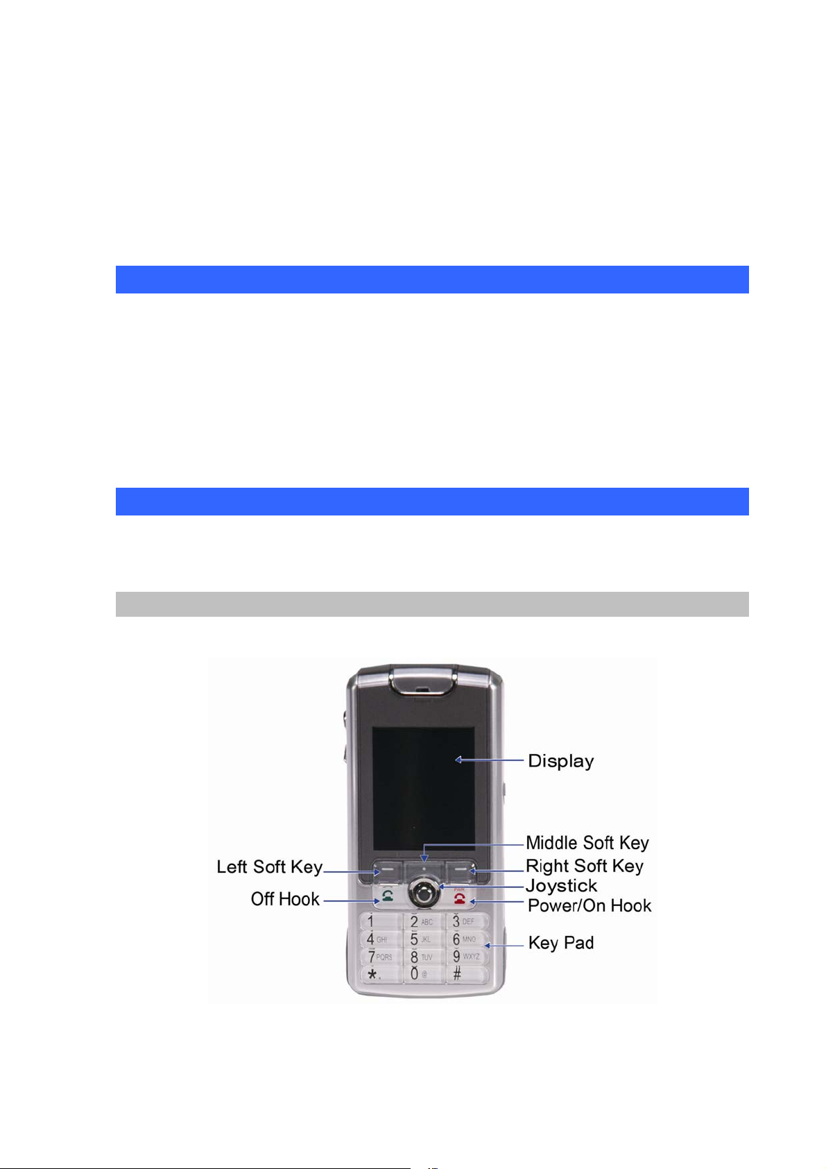
Physical Details
The following figure illustrates the front/rear and side view of IP Phone.
Front view and keypad function:
Figure 1. Front view of VIP-192
9
Page 10
Keypad Definition
Text Mode Text Mode
Key
Normal (ABC)
Numeric
Key Normal (ABC) Numeric (123)
(123)
7 P Q R S p q
1 [Space] 1
2 A B C a b c 2 8 T U V t u v 8
r s
7
9 W X Y Z w x
3 D E F d e f 3
y z
9
0 @ ! _ - ( )
4 G H I g h i 4
5 J K L j k l 5
6 M N O m n o 6
Table 1. Keypad definition description of VIP-192
% & + / $ , :
. * + . * +
# #
0
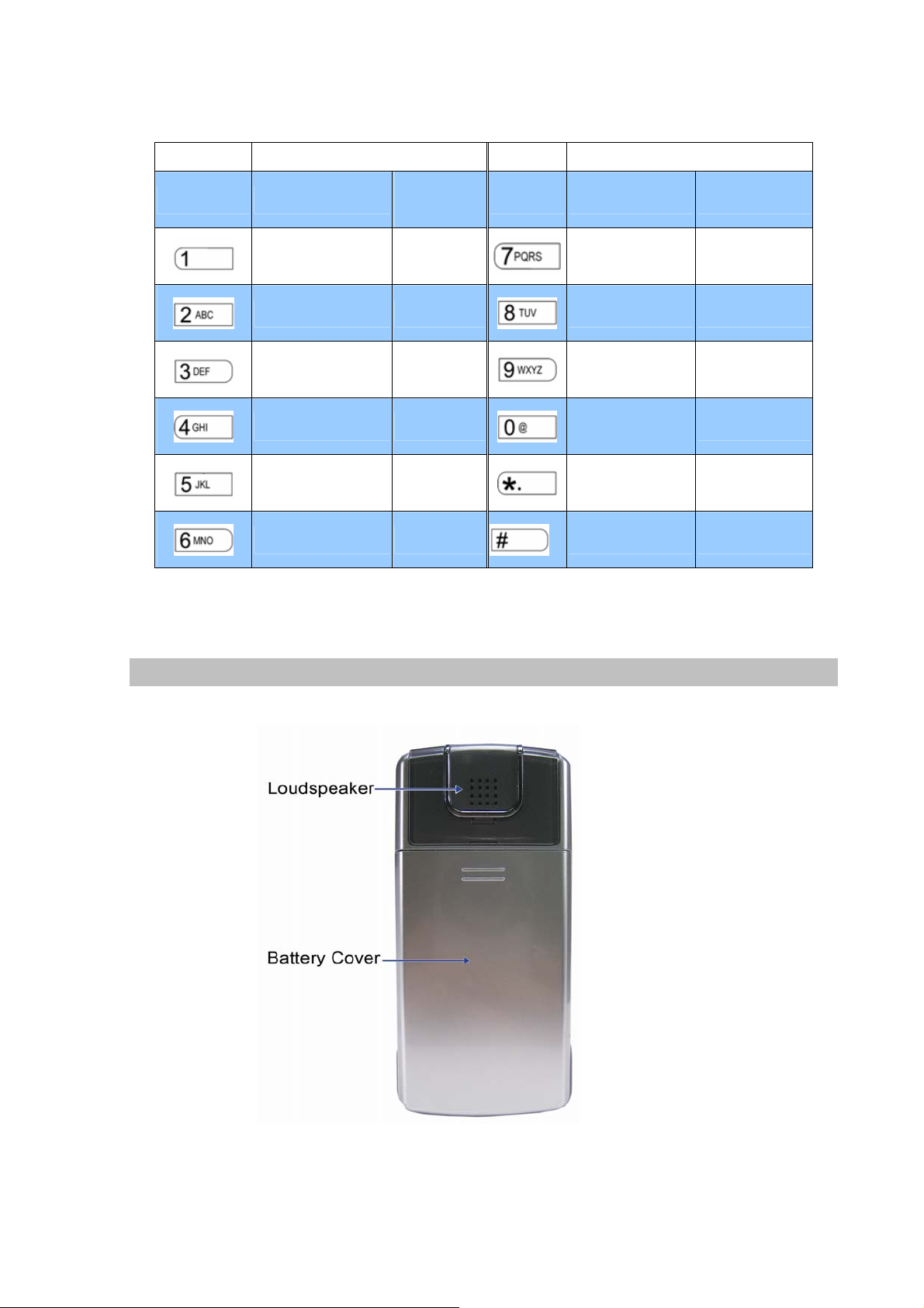
Rear view and parts definition:
Figure 2. Rear view of VIP-192
10
Page 11
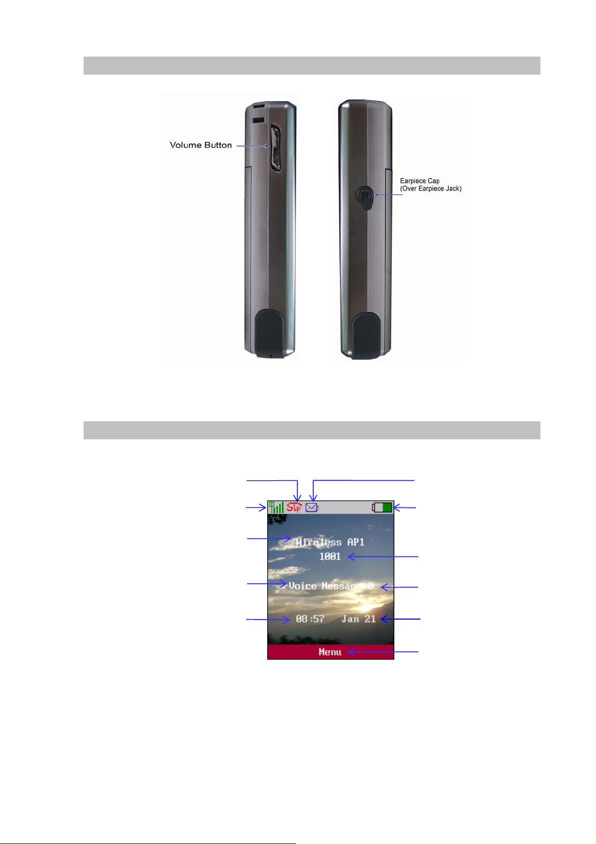
Side view and parts definition:
Normal Mode / Main Screen:
WiFi Signal Strength
SIP Status
SSID of linking AP
Voice Message Indicator
Time
Figure 3. Side view of VIP-192
SMS Indicator
Battery Status
Registered SIP number
Wallpaper of standby mode
Date
Menu
Figure 4. Main screen
11
Page 12
Chapter 2
Preparations & Installation
Physical Installation Requirement
This chapter illustrates basic installation of Wi-Fi Phone
Administration Interface
PLANET Wi-Fi Phone has provides keypad and web methods for machine management and
administration.
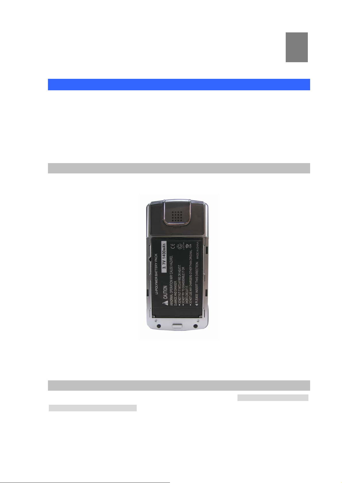
Installing the Battery:
To remove the battery cover and insert the battery then put the cover back to the Wi-Fi phone.
2
Figure 5. Mounted the battery view
Charging the Battery
The battery must be fitted in the phone before you connect to the adapter. Start to charge the phone
at least 8 hours in first time use. About 4 ~ 5 hours charging after the first time usage.
12
Page 13
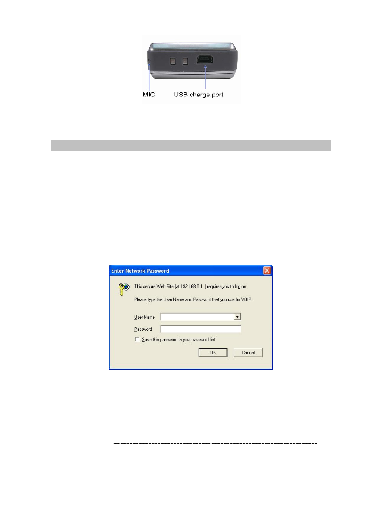
Figure 6. Bottom view
Web Configuration access
To start Wi-Fi Phone web configuration, you must have one of these web browsers installed on
computer for management
• Microsoft Internet Explorer 6.0 or higher with Java support
Default WLAN interface IP address of Wi-Fi Phone is 192.168.0.1. You may now open your web
browser, and insert 192.168.0.1 in the address bar of your web browser to logon Wi-Fi Phone web
configuration page.
Wi-Fi Phone will prompt for logon username/password, please enter: root / 1234 to continue machine
administration.
ÍNote
Figure 7. Prompt screen of VIP-192
Please locate your PC in the same network segment
(192.168.0.x) of Wi-Fi Phone. If you’re not familiar with
TCP/IP, please refer to related chapter on user’s manual
CD or consult your network administrator for proper network
configurations.
13
Page 14
Chapter 3
3
Menu Structure & Network Settings
Menu Structure
To enter the “Main Menu”, press the <middle button of soft key> or middle button of joystick in the
wallpaper screen.
Figure 8. Main menu
Phone Book
1. New
2. Browse
3. Delete All
4. Memory Status
Entertainment
1. JAVA Download
Phone Settings
Messaging
1. Voicemail
2. SMS
3. E-mail
Network Settings
1. Network Config
2. Wireless
3. SIP
4. NAT
Information
Call Log
1. Missed
2. Dialed
3. Received
4. Delete
Application
1. Calendar
2. Calculator
Call Function
1. Date & Time
2. Language
3. Backlight Level
4. Ring Volume
5. Voice Volume
Page 1
1. IP Address
2. Subnet Mask
3. Default Gateway
1. Do Not Disturb
2. Call Waiting
3. Anonymous Call
4. Anonymous Reject
5. Call Forward
14
Page 15
6. Alert Type
Page 2
7. Wallpaper Management
8. Ringtone Management
9. Holdtone Management
10. Power Save
11. Change Password
12. Speed Dial
1. AP
2. MAX Rate
3. Channel
Page 3
1. SIP ID
2. MAC Address
3. Version
Table 2. Menu structure
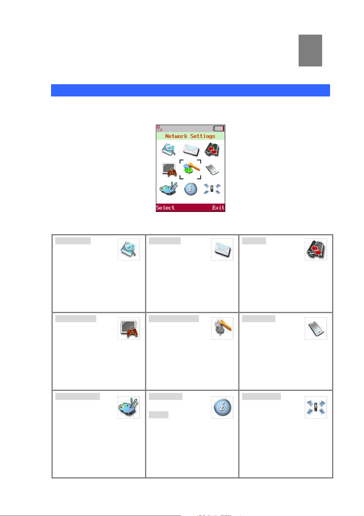
Network Settings
To enter the Network Setting, use joystick to locate [Network Settings] icon and press the <left soft
key> Select to enter this sub-menu. The sub-menu provides four items: [Network Config],
[Wireless], [SIP], and [NAT ].
Figure 9. Main menu
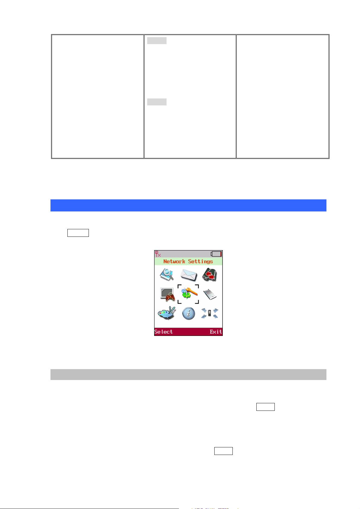
Network Config
The system supports DHCP that allow assign both IP addresses automatically and manually under
static IP. Please ensure the network environment range is set properly.
Move the highlight bar to [Network Config] and press the<left soft key> Select to enter the page.
This page provides two items that are [IP] & [DNS Setting].
IP Settings
Move the highlight bar to [IP]and press the <left soft key> Select to enter this IP Setting menu. User
can choose either [DHCP]or [Static IP]. User is able to setup manually by using joystick keys to
15
Page 16
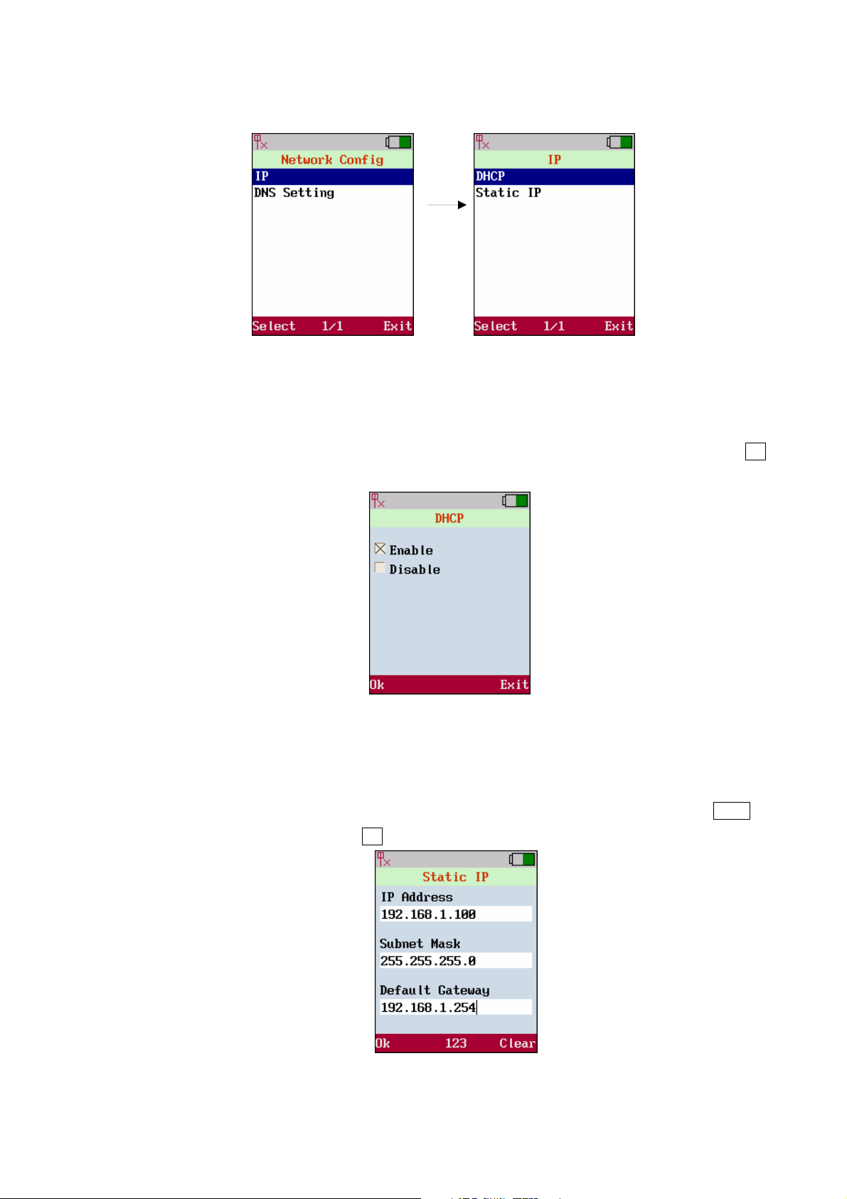
enter the column as user needs and insert the necessary data.
Figure 10. IP settings
1. DHCP
Use joystick to select either [Enable] or [Disable], select [Enable] the IP will be obtained
automatically or user should setup IP manually by choosing[Disable]. Press <left soft key> Ok
to save the configuration.
Figure 11. DHCP settings
2. Static IP
Get the information from the service provider before user enters data into the filed. Use joystick to
locate the column of filed where user is going to input the data; also use <right soft key> Clear to
clear data. Press <left soft key> Ok to save the configuration.
Figure 12. Static IP settings
16
Page 17
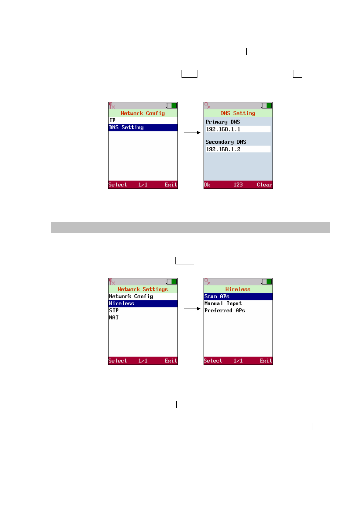
DNS Settings
Move the highlight bar to [DNS Setting] and press the <left soft key> Select to enter the[IP]menu.
There are [Primary DNS] and [Secondary DNS]. Use joystick to locate the column of filed where
user wish to input the data; use <right soft key> Clear to clear data. Press <left soft key> Ok to save
the configuration.
Figure 13. DNS settings
Wireless
Before user uses the WLAN phone, user needs to setup the AP which will be associated. In the
wireless setup, user is able to modify the data of [ESSID] and [Security] by moving the highlight
bar to[Wireless]. Press the <left soft key> Select to enter Wireless Settings.
Figure 14. Wireless settings
Scan APs
To Scan APs, press the <left soft key> Select to scan available APs. It will list all the ESSIDs of
available APs or show “No AP found” message in case there is no AP detected by the system. Move
the highlight bar to the AP. User wish to link any dedicate AP and press the <left soft key> Select. It will
pops-up a small window that lists [Information],[Set as Preferred AP]and[Connect Now].
17
Page 18
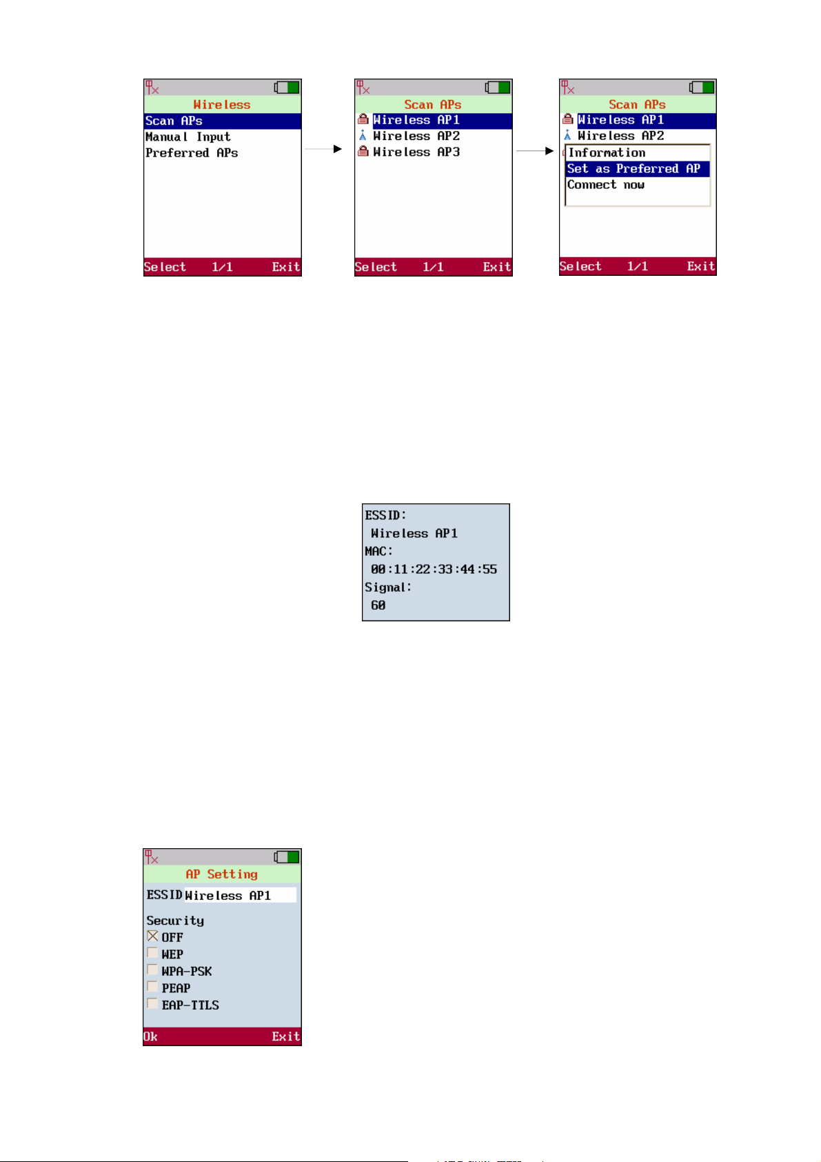
Figure 15. Scan APs
1. Information
List AP information of [ESSID], [MAC] and [Signal].
- [ESSID]: It is the unique identification of the AP in the WLAN system and constructed by
2~32 characters.
- [MAC]: The MAC address of the AP.
- [Signal]: The strength of the signal (1~100; “100” is the maximum).
Figure 16. Information
2. Set as Preferred AP
Save the profile of the AP into Preferred APs, user may have several preferred APs. Repeat the
steps of Scan APs to add more preferred APs.
3. Connect now
Associate with the AP immediately. Once user selects the[Set as Preferred AP], it will show the
AP Settings menu which contains two main item[ESSID]and[Security].
♦ ESSID: The unique ID of the AP in the WLAN system.
♦ Security: It supports five types of security: OFF, WEP,
WPA-PSK, PEAP and EAP-TTLS.
18
Page 19
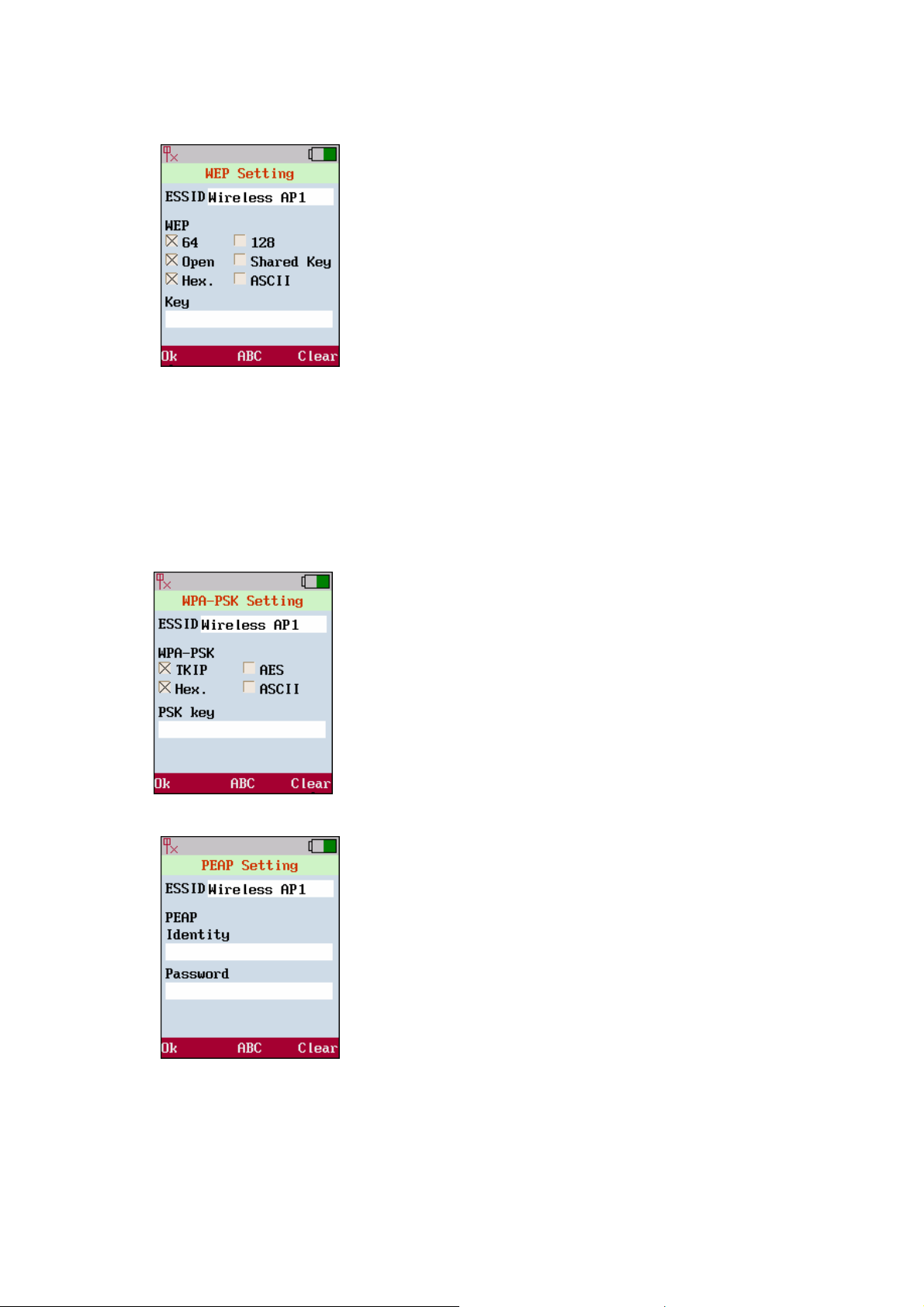
The detail of the five types of security is as follows: (“OFF” Æ no security is required)
WEP (Wired Equivalent Privacy)
♦ 64-bit / 128-bit: Two levels of WEP key, which can be 64 bits or
128 bits.
♦ Open / Shared Key:
- Open: WEP key is used for encryption only.
- Shared Key: WEP key is used for both authentication and
encryption.
♦ Hex / ASCII:
- Hex: It allows to input the digits of 0~9 and A~F, and the
length of the WEP key must be 10 digits for 64-bit or 26
digits for 128-bit.
- ASCII: It allows to input the characters in the ASCII system,
and the length must be 5 characters for 64-bit or 13
characters for 128-bit.
WPA-PSK (Pre Share Key)
♦ TKIP / AES: Two types of encryption protocol; the upgrade for
WEP.
- TKIP: Temporal Key Integrity Protocol.
- AES: Advanced Encryption Standard.
♦ Hex / ASCII:
- Hex: It allows to input total 64 digits of 0~9 and A~F.
- ASCII: It allows to input 8~63 characters in the ASCII system.
PEAP (Protected EAP)
♦ Identity: The ID for authentication and allow 31 characters.
♦ Password: The password for authentication and allow 31
characters.
19
Page 20
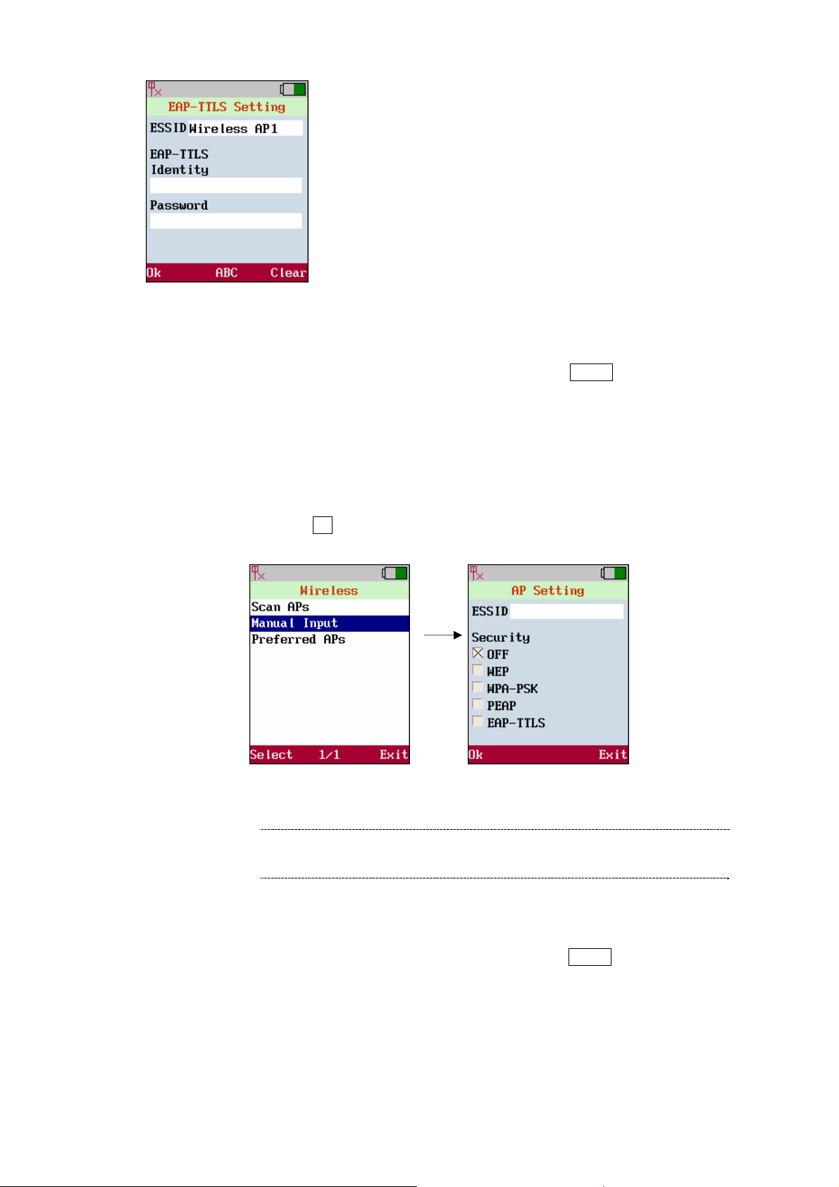
EAP-TTLS
♦ Identity: The ID for authentication and allow 31 characters.
♦ Password: The password for authentication and allow 31
characters.
Manual Input
Move the highlight bar to[Manual Input]and press the <left soft key> Select to setup AP manually.
1. Enter[ESSID]of the AP user wishes to link.( ESSID: Shows the name of linking AP and allows
total 31 characters)
2. Move the cursor to setup[Security]length and type of authentication that user wishes to link.
(Use navigation keys to turn on/off or set up this function.)
3. Press the <left soft key> Ok to store the settings.
Figure 17. Manual input
ÍNote
Wi-Fi Phone will automatically search for the available AP
when it boots up at the first time.
Preferred APs
Move the highlight bar to[Preferred APs]and press the <left soft key> Select to select available APs.
20
Page 21
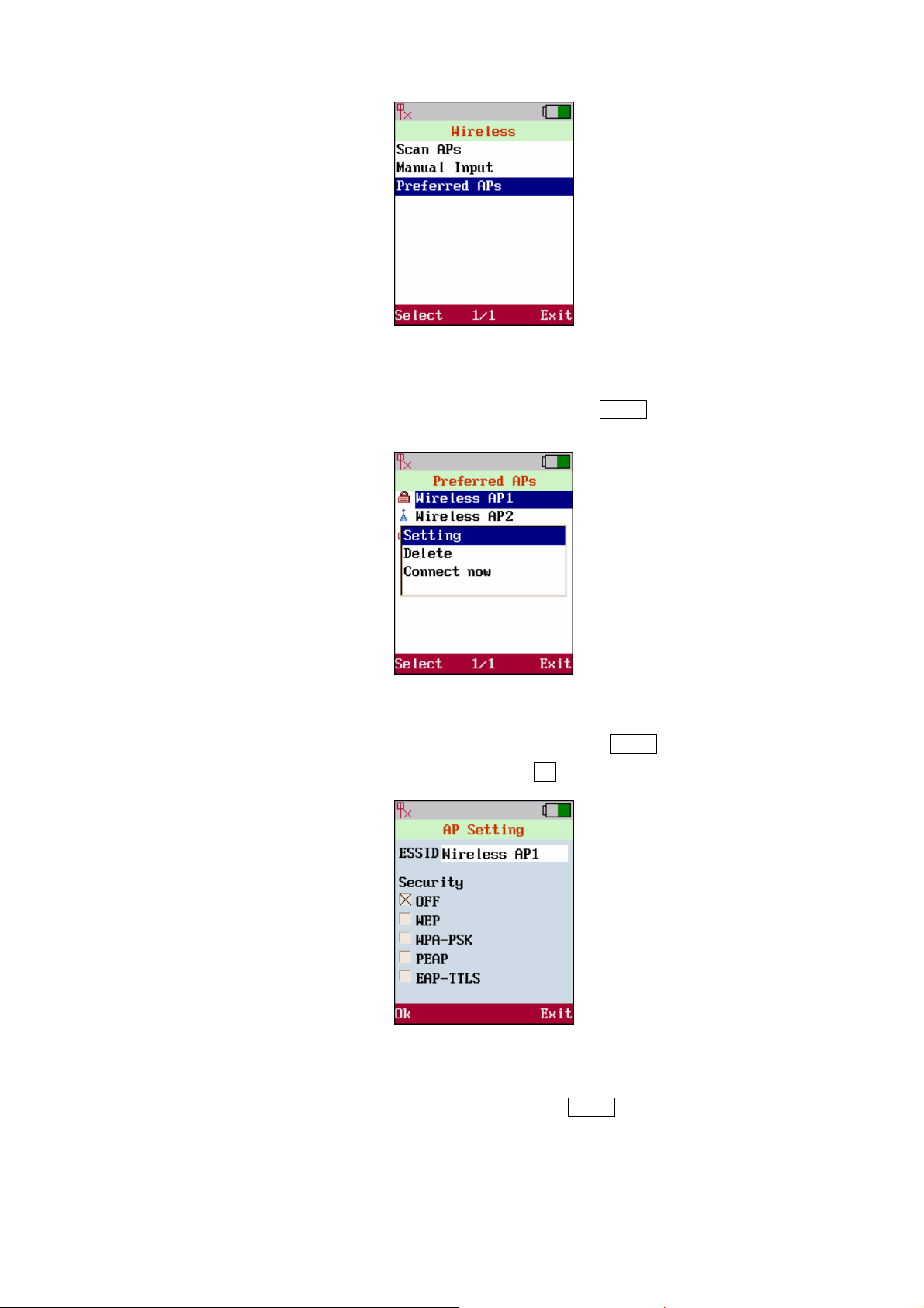
Figure 18. Preferred APs
Move the highlight bar to the AP to link and press the <left soft key> Select. It will pops-up a small
window that lists[Setting],[Delete]and[Connect now]
Figure 19. Setting
Move the highlight bar to[AP Setting]and press the <left soft key> Select to setup[ESSID],
[Security]of this preferred AP. Press the <left soft key> Ok to store the settings.
Figure 20. AP Setting
Move the highlight bar to [Delete]and press the <left soft key> Select to delete AP from preferred APs
list. [Conne ct now] function means the AP which is selected and will start to be used for further
access. The system will automatically scan for the available AP when it boots up at the first time.
21
Page 22
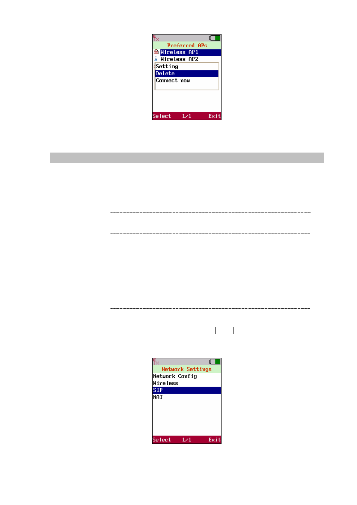
Figure 21. Delete
SIP Setting
Session Initiation Protocol (SIP) is the most popular Voice over IP standard. It enables two or more
people to make phone calls, share multimedia and make multimedia conference over the internet.
Please have an administrator setup these settings or obtain this information from the SIP service
provider.
ÍNote
SIP setting define the SIP registrar address, SIP account and related SIP parameter. The SIP account
information is required before user setup.
ÍNote
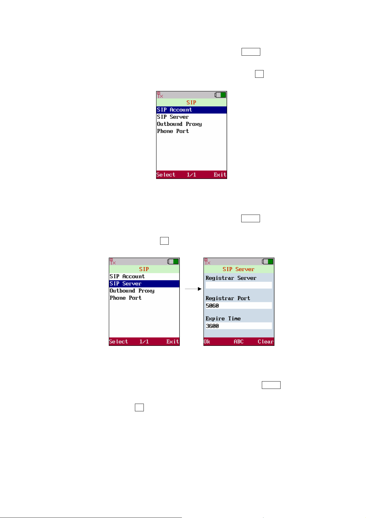
Move the highlight bar to[SIP]and press the <left soft key> Select to enter SIP Settings. This page
provides four items: [SIP Account], [SIP Server], [Outbound Proxy]and[Phone Port].
Please have an administrator setup these settings or obtain
this information from the SIP service provider.
User could contact the service provider (eg carrier or ITSP)
to get the information.
Figure 22. SIP setting
22
Page 23
SIP Account
Move the highlight bar to[SIP Account]and press the <left soft key> Select to enter this SIP Account
menu. Move cursor into the field of [Display name], [User Name], [Authentication ID]and
[Authentication Password]for inputting data. Press the< left soft key> Ok to store the settings.
Figure 23. SIP account
SIP Server
Move the highlight bar to[SIP Server]and press the <left soft key> Select to enter this SIP Server
menu. Move cursor into the field of[Registrar Server], [Registrar Port]and[Expire Time], for
inputting data. Press the <left soft key> Ok to store the settings
Figure 24. SIP server
utbound Proxy
O
Move the highlight bar to
Outbound Proxy menu. Move cursor into the field of [Proxy Server]and [Proxy Port], for inpu
[Outbound Proxy]and press the <left soft key> Select to enter this
tting
data. Press the <left soft key> Ok to store the settings.
23
Page 24

Figure 25. Outbound proxy
Phone Port
Move the highlight bar to[Phone Port]and press the<left soft key> Select to enter Phone Port menu.
Move cursor into the field of[Phone Port]for inputting data. Press the <left soft key> Ok to store the
settings.
Figure 26. Phone port
NAT Setting
Enable[STUN] or[UPnP] to activate the NAT traversal function if this device is behind NAT
mechanism. Ensure user NAT router support UPnP as well. Refer to the operation manual of user
router for any further information.
Figure 27. NAT setting
24
Page 25

STUN & UPnP
Move the highlight bar to [NAT] and press the <left soft key> Select to enter NAT. Sub menu
provides four items;[STUN & UPnP], [STUN Server], [Manual Config]and [NAT Keep Alive
Time].
Figure 28. STUN & UPnP
Phone Port
Move the highlight bar to [STUN & UPnP]and press the <left soft key> Select to enter this [STUN
& UPnP]setting menu. Move cursor to enable or disable [STUN & UPnP]function. Press the <left soft
key> Ok to store the settings.
Figure 29. STUN & UPnP
STUN Server
Move the highlight bar to [STUN Serv er]and press the <left soft key> Select to enter this STUN
Server menu. Move cursor into the field of [STUN Server] for entering STUN server IP address
when enable[STUN server]. Please press the <left soft key> Ok to store the settings.
25
Page 26

Figure 30. STUN server
Manual Config
Setup the external IP address manually. It has to be complied with the settings of virtual server of the
NAT devices, if phone enables the configuration manually. Move the highlight bar to[Manual Config]
and press the <left soft key> Select to enter this Manual Config menu. This page provides three items;
[User Define],[External IP add]and[External Port].
Figure 31. Manual config
1. User Define
Move the highlight bar to [User Defin e]and press the <left soft key> Select to enter this User
Define menu. Move cursor to [Enable]or [Disable]User Define function. Press the <left soft
key> Ok to store the settings.
Figure 32. User defined
26
Page 27
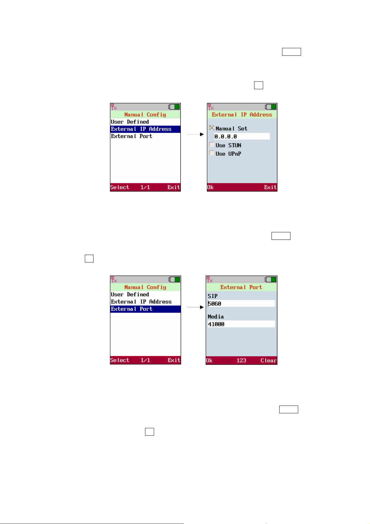
2. External IP Address
Move the highlight bar to [External IP address] and press the left soft key Select to enter this
External IP menu. Enter External IP. 1. Manual set. 2. Use Stun server to get External IP
address. 3. Use UPnP to get External IP address. Move cursor to setup the field of[Manual
Set]or[Use STUN]or[Use UPnP]. Press the <left soft key> Ok to store the settings.
Figure 33. External IP address
3. External Port
Move the highlight bar to[External Port] and press the <left soft key> Select to enter this
External Port Menu. Move cursor to setup the field of [SIP]and [Media]. Press the <left soft
key> Ok to store the settings.
Figure 34. External port
NAT Keep Alive Time
Move the highlight bar to [NAT KeepAlive Time] and press the <left soft key> Select to enter this
NA T KeepAliv e Time menu. Move cursor to setup the field of [Always Send] and [KeepAlive
Time]. Press the <left soft key> Ok to store the settings.
27
Page 28

Figure 35. NAT keep alive time
28
Page 29

Chapter 4
Phone book
4
Phone Book
Use the Phonebook menu to[store],[browse],[edit]and[delete]a person’s name, Phone number
and e-mail address. Enter the main menu and use joystick to locate[Phonebook]icon. Press the <left
soft key> Select to enter Sub-Menu.
Figure 36. Phonebook
Create a New Contact
Move the highlight bar to[New] and press the left soft key Select to enter this Phonebook menu.
Move cursor into the field of [Name], [Phone Number] and [E-mail] for inputting data. Also
user can input the alphabet by pressing <middle soft key> to switch. Press the <left soft key> Ok to
store the settings.
Figure 37. New contact setting
29
Page 30

For each contact user can insert:
Item Number of digits
Name 31
Phone Number 63
Email 63
Table 3. Number of digits limit
Browse
Move the highlight bar to[Browse]and press the <left soft key> Select to enter the Browse menu.
Figure 38. Browse setting
The highlight bar will locate the record that user would like to find. Move the highlight bar to [name]
and press the <left soft key> Select to View or Delete the contacts.
Figure 39. Select contact
30
Page 31

User may save this new data after editing.
Figure 40. Save setting
User may delete the editing data; select Delete to erase this contact.
Delete All
Move the hi
Book.
Figure 41. Delete setting
ghlight bar to[Delete All]and press the <left soft key> Select to all the records in Phone
Figure 42. Delete all setting
31
Page 32

Memory Status
r to[Memory Status]and press the <left soft key> Select to show the memory Move the highlight ba
status. It provides total 200 records in maximum.
Figure 43. Memory Status
32
Page 33

Chapter 5
Messaging
5
Messaging Settings
Messaging menu include the[Voicemail], [SMS], and[E-Mail]. These features provides user to
view, listen, retrieve and input any messages.
Figure 44. Messaging setting
Voicemail
In case caller could not reach the called, caller can leave message in the voice mail server. The voice
mail server will follow the VMWI (Virtual Message Waiting Indication) standard to send the indication
message. When system receives a message it will show the mail icon on the upper status bar.
Voicemail feature enables the system to show the voice message and retrieve the voice from the voice
mail server.
Move the highlight bar to [Voicemail]and press the <left soft key> Select to enter this menu. It will
show the number of voice message that user have. User is able to press the <left soft key> Dial to
access the mailbox.
Figure 45. Voicemail setting
33
Page 34

SMS
System is capable to send short text message to the other system when it is not convenience for user
to communicate by voice. Move the highlight bar to [SMS]and press the <left soft key> Select to enter
this menu. There are four items in this menu, [New],[Inbox],[Archive ],[Delete]and [Memory
Status].
Figure 46. SMS setting
New
In order to create new message, user has to select[Content]to edit the content of message. It allows
500 letters in maximum to be entered in one message. (A symbol table will be present by pressing *
and # keys while editing the message). Then, select[Send]and enter the phone number to send this
message by pressing <left soft key> Ok.
Figure 47. New contact setting
34
Page 35

Inbox
It shows the received messages. Move the highlight bar to the selected record and press the <left soft
key> Select to popup a new screen with items[View], [Reply], [Delete]and [Information].
Figure 48. Inbox setting
1. View: View the content of the selected message.
2. Reply: Reply a new message to the sender.
3. Delete: Erase the message.
4. Information: It includes the ID and phone number of the sender, and the time at which the
message is arrived.
Archive
When a message is sent and user presses the <right soft key> Exit to exit, it asks the user whether
he/she want to save the message. User can press the <left soft key> Ok to save the message at this
moment.
Figure 49. Save message
Move the highlight bar to the selected message and press the <left soft key> Select to popup a new
screen with items[View]and [Delete]. The selected message can be resent to a new destination with
or without modification after the message is viewed.
35
Page 36

Figure 50. View messages
Delete
Move the highlight bar to[Delete]and press the <left soft key> Select. It will popup a new screen with
the items[Delete All], [Inbox]and [Archive]to select what will be deleted.
Figure 51. Delete messages
Memory Status
Move the highlight bar to[Memory Status]and press the <left soft key> Select to show the status of
memory space. User is able to select [Inbox]or[Archive]. Both Inbox and Archive provide 60
records in maximum.
Figure 52. SMS memory status
36
Page 37

The system can send and receive E-mail from most popular mail server such as [POP3]and[SMTP].
Sending and Receiving emails are fully requires to inserts mail account.
Figure 53. E-Mail setting
Account
This page shows or inputs display name and mail address which will show[Sender Address]by the
receiver mail.
Field Description
Display Name
Mail Address
Display name which shown as the sender’s name.
Mail Address which shown as the sender’s mail address.
Table 4. Account setting description
Figure 54. Account setting
37
Page 38

POP3 Setting
The Post Office Protocol - Version 3 (POP3) is intended to permit a workstation to dynamically access
a mail drop on a server.
Field Description
POP3 Server Address
POP3 User ID
POP3 password
POP3 Port
SMTP Setting
The address of POP3 server
User name for register to the POP3 Server
Password for register to the POP3 Server
Port no. Use for POP3 protocol
Table 5. POP3 setting description
Figure 55. POP3 setting
SMTP (Simple Mail Transfer Protocol) is a relatively simple, text-based protocol, where one or more
recipients of a message are specified (and in most cases verified to exist) and then the message text is
transferred.
Figure 56. SMTP setting
38
Page 39

Advance
Field Description
APOP
Reserve Mail
Reply Address
Signature
APOP (Authenticated Post Office Pro tocol) it is similar to the POP
protocol
while being transmitted over the network. Using POP mail, when user
authenticates user’s username
user password is sent over the network
It will reserve the mail in the serve
Reply mail with address
It will automatically add the signature to the mail when initial a new
mail or reply a mail.
except that APOP enables user password to be encrypted
and password in user e-mail client,
in plain text.
Table 6. Advance setting description
Figure 57. Advance setting
39
Page 40

Chapter 6
Call Log
From the Call Log menu user can view all the call history in this phone.
Figure 58. Call Log setting
It is grouped into[Missed],[Dialed],[Received]and[Delete]
Call Log
6
Figure 59. Call Log selections
40
Page 41

Chapter 7
Application
7
Application
The system supports the most continence tool, calendar and calculator. Use the calendar to view the
date. Enter the main menu and use joystick to locate[Application]icon. Press the <left soft key>
Select to enter this sub-menu.
Figure 60. Application setting
Calendar
Move the highlight bar to[Calendar]and press the <left soft key> Select to enter this menu. Click ◄
<Left>/ ►<Right> of Navigation Key to view pervious or the following month, also user can create a
personal memo by selecting the date.
Figure 61. Calendar setting
41
Page 42

Memo
Move highlight to[Memo]and use left soft key to press <left Soft key> Select that will show three
functions [New], [View] and[Delete].
Figure 62. Memo setting
Select Date
The date user wants to create memo.
Figure 63. Select date setting
Delete All Memos
In order to delete any date of memo that user had created, move highlight to[Delete All Memo].
Figure 64. Delete all memos setting
42
Page 43

Memory Status
Show the status of memory space.
Figure 65. Memory status setting
Calculator
Move the highlight bar to[Calculator]and press the <left soft key> Select to enter this menu. Please
use the joystick as screen shows to calculate the number user needs.
Figure 66. Calculator setting
43
Page 44

Chapter 8
Phone Settings
Phone Settings
Phone Settings provides all standard phone functionalities settings.
Figure 67. Phone settings
Time & Date
Move the highlight bar to[Time & Date]and press the <left soft key> Select to enter this menu. Enter
8
[NTP] (Network Time Protocol) server IP to have accurate time or enter by manually.
Figure 68. Time & Date setting
Language
Move the highlight bar to[Language]and press the <left soft key> Select to user suitable languages.
Support Languages: English, Japanese, Traditional Chinese, Simplified Chinese, Korean and
Castellano.
44
Page 45

Figure 69. Language setting
Backlight Level
Move the highlight bar to [Backlight Level]and press the <left soft key> Select to enter this menu.
Use joystick ◄ <Left>/ ►<Right> to adjust the backlight level and press OK to save the setting.
Figure 70. Backlight Level setting
Ring Volume
Move the highlight bar to[Ring Volume]and press the <left soft key> Select to enter this menu. Use
joystick ◄ <Left>/ ►<Right> to adjust the sound level then press OK to save the setting.
Figure 71. Ring volume setting
45
Page 46

Voice Volume
Move the highlight bar to[Voice Volume]and press the left soft key Select to enter this menu. Use
joystick ◄ <Left>/ ►<Right> to adjust the sound level then press OK to save the setting.
Figure 72. Voice volume setting
Alert Type
The system can setup the incoming call indication types. User is available to set as Vibrate or Ring
Types.
Figure 73. Alert type setting
Wallpaper Management
The system supports selectable wallpaper while in the standby mode, user can select the preferable
picture as wallpaper and download photo from the network as well. Move the highlight bar to[Image
Management]and press the <left soft key> Select to enter this menu. Chose the image and press <left
Soft key> Select to set as wallpaper.
46
Page 47

Figure 74.Wallpaper management setting
ÍNote
Wallpaper format: BMP,
Wallpaper Size: 176 x 220(16 bits)
Ring tone Management
The system supports a variable ring tones. For the incoming calls, user may chose preferable melody
also providing access download from the network as well. Move the highlight bar to[Ring tone
Management]and press the <left soft key> Select to enter this menu.
Figure 75.Ring tone management setting
Hold tone Management
The system supports various tones for the condition that the phone is on hold. Move the highlight bar to
[Hold tone Management]and press the <left soft key> Select to enter this menu.
47
Page 48

Figure 76.Hold tone management setting
Power save
Move the highlight bar to[Power Save]and press the <left soft key> Select to enter this menu. There
are two items, Normal & Maximum, in the[Power Save]setting. Use joystick to select the item you
want then press OK to save the setting.
“Normal” is the default setting. If user wants to save more power, user can just select the “Maximum”
item to achieve it. Besides, if the “Maximum” is selected, the LCD display will be blacked (turned-off)
and shown the current time during the stand-by status.
Figure 77.Power save setting
Change Password
Move the highlight bar to [Change Password] and press the <left soft key> Select to enter this menu.
Enter the password to inform the new password.
48
Page 49

Figure 78.Change password setting
Speed Dial
The system supports to browse and edit the content of Speed Dial, which provides total 20 records via
the handset. Move the highlight bar to[Speed Dial]and press the <left soft key> Select to enter this
menu. There are two items[Edit]and[Browse]on screen.
Edit
Select [Edit]and press the <left soft key> Select to edit the records. Enter the number of record
(00~19) and the phone number into the blank field.
Browse
Select[Browse]to browse the records.
Figure 80.Browse setting
Figure 79.Edit setting
49
Page 50

Chapter 9
Information
Information
Information will help user to understand the basic input data of the system such as [IP Address],
[Subnet Mask], [Default Gateway], [AP], [Max Rate], [Channel], [SIP ID],
[MAC Address] and [Firmware Version].
Figure 81.Information setting
9
The information shows[IP status],[WLAN Status],[SIP & MAC Status].
Figure 82. Information screen
50
Page 51

Chapter 10
Call Function
10
Call Function
Call function supports four main items such as, [Do not Disturb],[Call Waiting],[Call Forward],
[Anonymous Call]and[Anonymous Rejec t].
Figure 83. Call function screen
Do Not Disturb
[Do not Disturb]feature enables the system to reject all the phone calls from any others. Move the
highlight bar to[Do not Disturb]and press the <left soft key> Select to enter this menu. Use joystick
to select the [Enable]or [Disable] item then press <left Soft key> OK to save the setting.
Figure 84. Do not disturb setting
Call Waiting
[Call Waiting]feature enables the system to notify the user by playing the [Remind Tones]when
someone calls the user while he/she is already on the line.
Move the highlight bar to[Call Waiting]and press the <left soft key> Select to enter this menu. Use
joystick to select the [Enable]or [Disable] item then press <left Soft key> OK to save the setting.
51
Page 52

Figure 85. Call waiting setting
Anonymous Call
Making[Anonymous Call]means that user makes the call without sending the caller name or number.
Move the highlight bar to[Anonymous Call]and press the <left soft key> Select to enter this menu.
This function provides user [hiding caller ID], also user can either enable to hide [Full URI]or
[Display Name].
Figure 86. Anonymous call setting
Anonymous Reject
Move the highlight bar to[Anonymous Reject]and press the <left soft key> Select to enter this menu,
this function provides user to reject the incoming call who hiding caller ID, user can either[Enable] or
[Disable] this function.
52
Page 53

Figure 87. Anonymous reject setting
Call Forward
The [Call forward] feature enables the system forward the incoming call to the specified phone
number to prevent missing call when user are not available to answer the call.
Move the highlight bar to call Forward and press the <left soft key> Select to enter this menu, this
menu provide 3 items to setup, such as[Unconditional],[Busy ]and[No Answer].
Figure 88. Call forward setting
Unconditional
Use joystick to enable or disable this function, if enabled, please enter the Phone Number or IP address.
Please press the <left soft key> Ok to store the settings.
Figure 89. Unconditional setting
Forward on Busy
Use joystick to enable or disable this function
Enable: Enter the phone number or IP address. Press the <left soft key> Ok to store the settings.
53
Page 54

Figure 90. Forward on busy setting
Forward on No Answer
Use joystick to enable or disable this function.
Enable: Enter the phone number or IP address. Press the <left soft key> Ok to store the settings.
Figure 91. Forward on no answer setting
54
Page 55

Chapter 11
Using the web configuration
11
Using the web configuration
The configuration web can be accessed using a web browser.
Accessing Configuration Menu
To start Wi-Fi Phone web configuration, you must have one of these web browsers installed on
computer for management
• Microsoft Internet Explorer 6.0 or higher with Java support
Default WLAN interface IP address of Wi-Fi Phone is 192.168.0.1. You may now open your web
browser, and insert 192.168.0.1 in the address bar of your web browser to logon Wi-Fi Phone web
configuration page.
Wi-Fi Phone will prompt for logon username/password, please enter: root / 1234 to continue machine
administration.
Figure 92. Prompt screen of VIP-192
55
Page 56

Web Login Setting
Figure 93. Main page
Field Description
User Name
Password
NTP Server IP
Time Zone
TFTP Server
FTP Client
Username for login the web configuration
Password for login the web configuration
Network Time Protocol (NTP) is a protocol used to help match user
system clock with an accurate time source (eg atomic clock, time
server). It is good practice to have all user networked computers
synchronized with one server.
Select user time zone. If there is daylight saving in user area, click
the check box.
Enable or Disable TFTP server to allow uploading firmware from a
computer to IP phone.
Enable or disable IP phone to download files from FTP server and
update the firmware automatically.
Table 7. Main page description
Restore Factory Setting
Click on “Management”, Select “Restore Factory Setting” and the above screen will display on the
screen.
56
Page 57

Figure 94. Restore default setting
Field Description
Restore Factory Setting
Restores all the settings back to factory default
settings.
Table 8. Restore factory description
Firmware update
FTP server, login ID, login password and firmware filename are preset when user purchases the phone.
These are required to download and update the firmware.
Figure 95. Firmware updates setting
Field Description
FTP Server
Login ID
Login Password
Firmware Filename
FTP Server address
Login ID provided by user’s supplier.
Login password provided by user’s supplier.
Updated firmware filename. Do not change the file
name unless specified by user’s supplier.
Table 9. Firmware update description
Network Setting-DHCP
Select DHCP if user has cable Internet.
57
Page 58

Figure 96. Network setting-DHCP
Field Description
Dynamic Host Configuration Protocol (DHCP) Server
DHCP Server
DNS Server 1~2
Table 10. Network setting-DHCP description
address. This IP address information is obtained
automatically from user ISP.
DNS address provided by user’s ISP.
Network Setting-Static IP
Choose Static IP network setting if all Wide Area Network IP is provided to user by ISP.
Figure 97. Network setting-Static IP
Field Description
IP Address
Router IP
Subnet Mask
DNS Server 1~2
Table 11. Network setting-Static IP description
IP address assigned to user by user’s ISP.
Router IP addresses.
Subnet Mask address.
DNS server address provided by user’s ISP.
58
Page 59

ÍNote
QoS Setting
RESTART the system for new settings to take effect after
user modifies the IP address.
Figure 98. QoS setting
Field Description
Voice TOS
SIP TOS
Set the type of service for RTP stream.
Set the type of service for SIP signaling.
Table 12. QoS setting description
SIP Setting
Session Initiation Protocol (SIP) is the most popular Voice over IP standard. It enables two or more
people to make phone calls, share multimedia and make multimedia conference over the Internet.
Please have an administrator to setup these settings or obtain this information from user SIP service
provider.
Figure 99. SIP setting
59
Page 60

Field Description
SIP Phone Port Number
SIP phone port number
Registrar Server Domain
Registrar server domain name or IP address.
Name/IP Address
Registrar Server Port Number
Registrar server port number
The time after which the registration on SIP
Registrar expires. The phone must send SIP
Authentication Expire Time
REGISTER to keep the registration at half of the
setting time.
Outbound Proxy Domain
Outbound proxy domain name or IP address.
Name/IP Address
Outbound Proxy Port Number
Outbound proxy port number.
Table 13. SIP setting description
Figure 100. Message server setting
Field Description
MWI Message Server Domain
Message server domain name or IP address.
Name/IP Address
MWI Message Server Port
Message server port number.
Number
The time after which the subscription expires. It is
MWI Message Subscribe
included in SIP SUBSCRIBE and is used to
Expire Time
negotiate with Message server.
Voice Message Account
Voice message account name
Table 14. Message server description
60
Page 61

Figure 101. Other setting
Field Description
The time interval in which the phone periodically refresh
Session Timer
Media Port
PRAck
Session Refresher
Session Timer Method
UDP/TCP
SIP sessions by sending repeated INVITE requests. These
INVITE requests allow the user agent or proxies to
determine the status of the SIP session.
Real-time Transport Protocol port number. Provides
end-to-end transfer of data with real-time audio.
PRAck ensures that media information is exchanged and
that network checks before connecting the call. Select
Enable for a more reliable connection.
Select None to disable SIP session timer support.
Select UAC to initiate SIP request.
Select UAS to receive SIP request and then return a
response.
Select SIP request method. Default method is Invite.
Select SIP signal transmission method. Default method is
UDP.
When “Set messages via Outbound Proxy” is enabled, all
Register with Proxy
the SIP requests including Register will be sent through
Outbound Proxy.
Table 15. Other setting description
SIP Account Settings
User may have up to 4 accounts. i.e., the IP phone can receive up to four different phone numbers.
61
Page 62

Figure 102. SIP account setting
Field Description
When user dials a number, the default account is
Default Account
Account Active
Display Name
SIP User Name
Authentication User Name
Authentication Password
Register Status
NAT Traversal Settings
used to dial. User Name of default account is
displayed on the receiver’s IP phone.
Enable or disable this account.
Display name on the IP phone.
SIP user name
Username for authentication that is required by SIP
Registrar.
Password For authentication that is required by SIP
Registrar.
Display if the current phone is registered or
unregistered with SIP server.
Table 16. SIP account description
Figure 103. STUN server setting
Field Description
STUN
Simple Traversal of User Datagram Protocol (STUN)
through Network Address Translators is a protocol that
62
Page 63

allows applications to determine the types of NATs and
firewalls are in between them and the internet. STUN also
provides the ability for applications to determine the public
IP addresses allocated to them by the NAT.
STUN Domain Name/IP
Address
Enter STUN domain name or IP address if STUN is
enabled.
Table 17. STUN server description
Figure 104. Manual config external IP/port setting
Field Description
User Defined External
IP/Port
Enable or disable the settings for configuring the user
defined external IP address and port number.
Setup the external IP address manually.
External IP Address
Use Stun server to get external IP address.
Use UPnP to get external IP address.
External SIP Port
External Media Port
Setup external SIP port
Setup external Media port
Table 18. Manual config external IP/port description
Figure 105. UPnP setting
Field Description
Enable or disable universal plug and play. Some NAT supports
UPnP
UPnP so STUN is not required and must be disabled.
Table 19. UPnP setting description
63
Page 64

Figure 106. NAT keepalive time setting
Field Description
Always send keep
alive packet
Keep Alive time
Voice Setting
Enable or disable to keep the channel which is created for
SIP signaling alive.
The time interval that the IP phone always sends the
keepalive packet in order to ensure NAT works properly.
Table 20. NAT keepalive time description
Field Description
Codec
RTP Packet Length
VAD
DTMF Method
Figure 107. Voice setting
Voice Compression Algorithm priority settings. Select from the
most used codec to the least used codec.
The payload size for each RTP packet.
Support VAD for silence suppression. When Enable is selected, it
also supports SID frame for CNG.
Select the method to generate DTMF. Out Band DTMF is based
64
Page 65

on RFC2833.
Payload Type
Phone Setting
Setting the payload type for the Out Band DTMF (Default is 101).
Table 21. Voice setting description
Field Description
Tone Setting
Ringer Type
Hold Tone
Do Not Disturb
Call Waiting
Anonymous Call
Select the tone for particular country
Select the type of ring (1 ~ 15).
Select the type of hold tone (1 ~ 15).
Reject all incoming calls.
Enable or disable call waiting.
1. If DISABLE is selected, full URI and name are sent to the
2. When Full URI is selected, it uses “Anonymous” as its display
3. When Display Name is selected, only display name is replaced
Figure 108. Phone setting
receiver’s phone when the user makes a phone call. The URI
and name of the caller are displayed on the receiver’s phone.
name and URI when the user makes a phone call. It may
display “Anonymous” or nothing on the receiver’s phone.
by “Anonymous” when the user makes a phone call. It may
Anonymous Call
Reject
display “Anonymous” or nothing on the receiver’s phone.
Select Enable to reject anonymous calls.
65
Page 66

1. Click No Answer to enable call forward to another number when
no one answers the phone after 180s (default). The timer can
be changed from 0-600s. Refer to section 6.19 to change the
timer.
Call Forward
2. Click Busy to enable call forward to another number when user
is busy on the phone.
3. Click Unconditional to transfer all incoming calls to another
number.
Enter the call forward number on the text box.
Table 22. Phone setting description
Figure 109. Time setting
Field Description
NTP Recycle
Originating Not
Accept
Incoming No Ans wer
NTP recycle time.
The time interval that the caller’s phone waits to establish a call. If
the receiver fails to answer the phone during this time interval,
the caller’s phone will automatically disconnect.
The time interval that the receiver’s phone will ring. If the receiver
fails to answer the phone during this time interval, the phone will
automatically disconnect.
Table 23. Time setting description
Call Tracing Log
Call Tracing Log keeps a record of all the phone activities. This log is used by our engineers to
troubleshoot hardware problems.
66
Page 67

Figure 110. Call tracing log
Phone Book
Phonebook menu allows the user to add, modify and delete phone numbers. To add, type in the name
and number then click NEW to add. To modify/delete, select the name from the list and click
modify/delete.
Figure 111. Phone book setting
Field Description
Name
Number
Email
Name that you would like to add.
Phone number that corresponds to the name.
Email address that corresponds to the name.
Table 24. Phone book description
67
Page 68

Speed Dial
Speed dial numbers can be accessed from the phone. User can dial *00~*19 then press dial key to
perform speed dial.
Figure 112. Speed dial setting
Field Description
Speed dials phone number. 0x is the speed dial
Number 00 ~ 19
number.
Table 25. Speed dial description
Tools
On tools, system user may use the Web interface to export and import phone book contact list and
system settings.
Figure 113. Tools screen
68
Page 69

Restart System
Click Restart to update all the modifications and reboot the system.
Figure 114. Restart system screen
69
Page 70

Appendix A
Voice Communications
The chapter shows you the concept and command to help you configure your Wi-Fi Phone through
sample configuration. And provide instruction to make calls to desired destination in Wi-Fi Phone. In
this section, we’ll lead you step by step to establish your first voice communication via keypad
operations.
Peer To Peer (P2P) mode
Assuming there are two VIP-192 in the network and the IP address are 192.168.0.1 and 192.168.0.2
Figure 115. Topology of instruction example - P2P mode
Test the scenario:
1. VIP-192_A press the keypad: 192.168.0.2 and press the <left soft key> Dial to connect to
VIP-192_B.
2. Then the Wi-Fi Phone in 192.168.0.2 should ring. To press <off hook> (Green)
soft key> Talk to begin conversation.
3. Please repeat the same dialing steps on VIP-192_B to establish the first voice communication from
VIP-192_A.
key or <left
70
Page 71

SIP Proxy mode
In the following sample, we’ll introduce how to integrate the Wi-Fi Phone with our IP PBX system
IPX-1804.
Figure 116. Topology of instruction example - Proxy mode
To connect to a SIP server, you can carry out the following steps:
1. Make sure the VIP-192_A was connected to an Access Point, and set the static IP address as
192.168.0.1
2. Login the VIP-192_A via web browser, and browse to “SIP Settings” page. Set the Register Server
as 192.168.0.100, and press the Submit button to affect the settings.
Figure 117. SIP setting screen
3. Browse to “SIP Account Settings” page and fill in the corresponding information as the followings.
Press the Submit button to affect the settings, and the “Register Status” field will show Register to
mean VIP-192_A has register to SIP server (IPX-1804) successfully.
71
Page 72

Figure 118. SIP account setting screen
4. To repeat the step 1~3 and set up VIP-192_B for registering to SIP server (IPX-1804).
5. To verify the VoIP communication, please dial the destination number to make call between SIP
clients.
For example, VIP-192_A (with number 881) with the keypad number 882 and press the <left soft
key> Dial to connect to VIP-192_B; or reversely make calls from SIP client (VIP-192_B) to the
number 881 (VIP-192_A).
72
Page 73

Appendix B
FAQ
Q1: There are no signal
A: 1. Check if there is any available AP.
2. Check if AP is set correctly.
3. Check if AP settings (SSID, WEP and key) of WLAN phone are correct.
Q2: Nothing is displayed on the LCD screen
A: Check if battery is run out of power.
Q3: Why can’t I dial my friend’s SIP number?
A: 1. Check Registrar Server Domain Name/IP address and Outbound Proxy Domain
Name/IP Address (under SIP Settings in Configuration Menu). Make sure you have the
right Name or IP Address.
2. Check the LCD display on user’s phone to see if there is a name or number displayed
on the screen. If the name or number is not displayed, use a web browser and access
the configuration menu. Make sure that the Registrar Server Domain Name/IP Address
is correct.
3. Check the register status under SIP Account Settings in the configuration menu (from
web browser). If your status is unregistered, it means user do not have a SIP account.
Contact SIP service provider to get an account.
Q4: How to update Firmware?
A: Please browse Wi-Fi Phone via web browser and browse to “Management -> Firmware
update” page for upgrading the firmware.
We’re suggest to connect Wi-Fi Phone with power adapter and make sure the power are
enough when Wi-Fi Phone in the process of upgrading firmware.
Q5: Why do I get “Can’t Upgrade Now” screen when I click [Submit] in the
configuration menu?
A: Make sure user exit setting mode (phonebook, menu…) before user click [Submit] in the
configuration menu.
73
Page 74

Appendix C
VIP-192 Specifications
Product IEEE 802.11b/g SIP Wi-Fi Phone
Model VIP-192
Hardware
WLAN IEEE 802.11b/g
Security HTTP 1.1 basic/digest authentication for Web setup
MD5 for SIP authentication (RFC 2069/ RFC 2617)
IEEE 802.1x
WEP 64/128 bit encryption
WPA, WPA2 ( IEEE 802.11i)
Data Rate 1, 2, 5.5, 6, 11, 12, 22,24,54 Mbps
Operating Frequencies USA/Canada: 2.412 GHz - 2.462 GHz (11 channels)
Europe: 2.412-2.472 GHz (13 channels)
Japan: 2.412-2.472 GHz and 2.484 GHz (14 channels)
LCD Display 1.8 inch Color LCD, 176 * 220 pixel, 65536 colors, LED Backlight
Protocols and Standard
Standard IETF SIP 2.0 (RFC3261), STUN (RFC 3489), UPnP
Voice codec G.711μ-law / G.711a-law, G723.1, G.729a/b
Voice Standard Voice activity detection (VAD)
Comfort noise generation (CNG)
Acoustic Echo Cancellation (AEC)
G.168, Jitter buffer
Protocols IP / TCP / UDP / DHCP / RTP / RTCP / ICMP / HTTP / SNTP / TFTP / DNS
Functions
Call Features Call Hold / Mute / Retrieve / Transfer / Waiting
Call Forward (Busy / No Answer / Unconditional)
Caller ID Display / Redial
Anonymous Call / Anonymous Call Blocking
In band DTMF / Out-of-band DTMF(RFC 2833) / SIP INFO
Message Waiting Indicator
Phone Functions Ring tone/Vibrator switch
Key lock
Pre-dial before sending
Handset / Ring Volume adjustment
Speed dial (10 records)
Phone book (200 records)
Call history (Incoming calls / Outgoing calls / Missed calls)
Advanced Applications Calendar / Calculator / SMS / E-mail / Voice Mail
Network and Configuration
Access Mode Static IP, DHCP
Dial Methods IP call without SIP registration
Dial registered number via SIP server
URI call by phone book / speed dial
Management Key & LCD configuration
Web browser configuration
Dimension (L x W x H) 105 x 45 x 19 mm
Operating Environment 0~40 degree C, 20~80% humidity
Power Requirement 3.7V, 1400mA (Li-Polymer); one mini-USB connector for charger
EMC/EMI CE, FCC Part 15 Class B
74
 Loading...