

Page 1

2~24-Port H.323/SIP VoIP Gateway
VIP-281/480/880/1680/2480 series
User’s manual
Version 2.1.0
Page 2

Copyright
Copyright (C) 2010 PLANET Technology Corp. All rights reserved.
The products and programs described in this User’s Manual are licensed products of PLANET Technology, This
User’s Manual contains proprietary information protected by copyright, and this User’s Manual and all
accompanying hardware, software, and documentation are copyrighted.
No part of this User’s Manual may be copied, photocopied, reproduced, translated, or reduced to any electronic
medium or machine-readable form by any means by electronic or mechanical. Including photocopying, recording,
or information storage and retrieval systems, for any purpose other than the purchaser's personal use, and without
the prior express written permission of PLANET Technology.
Disclaimer
PLANET Technology does not warrant that the hardware will work properly in all environments and applications,
and makes no warranty and representation, either implied or expressed, with respect to the quality, performance,
merchantability, or fitness for a particular purpose.
PLANET has made every effort to ensure that this User’s Manual is accurate; PLANET disclaims liability for any
inaccuracies or omissions that may have occurred.
Information in this User’s Manual is subject to change without notice and does not represent a commitment on the
part of PLANET. PLANET assumes no responsibility for any inaccuracies that may be contained in this User’s
Manual. PLANET makes no commitment to update or keep current the information in this User’s Manual, and
reserves the right to make improvements to this User’s Manual and/or to the products described in this User’s
Manual, at any time without notice.
If you find information in this manual that is incorrect, misleading, or incomplete, we would appreciate your
comments and suggestions.
CE mark Warning
The is a class B device, In a domestic environment, this product may cause radio interference, in which case the
user may be required to take adequate measures.
Energy Saving Note of the Device
This power required device does not support Stand by mode operation.
For energy saving, please remove the DC-plug or push the hardware Power Switch to OFF position to disconnect
the device from the power circuit.
Without remove the DC-plug or switch off the device, the device will still consuming power from the power circuit. In
the view of Saving the Energy and reduce the unnecessary power consuming, it is strongly suggested to switch off
or remove the DC-plug for the device if this device is not intended to be active.
2
Page 3

WEEE Warning
To avoid the potential effects on the environment and human health as a result of the presence of
hazardous substances in electrical and electronic equipment, end users of electrical and electronic
equipment should understand the meaning of the crossed-out wheeled bin symbol. Do not dispose of
WEEE as unsorted municipal waste and have to collect such WEEE se
parately.
Trademarks
The PLANET logo is a trademark of PLANET Technology. This documentation may refer to numerous hardware
and software products by their trade names. In most, if not all cases, their respective companies claim these
designations as trademarks or registered trademarks.
Revision
User’s Manual for PLANET 2~24-Port H.323/SIP VoIP Gateway:
Model: VIP-281/VIP-480/VIP-1680/VIP-2480 series
Rev: 2.1 (February, 2010)
Part No. EM-VIP GW_V2.1
3
Page 4

TABLE OF CONTENTS
Chapter 1 Introduction.......................................................................... 6
Overview............................................................................................................................ 6
Package Content ............................................................................................................... 8
Physical Details ................................................................................................................. 9
Front Panel LED Indicators & Rear Panels.............................................................. 10
Chapter 2 Preparations & Installation ................................................ 13
Physical Installation Requirement................................................................................ 13
LAN/WAN Interface quick configurations...............................................................14
LAN IP address configuration via web configuration interface............................... 14
WAN IP address configuration via web configuration interface ..............................15
Chapter 3 Network Service Configurations....................................... 16
Configuring and monitoring your VoIP Gateway from web browser .......................16
Overview on the web interface of VoIP Gateway.....................................................16
Manipulation of VoIP Gateway via web browser.....................................................16
Wizard Setup for Quick Start........................................................................................ 17
1. WAN Port Type Setup (Setup First) ..................................................................... 17
2. Configuring NAT or Bridge setting: ..................................................................... 19
3. VoIP Call Protocol Setup ...................................................................................... 20
Chapter 4 System Configurations...................................................... 22
Advance Setup of Network Setup .................................................................................22
WAN Setting.............................................................................................................22
LAN Setting.............................................................................................................. 24
Virtual Server............................................................................................................ 25
Dynamic DNS ..........................................................................................................26
Netwrok Management ..............................................................................................27
Advance Setup of VoIP Setup ........................................................................................ 28
VoIP Basic Configuration to H.323 protocol............................................................ 28
Dialing Plan to H.323 protocol................................................................................. 31
Advance Setting to H.323 protocol ..........................................................................35
VoIP Basic Configuration to SIP Protocol................................................................40
Dialing Plan to SIP protocol.....................................................................................42
Advance Setting to SIP protocol...............................................................................45
VoIP Basic & Dialing Plan Configuration for FXO Caller ID model ...................... 49
Port Status................................................................................................................. 52
Chapter 5 System Administrations.................................................... 53
4
Page 5

Management.................................................................................................................... 53
Save Configuration................................................................................................... 54
Access Control.......................................................................................................... 54
Set To Default Configuration....................................................................................54
Backup/Restore Configuration to a File ................................................................... 55
System Information Display Function......................................................................55
SNTP Setting Function.............................................................................................56
Syslog setting............................................................................................................ 56
Capture packetackets Function.................................................................................57
Appendix A........................................................................................... 58
Voice communications.................................................................................................... 58
Concepts: Voice port................................................................................................. 58
H.323 VoIP Call: Peer-To-Peer Mode ......................................................................60
H.323 VoIP Call: Gatekeeper Mode .........................................................................63
SIP VoIP Call: Peer-To-Peer Mode...........................................................................66
SIP VoIP Call: SIP Proxy Server ..............................................................................69
Appendix B........................................................................................... 72
FAQ .................................................................................................................................. 72
FAQ 1: Firmware upgrade Requirement and Process ..............................................73
FAQ 2: Busy Tone Learning..................................................................................... 74
FAQ 3: FXO Ringer Voltage Threshold / Ringer Voltage Filter Setting .................. 75
FAQ 4: Answer Supervision..................................................................................... 75
FAQ 5: FXO Answer Mode Setting .........................................................................77
FAQ 6: Peer to Peer call: FXO to FXO .................................................................... 80
FAQ 7: Peer to Peer call: FXO to FXS.....................................................................81
FAQ 8: Peer to Peer call for one shoot dialing: FXO to FXO..................................83
FAQ 9: Peer to Peer call: Hotline setting .................................................................85
FAQ 10: SIP speed call setting .................................................................................87
Appendix C........................................................................................... 89
VIP-281 series Specifications................................................................................... 89
VIP-480 series Specifications................................................................................... 90
VIP-880 series Specifications................................................................................... 91
VIP-1680 series Specifications................................................................................. 92
VIP-2480 series Specifications................................................................................. 93
5
Page 6

Chapter 1
1
Introduction
Overview
With years of Internet telephony and router manufacturing experience, PLANET proudly introduces the
newest member of the PLANET VoIP gateway family: the VIP-GW, VIP-281 / VIP-480 / VIP-880 /
VIP-1680 / VIP-2480 series.
The PLANET VoIP Gateway is fully both SIP and H.323 standard compliant residential gateway that
provides a total solution for integrating voice-data network and the Public Switched Telephone Network
(PSTN), not only provides quality voice communications, but also offers secure, reliable Internet
sharing capabilities for daily voice and Internet communications.
With advanced DSP processor (TI) and cutting edge VoIP technology, the PLANET VoIP Gateway is
capable of handling both SIP and the H.323 calls. Up to 2/4/8/16/24 registrations to the SIP proxy or
H.323 Gatekeeper, the VoIP Gateway are able to make calls to either H.323 or SIP voice
communication environment. The VoIP Gateway is equipped with 1/4 LAN port Ethernet switch and
built-in NAT router function that provides Internet access using only one IP address; with these features,
users may now enjoy high quality voice calls and secure Internet access without interfering with routine
activities.
Meanwhile, the PLANET VoIP Gateway is designed for comfort, ease-of-use with a sophisticated, and
satisfaction from customers, VoIP Gateway not only inherits traditions of quality voice communications
and real-time fax data over IP networks, but VoIP Gateway also eliminates the human resource VoIP
network deployment. With optimized H.323/SIP architecture, PLANET VoIP Gateway is the ideal
choices for P2P voice chat, ITSP cost-saving solution, but also provide network-converting feature to
translate the packet network into traditional PBX system.
With built-in PPPoE/DHCP/DDNS clients, up to 2/4/8/16/24 concurrent connections in VoIP Gateway,
voice communications can be established from anywhere around the world. PLANET VoIP Gateway
comes with intuitive user-friendly, yet powerful management interface (web/telnet), that can
dramatically reduce IT personnel resource, and complete VoIP deployment in a short time, plus remote
management capability, VoIP administrators can monitor machine/network status, or proceed
maintenance/trouble-shooting service via Internet browser or telnet session.
Besides, it provides voice channels status display and optimized packet voice streaming over managed
and public (Internet) IP networks.
There are models for VIP-281/VIP-480/VIP-880/VIP-1680/VIP-2480 and there are:
2-Port Model -
¾ VIP-281 equips one FXO and one FXS interfaces to have the great flexibility of PBX
connection (FXO), and telephone or FAX machine connection (FXS).
6
Page 7

¾ VIP-281FS equips two FXS interfaces telephone set or FAX machine connection (FXS).
4-Port Model -
¾ VIP-480 equips two FXO and two FXS interfaces to have the great flexibility of PBX connection
(FXO), and telephone set or FAX machine connection (FXS).
¾ VIP-480FS equips four FXS interfaces telephone set or FAX machine connection (FXS).
¾ VIP-480FO equips four FXO interfaces to have the great flexibility of PBX connection (FXO).
¾ VIP-480FD equips four FXO interfaces support Caller ID to have the great flexibility of PBX
connection (FXO).
8-Port Model -
¾ VIP-880 equips four FXO and four FXS interfaces to have the great flexibility of PBX
connection (FXO), and telephone or FAX machine connection (FXS).
¾ VIP-880FO equips eight FXO interfaces to have the great flexibility of PBX connection (FXO).
16-Port Model -
¾ VIP-1680 equips eight FXO and eight FXS interfaces to have the great flexibility of PBX
connection (FXO), and telephone or FAX machine connection (FXS).
¾ VIP-1680FS equips sixteen FXS interfaces telephone set or FAX machine connection (FXS).
¾ VIP-1680FO equips sixteen FXO interfaces to have the great flexibility of PBX connection
(FXO).
¾ VIP-1680FD equips sixteen FXO interfaces support Caller ID to have the great flexibility of PBX
connection (FXO).
24-Port Model -
¾ VIP-2480 equips twelve FXO and twelve FXS interfaces to have the great flexibility of PBX
connection (FXO), and telephone or FAX machine connection (FXS).
¾ VIP-2480FS equips twenty-four FXS inte
¾ VIP-2480FO equips twen
XO).
(F
¾ VIP-2480FD equips twenty-four FXO interfaces
of PBX connection (FXO).
In the following se
ction, unless specified,
ty-four FXO interfaces to have the great flexibility of PBX connection
VIP-GW will represent the family of products.
rfaces telephone set or FAX machine connection (FXS).
support Caller ID to have the great flexibility
Network Feature
• Network Address Translation (NAT):
NAT allows multiple PCs to connect to an Internet Service Provider (ISP) using a single Internet access
account.
7
Page 8

• Point-to-Point Protocol over Ethernet (PPPoE) Client Support:
If you are a DSL user, the router has a built-in PPPoE client for establishing a DSL link connection with
the ISP. There is no need to install a further PPPoE driver on your computers.
• Smart QoS
The smart QoS provide stable voice quality while user access internet from private LAN to internet at
thesame time. This device would start suppressing throughput automatically when VoIP call proceed
and keep full speed access when there is no VoIP traffic.
• DDNS(Dynamic Domain Name Server)
DDNS is a service that maps Internet domain names to IP addresses. It allows you to provide Internet
users with a domain name (instead of an IP Address) to access your Virtual Servers.
• Virtual Server
Remote Users can access services such as the Web or FTP at your local site via public IP addresses
can be automatically redirected to local servers configured with private IP addresses.
VoIP Functions
• H.323 / SIP dual mode communication
• SIP 2.0 (RFC3261), H.323v4 compliant
• Peer-to-Peer / H.323 GK / SIP proxy calls
• Voice codec support: G.711(A-law /μ-law), G.729 AB, G.723 (6.3 Kbps / 5.3Kbps)
• Voice processing: Voice Active Detection, DTMF detection, G.165/G.168 compliant echo canceller,
silence detection, FAX (T.38 / T.30) Mode Option.
• Built in adaptive buffer that helps to smooth out the variations in delay (jitter) for voice traffic.
• Voice channels status display: This function display each port status likes as on-hook, off-hook,
calling number called number, talk duration, codec.
• Life line support for co-existing FXO-FXS port of VIP-281, VIP-480, VIP-880, VIP-882, VIP-1680
and VIP-2480 while power down.
Package Content
The contents of your product should contain the following items:
¾ The VoIP Gateway
¾ Power adapter (2 / 4 / 8-port model) / Power cord (16 / 24-port model)
¾ Quick Installation Guide
¾ User’s Manual CD
¾ RJ-45 cable x 1
8
Page 9
¾ RS-232 cable x 1 (8 / 16 / 24-port model)
¾ 25 port Telephone Cable x 1 (16 / 24-port model)
¾ Rack mount brackets x 2 (16 / 24-port model)
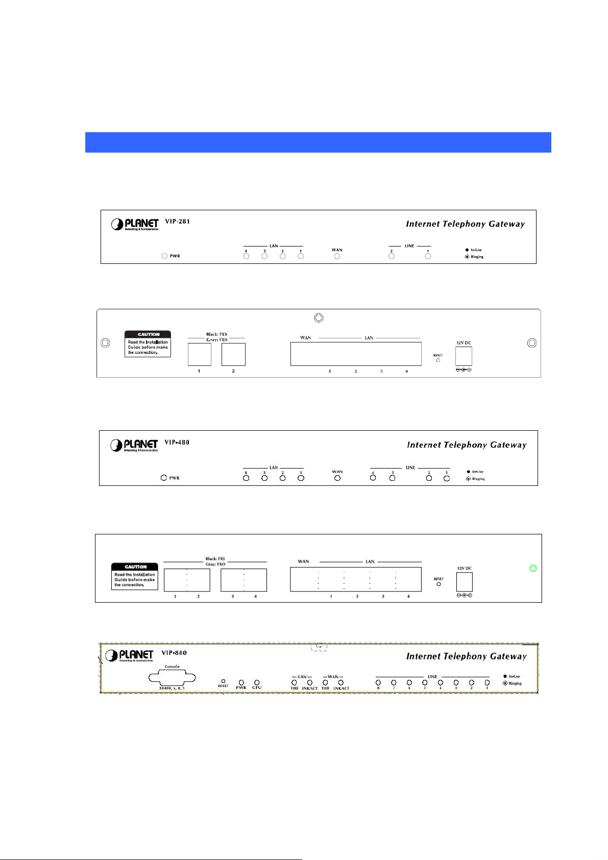
Physical Details
The following figure illustrates the front/rear panel of VIP-GW series:
Front Panel of VIP-281/VIP-281FS
Rear Panel of VIP-281/VIP-281FS
Front Panel of VIP-480/VIP-480FS/VIP-480FO
Rear Panel of VIP-480/VIP-480FS/VIP-480FO
Front Panel of VIP-880/VIP-880FS/VIP-880FO
9
Page 10
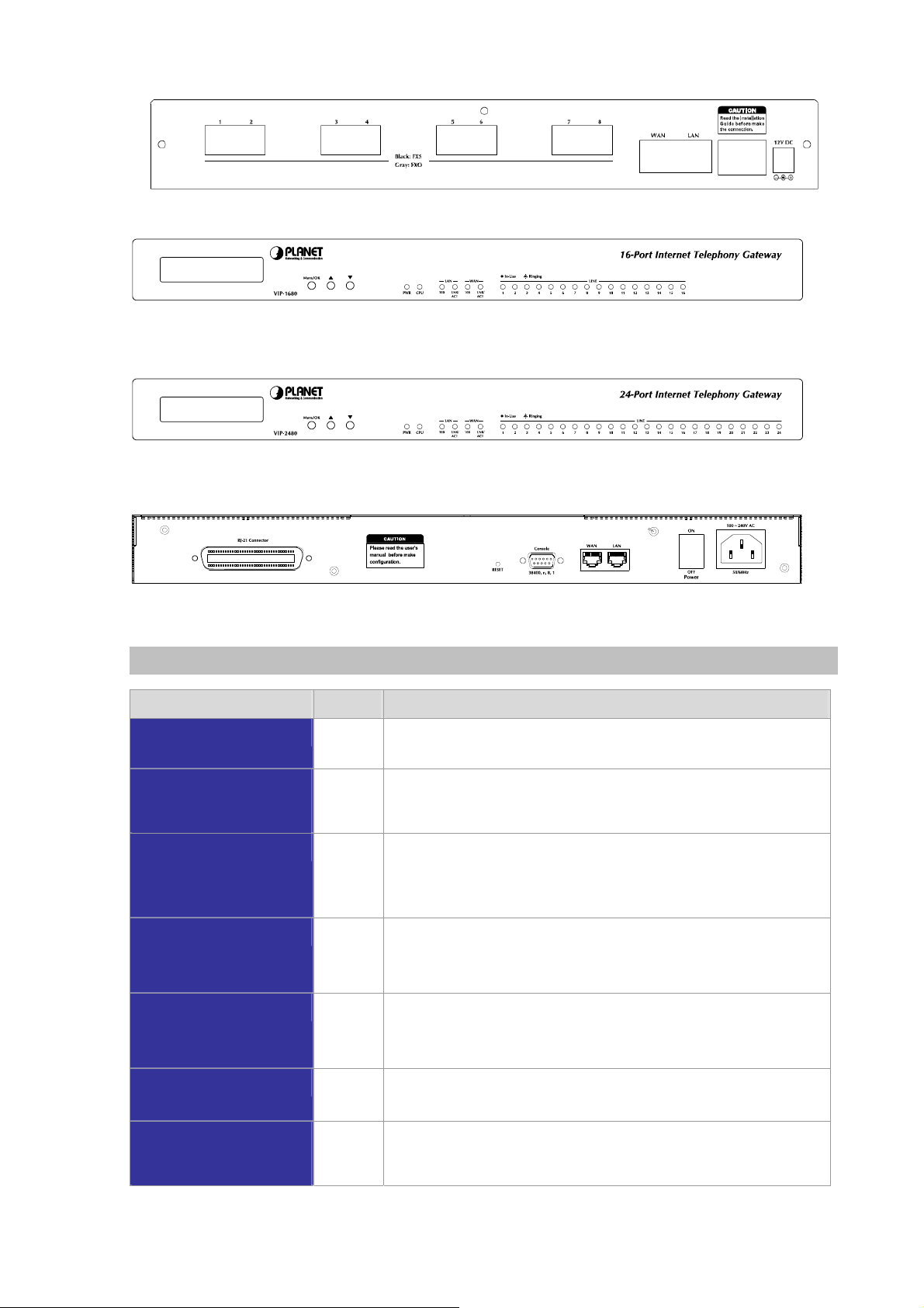
Rear Panel of VIP-880/VIP-880FS/VIP-880FO
Front Panel of VIP-1680/VIP-1680FS/VIP-1680FO/VIP-1680FD
Front Panel of VIP-2480/VIP-2480FS/VIP-2480FO/VIP-2480FD
Rear Panel of VIP-1680/VIP-1680FO/VIP-2480/VIP-2480FO
Front Panel LED Indicators & Rear Panels
Front Panel LED State Descriptions
PWR
CPU
(VIP-880 / VIP-1680 /
VIP-2480 series)
WAN Port
LAN Port
FXS
FXO
On
Off
Flashing
ON
Flashing
Off
ON
Flashing
Off
ON
Flashing
Off
On
Off
GW is powered ON
GW is powered Off
The system is running
GW network connection established
Data traffic on cable network
Waiting for network connection
LAN is connected successfully
Data is transmitting
Ethernet not connected to PC
Telephone Set is Off-Hook
Ring Indication
Telephone Set is On-Hook
Line is busy
Line is not enabled
LCD Panel
(VIP-1680/
VIP-2480 series)
On
Off
System is operation
System is Shutdown
10
Page 11
NOTE: System initialization will turn some LEDs ON for a few seconds.
A
Í
WAN
LAN
(VIP-880/VIP-1680/
VIP-2480 series)
LAN 1 ~ LAN 4
(VIP-281/VIP-480 series)
Reset
Power
FXS
Note
Rear Panel Descriptions
The Default LAN IP is http://192.168.0.1. Press RESET button
on rear panel over 5 seconds will reset the VoIP Gateway
to this default LAN/WAN IP address and Username/Password
function.
The WAN port supports auto negotiating Fast Ethernet 10/100Base-T
networks. This port allows your voice gateway to be connected to an
Internet
CAT.5 twisted pair Ethernet cable.
The LAN port supports 1/4 10/100Base-T switch hub networks. These 1/4
ports allow your PC or Switch/Hub to be connected to the voice gateway
through a CAT.5 twisted pair Ethernet cable.
The reset button, when pressed, resets the cable voice gateway without
the need to unplug the power cord.
Note: (the VIP-880 series in Front Panel)
The supplied power adapter connects here.
FXS port was connected to your telephone sets or Trunk Line of PBX.
ccess device, e.g. router, cable modem, ADSL modem, through a
FXO
Standard Telco 50 PIN
Connector (RJ-21)
9-pin RS-232
(VIP-880/VIP-1680/
VIP-2480 series)
FXO port was connected to the extension port of a PBX or directly
connected to a PSTN line of carrier.
It is a 50 pins RJ-21 connector for connecting to telephone patch panel.
Note: (the VIP-1680/VIP-2480 series only)
Connecting VIP to a terminal emulator for configuring VIP
Note: (the VIP-880 series in Front Panel)
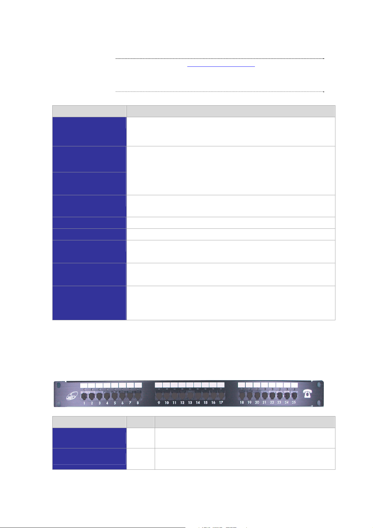
Connecting to the telephone patch panel (16-port/24-port model)
STEP 1: Attach the 25 port patch panel to the gateway through its RJ-21 connector.
STEP 2: The FXS LED indicators at telephone patch panel should be steady ON if the RJ-21 connector
is well connected to the gateway and the gateway is powered on.
Patch Panel LED State Descriptions
FXS
FXO
Note: The FXO interface is designed for connecting to PBXs (extension line) or central office switches
ON
Off
On
Off
Telephone Set is On-Hook
Telephone Set is Off-Hook
Line is not enabled
Line is In-using
11
Page 12

(CO line), and the FXS interface is designed for connecting to analog telephone sets or fax machines. If
the telephone cable connects to VIP-16/2480 series, the FXS interfaces are odd ports i.e. 1, 3, 5, 7, 9,
11, 13, 15, 17, 19, 21, 23, and the FXO interfaces are even ports, i.e. 2, 4, 6, 8, 10, 12, 14, 16, 18, 20,
22, 24.
Incorrectly connecting telephony devices to the RJ11 port
on the Telephony Interface can cause permanent damage to
the VoIP Gateway
12
Page 13

Chapter 2
2
Preparations & Installation
Physical Installation Requirement
This chapter illustrates basic installation of VIP-GW series
• Network cables. Use standard 10/100Base-TX network (UTP) cables with RJ45 connectors.
• TCP/IP protocol must be installed on all PCs.
For Internet Access, an Internet Access account with an ISP, and either of a DSL or Cable modem (for
WAN port usage)
Administration Interface
PLANET VIP-GW provides GUI (Web based, Graphical User Interface) for machine management and
administration.
Web configuration access
To start VIP-GW web configuration, you must have one of these web browsers installed on
computer for management
• Netscape Communicator 4.03 or higher
•
Microsoft Internet Explorer 4.01 or higher with Java support
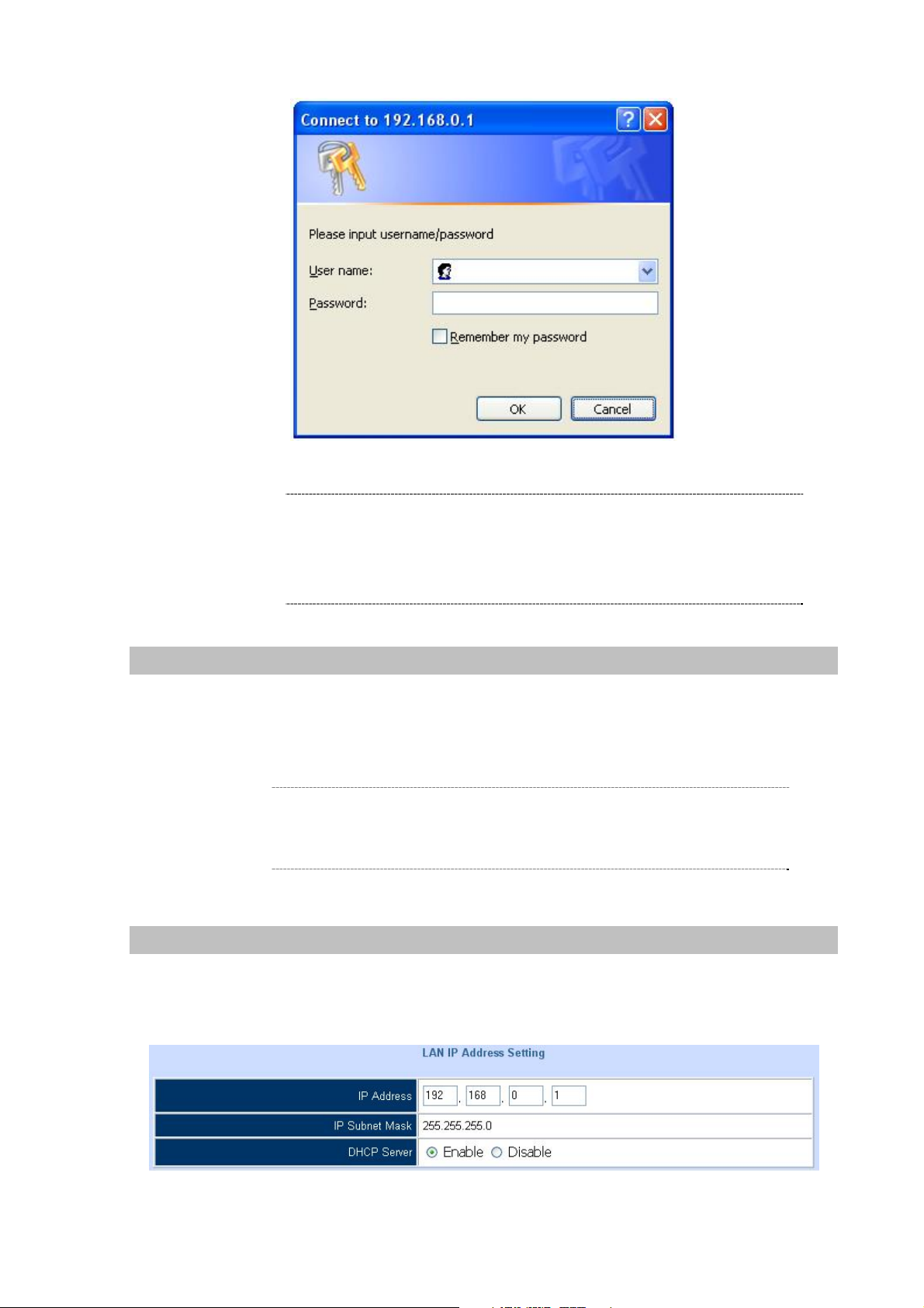
Default LAN interface IP address of VIP-GW is 192.168.0.1. You may now open your web browser, and
insert http://192.168.0.1 in the address bar of your web browser to logon VIP-GW web configuration
page.
VIP-GW will prompt for logon username/password, please enter: admin / 123 to continue machine
administration.
:
Page 14
Í
Note
Please locate your PC in the same network segment
(192.168.0.x) of VIP-GW. If you’re not familiar with TCP/IP,
please refer to related chapter on user’s manual CD or
consult your network administrator for proper network
configurations.
LAN/WAN Interface quick configurations
Nature of PLANET VIP-GW is an IP Sharing (NAT) device, it comes with two default IP addresses, and
default LAN side IP address is “192.168.0.1”, default WAN side IP address is “172.16.0.1”. You may
use any PC to connect to the LAN port of VIP-GW to start machine administration.
L
Hint
In general cases, the LAN IP address is the default gateway
of LAN side workstations for Internet access, and the WAN
IP of VIP-GW are the IP address for remote calling party
to connect with.
LAN IP address configuration via web configuration interface
Execute your web browser, and insert the IP address (default: 192.168.0.1) of VIP in the adddress bar.
After logging on machine with username/password (default: admin / 123), browse to “Advance Setup”
--> “LAN setting” configuration menu:
14
Page 15
Parameter Description
LAN IP address of VIP-GW
IP address
Subnet Mask
Default: 192.168.0.1
LAN IP address of VIP-GW
Default: 255.255.255.0
L
Hint
It is suggested to keep the DHCP server related parameters
in default state to keep machine in best performance.
After confirming the modification you’ve done, Please click on the Apply button to macke the changes
effective, and click “
Save Configuration”
to save configuration.
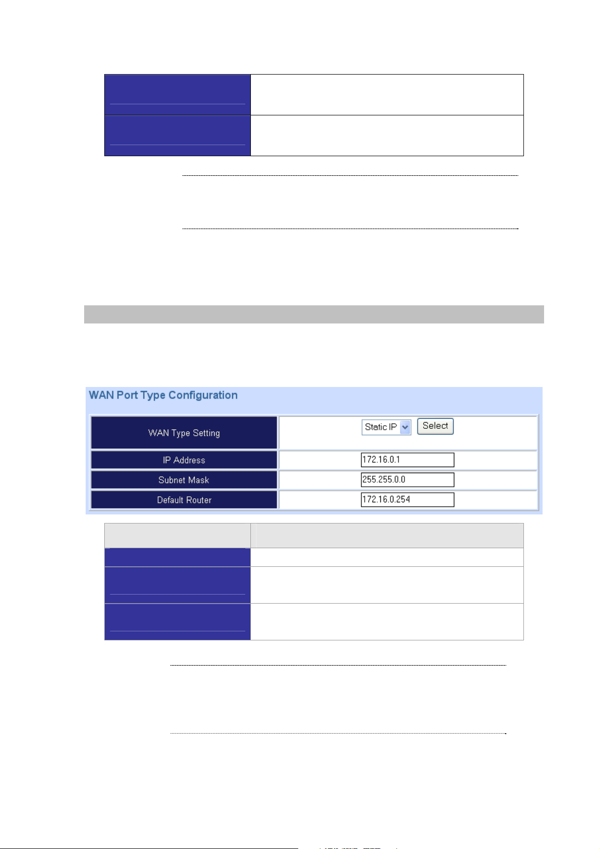
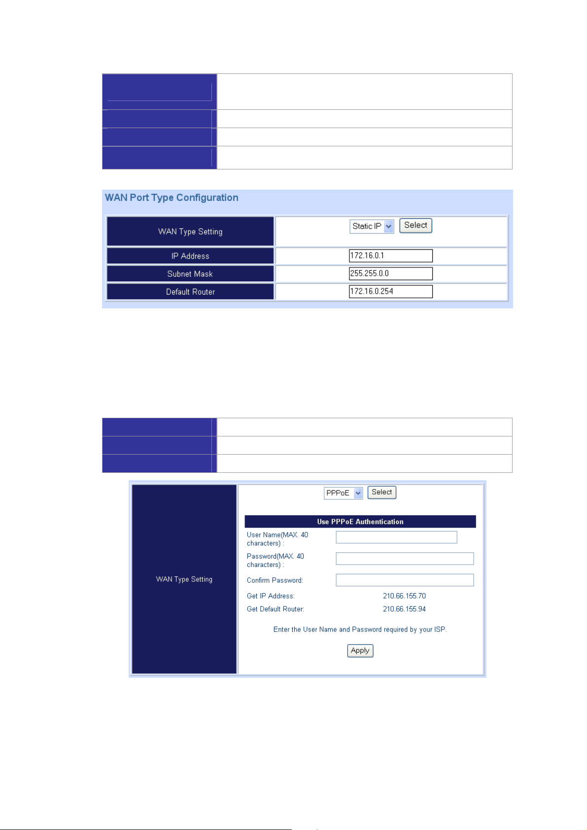
WAN IP address configuration via web configuration interface
Execute your web browser, and insert the IP address (default: 172.16.0.1) of VIP in the adddress bar.
After logging on machine with username/password (default: admin / 123), browse to “WAN Setting”
configuration menu, you will see the configuration screen below:
Connection Type Data required.
Static IP
The ISP will assign IP Address, and related information.
L
DHCP
PPPoE
Hint
Get WAN IP Address automatically; it is no need to configure the
DHCP settings.
The ISP will assign PPPoE username / password for Internet
access,
Please consult your ISP personnel to obtain proper PPPoE/IP
address related information, and input carefully.
If Internet connection cannot be established, please check
the physical connection or contact the ISP service staff
for support information.
15
Page 16
Chapter 3
3
Network Service Configurations
Configuring and monitoring your VoIP Gateway from web browser
The VIP-GW integrates a web-based graphical user interface that can cover most configurations and
machine status monitoring. Via standard, web browser, you can configure and check machine status
from anywhere around the world.
Overview on the web interface of VoIP Gateway
With web graphical user interface, you may have:
More comprehensive setting feels than traditional command line interface.
Provides user input data fields, check boxes, and for changing machine configuration settings
Displays machine running configuration
To start VIP-GW web configuration, you must have one of these web browsers installed on computer
for management
Netscape Communicator 4.03 or higher
Microsoft Internet Explorer 4.01 or higher with Java support
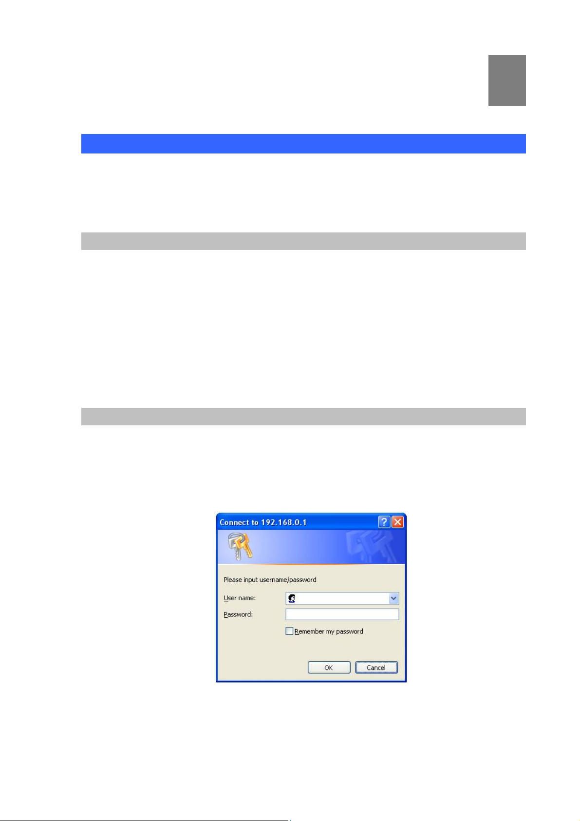
Manipulation of VoIP Gateway via web browser
Log on VoIP Gateway via web browser
After TCP/IP configurations on your PC, you may now open your web browser, and input
http://192.168.0.1 to logon VoIP gateway web configuration page.
VoIP gateway will prompt for logon username/password: admin / 123
VIP-GW log in page
Page 17
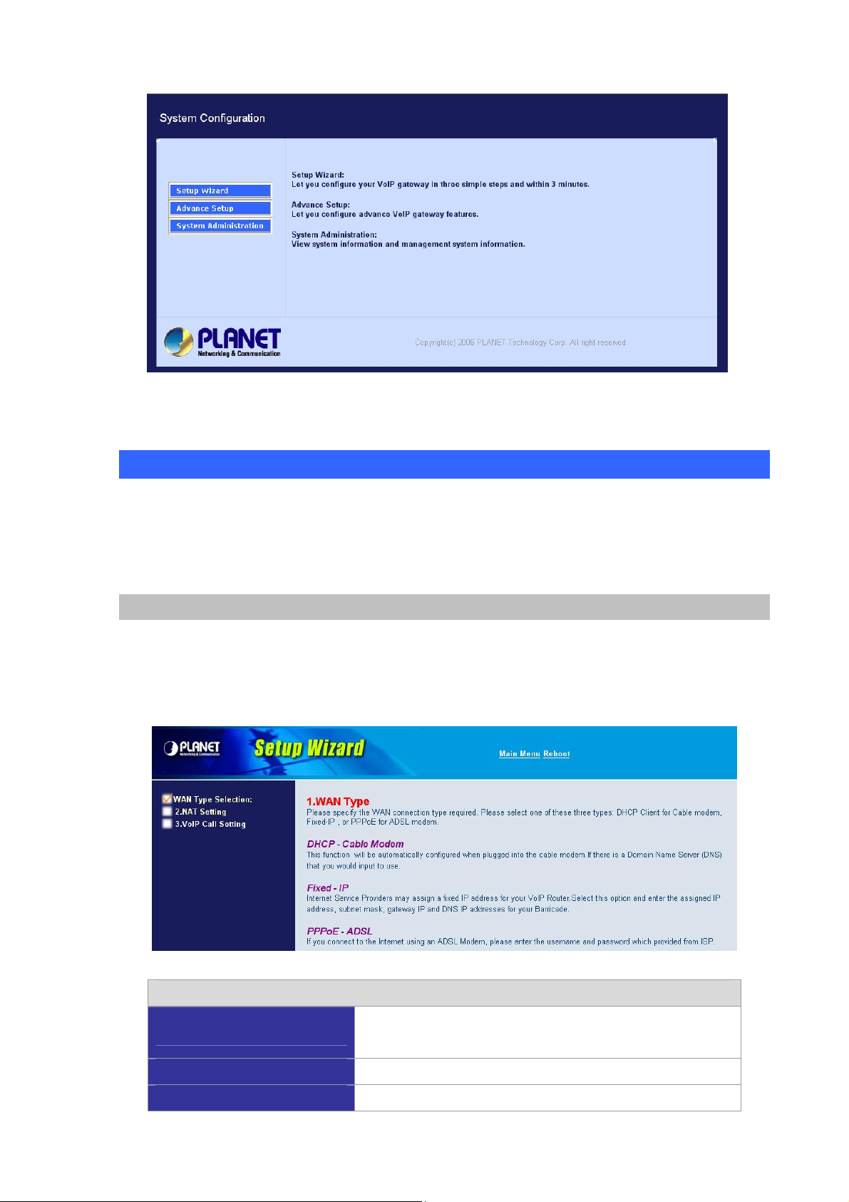
VIP-GW main page
Wizard Setup for Quick Start
Wizard Setup
After finishing the authentication, the Main menu will display 3 parts of configuration, please click
“Wizard Setup” to enter quick start:
1. WAN Port Type Setup (Setup First)
For most users, Internet access is the primary application. The VIP-GW support the WAN interface for
Internet access and remote access. The following sections will explain more details of WAN Port
Internet access and broadband access setup. When you click “WAN Port Type Setup” from within the
Wizard Setup, the following setup page will be show:
Three methods are available for Internet Access
Fixed IP User
IP Address
Netmask
If you are a leased line user with a fixed IP address, fill out the
following items with the information provided by your ISP.
check with your ISP provider
check with your ISP provider
17
Page 18
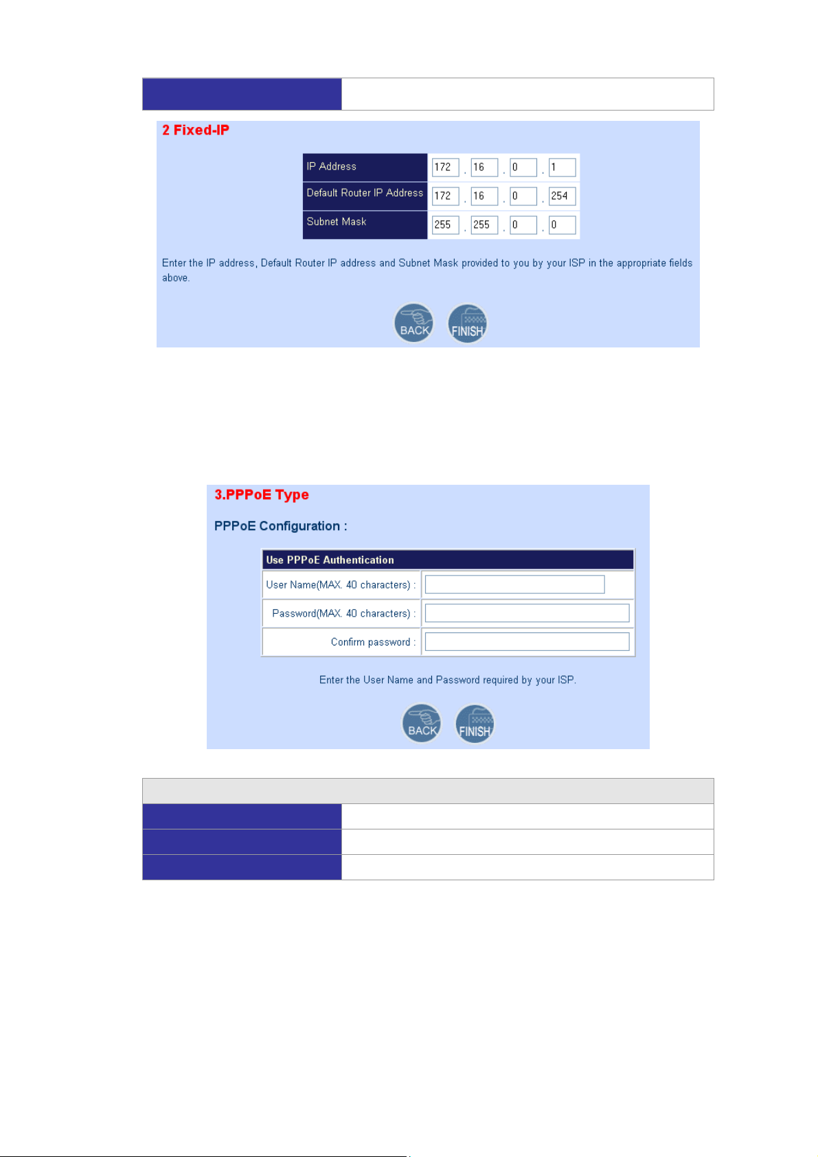
Default Gateway
check with your ISP provider
ADSL Dial-Up User (PPPoE Enable)
Some ISPs provide DSL-based service and use PPPoE to establish communication link with end-users.
If you are connected to the Internet through a DSL line, check with your ISP to see if they use PPPoE. If
they do, you need to select this item.
Three methods are available for Internet Access
User Name
Password
Retype Password
Enter User Name provided by your ISP
Enter Password provided by your ISP
Enter Password to confirm again
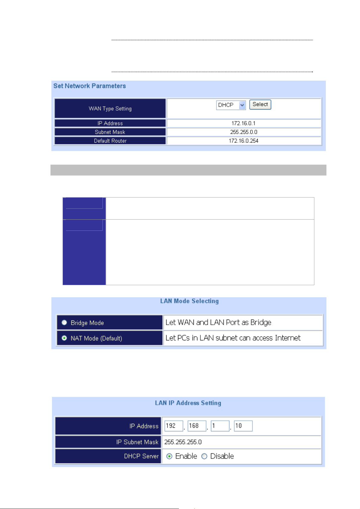
DHCP Client (Dynamic IP): (Get WAN IP Address automatically)
IP Address: If you are connected to the Internet through a Cable modem line then a dynamic IP
address will be assigned.
18
Page 19
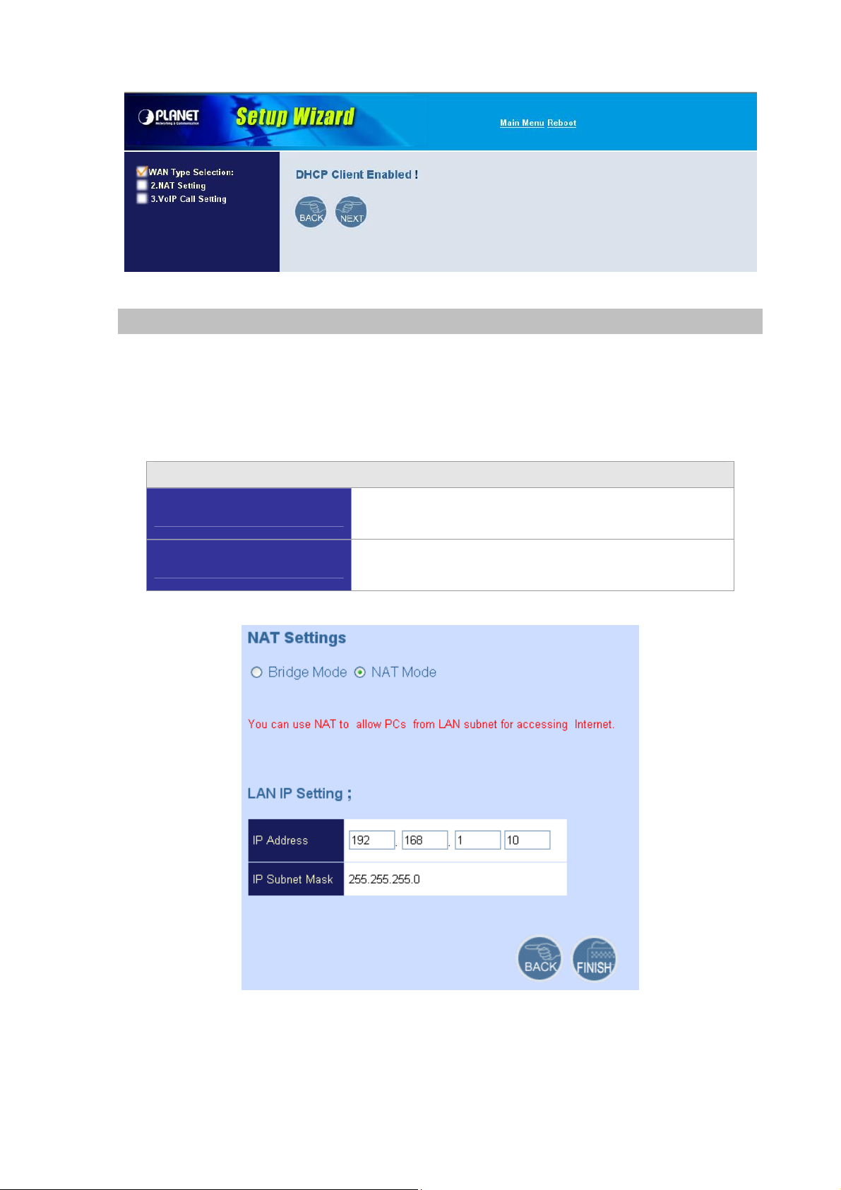
2. Configuring NAT or Bridge setting:
Bridge Mode:
When working on Bride Mode, the VoIP gateway will use only the LAN setting IP, The VIP-GW will use
the same LAN IP setting as WAN IP. That means, when Bride mode enable, the WAN connection
setting will be ignored.
NAT mode:
LAN IP Network Configuration
IP Address
Subnet Mask
Private IP address for connecting to a local private network
(Default: 192.168.0.1)
Netmask for the local private network
(Default: 255.255.255.0)
19
Page 20
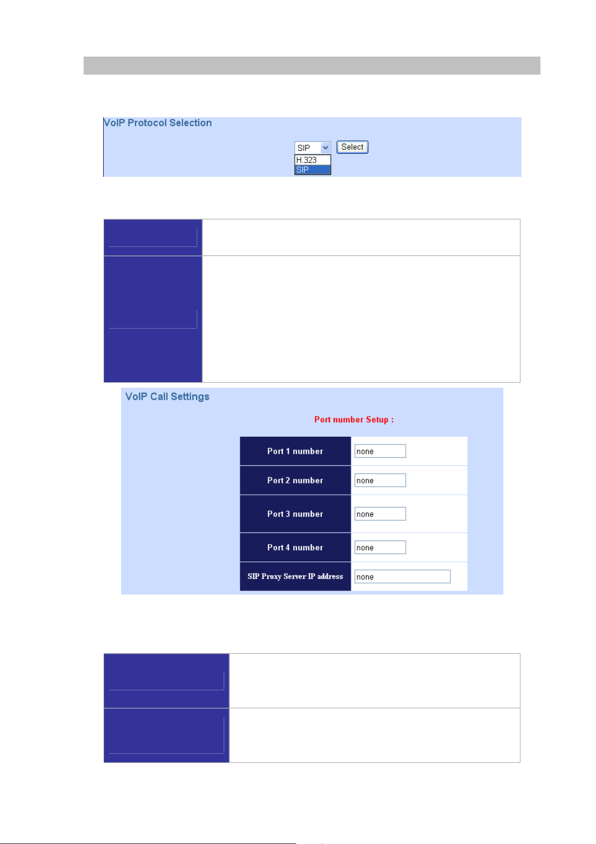
3. VoIP Call Protocol Setup
STEP 1 : Configure VoIP Call Signal Protocols :
User could select either H.323 or SIP Protocol, and click “select”
STEP 2 : Configure the numbering with phone/line ports
Phone Number
Line Number
The representation number is the phone number of the telephone that
is connected to phone port
Line ports are connected to the extension ports of the PBX system or
the PSTN line. They have a common Line Hunting Group Number.
When this number is dialed, the VIP-GW system will find a free FXO
line connected to PBX. This hunting will skip all busy lines and absent
lines and find only the idle line to the PBX. After the available line is
found, you can hear the dial tone from PBX. After that, you can dial
the needed phone number out through PBX
STEP 3: Let VIP-GW register to Gatekeeper/SIP Proxy Server
Note: If user does not have Gatekeeper/SIP proxy server, please go to STEP 4: Outgoing Dialing Plan
There is a gatekeeper address fields. If this gateway does not
Gatekeeper IP address
SIP Proxy Server IP
addresses
want to register to any gatekeeper, just set value 0.0.0.0 to the
primary Gatekeeper address.
There is a SIP proxy server address fields. If this VIP-GW does
not want to register to any SIP proxy server, just set value
0.0.0.0 to the sip proxy server address.
20
Page 21
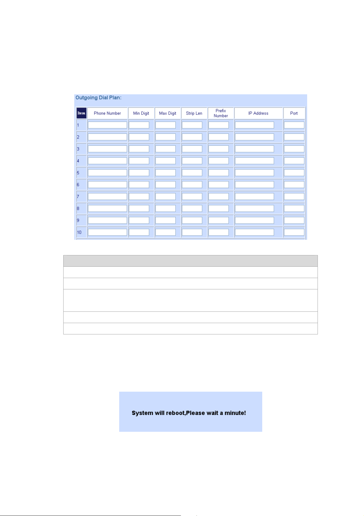
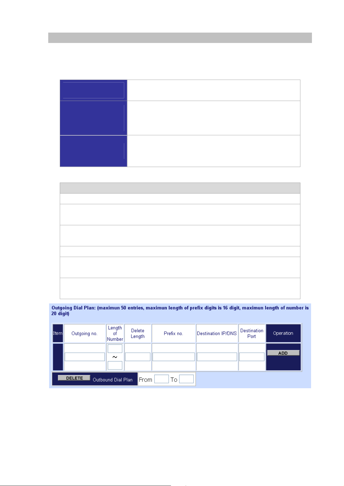
STEP 4: Outgoing Dialing Plan
The purpose of “Outgoing Direct Call” setting is to let user create a proprietary dialing plan when this
Gateway is not registered to any H.323 Gatekeeper or any SIP proxy server. This setting can also
assign some dialing plan to local ports (including prefix strip, prefix addition).
Through this setting, user can directly map a number to a specific gateway (IP address).
In the “Outgoing Dial Plan” settings: Maximum Entries : 50
“Leading Number” is the leading digits of the dialing number.
“Min Length” and “Max Length” is the min/max allowed length you can dial.
“Strip Length” is the number of digits that will be stripped from beginning of the dialed
number.
“Prefix Number” is the digits that will be added to the beginning of the dialed number.
“Destination” is the IP address of the destination gateway that owns this phone number
STEP 5: Finishing the Wizard Setup
After completing the Wizard Setup, please click “Finish” bottom. The VIP-GW will save the
configuration and rebooting gateway automatically. After 20 Seconds, you could re-login the machine.
21
Page 22
Chapter 4
System Configurations
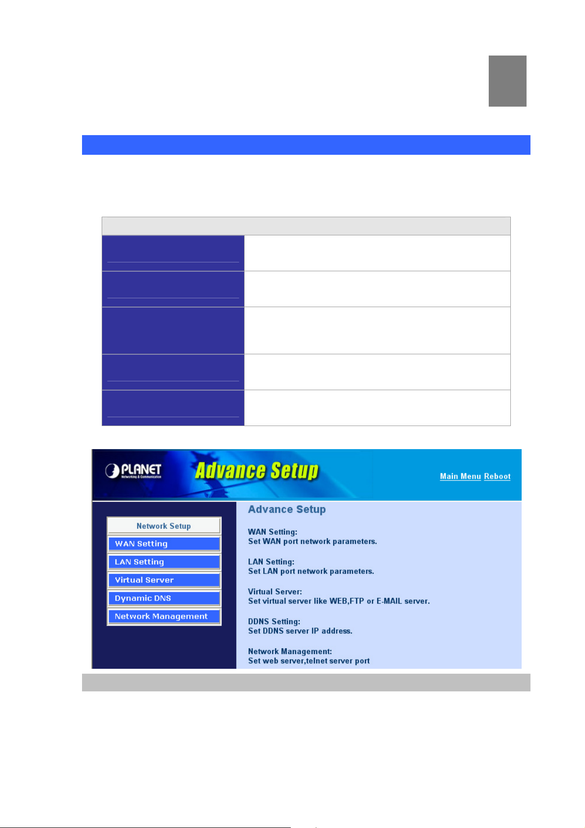
Advance Setup of Network Setup
In Advanced Setup, VIP-GW provides user two major parts function to configure:
One is “Network Setup”, the other one is “VoIP Call Setup”
Network Setup Label
4
WAN Setting
LAN Setting
Virtual Server
Dynamic DNS
Network Parameters
Sets/changes the WAN port type like “Fixed IP”, “DHCP
Client” or ”PPPoE”.
Modifies the IP address of the LAN port and setting DHCP
server parameters.
Remote user can access server such as Web or FTP at
you local site vi。pa public IP address can be automatically
redirected to local servers configured with private IP
address.
Dynamitic DNS allows you to provide Internet users with a
domain name to access your server.
Network parameter allows you to modify the access port of
gateway.
WAN Setting
For most users, Internet access is the primary application. The VIP-GW series support the WAN
interface for Internet access and remote access. The following sections will explain more details of
WAN Port Internet access and broadband access setup. When you click “WAN Setting”, the following
setup page will be shown.Three methods are available for Internet access.
Page 23
Static IP
IP Address
Netmask
Default Gateway
PPPoE for ADSL
Some ISPs provide DSL-based service and use PPPoE to establish communication link with end-users.
You are a leased line user with a fixed IP address; fill out the
following items with the information provided by your ISP
Kindly please check with your ISP provider
Kindly please check with your ISP provider
Kindly please check with your ISP provider
If you are connected to the Internet through a DSL line, check with your ISP to see if they use PPPoE. If
they do, you need to select this item.
User Name
Password
Retype Password
Enter User Name provided by your ISP
Enter Password provided by your ISP
Enter Password to confirm again
DHCP client (Dynamic IP): (get WAN IP address automatically)
IP Address: If you are connected to the Internet through a Cable modem line then a dynamic IP
address will be assigned.
23
Page 24
L
Note
WAN port display the IP address, Subnet Mask and default
gateway IP address if DHCP client is successful
LAN Setting
There are two kinds of network feature to configure: Bridge Mode and NAT Mode:
Bridge Mode
NAT Mode
LAN IP Network Configuration
IP Address: Private IP address for connecting to a local private network (Default: 192.168.0.1).
Select this VIP-Gw as Bridge. (WAN Port and LAN Port use the same IP
address)
Each of the VIP-GW has two Ethernet interfaces, one is for connecting to
local network users, and the other is for connecting to an external
broadband device (i.e. DSL modem/router or Cable modem). The LAN port
is connected to the local Ethernet network. WAN is connected to the
external broadband device. The LAN IP address/netmask is for private
users or NAT users, and the WAN IP address/netmask is for public users.
Subnet Mask: Netmask for the local private network (Default: 255.255.255.0).
24
Page 25
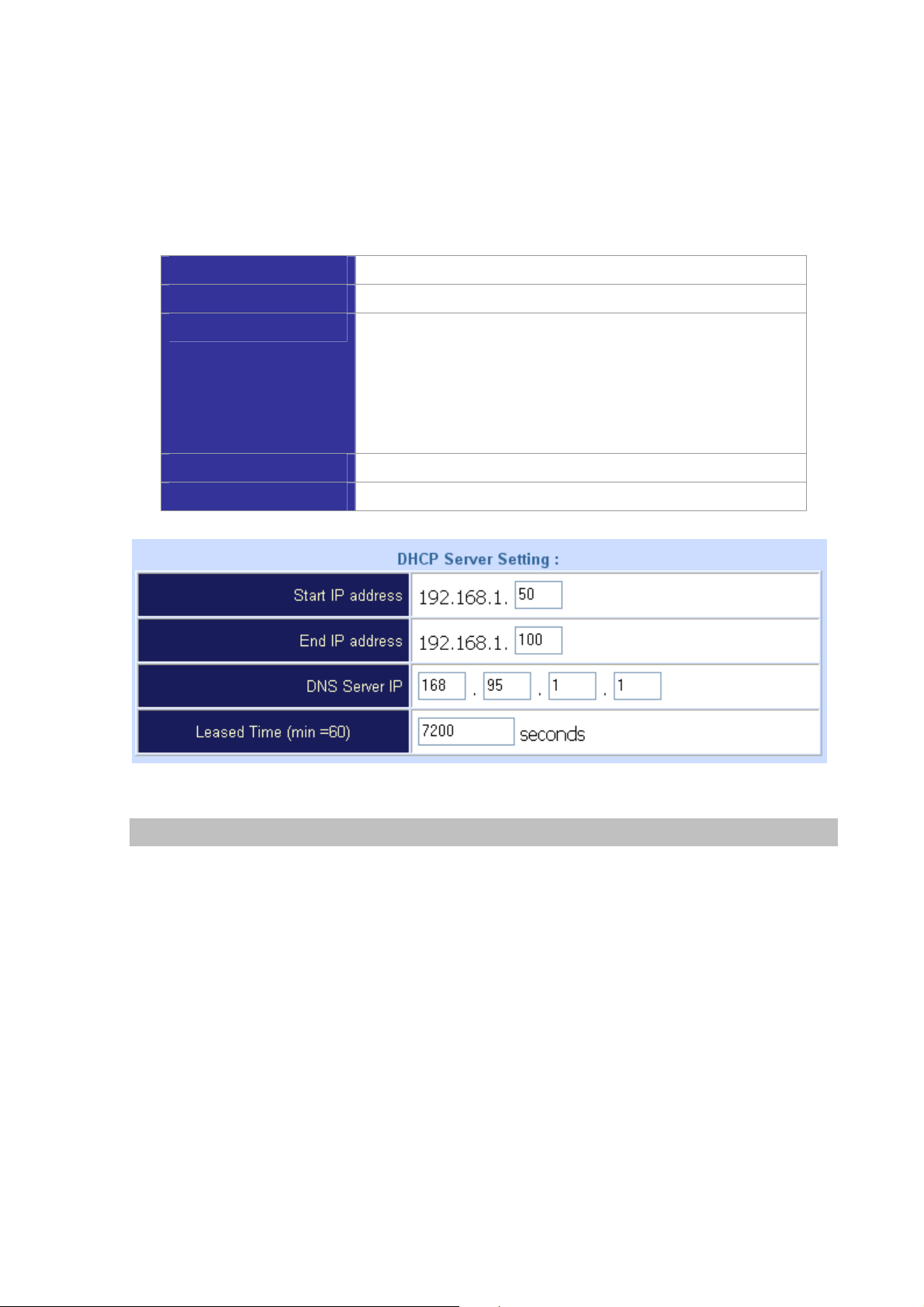
DHCP Server Configuration
DHCP stands for Dynamic Host Configuration Protocol. It can automatically dispatch related IP settings
to any local user configured as a DHCP client. The DHCP server supports up to 253 users (PCs) on
Yes: Enables the DHCP server. No: Disables the DHCP server.
Start IP Address
End IP Address
DNS Server IP Address
Primary IP Address
Secondary IP Address
Sets the start IP address of the IP address pool.
Sets the end of IP address in the IP address pool.
DNS stands for Domain Name System. Every Internet host.
must have a unique IP address, also they may have a human
friendly, easy to remember name such as www.yahoo.com. The
DNS server converts the human friendly name into it’s
equivalent IP address.
Sets the IP address of the primary DNS server.
Sets the IP address of the secondary DNS server.
Virtual Server
“Natural firewall” allows requests for Internet access from the local network. However, any request from
the Internet to the local network is blocked. By setting the Virtual Server function, computers outside
the Intranet are allowed to access specific ports of local client. The Virtual Server Port Table may be
used to expose internal servers to the public domain or open a specific port number to internal hosts.
Internet hosts can use the WAN IP address to access internal network services, such as FTP, WWW,
and Telnet etc.
How to set a Virtual Server
The following example shows how an internal FTP server is exposed to the public domain. The internal
FTP server is running on the local host addressed as 192.168.0.100.
25
Page 26
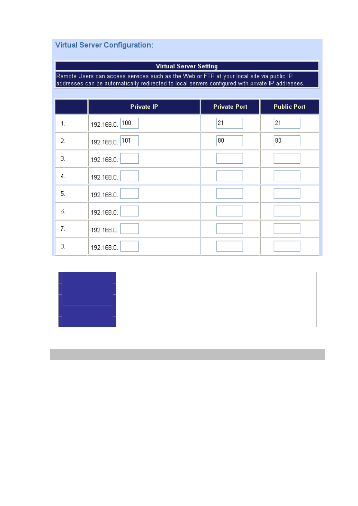
Public Port
Private IP
Private Port
Apply
Specifies which port should be redirected to the internal host.
Specifies the private IP address of the internal host offering the service.
Specifies the private port number of the service offered by the internal
host.
Click here to add the port-mapping entry and enable the service.
Dynamic DNS
DDNS is a service that maps Internet domain names to IP addresses. DDNS serves a similar purpose
to DNS: DDNS allows anyone hosting a Web or FTP server to advertise a public name to prospective
users. Unlike DNS that only works with static IP addresses, DDNS works with dynamic IP addresses,
such as those assigned by an ISP or other DHCP server. DDNS is popular with home network, who
typically receive dynamic, frequently-changing IP addresses from their service provider. To use DDNS,
one simply signs up with a provider and installs network software on their host to monitor its IP address.
26
Page 27
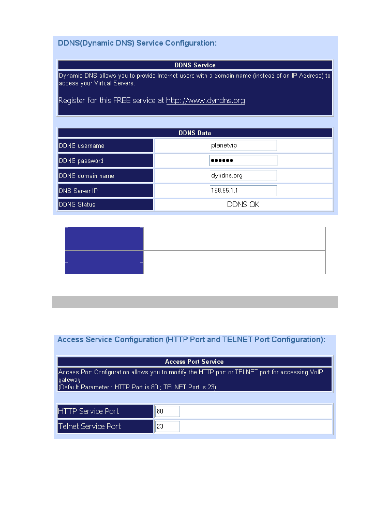
User Name
Password
Domain Name
DNS Server IP
Input your DDNS User Name
Input your DDNS Password
Input you set from your DDNS
Input your DNS Server IP
Netwrok Management
Network Parameter allows you to modify the access port of gateway.
For example: Setting HTTP port: 80 and Setting TELNET port: 23
27
Page 28
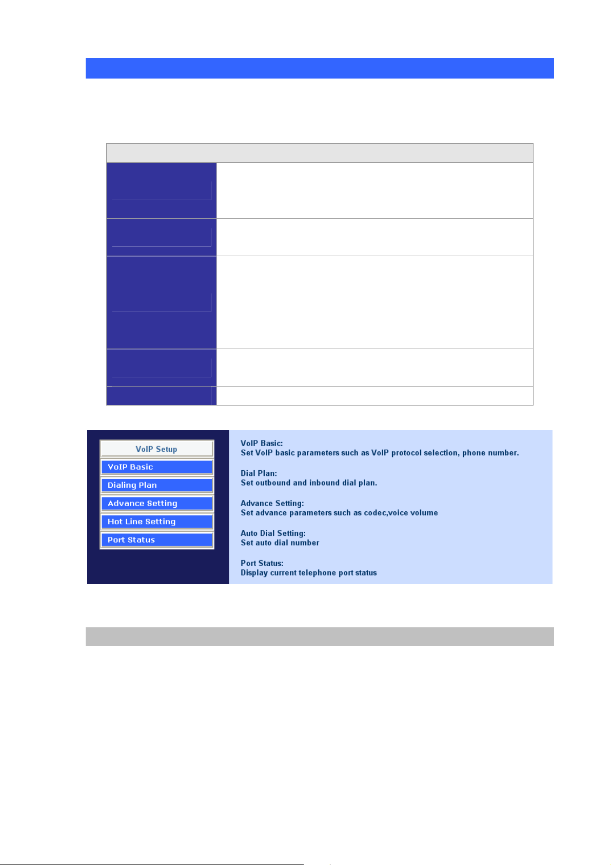
Advance Setup of VoIP Setup
In Advanced Setup, VIP-GW provides user two major parts function to configure:
One is “Network Setup”, the other one is “VoIP Call Setup”
VoIP Setup Label
The PLANET series gateway support 2~24 phone/line for SIP and
VoIP Basic
Dialing Plan
Advanced Setting
Hot Line Setting
Port Status
H.323 VoIP call applications. You can configure these ports from
this menu.
Users could apply any dial policy by setting Dial Plan including
outgoing dial plan and incoming dial plan.
VIP-GW support for silence compression, DTMF Relay, Codec
Selection, FAX mode Option,
H323 Register Type and H.323 Fast-Start/Normal-Start function.
FXO AC impedance, Volume Adjustment, RRQ TTL, RFC2833
Payload, IP TOS,..etc
Let user can set up “hotline” to dial the phone number
automatically.
Display the telephone interface status
VoIP Basic Configuration to H.323 protocol
VoIP Basic Configuration: (Configure the VoIP protocol to H.323 Protocol)
28
Page 29

Configure the numbering with FXS / FXO ports. (Depending on GW model number: if user uses the
model number is VIP-1680, this VIP-1680 has 16 voice channels for setting, and the VIP-2480 had 24
voice channels for setting)
FXS Number
The representation number is the phone number of the telephone that is
connected to FXS port.
FXO ports are connected to the extension ports of the PBX system or
the PSTN line. They have a common Line Hunting Group Number.
When this number is dialed, the VIP-GW system will find a free FXO line
FXO Number
connected to PBX. This hunting will skip all busy lines and absent lines
and find only the idle line to the PBX. After the available line is found,
you can hear the dial tone from PBX. After that, you can dial the needed
phone number out through PBX.
Configure the ANI (Answer Number Indication) / Caller ID of the FXS/FXO ports
ITSP needs ANI for authorization when gateway calls Off-Net call to PSTN number or mobile phone
number.
Register to H.323 Gatekeeper server
Note: If user does not have Gatekeeper, please go to H.323 Dialing Plan Policy for more
understandings.
29
Page 30

H.323 Parameters Label
H.323 ID
Primary Gatekeeper IP
Address
Secondary Gatekeeper IP
Address
Primary Gatekeeper Domain
Name
Secondary Gatekeeper
Domain Name
H.323 Gatekeeper ID
Sets the unique name of this Gateway, that is
communicated as part of H.323 messaging.
There are two gatekeeper address fields, one is primary,
the other secondary. If this gateway does not want to
register to any gatekeeper, just set value 0 to the primary
gatekeeper address. If the primary gatekeeper address is
not 0, the gateway will register to the primary gatekeeper. If
the second gatekeeper is not 0, the gateway will try to
register to the second gatekeeper when failed to register to
primary gatekeeper, i.e. if both the primary gatekeeper and
second gatekeeper
Let user use Domain Name of H.323 Gatekeeper.
The Gatekeeper ID; usually do not need to set this field
unless the gatekeeper must need this value.
Voice Cap Prefix
30
Let user set prefix number in RRQ nonstandard voicecap
entry.
Page 31

In H.323 standard the RAS default port number is 1719.
RAS Port Adjustment
Q.931 Port Adjustment
H.323 Call Pass through NAT
H.323 ID
H.323 Pass Through NAT
method
The VoIP gateway provides user to change RAS port
number to meet the network environment.(Some area
carrier blocks or forbidden the default port number)
In H.323 standard the default Q.931 port number is 1720.
The VoIP gateway provides user to change Q.931 port to
meet the network environment. (Some area carrier blocks
or forbidden the default port number)
Sets the unique name of this Gateway, that is
communicated as part of H.323 messaging.
1. Disable : The Gateway operates in public IP address
2. Auto Detection: When the Gateway register to GNU
Gatekeeper, please select this option.
3. Manual Setting: When the Gateway registers to H.323
Gatekeeper and operate under NAT (enable DMZ), please
select this option and key in IP address.
Dialing Plan to H.323 protocol
The “Dialing plan” needs setting when the user uses the method of Peer-to-Peer H.323 VoIP call or
registering H.323 Gatekeeper mode. The H.323 Dialing Plan has three kinds of directions: Outgoing
(call out) and Incoming (call in) and PSTN route.
Outgoing Dial Plan
Incoming Dial Plan
PSTN Route Dial Plan
In the “Outgoing Dial Plan Configurations” settings: Maximum Entries : 50
Peer-to-Peer call mode: Effective
Registering to H.323 Gatekeeper mode: Effective
Peer-to-Peer call mode: Effective
Registering to H.323 Gatekeeper mode:
The leading number would register to H.323 Gatekeeper
Peer-to-Peer call mode: The same as the Incoming dial plan
Registering to H.323 Gatekeeper mode: The leading number
would NOT register to H.323 Gatekeeper
“Outbound number” is the leading digits of the call out dialing number.
“Length of Number” has two text fields need filled: “Min Length” and “Max Length” is the
min/max allowed length you can dial.
“Delete Length” is the number of digits that will be stripped from beginning of the dialed
number.
31
Page 32

“Add Digit Number” is the digits that will be added to the beginning of the dialed number.
“Destination IP Address / Domain Name” is the IP address / Domain Name of the
destination gateway that owns this phone number.
Scenario description: Normally dial
001x leading call out, call to destination IP address: 172.16.0.100
002x leading call out, call to destination domain name: h323gw.test.com
Scenario description: Speed dial
If user dials “101”, the gateway automatically dials “1234567890” to destination IP address:
172.16.0.101
If user dials “202”, the gateway automatically dials “0987654321” to destination IP address:
172.16.0.202
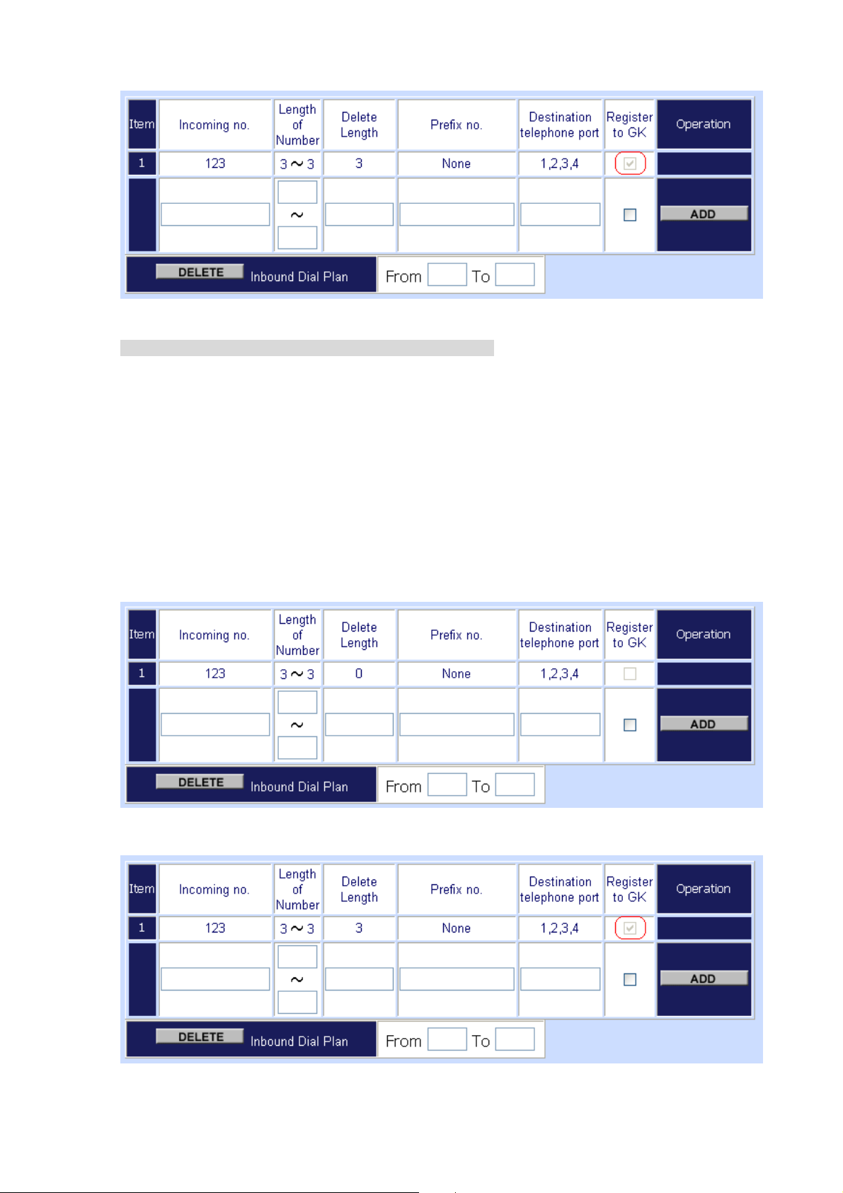
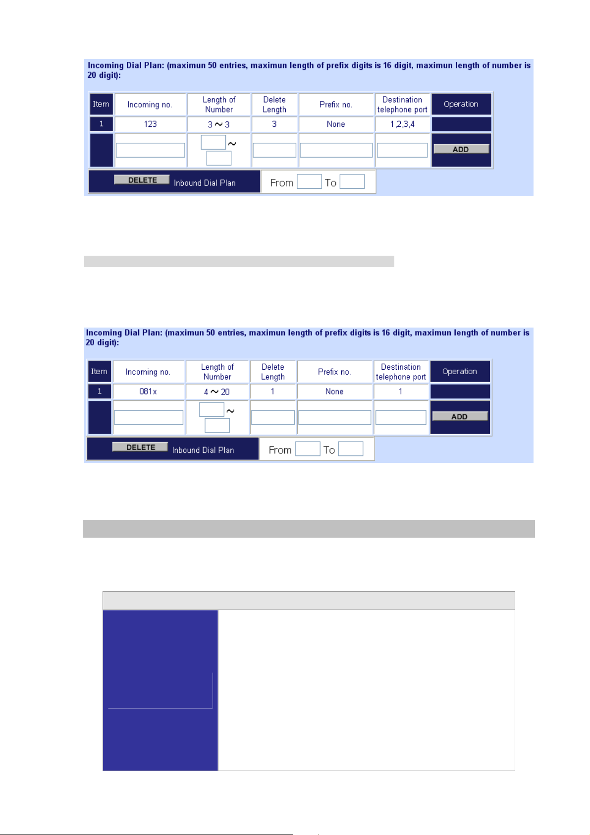
In the “Incoming Dial Plan Configurations” settings: Maximum Entries : 50
“Inbound number” is the leading digits of the dialing number.
32
Page 33

“Length of Number“ has two text fields need filled: “Min Length” and “Max Length” is the
min/max allowed length you can dial.
“Delete Length” is the number of digits that will be stripped from beginning of the dialed
number.
“Add Digit Number” is the digits that will be added to the beginning of the dialed number.
“Destination telephone port” is “FXS/FXO port number” ; this is for local dial plan setting
phone number.
Scenario description: Hunting for FXS port (VIP-480FS)
Port 1: FXS
Port 2: FXS
Port 3: FXS
Port 4: FXS
H.323 number “123” call incoming, the port 1 will be ringing.
If port 1 is busy, the port 2 will be ringing.
If port 1 and port 2 are busy, the port 3 will be ringing.
If port 1, port 2 and port 3 are busy, the port 4 will be ringing.
Note: “123” will be register to H.323 Gatekeeper if “Register to GK” was enabled, show as below:
33
Page 34
Scenario description: Hunting for FXO port (VIP-480FO)
Port 1: FXO was connected to PSTN.
Port 2: FXO was connected to PSTN.
Port 3: FXO was connected to PSTN.
Port 4: FXO was connected to PSTN.
H.323 number “123” call incoming, the port 1 will be off-hook and hear the dial tone from PSTN.
If port 1 is busy, the port 2 will be will be off-hook and hear the dial tone from PSTN.
If port 1 and port 2 are busy, the port 3 will be off-hook and hear the dial tone from PSTN.
If port 1, the port 2 and port 3 are busy, the port 4 will be off-hook and hear the dial tone from
PSTN.
Note: “123” will be register to H.323 Gatekeeper if “Register to GK” was enabled, show as below:
34
Page 35
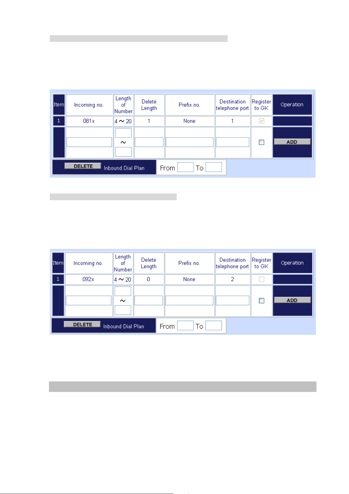
Scenario description: Termination call to FXO for one-shoot call
Port 1: FXO was connected to PSTN (area code is 81xxxxxxxx).
H.323 leading number “081x” incoming, and delete the first one digit “0”, and call to PSTN
number.
Note: “081x” will be registered to H.323 Gatekeeper if “Register to GK” was enabled, show as below:
Scenario description: Termination call to FXO
Port 1: FXS
Port 1: FXO was connected to PSTN (area code is 92xxxxxxxx).
Port 1 FXS call to “092x” to PSTN, the FXO port will delete the first one digit “0” and call to PSTN
number.
Note: “092x” will be NOT register to H.323 Gatekeeper when gateway when registering H.323
Gatekeeper mode
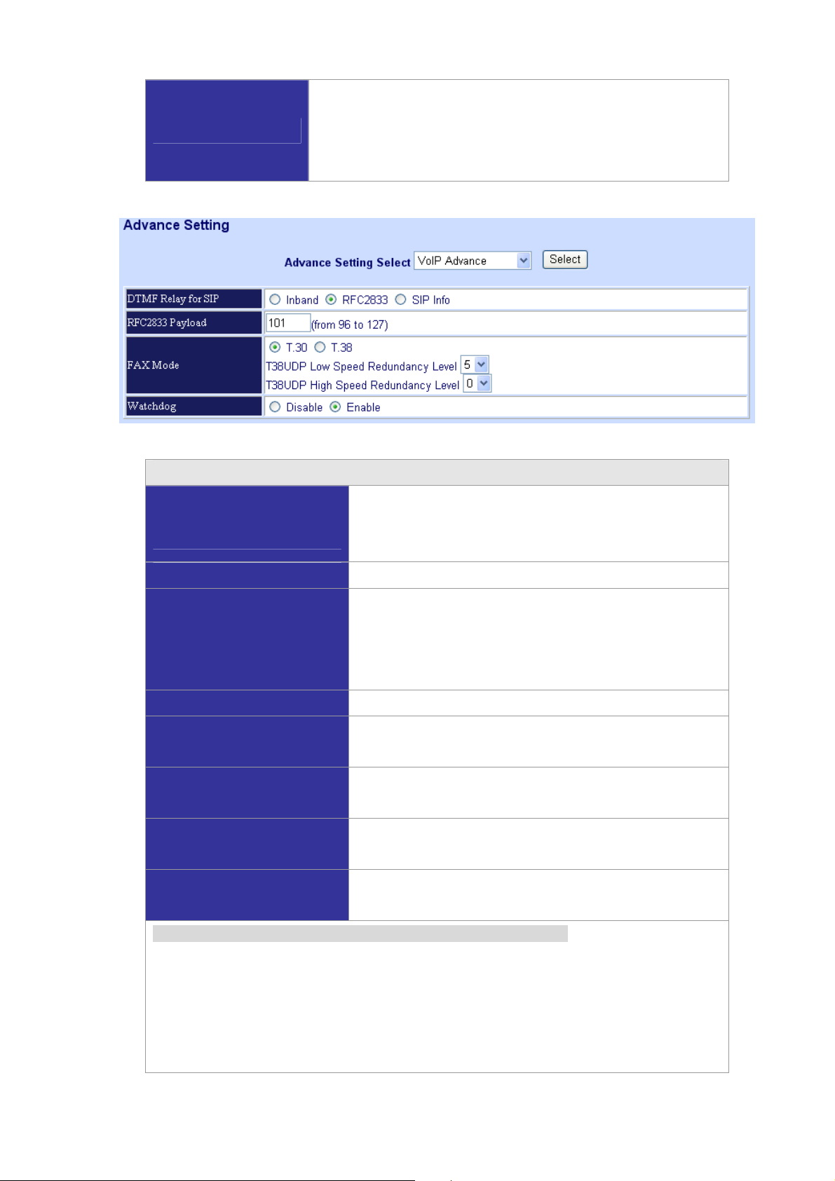
Advance Setting to H.323 protocol
In Advanced Setting , VIP-GW provides user three major parts function to configure:
One is “VoIP Advanc e ”, the other one is “Telephone Advance” and “Network Advance”
35
Page 36

H.323 VoIP Advance Configurtion
Smart-QoS
DTMF Relay for H.323
H.323 Start Mode
If this function is enabled, when VoIP call is occurred, the other
data will be automatically reduced traffic which across the
internet in order to guarantee the voice bandwidth.
After the VoIP call is connected, when you dial a digit, this digit
is sent to the other side by DTMF tone. There are two methods
of sending the DTMF tone. The first is “in band”, that is, sending
the DTMF tone in the voice packet. The other is “out band”, that
is, sending the DTMF tone as a signal. Sending DTMF tone as
a signal could tolerate more packet loss caused by the network.
If this selection is enabled, the DTMF tone will be sent as a
signal.
This selection could force the gateway to use normal start mode
(default mode) or fast start mode when establishing a VoIP call.
Many other gateways only support normal start mode, enable
this selection when it is necessary. The default is disabled
(using fast start mode).
This selection could force the gateway to use normal start mode
H.323 H.245 Tunneling
FAX Mode Option
(default mode) or fast start mode when establishing a VoIP call.
Many other gateways only support normal start mode, enable
this selection when it is necessary. The default is disabled
(using fast start mode).
T.30/T.38 real-time FAX compliant Voice/FAX auto-switch.
36
Page 37

The T.38 is a “Real Time Group 3 FAX communication over IP
network” format. That’s meaning it’s a protocol for Fax over IP.
You have to enable this function.
This command configures the number of seconds that the
H.323 RRQ TTL
gateway should be considered active by the H.323 Gatekeeper.
The gateway transmits this value in the RRQ message to the
gatekeeper.The default value is “0”.
There are 2 choices for this setting. “Gateway” means it will act
H.323 Registration type
as the VIP-GW. “Terminal” means it will act as the IP phone
terminal.
H.323 Telephone Advance Configuration
If this function is enabled, when silence is occurred for a period
Silence Compression
of time, no data will be sent across the network during this
period in order to save bandwidth.
Dial Complete Tone
Disable / Enable dialing complete tone.
The codec is used to compress the voice signal into data
Voice Codec option
packets. Each codec has different bandwidth requirement.
There are four kinds of codec, G.7 2 3 , G. 7 29 A B, G. 711_ u and
G.711_A. The default value is G.723.
FXS Impedance
FXO AC Impedance
Phone (Line) in/out
volume
FXO Tx/Rx Gain
UK PSTN release tone
detection
The FXS provides 600/900 OHM impedances for selection.
The FXO provides wild and complex ac termination
impedances for selection.
You can adjust the Phone (Line) in/out volume, range from -9db
to 9db.
You can adjust the FXO Tx/Rx Gain, range from -6db to 6db.
When you use the Gateway to UK, you can Enable this
selection to detection release tone.
Scenario description: Flash detection and generation duration
1. PSTN Call from PSTN to Office PBX and dial the extension 102 go to gateway.
2. Call to gateway of oome by Hotline.
3. Home user needs call transfer to extension number 101.
4. Dial flash and gateway FXS detect and generate the flash to PBX in office.
Flash Detection: Let you change flash detection (milliseconds) of gateway when phone
generate flash to FXS.
Flash Generation: Let you change flash generation time (milliseconds) for PBX detection.
37
Page 38

Ring Frequency
You can configure how long the Ring Frequency do you want
FXO Battery Reverse
FXO Answer Mode
to use.
Enable battery reverse to detect polarity from PSTN line. The
PSTN line can send H.323 case: Sending the Q.931 connect
signal to caller when detecting polarity reverse from PSTN line.
When user calls the PSTN line which was connected with the
FXO port, there are three answer mode for user to configure.
1. Ringing Answer Mode (Default Setting): FXO answer the
call once the ring coming from PSTN line.
2. Connecting Answer Mode:
Case A: “Hot Line Number” was NOT assigned in the FXO
port. FXO answer the call once the ring comes from PSTN
line.
Case B: “Hot Line Number” was assigned and the hot line
number belongs to remote VoIP device.
In this case, FXO port will not answer (off-hook) the PSTN
till the user picks up the call.
(Note: This case can avoid charging for the local PSTN
call when the remote VoIP device still rings.)
Case C: “Hot Line Number” was setting and the hot line
number was assigned to another FXS port in same
gateway. FXO port will not answer (off-hook) till the phone
(connected to the FXS port) was picked up by user.
38
Page 39

Note: This case can avoid the local PSTN charge when the
FXS port still ring.
3. Non Answer Mode: FXO will NOT answer the call in any
time.
Note: Some ITSP only let the FXO for termination function, they
do not user use the FXO port for origination
Scenario description: H.323 call connecting answer mode
Case B: “Hot Line Number” was assigned and the Hot line number belongs to remote H.323
device.
Note: The remote H.323 device need Disable the “Auto Answer”
1. When the call com from PSTN to FXO, FXO start the Hot line dialing to remote H.323
gateway
2. The phone of remote H.323 gateway start ring.
3. When the phone was picked up, the remote H.323 Gateway send “Q.931 connects”
signal to FXO port.
4. Once FXO port receives the “Q.931 connects” signal, FXO port would off-hook to
answer the PSTN call.
Case C: “Hot Line Number” was setting and the Hot line number was assigned to another
FXS port in same gateway.
1. When the call com from PSTN to FXO, FXO
start the hot line dialing to FXS port.
2. The phone start ring.
3. Once the phone was picked up, FXO port
would off-hook to answer the PSTN call.
39
Page 40

H.323 Netwrok Advance Configuration
Smart-QoS
Bandwidth control
G.723/G.729
Bandwidth
IP TOS
If this function is enabled, when VoIP call is occurred, the other data
will be automatically reduced traffic which across the internet in
order to guarantee the voice bandwidth.
You can configure your bandwidth what the Max byte of download
and upload of ADSL modem rate.
Enable / Disable Type of Service in IP packets.
VoIP Basic Configuration to SIP Protocol
Select “SIP Protocol”
SIP number (username) and Password Setting: Please fill out the SIP account including username /
password from ITSP.
Note: now only support digits type for SIP number / username
SIP Hunting Table: This allows gateway can answer SIP call from internet by Hunting.
40
Page 41

For example: Port 1 and port 2 is hunting for the port 1 SIP account. If the port 1 is incoming call, the
other one SIP call from internet will ring port 2.
SIP Proxy Server Setting
Domain/Realm
Enter the SIP realm in this field
Enter the SIP service IP address or domain name in this field
(the domain name that comes after the @ symbol i n a full
SIP Proxy Server
SIP URI).
Use Net2Phone Service Provider
Register Interval
(seconds)
SIP Authentication
Outbound Proxy Server
SIP NAT Traversal Method
This field sets how long an entry remains registered with the
SIP register server. The register server can use a different
time period. The gateway sends another registration request
after half of this configured time period has expired.
Enable or disable MD5 authentication with SIP proxy server.
The outbound proxy method is just very like the proxy server
built-in NAT pass-through solution, except that the packets
need to pass through the outbound proxy server.
STUN client / Symmetric RTP
41
Page 42
Dialing Plan to SIP protocol
The “Dialing plan” needs setting when the user uses the method of Peer-to-Peer or registering SIP
proxy server mode. The SIP dialing plan has two kinds of directions: Outgoing (call out) and incoming
(call in).
Outgoing Dial Plan
Incoming Dial Plan
PSTN Route Dial Plan
In the “Outgoing Dial Plan Configurations” settings: Maximum Entries : 50
“Outbound number” is the leading digits of the call out dialing number.
“Length of Number” has two text fields need filled: “Min Length” and “Max Length” is the
min/max allowed length you can dial.
“Delete Length” is the number of digits that will be stripped from beginning of the dialed
number.
“Add Digit Number” is the digits that will be added to the beginning of the dialed number.
Peer-to-Peer call mode: Effective
Registering to SIP Proxy Server Mode: Effective
Peer-to-Peer call mode: Effective
Registering to SIP proxy server mode: The leading number would
register to SIP proxy server
Peer-to-Peer call mode: The same as the incoming dial plan
Registering to SIP proxy server mode: The leading number would
NOT register to SIP proxy server
“Destination IP Address / Domain Name” is the IP address / Domain Name of the
destination gateway that owns this phone number.
“Destination Port” is the UDP port of the remote SIP proxy, which usually refer to the SIP
server on the ITSP side.
42
Page 43

Scenario description: Normally dial
2290x leading call out, call to destination domain name: sipgw.test.com
221 leading call out, call to destination IP address: 172.16.0.100
Scenario description: Speed dial
If user dials “101”, the gateway automatically dials “1234567890” to destination IP address:
172.16.0.101
If user dials “202”, the gateway automatically dials “0987654321” to destination IP address:
172.16.0.202
In the “Incoming Dial Plan Configurations” settings: Maximum Entries : 50
“Inbound number” is the leading digits of the dialing number.
“Length of Number“ has two text fields need filled: “Min Length” and “Max Length” is the
min/max allowed length you can dial.
“Delete Length” is the number of digits that will be stripped from beginning of the dialed
number.
“Add Digit Number” is the digits that will be added to the beginning of the dialed number.
“Destination Tele port” is “FXS/FXO port number”; this is for local dial plan setting phone
number.
43
Page 44

Scenario description: Hunting for FXS port (VIP-400FS)
Port 1: FXS
Port 2: FXS
Port 3: FXS
Port 4: FXS
H.323 number “123”call incoming, the port 1 will be ringing.
If port 1 is busy, the port will be ringing.
If port 1 and port 2 are busy, the port 3 will be ringing.
If port 1, port 2 and port 3 are busy, the port 4 will be ringing.
Note: “123” will be NOT register to SIP Proxy Server when Gateway is Registering SIP proxy server
mode
Scenario description: Hunting for FXO port (VIP-400FO)
Port 1: FXO was connected to PSTN.
Port 2: FXO was connected to PSTN.
Port 3: FXO was connected to PSTN.
Port 4: FXO was connected to PSTN.
H.323 number “123”call incoming, the port 1 will be off-hook and hear the dial tone from PSTN.
If port 1 is busy, the port will be will be off-hook and hear the dial tone from PSTN.
If port 1 and port 2 are busy, the port 3 will be off-hook and hear the dial tone from PSTN.
If port 1, port 2 and port 3 are busy, the port 4 will be off-hook and hear the dial tone from PSTN.
44
Page 45
Note: “123” will be NOT register to SIP proxy server when gateway is registering SIP proxy server
mode
Scenario description: Termination call to FXO for one-shoot call
Port 1: FXO was connected to PSTN (area code is 81xxxxxxxx).
SIP leading number “081x” incoming, and delete the first one digit “0”, and call to PSTN number.
Note: “081x” will be NOT register to SIP proxy server when gateway is registering SIP proxy server
mode.
Advance Setting to SIP protocol
In Advanced Setting, VIP-GW provides user three major parts function to configure:
One is “VoIP Advanc e ”, the other one is “Telephone Advance” and “Network Advance”
SIP VoIP Advance Configurtion
After the VoIP call is connected, when you dial a digit, this digit is
sent to the other side by DTMF tone. There are three methods of
sending the DTMF tone. The first one is “in band”, that is, sending
the DTMF tone in the voice packet. The second one is
DTMF Method for SIP
“RFC2833”, that is, sending the DTMF tone as a RTP payload
signal. The third one is “SIP Info”, that is, sending the DTMF tone
as a SIP signal. Sending DTMF tone as a signal could tolerate
more packet loss caused by the network. If this selection is
enabled, the DTMF tone will be sent as a signal.
45
Page 46
T.30/T.38 real-time FAX compliant Voice/FAX auto-switch.
FAX Mode Option
Silence Compression
The T.38 is a “Real Time Group 3 FAX communication over IP
network” format. That’s meaning it’s a protocol for FAX over IP.
You have to enable this function.
SIP Telephone Advance Configuration
If this function is enabled, when silence is occurred for a
period of time, no data will be sent across the network
during this period in order to save bandwidth.
Dial Complete Tone
Disable / Enable dialing complete tone.
The codec is used to compress the voice signal into data
Voice Codec option
packets. Each codec has different bandwidth requirement.
There are four kinds of codec, G.723, G.729AB, G.711_u
and G.7 11 _A . The default value is G.723.
FXS Impedance
FXO AC Impedance
Phone (Line) in/out volume
FXO Tx/Rx Gain
UK PSTN release tone
detection
The FXS provides 600/900 OHM impedances for selection.
The FXO provides wild and complex ac termination
impedances for selection.
You can adjust the phone (Line) in/out volume, range from
-9db to 9db.
You can adjust the FXO Tx/Rx Gain , range from -6db to
6db.
When you use the gateway to UK, you can enable this
selection to detection release tone.
Scenario description: Flash detection and generation duration
5. PSTN call from PSTN to office PBX and dial the extension 102 go to gateway.
6. Call to gateway of home by hotline.
7. Home user needs call transfer to extension number 101.
8. Dial flash and gateway FXS detect and generate the flash to PBX in office.
Flash Fetection: Let you change flash detection (milliseconds) of gateway when phone
46
Page 47
generate flash to FXS.
Flash Generation: Let you change flash generation time (milliseconds) for PBX detection.
Ring Frequency
FXO Battery Reverse
FXO Answer Mode
You can configure how long the Ring Frequency do you
want to use.
Enable battery reverse to detect polarity from PSTN line.
The PSTN line can send SIP case: Sending the 200 OK
connect signal to caller when detecting polarity reverse
from PSTN Line.
When user calls the PSTN line which was connected with
the FXO port, there are three answer mode for user to
configure.
4. Ringing Answer Mode (Default Setting): FXO answer
the call once the ring coming from PSTN line.
5. Connecting Answer Mode:
Case A: “Hot Line Number” was NOT assigned in the
FXO port. FXO answer the call once the ring comes
from PSTN line.
Case B: “Hot Line Number” was assigned and the Hot
line number belongs to remote VoIP device.
In this case, FXO port will not answer (off-hook) the
PSTN till the user picks up the call.
(Note: This case can avoid charging for the Local PSTN
call when the remote VoIP device still rings.)
Case C: “Hot Line Number” was setting and the Hot
line number was assigned to another FXS port in
same Gateway. FXO port will not answer (off-hook) till
47
Page 48
the Phone (connected to the FXS port) was picked up
by user.
(Note: This case can avoid the Local PSTN charge
when the FXS port still ring.)
6. Non Answer Mode: FXO will NOT answer the call in
any time.
(Note: Some ITSP only let the FXO for termination
function, they do not user use the FXO port for
origination)
Scenario description: SIP call connecting answer mode
Case B: “Hot Line Number” was assigned and the hot line number belongs to SIP device.
1. When the call com from PSTN to FXO, FXO start the Hot line dialing to remote SIP
gateway
2. The phone of remote SIP gateway start ring.
3. When the phone was picked up, the remote SIP Gateway sends “SIP 200 OK” signal to
FXO port.
4. Once FXO port receives the “SIP 200 OK” signal, FXO port would off-hook to answer the
PSTN call.
Case C: “Hot Line Number” was setting and the Hot line number was assigned to another
FXS port in same Gateway.
1. When the call com from PSTN to FXO, FXO
start the Hot line dialing to FXS port.
2. The phone start ring.
3. Once the phone was picked up, FXO port
would off-hook to answer the PSTN call.
48
Page 49

SIP Netwrok Advance Configuration
Smart-QoS
Bandwidth control
G.723/G.729 Bandwidth
IP TOS
If this function is enabled, when VoIP call is occurred, the other
data will be automatically reduced traffic which across the
internet in order to guarantee the voice bandwidth.
You can configure your bandwidth what the Max byte of
download and upload of ADSL modem rate.
Enable / Disable Type of Service in IP packets.
VoIP Basic & Dialing Plan Configuration for FXO Caller ID model
- Step 1: Configure SIP Proxy Server
You can find Set SIP Server in Advance Setting – VoIP Basic
Set SIP Server
Server Name:
Domain/Realm
SIP Proxy Server:
Set a Server Name which will be used in second step:
Set Register SIP Server Plan
for example: ServerName_ITSP_A
Enter the SIP realm in this field
Enter the SIP service IP address or domain name in this field
Outbound Proxy Server:
Setting Outbound Proxy server information.
49
Page 50
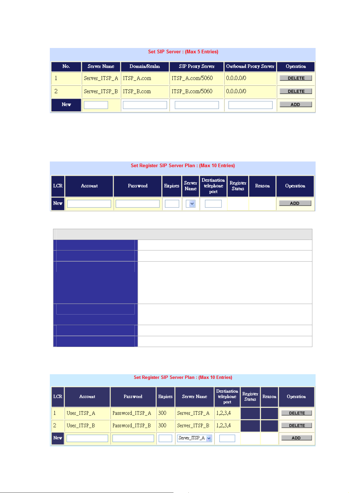
Example: ITSP_A and ITSP_B are configured in this setting.
- Step 2: Configure SIP Account
You can find Set Register SIP Server Plan in Advance Setting – VoIP Basic
Set Register SIP Server Plan
Account
Password
Expires
Input SIP account(Username)
Input Password that ITSP support.
This field sets how long an entry remains registered with the SIP
register server. The register server can use a different time
period. The Gateway sends another registration request after half
of this configured time period has expired.
Server Name
It’s been configured in SET SIP Server, it is used for indicating
this account and password will be applied to which ITSP.
Destination Telephone Port
Account
When SIP account has been reached, which ports answer.
Input SIP account(Username)
Example: Both Accounts are configured in this setting.
50
Page 51

- Step 3: Configure Least Cost Route
You can find LCR Outgoing Dial Rule in Advance Setting – Dialing Plan
LCR Outgoing Dial Rule
Outgoing Number
Length Min
Length Maxi
Delete Length
It’s is the leading digits of the call out dialing number
Min allowed length you can dial.
MAX allowed length you can dial.
the number of digits that will be stripped from beginning of the
dialed number.
Add Digits
LCR Idxs
is the digits that will be added to the beginning of the dialed number.
It’s shown in Set Register SIP Server Plan, it is used for indicating
the rule should be applied to which ITSP.
As we know that make international calls, we should dial International Prefix Code + Country Code +
Telephone Number.
In our case, calling to U.S.A(+1), we should apply the setting with ITSP_A.
The number is like 00 + 1 + x (wildcard)
The setting above means when dialing 001x….the call will use the Route LCR IDX 1
Calling to China(+86), we should apply the setting with ITSP_B.
The number is like 00 + 86 + x (wildcard)
The setting above means when dialing 0086x….the call will go though the Route LCR IDX 2
51
Page 52

According the rules, the gateway can achieve the goal: Least Cost Route by making calls through
relatively cheaper ITSP providers.
Port Status
Port Status Display: This selection will display concurrent call status of this gateway. The status
information of each voice channel includes codec, dialing number and destination IP address. The
status is refreshed every 3 seconds.
52
Page 53

Management
Save Configuration
Chapter 5
5
System Administrations
Management Label
You can save configuration and restart the gateway with the default
configuration or with the current running configuration.
Access Control
Set to Default
Backup/Restore
Configuration
System Information
SNTP Setting
Syslog Setting
Capture Packets
Users can sets/changes the administrator password...
You can restart the VIP-GW with the default configuration.
User can backup the configuration file of VPI-GW to PC or restore
the configuration file from PC.
Display software version, WAN Type, VoIP status, VoIP codec, and
phone interface and system information.
SNTP (Simple Network Time Protocol) configuration for
synchronizing gateway clocks in the global Internet.
VIP-GW can send log information to Syslog Server by UDP ports
514.
The VIP-GW supports packets capture and save the packets to
your PC.
Page 54

Save Configuration
This page allows you to click “Save Configuration and Reboot” to save configuration and begin to
restart.
Access Control
Changing the Administrator/Guest Password
For security reasons, we strongly recommend that you set an administrator/password for the router. On
first setup the router requires no password. If you don’t set a password the router is open and can be
logged into and settings changed by any user from the local network or the Internet.
Click Access Control Setup, the following screen will open.
Administrator username/password: admin/123
Guest username/password: guest/guest
Set To Default Configuration
If you want to reboot the router using factory default configuration, click “Apply” then reset the
router’ s settings to default values.
54
Page 55
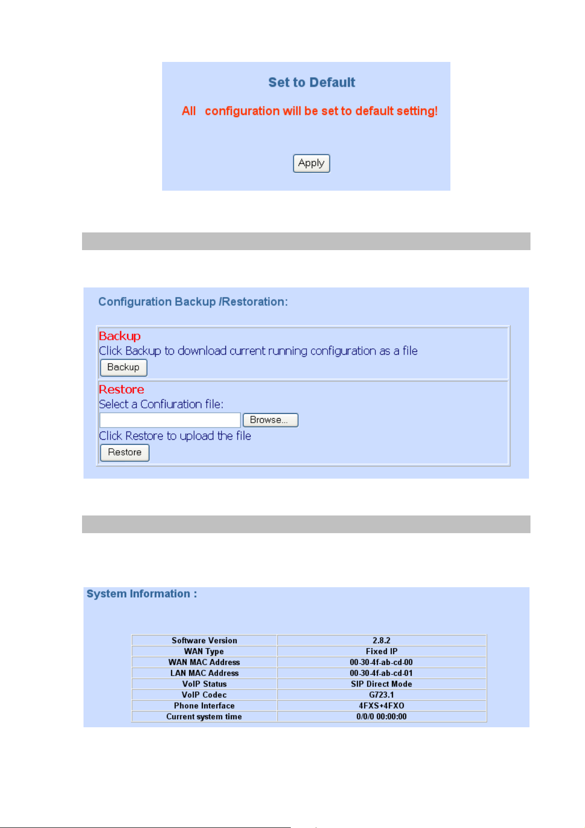
Backup/Restore Configuration to a File
User can backup the configuration to a File at Microsoft Operation System. And also restore the
configuration file to the VIP-GW from PC.
System Information Display Function
Click System Information Display to open the Online Status page. In the example, on the foll
owing page, both PPPoE connections is up on the WAN interface, H323/SIP Status, MAC addr
ess, Register Status.., etc.
55
Page 56

SNTP Setting Function
Click SNTP setting to open the Online Status page. In the example, on the following page:
Use SNTP Setting— when checked, gateway uses a Simple Network Time Protocol (SNTP) to set the
date and time. The gateway synchronizes the gateway’s time after you select the time zone. Use SNTP
Setting; select the time zone which gateway was at.
Syslog setting
Use Syslog server to record your VIP-GW log file. To set the Syslog server IP address for this function.
Kindly please download for this FREE service at http://www.kiwisyslog.com/index.php
understandings.
for more
56
Page 57

Capture packetackets Function
Use “Capturer Packets” to record VIP-GW packets. Users can start and stop the capture then save the
file to PC. Use the Ethereal Tool (www.ethereal.com
) to analyze the packets.
57
Page 58

Appendix A
Voice communications
The chapter shows you the concept and command to help you configure your PLANET VIP-GW
through sample configuration. And provide several ways to make calls to desired destination in VIP-GW.
In this section, we’ll lead you step by step to establish your first voice communication via web browsers
operations.
Concepts: Voice port
There are two type of the voice port, FXO (Foreign exchange Office) and FXS. (Foreign exchange
Station) On the printing of the RJ-11 port, you should find that.
FXO (Foreign exchange Office) port
The FXO port allows the connection with a device that already has a fixed number; say 222, or
412-1111. So the only connections for FXO port will be to your local PSTN or one of your extension-line
from your PBX system.
With your FXO connect to PSTN; the Internet Voice can then have a local call through this line/number
(412-1111). Or, locally, you can have an Internet Call through the line 412-1111
The same to PBX system, you are required to know with which extension number to the FXO port. Your
PBX users will need to know this number in the future.
*
Hint
FXO port cannot connect to an end-node like telephone or fax machine (since
they do not provide a number!). If you connect those to FXO port, you will hear
nothing once you pick up the handset.
FXO
222
412-1111
58
Page 59

FXS (Foreign exchange Station) port
The FXS port allows the connection to an end node, like telephone, fax machine, or out-line of PBX
system.
FXS port is as like your local phone service provider who provides a number to you. It is easy to tell that
after you have connected an end-device to FXS port and you will hear the dial-tone from FXS port once
the hand set off-hook.
Caution
0
FXS
222
412-1111
The FXS port is with voltage and current. DO NOT connects the port to any
PBX extension line or PSTN line. This may make the FXS port or your PBX
extension port malfunction.
59
Page 60
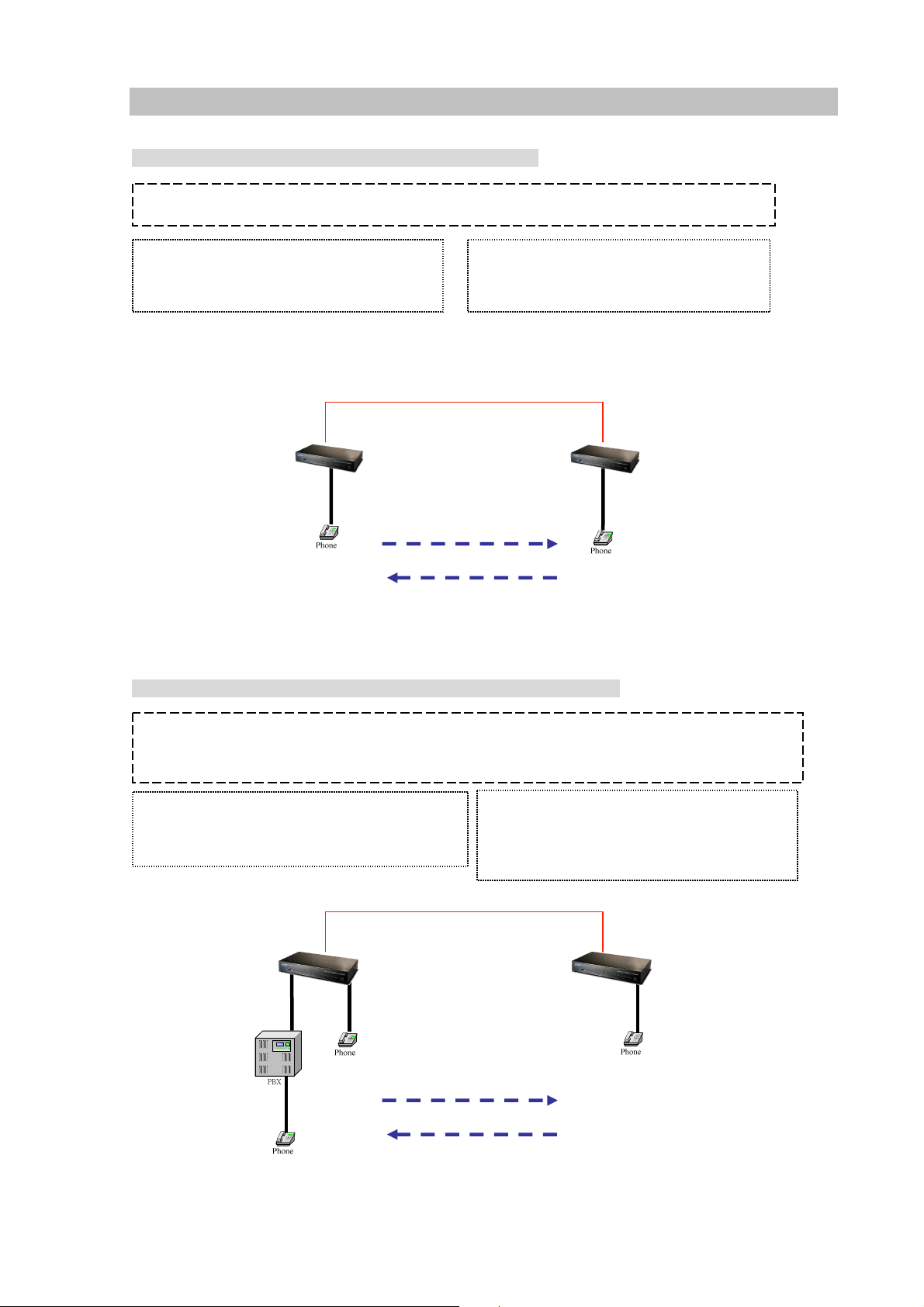
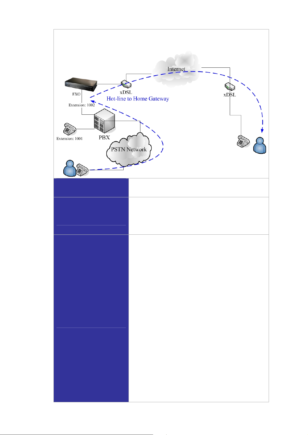
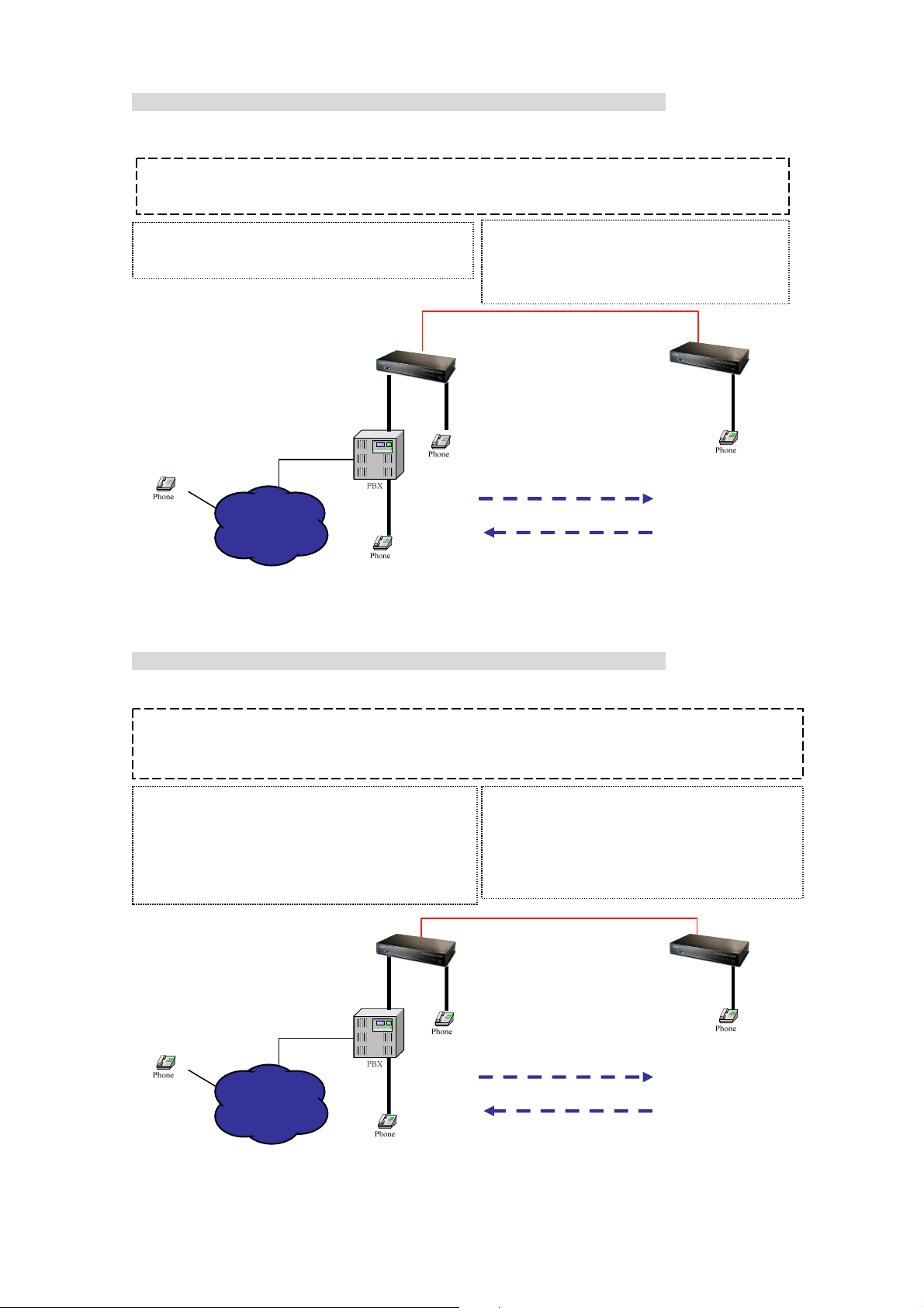
H.323 VoIP Call: Peer-To-Peer Mode
Scenario 1: Gateway 1 to Gateway 2 PLAR connection
H.323 Call (Peer-To-Peer Mode)
Outgoing Dial plan
No: 8x | Digit: 3~3 |Des: GW2 IP address
x: wild card
Des: Destination IP
Digit: Digit Length min~ max
Gateway#1
901
Outgoing Dial plan
No: 9x | Digit: 3~3 | Des: GW1 IP address
WA N
Gateway#2
801
901
Scenario 2: Gateway 1 (with PBX) to Gateway 2 PLAR connection
801
H.323 Call (Peer-To-Peer Mode) with PBX: Call PBX Extension
Method 1: Two-Stage-Dialing
Outgoing Dial plan
No: 8x | Digit: 3~3 | Des: GW2 IP address
x: wild card
Des: Destination IP
Gateway#1
Extension 609
901
Outgoing Dial plan
No: 9x | Digit: 3~3 | Des: GW1 IP address
No: 6x | Digit: 3~3 | Des: GW1 IP address
WA N
Gateway#2
801
Extension 601
609, 601
801
60
Page 61
Scenario 3: Gateway 1 (with PBX/PSTN) to Gateway 2 PLAR connection
|
|
|
g
Call Method: Two-Stages-Dialing
H.323 Call (Peer-To-Peer Mode) with PBX: Remote Call PSTN number
Method 1: Two-Sta
Outgoing Dial plan
No: 8x
X: wild card
Des: Destination IP
Digit: Digit Length min~ max
02-12345678
Digit:3~3 | Des: GW2 IP address
Trunk-Line
es-Dialing
Extension 609
PSTN
Gateway
901
Extension 601
Outgoing Dial plan
No: 9x | Digit: 3~3 | Des: GW1 IP address
No: 6x
#1
Digit:3~3 | Des :GW1 IP address
WA N
Gateway
#2
801
801
609, 0, 12345678
Scenario 4: Gateway 1 (with PBX/PSTN) to Gateway 2 PLAR connection
Call Method: One-Shot-Dialing
H.323 Call (Peer-To-Peer Mode) with PBX: Remote Call PSTN number
Method 2: One-Shot-Dialing
Outgoing Dial plan
No: 8x | Digit: 3~3 |Des:GW2 IP address
Incoming Dial Plan
No: 02x| Digit:3~10 |Strip:2 |Prefix: 0,,,|FXO port
x: wild card
Des: Destination IP
Extension 609
02-12345678
Trunk-Line
Outgoing Dial plan
No: 9x | Digit: 3~3 | Des: GW1 IP address
No: 6x | Digit: 3~3 | Des: GW1 IP address
No: 02x
Digit: 3~10 | Des: GW 1 IP address
WA N
Gateway
901
#1
Gateway#2
801
801
Extension 601
02-12345678
61
Page 62

Scenario 5: Gateway 2 to Gateway 1 (Remote Call PSTN number) PLAR connection
g
g
g
Call Method: One-Shot-Dialing
H.323 Call (Peer-To-Peer Mode) : Remote Call PSTN number
Method: One-Shot-Dialin
Outgoing Dial plan
No: 8x | Digit: 3~3, Des | GW2 IP address
Incoming Dial Plan
No: 02x | Digit: 3~10 |Strip:2 | FXO port
x: wild card
Des: Destination IP
Di
it: Digit Length min~ max
02-12345678
FXO
Outgoing Dial plan
No: 9x | Digit: 3~3 | Des: GW1 IP address
No: 6x | Digit: 3~3 | Des: GW1 IP address
No: 02x| Digit: 3~10 | Des: GW 1 IP address
Gateway
901
WA N
#1
Gateway#2
801
02-12345678
Scenario 6: Gateway 2 to Gateway 1 (Remote Call PSTN number) PLAR connection
801
Call Method: One-Shot-Dialing
H.323 Call (Peer-To-Peer Mode) : PSTN Call PSTN number
Method: One-Shot-Dialin
Outgoing Dial plan
No: 8x | Digit: 3~3 | Des: GW2 IP address
No: 04x | Digit: 3~10 | Des: GW2 IP address
Incoming Dial Plan
No: 02x | Digit: 3~10 |Strip:2 | FXO port
x: wild card
Des: Destination IP
02-87654321
FXO
Outgoing Dial plan
No: 9x | Digit: 3~3 | Des: GW1 IP address
No: 6x | Digit: 3~3 | Des: GW1 IP address
No: 02x| Digit: 3~10 | Des: GW 1 IP address
Incoming Dial Plan
No: 04x | Digit: 3~10 | Strip:2 | FXO port
Gateway#1
901
WA N
04-12341234
Gateway#2
04-56785678
FXO
801
02-12345678
56785678, 02-12345678
04-12341234
62
Page 63

H.323 VoIP Call: Gatekeeper Mode
y
K
Scenario 7: Gateway 1 to Gateway 2 PLAR connection
H.323 Call (GK Mode)
Register Number List
GW1: 801
GW2: 901
GK
WAN
Gateway#1
Gateway#2
801
901
801
901
Scenario 8: Gateway 2 to Gateway 1 (Call PBX extension number) PLAR connection
Call Method: Two-Stages-Dialing
H.323 Call (GK Mode) with PBX: Call PBX Extension
Method 1: Two-Stage-Dialing
Register Number List
GW1: 801
GW2: 901,609
G
x: wild card
Gateway#1
WA N
Gatewa
#2
Extension 609
801
901
801
Extension 601
609, 601
63
Page 64
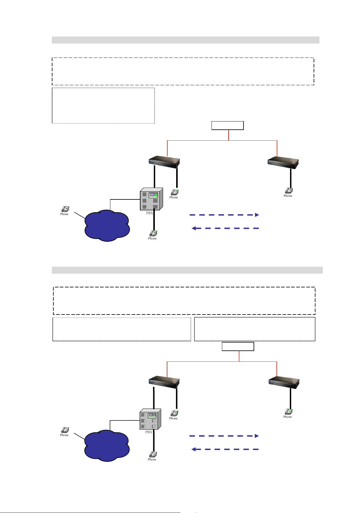
Scenario 9: Gateway 2 to Gateway 1 (Remote Call PSTN number with PBX) PLAR connection
Call Method: Two-Stages-Dialing
H.323 Call (GK Mode) with PBX: Remote Call PSTN number
Method 1: Two-Stages-Dialing
Register Number List
GW1: 801
GW2: 901,609
GK
Gateway#2
801
02-12345678
Extension 609
Trunk-Line
Gateway#1
901
WA N
801
Extension 601
609, 0, 23221344
Scenario 10: Gateway 2 to Gateway 1 (Remote Call PSTN number with PBX) PLAR connection
Call Method: One-Shot-Dialing
H.323 Call (GK Mode) with PBX: Remote Call PSTN number
Method 2: One-Shot-Dialing
Incoming Dial Plan
No: 02x | Digit: 3~10 |Strip:2 |Prefix: 0, | FXO port
x: wild card
Des: Destination IP
Digit: Digit Length min~ max
Extension
Trunk-Line
02-12345678
Gateway#1 Gateway#2
Extension 601
Register Number List
GW1: 801, GW2: 901,609,02x
GK
WA N
901
801
02-12345678
801
64
Page 65

Scenario 11: Gateway 2 to Gateway 1 (Remote Call PSTN number) PLAR connection
y
g
g
g
,
Call Method: One-Shot-Dialing
H.323 Call (GK Mode) : Remote Call PSTN number
Method: One-Shot-Dialing
Incoming Dial Plan
No: 02x | Digit: 3~10 | Strip:2 | FXO port
x: wild card
Des: Destination IP
Di
it: Digit Length min~ max
FXO
02-12345678
Register Number List
GW1: 801, GW2: 901,609,02x
Gateway#1
901
WA N
801
GK
Gatewa
#2
02-12345678
Scenario 12: Gateway 2 to Gateway 1 (Remote Call PSTN number) PLAR connection
Call Method: One-Shot-Dialing
801
H.323 Call (GK Mode) : PSTN Call PSTN number
Method: One-Shot-Dialin
Register Number List
GW1: 801
Incoming Dial Plan
No: 02x | Digit: 3~10 | Strip:2 | FXO port
x: wild card
Des: Destination IP
Di
it: Digit Length min~ max
GW2: 901,609,02x, 04 xs
02-87654321
FXO
Incoming Dial Plan
No: 04x | Digit: 3~10 | Strip:2 | FXO port
Gateway#1 Gateway#2
901
87654321, 04-12341234
02-12345678
56785678, 02-12345678
GK
WA N
04-56785678
FXO
801
04-12341234
65
Page 66

SIP VoIP Call: Peer-To-Peer Mode
y
|
Scenario 13: Gateway 1 to Gateway 2 PLAR connection
SIP Call (Peer-To-Peer Mode)
Outgoing Dial plan
No: 8x | Digit: 3~3, Des | GW1 IP address
x: wild card
Des: Destination IP
Digit: Digit Length min~ max
Gateway#1
Outgoing Dial plan
No: 9x | Digit: 3~3, Des | GW1 IP address
WA N
Gateway#2
801
901
801
901
Scenario 14: Gateway 2 to Gateway 1 (Call PBX extension number) PLAR connection
Call Method: Two-Stages-Dialing
SIP Call (Peer-To-Peer Mode) with PBX: Call PBX Extension
Method 1: Two-Stage-Dialing
Outgoing Dial plan
No: 8x | Digit: 3~3 |Des GW2 IP address
x: wild card
Des: Destination IP
Gateway#1
Extension 609
901
Outgoing Dial plan
No: 9x | Digit: 3~3 |Des: GW1 IP address
No: 6x
WA N
Digit: 3~3 |Des: GW1 IP address
Gatewa
801
Extension 601
609, 601
#2
801
66
Page 67

Scenario 15: Gateway 2 to Gateway 1 (Remote Call PSTN number with PBX) PLAR connection
g
|
|
Call Method: Two-Stages-Dialing
SIP Call (Peer-To-Peer Mode) with PBX: Remote Call PSTN number
Method 1: Two-Stages-Dialing
Outgoing Dial plan
No: 8x | Digit: 3~3, Des | GW2 IP address
x: wild card
Des: Destination IP
Digit: Digit Length min~ max
Extension 609
Trunk-Line
02-12345678
Gateway#1
Outgoing Dial plan
No: 9x | Digit: 3~3, Des | GW1 IP address
No: 6x
901
Digit: 3~3, Des | GW1 IP address
WA N
Gateway#2
801
801
Extension 601
Scenario 16: Gateway 2 to Gateway 1 (Remote Call PSTN number with PBX) PLAR connection
609, 0, 12345678
Call Method: One-Shot-Dialing
SIP Call (Peer-To-Peer Mode) with PBX: Remote Call PSTN number
Method 2: One-Shot-Dialing
Outgoing Dial plan
No: 8x | Digit: 3~3, Des | GW2 IP address
Incoming Dial Plan
No:02x | Digit: 3~10 |Strip:2|Prefix:0,,,| FXO port
x: wild card
Des: Destination IP
Di
it: Digit Length min~ max
02-12345678
Trunk-Line
Extension 609
Gateway#1 Gateway#2
Outgoing Dial plan
No: 9x | Digit: 3~3 | Des: GW1 IP address
No: 6x | Digit: 3~3 | Des: GW1 IP address
No: 02x
Digit: 3~10 | Des: GW 1 IP address
WA N
901
801
801
Extension 601
02-12345678
67
Page 68

Scenario 17: Gateway 2 to Gateway 1 (Remote Call PSTN number) PLAR connection
Call Method: One-Shot-Dialing
SIP Call (Peer-To-Peer Mode) : Remote Call PSTN number
Method: One-Shot-Dialing
Outgoing Dial plan
No: 8x | Digit: 3~3, Des | GW2 IP address
Incoming Dial Plan
No: 02x | Digit: 3~10 | Strip:2 | FXO port
x: wild card
Des: Destination IP
FXO
02-12345678
Gateway#1 Gateway#2
Outgoing Dial plan
No: 9x | Digit: 3~3 | Des: GW1 IP address
No: 6x | Digit: 3~3 | Des: GW1 IP address
No: 02x| Digit: 3~10 | Des: GW 1 IP address
WA N
901
801
02-12345678
Scenario 18: Gateway 2 to Gateway 1 (PSTN Call PSTN number) PLAR connection
Call Method: One-Shot-Dialing
801
SIP Call (Peer-To-Peer Mode) : PSTN Call PSTN number
Method: One-Shot-Dialing
Outgoing Dial plan
No: 8x | Digit: 3~3, Des | GW2 IP address
No: 04x| Digit: 3~10 | Des: GW2 IP address
Incoming Dial Plan
No: 02x | Digit:3~10 | Strip :2 | FXO port
x: wild card
Des: Destination IP
02-87654321
FXO
02-12345678
Outgoing Dial plan
No: 9x | Digit: 3~3 | Des: GW1 IP address
No: 6x | Digit: 3~3 | Des: GW1 IP address
No: 02x| Digit: 3~10 | Des: GW 1 IP address
Incoming Dial Plan
No: 04x | Digit: 3~10 | Strip:2 | FXO port
Gateway#1 Gateway#2
901
WA N
04-12341234
56785678, 02-12345678
04-12341234
04-56785678
FXO
801
68
Page 69

SIP VoIP Call: SIP Proxy Server
y
Scenario 19: Gateway 1 to Gateway 2 PLAR connection
SIP Call (Register to SIP Proxy Server Mode)
Register Number List
GW1: 801
GW2: 901
SIP Proxy Server
WA N
901
Gateway#1
Gatewa
801
#2
801
901
Scenario 20: Gateway 2 to Gateway 1 (Call PBX extension number) PLAR connection
Call Method: Two-Stages-Dialing
SIP Call (SIP Proxy Server Mode) with PBX: Call PBX Extension
Method 1: Two-Stage-Dialing
Register Number List
GW1: 801
GW2: 901,609
Extension 609
Extension 601
SIP Proxy Server
Gateway#1 Gateway#2
WA N
901
801
609, 601
801
69
Page 70
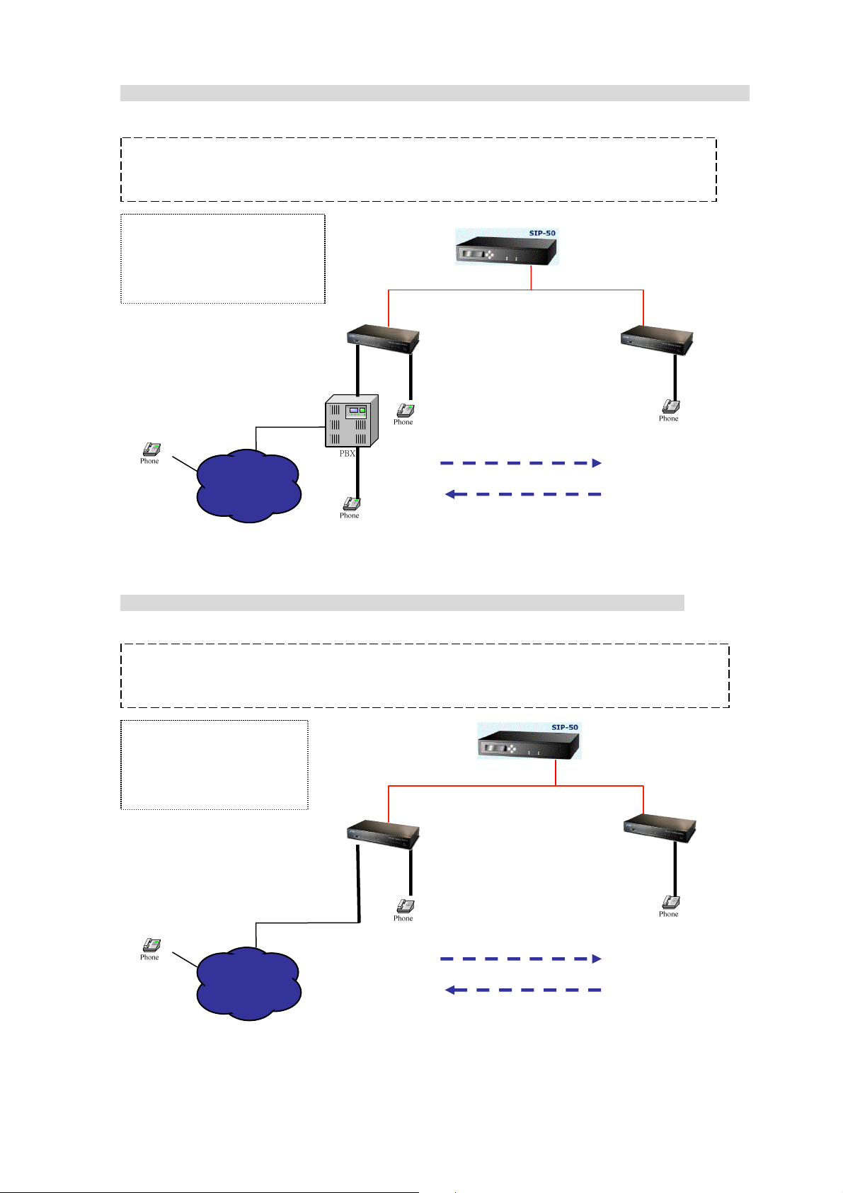
Scenario 21: Gateway 2 to Gateway 1 (Remote Call PSTN number with PBX) PLAR connection
Call Method: Two-Stages-Dialing
SIP Call (SIP Proxy Server Mode) with PBX: Remote Call PSTN number
Method: Two-Stages-Dialing
Register Number List
GW1: 801
GW2: 901,609
Trunk-Line
Extension 609
Gateway#1 Gateway#2
901
WA N
SIP Proxy Server
801
02-12345678
Extension 601
Scenario 22: Gateway 2 to Gateway 1 (Remote Call PSTN number) PLAR connection
Call Method: Two-Stages-Dialing
SIP Call (SIP Proxy Server Mode) : Remote Call PSTN number
609, 0, 12345678
801
Method: Two-Stages-Dialing
Register Number List
GW1: 801
GW2: 901,904
-
904
FXO
Gateway#1
901
WA N
Gateway#2
801
904, 12345678
SIP Proxy Server
801
70
Page 71

Scenario 23: Gateway 2 to Gateway 1 (PSTN Call PSTN number) PLAR connection
Call Method: Two-Stages-Dialing
SIP Call (SIP Proxy Server Mode) : PSTN Call PSTN number
Method: Two-Stages-Dialing
Register Number List
GW1: 801,804
GW2: 901,904
SIP Proxy Server
02-12345678
904
FXO
02-87654321
Gateway#1 Gateway#2
901
WA N
804
FXO
04-56785678
87654321, 804,
56785678,904, 12345678
04-43221344
801
71
Page 72

Appendix B
FAQ
Q: What is the default administrator password to login to the gateway?
A: By default, your default username is “admin”; default password is “123” to login to the
router. For security, you should modify the password to protect your gateway against hacker
attacks.
Note: Default guest login username/password: guest/guest
Q: I forgot the administrator password. What should I do?
A: Press the Reset button on the rear panel for over 5 seconds to reset all settings to default
values.
Q: What is the default IP address of the router?
A: The default WAN IP address is 172.16.0.1 with subnet mask 255.255.0.0.
The default LAN IP address is 192.168.0.1 with subnet mask 255.255.255.0.
Q: Why is it that I can ping to outside hosts, but not access Internet
Web sites?
A: Check the DNS server settings on your PC. You should get the DNS servers settings
from your ISP. If your PC is running a DHCP client, remove any DNS IP address setting. As
the router will assign the DNS settings to the DHCP-client-enabled PC.
Q: 5. What is the maximum number of IP addresses that the DHCP server of the
gateway can assign to local PCs?
A: The built-in DHCP server can support 253 IP addresses for local network usage.
72
Page 73

FAQ 1: Firmware upgrade Requirement and Process
1. Environment Requirement
a) A PC with FTP Server (Server-U software)
b) A PC or Notebook witch connected to LAN port of gateway.
c) Put the image (firmware) named “FW-VIP880_vxxx.bin ” at the assigned folder in FTP Server.
For example: “FW-VIP880_v282.bin” is version 2.8.2L
Note: Free FTP server: 172.16.0.101
username: xxxx, password: xxxx
Environment Architecture (Gateway and FTP server are in Internet):
2. Upgrading Process
a) Notebook Telnet VoIP GW -> open DOS mode ->C:> telnet 192.168.0.1 (Default LAN port IP)
b) Please insert login password: 123, and select [4] Upgrade Software
c) Please input IP address of FTP server like as: 172.16.0.101, username: xxxx, passswd: xxxx, and
image name: FW-VIP880_v282.bin
d) Upgrade (y/n): y, then will write the firmware to flash.
e) After writing flash, Please reboot the Gateway.
f) If the new firmware (image) was most different with the previous version, please push the hardware
reset bottom to set to default.
g) If the VoIP Gateway is in remote site, please use WEB configuration to set to default.
73
Page 74

FAQ 2: Busy Tone Learning
STEP 1: Let the FXO port connect to PBX ext.
STEP 2: To dial to the FXO port from PBX another ext.
STEP 3: Hear dial tone, please dial FXS port number. When
FXS port ring, please hang up the phone.
STEP 4: At this moment, hear busy tone and also press “y” to
learning.
74
Page 75

FAQ 3: FXO Ringer Voltage Threshold / Ringer Voltage Filter Setting
VIP-Gateway provides ring detector in FXO device avoiding can not answer and always OFF-HOOK
status. This ring detector provides two functions to meet the various PBX’s extension port:
1. FXO ringer voltage threshold
2. FXO ringer voltage filter
FXO Ringer Voltage Threshold
These three settings enable satisfaction of global ringer threshold requirements:
Low : 15V ± 10%
Medium: 21V ± 10%
High : 45V ± 10%
Thresholds are set so that a signal is guaranteed to not be detected below the minimum, and a ringer
signal is guaranteed to be detected above the maximum.
FXO Ringer Voltage Filter
Some vendor’s PBX generates the leakage voltage from extension port.
That will mislead the FXO become Off-hook status.
This function was set to avoiding a leakage voltage signal is detected as ring coming.
FAQ 4: Answer Supervision
This chapter document is designed to help explain and resolve issues of answer supervision from a
switch or PSTN provider that could result in billing for termination calls.
VIP-Gateway provides 2 Types of Answer Supervision:
1. Loop-Start Reverse Battery:
Reverse battery (also called Polarity Reverse) is when the PSTN provider reverses the polarity of the
battery voltage, for both answer supervision and disconnects supervision.
75
Page 76
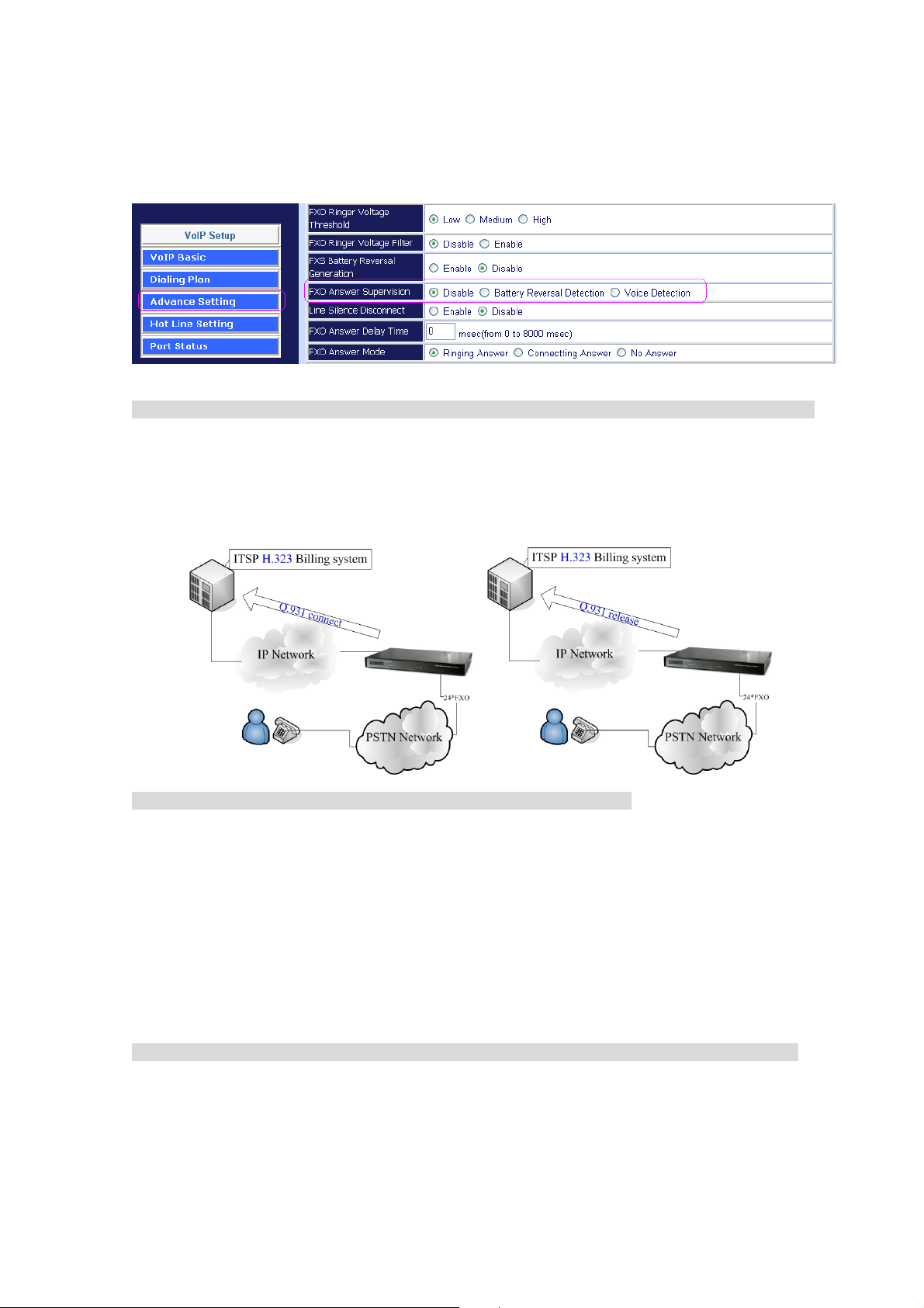
2. Voice Detection:
Voice Detection-based answer supervision is a feature where the Gateway can be configured to “listen”
on the line for different tones and voice. The Gateway sends a “connect” signals out or “disconnect”
signaling using internet.
H.323 scenario description: Loop Start Reverse Battery Æ PSTN line was set polarity reverse
a) The gateway can send the “Q.931 connect” H.323 signals to Billing System of ITSP, after the user
pick up the Phone and detect the PSTN line answer voltage.
b) The gateway can send the “Q.931 Release” H.323 signals to Billing System of ITSP, after the user
hang up the Phone and detect PSTN line disconnect voltage.
Scenario description: Voice Detection based on answer supervision
PSTN Line was not support Polarity Reverse:
a) The gateway can send the Q.931 connect H.323 signals to Billing System of ITSP, after the user pick
up the Phone and detect the voice.
b) The gateway can send the Q.931 Release H.323 signals to Billing System of ITSP, after the user
hang up the phone and detect the hang up voice.
c) This type of answer supervision is not 100% accurate. Any voice frequency is detected as connect,
including any intercept or recorded messages.
SIP scenario description: Loop Start Reverse Battery Æ PSTN line was set polarity reverse
a) The gateway can send the “200 OK” SIP signals to Billing System of ITSP, after the user pick up the
Phone and detect the PSTN line answer voltage.
b) The gateway can send the “200 BYE” SIP signals to Billing System of ITSP, after the user hang up
the Phone and detect PSTN line disconnect voltage.
76
Page 77

Scenario description: Voice Detection based on answer supervision
PSTN Line was not support Polarity Reverse:
a) The gateway can send the 200 OK SIP signals to Billing system of ITSP, after the user pick up the
Phone and detect the voice.
b) The gateway can send the 200 BYE SIP signals to Billing system of ITSP, after the user hang up the
phone and detect the hang up voice.
c) This type of answer supervision is not 100% accurate. Any voice frequency is detected as connect,
including any intercept or recorded messages.
FAQ 5: FXO Answer Mode Setting
FXO Answer Mode Concept: When user calls the PSTN line which was connected with the FXO port,
there are three answer modes for user to configure.
Ringing Answer Mode (Default Setting): FXO answer the call once the ring coming from PSTN line.
Connecting Answer Mode:
Scenario A:
“Hot Line Number” was NOT assigned in the FXO port and the FXO answer the call once the rings
come from PSTN line.
Scencario B:
“Hot Line Number” was assigned and the hot line number belongs to remote VoIP device. In this
scenario, the FXO port will not answer (off-hook) the PSTN till the user picks up the call.
Note: This case can avoid charging for the Local PSTN call when the remote VoIP devices still ring.)
Scenario C:
“Hot Line Number” was setting and the hot line number was assigned to another FXS port in same
gateway. FXO port will not answer (off-hook) till the Phone (connected to the FXS port) was picked up
by user. Note: This case can avoid the Local PSTN charge when the FXS port still ring.)
Non Answer Mode: FXO will NOT answer the call in any time.
77
Page 78

Note: Some ITSP only let the FXO for termination function, they do not user use the FXO port for
origination
SIP Call Connecting Answer Mode
Scenario B description:
Hot Line Number” was assigned and the hot line number belongs to SIP device.
a) When the call com from PSTN to FXO, FXO start the Hot line dialing to remote SIP gateway
b) The phone of remote SIP gateway start ring.
c) When the phone was picked up, the remote SIP Gateway sends “SIP 200 OK” signal to FXO port.
d) Once FXO port receives the “SIP 200 OK” signal, FXO port would off-hook to answer the PSTN call.
Scenario C description:
“Hot Line Number” was setting and the hot line number was assigned to another FXS port in same
gateway.
a) When the call com from PSTN to FXO, FXO start the Hot
line dialing to FXS port.
b) The phone start ring.
c) Once the phone was picked up, FXO port would off-hook
to answer the PSTN call.
78
Page 79

H.323 Call Connecting Answer Mode
Scenario B description:
Hot Line Number” was assigned and the hot line number belongs to remote H.323 device.
Note: The remote H.323 device need disable the “Auto Answer”
a) When the call com from PSTN to FXO, FXO start the Hot line dialing to remote H.323 gateway
b) The phone of remote H.323 gateway start ring.
c) When the phone was picked up, the remote H.323 Gateway send “Q.931 connects” signal to FXO
port.
Once FXO port receives the “Q.931 connects” signal, FXO port would off-hook to answer the PSTN
call.
Scenario C description: “Hot Line Number” was setting and the Hot line number was assigned to
another FXS port in same Gateway.
a) When the call com from PSTN to FXO, FXO start the Hot
line dialing to FXS port.
b) The phone start ring.
c) Once the phone was picked up, FXO port would off-hook to
answer the PSTN call.
79
Page 80

FAQ 6: Peer to Peer call: FXO to FXO
Scenario description:
User (500) on site A (VIP-880FO) wishes to have telephone calls to extension (600) on Site B
(VIP-880FO B). User (500) on site B (VIP-880FO B) can connect to ser A in the same way.
IP address of VIP-880FO_A is: 172.16.0.1
VIP-880FO_A number and dial plan setting:
Each port number is 100,200,300,400,500,600,700,800
IP address of VIP-880FO_B is: 172.16.0.2
VIP-880FO_B number and dial plan setting:
Each port number is 100,200,300,400,500,600,700,800
The dial plan of VIP-880FO_A dial plan setting: that means call 0xxx leading number go to IP address
172.16.0.2 gateway (VIP-880FO_B).
80
Page 81
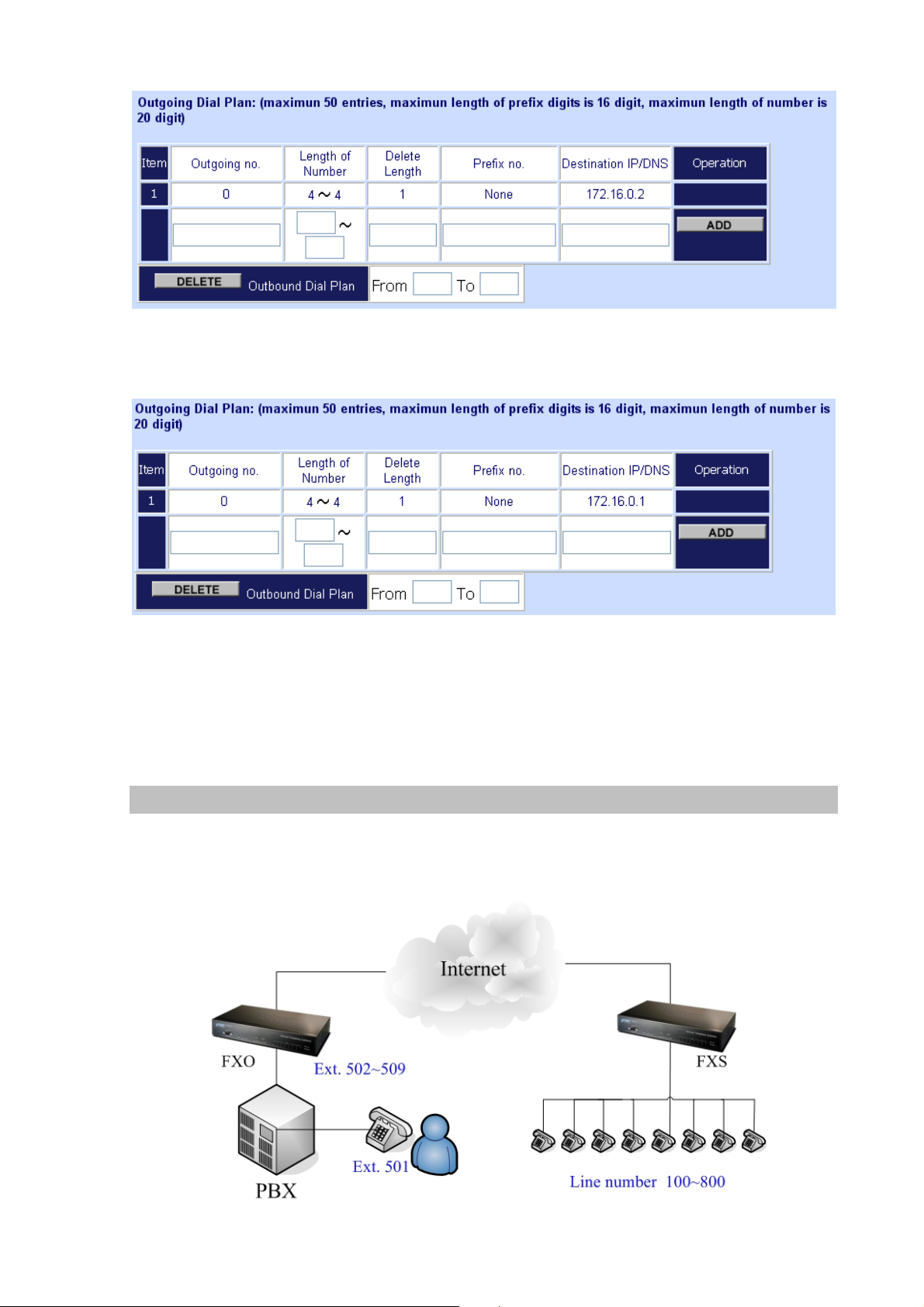
The dial plan of VIP-880FO_B dial plan setting: that means call 0xxx leading number go to IP address
172.16.0.1 gateway (VIP-880FO_A).
Usage:
The ext.509 dial to ext 501 (connect to FXO port 1) will hear the dial tone, and then dial 0100 go to IP
address gateway 172.16.0.2 (VIP-880FO_B), and hear the dial tone again, then dial 609 ext, the
ext.609 will ring.
FAQ 7: Peer to Peer call: FXO to FXS
Scenario description:
User (500) on site A (VIP-880FO) wishes to have telephone calls to phone number (100) on Site B
(VIP-880FS).
81
Page 82

IP address of VIP-880FO is: 172.16.0.1
VIP-880FO number and dial plan setting:
Each port number is 100,200,300,400,500,600,700,800
IP address of VIP-880FS is: 172.16.0.2
VIP-880FS number and dial plan setting:
Each port number is 100,200,300,400,500,600,700,800
The dial plan of VIP-880FO dial plan setting: that means call 0xxx leading number go to IP address
172.16.0.2 gateway (VIP-880FS).
The dial plan of VIP-880FS dial plan setting: that means call 0xxx leading number go to IP address
172.16.0.1 gateway (VIP-880FO).
82
Page 83

Usage:
The ext.509 dial to ext 501 (connect to FXO) will hear the dial tone, and then dial 0100 go to IP address
gateway 172.16.0.2 (VIP-880FS), and phone of port 1(100) will ring.
FAQ 8: Peer to Peer call for one shoot dialing: FXO to FXO
Scenario description:
User (500) on site A (VIP-880FO) wishes to have telephone calls to extension (600) on Site B
(VIP-880FO B). User (500) on site B (VIP-880FO B) can connect to ser A in the sam way.
IP address of VIP-880FO_A is: 172.16.0.1
VIP-880FO_A number and dial plan setting:
Each port number is 100,200,300,400,500,600,700,800
IP address of VIP-880FO_B is: 172.16.0.2
VIP-880FO_B number and dial plan setting:
Each port number is 100,200,300,400,500,600,700,800
VIP-880FO_A Dial Plan setting:
The Incoming Call Dial Plan of VIP-880FO_A: that means incoming call 50x leading number will hunt
port 1 to port 8
83
Page 84

The dial plan of VIP-880FO_A: that means call 0xxx leading number will go to IP address 172.16.0.2
gateway (VIP-880FO_B).
VIP-880FO_B number and dial plan setting:
The dial plan of VIP-880FO_B dial plan setting: that means incoming call 60x leading number will hunt
port 1 to port 8
The dial plan of VIP-880FO_B: That means call 0xxx leading number will go to IP address 172.16.0.1
gateway (VIP-880FO_A).
Usage:
The ext.500 dial to ext 501 (connect to FXO) will hear the dial tone, and then dial 0100 go to IP address
gateway 172.16.0.2, the ext.600 will ring.
84
Page 85

FAQ 9: Peer to Peer call: Hotline setting
Hot line Basic Concept:
Any number set in Hot line field will be dialed by VoIP call automatically.
For FXS port case: When user picks up the phone, the gateway will dial the hot line number to internet
by VoIP call.
For FXO port case: When the FXO off-hook (PSTN call coming or PBX extension ring in), the gateway
will dial the hot line number to internet by VoIP call.
Scenario description: Peer to Peer direct call via SIP or H.323 mode
STEP 1: To set the outgoing call dial plan in gateway, for example the number “911” call to gateway
which’s the IP address is 172.16.0.119.
STEP 2: To set hot line number in Hot Line Setting
STEP 3: When users pick up the phone (port1), the gateway will dial the “911” to the gateway (IP
address: 172.16.0.119)
85
Page 86

Scenario description: Register to SIP proxy server/H.323 Gatekeeper direct call
STEP 1: Let your VIP-GW register to SIP proxy or H.323 Gatekeeper server
STEP 2: To set hot line number in Hot Line Option
STEP 3: When users pick up the phone (port1), the gateway will dial the “911” to SIP proxy or H.323
Gatekeeper server (ITSP)
Scenario description: Register to SIP Proxy / H.323 Gatekeeper server and Peer to Peer direct
call first
STEP 1: Let your VIP-GW register to SIP proxy or H.323 Gatekeeper server
STEP 2: To set the outgoing call dial plan in gateway, for example the “911” will call to gateway which’s
the IP address is 172.16.0.119.
STEP 3: To set hot line number in Hot Line Setting
86
Page 87

STEP 4: When users pick up the phone (port 1), the gateway will dial the “911” to the gateway which’s
IP address 172.16.0.119.
Note: This call will not call to SIP Proxy or H.323 Gatekeeper server because of direct call first.
FAQ 10: SIP speed call setting
Speed calls Concept:
Cut your phone number down to fewer digit dialing!
Life is moving fast - you've got to dial fast. Now you can with Speed Dial. Dial the people you call most
with just dialing fewer digits instead of dialing the full phone number.
What's even better is that you can customize and manage your speed dial phone numbers in Dial Plan
Setting on your gateway! Dial Plan allows you to set up to speed dial numbers that can be called with
the fewer numbers.
Scenario description A: User wants to dial any number instead of 810-any number
Note: The destination IP address is the domain name of SIP proxy server
Scenario description B: User wants to dial 86-1234567890 instead of 810-86-1234567890
Note: The destination IP address is the domain name of SIP proxy server
87
Page 88

Scenario description C: User wants to dial 888 instead of 810-861234567890
Note: The destination IP address is the domain name of sip proxy server
88
Page 89
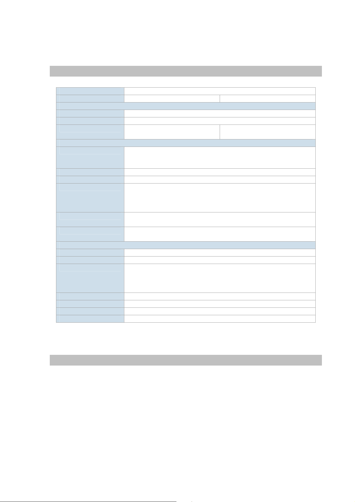
Appendix C
VIP-281 series Specifications
Product 2-Port H.323/SIP VoIP Gateway
Model VIP-281 VIP-281FS
Hardware
WAN 1 x 10/100Mbps RJ-45 port
LAN 4 x 10/100Mbps RJ-45 port
Voice 2 x RJ-11 connection
( 1 x FXS, 1 x FXO)
Protocols and Standard
Standard H.323 v2/v3/v4 and SIP (RFC 3261) , SDP (RFC 2327), Symmetric RTP,
STUN (RFC3489), ENUM (RFC 2916), RTP Payload for DTMF Digits
(RFC2833), Outbound Proxy Support.
Voice codec G.711(A-law /u-law), G.729 AB, G.723 (6.3 Kbps / 5.3Kbps)
Fax support T.30, T.38
Voice Standard Voice activity detection (VAD)
Comfort noise generation (CNG)
G.165/G.168 Echo cancellation
Dynamic Jitter Buffer
Protocols SIP 2.0 (RFC-3261), H.323, TCP/IP, UDP/RTP/RTCP, HTTP, ICMP, ARP,
NAT, DHCP, PPPoE, DNS
Advanced Function Virtual Server, Smart QoS, IP TOS (IP Precedence) / DiffServ, Build-in NAT
router function.
Network and Configuration
Access Mode Static IP, PPPoE, DHCP
Management Web, Telnet
LED Indications System: 1, PWR
WAN: 1, LNK/ACT
LAN: 4, LNK/ACT
Voice 2, In-Use/Ringing
Dimension (W x D x H) 260 x 135 x 35 mm
Operating Environment 0~40 degree C, 0~95% humidity
Power Requirement 12V DC
EMC/EMI CE, FCC Class B
2 x RJ-11 connection
( 2 x FXS)
89
Page 90

VIP-480 series Specifications
Product 4-Port H.323/SIP VoIP Gateway
Model VIP-480 VIP-480FS VIP-480FO VIP-480FD
Hardware
WAN 1 x 10/100Mbps RJ-45 port
LAN 4 x 10/100Mbps RJ-45 port
Voice 4 x RJ-11
connection
( 2 x FXS, 2 x FXO)
Protocols and Standard
Standard H.323 v2/v3/v4 and SIP (RFC 3261) , SDP (RFC 2327), Symmetric RTP,
STUN (RFC3489), ENUM (RFC 2916), RTP Payload for DTMF Digits (RFC2833),
Outbound Proxy Support.
Voice codec G.711(A-law /u-law), G.729 AB, G.723 (6.3 Kbps / 5.3Kbps)
Fax support T.30, T.38
Voice Standard Voice activity detection (VAD)
Comfort noise generation (CNG)
G.165/G.168 Echo cancellation
Dynamic Jitter Buffer
Protocols SIP 2.0 (RFC-3261), H.323, TCP/IP, UDP/RTP/RTCP, HTTP, ICMP, ARP, NAT,
DHCP, PPPoE, DNS
Advanced Function Virtual Server, Smart QoS, IP TOS (IP Precedence) / DiffServ, Build-in NAT router
function.
Network and Configuration
Access Mode Static IP, PPPoE, DHCP
Management Web, Telnet
LED Indications System: 1, PWR
WAN: 1, LNK/ACT
LAN: 4, LNK/ACT
Voice 4, In-Use/Ringing
Dimension (W x D x H) 260 x 135 x 35 mm
Operating Environment 0~40 degree C, 0~95% humidity
Power Requirement 12V DC
EMC/EMI CE, FCC Class B
4 x RJ-11
connection
( 4 x FXS)
4 x RJ-11
connection
( 4 x FXO)
4 x RJ-11
connection
( 4 x FXO with
Caller ID)
90
Page 91

VIP-880 series Specifications
Product 8-Port H.323/SIP VoIP Gateway
Model VIP-880 VIP-880FO
Hardware
WAN 1 x 10/100Mbps RJ-45 port
LAN 1 x 10/100Mbps RJ-45 port
Voice 8 x RJ-11 connection
( 4 x FXS, 4 x FXO)
Protocols and Standard
Standard
Voice codec G.711(A-law /μ-law), G.729 AB, G.723 (6.3 Kbps / 5.3Kbps)
Fax support T.30, T.38
Voice Standard Voice activity detection (VAD)
Protocols SIP 2.0 (RFC-3261), H.323, TCP/IP, UDP/RTP/RTCP, HTTP, ICMP, ARP, NAT,
Advanced Function Virtual Server, Smart QoS, IP TOS (IP Precedence) / DiffServ, Build-in NAT router
Network and Configuration
Access Mode Static IP, PPPoE, DHCP
Management Web, RS-232 Console, Telnet
LED Indications System: 2, PWR, CPU
Dimension (W x D x H) 300 x 160 x 40 mm
Operating Environment 0~40 degree C, 0~95% humidity
Power Requirement 12V DC
EMC/EMI CE, FCC Class B
H.323 v2/v3/v4 and SIP (RFC 3261) , SDP (RFC 2327), Symmetric RTP,
STUN (RFC3489), ENUM (RFC 2916), RTP Payload for DTMF Digits (RFC2833),
Outbound Proxy Support.
Comfort noise generation (CNG)
G.165/G.168 Echo cancellation
Dynamic Jitter Buffer
DHCP, PPPoE, DNS
function.
WAN: 2, LNK/ACT
LAN: 2, LNK/ACT
Voice 8, In-Use/Ringing
8 x RJ-11 connection
( 8 x FXO)
91
Page 92

VIP-1680 series Specifications
Product 16-Port H.323/SIP VoIP Gateway
Model VIP-1680 VIP-1680FS VIP-1680FO VIP-1680FD
Hardware
WAN 1 x 10/100Mbps RJ-45 port
LAN 1 x 10/100Mbps RJ-45 port
Voice 1 x RJ-21
connector for
connecting to
telephone patch
panel
(8 x FXS, 8 x
FXO)
Protocols and Standard
Standard H.323 v2/v3/v4 and SIP (RFC 3261) , SDP (RFC 2327), Symmetric RTP,
STUN (RFC3489), ENUM (RFC 2916), RTP Payload for DTMF Digits (RFC2833),
Outbound Proxy Support.
Voice codec G.711(A-law /u-law), G.729 AB, G.723 (6.3 Kbps / 5.3Kbps)
Fax support T.30, T.38
Voice Standard Voice activity detection (VAD)
Comfort noise generation (CNG)
G.165/G.168 Echo cancellation
Dynamic Jitter Buffer
Protocols TCP/IP, UDP/RTP/RTCP, HTTP, ICMP, ARP, NAT, DHCP, PPPoE, DNS
Advanced Function Virtual Server, Smart QoS, IP TOS (IP Precedence) / DiffServ, Build-in NAT router
function.
Network and Configuration
Access Mode Static IP, PPPoE, DHCP
Management Web, Telnet, Console
LED Indications System: 2, PWR/CPU
WAN: 2, LNK/ACT
LAN: 2, LNK/ACT
Voice 16, In-Use/Ringing
Dimension (W x D x H) 440 x 250 x 44 mm
Operating Environment 0~40 degree C, 0~95% humidity
Power Requirement 100~240V AC 50/60Hz
EMC/EMI CE, FCC Class B
1 x RJ-21
connector for
connecting to
telephone patch
panel
(16 x FXS)
1 x RJ-21
connector for
connecting to
telephone patch
panel
(16 x FXO)
16 x RJ-11
connection
( 16 x FXO with
Caller ID)
92
Page 93

VIP-2480 series Specifications
Product 24-Port H.323/SIP VoIP Gateway
Model VIP-2480 VIP-2480FS VIP-2480FO VIP-2480FD
Hardware
WAN 1 x 10/100Mbps RJ-45 port
LAN 1 x 10/100Mbps RJ-45 port
Voice 1 x RJ-21
connector for
connecting to
telephone patch
panel
(12 x FXS, 12 x
FXO)
Protocols and Standard
Standard H.323 v2/v3/v4 and SIP (RFC 3261) , SDP (RFC 2327), Symmetric RTP,
STUN (RFC3489), ENUM (RFC 2916), RTP Payload for DTMF Digits (RFC2833),
Outbound Proxy Support.
Voice codec G.711(A-law /u-law), G.729 AB, G.723 (6.3 Kbps / 5.3Kbps)
Fax support T.30, T.38
Voice Standard Voice activity detection (VAD)
Comfort noise generation (CNG)
G.165/G.168 Echo cancellation
Dynamic Jitter Buffer
Protocols TCP/IP, UDP/RTP/RTCP, HTTP, ICMP, ARP, NAT, DHCP, PPPoE, DNS
Advanced Function Virtual Server, Smart QoS, IP TOS (IP Precedence) / DiffServ, Build-in NAT router
function.
Network and Configuration
Access Mode Static IP, PPPoE, DHCP
Management Web, Telnet, Console
LED Indications System: 2, PWR/CPU
WAN: 2, LNK/ACT
LAN: 2, LNK/ACT
Voice 24, In-Use/Ringing
Dimension (W x D x H) 440 x 250 x 44 mm
Operating Environment 0~40 degree C, 0~95% humidity
Power Requirement 100~240V AC 50/60Hz
EMC/EMI CE, FCC Class B
1 x RJ-21
connector for
connecting to
telephone patch
panel
(24 x FXS)
1 x RJ-21
connector for
connecting to
telephone patch
panel
(24 x FXO)
24 x RJ-11
connection
( 24 x FXO with
Caller ID)
93
 Loading...