

Page 1
Wireless Analog Telephone Adapter
VIP-161W / VIP161SW
User’s manual
Version 1.0.0
1
Page 2

Copyright
Copyright (C) 2007 PLANET Technology Corp. All rights reserved.
The products and programs described in this User’s Manual are licensed products of PLANET Technology, This
User’s Manual contains proprietary information protected by copyright, and this User’s Manual and all
accompanying hardware, software, and documentation are copyrighted.
No part of this User’s Manual may be copied, photocopied, reproduced, translated, or reduced to any electronic
medium or machine-readable form by any means by electronic or mechanical. Including photocopying, recording,
or information storage and retrieval systems, for any purpose other than the purchaser's personal use, and without
the prior express written permission of PLANET Technology.
Disclaimer
PLANET Technology does not warrant that the hardware will work properly in all environments and applications,
and makes no warranty and representation, either implied or expressed, with respect to the quality, performance,
merchantability, or fitness for a particular purpose.
PLANET has made every effort to ensure that this User’s Manual is accurate; PLANET disclaims liability for any
inaccuracies or omissions that may have occurred.
Information in this User’s Manual is subject to change without notice and does not represent a commitment on the
part of PLANET. PLANET assumes no responsibility for any inaccuracies that may be contained in this User’s
Manual. PLANET makes no commitment to update or keep current the information in this User’s Manual, and
reserves the right to make improvements to this User’s Manual and/or to the products described in this User’s
Manual, at any time without notice.
If you find information in this manual that is incorrect, misleading, or incomplete, we would appreciate your
comments and suggestions.
CE mark Warning
The is a class B device, In a domestic environment, this product may cause radio interference, in which case the
user may be required to take adequate measures.
WEEE Warning
To avoid the potential effects on the environment and human health as a result of the presence of
hazardous substances in electrical and electronic equipment, end users of electrical and electronic
equipment should understand the meaning of the crossed-out wheeled bin symbol. Do not dispose of
WEEE as unsorted municipal waste and have to collect such WEEE separately.
Trademarks
The PLANET logo is a trademark of PLANET Technology. This documentation may refer to numerous hardware
and software products by their trade names. In most, if not all cases, their respective companies claim these
designations as trademarks or registered trademarks.
2
Page 3

Revision
User’s Manual for PLANET Wireless Analog Telephone Adapter:
Model: WATA
Rev: 1.0.0 (2007, August)
Part No. EM-VIP_WATAV1
3
Page 4

TABLE OF CONTENTS
Chapter 1..................................................................................................................................7
Overview............................................................................................................................................7
Package Content.............................................................................................................................8
Physical Details...............................................................................................................................9
LED Display..........................................................................................................................................................10
Chapter 2................................................................................................................................11
Physical Installation Requirement............................................................................................11
Hardware Installation........................................................................................................................................11
Port Description..................................................................................................................................................11
Installation............................................................................................................................................................12
Wizard Setup........................................................................................................................................................13
Operation Mode..................................................................................................................................................13
Internet Setting Setup ......................................................................................................................................15
NAT setting ...........................................................................................................................................................17
VoIP Call Setup....................................................................................................................................................18
Chapter 3................................................................................................................................19
Configuring Netowrk setting for your Wi-Fi ATA..................................................................19
WAN Setting / LAN Setting .............................................................................................................................19
Static IP..................................................................................................................................................................20
DHCP (Dynamic Host Configuration Protocol).......................................................................................20
PPPoE (Point-to-Point Protocol over Ethernet).....................................................................................20
Host Name.............................................................................................................................................................21
WAN Port MAC....................................................................................................................................................21
MTU and MRU......................................................................................................................................................21
DNS Server...........................................................................................................................................................22
Ping From WAN...................................................................................................................................................22
LAN Setting ..........................................................................................................................................................22
DNS Proxy.............................................................................................................................................................22
WLAN Setting......................................................................................................................................................23
WLAN Settings....................................................................................................................................................23
AP Mode.................................................................................................................................................................23
Access Policy (For AP and AP& AP-Client mode only).......................................................................29
DHCP Server Setting.........................................................................................................................................30
Static Router........................................................................................................................................................31
NAT (for AP / AP-Client / WISP & AP mode).............................................................................................33
NA T Setting...........................................................................................................................................................33
4
Page 5

Virtual Server setting (for AP mode)...........................................................................................................34
Port Trigger...........................................................................................................................................................35
Packet Filter .........................................................................................................................................................36
URL Filter...............................................................................................................................................................37
Security (For AP / WISP & AP mode)..........................................................................................................38
UPNP (For AP / WISP & AP mode)...............................................................................................................39
DDNS (For AP / WISP & AP mode)...............................................................................................................40
SNMP (For AP / WISP & AP mode)...............................................................................................................41
QoS (VLAN) ..........................................................................................................................................................42
Chapter 4................................................................................................................................43
SIP Configuration..........................................................................................................................43
Basic Setting........................................................................................................................................................43
Account Setting..................................................................................................................................................45
Server Setting......................................................................................................................................................46
NAT Traversal ......................................................................................................................................................48
VoIP Setting....................................................................................................................................48
Voice Setting........................................................................................................................................................48
CODEC ...................................................................................................................................................................48
Echo Canceller....................................................................................................................................................49
Gain Control Level.............................................................................................................................................49
DTMF Method.......................................................................................................................................................50
RTP (Real-time Transport Protocol)............................................................................................................50
Call Service...........................................................................................................................................................51
Call Waiting...........................................................................................................................................................51
Call Transfer Option..........................................................................................................................................52
Call Forward Option..........................................................................................................................................52
FXS Port Setting.................................................................................................................................................53
FAX Setting...........................................................................................................................................................55
General Dialing Setting....................................................................................................................................55
Phone Book..........................................................................................................................................................55
Dialing Plan (Outgoing Mode).......................................................................................................................56
Call Screen............................................................................................................................................................58
QoS Setting ..........................................................................................................................................................58
Information .....................................................................................................................................59
System Information...........................................................................................................................................59
Line Status............................................................................................................................................................61
Management...................................................................................................................................61
Administrator Account.....................................................................................................................................61
5
Page 6

Date/Time...............................................................................................................................................................62
Ping Test................................................................................................................................................................63
Save/Restore........................................................................................................................................................64
Factory Default....................................................................................................................................................64
Firmware Update................................................................................................................................................64
Auto Provision ....................................................................................................................................................65
Check Network Alive.........................................................................................................................................66
Save & Logout.....................................................................................................................................................66
Save Configurations.........................................................................................................................................67
Save Configuration & Logout........................................................................................................................67
Save Configuration & Reboot........................................................................................................................67
Appendix A Voice Communication Samples.........................................................................68
Make a three - way conference call.............................................................................................................70
Appendix B Frequently Asked Questions List......................................................................71
Appendix C VIP-161W/VIP-161SW Specifications................................................................72
6
Page 7

Chapter 1
1
Introduction
Overview
Combining the cutting edge of Internet telephony and ATA manufacturing experience, PLANET now
introduces the latest member of PLANET Wireless ATA family: the VIP-161W/VIP-161SW.
To bring the most satisfaction to customers, the WATA not only provides the high quality of voice
communications and wired Internet sharing capabilities but also offers Access Point (AP) function for
daily wireless communication. With advanced router and VoIP DSP processor technology, the WATA is
able to make calls via SIP proxy voice communications plus the IP sharing and the QoS mechanism.
The WATA is the ideal choice for Voice over IP communication and integrates Internet sharing for the
daily tasks. To give most flexibility to users, the Wireless ATA provides direct analog interface for fax
machine and analog telephones. Users can not only make the daily VoIP communication but also enjoy
the convenience brought by FoIP communications.
With the WATA, home users and companies are able to save the cost of installation and extend their
previous investments in telephones, conferences and speakerphones. The WATA equipped with two
telephony interfaces, so users may register to different SIP proxy servers and establish up to 2
concurrent VoIP calls for more flexibility in the voice communications. The WATA can be the bridge
between traditional analog telephones and IP network with an extremely affordable investment.
The WATA includes two Ethernet interface for Internet (PPPoE, DHCP or Fixed IP) or office LAN
connection. The dual Ethernet design brings the greatest convenience when deploying VoIP network.
With a built-in IEEE 802.11b/g wireless AP/CPE, the Wi-Fi ATA offers wireless connectivity via 54Mbps
data transmissions.
7
Page 8

Product Features
• IEEE 802.11b/g compliant
• Multi-mode: AP, AP-Client Mode
• Smart QoS mechanism to ensure the voice quality
• Auto-config feature for flexible, ease-of use system integration
• NAT Router, Static Routing, Virtual Server, DMZ
• Smart QoS mechanism to ensure the voice quality
• IP ToS (IP Precedence) / DiffServ
VoIP Featires
• SIP 2.0 (RFC3261) compliant
• Up to 2 concurrent VoIP calls
• Voice codec support: G.711, G.729 AB, G.723, G.276
• T.38 FAX transmission over IP network (G.711 Fax pass-through)
• In-band and out-of-band DTMF Relay (RFC 2833)
• Three-way conference calls
• Call Waiting / Forward / Transfer / Hold / Resume / Screen
• Caller ID Detection/Generation: DTMF, Bellcore, ETSI, NTT
• Voice processing: VAD, CNG, Dynamic Jitter Buffer, G.168~2000 echo cancellation
Package Content
The contents of your product should contain the following items:
1. Wireless Analog Telephone Adapter
2. Power adapter
3. Dipole Antenna
4. Quick Installation Guide
5. User’s Manual CD
6. RJ-45 cable
8
Page 9
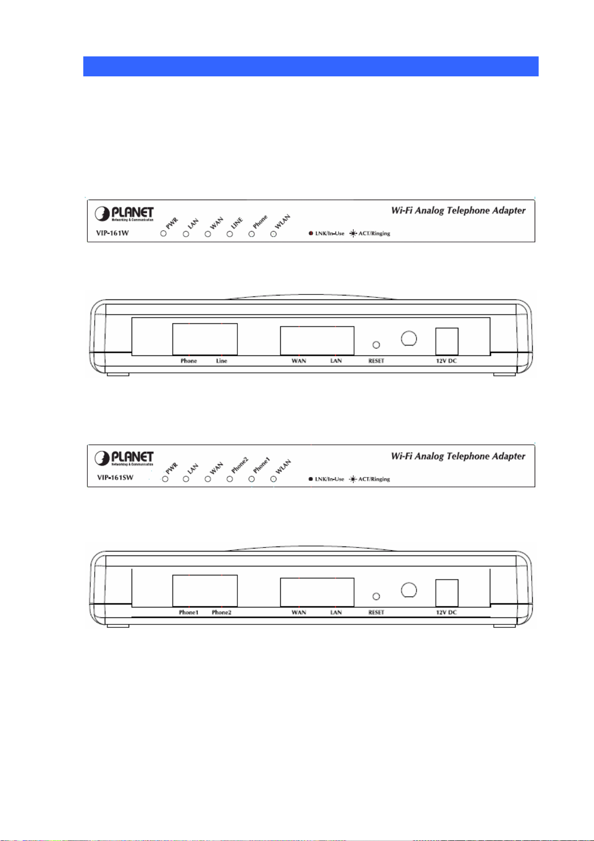
Physical Details
The following figure illustrates the front/rear panel of WATA.
Respective model/descriptions are shown below:
VIP-161W: 1 FXS / 1 PTSN Wireless Analog Telephone Adapter.
VIP-161SW: 2 FXS Wireless Analog Telephone Adapter
Front Panel of VIP-161W
Back Panel of VIP-161W
Front Panel of VIP-161SW
Back Panel of VIP-161SW
9
Page 10

LED Display
LED display of VIP-161W / VIP-161SW
LED Indicators Descriptions
PWR
WAN
LAN
Phone 1 (FXS1)
Phone 2 (FXS2)
Line (VIP-161W only)
WLAN
On: WATA is power ON
Off: WATA is power Off
On: WATA network connection established
Flashing: Data traffic on cable network
Off: Waiting for network connection
On: LAN is connected successfully
Flashing: Data is transmitting
Off: Ethernet not connected to PC
Off: Telephone Set is On-Hook
Flashing: Ring Indication
On: Telephone Set is Off-Hook
OFF: Wireless network connection established.
Flashing: Data traffic on cable network
ON: Waiting for network connection
ÍNote
Press RESET button on rear panel over 5 seconds will reset
the WATA to factory default value
10
Page 11

Chapter 2
A
A
2
Preparations & Installation
Physical Installation Requirement
This chapter illustrates basic installation of Wireless Analog Telephone Adapter (“WATA” in the
following term)
• Network cables. Use standard 10/100BaseT network (UTP) cables with RJ-45 connectors.
• TCP/IP protocol must be installed on all PCs.
For Internet Access, an Internet Access account with an ISP, and either of a DSL or Cable modem
Hardware Installation
Port Description
Connect to the network with an Ethernet cable. This port allows
your W
1 WAN
2 LAN
Phone
3
4 Line
5 Reset
External
6
Antenna Area.
router, cable modem, ADSL modem, through a networking
cable with RJ-45 connectors used on 10BaseT and
100BaseTX networks.
Connect to PC with Ethernet cable. 1 port allows your PC or
Switch/Hub to be connected to the WATA through a
networking cable with RJ-45 connectors used on 10BaseT and
100BaseTX networks.
FXS port can be connected to analog telephone sets or Trunk
Line of PBX.
Line port can be connected to RJ11 PSTN line (VIP-161W
only)
Push this button until 3 seconds, and W
factory default configuration.
Used to Wirelessly Connect to 802.11b/g networks
802.11b: 11/5.5/2 Mbps
802.11g: 54/48/36/24/19/12/6Mbps
TA to be connected to an Internet Access device, e.g.
TA will be set to
7 12V DC
12V DC Power input outlet
11
Page 12
Installation
1 Connect the 12V DC IN to the power outlet with power adaptor.
2 Connect Line to PSTN.
3 Connect Phone to a telephone jack with the RJ-11 analog cable.
Connecting to a PC
1 Connect the Ethernet cable (with RJ-45 connector) to any LAN port.
2 Connect the other end of the Ethernet cable to your PC’s installed network interface card (NIC).
Connecting to an External Ethernet Hub or Switch
1 Connect the Ethernet cable (with RJ-45 connector) to WAN port.
2. Connect the other end of the Ethernet cable to DSL/Cable modem or the external Ethernet hub or
switch.
Administration Interface
PLANET WATA provides GUI (Web based, Graphical User Interface) for machine management and
administration.
Web configuration access
To start WATA web configuration, you must have one of these web browsers installed on computer for
management
• Microsoft Internet Explorer 6.0 or higher with Java support
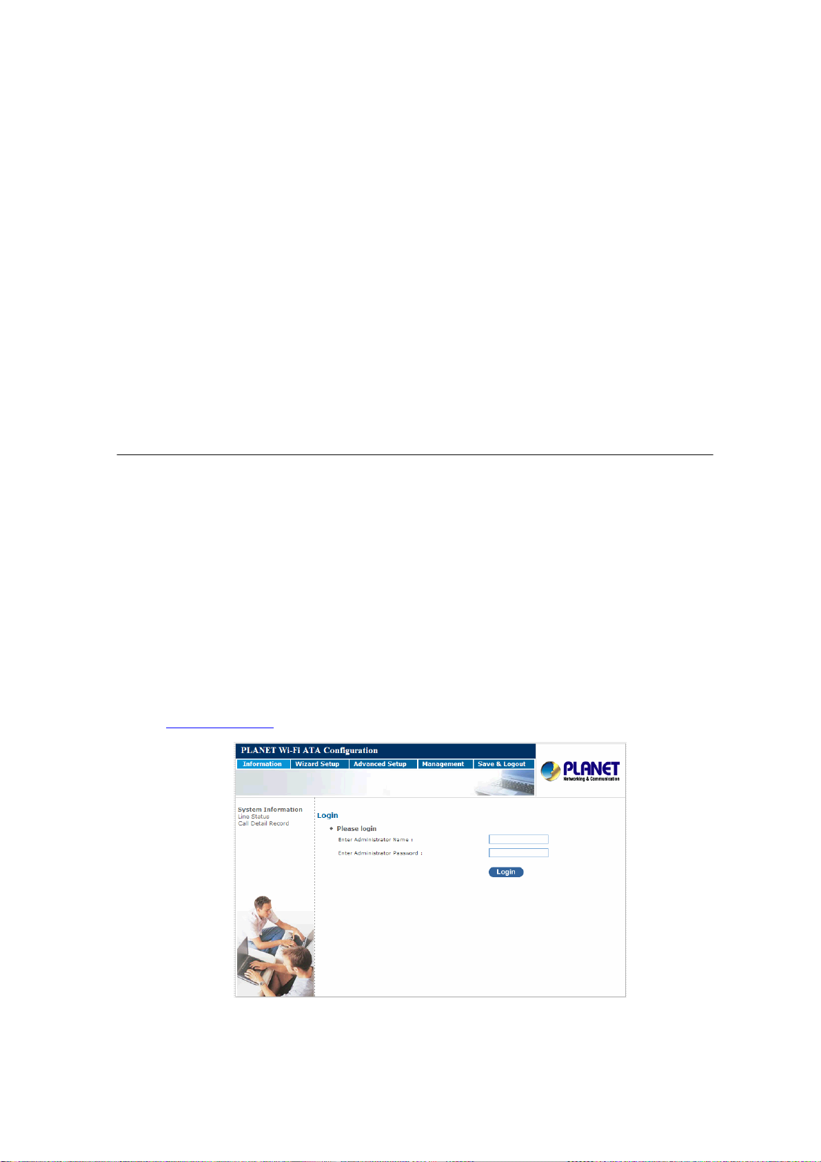
Default LAN interface IP address of WATA is 192.168.0.1. You may now open your web browser, and
insert http://192.168.0.1
in the address bar of web browser to logon WATA web configuration page.
WATA will prompt for logon username/password, please enter: root / null (no password) to continue
machine administration.
12
Page 13

In order to connect machine for administration, please locate
ÍNote
your PC in the same network segment (192.168.0.x) of
VIP-161W/VIP-161SW. If you’re not familiar with TCP/IP,
please refer to related chapter on user’s manual CD or consult
your network administrator for proper network
configurations.
Wizard Setup
Wizard for Quick Setup of the WATA, after finishing the authentication, the Main menu will display 4
parts of configuration, please click “Wizard Setup” to enter quick start: start:
STEP1: Operation Mode STEP1: Operation Mode
a. AP Mode a. AP Mode
b. AP-Client Mode b. AP-Client Mode
c . WISP & AP Mode c . WISP & AP Mode
STEP2: Internet Setting STEP2: Internet Setting
b. AP-Client Only Mode b. AP-Client Only Mode
c. WISP & AP Mode c. WISP & AP Mode
STEP3: NAT Settings STEP3: NAT Settings
a. AP Only Mode a. AP Only Mode
a. Phone Number a. Phone Number
b. SIP Proxy Server IP
STEP4: VOIP Call Setup STEP4: VOIP Call Setup
b. SIP Proxy Server IP
a . Phone Number a . Phone Number
b . SIP Proxy Server IP
b . SIP Proxy Server IP
Operation Mode
For most users, Internet access is the primary application. The WATA supports the WAN or WLAN
interface for Internet access and remote access. When you click “Operation Mode” from within the
Wizard Setup, the following setup page will be show.
13
Page 14
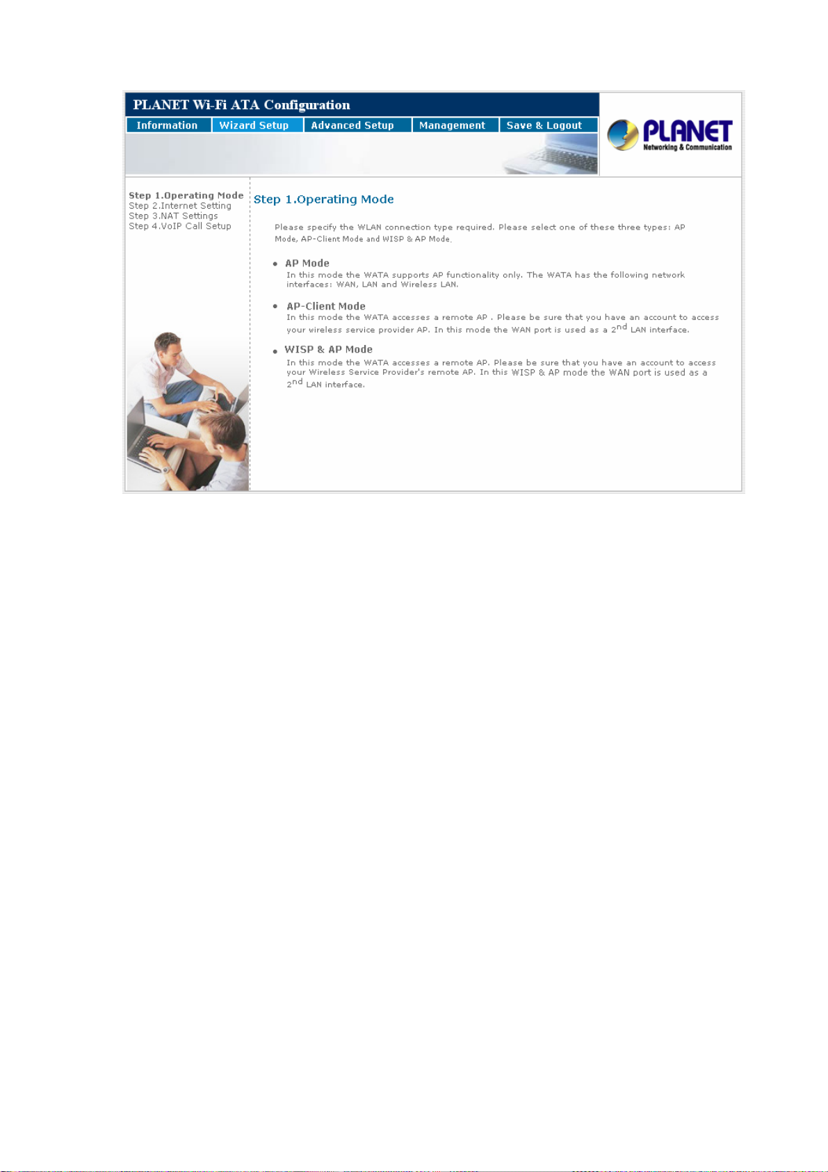
Three WLAN modes of operation are available for Internet Access:
AP Mode:
In this mode the WATA supports AP functionality only. The WATA has the following network
interfaces: WAN, LAN and Wireless LAN.
AP-Client Mode:
In this mode the WATA accesses a remote AP. Please be sure that you have an account to
access your wireless service provider AP. In this mode the WAN port is used as a 2nd LAN
interface.
WISP & AP Mode:
In this mode the WATA accesses a remote AP. Please be sure that you have an account to access
your Wireless Service Provider's remote AP. In this WISP & AP mode the WAN port is used as a 2nd
LAN interface.
14
Page 15
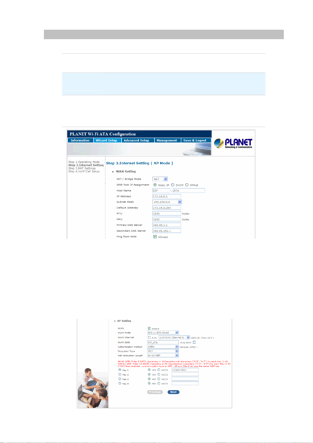
Internet Setting Setup
WAN Setting
NAT Mode
Bridge Mode
WAN Port IP
Assignment
Network Address Translation (NAT) serves connecting multiple
computers to the Internet using one IP address.
Bridge mode serves to connect a local area network (LAN / Wireless)
to another local area network that uses the same protocol.
Three methods are available for Internet Access. Static IP / DHCP /
PPPoE type for your select .you should refer to section 3.1 “WAN
Setting” in user menu.
AP Setting
For configuring correctly the WLAN port in client mode. the below instructions will provide a quick
start. It is advised if possible to use the simplest network settings for first try.
For making sure the WATA is connecting to your wireless router (AP). You need to set up the
following: SSID, Frequency Channel, Authentication method and Encryption parameters
(Type/Encryption length/Keys.)
15
Page 16
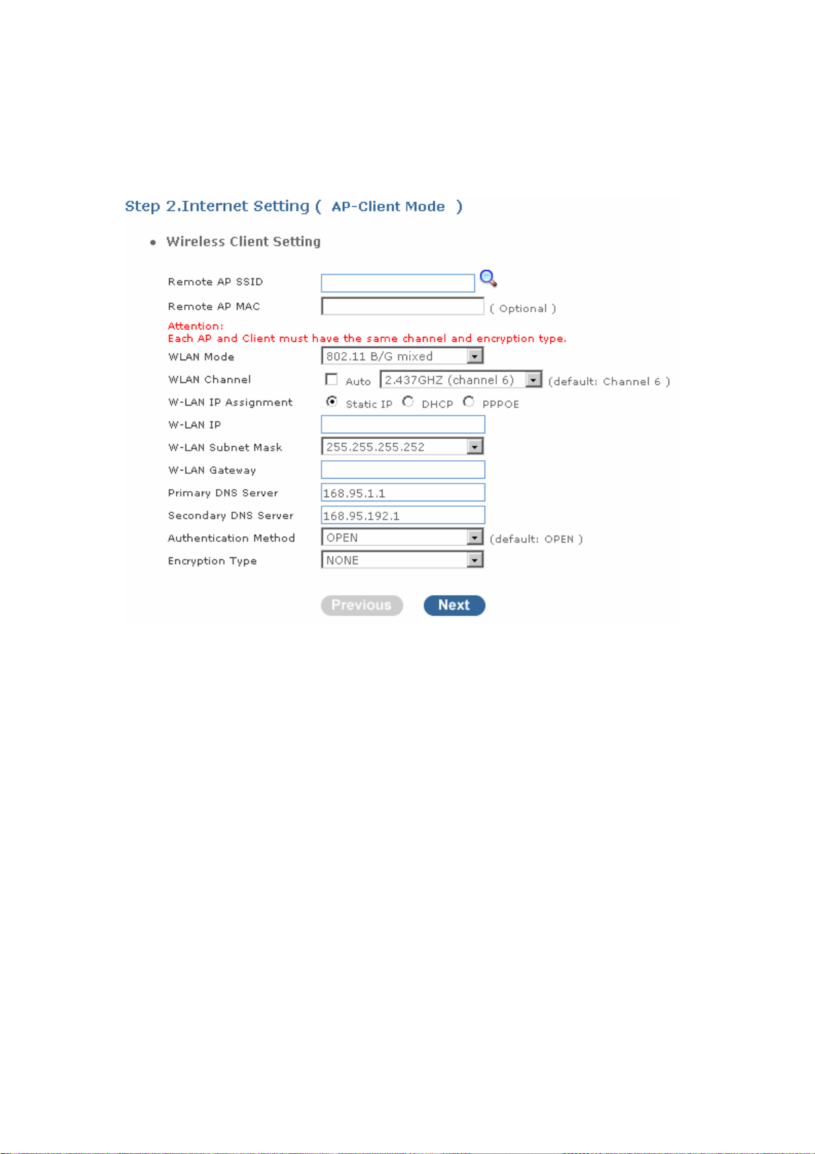
AP-Client Mode
This paragraph defines the required parameters to set up the WLAN interface as a Client on
your wireless access network. You need to define the following parameters:
Default WLAN mode / Remote SSID / Authorization key / IP / Gateway.
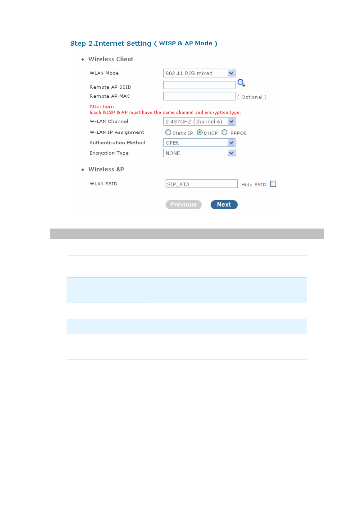
WISP & AP Mode
This paragraph defines the required parameters to set up the WLAN interface as a Client on
your wireless access network. You need to define the following parameters:
Wireless Client
Delault WLAN mode / Remote SSID / Encryption parameters / IP / Gateway
Wireless AP
Local SSID.
16
Page 17
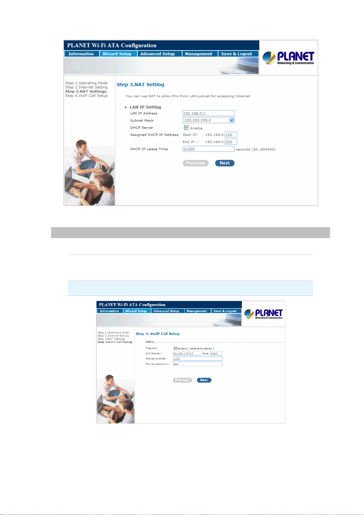
NAT setting
LAN IP Setting
LAN IP Address
Subnet Mask
DHCP Server
Assigned DHCP IP Address
DHCP IP Lease Time
Private IP address for connecting to a local private
network. (Default: 192.168.0.1)
Subnet mask for the local private network (Default:
255.255.255.0)
Enable to open LAN port DHCP server
DHCP server range from start IP to end IP
Client to ask DHCP server refresh time, range from 60 to
86400 seconds
17
Page 18
VoIP Call Setup
Configure the numbering with phone/line ports
SIP Proxy Server IP
addresses
Phone number / password
Finishing the Wizard Setup
There is a SIP Proxy Server address and port fields. Check
with your ITSP provider.
Pleae check with your ISP provider.
After completing the Wizard Setup, please click “Finish” bottom. The WATA will save the configuration
and rebooting WATA automatically. After 30 Seconds, you could re-login the WATA.
18
Page 19

Chapter 3
3
Network Service Configurations
Configuring Netowrk setting for your Wi-Fi ATA
The WATA integrates a web-based graphical user interface that can cover most configurations and
machine status monitoring. Via standard web browser, you can configure and check machine status
from anywhere around the world.
• WAN Setting / LAN Setting
• WLAN
• DHCP Setting
• Static Route (Default Router)
• NAT
• Packet Filter
• URL Filter
• Security
• UPNP
• DDNS
• SNMP
• QOS (VLAN)
WAN Setting / LAN Setting
WAN (Wide Area Network) is a network connection connecting one or more LANs together over some
distance. For example, the means of connecting two office buildings separated by several kilometers
would be referred to as a WAN connection. The size of a WAN and the number of distinct LANs
connected to a WAN is not limited by any definition. Therefore, the Internet may be called a WAN.
WAN Settings are settings that are used to connect to your ISP (Internet Service Provider). The WAN
settings are provided to you by your ISP and often times referred to as "public settings". Please select
the appropriate option for your specific ISP.
For most users, Internet access is the primary application. WATA supports the WAN interface for
internet access and remote access. The following sections will explain more details of WAN Port Internet
access and broadband access setup. When you click “WAN Setting”, the following setup page will be
shown. Three methods are available for Internet Access.
19
Page 20
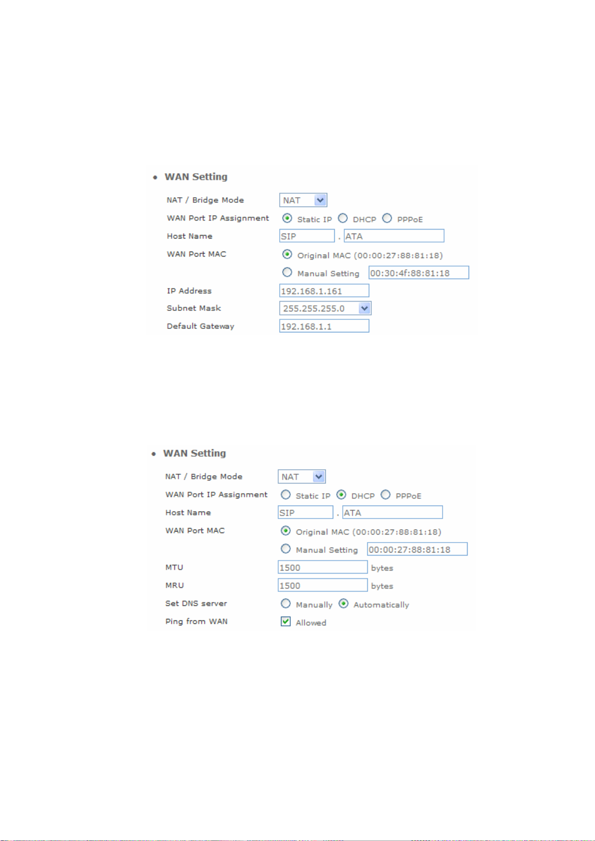
Static IP
If you are a leased line user with a fixed IP address, enter in the IP address, subnet mask, gateway
address, and DNS (domain name server) address(es) provided to you by your ISP. Each IP address
entered in the fields must be in the appropriate IP form, which are four IP octets separated by a dot
(x.x.x.x). The Router will not accept the IP address if it is not in this format.
DHCP (Dynamic Host Configuration Protocol)
Dynamic Host Configuration Protocol (DHCP), Dynamic IP (Get WAN IP Address automatically). If you
are connected to the Internet through a Cable modem line, then a dynamic IP will be assigned.
Note: WAN port gets the IP Address, Subnet Mask and default gateway IP address automatically, if
DHCP client is successful.
PPPoE (Point-to-Point Protocol over Ethernet)
Point-to-Point Protocol over Ethernet (PPPoE). Some ISPs provide DSL-based services and use
PPPoE to establish communication link with end-users. If you are connected to the Internet through a
DSL line, check with your ISP to see if they use PPPoE. If they do, you need to make sure the following
items:
PPPoE User name: Enter username provided by your ISP.
PPPoE Password: Enter password provided by your ISP.
20
Page 21
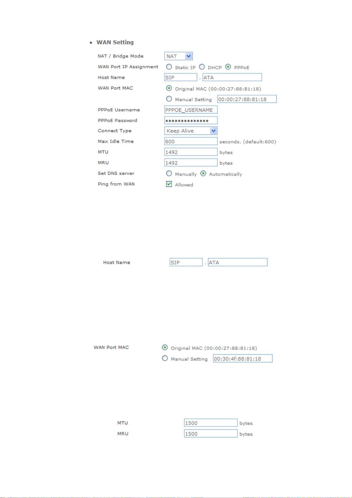
Host Name
The Host Name field is optional but may be required by some Internet Service Providers. The default
host name is the model number of the device. I
WAN Port MAC
The MAC (Media Access Control) Address field is required by some Internet Service Providers (ISP).
The default MAC address is set to the MAC address of the WAN interface in the device. It is only
necessary to fill the field if required by your ISP.
MTU and MRU
MTU stands for Maximum Transmission Unit, the largest physical packet size, measured in bytes that a
network can transmit. Any messages larger than the MTU are divided into smaller packets before being
sent.
21
Page 22
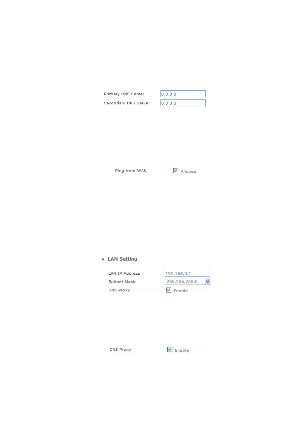
DNS Server
DNS stands for Domain Name System. Every Internet host must have a unique IP address; also they
may have a user-friendly, easy to remember name such as www.wata.com
the user-friendly name into its equivalent IP address.
The original DNS specifications require that each domain name is served by at least 2 DNS servers
for redundancy.
The DNS server converts
Ping From WAN
Ping is a basic Internet program that lets you verify that a particular IP address exists and can accept
requests. Ping is used diagnostically to ensure that a host computer you are trying to reach is actually
operating.
LAN Setting
These are the IP settings of the LAN interface for the device. These settings may be referred to as
"private settings". You may change the LAN IP address if needed. The LAN IP address is private to your
internal network and cannot be seen on the Internet. The default IP address is 192.168.0.1 with a subnet
mask of 255.255.255.0.
LAN is a network of computers or other devices that are in relatively close range of each other.
DNS Proxy
A proxy server is a computer network service that allows clients to make indirect network connections
to other network services. The default setting is Enable the DNS proxy server.
22
Page 23

WLAN Setting
A WLAN is a data communication system that reduces the need for a wired connection, thereby adding
new flexibility and convenience to your network. Using electromagnetic waves, WLAN's transmits and
receives data over the air, minimizing the need for wired connections and combines data connectivity
with user mobility.
WLAN Settings
AP Mode
Access Point only Mode, The AP functions as a wireless hub to which wireless clients can
connect. The clients must make sure that they are configured to match the AP’s wireless settings. The
AP must be connected to switch or other LAN segment patch cable.
WLAN
WLAN Mode
WLAN SSID
Hide SSID
WLAN Frequency
Enable / Disable WLAN Function
For wireless connected type 802.11 B/G mixed / 802.11b only /
802.11G only
Wireless stations associating to the access point must have the
same SSID. Enter a descriptive name for the wireless
LAN.(support 20 ACSII characters)
Hide SSID prevents outside users from joining the network without
knowing the wireless Network's ID, default is check SSID.
The range of radio frequencies used by IEEE 802.11b/g wireless
23
Page 24

devices is called a Selection channel. Select a channel ID that is
not already in use by a neighboring device.
WLAN Frequency
Example:
When the users select this option, the WIFI-ATA automatically
finds the channel with the least interference and uses that channel
Auto
for wireless ATA transmission.
Select OPEN, WPA, WPA-PSK, WPA2, WPA2-PSK, WPA/WPA2
Authentication
mix mode, WPA-PSK/WPA2-PSK mix mode .Default is OPEN
Method
mode.
24
Page 25

AP-Client Only Mode
In this mode the WATA is used to access the Wireless Service Provider network by connecting
wirelessly to the remote (Outdoor AP). The user can access the PSTN network by connecting to the
FXS ports or accessing the internet by connecting the PCs to the 2 Ethernet ports.
ÍNote
WLAN Mode
Remote AP SSID
Remote AP KEY
W-LAN Channel
W-LAN IP Assignment
When WATA operate in AP-Client Mode, the WAN and LAN RJ-45
interface will be configured as a 2 port switch for connecting
with 2 PCs for access wireless network
For wireless connected type 802.11 B/G mixed/ 802.11b only /
802.11G only
Define the same as your Wireless Router uses.
Enter the remote AP Authorization Key (WPA-PSK / WPA2-PSK /
WPAPSK ,WPA2PSK Mix Mode to Show)
Define the same as your Wireless Router uses.
1. DHCP client
2. Static IP Address
25
Page 26

Static IP
Key in the W-LAN IP address, W-LAN Subnet mask and W-LAN
Gateway from AP of WISP
DHCP Client
PPPoE Client
Remote AP SSID
Authentication Method
Encryption Type
When the DHCP Client is enabled, the WIFI ATA will get the IP
Address from Outdoor AP of WISP.
Enter User Name / Password provided by your ISP, the WATA will
get the IP Address from Outdoor AP of WISP
Define the same as your Wireless Router uses
Define the same as your Wireless Router uses.(OPEN / SHARED
Mode)
Define the same as your Wireless Router uses. (OPEN / SHARED
Mode)
Scan usable network:Select list to remote AP SSID (magnifying glass)
Search remote AP list page.
ÍNote
After scan and select the Outdoor AP, the channel and
encryption method should be set the identical with the remote
AP.
26
Page 27

Example:
WISP & AP Mode
The WIFI ATA can operate in AP-Client and access to another (Outdoor) AP. The wireless client needs
to have the same SSID, Channel, Encryption settings as the main AP. The user may need to change
the default IP to avoid IP conflicts.
27
Page 28

ÍNote
W-LAN IP Assignment
When WATA operates in AP-Client (or WISP & AP) Mode, the WAN
and LAN RJ-45 interface will be configured as a 2 port switch
for connecting with 2 PCs for access wireless network.
WLAN Mode
Remote AP SSID
Remote AP MAC
Remote AP Key
W-LAN Channel
For wireless connected type 802.11 B/G mixed/ 802.11b only /
802.11G only
Define the same as your Wireless Router uses
Define the same as your Wireless Router uses
Enter the remote AP Authorization Key (WPA-PSK / WPA2-PSK /
WPAPSK ,WPA2PSK Mix Mode to Show)
Define the same as your Wireless Router uses
1.DHCP client
2.Static IP Address
Static IP
DHCP Client
WLAN SSID
Hide SSID
Authentication Method
Encryption Type
Key in the W-LAN IP address, W-LAN Subnet mask and W-LAN
Gateway from WISP
When the DHCP Client is enabled, the WATA will get the IP Address
from Outdoor AP of WISP
The service set identifier assigned to the wireless network (WLAN).
Default SSID is SIP_ATA
Hide SSID prevents outside users from joining the network without
knowing the wireless Network's ID, default is check SSID
Define the same as your Wireless Router uses. (OPEN / SHARED
Mode)
Define the same as your Wireless Router uses. (OPEN / SHARED
Mode
28
Page 29

ÍNote
Scan usable network:Select list to remote AP SSID (magnifying glass)
Search remote AP list page
After scan and select the Outdoor AP, the channel and
encryption method should be identical with the remote AP
Example:
Access Policy (For AP and AP& AP-Client mode only)
29
Page 30

Access Policy: in WATA security, an access control list is a list of “allow all / Reject all" to an MAC.
Access Control List:MAX MAC List:64.
DHCP Server Setting
DHCP stands for Dynamic Host Control Protocol. The DHCP server gives out IP addresses when a
device is starting up and request an IP address to be logged on to the network. The device must be set
as a DHCP client to "Obtain the IP address automatically". By default, the DHCP Server is enabled in the
unit. The DHCP address pool contains the range of the IP address that will automatically be assigned to
the clients on the network.
An advantage of using DHCP is that the service assigns addresses dynamically. The DHCP Server
returns addresses that are no longer in use to the IP addresses pool so that the server can reallocate
them to other machines in the network. If you disable this DHCP, you would have to manually configure
IP for new computers, keep track of IP addresses so that you could reassign addresses that clients
aren't using, and reconfigure computers that you move from one subnet to another. The DHCP Static
MAP table lists all MAC and IP address which are active now.
When you enable the DHCP server:
30
Page 31

Assigned DHCP IP
Address
DHCP IP Lease Time
Enter the starting IP address for the DHCP server’s IP assignment
and the ending IP address for the DHCP server’s IP assignment.
Assign the length of time for the IP lease, default setting is 86400
seconds.
Static Router
For use when managing local networks. Static routes are special routes that the network administrator
manually enters into the router configuration. You could build an entire network based on static routes.
The problem with doing this is that when a network failure occurs, the static route will not change without
you performing the change. This could be fatal if the failure occurs when the administrator is not
available. The route table allows the user to configure and define all the static routes supported by the
router.
31
Page 32

Enable
Type
Target
NetMask
Gateway
Action
Enable/Disable the static route
Indicates the type of route as follows, Host for local connection and Net
for network connection
Defines the base IP address (Network Number) that will be compared
with the destination IP address (after an AND with NetMask) to see if this
is the target route
The subnet mask that will be AND'd with the destination IP address and
then compared with the Target to see if this is the target route.
The IP address of the next hop router that will be used to route traffic for
this route. If this route is local (defines the locally connected hosts and
Type = Host) then this IP address MUST be the IP address of the router
Insert a new Static Router entry or update a specified entry
32
Page 33

NAT (for AP / AP-Client / WISP & AP mode)
NAT (Network Address Translation) serves three purposes:
• Provides security by hiding internal IP addresses. Acts like firewall.
• Enables a company to access internal IP addresses. Internal IP addresses that are only available
within the company will not conflict with public IP.
• Allows a company to combine multiple ISDN connections into a single internet connection.
NAT Setting
Network Address Translation - Enable/Disable NAT.
IPSec Pass Through:IPsec (Internet Protocol Security) is a framework for a set of protocols for
security at the network or packet processing layer of network communication. Enable/Disable this
framework verification.
PPTP Pass Through:PPTP (Point-to-Point Tunneling Protocol) is a protocol that allows corporations
to extend their own corporate network through private "tunnels" over the public Internet.
Enable/Disable this protocol verification.
L2TP Pass Through:L2TP (The Layer 2 Tunnel Protocol) is an emerging Internet Engineering Task
33
Page 34

Force (IETF) standard that combines the best features of two existing tunneling protocols: Cisco's
Layer 2 Forwarding (L2F) and Microsoft's Point-to-Point Tunneling Protocol (PPTP). L2TP is an
extension to the Point-to-Point Protocol (PPP), which is an important component for VPNs. VPNs allow
users and telecommuters to connect to their corporate intranets or extranets. Enable/Disable this
function.
SIP ALG:SIP, the Session Initiation Protocol, is a signaling protocol for Internet conferencing,
telephony, presence, events notification and instant messaging. Enable/Disable this protocol
verification.
DMZ:In computer networks, a DMZ (Demilitarized Zone) is a computer host or small network inserted
as a "neutral zone" between a company's private network and the outside public network. It prevents
outside users from getting direct access to a server that has company data. Think of DMZ as the front
yard of your house. It belongs to you and you may put some things there, but you would put anything
valuable inside the house where it can be properly secured. Setting up a DMZ is very easy. If you have
multiple computer s, you can choose to simply place one of the computers between the Internet
connection and the firewall.
DMZ LAN IP:If you have a computer that cannot run Internet applications properly from behind the
device, then you can allow the computer to have unrestricted Internet access. Enter the IP address of
that computer as a DMZ host with unrestricted Internet access. Adding a client to the DMZ may expose
that computer to a variety of security risks; so only use this option as a last resort.
Virtual Server setting (for AP mode)
The device can be configured as a virtual server so that remote users accessing services such as Web
or FTP services via the public (WAN) IP address can be automatically redirected to local servers in the
LAN network. Depending on the requested service (TCP/UDP port number), the device redirects the
external service request to the appropriate server within the LAN network. You will only need to input
the LAN IP address of the computer running the service and enable it.
A Virtual Server is defined as a service port, and all requests to this port will be redirected to the
computer specified by the server IP.
34
Page 35

Enable
WAN Port
Protocol
LAN IP
LAN Port
Action
Enable/Disable the virtual server mapping, default setting is Disable.
The port number on the WAN side that will be used to access the
virtual service. Enter the WAN Port number, e.g. enter 80 to represent
the Web (http server), or enter 25 to represent SMTP (email server).
Note: You can specify maximum 32 WAN Ports
The protocol used for the virtual service. Select a protocol type is TCP
or UDP
The server computer in the LAN network that will be providing the
virtual services. Enter the IP address of LAN
The port number of the service used by the Private IP computer. Enter
the LAN port number
Insert a new WAN port or update a specified WAN port
Port Trigger
Some applications require multiple connections, such as Internet gaming, video conferencing,
Internet telephony and others. These applications have difficulties working through NAT (Network
Address Translation). If you need to run applications that require multiple connections, specify the port
normally associated with an application in the "Trigger Port" field, select the protocol type as TCP
(Transmission Control Protocol) or UDP (User Datagram Protocol), then enter the public ports
associated with the trigger port to open them for inbound traffic.
35
Page 36

Enable
Enable / Disable the port trigger, default setting is Disable
Trigger Port
Trigger Type
Public Port
Public Type
Action
Packet Filter
This is the port used to trigger the application. It can be either a single port
or a range of ports
This is the protocol used to trigger the special application
This is the port number on the WAN side that will be used to access the
application. You may define a single port or a range of ports. You can use a
comma to add multiple ports or port ranges.
This is the protocol used for the special application.
Insert a new Port Trigger or update a specified Port Trigger.
Controlling access to a network by analyzing the incoming packets and letting they pass or halting them
based on the IP addresses of the source.
(Can be useful for residential screening as well – for parental screening or other)
36
Page 37

WAN / LAN
The WAN IP port packet filter function, control a network IP port, default
Enable/Disable
Enable
Source IP
Dest. Port
Protocol
Black
Day
Time
setting is Enable
Enable/Disable the Internet to WAN IP source port rules, default setting is
Disabling
This is the filter WAN IP address
This is the port used for source IP service
This Protocol Used for the source IP service. Select a protocol type is TCP
or UDP
Wan IP Port Black time. Select a Always or by schedule
Black day, Select a All / Mon-Sat./ Mon-Fri./Mon./ Tues./
Wed./Thu./Fri./Sat./Sun
Black time, Select time range is 00:00 to 23:59
URL Filter
URL filter allows you to block sites based on a black list and white list. Sites matching the black list but
not matching the white list will be automatically blocked and closed.
37
Page 38

Enable
Enable/Disable the URL filter function, default setting is Disable
Enable
Client IP
URL Filter String
Enable/Disable Block URL to the client IP, default setting is Disable
This is the client IP is LAN address.
This is the filter URL.
Security (For AP / WISP & AP mode)
Intrusion Detection has powerful management and analysis tools that let your IT administrator see
what's going on in your network. Such as who's surfing the Web, and gives you the tools to block
access to inappropriate Web sites. Malicious code (also called vandals) is a new breed of Internet
threat that cannot be efficiently controlled by conventional antivirus software alone. In contrast to
viruses that require a user to execute a program in order to cause damage, vandals are
auto-executable applications.
Intrusion Detection:Enable / Disable the network / Internet security protection.
Drop Malicious Packet:Enable / Disable, Detect and drop malicious application layer traffic.
38
Page 39

UPNP (For AP / WISP & AP mode)
UPnP provides support for communication between control points and devices. The network media, the
TCP/IP protocol suite and HTTP provide basic network connectivity and addressing needed. On top of
these open, standard, Internet based protocols, UPnP defines a set of HTTP servers to handle
discovery, description, control, events, and presentation.
UPNP Internet Gate Device: Enable/Disable UPnP Service to working, default setting is Disable.
39
Page 40

DDNS (For AP / WISP & AP mode)
The DDNS (Dynamic DNS) service allows you to alias a dynamic IP address to a static hostname,
allowing your computer to be more easily accessed from various locations on the Internet. When you
want your internal server to be accessed by using DNS name rather than using the dynamic IP address,
you can use the DDNS service. The DDNS server allows to alias a dynamic IP address to a static
hostname. Unlike DNS that only works with static IP addresses, DDNS works with dynamic IP
addresses, such as those assigned by an ISP or other DHCP server. DDNS is popular with home net
workers, who typically receive dynamic, frequently-changing IP addresses from their service provider.
Enable
DDNS Server Type
DDNS Username
DDNS Password
Confirmed Password
Hostname to register
Enable/Disable the DDNS service, default setting is Disable
The ATA support two types of DDNS, DynDns.org or No-IP.com
The username which you register in DynDns.org or No-IP.com
website
The password which you register in DynDns.org or No-IP.com website
Confirm the password which you typing
The hostname which you register in DynDns.org or No-IP.com
website
40
Page 41

SNMP (For AP / WISP & AP mode)
The simple network management protocol (SNMP) forms part of the internet protocol suite as
defined by the Internet Engineering Task Force (IETF). SNMP is used by network management
systems to monitor network-attached devices for conditions that warrant administrative attention. It
consists of a set of standards for network management, including an Application Layer protocol, a
database schema, and a set of data objects.
Enable
SNMP Read Community
SNMP Write Community
SNMP Trap Host
SNMP Trap Community
Enable/Disable the SNMP service, default setting is Disable
(Support SNMP version 1 or SNMP version 2c)
SNMP Read Community string so that “EPICenter” can retrieve
information.(default :public)
Specifies the name of the SNMP write community to which the printer
device that this actual destination represents belongs.(Default :private)
Defines an SNMP trap host to which “AppCelera” will send trap
messages (Default address is empty)
The SNMP trap community name. The community name functions as a
password for sending trap notifications to the target SNMP manager
(Default:public)
41
Page 42

QoS (VLAN)
VLAN which stands for Virtual LAN is defined in the IEEE802.1q. It is a technology allowing a
company or an individual to extend their LAN over the WAN interface, breaching the physical limitations
of regular LANs.
Enable
Voice VLAN Priority
Voice VLAN ID
Data VLAN Priority
Data VLAN ID
Enable/Disable the QoS service, default setting is Disable
Set voice VLAN Priority 0 -7 ,Default is 1
Voice VLAN ID is entered as an integer , Default is 3 ,value between 0 and
4095
Set Data VLAN Priority 0 -7 ,Default is 0
Data VLAN ID is entered as an integer , Default is 4 ,value between 0 and
4095
42
Page 43

Chapter 4
4
Wireless Telephone Adapter Configurations
SIP Configuration
SIP is a request-response protocol, dealing with requests from clients and responses from servers.
Participants are identified by SIP URLs. Requests can be sent through any transport protocol. SIP
determines the end system to be used for the session, the communication media and media parameters,
and the called party's desire to engage in the communication. Once these are assured, SIP establishes
call parameters at either end of the communication, and handles call transfer and termination.
• Basic Setting
• Account Setting
• Server Setting
• NAT Traversal
Basic Setting
This page defines the SIP and RTP port number in this page. Each ISP provider will have different
SIP/RTPport setting, please refer to the ISP to setup the port number correctly. When you finished the
setting, please click the Submit button.
43
Page 44

SIP Port Number
Session Timer
Media Port Start
Media Port End
RTCP Port
Assign the SIP port number of Telephone adapter. Its range is 1024 to
65535, default setting is 5060
SIP session refresh time interval. The time interval in which the phone
periodically refresh SIP sessions by sending repeated INVITE or Update
request, depending on session type. Its range is 1 to 65535, default setting
is 1800 seconds
The starting range of port for RTP. Port number for initial of sending RTP
packet. Its range is 1024 to 65535, default setting is 5000
The ending range of port for RTP. Its range is 1024 to 65535, default
setting is 5050
The Real Time Transport Control Protocol is based on the periodic
transmission of control packets to all participants in the session, using the
same distribution mechanism as the data packets. The underlying
protocol must provide multiplexing of the data and control packets. Its
range is 1024 to 65535, default setting is 5060
Transport
Assigns the default SIP transport protocol
Offering instead a direct way to send and receive datagram over an IP
UDP
network. It's used primarily for broadcasting messages over a network.
Here the UDP is a default setting
44
Page 45

TCP
TCP guarantees delivery of data and also guarantees that packets will be
delivered in the same order in which they were sent
SIP Time Interval
Timeout for Invite
Timeout for Ring Back
Timeout for Release
Registration Retry count
SIP time interval in milliseconds. The default setting is 500 m-sec
INVITE message timeout value. Assigns a value 1 to 100, default setting
is 12 seconds. It denotes if an INVITE request was sent, and a response
is not received from the remote site within the allotted time. The present
request will be dropped and a new connection request will be initiated
Timeout value for dropping a call after receiving 180 responses. Ring
back is an intermittent audio tone that a caller in a telephone system
hears after dialing a number, when the distant end of the circuit is
receiving a ringing signal. It can be generated by the servicing switch of
either the called party or the calling party. It is not generated by the called
instrument. The default setting is 180 seconds
BYE message timeout value. Assigns a time interval 1 to 4, default setting
is 4 seconds
Assigns a value 1 to 65535, To set the retry count for keepalive
retransmission, use the retry keepalive command in SIP user agent
configuration mode. To restore the retry count to the default value for
keepalive retransmission, use the no form of this command
If specified, is the user-agent name to be used in a REGISTER request. If
SIP User Agent name
not specified, the value in “SIP User Agent Name” will be used for
REGISTER request also. Default value is VOIP_Agent_001
Account Setting
There are two ports can be setup for SIP account.
Assigns Phone number for the first port, maximum 15 digits. Do not contain
Phone Number
Display Name
Authentication User Name
any special characters or spaces. E.g. if you want to enter the number
+886 2 1234-5678, then it should be 886212345678
This text message will be sent between the callee and caller and will show
on LCD panel for general using
User name for authentication. Maximum 36 characters
Authentication Password
User password for authentication. Maximum 24 characters
45
Page 46

Confirmed Password
Enter the password again, this is used to confirm user password for
authentication. Maximum 24 characters
Enable/Disable, Support for the Remote-Party-ID header and
P-Asserted-Identity header—The present SIP implementation always
P-Asserted
Asserted Identity URI
Asserted Identity Display
name
derives the calling party number from the user name field of From header.
But if P-Asserted-Identity header or Remote-Party-ID header is present in
an incoming SIP INVITE message the user name should be derived from
those headers
Enter your URI (Uniform Resource Identifier), Maximum 24 characters
Enter your Display name, Maximum 24 characters
Server Setting
In Server Setting you need to input the SIP Server related informations in this page, please refer to your
ISP provider.
46
Page 47

Authentication Expired
Time
Use Outbound Proxy for
All Messages
Registrar Server Address
Registrar Server Port
Use Outbound Proxy for
Session
Outbound Proxy Address
Outbound Proxy Port
SIP registration expired time. Assigns the time interval from 1 - 65535,
default setting is 3600 seconds
Enable/Disable this flag for out-bound (out-session and in-session)
requests. Default setting is Disable
Assigns the SIP Register Server’s IP address
Port number of SIP Register Server. Assigns a value from 1024 to 65535,
default setting is 5060
Enable/Disable this flag for proxy-outbound, default setting is Disable
Outbound Proxy server’s IP address. Assigns the server’s IP which is in
charge of call-out service
Port number of Outbound Proxy Server. Assigns a number from 1024 to
65535, default setting is 5060
DNS SRV support
Enable / Disable DNS SRV support function, you’ll need DNS server if you
want to use email server. To use it you should check direct delivery on the
addresses tab. DNS server is used to give a route to recipients’ mailbox.
You can use any DNS you know. But the best choice for the fastest
sending is to use your ISP’s DNS
47
Page 48

NAT Traversal
STUN is a protocol for assisting devices behind a NAT firewall or router with their packet routing.
STUN enables a device to find out its public IP address and the type of NAT service its sitting behind.
When you enable the STUN function, you must input the STUN server address.
UPnP: Enable/Disable Universal Plug and Play, default setting is Disable.
VoIP Setting
This page defines the Voice, Call service, FXS / FAX, General Dialing, URI Phone Book, Call Screen,
QoS Setting. You need to follow the ISP suggestion to setup these items. When you finished the setting,
please click the Submit button.
Voice Setting
CODEC
A CODEC is an algorithm for taking voice or video and compressing the information. This type of codec
combines analog-to-digital conversion and digital-to-analog conversion functions in a single chip. The
Codec is used to compress the voice signal into data packets. Each Codec has different bandwidth
requirement. There are 9 kinds of codec, G.711/Ulaw, G.711/Alaw, G.729, G.723, G.726 (16K bps),
G.726 (24K bps), G.726 (32K bps), G.726 (40K bps), and iLBC.
48
Page 49

The Codec is used to compress the voice signal into data packets. Each
Codec Priority 1~9
G.723 Rate
ILBC Mode
Packet Length
Voice Active Detector
It is used in speech encoding software to determine if the voice being encoded is human speech or
background noise. There are three type of silence suppression: NO CNG, Only G.711 Annex II type, and
Codec Specific CN.
Codec has different bandwidth requirement. There are 9 kinds of codec. To
determine the priority, selects one codec algorithm from the pull-down
menus individually
This defines the encoding rate for G723 Codec, default is 6.3Kbps Rate
RTP Payload length. Select a length from the pull-down menu, default
setting is 30 m-sec
RTP payload length. Selects a length from the pull-down menu, default
setting is 20 m-sec
Echo Canceller
The echo canceller literally removes your voice from the returning audio stream without removing the
audio coming from your caller.
Line Echo Canceller Tail
Length
Acoustic Echo Canceller
Tail Length
Gain Control Level
You can adjust the FXO Tx/Rx Gain Control level, range from 0db to 30db. The “gain” means increase
Tail length for line echo cancellation. Default setting is in Disable mode
Tail length for acoustic echo cancellation. Default setting is in Disable
mode
in the power of electrical signal, measures by decibel.
Automatic Gain Control Tx / Rx Level:Automatic voice gain control for transmitting. Default setting is
in Disable mode.
49
Page 50

DTMF Method
After the VoIP call is connected, when you dial a digit, this digit is sent to the other side by DTMF tone.
There are two methods of sending the DTMF tone, In-band and Out-band. Choose “In-band” will send
the DTMF tone in voice packet. Choose “Out-band” will send the DTMF tone as a RTP payload signal.
Sending DTMF tone as a signal could tolerate more packet loss caused by the network. If this selection
is enabled, the DTMF tone will be sent as a signal.
Select the DTMF relay method, default setting is In-band pass through mode.
For voice data. The In-band signaling is the sending of metadata and
ÍNote
In-band
Out-band
control information in the same channel used for data. There are three type
of mode can be selected: In-band pass through mode, In-band PCMU
mode, and In-band PCMA mode
For RFC-2833, that is, sending the DTMF tone as a RTP payload signal.
The Out-of-band signaling has the following meanings:
1. Signaling that uses a portion of the channel bandwidth provided by
the transmission medium, e.g., the carrier channel, which portion
is above the highest frequency used by, and is denied to, the
speech or intelligence path by filters
2. Signaling via a different channel (either FDM or TDM) from that
used for the primary information transfer
Out-of-band signaling results in a lowered high-frequency
cutoff of the effective available bandwidth.
RTP (Real-time Transport Protocol)
RTP provides end-to-end network transport functions suitable for applications transmitting real-time
data, such as audio, video or simulation data, over multicast or unicast network services. RTP does not
address resource reservation and does not guarantee quality-of-service for real-time services. The data
transport is augmented by a control protocol (RTCP) to allow monitoring of the data delivery in a manner
scalable to large multicast networks, and to provide minimal control and identification functionality. RTP
and RTCP are designed to be independent of the underlying transport and network layers. The protocol
supports the use of RTP-level translators and mixers.
50
Page 51

RTP Timeout
RTF Packet Lost
Percentage
Maximum ICMP
Unreachable
Disconnect a call after not receiving RTP packet for this time value.
Assigns the time value from 1 to 100, default setting is 25 seconds
Allowable the maximum percentage of RTP packet loss. Assigns the
percentage from 0 to 100, default setting is 20%
Allowable the maximum number of consecutive ICMP destination
unreachable responses. ICMP differs in purpose from TCP and UDP in
that it is usually not used directly by user network applications. One
exception is the ping tool, which sends ICMP Echo Request messages to
determine whether a host is reachable and how long packets take to get to
and from that host. Assigns a number from 10 to 100, default setting is 10
Call Service
Call Waiting
It is a feature on telephone network. If a calling party places a call to a called party which is otherwise
engaged, and the called party has the call waiting feature enabled, the called party is able to suspend
the current telephone call and switch to the new incoming call, and can then negotiate with the new or
the current caller an appropriate time to ring back if the message is important, or to quickly handle a
separate incoming call.
Call Waiting
Call Waiting Timeout
Attended Transfer
Timeout
The default setting is Enable mode
Assigns the time interval from 10 to 100. Default setting is 30 seconds
Assigns the time interval from 10 to 100. Default setting is 30 seconds.
51
Page 52

Call Transfer Option
The Call Transfer Option feature which can enables a user to relocate an existing call to another
telephone or attendants console by using the transfer button then dialing the required location. The
transferred call is either announced or unannounced.
Indicates whether the remote end is allowed to transfer the call to a third
Call Transfer Option
party. There are three type, Restricted, Allowed, and User Invocation
Required. The default setting is in Allowed mode.
Call Forward Option
The Call Forwarding Option is a feature on telephone network that allow an incoming call to a called
party which would be otherwise unavailable to be redirected to a mobile telephone or other telephone
number where the desired called party is situated.
Indicates whether the remote end is allowed to forward the call to a third
Call Forward Option
party. There are three type, Restricted, Allowed, and User Invocation
Required. The default setting is in Allowed mode
Assigns a phone number. When the port is busy, the incoming call will be
Call Forward on Busy URI
redirected to the specified phone number
Call Forward on No
Answer URI
Assigns a phone number. When the port is no answer, the incoming call
will be redirected to the specified phone number
Call Forward Always URI
Do Not disturb
Auto Answer
Auto Answer Timeout
Assigns a phone number; if you want all incoming calls of the port always
be redirected
Enable/Disable the do not disturb, default setting is disabled
Enable/Disable the auto answer, default setting is disabled
When the phone is ring a long time (180 seconds), the incoming call will
timeout and redirected to the specified phone number which is fill in “Call
Forward on No Answer URI”. Default setting is 180 seconds
52
Page 53

A
Hot line:Enable / Disable, default setting is disable, this service allows you to make a call to a
pre-programmed number by only lifting the handset.
FXS Port Setting
FXS (Foreign Exchange Station) is the interface on a VoIP device for connecting directly to telephones,
fax MAChines, or similar device and supplies ring, voltage, and dial tone.
Dial Pulse Type:This field defines the number of pulse per second. There are 2 selections,
10 PPS - Represents as a series of audible clicks of 16.66 ms duration with silence duration of 33.33 ms.
20 PPS - Represents as a series of audible clicks of 33.33 ms duration with silence duration of 66.66 ms.
ÍNote
These click sounds are digitized and subsequently analyzed to determine the digit that was dialed.
FXS Reverse
Tone Setting
Caller ID Type
Caller ID Power Level
These values apply to the Japanese Network for which the
algorithm was developed.
A specific signal indicating the status of the conversation
djust the tone frequency according to each country. Select a country from
the pull-down menu
The Caller ID normal display the number, system date, and time on system
phone screen of the incoming call. The DTMF is the general type for using.
Select a type from the pull-down menu. Default setting is Disabled
Assigns the Caller ID Power Lever from 0 to 100. Default setting is 20
m-secs
53
Page 54

There are two types to display the caller information on the screen. Before
Caller ID Display
Caller ID Type 1 Alerting
Signal
Caller ID Type 2 Alerting
Signal
Hook Flash Detect
Voice Tx Level
Ring, the caller id information is displayed before first ring. After Ring, the
caller id information is displayed between first ring and second ring. Default
setting is Before Ring
Type 1 alerting signal is used to detect CID when □device is ON-HOOK.
Default setting is No Alert
Type 2 alerting signal is used to detect CID when device is OFF-HOOK.
Default setting is No Alert
Hook-flash indicates the condition when a request for voice conference
and is recognized as a quick off-hook/on-hook/off-hook cycle. Assign a
time interval for Hook-flash detection from 100 to 2000; default setting is
300 m-secs
Sets a specific sound intensity for transmitting sound. Select a level from 1
to 8, default setting is 6. Table1 lists the receive/transmit voice gain value
for reference. The “gain” means increase in the power of electrical signal,
measures by decibel
Sets a specific sound intensity for receiving sound. Select a level from 1 to
8, default setting is 6. Table 1 lists the receive/transmit voice gain value for
Voice Rx Level
reference. The “gain” means increase in the power of electrical signal,
measures by decibel
Table 1 Receive/Transmit Voice Gain Value
Level Decibel
1 -24db
2 -18db
3 -12db
4 -6db
5 -2.5db
6 0db (default setting)
7 3.5db
8 6db
54
Page 55

FAX Setting
The T.38 FAX procedure is used for the changeover from VoIP to fax mode during a call. The SIP will
establish a normal VoIP call using INVITEs with SDP field to support T.38 detail.
T.38 Option:Select an option from the pull-down menu. Default setting is Voice.
General Dialing Setting
Inter-digit Timeout: If no other number is being dialed within this interval, the Telephony WATA will
terminate this call. Assign the time interval from 1 to 20, default setting is 4 seconds.
First-digit Timeout: If you pick up the phone without dialing any number within this period of time, the
tone will be changed to busy tone. Assign the time interval from 1 to 60, default setting is 16 seconds.
Feature Invocation Key: Key to invocate the other features. The setting is FlashHook key.
Transfer Key: Keys to be pressed to initiate a call transfer. This is activated when HOLD/FLASH-HOOK
is pressed on a call. The default setting is *#.
New Call Key: Keys to be pressed to initiate a new call. The default setting is **.
Three Way Conference Key: Keys to be pressed to initiate a 3-way conference call. The default setting
is *3.
Hold Call Key: Keys to be pressed will be holding a call. The default setting is *1.
:
Send #
Enable/Disable, Default is Enable. Speed dial, after final dial don’t need wait inter-digit time.
Phone Book
URI (Uniform Resource Identifier) Phone Book lets you define a button or a set of buttons to link to a
specific number defined in URI Phone Book.
Speed Dial: Select the speed dial shortcut to use from #1 to #9.
Phone Number: Enter the international number to dial.
Note: Note descriptions for the Phone member.
55
Page 56

Dialing Plan (Outgoing Mode)
The “Dialing plan” needs setting when the users use the method of Peer-to-Peer SIP VoIP call or
SIP Proxy Server Mode. The SIP Dialing Plan has two kinds of directions: Outgoing (call out).
Dial Plan (Outgoing):
Peer-to-Peer Call Mode
Registering to SIP Proxy Server Mode
ÍNote
Outbound number:is the leading digits of the call out dialing number.
Length of Number:has two text fields need filled: “Min Length” and “Max Length” is the min/max
allowed length you can dial.
Delete Length:is the number of digits that will be stripped from beginning of the dialed number.
Press RESET in the “Dial Plan Configurations (Outgoing)” setting
Maximum Entries: 30
Add Digit Number:is the digits that will be added to the beginning of the dialed number.
Destination IP Address / Domain Name:is the IP address / Domain Name of the destination WATA
(Gateway) that owns this phone number.
Destination Port:is port of the destination WATA (Gateway) use.(Default is 5060)
Example_1
56
Page 57

1.08x leading call out, call to Destination IP address: 210.66.155.70
2.07x leading call out, call to Destination Domain Name: abc.dyndns.org
Example_2
1. If user dial “100”,
ATA automatically dial “0849103078” to Destination IP address 210.66.155.70
2. If user dial “101”,
ATA automatically dial “0849103077” to Destination IP address abc.dyndns.org
Example_3
1
. Registered ITSP SIP server (WWW.ITSP.COM)
1. If user dial “5733113”,
ATA automatically dial “035733113” to ITSP IP address WWW.ITSP.COM
.
57
Page 58

Call Screen
Call Screen allows you to block incoming or block outgoing calls from international number.
Reject Incoming Phone Number:. Create and maintain a list of numbers to be screened.
Incoming calls from the "screened callers" list will be blocked.
Reject Outgoing Phone Number:. Create and maintain a list of numbers to be screened.
Reject Outgoing Phone number from local user dial number.
QoS Setting
The QoS (Quality of Service) is to guarantee that the Voice and Data should be transmitting at the
same time and Data couldn’t influence the Voice quality. When ToS bits is enabled, it will guarantee the
Voice have the first priority pass through the ToS enable devices.
SIP ToS/Diffserv:Set to value
RTP ToS/Diffserv:Set to value
58
Page 59

ToS=0x10 low delay
ToS=0x08 high throughput
ToS=0x04 high reliability
ToS=0x02 ECT bit set
ToS=0x01 CE bit set
or set multiple bits, such as: (ToS=0x18) To set both low delay and high throughput.
Information
• System Information
• Line Status
System Information
Click System Information to display system status, WAN type, LAN type and WLAN type.
This page displays the current information for the device. It will display the LAN, WAN, WLAN (Status /
Wireless Mode / Remote AP SSID / RSSI / MAC Address / Channel / Name (SSID) / Security Mode)
and system firmware information. This page will display different information for you, according your
WAN setting (Static IP, DHCP, or PPPoE).
This system information page is “AP Mode”.
59
Page 60

This system information page is “WISP & AP” Mode
This system information page is “AP-Client” Mode.
60
Page 61

Line Status
This window displays the FXS ports and SIP registered status. Click on Refresh button to retrieve the
status.
Management
• Administrator Account
• Date/Time
• PING Test
• Save/Restore
• Factory Default
• Firmware Update
• Auto Provision
• Check Network Alive
• Device
Administrator Account
The administrator account can access the management interface through the web browser. Only the
administrator account has the ability to change account password.
61
Page 62

Administrator Name
A
Administrator Password
Assign a name to represent the administrator account. Maximum 16
characters. Legal characters can be the upper letter “A” to “Z”, lower letter
“a” to “z”, digit number “0” to “9” and an underscore sign¡ ”_”.
The administrator name is case-sensitive. Note: the “blank” character is an
illegal character
ssign the administrator password. Maximum 16 characters and minimum
6 characters. Mix the characters with the digits. Legal characters can be
the upper letter “A” to “Z”, lower letter “a” to “z”, digit number “0” to “9” and
an underscore sign”_”. The password is case-sensitive.
Note: the “blank” character is an illegal character.
Enter the administrator password again. Remote Administrator allows the
Confirm Password
Remote Administration
Http port for remote
Remote administration
only from IP
Example:
http://x.x.x.x:8080 where as x.x.x.x is the WAN IP address and 8080 is the port used for the
Web-Management interface.
device to be configured through the WAN port from the Internet using a
web browser. A username and password is still required to access the
browser-based management interface
Enable/Disable to access from remote site. Default setting is “Disable”
If you allowed the access from the remote site, assign the http port used to
access the ATA. Default port number is “8888”
Internet IP address of the computer that has access to the ATA. Assign the
legal IP address
Date/Time
Manual Time Setting:Set up the time manually.
62
Page 63

NTP Time Server
Protocol used to help match your system clock with an accurate time
source. For example atomic clock or a server
Time Zone
Daylight Saving
NTP Update Interval
NTP Server 1
NTP Server 2
Choose your time zone, Default is (GMT+8:00) Beijing, Singapore, Taipei
Enable / Disable ,Default is Disable, time during which clocks are set one
hour ahead of local standard time; widely adopted during summer to
provide extra daylight in the evenings
Default is 24 hours; This is used to select the frequency of. NTP updates
Default is “pool.ntp.org”,NTP Server address
Default is empty
Ping Test
This useful diagnostic utility can be used to check if a computer is on the Internet. It sends ping packets
and listens for replies from the specific host. Enter in a host name or the IP address that you want to ping
(Packet Internet Groper) and click Ping.
Ping Destination:Assign a legal IP address.
Example: www.yahoo.com or 216.115.108.245
63
Page 64

Save/Restore
All settings can be saving to a local file. Or, you can upload a local file to restore as the device
configuration for the Telephony WATA.
Factory Default
This function is used to restore all the parameters back to factory default setting. You can use the Save
/ Restore Setting (please refer to the section of "Save / Restore") to check the factory default
configuration, after you click on the Set button.
Firmware Update
You can upgrade the firmware of the device using this tool. Make sure that the firmware you want to use
is saved on the local hard drive of your computer. Click on Browse to search the local hard drive for the
firmware to be used for the update. Upgrading the firmware will not change any of your system settings
but it is recommended that you save your system settings before doing a firmware upgrade.
Firmware Name:Select that you want to upgrade Firmware version.
64
Page 65

Auto Provision
Enable or disable the auto-provisioning feature. If enabled WATA will try to download the configuration
files from the provisioning server
.
Execution Time:Default 1 hour (1 to 10 hours), WATA will try to download the configuration files from
the provisioning server.
Provision Server:Provision Server, default is empty.
65
Page 66

Check Network Alive
Use the Check Network Alive. Net valid node checking security feature to allow or deny access to
server processes from network clients with specified IP addresses.
Execution Time:5 ~ 55 min, default 10min
Server 1 address:www.google.com
Server 2 address:209.131.36.158
Save & Logout
In Save & Logout you can save the changes you have done. If you want to use new setting in the WATA,
You have to click the Save button. After you click the Save button, the Phone Adapter will automatically
restart and the new setting will effect.
66
Page 67

Save Configurations
Save your WATA Setting after you setting finish.
Save Configuration & Logout
If you need to logout administrator right for web-access, please click the Logout link. The web system
management interface will auto-logout with 1800 sec default value.
Save Configuration & Reboot
If for any reason the device is not responding correctly, you may want to reboot the WATA system
67
Page 68

Appendix A Voice Communication Samples
There are several ways to make calls to desired destination in WATA. In this section, we’ll lead you step
by step to establish your first voice communication via web browsers operations.
• W ATA to W ATA connection via IP address (Peer-to-Peer mode)
Assume there are two WATAs in the network the IP address are 172.16.0.1, 172.16.0.2
Analog telephone sets are connected to the phone (RJ-11) port of WATAs respectively
WATA A. 172.16.0.2 WATA B. 172.16.0.1
201 301
WATA A : 172.16.0.2
WATA B : 172.16.0.1
Operation steps:
Pick up the telephone on WATA A
.
Press the keypad 301
shall be able to connect to the WATA B.
68
Page 69

• Voice communication via IP PBX system ( IPX-2000)
/
Registra
Authentication
tion /
IPX-2000
IP address:
172.16.0.200
WATA A
Line number: 1001 Line number: 2002
VIP-161W WAN IP address: 172.168.0.1 WATA B WAN IP address: 172.16.0.2
Device configurations on the WATA:
STEP 1:
Log in IPX-2000 and create two testing accounts/password: 1001/123 (for WATA A
2002/123 (for WATA B
) for the voice calls.
Registration
Authentication
), and
STEP 2:
Please login WATA via web browser, browse to the SIP Settings menu and select the
Account Setting menu. In the setting page, please insert the account/password
information obtained from your service provider (in this sample, we’re using PLANET
IPX-2000 as the IP PBX system for SIP account, call authentications), and then the
sample configuration
Screen is shown below:
69
Page 70

STEP 3:
h
Please browse Server Setting menu and insert the proxy server IP address (or domain
name) information obtained from your service provider.
STEP 4:
Repeat the same configuration steps on WATA B
, and check the machine registration status,
make sure the registrations are completed.
Test the scenario:
To verify the VoIP communication, please
1) Pick up the telephone on WATA A
2) Press the keypad 2002 shall be able to connect to the WATA B
3) Then the telephone set in WATA B
4) Please repeat the same dialing steps on WATA B
from WATA A
should ring.
to establish the first voice communication
Make a three - way conference call
1) Make a call to the first party.
2) "Flash hook" to hold the call.
3) Dial " ** ", and then you will hear a dial tone.
4) Make the other call to the third party.
5) Dial " *3 " to connect the two party calls for conferencing.
ÍNote
If you want to make a PSTN phone call, press the “*” key to switc
to PSTN mode.
70
Page 71

Appendix B Frequently Asked Questions List
Q: What is the default administrator password to login to the WATA? How to Login?
A: By default, default username is “root” and no password to login to the router. For security, you
should modify the password to protect your gateway against hacker attacks. Default WAN port IP
address is “172.16.0.1”, LAN port IP address is “192.168.0.1”. For modifying the default values please
login into the Web User Interface, open the Bowser (IE/FireFox) and input IP address.
Q: I forgot the administrator password. What should I do?
A: Press the Reset button on the rear panel for over 5 seconds to reset all settings to default factory
values. Then you can use the default Username/Password to Login Web UI.
Q: Why is it that I can ping to outside hosts, but not access Internet Web sites?
A: Check the DNS server settings on your PC. You should get the DNS servers settings from your ISP.
If your PC is running a DHCP client, remove any DNS IP address setting as the router will assign the
DNS settings to the DHCP-client-enabled PC.
Q: What is the maximum number of IP addresses that the DHCP server of the WATA can assign
to local PCs?
A: The built-in DHCP server can support 253 IP addresses for local network usage.
Q: Why can I call out by WATA?
A: Please look at the system information and line status pages check your WATA is registered to the
SIP Proxy Server(ITSP), and check your Internet works fine. You must have a SIP account or know the
other ATA/Gateway IP/Domain Name. Only then you can make a VoIP call.
Q: I can’t use web Interface to setting WATA.
A: Please check your PC is connected to the WATA LAN port and that your PC and the WATA are in
the same Subnet. If you PC is not in the same Subnet, you can’t Login into the WATA Web interface.
Else you let your WATA on Public Internet (Public IP address)
Q: Why does the one way talk happen?
A: Generally, one way talk happens when different codecs are used between the VoIP devices that are
making the call. Please check the settings and make sure the same codec are used.
Q: Why can I call out when the WATA under the NAT?
A: Most VoIP products have NAT Pass through problems. With SIP, most of the NAT Pass through
issues (about 80%) is solved. You can select STUN/Outbound Proxy/ Symmetric RTP to Pass through
NAT, and then you don’t set any other setting (DMZ/Virtual Server) by router side. If you use
STUN/Outbound Proxy, you must have a STUN/Outbound Proxy Server to support. If they can’t pass
NAT, please open the DMZ/Virtual Server by Router/NAT/Firewall.
71
Page 72

Appendix C VIP-161W/VIP-161SW Specifications
Product Wireless Analog Telephone Adapter
Model VIP-161W VIP-161SW
Hardware
WLAN Standards
Wireless Frequency
Range
Security 64/128 bit WEP data encryption, WPA, WPA-PSK, WPA2, WPA2-PSK,
Operating Frequencies /
Channel
Wireless Signal Range* Indoors: Up to 230 ft (70 meters)
WAN 1 x 10/100 Base-TX RJ-45 port
LAN 1 x 10/100 Base-TX RJ-45 port
FXS (for telephone set
connection)
Line
Protocols and Standard
Standard SIP 2.0 (RFC3261)
Voice codec G.711(A-law /μ-law), G.729 AB, G.723 (6.3 Kbps / 5.3Kbps), G.276
Fax support** T.38 (G.711 Fax pass-through)
Voice Standard VAD (Voice Activity Detection)
Protocols SIP 2.0 (RFC-3261), TCP/IP, UDP/RTP/RTCP, HTTP, ICMP, ARP, DNS,
Internet features NAT router, DHCP server, Static routing, Virtual server, Virtual DMZ, Smart
Network and Configuration
Access Mode Static IP, PPPoE, DHCP
Management Web-based graphical user interface
Dimension (W x D x H) 180 mm x 110 mm x 25 mm
Operating Environment 0~40 degree C, 10~90% humidity
Power Requirement 12V DC
EMC/EMI CE, FCC Part 15 Class B
IEEE 802.11 b/g
2.4GHz ~ 2.4835 GHz
WPA/WPA2 mix mode, WPAPSK/WPA2PSK mix mode.
USA/Canada: 2.412 GHz – 2.426 GHz (11 channels)
Europe: 2.412 GHz – 2.472 GHz (13 channels)
Japan: 2.412 GHz – 2.477 GHz (14 channels)
802.11b: CCK (11Mbps,5.5Mbps), DQPSK (2Mbps), DBPSK (1Mbps) Data Rate
802.11g: OFDM (54Mbps, 48Mbps, 36Mbps, 24Mbps, 18Mbps, 12Mbps,
9Mbps, 6Mbps)
Outdoors: Up to 1050 ft (320 meters)
1 x RJ-11 connection 2 x RJ-11 connection
1 x RJ-11 connection -
SDP (RFC 2327)
Symmetric RTP
STUN (RFC 3489)
ENUM (RFC 2916)
RTP Payload for DTMF Digits (RFC2833)
Outbound Proxy Support
UPnP (UPnPTM)
(16,24,32,40 Kbps)
CNG (Comfort Noise Generation)
G.165~2000: LEC (Line Echo Canceller)
Dynamic Jitter Buffer
In-band and out-of-band DTMF Relay (RFC 2833)
Caller ID Detection/Generation: DTMF, Bellcore, ETSI, NTT
DHCP, NTP/SNTP, PPP, PPPoE
QoS, IP ToS (IP Precedance) / DiffServ
72
 Loading...