

Planet VIP-150T Quick Installation Manual

Trademarks
Copyright © PLANET Technology Corp. 2004
Contents subject to revise without prior notice.
PLANET is a registered trademark of PLANET Technology Corp. All other trademarks belong to their respective owners.
FCC Warning
This equipment has been tested and found to comply with the limits for a
Class A digital device, pursuant to Part 15 of the FCC Rules. These limits are
designed to provide reasonable protection against harmful interference when
the equipment is operated in a commercial environment. This equipment
generates, uses, and can radiate radio frequency energy and, if not installed
and used in accordance with the Instruction manual, may cause harmful interference to radio communications. Operation of this equipment in a residential
area is likely to cause harmful interference in which case the You will be required to correct the interference at his own expense.
CE Mark Warning
This is a Class A product. In a domestic environment, this product may cause
radio interference, in which case the You may be required to take adequate
measures.
Revision
PLANET IP Phone VIP-150T
QUICK INSTALLATION GUIDE
For model: VIP-150T
Part No.: EMQ-VIP150TV1

Table of Contents
Chapter 1 Overview 1
1.1 Before Startup 1
1.2 Physical Details 1
Chapter 2 Basic Configuration 5
2.1 Initialize VIP-150T 5
Chapter 3 Making calls 11
3.1 IP address call (P2P mode): 11
Chapter 4 Quick reference in CD-ROM guide 15
1
Chapter 1
Overview
Thank you for purchasing PLANET IP Phone VIP-150T (VIP-150T, in the following terms).
You can now ease the cost of long distance call yet still enjoy the toll voice quality via
Internet.
1.1 Before Startup
Before your rst time start up, please check if the package comes with following items:
• VIP-150T
• Your manual CD
• Quick Installation Guide
• RJ-45 cable
And later, you are required to familiar your environment, your TCP/IP network and your
phone systems.
1.2 Physical Details

2
3
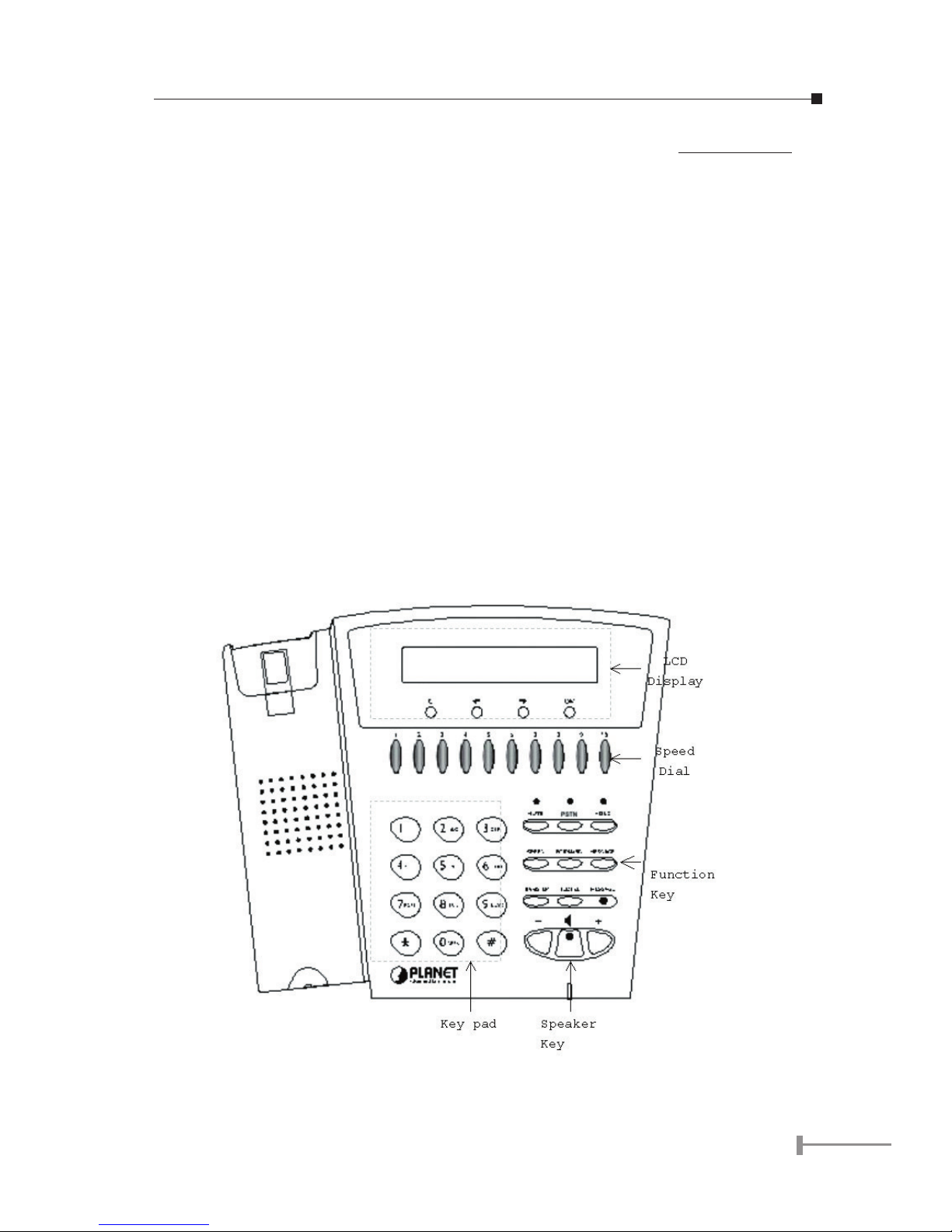
1.2.1 Front view and keypad function:
• C: Cancel and Clear
• çè : Move to left /previous and right/next.
• OK: Press OK to confirm the modification.
• Direct Line (DL) Button 1 – 10: Speed dialing according to phone book data
1-10.
• “+” and “- “ key: Adjust voice volume in communication.
• SPEAKER: Speaking without picking up handset.
• MUTE: Mute the voice of MIC and let others can’t hear from you in communication.
• PSTN: Press PSTN to switch between IP Phone and PSTN calls
• HOLD: To hold a call, after press HOLD button, both sides will hear hold tone
• SPEED: Press SPEED and number (Phone book index) to do speed dial according to phone book data.
• FORWARD: Forward an incoming call to another IP device.
• MESSAGE and its indicated LED light: When missing the incoming calls, the
message LED will be flashing. You can know the information of miss call by
pressing the message button.
• TRANSFER:
1. Transfer a call to third calling party: When call party A and B are in communications, A can press TRANSFER button then the phone number of calling
party C. After calling party C picking up the phone, A can talk to C or hang
up the call to make B and C connected.
M
Caution
When transferring calls, call party A cannot press phone
number of C before hearing dial tone.
During transferring the call, A cannot hangs up before C
picking up the call.
2. Change characters to be capital or lowercase: when press TRANSFER before press letters can switch type of letters.
• REDIAL: Redial the last outgoing call.
• Number 1 –10, * and #: The function is as the same as the general phone
set.
3
• Corresponding list of keypad and symbol:
1 “Space” ; “,” ; “.” ; “!” ; “1”
2 “A” ; “ B” ; “C” ; “2”
3 “D” ; “E” ; “F” ; “3”
4 “G” ; “H” ; “I” ; “4”
5 “J” ; “K” ; “L” ; “5”
6 “M” ; “N” ; “O” ; “6”
7 “P” ; “Q” ; “R” ; “S” ; “7”
8 “T” ; “U” ; “V” ; “8”
9 “W” ; “X” ; “Y” ; “Z” ; “9”
Ü
“-“ ; “?” ; “*”
0 “0”
# “_” ; “@” ; “#”
NOTE:
All function keys mentioned above (except dialing keypad)
are effective only in IP Phone mode.
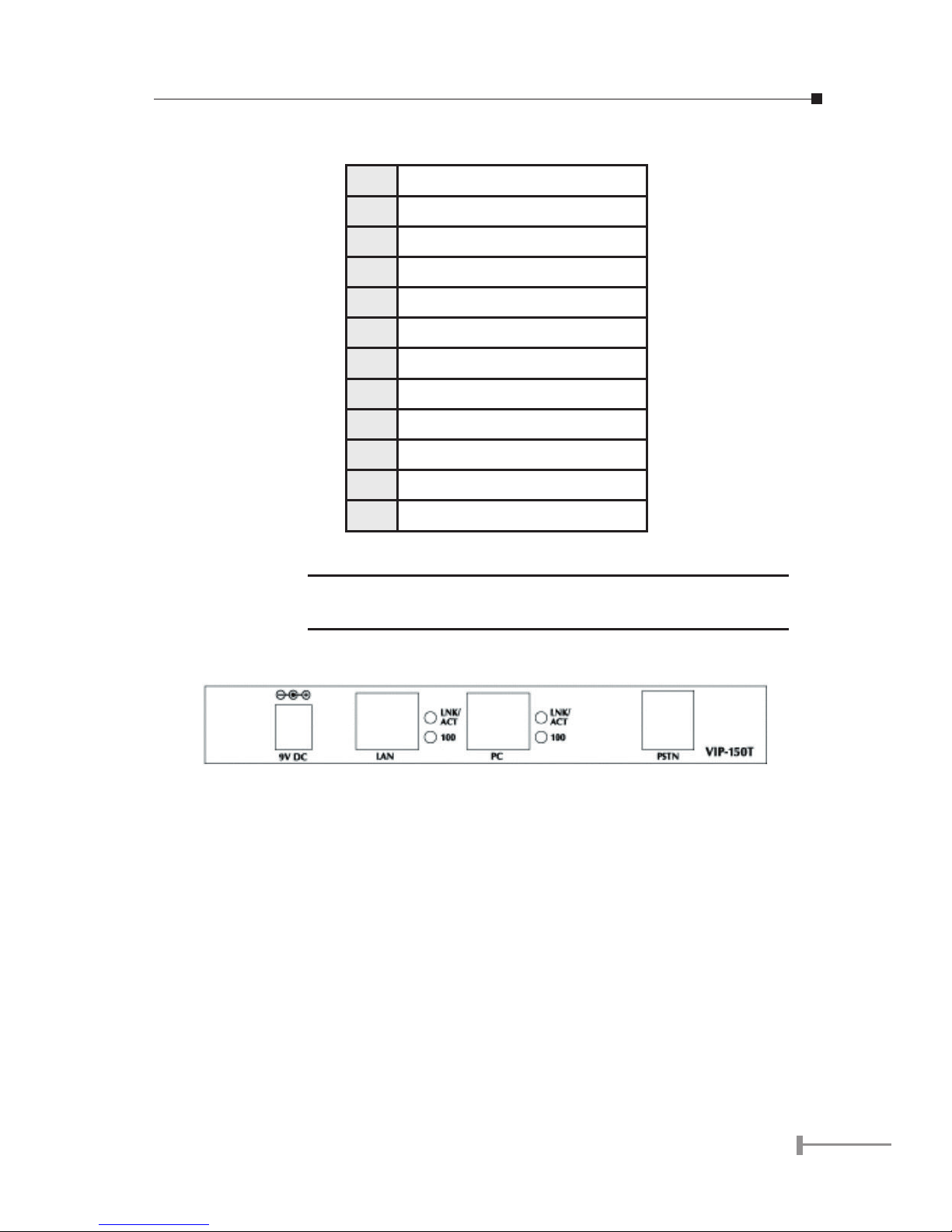
1.2.2 Rear view
9V DC 9V DC Power input outlet
LAN RJ-45 connector, connected directly to Switch/
Hub through straight CAT-5 cable.
PC RJ-45 connector, connected directly to the PC
through straight CAT-5 cable.
PSTN RJ-11 connector, connected directly to the
PSTN analog line.
LED Display Two LED indicated lights; LNK/ACT and 100 for
LAN port and PC port. When network status is
in normal, LED of LNK/ACT will be flashing;
when transmit rate is in 10 Mbps/100Mbps,
LED of 100 will light off/on.

4
5
This page is intentionally left blank
 Loading...