

Page 1
4-Port SIP Internet
Telephony Gateway
VGW-402 / VGW-400FS / VGW-400FO
Page 2

4-Port SIP Internet Telephony Gateway
VGW-400 Series
Copyright
Copyright© 2014 by PLANET Technolog y Corp. All rights reserved. No part of this publication may be reproduced,
transmitted, transcribed, stored in a retrieval system, or translated into any language or computer language, in any
form or by any means, electronic, mechanical, magnetic, optical, chemical, manual or otherwise, without the prior
written permission of PLANET. PLANET makes no representations or warranties, either expressed or implied, with
respect to the contents hereof and specifically disclaims any warranties, merchantability or fitness for any particular
purpose. Any software described in this manual is sold or licensed "as is". Should the programs prove defective
following their purchase, the buyer (and not this company, its distributor, or its dealer) assumes the entire cost of all
necessary servicing, repair, and any incidental or consequential damages resulting from any defect in the software.
Further, this company reserves the right to revise this publication and to make changes from time to time in the
contents hereof without obligation to notify any person of such revision or changes. All brand and product names
mentioned in this manual are trademarks and/or registered trademarks of their respective holders.
Disclaimer
PLANET Technology does not warrant that the hardware will work properly in all environments and
applications, and makes no warranty and representation, either implied or expressed, with respect to
the quality, performance, merchantability, or fitness for a particular purpose. PLANET has made every
effort to ensure that this User’s Manual is accurate; PLANET disclaims liability for any inaccuracies or
omissions that may have occurred. Information in this User’s Manual is subject to change without
notice and does not represent a commitment on the part of PLANET. PLANET assumes no
responsibility for any inaccuracies that may be contained in this User’s Manual. PLANET makes no
commitment to update or keep current the information in this User’s Manual, and reserves the right to
make improvements in this User’s Manual and/or to the products described in this User’s Manual, at
any time without notice. If you find information in this manual that is incorrect, misleading, or incomplete,
we would appreciate your comments and suggestions.
Trademarks
The PLANET logo is a trademark of PLANET Technology. This documentation may refer to numerous
hardware and software products by their trade names. In most, if not all cases, these designations are
claimed as trademarks or registered trademarks by their respective companies.
CE Mark Warning
This is a class B device, in a domestic environment; this product may cause radi o interference, in whi ch
case the user may be required to take adequate measures.
Federal Communication Commission Interference Statement
This equipment has been tested and found to comply with the limits for a Class B digital device,
pursuant to Part 15 of FCC Rules. These limits are designed to provide reasonable protection against
2
Page 3

4-Port SIP Internet Telephony Gateway
VGW-400 Series
harmful interference in a residential installation. This equipment generates, uses, and can radiate radio
frequency energy and, if not installed and used in accordance with the instructions, may cause harmful
interference to radio communications. However, there is no guarantee that interference will not occur in
a particular installation. If this equipment does cause harmful interference to radio or television
reception, which can be determined by turning the equipment off and on, the user is encouraged to try
to correct the interference by one or more of the following measures:
1. Reorient or relocate the receiving antenna.
2. Increase the separation between the equipment and receiver.
3. Connect the equipment into an outlet on a circuit different from that to which the receiver is
connected.
4. Consult the dealer or an experienced radio technician for help.
FCC Caution:
To assure continued compliance, for example, use only shielded interface cables when connecting to
computer or peripheral devices. Any changes or modifications not expressly approved by the party
responsible for compliance could void the user’s authority to operate the equipment. This device
complies with Part 15 of the FCC Rules. Operation is subject to the following two conditions: (1) This
device may not cause harmful interference, and (2) this device must accept any interference received,
including interference that may cause undesired operation.
R&TTE Compliance Statement
This equipment complies with all the requirements of DIRECTIVE 1999/5/EC OF THE EUROPEAN
PARLIAMENT AND THE COUNCIL OF 9 March 1999 on radio equipment and telecommunication
terminal Equipment, and the mutual recognition of their conformity (R&TTE). The R&TTE Directive
repeals and replaces in the directive 98/13/EEC (Telecommunications Terminal Equipment and
Satellite Earth Station Equipment) as of April 8, 2000.
WEEE Caution
To avoid the potential effects on the environment and human health as a result of the
presence of hazardous substances in electrical and electronic equipment, end users of
electrical and electronic equipment should understand the meaning of the crossed-out
wheeled bin symbol. Do not dispose of WEEE as unsorted municipal waste and have to collect such
WEEE separately.
3
Page 4

4-Port SIP Internet Telephony Gateway
VGW-400 Series
Safety
This equipment is designed with the utmost care for the safety of those who install and use it. However,
special attention must be paid to the dangers of electric shock and static electricity when working with
electrical equipment. All guidelines of this and of the computer manufacture must therefore be allowed
at all times to ensure the safe use of the equipment.
Customer Service
For information on customer service and support for Planet Products, please refer to the following
Website URL: http://www.planet.com.tw
Before contacting customer service, please take a moment to gather the following information:
• Internet Telephony Gateway System serial number and MAC address
• Any error messages that displayed when the problem occurred
• Any software running when the problem occurred
• Steps you too k to re solve the problem on your own
Revision
User’s Manual for PLANET Internet Telephony Gateway
Model: VGW-400 Series
Rev: 1.1 (
January, 2014)
4
Page 5

4-Port SIP Internet Telephony Gateway
VGW-400 Series
TABLE OF CONTENTS
Chapter 1 Introduction.................................................................................................................7
1.1 Features...........................................................................................................................................10
1.2 Package Contents ............................................................................................................................12
1.3 Physical Specifications....................................................................................................................12
1.4 Specifications..................................................................................................................................14
Chapter 2 Installation Procedure...............................................................................................20
2.1 Web Login.......................................................................................................................................20
2.2 Configuring the Network Setting....................................................................................................21
2.3 Changing IP Address or Forgotten Admin Password ......................................................................22
Chapter 3 Device Setting ...........................................................................................................23
3.1 Network Configuration ...................................................................................................................23
3.2 Device Time Setting........................................................................................................ ................25
3.3 Device Advance Setting..................................................................................................................27
3.4 User Login Setting ..........................................................................................................................27
3.5 Debug Setting..................................................................................................................................28
3.6 Event Notice....................................................................................................................................29
3.7 Auto Provisioning............................................................................................................................29
3.8 SNMP..............................................................................................................................................30
3.9 PABX Mode ....................................................................................................................................31
Chapter 4 NAT Setting................................................................................................................33
4.1 DHCP Srv. (DHCP Server)..............................................................................................................33
4.2 UPNP (Universal Plug and Play Server).........................................................................................33
4.3 Bandwidth (Bandwidth Control).....................................................................................................34
4.4 URL Filter.......................................................................................................................................38
4.5 IP Filter............................................................................................................................................38
4.6 MAC Filter......................................................................................................................................38
4.7 APP Filter........................................................................................................................................39
4.8 Port Filter ........................................................................................................................................39
4.9 Port Fwd..........................................................................................................................................39
Chapter 5 VoIP Setting...............................................................................................................40
5.1 SIP...................................................................................................................................................40
5.2 Audio...............................................................................................................................................41
5.3 T one.................................................................................................................................................42
5.4 NAT Traversal.................................................................................................................................43
Chapter 6 VoIP Advance.............................................................................................................44
5
Page 6

4-Port SIP Internet Telephony Gateway
VGW-400 Series
6.1 SIP...................................................................................................................................................44
6.2 SIP...................................................................................................................................................47
6.3 Ring.................................................................................................................................................49
Chapter 7 Dialing Plan ...............................................................................................................50
7.1 General............................................................................................................................................50
7.2 Dialing Rule ....................................................................................................................................50
7.3 Digit Manipulation..........................................................................................................................52
7.4 Phone Book.....................................................................................................................................53
Chapter 8 FXS Setting................................................................................................................54
8.1 FXS Line.........................................................................................................................................54
8.2 SIP Proxy.........................................................................................................................................57
8.3 Caller ID..........................................................................................................................................58
8.4 Others..............................................................................................................................................59
Chapter 9 FXO Setting ...............................................................................................................60
9.1 FXO line..........................................................................................................................................60
Chapter 10 SIP Trunk..................................................................................................................63
10.1 Create SIP Trunk...........................................................................................................................63
Chapter 11 Route Plan ...............................................................................................................67
11.1 For PABX Mode Interface.............................................................................................................67
11.2 For Non-PABX Mode Interface.....................................................................................................72
Chapter 12 Status.......................................................................................................................76
12.1 Device Status.................................................................................................................................76
12.2 Line Status.....................................................................................................................................76
12.3 SIP Trunk Status............................................................................................................................77
Chapter 13 Maintenance.............................................................................................................78
13.1 Firmware Update...........................................................................................................................78
Appendix A – Default Setting.....................................................................................................79
Appendix B - Changing IP Address or Forgotten Admin Password ......................................80
6
Page 7

4-Port SIP Internet Telephony Gateway
VGW-400 Series
Chapter 1 Introduction
Cost-effective, High-performance PoE VoIP Phone
To build high-performance VoIP communications at a low cost, PLANET now introduces the latest
member of its gateway family, the VGW-400 enterprise-class 4-port SIP VoIP Gateway series. The
VGW-400 series provides added flexibility during migration to Unified Communications by supporting
the traditional analog devices. These devices include analog phones, fax machines, modems,
voicemail systems, and speakerphones. It helps the company to save money on long-dist ance calls; for
example, the remote workers can dial in through a Unified VoIP Communication System just like an
extension call but no long-distance call charge would occur. The VGW-400 series also allows call to be
transferred to anyone at any location within the voice system, which enables the enterprise to
communicate more effectively and is help f ul to streamline business processes.
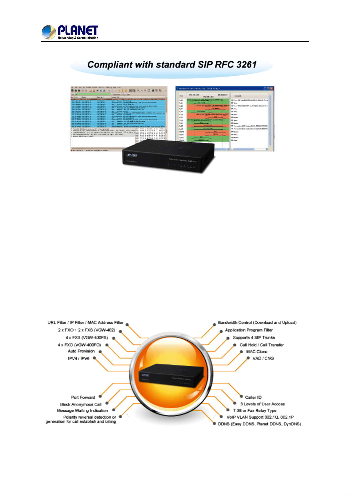
Standard Compliance
The VGW-400 series supports Session Initiation Protocol 2.0 (RFC 3261) for easy integration with
general voice over IP system. The VGW-400 series is able to broadly interoperate with equipment
provided by VoIP infrastructure providers, thus enabling them to provide their customers with better
multi-media exchange services.
7
Page 8
4-Port SIP Internet Telephony Gateway
Enhanced, Full-Featured Business Gateway
VGW-400 Series
The VGW-400 series is a full-featured enhanced business SIP Gateway that addresses the
communication needs of the enterprises. It provides the FXO and FXS gateway with SIP protocol IP
device which allows connection with PSTN telephone line and with analog telephone set to make or
receive VoIP call over Internet or VPN network. This device is suit able for office PABX to enable to have
VoIP call without changing cabling, dial plan and extension number.
The VGW-400 series supports all kinds of SIP-based gateway features and multiple contact filter
functions, such as 4 SIP trunk accounts, both IPv6 and IPv4 protocols, flexible dial plan and route plan
features, and switch analog and VoIP signal to help both protocols to communicate.
8
Page 9
4-Port SIP Internet Telephony Gateway
VGW-400 Series
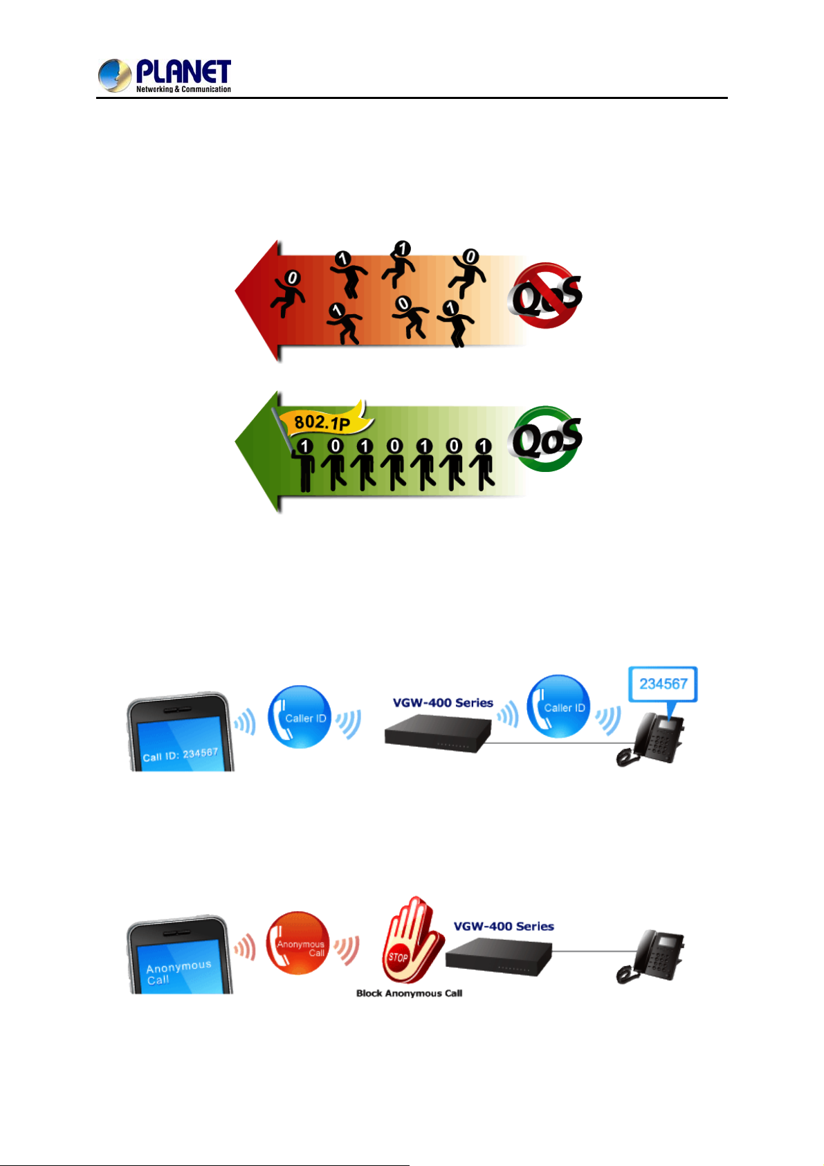
Secure, High-Quality VoIP Communication
It can effortlessly deliver secured toll voice quality by utilizing cutting-edge 802.1p QoS (Quality of
Service), 802.1Q VLAN tagging, and IP TOS (Type of Service) technology. Using voice and data VLAN
can easily separate the data and voice, thus maintaining the best quality.
Supporting Caller ID
Both the FXS and FXO ports of the VGW-400 series support caller ID functio n, help user identify calling
number easily and verify number. It also helps to block anonymous call by filtering strange calls. The
FXS port transmits Caller ID, while the FXO port receives Caller ID. The Caller ID interoperates with
analog phones, public switched telephone networks (PSTN) and private branch exchanges (PBXs).
9
Page 10

4-Port SIP Internet Telephony Gateway
1.1 Features
¾ Highlights
Supports SIP 2.0 (RFC3261)
Supports IPv6 and IPv4 simultaneously
Up to 4 SIP service domains and Caller ID
Supports auto HTTP provision and fax feature
Flexible Routes Plan, Dial Plan and SIP Trunk
Life-line for emergency calls
¾ Internet Features
IPv4 (RFC 791) and IPv6
IPv6 auto configuration (RFC 4862)
VGW-400 Series
IPv6 only, IPv4 only or dual stack
MAC clone setting
Vendor Class ID
DDNS ( Planet DDNS, Easy DDNS, DynDNS)
DNS client
Firewall
URL / IP / MAC / Port Filter
Port forwarding (TCP, UDP or both)
Bandwidth control (download and upload), maximum bandwidth priority setting
¾ SIP Applications
SIP Session Timer (RFC 4028)
SIP Session Refresher: UAC or UAS
SIP Encryption
Supports Outbound Proxy / STUN NAT Traversal
Supports Primary and Backup SIP Server
¾ Call Features
Supports peer to peer dialing
2-line FXO connects to PSTN line
2-line FXS connects to analog phone set or PABX.
Caller ID recognition DTMF (before/after 1st ring) and FSK (before 1st ring ), ETSI and
Bellcore
DTMF Caller ID start and stop BIT configurable
T.38 fax volume configuration
10
Page 11

4-Port SIP Internet Telephony Gateway
¾ FXO/FXS Line Configuration
Line ID / Line Phone number
Polarity Reversal detection or generation for call establish and billing
VoIP dial to FXO/PSTN Line: 1 stage dialing and 2 stage dialing
Outgoing SIP Caller ID selection
Caller ID detection mode by country selection
¾ Routing Plan
Prefix match and length
Priority / Cyclic / Simultaneous Ring
Programmable Hunting Cycle
VGW-400 Series
11
Page 12
4-Port SIP Internet Telephony Gateway
VGW-400 Series
1.2 Package Contents
Thank you for purchasing PLANET Internet Telephony Gateway system, the VGW-400 series. This
Quick Installation Guide will introduce how to finish the basic setting of connecting the web
management interface and the Internet. Open the box of the Internet Telephony Gateway system and
carefully unpack it. The box should contain the following items:
z VGW-400 Series x 1
z Quick Installation Guide x 1
z User’s Manual CD x 1
z Power Adapter x 1 (12V)
z RJ-45 x 1
If any of the above items are damaged or missing, please contact your dealer immediately.
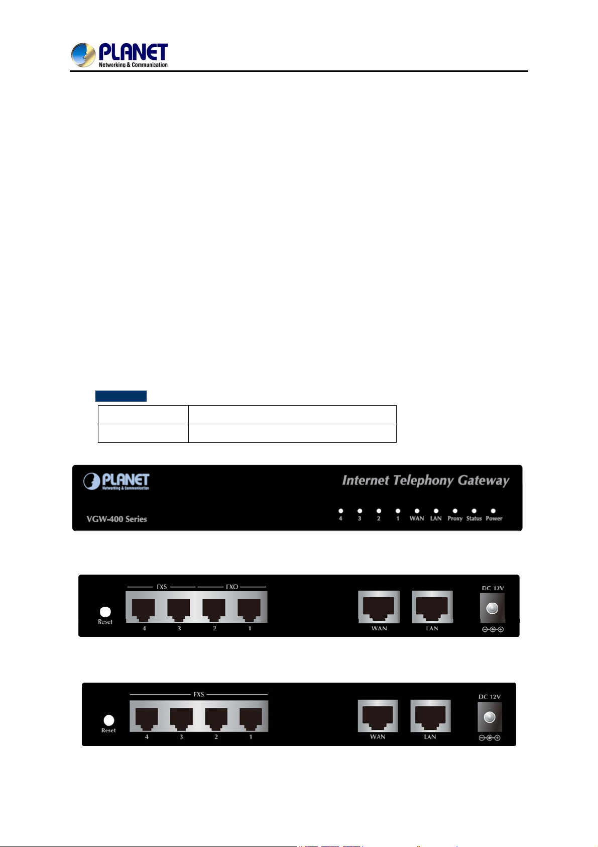
1.3 Physical Specifications
¾ Dimensions
Dimensions
Weight
175 x 32 x126 mm
550g
Front Panel of the VGW-400 Series
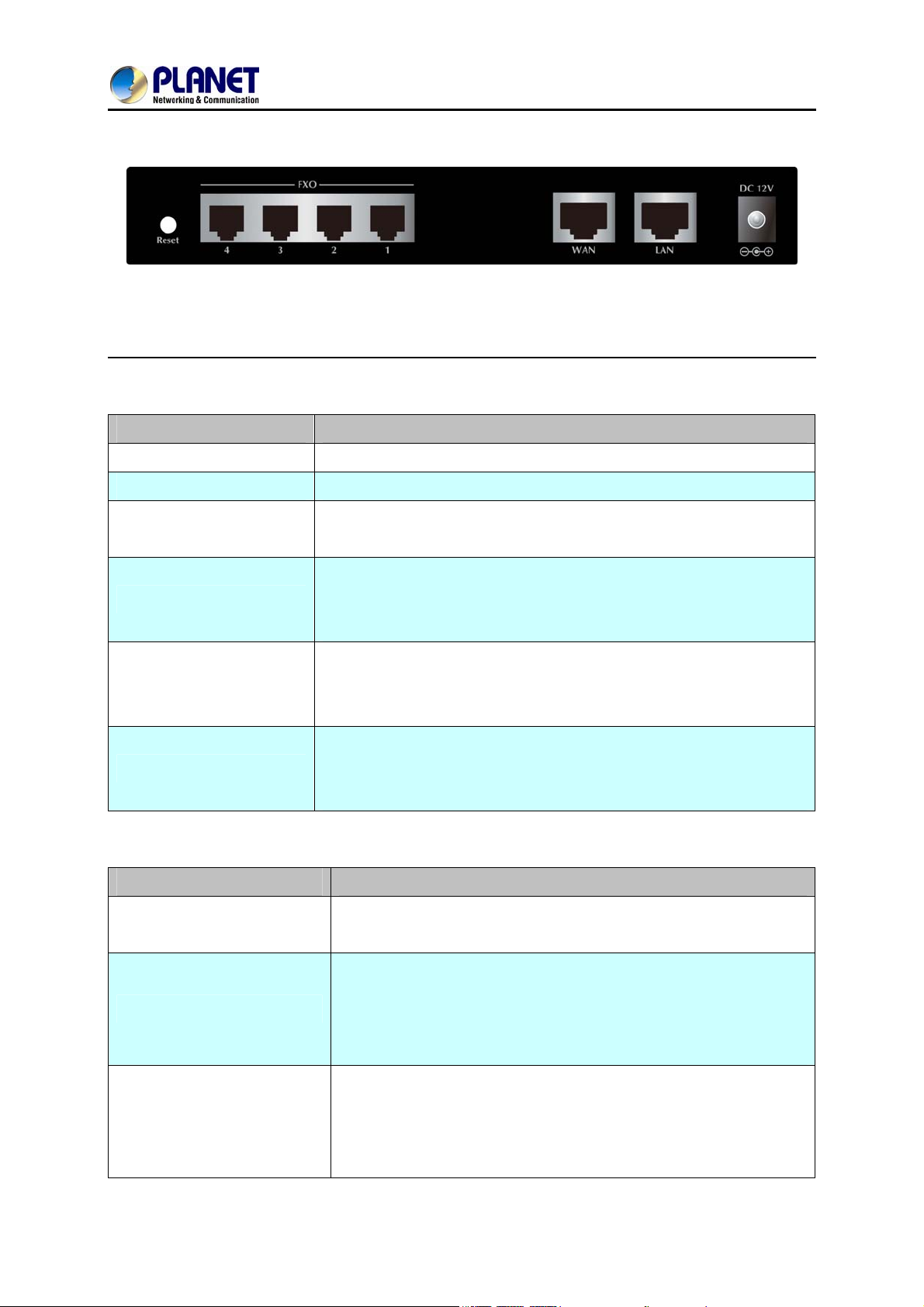
Rear Panel of the VGW-400 Series (VGW-402)
Rear Panel of the VGW-400 Series (VGW-400FS)
12
Page 13
4-Port SIP Internet Telephony Gateway
Rear Panel of the VGW-400 Series (VGW-400FO)
LED definitions
LED Function Description
VGW-400 Series
Power
Status
Proxy
WAN
LAN
Port 1 - 4
When the power adapter is connected, the LED will light up green.
When system startup successfully, the LED will light up green.
When the gateway is registered successfully to a SIP Proxy, this will
light up green.
This LED lights up green when the gateway’s WAN port is physically
connected to the public internet. When data is transmitted through
this port, it will flash green.
This LED lights up green when the gateway’s LAN port is physically
connected to a local network (Refer to Rear Panel section). When data
is transmitted through this port, it will flash green.
The status LED for FXO and FXS ports will light up amber orange when
connected phone is engaged in a conversation mode (FXO). It will
flash amber orange when there is an incoming call (FXS).
Port Function Description
Reset
FXS Ports
FXO Ports
Press and hold over 5 seconds to reload factory default setting,
which will erase all existing settings configured on this gateway.
The status LED for FXS port, will light up amber orange when the
connected phone’s handset is lifted, or when the connected phone is
engaged in a conversation. It will flash amber orange when there
is an incoming call.
The status LED for FXO port will remind you that there is no PSTN
line connected. When PSTN line is connected and there is no
talking, the LED is OFF. When a line is using, the LED becomes
steadily light up.
13
Page 14
4-Port SIP Internet Telephony Gateway
VGW-400 Series
LAN
WAN
DC 12V
10/100Base-TX RJ-45 socket for LAN port connects to PC for
management purposes.
10/100Base-TX RJ-45 socket for WAN port connects to wide area
network.
The power socket, input AC 100V~240V; output DC12V, 1.5A
Button Action Description
Reset
Press less than 5 secs
Press over 5 secs
System reboot
Reset to Factory Default
Please be reminded to reset to factory default. Uploaded music setting (on hold music) and
backup file will not be removed.
1.4 Specifications
Product
Hardware
WAN
LAN
Voice
Protocols and Standard
Data Networking
VGW-400 Series
1 x 10/100Mbps RJ-45 port
1 x 10/100Mbps RJ-45 port
4 x RJ-11 connection
(VGW-402: 2 x FXS, 2 x FXO)
(VGW-400FS: 4 x FXS)
(VGW-400FO: 4 x FXO)
IPv4 (RFC 791) and IPv6
IPv6 auto configuration (RFC 4862)
IPv6 only, IPv4 only or dual stack
MAC address (IEEE 802.3)
MAC clone setting
Vendor Class ID
IP / ICMP / ARP / RARP / SNTP
Static IP
DHCP Client (RFC 2131), WAN port
DHCP Server, LAN port
NAT Server (RFC 1631)
14
Page 15

4-Port SIP Internet Telephony Gateway
VGW-400 Series
PPPoE Client / DNS Client / TFTP Client
DDNS (Planet DDNS, Easy DDNS, DynDNS)
Firewall
URL / IP / MAC / Port Filter
Application Program Filter
Port Forwarding (TCP, UDP or both)
Bandwidth control (download and upload), maximum bandwidth
priority setting
UPnP Server at LAN port
Behind NAT, use DMZ for NAT traversal
SNTP with time zone and Daylight Saving
TCP/UDP (RFC 793/768), RTP/RTCP (RFC 1889/1890), IPV4 ICMP (RFC
792)
VoIP VLAN Support 802.1Q, 802.1P
Voice Gateway
VLAN ID Range: 2 to 4094
VLAN Priority: 0 to 7 (Highest Priority)
QoS: DiffServ (RFC 2475), TOS (RFC791, 1394)
RFC3261 compliance
Supports up to 4 SIP Trunks to Register
SIP UDP Protocol
Supports SIP compact Form
Supports SIP HOLD Type: Send Only, 0.0.0.0 or inactive
SIP Session Timer (RFC 4028)
SIP Session Refresher: UAC or UAS
SIP Encryption
MD5 Digest Authentication (RFC2069/RFC2617)
Reliability of provision response PRACK (RFC3262)
Early/Delay Media support
Offer/Answer (RFC3264)
Message Waiting Indication (RFC3842)
Event Notification (RFC3265)
REFER (RFC3515)
Supports Outbound Proxy
Supports Primary and Backup SIP Server
Supports STUN NAT Traversal
Supports “rport” parameter (RFC 3581)
Configure SIP local Port
15
Page 16

Audio Codec
4-Port SIP Internet Telephony Gateway
VGW-400 Series
SIP QoS Type: DiffServe or QoS
Accept Proxy Only : Yes or No
G.711 A-law/μ-law, G.729A, G.723.1 (6.3K, 5.3K)
Select voice codec priority : Local or Remote
Voice Payload size (ms) configuration
Silence Suppression
VAD/CNG
LEC : Line Echo Canceller
Max Echo Tail Length (G.168): 32, 64 and 128ms
Packet Loss Compensation
Automatic Gain Control
In-band/out of band DTMF (RFC4733, RFC2833 / SIP INFO)
Adaptive/Configurable Jitter Buffer
G.168 Acoustic Echo Cancellation
Functions
Call Functions
Configure RTP basic Port
RTP QoS Type : DiffServ or TOS
Phone Book ( 50 records ) for peer to peer calls
Dialing Plan with drop, replace, Insert dialing digits
Selects first digit and inter digit timeout duration (Sec)
Selectable Call Progress Tone
Support Specified Line Calling
Supports Peer to Peer dialing
FXO connects to PSTN Line
FXS connects to analog phone set or PABX.
Caller ID recognition DTMF (before/after 1st ring) and FSK (before 1st
ring ), ETSI and Bellcore
DTMF Caller ID start and stop BIT configurable
Current Drop Detection to release FXO port
Disconnect tone recognition to release FXO port
Tone Generation: Ring Back, Dial, Busy, Call Waiting, ROH, Warning,
Holding, Stutter Dial Tone and Disconnect Tone
Configure Tone Frequency, Cadence, Level and Cycle
Select Tone specification by Country name List
Global Country based Tone Specification
NAT Traversal supports STUN, UPNP and Behind NAT
Out-Band DTMF with RFC2833 and SIP Info
16
Page 17

4-Port SIP Internet Telephony Gateway
VGW-400 Series
RFC2833 Payload type: 101 or 96
DTMF send out ON and OFF Time configure
DTMF incoming recognition Minimum ON and OFF time
DTMF Relay Volume Configuration
T.38 Fax Volume Configuration
Flash Time transmit via SIP Info (Enable or Disable)
Message Waiting Indication (Stutter Tone Notice)
Blocks Anonymous Call
Call Hold , Call Transfer
Activates or deactivates : Line ID, Line Phone number
Polarity Reversal detection or generation for call establish and billing
Hot Line to desired phone number
Plays voice file to incoming call
FXO/FXS Line
Configuration
Flexible Routing Plan
Repeats playing voice file counts
Self-recorded voice files to upload
Generates FLASH TIME to PSTN network
T.38 or Fax Relay Type
Incoming and outgoing dB value configurable
Dialing Answer Delay time to establish call path
Answers PSTN incoming call after how many ring cycles
Caller ID detection mode by Country selection
VoIP dial to FXO/PSTN Line: 1 stage dialing and 2 stage dialing
Outgoing SIP Caller ID Selection
Supports 4 SIP Trunk
Accepts desired SIP Proxy incoming calls Only
Prefix Match and Length
Priority Ring
Cyclic Ring
Simultaneous Ring
Programmable Hunting Cycle
Backup Routes with Digit Manipulation
Default Routes
17
Page 18

Flexible Dial Plans
4-Port SIP Internet Telephony Gateway
VGW-400 Series
Retrieves transfer call from 3rd party by dial code (default: *#)
Inter digit time out setting
First digit dial out delay time setting
End of dial keypad number
Dial Rule : Match dial prefix and maximum digits length ( 1-15 )
Phone Book can be exported or imported
Flash Time Detection: ranging from 80 to 800 ms
On-Hook Voltage -48Vdc
FXS Analog 2-wire
Interface
FXO Analog 2-wire
Interface
Configure Ring Cadence, Frequency and Voltage
Supports Polarity reversal for Billing
Service Up to 1 Kilo-meter distance to analog telephone set
Generate Current Drop Time (Open Loop Disconnect time)
Incoming Ring frequency recognition range: 10 to 70 Hz
Incoming Ring ON time recognition range: 0 to 8000ms
Incoming Ring OFF time recognition range: 0 to 8000ms
Incoming Ring Level recognition range: 10 to 95Vrms
Flash Time Detection: range from 80 to 800 ms
Configure Ring Cadence, Frequency and Voltage
Administrative Telnet CLI and HTTP, HTTPS
HTTP provision through MAC address
Multilingual Web User Interface
3 Levels of User Access Right with Password protection with different
Web Languages (Administrator, Supervisor and User)
HTTP/HTTPS Service Access limitation from WAN port
Management
Configure Service ports at HTTP, HTTPS and telnet Services
Phone Debug Module: Device Control, Call Control, DB, Verbose
SIP Debug Module: Register, Call, SIP Message, Others
SNTP Debug Module
Device Debug Module
DSP Debug
Provides System Status Logs
Connect to external SYSLOG Server
Status display: Network, Line, SIP Trunk status
Diagnostics (debug through Syslog Event Notice)
Debug in real time by Telnet
Auto Provision via HTTP Server
18
Page 19
Environments
4-Port SIP Internet Telephony Gateway
VGW-400 Series
SNMP V2 / Trap
Configuration Backup/Restore
Dual Firmware Image Backup
Reset to Factory Default
Power Requirements
Operating Temperature
Operating Humidity
Weight
Dimensions (W x D x H)
Emission
Connectors
12V DC, 1.5 A
0 ~ 45 degrees C
10%~90% relative humidity, non-condensing
550g
175×32×126 mm
CE, FCC, RoHS
Two 10/100Base-TX RJ-45 Ethernet ports
Four RJ-11 ports
DC power jack
19
Page 20
4-Port SIP Internet Telephony Gateway
VGW-400 Series
Chapter 2 Installation Procedure
2.1 Web Login
Step 1. Connect a computer to an LAN port on the VGW-400 series. Your PC must set up to the same
domain as 192.168.0.X as the VGW-400 series
Step 2. Start a web browser. To use the user interface, you need a PC with Internet Explorer (version 6
and higher), Firefox, or Safari (for Mac).
Step 3. Enter the default IP address of the VGW-400 series: 192.168.0.1 into the URL address box.
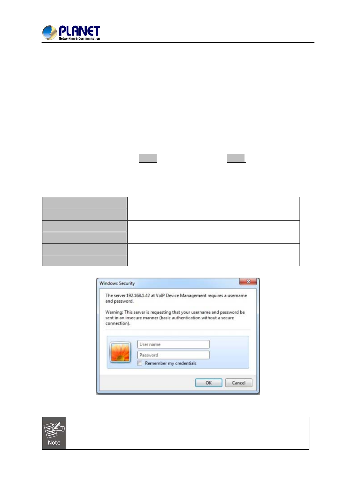
Step 4. Enter the default user name admin and the default password admin, and then click Login to
enter Web-based user interface.
(Default IP)
Default WAN IP
Default Subnet Mask
Default Gateway
Default LAN IP
Default Login User Name
Default Login Password
172.16.0.1
255.255.255.0
172.16.0.254
192.168.0.1
admin
admin
Login page of the VGW-400 series
For security reason, please change and memorize the new password after this first setup.
20
Page 21
4-Port SIP Internet Telephony Gateway
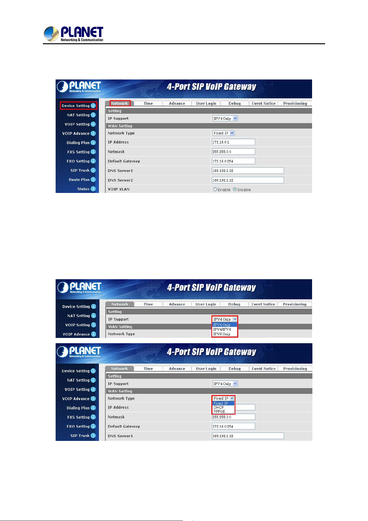
2.2 Configuring the Network Setting
Step 1. Go to Device Setting → Network
Network setting page
VGW-400 Series
Step 2. Edit your WAN port IP information.
There are three types of IP Support -- IPV4 Only, IPV4 / IPV6, IPV6 Only. There are also three types of
WAN port connection -- Static IP, PPPoE (Point-to-Point Protocol over Ethernet) and DHCP. You can
find detailed setting process in the user manual.
Selection of IP Support / Network Connection Type
21
Page 22
4-Port SIP Internet Telephony Gateway
VGW-400 Series
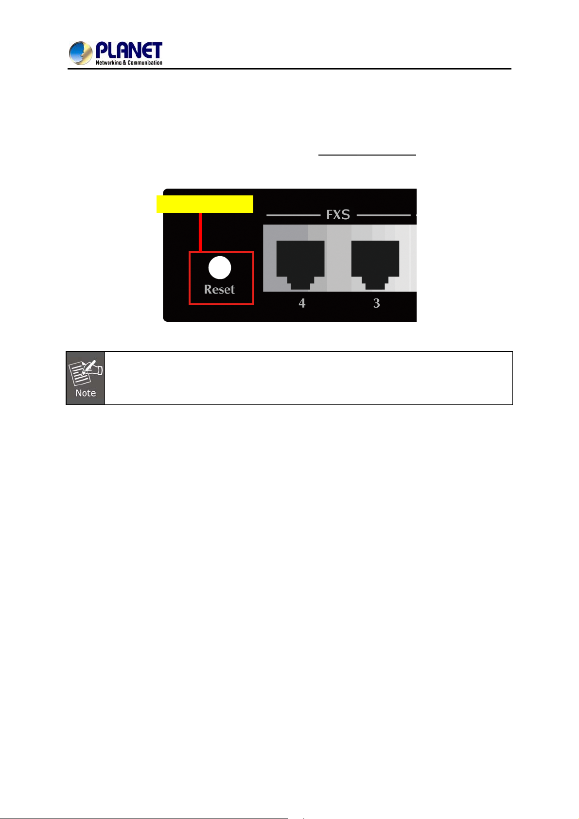
2.3 Changing IP Address or Forgotten Admin Password
To reset the IP address to the default IP Address “192.168.0.1” (WAN) or reset the login password to
default value, press the reset button on the front panel for more than 5 seconds
rebooted, you can login the management WEB interface within the same subnet of 192.168.0.xx.
Reset Button
After pressing the “Reset” button, all the system data will be reset to default; if possible, back
up the config file before resetting.
. After the device is
22
Page 23
4-Port SIP Internet Telephony Gateway
VGW-400 Series
Chapter 3 Device Setting
From this setting category, all devices related to parameters can be found here.
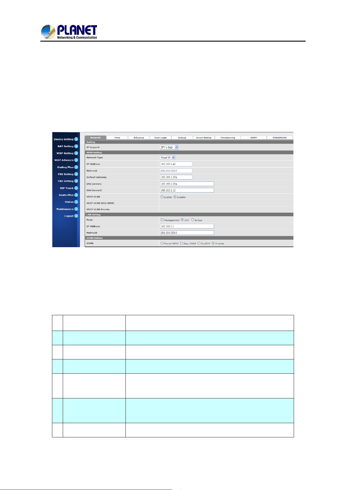
Network Configuration
3.1 Network Configuration
Figure 2-1 network setting
Parameter Description:
Setting
WAN Setting:
:
z IP Support: IP st ack to be supported (IPV6 and IPV4 or IPV6 or IPV4 only)
1 Network Type
2 IP Address
3 Net mask
4 Default Gateway
DHCP Tag (60 is
5
optional)
DHCP Tag (61 is
6
optional)
Support “Fixed IP”; ”DHCP”; ”PPPoE”
IPV4 address
IPV4 network subnet mask
IPV4 Default gateway
Input Vendor class identifier or not.
Input Client identifier or not.
7 IPV6 Network Type
Auto configuration or manual configuration
23
Page 24

4-Port SIP Internet Telephony Gateway
VGW-400 Series
8 IPV6 IP Address
9 IPV6 IP Gateway
10 IPV6 IP Prefix Length
11 DNS Server 1
12 DNS Server 2
13 VoIP VLAN
14 VoIP VLAN ID (2-4096)
LAN Setting:
1 Management Mode
IPV6 address
IPV6 default Gateway
IPV6 prefix length
Primary DNS Server IP network
Secondary DNS Server IP network
Enable VoIP VLAN or not. When enable VoIP VLAN, the WAN
port can be only accessed by VLAN. If it is required to manage
the VGW Gateway series, administrator can use LAN port to
access this gateway instead.
VLAN ID range to be used
This LAN port is used for management purposes, not used for
register to SIP Server or data/voice routing.
2 NAT Mode
3 IP Address
4 Net Mask
5 Bridge Mode
DNS Setting:
1 DDNS
2 Domain Name
DHCP function on the LAN port. The LAN port functions as a
DHCP server. Network devices connected to them will be
assigned one IP address according to DHCP server IP range.
(Please refer to the command of “NAT setting” on the left side for
how to define DHCP IP address.)
IPV4 address
IPV4 network subnet mask
In this mode, both WAN and LAN ports are configured to
Switch/Hub features. LAN port has access to WAN port directly.
It supports Planet DDNS, Easy DDNS and DynDNS or disables
the DDNS feature.
Input your domain name
3 User Name
4 Password
Input your user name
Input your password
24
Page 25

4-Port SIP Internet Telephony Gateway
For more detailed information on Planet DDNS function, please refer to the Appendix:
Planet DDNS page.
3.2 Device Time Setting
The VGW-400 series supports SNTP with time zone and daylight saving.
Device Setting > Time
VGW-400 Series
Configure Time Setting
Parameter Description:
1 Current Time
2 NTP Time Server
NTP Refresh
3
Interval(sec)
4 Time Zone
5 Daylight Saving
6 Daylight Bias
Current time, date and year display.
SNTP time server IP address
The interval time to sync NTP server in seconds
The time-zone where VGW Series Gateway is located.
- Standard: Use a predefined standard time zone
- Customized: Use a user defined time zone
Auto adjust daylight saving time or not
The offset added to the Bias when the time zone is in daylight
saving time
The date that a time zone enters daylight time
7 Daylight Start
- Month: 01 to 12
- Week Day: Sunday to Saturday
- Apply Week (Day:01 to 05, Specifies the occurrence of
25
Page 26

4-Port SIP Internet Telephony Gateway
VGW-400 Series
day in the month; 01 = First occurrence of day, 02 =
Second occurrence of day, ...and 05 = Last occurrence
of day)
- Hour: 00 to 23
The date that a time zone enters daylight time
- Month: 01 to 12
- Week Day: Sunday to Saturday
8 Standard Start
- Apply Week (Day:01 to 05, Specifies the occurrence of
day in the month; 01 = First occurrence of day, 02 =
Second occurrence of day, ...and 05 = Last occurrence
of day)
- Hour: 00 to 23
26
Page 27

4-Port SIP Internet Telephony Gateway
3.3 Device Advance Setting
Parameter Description:
HTTP Service
1
2
HTTPS Service The https web service port (the default is 443)
3
Telnet Service The telnet service port (the default is 23)
The Administrator Web service port (the default is 80)
VGW-400 Series
When clicking the disable option, the Web service will be
HTTP/HTTPS Service
4
Access on WAN
rejected on WAN port. So, please be careful with this function. If
you want to enable WAN port again, you need to
access this device from its LAN port to connect to Web pages and
enable WAN port.
3.4 User Login Setting
Three levels of users can be used, administrator, supervisor and user. Each level of users has a
different predefined access level.
Extension Settings
Item Explanation
Administrator
Supervisor
The administrator level user who has full access authority to VGWGateway series.
The supervisor level user who has limited administrative access
right.
User
features.
The user access right which only allows setting some user related
User ID
Password
Confirm
Login User ID
Login Password
Confirm new password again
Password
Language
The desired web page language used when the account is login.
27
Page 28

4-Port SIP Internet Telephony Gateway
VGW-400 Series
3.5 Debug Setting
The VGW-400 series provides the real-time debug to syslog or through telnet interface. It generates the
debug information based on debug level and modules. Since the generating debug will consume
system resources, it is recommended to turn on only when necessary and under Planet FAE’s
instruction.
Item Explanation
Syslog
Check for Start
Enable or disable to send system information to syslog server or not
Always send syslog or only during a specified time range.
anytime
Syslog Start
(YYYY/MM/DD
HH:MM)
Syslog Stop
(YYYY / MM / DD
HH:MM)
Syslog Server
Syslog Port
DSP Debug
DSP Capture
Always send syslog or only during a specified time range.
The syslog stop sending time
Syslog server IP address
Syslog server service port (default is 514)
Enable or disable to send DSP information to capture log
syslog capture server IP address
Server
DSP Capture Port
syslog capture server service port (default is 50000)
28
Page 29

4-Port SIP Internet Telephony Gateway
VGW-400 Series
3.6 Event Notice
VGW Gateway series can send Syslog Event Notice when it has the following cases:
1. Register Failure or re-registered
2. FXO RJ-11 cable is plugged or unplugged
3. Ethernet reconnected
4. System started
Item Explanation
Syslog Notice
Syslog Server
Syslog Port
Enable or disable to send system events to syslog server or not
Syslog server IP address
syslog server service port (default is 514)
3.7 Auto Provisioning
TheVGW-400 series can be provisioned by HTTP Server for large deployment. Please contact Planet
for availabilities.
29
Page 30

4-Port SIP Internet Telephony Gateway
9510: (This feature is not yet available now. Please don’t select at present.
Select HTTP:
Item Explanation
VGW-400 Series
Http Config URL
Refresh
interval(minute)
User ID
Password
3.8 SNMP
internal use only
interval to check whether there is a new configuration/firmware
or not in minutes
specify the Login ID for http authentication
specify the password for http authentication
SNMP Agent:
Item Explanation
SNMP Agent Enable SNMP or not
Read Only
The community name to read through SNMP protocol
Community Name
Read Write
The community name to read and write through SNMP protocol
Community Name
SNMP Agent Access
Enable SNMP to be accessed through WAN port or not
on WAN
Trusted Peer:
Item Explanation
30
Page 31

Type
IP address
4-Port SIP Internet Telephony Gateway
VGW-400 Series
Any Address:
Any address can retrieve the SNMP information.
Specify an IP Address:
Only the IP address listed can retrieve the SNMP information.
Normally, it will be the SNMP manager’s IP address.
Specify a Subnet:
Only the network specified can retrieve the SNMP information.
The IP address for a trusted peer
Subnet Mask
The network mask for a trusted peer
SNMP Trap:
Item Explanation
SNMP Trap
Destination
Community
Enable SNMP trap or not
The IP address for SNMP manager to receive the SNMP trap
The communication name for sending the SNMP trap
3.9 PABX Mode
This quick setting is dedicated to being used for the VGW-400 series to become an inter-connection in
between PSTN Lines and analog trunk lines from the traditional PABX.
When this mode is changed (enables to disable or disable to enable), it will clear all of the
route plans and return to the default route.
The PABX mode is for VGW-402 Only
The call scenario will be working as follows:
1. For FXO incoming call, it will be routed to corre sponding FXS directly (Line1 to Tel1, Line2 to
Tel2) (For VGW-402 Only)
2. For FXS outgoing call, it will be routed to VoIP except the prefix set in FXO dialing prefix.
3. For VoIP incoming call from SIP Trunk number, it will be routed to FXS based on the called
number.
If you are dialing to SIP trunk number, and hear the dial tone from the VGW Gateway
series, please check the SIP Trunk configuration. It might be configured to option mode at
“1 stage dialing”.
31
Page 32

4-Port SIP Internet Telephony Gateway
VGW-400 Series
4. When VoIP call fails to be called out su ch as registe r failure (this mean s registrat ion to proxy
accounts failed, but not the SIP Trunk number) or network issue. The call will be routed to
FXO as a backup.
5. When the VGW-400 series is malfunctioned, IP netwo rk di sconnecti on o r powe r fail. All calls
will be directly bypassed to FXO automatically.
Item Explanation
PABX Mode Enable or Disable PABX mode, default is “Enable”
32
Page 33

4-Port SIP Internet Telephony Gateway
VGW-400 Series
Chapter 4 NAT Setting
The VGW-400 series can support NAT, 2 Ethernet ports (management mode) or bridge mode. Here is
the setting for NAT related service.
4.1 DHCP Srv. (DHCP Server)
Item Explanation
DHCP Server
Client Range Start
IP
Client Range End IP
Default Gateway
Submask
DNS Server 1
DNS Server 2
Enable DHCP server or not
Specify DHCP client lease start IP
Specify DHCP client lease end IP
Specify the default gateway
Specify the subnet mask
Specify the DNS server 1 addre s s
Specify the DNS server 2 addre s s
4.2 UPNP (Universal Plug and Play Server)
Item Explanation
UPNP Server
Enable UPNP server or not
33
Page 34

4-Port SIP Internet Telephony Gateway
VGW-400 Series
4.3 Bandwidth (Bandwidth Control)
By using bandwidth control feature, the user can manage the traffic based on their needs.
Bandwidth Control:
Item Explanation
Bandwidth Control
Download
Bandwidth
Upload Bandwidth
Maximum Bandwidth and Reserved Bandwidth:
Setup Method: bandwidth control method, percentage or specify the required bandwidth
Percentage: tot
Item Explanation
Priority 1
Priority 2
Priority 3
al bandwidth
Enable bandwidth control or not
Specify total band width for download (unit: kbps). 0 indicates no
limitation
Specify total band width for upload (unit: kbps). 0 indicates no
limitation
highest priority percentage
normal priority percentage
low priority percentage
34
Page 35

4-Port SIP Internet Telephony Gateway
Specifics
Item Explanation
VGW-400 Series
Priority 1 – Download
Priority 2 – Download
Priority 3 – Download
Priority 1 – Upload
Priority 2 – Upload
Priority 3 – Upload
highest priority download bandwidth
normal priority download bandwidth
low priority download bandwidth
highest priority upload bandwidth
normal priority upload bandwidth
low priority upload bandwidth
In order to set which target belongs to which priority, the following are the setting methods for target’s
priority.
IP Target
35
Page 36

4-Port SIP Internet Telephony Gateway
Item Explanation
Priority Priority value for the target
Type The target type is set to IP
Unique IP or a range of IP addresses
¾ Unique:
Configure Type
Port Target
IP Address: the IP address to be set
¾ IP Range:
Start IP: The starting IP for a range
End IP: The stopping IP for a range
VGW-400 Series
Item Explanation
Priority Priority value for the target
Type The target type is set to port number
Unique port number or a range of port number
¾ Unique:
Port: the port number to be added
Configure Type
Protocol: protocol for the port
¾ Port Range:
Start port: the starting port number
End port: the stop port number
Protocol: protocol for the port range
36
Page 37

Application Target
4-Port SIP Internet Telephony Gateway
VGW-400 Series
Item Explanation
Priority
Type
Application
DSCP target
Priority value for the target
Application
The list for the application
Item Explanation
Priority
Priority value for the target
Type
DSCP
The VGW-400 series supports the firewall features below.
DSCP value
The DSCP will be mapped to the priority
37
Page 38

4.4 URL Filter
Item Explanation
4-Port SIP Internet Telephony Gateway
VGW-400 Series
URL Filter
The specified URL will be blocked
4.5 IP Filter
Item Explanation
IP Filter
Local IP address
Protocol
The specified IP address to be blocked
The LAN side IP address to be forwarded
TCP, UDP or both are used for port forward
4.6 MAC Filter
Item Explanation
MAC Filter
For the MAC address to be blocked, please follow these formats.
38
Page 39

4.7 APP Filter
Item Explanation
APP Filter
Application to be blocked
4-Port SIP Internet Telephony Gateway
VGW-400 Series
4.8 Port Filter
Item Explanation
Port Filter
Port Range
Protocol
Enable port filter or not
Starting and stopping port to be forwarded. If you are using only 1
port, please set the starting equal to stopping port
TCP, UDP or both are used for port block
4.9 Port Fwd
Item Explanation
Port Fwd
Port Range
Protocol
Local IP address
Local Port
Enable port forward feature or not
Starting and stopping port to be forwarded. If you are using only 1
port, please set the starting port equal to stopping port
TCP, UDP or both are used for port forward
The LAN side IP address to be forwarded
The LAN side port to be forwarded. If you are using the port range,
this port indicates the starting port
39
Page 40

5.1 SIP
4-Port SIP Internet Telephony Gateway
VGW-400 Series
Chapter 5 VoIP Setting
Item Explanation
Session Timer
Session Expiry
(sec)
Min SE
Session Timer
Refresh Method
PRACK
SIP Local Port
SIP Qos Type
Accept Proxy Only
Enable session timer or not (RFC 4028)
This is the setting of initial session timer expires time according to
RFC4028 - Session Tim ers in the Session Initiation Protocol
The minimum session timer allowed when receiving a call with
session timer value according to RFC 4028
The session timer refresh method
Enable provision ACK or not (RFC 326 2)
The SIP local service port (default is 8080)
Quality of Service Type for SIP signaling
Only accept the call coming from the SIP proxy. Does not accept
peer to peer call in this mode
- None: Disable PRACK
- Supported: When selecting this mode, 100rel will be added
to the support list. It indicates the VGW-400 series can
support the PRACK but not mandatory.
- Require: PRACK is mandatory required.
- None: Not using QOS Tag and not enables QOS.
- DiffServ: Differentiated Services Value. Input DSCP value
0-63 for DSCP
- TOS: Type of Service which include IP precedence value
and TOS.
40
Page 41

4-Port SIP Internet Telephony Gateway
5.2 Audio
Item Explanation
VGW-400 Series
Codec 1~5
G.711u Payload Size
G.711a Payload Size
G.729 Payload Size
G.723.1 Payload Size:
Bit Rate
Codec Priority
The preference codec priority
G.711 u-Law payload size
G.711 A-law payload size
G.729A payload size
G.723.1 payload size
G.723.1 bit rate used
5.3K bit rate is used
6.3K bit rate is used
Selection order to match the remotely SDP for codec selection.
Local SDP Order: Use local SDP order to match codec
Remote SDP Order: Use Remote SDP order to match
codec
In-Band DTMF:
Use inband DTMF instead of out of band.
RFC 2833(fall back to SIP-INFO):
Use RFC 2833 if the SDP negotiation could be done. Or use
DTMF Relay
Silence Suppression
SIP INFO for DTMF relay.
SIP INFO:
Use SIP-INFO DTMF relay
RFC 2833(fall back to Inband):
Use RFC 2833 if the SDP negotiation could be done. Or use
inband DTMF transmission.
Enable: Start the voice activity (silence) detection when
detecting silence for 60 seconds. It will hang up the call (For
FXO use)
41
Page 42

4-Port SIP Internet Telephony Gateway
VGW-400 Series
Disable: Send silence packets as normal voice packet (no
silence detection)
The RTP starting port. Each channel will be added additional
RTP Basic Port
RTP QoS Type
10. For example, the RTP basic port is 16384 and thus call 1
will use 16384 while call 2 will use 16394, etc.
IP QoS tag for RTP stream
DiffServ: The differentiated service QoS tag will be used.
Input DSCP value 0-63 for DSCP.
TOS: Type of Service which include IP precedence value
and TOS.
5.3 Tone
The setting page is used to set up the tone to be generated (FXS) or detected (FXO). The detected
tone is the Disconnect 1 & 2 (for FXO use) and the others are for generating ( when FXS receives the
“bye” from IP side or waits time out by analog phone which keeps picking up the handset, it will
send busy tone to analog phone). To recognize the correct disconnect tone is very important for
PSTN status supervision to release FXO port after call is dropped.
Please use Country Template to select your local country profile which will be applied. Click to load
those country tone parameters to system and change if it is necessary.
For those countries which are not shown in the list, please select a closed country and edit
tone parameters to match your country. You can send an email with the tone definition to
Planet if you would like to put your country tone in the list.
42
Page 43

4-Port SIP Internet Telephony Gateway
VGW-400 Series
5.4 NAT Traversal
The VGW-400 series supports the following NAT traversal methods when it is placed behind the router .
NAT Traversal:
Item Explanation
Disable
STUN (T ype 1,2)
STUN (All)
UPNP
Behind NA T
Disable NAT traversal features
Enable STUN for NAT traversal. Since STUN can be used only
for type 1 and type 2 NAT servers, it is recommended to use
this option. When STUN client detects the current NAT is type
3, it stops the STUN feature operation.
STUN Server: STUN Server IP address
No matter which NA T type server is u sed, STUN is always used
for NAT traversal.
STUN Server: STUN Server IP address
Enable UPnP client for NAT traversal. Please note that the IP
sharing box (or router) needs to support uPnP feature.
Use DMZ for NAT traversal
IP Sharing Address: publi c IP sharing address. You need to
specify the port mapping or DMZ for all required ports
43
Page 44

6.1 SIP
4-Port SIP Internet Telephony Gateway
VGW-400 Series
Chapter 6 VoIP Advance
Item Explanation
SIP on hold message sending method.
Send Only: Set the SDP media to send only when sending an
on-hold SIP message.
SIP Hold Type
SIP Compact Form
0.0.0.0: Set the SDP connection to 0.0.0.0 when sending an
on-hold SIP message.
Inactive: Set the SDP media to inactive when sending an
on-hold SIP message.
Enable SIP compact form or not. When enabling this feature,
44
Page 45

4-Port SIP Internet Telephony Gateway
VGW-400 Series
the connected SIP proxy is required to support compact form.
Who will send dialog to keep message alive (re-invite or
Session Refresher
SIP T1 (msec)
SIP T2 (msec)
update).
UAC: User Agent Client will do the refresh (default setting)
UAS: User Agent Server will do the refresh
T1 determines several timers as defined in RFC3261. For
example, when an unreliable transport protocol is used, a Client
Invite transaction retransmits requests at an interval that st art at
T1 seconds and doubles after every retransmission. A Client
General transaction retransmits requests at an interval that
starts at T1 and doubles until it reaches T2. (Default Value:
500ms) **
Determines the maximum retransmission interval as defined in
RFC3261. For example, when an unreliable transport protocol
is used, general requests are retransmitted at an interval which
starts at T1 and doubles until reache s T2. If a provisional
response is received, retransmission continue but at an interval
of T2. (Default Value: 4000ms) **
T4 represents the amount of time the network takes to clea r
SIP T4 (msec)
Invite Linger Timer
General Linger Timer
Cancel General No
Response Time (msec)
message between client and server transactions as defined in
RFC3261. For example, when it works with an unreliable
transport protocol, T4 determines the time that UAS waits after
receiving an ACK message and before terminating the
transaction. (Default Value: 5000ms) **
After sending an ACK for an INVITE final response, a client
cannot be sure that the server has received the ACK message.
The client should be able to retransmit the ACK upon receiving
retransmissions of the final response for this timer. This timer is
also used when a 222 response is sent for an incoming Invite.
In this case, the ACK is not part of the Invite transaction.
After a UAS sends a final response, the UAS cannot be sure
that the client has received the response message. The UAS
should be able to retransmit the response upon receiving
retransmissions of the request based on this timer.
When sending a CANCEL request on a General transaction,
the User Agent waits for cancel General No Response Timer
milliseconds before timeout termination if there is no response
45
Page 46

4-Port SIP Internet Telephony Gateway
VGW-400 Series
for the cancelled transaction(Default Value: 10,000 ms).**
After sending a General request, the User Agent waits for a
General Request
Timeout Timer (msec)
Cancel Invite No
Response Timer (msec)
Provisional Timer
(msec)
First Response Timer
(msec)
final response general Request Timeout Timer millisecon ds
before timeout termination (in this time the User Agent
retransmits the request every T1, 2*T1,…T2,…milliseconds)**
When sending a CANCEL request on an Invite request, the
User Agent waits for this timer before timeout termination if
there is no response for the cancelled transaction.
The provisional Ti mer is set when receiving a provisional
response on an INVITE transaction. The transaction will stop
retransmissions of the INVITE request and will wait for a final
response until the provision T imer was expired. If you set the
provision Timer to 0, no timer is set. The INVITE transaction will
wait indefinitely for the final response.
When sending a request out, the User Agent waits this timer for
any response received from UAS. If timer is expired and no any
SIP message is received, the User Agent will think the request
is failed. The default is 5 seconds.
You can Enable or Disable the MWI subscription. The default is
MWI Subscription
Expiry (sec)
Line Congestion Code
SIP-Info Flash Mode
Encrypt
600 sec. If a new voice mail arrives, the stutter tone will be used
instead of regular dial tone. This feature is dedicated to FXS
only.
When receiver’s end was contacted successfully from
originated site but the receiver site is busy and does not wish to
answer the call at this time, the system will response the code,
default is 600. (FXO only)
When you enable the feature, system will make flash key to
send SIP message by sip-info.
Disable: disable encryption function.
VGCP is a proprietary layer 2 link proto c ol working at between
IP stack and NIC driver for VoIP anti-blocking. The core
patent-pending VGCP is industry's most st ate-of-art voice
service provider class security protocol whose scalability and
flexibility results in not to compromise voice quality and
overhead. VGCP controls and monitors full voice signaling and
media flow intelligently; meanwhile disguise sip and RTP
packets into normal allowed data packets such as DNS and
46
Page 47

4-Port SIP Internet Telephony Gateway
TFTP, and makes two-way encryption and decryption driven by
user-customized policy. VGCP is fully transparent to upper SIP
proxy or UA whi ch means Voice Guard@ can work with any 3rd
party soft phone / ATA / Gateway / IP Phone / IADs and SIP
Proxy or Server not like some competitors which take effect on
their own device and soft switch.
6.2 Audio
The setting page includes the device related to audio settings.
VGW-400 Series
Item Explanation
RFC 2833 Payload Type
DTMF Send On
Time(msec)
DTMF Send Off
Time(msec)
DTMF Detect Min on
Time (msec)
96 or 101. It is recommended to use 101.
When generating DTMF, the DTMF ON time will be sent
(default value is 70 ms)
When generating DTMF, the DTMF OFF time will be sent
(default value is 70 ms)
The minimum DTMF ON time period will be processed as a
regular DTMF event. A smaller ON time less than this will be
47
Page 48

4-Port SIP Internet Telephony Gateway
VGW-400 Series
ignored. The default value is 60ms.
The minimum DTMF OFF time for the same DTMF value. A
DTMF Detect Min Off
Time (msec)
DTMF Relay Volume
T.38 Fax Volume
T.38 Redundant Depth
T.38 ECM
Min Jitter Buffer (msec)
Max Jitter Buffer
(msec)
Max Echo Tail Length
(G.168)
Jitter Opt. Factor
Impedance
smaller OFF time less than this and the new DTMF digit is the
same as previous one will be handled as 1 digit only (the same
digit but not a new digit).
The DTMF relay volume
The T.38 fax relay volume
The T.38 redundant packet depth. It could be 0 (no redundant),
1 or 2. It is recommended to set to 2.
The T.38 error correction mode. Default value is ON.
The minimum delay time of Jitter buffer.
The maximum delay time of Jitter buffer.
Enable the echo cancellation feature. The default setting is
“128ms”.
Jitter buffer dynamic factor for optimize. Please set to 7 unless
under Planet’s instruction to change.
Selected analog phone’s impedance. (for FXS port use)
48
Page 49

4-Port SIP Internet Telephony Gateway
6.3 Ring
The ring cadence, voltage and frequency were configured to the phone.
Item Explanation
VGW-400 Series
Frequency (10~70HZ)
Ring on (0~8000ms)
Ring off (0~8000ms)
Ring level (10~95volt)
Specify the ringing freque ncy value (default is 20HZ)
Specify the ringing on value (default is 1000msec)
Specify the ringing off value (default is 2000msec)
Specify the ringing level (default is 94 volt RMS value
49
Page 50

4-Port SIP Internet Telephony Gateway
7.1 General
Item Explanation
VGW-400 Series
Chapter 7 Dialing Plan
First Digit Time Out
Inter Digit Time Out
End of Digit
Retrieve Number
7.2 Dialing Rule
Specify the duration of the first digit to be dialed whe n the FXO
port was OFF Hook. The range is 1~60 sec.
Specify the interval of entering between two digit s. If the interval
setting time is expired, the gateway sends out the DTMF digits
immediately. The time range is 1~10 sec.
The assigned key was treated as end of dial and dial out
immediately.
It forces the line to retrieve back if VIP-400 series makes a
transfer call to 3rd party but it DOES NOT answer and put this
call go into voice mail service. You can press the preprogram
code to retrieve back this call from transferred 3rd party. Default
code is “*#”.
Dialing rule is used to speed up the dialing procedure. Some users don’t like to use the end of dialing
digit such as “#”, the administrator can use dialing rule instead. The longest prefix will be matched first.
50
Page 51

4-Port SIP Internet Telephony Gateway
Item Explanation
VGW-400 Series
Dialed Prefix
Max Digits
The following is an example for dialing rule:
Mobile call is starting with 09 and it is 10 digits
Long distance call is starting with 0 and it is 10 digits
International call is starting with 00 and its max digit should be less than 32
The others are local call and 8 digits
Emergency call is starting with digit “1” and length is 3 digits
The Dialing rule can be set as follows:
The prefix to be matched
The digits will be received based on the Dialed Prefix.
Prefix Max. Digits
09 10
0 10
00 15
1 3
2 8
3 8
4 8
5 8
6 8
7 8
8 8
9 8
51
Page 52

4-Port SIP Internet Telephony Gateway
VGW-400 Series
7.3 Digit Manipulation
The Digit Manipulation (DM) will be processed based on prefix and DM group after the DNIS (Called
Party) is determined.
Item Explanation
Different DM groups have dif f erent applications as follows.
FXO: This DM group is used for FXO port with 2-stage
dialing. Af ter the DNIS (Called party messages) is
DM Group
Matched Prefix
Matched Length
Start POS
Stop POS
collected, this DM group will be processed before entering
the routing procedure.
FXS: This DM group is used for FXS dial out.
VOIP: This DM group is used for VOIP incoming call. Af ter
the DNIS is collected in 2-stage dialing or 1-stage dialing,
this DM group will be processed before entering the
routing procedure.
1-4: These DM groups are used for backup routing
purpose. When a backup routing is used, the
administrator can select a DM group to be processed
before starting the backup routes.
The prefix to be matched for DM. The longest prefix will be
matched first
Set to 0 to ignore the length. The other 1-32 are the digit length
to be matched as a condition
The start digit position to be replaced
The stop digit position to be replaced
Replace Value
The value to be replaced
52
Page 53

4-Port SIP Internet Telephony Gateway
Example of Digit Manipulation Settings:
VGW-400 Series
Prefix Len Start
POS
886 0 0 0 002 8862123456 0028862123456
886 12 0 0 002 8862123456 8862123456
886 0 2 5 002 8862123456 8800223456
886 0 30 30 002 8862123456 8862123456002
886 0 1 6 8862123456 83456
Stop
POS
Replace
Value
Test DNIS
(called number)
Result DNIS
(dial-out called number)
7.4 Phone Book
Phone Book is used for peer to peer call.
Item Explanation
Name
Tel No
This field supports called number only. If you enter words or
text here, it will route to proxy server automatically
Enter called number and IP address. Please follow this sample
of picture, as the format of “number@uri:port”. (default port is
Export
Import
5060)
To back up the phone book records
To reload setting of phone book
53
Page 54

4-Port SIP Internet Telephony Gateway
Chapter 8 FXS Setting
The FXS line setting includes each number and SIP proxy settings.
8.1 FXS Line
Item Explanation
VGW-400 Series
Line ID
State
Tel. No
Hotline T el.
FXS line
The line is active or not
The telephone number of each FXS port
If hot line is enabled, this field shows the hot line number
54
Page 55

4-Port SIP Internet Telephony Gateway
VGW-400 Series
Item Explanation
Line ID
Line Type FXS or FXO (depending on device model).
Line State
Forward reasons:
FXS Line number (T1 to T2)
Set to active if you would like to use this line. Otherwise, set to
inactive.
Unconditional forward: forward this call without any
condition.
Busy forward: Forward the call when phone is busy.
No answer forward: forward the call when the call is not
answered after any answer timeout.
Forward Tel.: The telephone number will be forwarded once
55
Page 56

4-Port SIP Internet Telephony Gateway
VGW-400 Series
Forward mode is activated.
No Answer Timeout
(seconds)
Call Waiting
Reject Anonymous Call
Hot Line
Hotline T el
Polarity Reversal
Generation
Current Drop
Generation
The no answer timeout will be used (default is 120 sec)
Enable call waiting or not. When call waiting mode is disabled,
the second incoming call will be rejected.
Reject the anonymous incoming call or not
Enable to disable hot line feature
The number will dial automatically after the user picks up the
phone.
Enable Polarity Reversal of tip/ring of RJ-11 phone line for FXS
as billing signal or not. When an FXS calls to VOIP and
answered by the remote party, VGW-400 Series generates
reverse signal to FXS as a billing start. When VoIP side
disconnects call, VGW-400 Series reverses back as a billing
stop signal.
Enable current drop (0 voltage) when VoIP is disconnected
(Remote party drops the call).
Input (Encode) Gain
Output(Decode)Gain
Fax Relay
Voice Mail Subscription
Caller ID Mode
SIP Caller ID Mode
Register Type
Adjust the volume from FXS/FXO to IP side (default is 0 dB)
Adjust the volume from IP side to FXS/FXO (default is 0 dB)
Enable T.38 Fax Relay or T.30 Fax Bypass or not.
(T.30 Fax Bypass only supports G711a law)
Enable voice mail subscription (MWI) or not.
Inhibit: don’t send caller ID to analog phone.
Transparent: send caller ID to analog p hone.
Inhibit: don’t send caller ID to IP SIP side
Transparent: send caller ID to IP SIP side
Register: register to proxy. If it is not registered to SIP
proxy, the FXS line still can use SIP trunk for VoIP call.
Predefine: When it is set to predefine, VGW-400 Series
does not send registered message out.
Internal: When it is set to internal, VGW-400 Series does
not send registered message out. The FXS line still can use
SIP trunk for VoIP call or call locally.
Tel No
User ID
User Password
Display Name
The registrar telephone number
The SIP user ID for register and call making
The SIP password for register and call making
The SIP display name
56
Page 57

4-Port SIP Internet Telephony Gateway
8.2 SIP Proxy
The SIP proxy server defined here is dedicated to FXS lines.
VGW-400 Series
Item Explanation
Domain
Primary Proxy Server
Primary Proxy Server
Port
Outbound Proxy Server
Outbound Proxy Server
Port
Primary Proxy Server
Keeps Alive
Keep Alive Time(sec)
Secondary Proxy
The SIP domain for register or call making
Primary SIP registrar server address
Primary SIP registrar server port number
Primary outbound proxy server address
Primary outbound proxy server port number
Using NAT to keep the port alive
Specify time to send SIP registered message to proxy server.
Enable secondary proxy or not. When enabling it, the primary
and secondary proxies will be registered at the same time.
57
Page 58

4-Port SIP Internet Telephony Gateway
VGW-400 Series
Secondary Proxy
Server
Secondary Proxy Port
Secondary Outbound
Proxy Server
Outbound Proxy Server
Port
Register Expiry:
Secondary Proxy
server keep Alive
Keep Alive Time(sec)
Secondary SIP registrar server address
Secondary SIP registrar server port number
Secondary outbound proxy server address Secondary
Secondary outbound proxy server port number
SIP register time to leave
Using NAT to keep the port alive
Specify time to send SIP register message to proxy server.
8.3 Caller ID
The call ID sends to FXS port of the analog phone set to display caller name or phone number.
58
Page 59

4-Port SIP Internet Telephony Gateway
Item Explanation
VGW-400 Series
Caller ID Mode
Polarity Reverse before
Caller ID
Dual Tone before Caller
ID
Caller ID present
DTMF Caller ID Start
Digit
DTMF Caller ID Stop
Digit
8.4 Others
Caller ID mode to be used for phone (FSK Bellcore, FSK ETSI,
DTMF)
Start polarity reverse to FXS port before sending the caller ID
Send Dual Tone before caller ID (for FSK ETSI use only)
The timing to send the caller ID
(Before the first ring, after the first ring, after the first short ring)
Specify the DTMF caller ID start digit (default is D, the range is
A to D or #)
Specify the DTMF caller ID start digit (default is C, the range is
A to D or #)
Flash time and current drop generation/detection time
59
Page 60

4-Port SIP Internet Telephony Gateway
The FXO setting contains the FXO related parameters.
Item Explanation
VGW-400 Series
Chapter 9 FXO Setting
Line ID
State
Tel No
Hotline T el
9.1 FXO line
FXO line
The line is active or not
The reference telephone number (e.g. PSTN Tel line)
If hot line is set, this field shows the hotline number
60
Page 61

4-Port SIP Internet Telephony Gateway
Item Explanation
VGW-400 Series
User ID
User T ype
Line State
Tel No
Polarity Reversal
Detection
Current Drop for
Disconnection
FXO Line number
The line type is FXO
Set to active if this Line is activated. Otherwise, set to inactive.
This field can be used as a reference remark for this line.
Normally, you can put the connected PSTN line’s phone
number here for reference.
When enabling the Polarity Reversal Detection feature,
VGW-400 Series uses the polarity reversal signal once call is
established for FXO outgoing call and start to count talking time
for billing purpose. When disabling the polarity Reversal
Detection, VGW-400 Series uses “Dialing Answer Delay
Time” command to set time (seconds) to start billing time once
SIP call is established.
Use Line current drop as a disconnecting supervision to release
FXO port. When remote PSTN side user drops call, the local
PSTN switch sends Current drop signal to FXO port to
Incoming Call Handling
Playback Voice File
Repeat Count
Voice File Name
(MuLaw-mono 8K)
recognize this situation.
The call handling policy for an FXO incoming call.
Hotline Tel: When a PSTN Line incoming call is detected
and after the FXO answers this call based on the Ring
Count Configuration, the VGW-400 series sends SIP call to
the specified hotline tel number through the Route Plan.
2 Stage Dialing: When a PSTN Line incoming call is
detected and after the FXO answers this call based on the
Ring Count Configuration, VGW-400 Series answers this
call and plays either Dial Tone or Voice Greeting file to
PSTN side. And wait for th e PSTN side user to dial number
to send to IP SIP Trunk or FXS ports.
To enable playing voice greeting file or not. (Used for FXO port
Only)
Repeat how many counts to play voice greeting file. (Used for
FXO port with 2-Stage Dialing Only )
Specify the file path and file name to upload. Please make sure
that the file format needs to be G.711U, 8K, 8 bits raw file.
(Used for FXO port Only)
Flash Time
Flash Time wi ll be sent to PSTN line.
61
Page 62

4-Port SIP Internet Telephony Gateway
VGW-400 Series
Fax Relay
Input (Encode) Gain
Output (Decode) Gain
Dialing Answer Delay
Time (sec)
PSTN Answer Ring
Count
To enable T.38 Fax Relay or T.30 Fax Bypass or not.
(T.30 Fax Bypass only supports G711a law)
Adjust the volume from PSTN to IP side (default is 0 dB)
Adjust the volume from IP side to PSTN (default is 0 dB)
When the polarity reversal detection is disabled, VGW-400
Series answers the call (establish call between VoIP and FXO)
after time out to start billing count purpose. After the DTMF
digits dialing, VGW-400 Series sends 183 with SDP to SIP
Trunk to enable the voice path for VoIP side.
This ring count is used for called ID detection and 2-stage
dialing.
z If the caller ID is sent between the first ring and the
second ring, this parameter should be set to greater than
or equal to 2.
z If the caller ID is sent before the first ring, this parameter
can be set to greater or equal to 1.
After the ring count is reached, VGW-400 Series answers the
Caller ID Mode
call and plays voice greeting file if 2-stage dialing is selected.
Or, make the VOIP call out directly if hotline mode and number
is selected.
The detected Caller ID specification from the PSTN line based
on selected country list or FSK or DTMF.
62
Page 63

4-Port SIP Internet Telephony Gateway
VGW-400 Series
Chapter 10 SIP Trunk
The SIP trunk for VoIP outgoing call and incoming call can be configured by administrator authority .
There are up to 4 SIP trunks that can be used.
Please don’t delete SIP trunk, even it is useless because it has to be used with route plan.
10.1 Create SIP Trunk
63
Page 64

4-Port SIP Internet Telephony Gateway
Item Explanation
VGW-400 Series
Trunk ID
Register Type
Tel No
Proxy Server
Proxy Server Port
Outbound Proxy
Outbound Server Port:
SIP trunk ID 1 to 4
Register type is predefined or registered
The tel no for the SIP account
The SIP proxy server address
The SIP proxy server port number
The SIP outbound proxy server address
The SIP outbound proxy server port
64
Page 65

4-Port SIP Internet Telephony Gateway
Item Explanation
VGW-400 Series
Trunk ID
Register Type
Domain
Proxy Server
Proxy Server Port
Outbound Proxy Server
Outbound Proxy Server
Port
Register Expiry
Tel No
User ID
SIP trunk ID 1-4
Whether this account needs to register or not
Register: When it is set to register, VGW-400 Series
sends REGISTER message to SIP proxy server for
registration.
Predefine: When it is set to predefine, VGW-400 Series
DOES NOT send REGISTERED message out.
The SIP domain for register or call making
SIP registrar server address
SIP registrar server port number
Outbound proxy server address
Outbound proxy server port number
The default register expired for negotiation
The registrar telephone number
The SIP user ID for register and call making
User Password
Display Name
Reject Anonymous Call
Outgoing Caller ID
The SIP password for register and call making
The SIP display name
Reject the anonymous call
The outgoing SIP caller ID mode.
-Display Name: The display name will be set as follows:
None: No display name will be used
PSTN caller ID: The display name will be the collected PSTN
caller ID
SIP display name: The display name will be the Display Name
set in this SIP trunk.
FXO Tel No: The display name will be the incoming FXO’s Tel
No. set on FXO lines.
User ID: The SIP caller ID will be used as follows:
z SIP user ID: If the SIP user ID is set, the SIP user I D set
in this SIP trunk will be used and the domain/SIP proxy will be
the host part. The SIP from header’s URL will be the
SIP_User_ID@Domain or SIP_User_ID@SIP_Proxy_Server.
z PSTN caller ID: If the PSTN caller ID will be used in
SIP URL, the SIP from header’s URL will be
65
Page 66

4-Port SIP Internet Telephony Gateway
VGW-400 Series
PSTN_Caller_ID@local_IP_address.
z FXO Tel No: If the FXO Tel No will be used in SIP URL,
the SIP FROM header’s URL will be
FXO_Tel_NO@local_IP_address.
The following guidelines could be used for most cases:
1. If the VGW-400 series in SIP proxy is handled as a
gateway, please set both the display name and User ID to
“PSTN caller ID”.
2. If the VGW-400 series in SIP proxy is handled as a
subscriber , please set the display name to “PSTN caller ID” and
User ID to “SIP User ID”.
When you have a call from VoIP to FXO to call out to PSTN
network, there are two methods that can be used. ( FXO port
For DNIS is Registered
Tel
Keep Alive
dialing out only )
1-stage dialing: When there is an SIP trunk incoming call to
the VGW-400 series, it selects a free FXO port and dial-out
digits directly without doing DM and route plan directly.
If the VGW-400 series is configured to PABX
mode, the incoming call from VoIP or FXO port
only routes to FXS port. However, the outgoing
call from FXS port goes to either VoIP or FXO
port depending on DM and route plan.
2-stage dialing: When there is an SIP trunk incoming call to
the VGW-400 series, it answers this call and plays dial tone
to SIP trunk to wait for SIP trunk user to dial digits and send
these digits to FXO/PSTN network one by one.
Enable or Disable it.
Keep Alive Ti me (sec)
Specify interval time to send SIP registered message to proxy
server.
66
Page 67

4-Port SIP Internet Telephony Gateway
VGW-400 Series
Chapter 11 Route Plan
The routing policy is the core feature of the VGW-400 series. The p olicy is based on incoming call type,
destination, length and prefix code to determine the outgoing call routes and process. There are three
routes to go for each incoming call port as shown below.
The following rules do not apply to PABX mode. (For VGW-402 only)
1. VoIP incoming call to the VGW-400 series -- It routes to either FXO or FXS interface and vice versa.
2. FXO incoming call to the VGW-400 series -- It routes to either VoIP or FXS interface and vice versa.
3. FXS incoming call (it means FXS off hook and dialing out) to the VGW -400 series -- It routes to either
FXO or VoIP interface and vice versa.
11.1 For PABX Mode Interface
For this application, FXS outgoing call is routed to either VoIP or FXO and vice versa. The default route
is that VoIP incoming call is routed to FXS and FXS call is routed to VOIP network.
The PABX mode follows these rules to route call as follows:
1. When FXO has an incoming call to the VGW-400 series, it routes to FXS port only.
2. When VoIP has an incoming call to the VGW-400 series, it routes to FXS port only.
3. When FXS makes a dial out, the route call is redirected to either VoIP or FXO according to this
gateway’s DM and routing plan.
67
Page 68

4-Port SIP Internet Telephony Gateway
Item Explanation
VGW-400 Series
Incoming Call Type
Matched Prefix
Matched Incoming List
Matched Length
Outgoing Type
Create Route Plan>
Click “Route Plan” and then create a new routing policy.
The incoming call port is FXS or VOIP.
Matched DNIS (called number) prefix
Matched DNIS incoming interface target
Matched DNIS (called number) length. The zero (0) means no
limitation of length.
The outgoing call from FXS port can only go to either FXO or
VoIP.
68
Page 69

4-Port SIP Internet Telephony Gateway
VGW-400 Series
69
Page 70

4-Port SIP Internet Telephony Gateway
Item Explanation
Incoming call type
VGW-400 Series
Incoming Call Type
Matched Prefix
Matched Incoming List
Matched Length
No Answer Timeout
z VoIP: The incoming SIP call type
z FXS: The FXS extensions incoming call type
Matched DNIS (called number) prefix
Matched DNIS incoming interface target
For FXS incoming call type, the incoming target will be the line
ID. Only the call from the selected line will be accepted for this
route.
Matched DNIS (called number) length. To ignore the length,
please set to 0.
How long does the hunting continue to next when the called
target doesn’t answer?
70
Page 71

4-Port SIP Internet Telephony Gateway
Create Route Plan>Primary Route
Item Explanation
VGW-400 Series
Outgoing Type
Hunting Type
DM Group
Create Route Plan>Backup Route
Item Explanation
Backup Route
Outgoing Type
Outgoing call type (FXO or VOIP or FXS)
The hunting method can be used for this route.
z Priority Ring: The call was hunted based on the routing
list order one by one.
z Cyclic Ring: The call was hunted based on the cyclic
basis. This is the recommended method.
z Routing List:
The routing target list is used for this route.
Select DM group 1 to 4 in case it requires a DM route (for
example, remove the prefix) before making the call.
Activate the backup route or not.
Define backup route outgoing call type.
Hunting Type
Routing List
Route DM Group:
2 special default routes, “VoIP Default Route” and “FXS Default Route”, are used as the default routing
when there is no other matched routing. It is not recommended to disable these 2 default routes. The
FXS default route is used as FXS outgoing call’s default route. VoIP default route is used as VoIP
incoming call’s default routing.
The hunting method is used for this route. Please refer to the
Primary Route.
The backup routing target list is used for this route
Select DM group 1 to 4 in case the backup requires the DM
before making the call. The DNIS is unchanged by the primary
route DM and the same as the DNIS before routing. For
example, the DNIS is 886282265699 and primary DM group
removes 886 and use it (DNIS = 282265699) to make call.
When backup route is started, the DNIS is still unchanged as
886282265699. This makes the DM easy to predict and
implement.
71
Page 72

4-Port SIP Internet Telephony Gateway
VGW-400 Series
In this mode all of the V oIP and FXO incoming calls are forced to route to FXS
port. The VoIP incoming call can’t route to FXO port to dial out.
11.2 For Non-PABX Mode Interface
For this interface, it could be routed to VoIP, FXO and FXS, and vice versa. You can ignore the routing
plan if you don’t need it for FXS interface.
Item Explanation
Incoming Call Type
Matched Prefix
Matched Incoming List
Matched Length
Outgoing Type
Incoming call type (VoIP or FXS or FXO)
Matched DNIS (called number) prefix
Matched DNIS incoming interface target
Matched DNIS (called number) length
The outgoing call type (FXS or VOIP or FXO)
72
Page 73

4-Port SIP Internet Telephony Gateway
VGW-400 Series
Item Explanation
Incoming call type
Incoming Call Type
Matched Prefix
Matched Incoming List
z VoIP: The incoming SIP call type
z FXO: The PSTN incoming call type
z FXS: The FXS outgoing call type
Matched DNIS (called number) prefix
Matched DNIS incoming interface target
z For the VoIP incoming call type, the incoming target will be
z For the PSTN (FXO port) incoming call type, the incoming
z For the FXS incoming call type, the incoming target will be
the SIP trunk ID. Only the call from the selected SIP Trunk
will be accepted for this route.
target will be the line ID. Only the call coming from the
selected line will be accepted for this route.
the line ID. Only the call coming from the selected line will be
accepted for this route
73
Page 74

4-Port SIP Internet Telephony Gateway
VGW-400 Series
Matched Length
No Answer Timeout
Create Route Plan>Primary Route
Item Explanation
Outgoing Type
Hunting Type
Matched DNIS (called number) length. To ignore the length,
please set to 0
How long does the hunting continue to next when the called
target doesn’t answer?
Outgoing call type (FXO or FXS or VOIP)
The hunting method is used for this route.
z Priority Ring: The call is hunted based on the routing list
order one by one.
z Cyclic Ring: The call is hunted based on the cyclic basis.
This is the recommended method.
z Routing List:
The routing target list is used for this route.
DM Group
Create Route Plan>Backup Route
Item Explanation
Backup Route
Outgoing Type
Hunting Type
Routing List
Route DM Group
Select DM group 1 to 4 in case it requires a DM (for example,
remove the prefix) before making the call
Activate the backup route or not
The backup route outgoing call type
The hunting method will be used for this route. Please refer to
the Primary Route
The backup routing target list will be used for this route
Select DM group 1 to 4 in case the backup requires the DM
before making the call. The DNIS is unchanged by the primary
route DM and same as the DNIS before routing. For example,
the DNIS is 886282265699 and primary DM group removes 886
and use it (DNIS = 282265699) to make a call. When backup
route is started, the DNIS is still unchanged as 886282265699.
This makes the DM easy to predict and implement.
Three special default routes, “VoIP Default Route”, “FXO default Route” and “FXS default Route”, are
used as the default routing when there is no other matched routing. It is not recommended to disable
74
Page 75

4-Port SIP Internet Telephony Gateway
VGW-400 Series
these three default routes. The FXO default route is used when there is an FXO incomi ng call’s default
routing. VoIP default route is used for a VOIP incoming call’s default routing. FXS default route is used
when an FXS outgoing call default is routing.
75
Page 76

12.1 Device Status
4-Port SIP Internet Telephony Gateway
VGW-400 Series
Chapter 12 Status
Item Explanation
Model
MAC Address
Network Type
IP Address
IPV6 IP Address
Firmware
The model number
The MAC address of the VGW-400 series
The Network Interface Type settings
IP address is used
Display IPV6 address
The firmware version
12.2 Line Status
76
Page 77

4-Port SIP Internet Telephony Gateway
Item Explanation
VGW-400 Series
Line
Call Status
Refresh Interval
(second)
L1 to L4
The status of this line
The time to refresh the status
12.3 SIP Trunk Status
Item Explanation
Account
Registered
Concurrent Call
Refresh Interval
(second)
SIP trunk account
The SIP trunk register status
The concurrent calls are used for this SIP trunk
The time to refresh the status
77
Page 78

4-Port SIP Internet Telephony Gateway
VGW-400 Series
Chapter 13 Maintenance
The VGW-400 series can be managed by this management page to upgrade firmware or reset this
device.
Item Explanation
Backup
Restore
Reset to Default
Quick Reset
Reboot
Back up the system settings for restoring purpose
Restoring the backup setting to this device
Reset system setting to factory default value.
Warm reset without rebooting this device.
Reboot this device
13.1 Firmware Update
This maintenance page provides the firmware upgrade features.
78
Page 79

4-Port SIP Internet Telephony Gateway
VGW-400 Series
Appendix A – Default Setting
Default WAN IP
Default subnet mask
Default Gateway
Default PC IP
Default Login User Name
Default Login Password
172.16.0.1
255.255.255.0
172.16.0.254
192.168.0.1
admin
admin
79
Page 80

4-Port SIP Internet Telephony Gateway
VGW-400 Series
Appendix B - Changing IP Address or Forgotten
Admin Password
To reset the IP address to the default IP address “192.168.0.1” (LAN) or reset the login password to
default value, press the reset button on the front panel for more than 5 seconds
rebooted, you can login the management Web interface within the same subnet of 192.168.0.xx.
Reset Button
After pressing the “Reset” button, all the system data will be reset to default; if possible, back
up the config file before resetting.
. After the device is
80
 Loading...