

Page 1
Overview
Note
Warning
Warning
Note
MFB
Thank you for purchasing PLANET MFB family SFP
100Base-FX Fast Ethernet module. The MFB family SFP
Fast Ethernet module can install into PLANET Switch
products with 100Base-FX SFP interface. The distance
can be extended from 2km (MM) up to 60 kilometers
(Single-mode, LC).
Class 1 Laser Product
Complies with FDA Regulation 21 CFR
1040.10 and 1040.11.
Class 1 radiation is present when the
device or system is powered up.
Only trained and qualified personnel
should be allowed to install or replace
these modules.
2. Check List
Your MFB carton should contain the following items:
The MFB family SFP Fast Ethernet Module
l
This User’s Manual
l
If any item is missing or damaged, please consult the
dealer from whom you purchased you MFB family SFP
Fast Ethernet module.
3-2 1-Port 100Base-BX WDM SFP Modules
– MFB-FA20 / MFB-FB20
Features:
Comply with IEEE 802.3u Fast Ethernet standard
l
1 x 100Mbps LC ber port (Single LC ber connec-
l
tors)
Plug and Play Installation
l
0 to 50 Degree C operation temperature
l
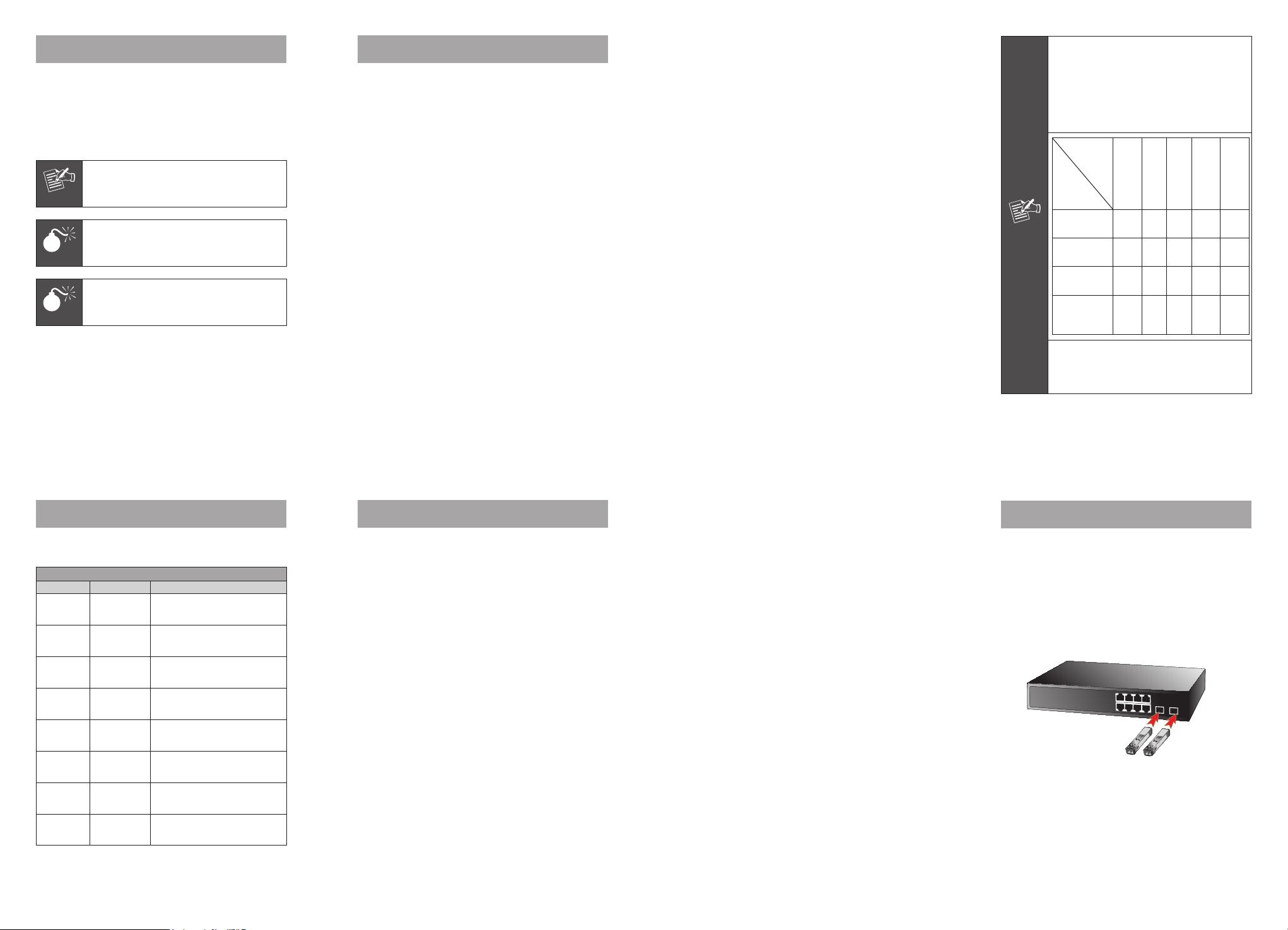
The MFB series single mode SFP
transceivers provide the optical power
budget from 15 dB to 30dB. When shorter
distance of single-mode fiber cables is
used, you might need to insert an inline optical attenuator in the link to avoid
overloading the transceiver:
SFP Model
In-line
Optical
Attenuator
Optical power
budget
Fiber Cable
Length = 10Km
Fiber Cable
Length = 30Km
15Km ≤ Fiber
Cable Length <
40Km
1. “---” means no need to use in-line
optical attenuator.
2. “X” means fiber connection not estab
lished.
MFBF20
MFB-
MFB-
MFB-
MFB-
F40
F60
FA20
TF20
24 dB30
15 dB
--- ---
X --- --- X X
--- --- --- --- ---
dB
10
dB
18 dB 18 dB
--- ---
MFBFB20
-
- 1 -
1. Model List
Your MFB family SFP Fast Ethernet module comes with
one of the following models.
Fast Ethernet SFP Module List
Model Interface Fiber connector and distance
MFB-FX
MFB-F20
MFB-F40
MFB-F60
MFB-FA20
MFB-FB20
MFB-TFX
MFB-TF20
* Models with last two numbered characters indicate the
maximum distance in km.
SFP-Port
100Base-FX
Module
SFP-Port
100Base-FX
Module
SFP-Port
100Base-FX
Module
SFP-Port
100Base-FX
Module
SFP-Port
100Base-BX
Module
SFP-Port
100Base-BX
Module
SFP-Port
100Base-FX
Module
SFP-Port
100Base-FX
Module
LC, Multi-Mode (1310nm)
-2km
LC, Single Mode (1310nm)
–20km
LC, Single Mode (1310nm)
–40km
LC, Single Mode (1310nm)
–60km
LC WDM, Single Mode
(TX: 1310nm, RX: 1550nm)
-20km
LC WDM, Single Mode
(TX: 1550nm, RX: 1310nm)
-20km
LC, Multi-Mode (1310nm)
-2km (-40~75°C)
LC, Single Mode (1310nm)
–20km (-40~75°C)
- 3 -
3. Introduction
3-1 1-Port 100Base-FX SFP Modules –
MFB-FX / MFB-F20 / MFB-F40 / MFB-F60
Features:
Comply with IEEE 802.3u Fast Ethernet standard
l
1 x 100Mbps LC ber port
l
Plug and Play Installation
l
0 to 50 Degree C operation temperature
l
- 5 -
3-3 1-Port 100Base-FX SFP Modules –
MFB-TFX / MFB-TF20
Features:
Comply with IEEE 802.3u Fast Ethernet standard
l
1 x 100Mbps LC ber port
l
Plug and Play Installation
l
-40 to 75 Degree C operation temperature
l
- 7 -
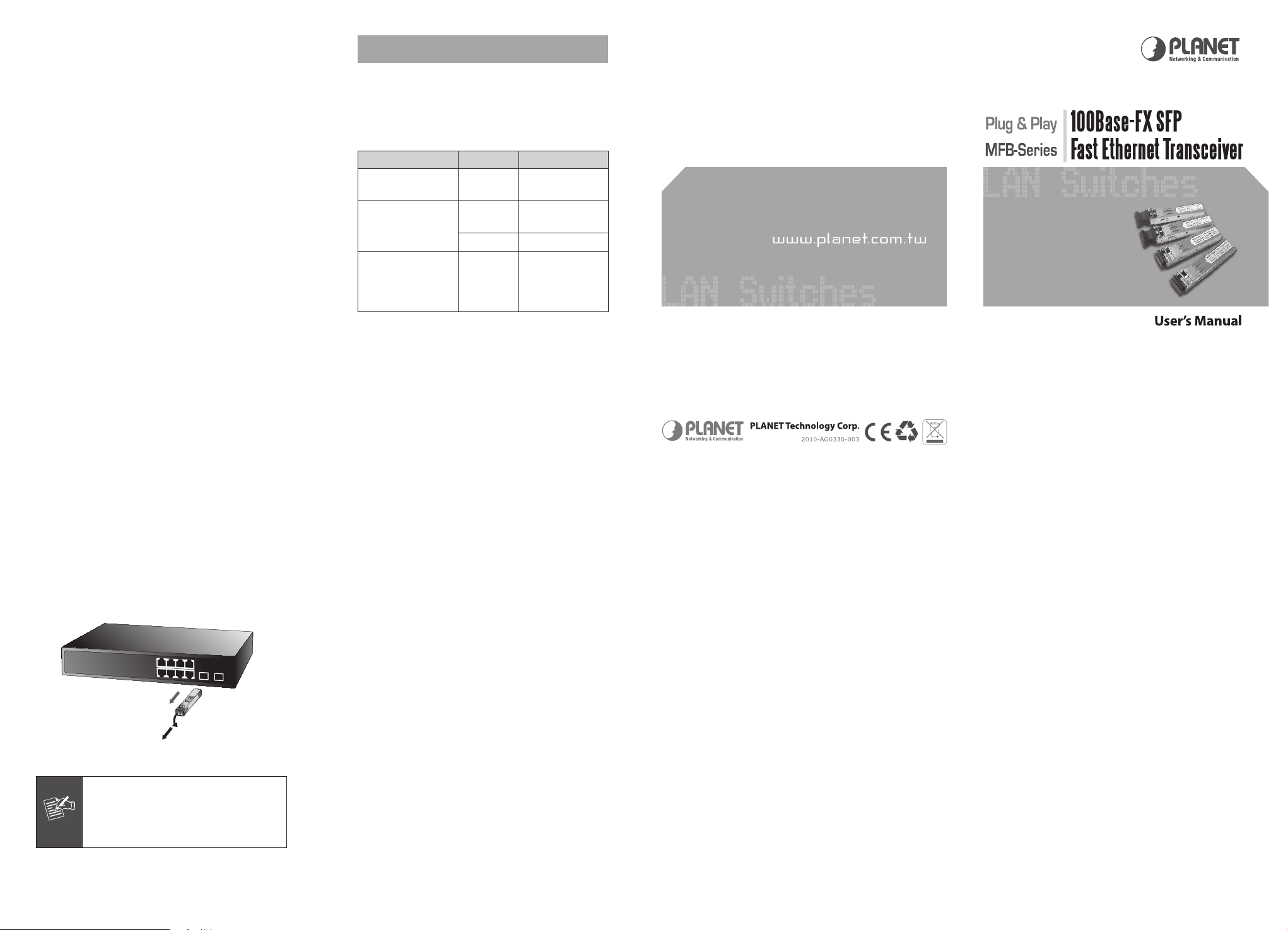
4. Installing SFP Modules
4.1 Installing the SFP transceiver
The sections describe how to insert an SFP transceiver
into an SFP slot.
The SFP transceivers are hot-pluggable and hotswappable. You can plug-in and out the transceiver to/
from any SFP port without having to power down the
Switch/Media Converter. As the Figure -1 appears.
Figure 1 Plug-in the SFP transceiver
- 2 -
- 4 -
- 6 -
- 8 -
Page 2
Before connect the other switches, workstation or
MFB
1
2
Note
Media Converter.
1. Make sure both side of the SFP transceiver are with
the same media type or WDM pair, for example:
100Base-FX to 100Base-FX, 100Base-BX20-U to
100Base-BX20-D.
2. Check the ber-optic cable type match the SFP trans
ceiver model.
l
To connect to
use the multi-mode ber cable- with one side
must be male duplex LC connector type.
l
To connect to
FB20 SFP transceiver, use the single-mode
ber cable-with one side must be male duplex LC
connector type.
Connect the ber cable
1. Attach the duplex LC connector on the network cable
into the SFP transceiver.
2. Connect the other end of the cable to a device –
switches with SFP installed, ber NIC on a workstation or a Media Converter.
3. Check the LNK/ACT LED of the SFP slot of the switch
/ converter. Ensure that the SFP transceiver is operating correctly.
4. Check the Link mode of the SFP port if the link failed.
Co works with some ber-NICs or Media Converters,
set the Link mode to “100 Force” is needed.
MFB-FX / MFB-TFX SFP transceiver,
MFB-F20/TF20/F40/F60/FA20/
APPENDIX A
A.1 Fiber Optical Cable Connection
Parameters
-
The wiring details are as below:
n Fiber Optical patch Cables:
Standard Fiber Type Cable Specication
100Base-FX
(1310nm)
100Base-FX
(1310nm)
100Base-BX-U
(TX: 1310/RX: 1550)
100Base-BX-D
(TX: 1550/RX: 1310)
Multi-mode
Multi-mode
Single-mode 9/125μm
Single-mode 9/125μm
50/125μm or
62.5/125μm
50/125μm or
62.5/125μm
- 9 -
4.2 Remove the module
1. Make sure there is no network activity by consult
or check with the network administrator. Or through
the management interface of the switch/converter (if
available) to disable the port in advance.
2. Remove the Fiber Optic Cable gently.
3. Turn the handle of the MFB module to horizontal.
4. Pull out the module gently through the handle.
Figure-2 Pull Out the SFP transceiver
Never pull out the module without pull the
handle or the push bolts on the module.
Direct pull out the module with violent
could damage the module and SFP module
slot of the device.
- 11 -
- 10 -
 Loading...