

Page 1

Before starting up and using this appliance, read and
keep this manual.
INSTRUCTION MANUAL FOR:
- INSTALLATION
- USE
- MAINTENANCE
GAS BARBECUE-GRILL
GB
Läs dessa instruktioner innan du tar grillen i bruk, och
spara bruksanvisningen för framtida bruk.
INSTRUKTIONER FÖR:
- INSTALLATION
- DRIFT
- UNDERHÅLL
GASGRILL
SE
Alvorens het apparaat in bedrijf te stellen en te
gebruiken, dient men deze handleiding door te lezen en
vervolgens goed te bewaren.
HANDLEIDING VOOR:
- DE INSTALLATIE
- HET GEBRUIK
- HET ONDERHOUD
GASBARBECUE
NL
Lesen Sie aufmerksam die Gebrauchsanweisungen,
bevor Sie das Gerät in Betrieb nehmen, und bewahren
Sie dieselben gut auf.
- INSTALLATIONS-,
- GEBRAUCHS-
- UND
INSTANDHALTUNGSANWEISUNGEN
GAS - BRATROST
DE
Lire attentivement ce manuel avant la mise en service et
l'utilisation de d'appareil. Le conserver soigneusement.
MANUEL D'INSTRUCTIONS POUR:
- L'INSTALLATION
- L'EMPLOI
- LA MAINTENANCE
BARBECUE-GRIL À GAZ
FR BE
Før apparatet blir tatt i bruk må man lese denne
bruksanvisningen nøye, og ta godt vare på den.
ANVISNING FOR:
- INSTALLASJON
- BRUK
- OG VEDLIKEHOLD
FOR GASSDREVET BBQ/GRILL
NO
Prima della messa in servizio e utilizzo dell'apparecchio,
leggere e conservare il presente manuale.
IT
MANUALE ISTRUZIONI PER:
- L'INSTALLAZIONE
- L'USO
- LA MANUTENZIONE
BARBECUE-GRILL A GAS
Lue käyttöohjeet huolellisesti ennen laitteen asennusta tai
käyttöönottoa. Säilytä käyttöopas huolellisesti vastaisen
varalle.
KÄYTTÖHJEET:
- ASENNUKSEEN
- KÄYTTÖÖN
- HUOLTOON
KAASUKÄYTTÖINEN GRILLI
FI
Antes de poner en funcionamiento y utilizar el aparato,
lea y ponga a buen recaudo este manual.
MANUAL DE INSTRUCCIONES PARA:
- INSTALACIÓN
- USO
- MANTENIMIENTO
BARBACOA-GRILL DE GAS
ES
Page 2

IT
INSTALLAZIONE DELL'APPARECCHIO
L'apparecchio può essere posizionato su un supporto qualsiasi rispettando le seguenti prescrizioni:
- Se il barbecue non viene posizionato sul carrello PLANET accertarsi che il piano d’appoggio abbia una resistenza alla temperatura di 120°C.
- Intorno all’apparecchio deve essere lasciato uno spazio d’aria di almeno 10 cm rispetto alle pareti laterali e 15 cm nel retro, dal quale esce aria a temperatura molto alta.
• NON METTERE IN FUNZIONE L'APPARECCHIO IN LUOGHI CHIUSI E NELLE VICINANZE DI MATERIALI INFIAMMABILI.
• TOGLIERE ASSOLUTAMENTE LA PELLICOLA ADESIVA PROTETTIVA (BIANCA) DALL'ACCIAIO.
ALLACCIAMENTO DELL'APPARECCHIO predisposto per:
A) FUNZIONAMENTO CON GAS BUTANO/PROPANO (VEDI TABELLA DATI TECNICI)
L'allacciamento dell'apparecchio deve avvenire a mezzo di:
• Bombola per campeggio d'uso comune di contenuto G.P.L. (gas liquido).
• Regolatore di pressione con taratura fissa secondo le normative nazionali vigenti, pressione di
funzionamento come riportato in targhetta.
• Tubi flessibili secondo le normative nazionali vigenti, di lunghezza adeguata (max. 1,5 m), che
permettano un montaggio senza pieghe e senza creare torsioni sul tubo d'allacciamento
dell'apparecchio.
• Spray cercafughe oppure acqua saponata per la verifica della tenuta.
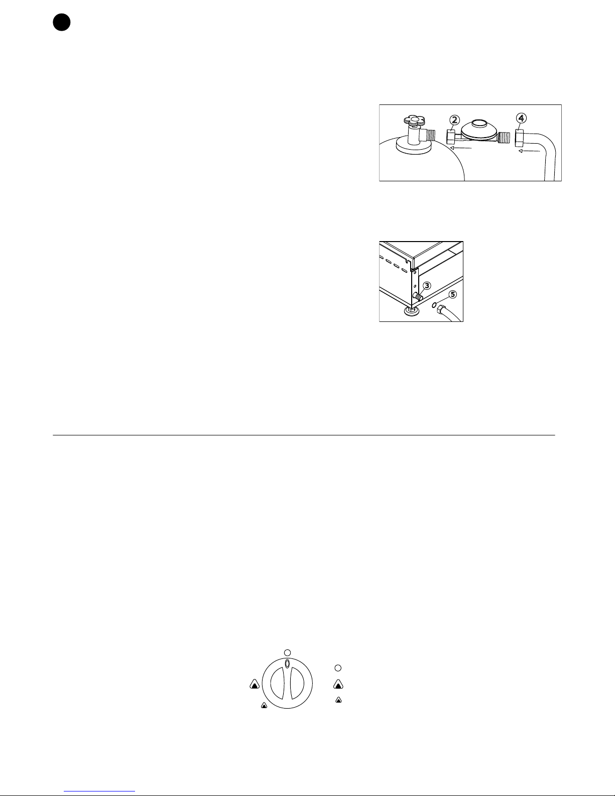
ALLACCIAMENTO DELL'APPARECCHIO ALLA BOMBOLA GAS
1) Verificare che la guarnizione del rubinetto della bombola non sia danneggiata.
2) Collegare il regolatore di pressione alla bombola (2).
3) Verificare che i rubinetti dell'apparecchio siano in posizione chiuso.
4) Raccordare il tubo al regolatore (4) se non già fissato in base alla normativa vigente, quindi il tubo
all’attacco dell’apparecchio già predisposto (3); montare correttamente la guarnizione tra il raccordo e il
portagomma stringendo il tubo con la fascetta. (5)
5) Il cambio della bombola deve essere effettuato lontano da materiale infiammabili ed all'aperto; la
bombola sostituita è da chiudere con l'apposito dado cieco e da conservare in un posto adatto.
6) Il cambio della bombola deve essere effettuato lontano da materiale infiammabili ed all'aperto; la
bombola sostituita è da chiudere con l'apposito dado cieco e da conservare in un posto adatto.
B) FUNZIONAMENTO CON GAS METANO (VEDI TABELLA DATI TECNICI)
L’allacciamento dell’apparecchio alla rete deve essere effettuato con il tubo flessibile rispondente alla
norma nazionale vigente, e va fissato all’attacco dell’apparecchio già predisposto (3); montare
correttamente la guarnizione (5) tra l’entrata della rampa e il portagomma.
VERIFICA DELLA TENUTA
La verifica della tenuta del collegamento avviene con uno spray cercafughe oppure con acqua saponata, alla pressione d'esercizio. La tenuta è considerata corretta qualora
non ci sia la formazione di bollicine.
Non controllare mai le fughe di gas con una fiamma!
ISTRUZIONI PER L'USO
• Controllare che l'apparecchio sia posizionato in modo corretto.
• Controllare che tutti i componenti siano inseriti correttamente.
• Controllare che l'allacciamento sia effettuato conformemente.
• Controllare che la bombola si trovi ad una distanza di almeno 50 cm dall'apparecchio.
• Controllare che il tubo del gas non entri in contatto con il fondo dell’apparecchio o stia in prossimità dell'uscita dell’aria calda nel retro dell'apparecchio.
ACCENSIONE
• Aprire il gas dalla bombola o dalla rete (per funzionamento a gas metano).
ACCENSIONE PIEZO ELETTRICA / ELETTRONICA
• Premere e girare contemporaneamente in senso antiorario la manopola fino alla posizione di massimo, mantenere premuta la manopola.
• Accendere il gas premendo il pulsante del piezoelettrico; dopo che il bruciatore si è acceso mantenere premuta la manopola per alcuni secondi.
• Ad accensione avvenuta, regolare la fiamma fino alla posizione di minimo.
ACCENSIONE ELETTRONICA VALVOLATA ( mod. GL/GMxxT)
• Premere e girare contemporaneamente in senso antiorario la manopola fino alla posizione di massimo, mantenere premuta la manopola per azionare l’inizio dell’accensione
elettronica.
N.B: Per la prima accensione premere la manopola per 10/15 sec. fino a quando non sia avvenuta l’accensione della fiamma.
• Dopo l’accensione del bruciatore, mantenere premuta la manopola per alcuni secondi per azionare la termocoppia.
• Il bruciatore acceso si può vedere attraverso i fori sul cruscotto; se non fosse acceso ripetere l’operazione dopo 1 minuto.
• Ad accensione avvenuta regolare la fiamma fino alla posizione di minimo.
SPEGNIMENTO
• Alla fine della cottura portare la manopola in POSIZIONE SPENTO e chiudere il rubinetto della bombola o della rete.
• Il bruciatore spento si può vedere attraverso i fori sul cruscotto.
COTTURA
• Le prime accensioni devono essere fatte con fuoco moderato, per permettere alle piastre/griglie di "stabilizzarsi".
• Non mettere a cuocere cibi congelati, non si ottiene una cottura ottimale e potrebbe provocare la deformazione del materiale piano cottura, causa shock termico.
• Tenere sotto osservazione la bacinella raccogli olio/sporco e svuotarla quando necessario, proteggendosi le mani adeguatamente (attenzione potrebbe essere molto calda).
• Non lasciare acceso l’apparecchio senza cibi da cucinare, per non portare il piano cottura a temperature molto elevate.
Questo può comportare pericolo per le persone e deformazioni nel materiale.
REGOLAZIONE DELLA FIAMMA
La fiamma può essere regolata.
Sulla manopola/cruscotto ci sono i seguenti simboli:
PULIZIA - MANUTENZIONE
- Per maggiori informazioni consultare il manuale uso e manutenzione e garanzia
- Per qualsiasi problema tecnico contattare l'assistenza tecnica.
SOSTITUZIONE PARTI DI RICAMBIO
QUESTA OPERAZIONE PUO' ESSERE ESEGUITA SOLAMENTE DA UN TECNICO SPECIALIZZATO.
Le parti che possono essere sostituite sono facili da raggiungere; è sufficiente togliere le manopole, la piastra sollevandola, quindi asportare il cruscotto svitando le viti che lo
fermano.
2
4
3
5
SPENTO
PORTATA MASSIMA
PORTATA MINIMA
IT
• BRUCIATORE: svitare la vite che lo tiene fissato, smontarlo e rimontare quello nuovo.
• CANDELA DI ACCENSIONE: Svitare la vite di fissaggio della candela e sfilare il cavo.
• RUBINETTO: togliere il portagomma sul retro, svitare il supporto/rampa, sfilare la rampa di 2 cm circa, svitare il rubinetto e sostituirlo con uno nuovo avvitandolo,
assicurandosi che sia a tenuta stagna (usare liquido bloccafiletti o teflon omologati gas).
IL COSTRUTTORE DECLINA OGNI RESPONSABILITA’ DOVUTA AD UN CATTIVO USO, AD UN USO DIVERSO DA CIO’ CHE E’ SPECIFICATO IN QUESTO MANUALE O
UN’ ERRATA INSTALLAZIONE DELL’APPARECCHIO.
PER LA VOSTRA SICUREZZA
• Prestare attenzione al modello riportato in targhetta in quanto:
• I modelli PLA-GL … sono predisposti per essere alimentati unicamente a gas BUTANO oppure a PROPANO.
• I modelli PLA-GM … sono predisposti per essere alimentati unicamente a gas METANO.
• Gli apparecchi vengono consegnati predisposti così come indicato nella targhetta tecnica posta sul retro dell’apparecchio. Una volta effettuato l’allacciamento
al gas corrispondente non è necessario nessun intervento di regolazione sull’apparecchio.
• L'apparecchio e la bombola devono essere collocati su un fondo piano e riparati dal vento facendo attenzione che nelle immediate vicinanze dell'apparecchio non vi siano
materiali infiammabili.
• Proteggere la bombola dall'irradiazione solare.
• Le bombole non possono essere conservate in casa, in posti senza ricambio d'aria, oppure in locali sotto il livello del suolo.
• ATTENZIONE: non spostare l'apparecchio, anche se provvisto di ruote, durante il funzionamento o quando è ancora caldo.
• I tubi di collegamento gas rovinati oppure porosi devono essere sostituiti, così come in caso di superamento della data di scadenza timbrata sullo stesso.
• I tubi flessibili non devono essere tirati, pizzicati oppure essere in contatto con le superfici calde.
• I lavori di manutenzione e riparazione possono essere effettuati solamente da personale autorizzato e qualificato.
• Tutte le modifiche o manomissioni possono risultare pericolose.
• Le piastre/griglie raggiungono in fase di cottura alte temperature, fare attenzione e utilizzare dei guanti protettivi.
• Non lavare e non bagnare con acqua la piastra/griglia quando è calda perché potrebbe provocare la deformazione del piano cottura.
• Si raccomanda di tenere la bombola distanziata dall'apparecchio durante l'uso.
QUESTO APPARECCHIO E' SOLAMENTE PER USO ESTERNO.
L'aria necessaria per la combustione è di 2,0 m 3 / h per ogni KW di portata termica installata (1 KW = 3412 BTU).
ATTENZIONE: LE PARTI ACCESSIBILI DELL'APPARECCHIO DURANTE IL FUNZIONAMENTO RISULTANO MOLTO CALDE PER CUI SI RACCOMANDA DI TENERE
LONTANO I BAMBINI.
SE SENTITE ODORE DI GAS:
1) Chiudete l'alimentazione del gas all'apparecchio;
2) Spegnete qualsiasi fiamma aperta;
3) Se l'odore continua rivolgetevi al vostro fornitore di gas.
CARATTERISTICHE DI COSTRUZIONE
- L'apparecchio è costruito in acciaio inossidabile.
- I bruciatori sono del tipo atmosferico.
- L'apparecchio viene consegnato completo e finito dal costruttore;non abbisogna
di montaggi particolari all'installazione.
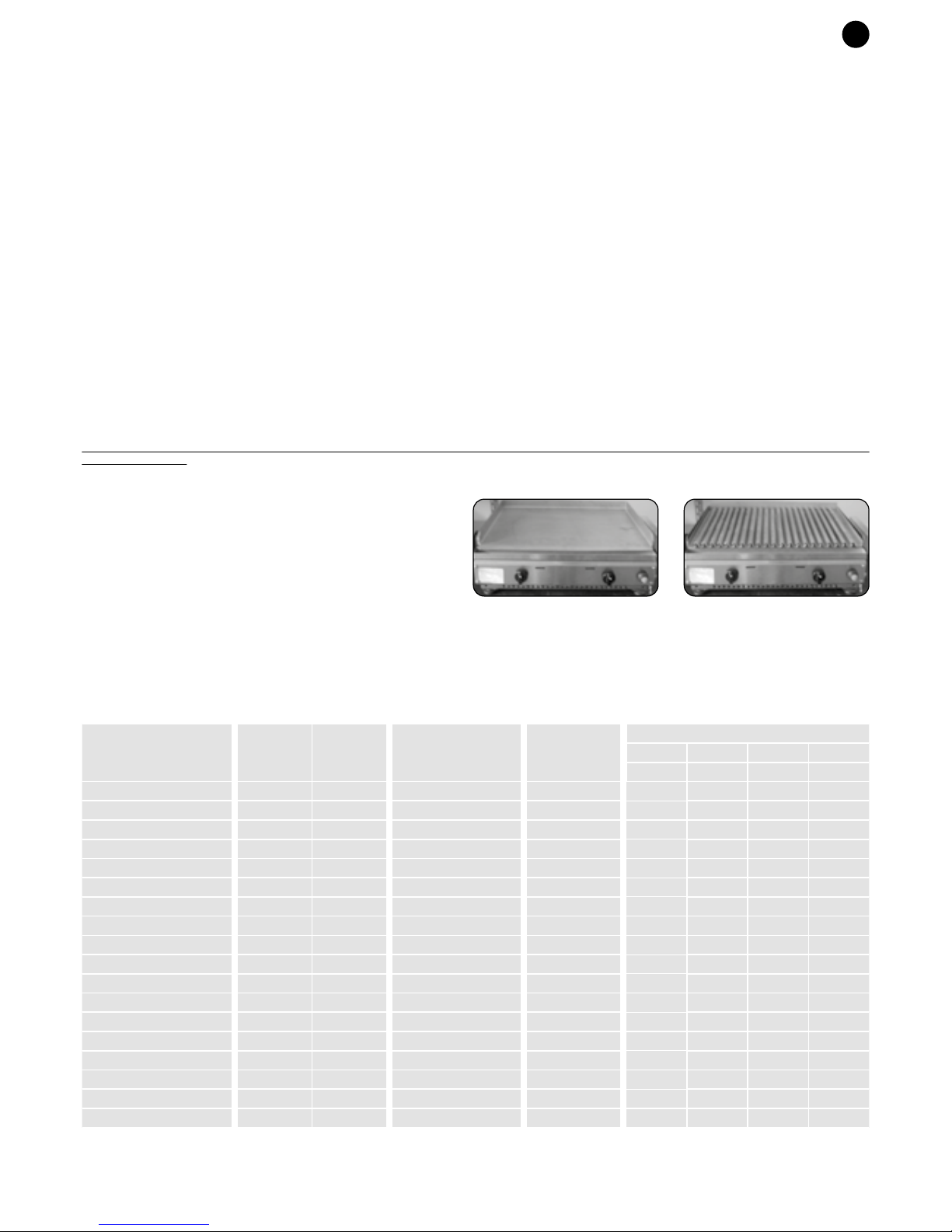
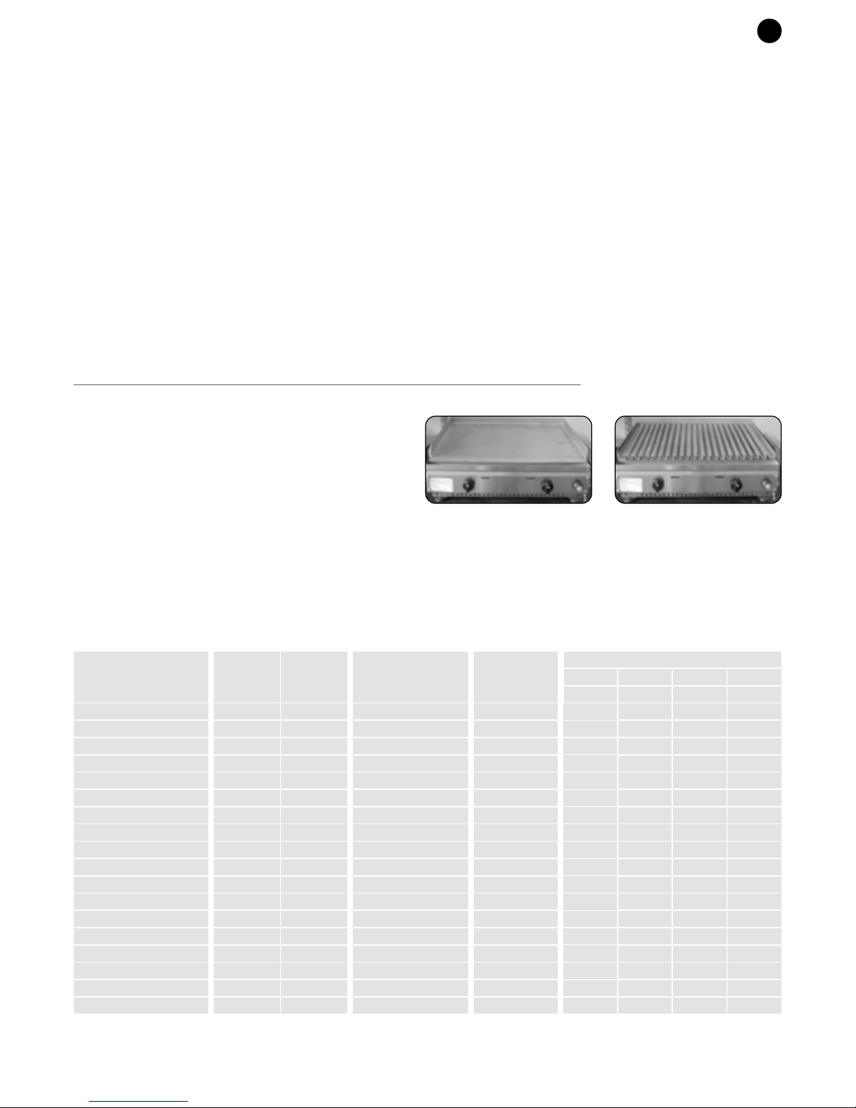
- Le versioni dell’apparecchio sono le seguenti:
Versione con piastra Fry-Top Versione con griglia pietralavica
PLA-GL40
PLA-GM40
PLA-GL40T
PLA-GM40T
PLA-GL55
PLA-GM55
PLA-GL55PL
PLA-GM55PL
PLA-GL60
PLA-GM60
PLA-GL70T
PLA-GM70T
PLA-GL80
PLA-GM80
PLA-GL80PL
PLA-GM80PL
PLA-GL26/55
PLA-GM26/55
Modello
2,8
2,8
2,8
2,8
5,6
5,6
5,6
5,6
5,6
5,6
5,6
5,6
8,4
8,4
8,4
8,4
8,4
8,4
0,267
0,267
0,534
0,534
0,534
0,534
0,800
0,800
0,800
0,310
0,310
0,620
0,620
0,620
0,620
0,931
0,931
0,931
204
204
408
408
408
408
611
611
611
200
200
400
400
400
400
600
600
600
G20
m3/h
Consumo gas
G25
m3/h
G30
g/h
G31
g/h
370 x 435 x 180
370 x 435 x 180
370 x 532 x 180
520 x 370 x 180
530 x 435 x 180
530 x 435 x 180
536 x 432 x 180
536 x 432 x 180
600 x 435 x 180
600 x 435 x 180
680 x 532 x 180
680 x 532 x 180
790 x 435 x 180
790 x 435 x 180
791 x 432 x 180
791 x 432 x 180
806 x 432 x 180
806 x 432 x 180
Nr.
bruciatori
2,8 kW
Dimensioni
L x P x H mm
Portata
termica
nominale (kW)
1
1
1
1
2
2
2
2
2
2
2
2
3
3
3
3
3
3
80
130
80
130
80
130
80
130
80
130
80
130
80
130
80
130
80
130
Ø ugello
1/100 mm
Page 3
IT
• BRUCIATORE: svitare la vite che lo tiene fissato, smontarlo e rimontare quello nuovo.
• CANDELA DI ACCENSIONE: Svitare la vite di fissaggio della candela e sfilare il cavo.
• RUBINETTO: togliere il portagomma sul retro, svitare il supporto/rampa, sfilare la rampa di 2 cm circa, svitare il rubinetto e sostituirlo con uno nuovo avvitandolo,
assicurandosi che sia a tenuta stagna (usare liquido bloccafiletti o teflon omologati gas).
IL COSTRUTTORE DECLINA OGNI RESPONSABILITA’ DOVUTA AD UN CATTIVO USO, AD UN USO DIVERSO DA CIO’ CHE E’ SPECIFICATO IN QUESTO MANUALE O
UN’ ERRATA INSTALLAZIONE DELL’APPARECCHIO.
PER LA VOSTRA SICUREZZA
• Prestare attenzione al modello riportato in targhetta in quanto:
• I modelli PLA-GL … sono predisposti per essere alimentati unicamente a gas BUTANO oppure a PROPANO.
• I modelli PLA-GM … sono predisposti per essere alimentati unicamente a gas METANO.
• Gli apparecchi vengono consegnati predisposti così come indicato nella targhetta tecnica posta sul retro dell’apparecchio. Una volta effettuato l’allacciamento
al gas corrispondente non è necessario nessun intervento di regolazione sull’apparecchio.
• L'apparecchio e la bombola devono essere collocati su un fondo piano e riparati dal vento facendo attenzione che nelle immediate vicinanze dell'apparecchio non vi siano
materiali infiammabili.
• Proteggere la bombola dall'irradiazione solare.
• Le bombole non possono essere conservate in casa, in posti senza ricambio d'aria, oppure in locali sotto il livello del suolo.
• ATTENZIONE: non spostare l'apparecchio, anche se provvisto di ruote, durante il funzionamento o quando è ancora caldo.
• I tubi di collegamento gas rovinati oppure porosi devono essere sostituiti, così come in caso di superamento della data di scadenza timbrata sullo stesso.
• I tubi flessibili non devono essere tirati, pizzicati oppure essere in contatto con le superfici calde.
• I lavori di manutenzione e riparazione possono essere effettuati solamente da personale autorizzato e qualificato.
• Tutte le modifiche o manomissioni possono risultare pericolose.
• Le piastre/griglie raggiungono in fase di cottura alte temperature, fare attenzione e utilizzare dei guanti protettivi.
• Non lavare e non bagnare con acqua la piastra/griglia quando è calda perché potrebbe provocare la deformazione del piano cottura.
• Si raccomanda di tenere la bombola distanziata dall'apparecchio durante l'uso.
QUESTO APPARECCHIO E' SOLAMENTE PER USO ESTERNO.
L'aria necessaria per la combustione è di 2,0 m 3 / h per ogni KW di portata termica installata (1 KW = 3412 BTU).
ATTENZIONE: LE PARTI ACCESSIBILI DELL'APPARECCHIO DURANTE IL FUNZIONAMENTO RISULTANO MOLTO CALDE PER CUI SI RACCOMANDA DI TENERE
LONTANO I BAMBINI.
SE SENTITE ODORE DI GAS:
1) Chiudete l'alimentazione del gas all'apparecchio;
2) Spegnete qualsiasi fiamma aperta;
3) Se l'odore continua rivolgetevi al vostro fornitore di gas.
CARATTERISTICHE DI COSTRUZIONE
- L'apparecchio è costruito in acciaio inossidabile.
- I bruciatori sono del tipo atmosferico.
- L'apparecchio viene consegnato completo e finito dal costruttore;non abbisogna
di montaggi particolari all'installazione.
- Le versioni dell’apparecchio sono le seguenti:
Versione con piastra Fry-Top Versione con griglia pietralavica
PLA-GL40
PLA-GM40
PLA-GL40T
PLA-GM40T
PLA-GL55
PLA-GM55
PLA-GL55PL
PLA-GM55PL
PLA-GL60
PLA-GM60
PLA-GL70T
PLA-GM70T
PLA-GL80
PLA-GM80
PLA-GL80PL
PLA-GM80PL
PLA-GL26/55
PLA-GM26/55
Modello
2,8
2,8
2,8
2,8
5,6
5,6
5,6
5,6
5,6
5,6
5,6
5,6
8,4
8,4
8,4
8,4
8,4
8,4
0,267
0,267
0,534
0,534
0,534
0,534
0,800
0,800
0,800
0,310
0,310
0,620
0,620
0,620
0,620
0,931
0,931
0,931
204
204
408
408
408
408
611
611
611
200
200
400
400
400
400
600
600
600
G20
m3/h
Consumo gas
G25
m3/h
G30
g/h
G31
g/h
370 x 435 x 180
370 x 435 x 180
370 x 532 x 180
520 x 370 x 180
530 x 435 x 180
530 x 435 x 180
536 x 432 x 180
536 x 432 x 180
600 x 435 x 180
600 x 435 x 180
680 x 532 x 180
680 x 532 x 180
790 x 435 x 180
790 x 435 x 180
791 x 432 x 180
791 x 432 x 180
806 x 432 x 180
806 x 432 x 180
Nr.
bruciatori
2,8 kW
Dimensioni
L x P x H mm
Portata
termica
nominale (kW)
1
1
1
1
2
2
2
2
2
2
2
2
3
3
3
3
3
3
80
130
80
130
80
130
80
130
80
130
80
130
80
130
80
130
80
130
Ø ugello
1/100 mm
Page 4

GB
INSTALLING THE APPLIANCE
The appliance can be positioned on any support according to these regulations:
- If the barbecue is not fixed on a PLA.NET trolley, make sure that the support surface withstands a temperature of at least 120°C.
- Hot air is vented out of the appliance. Please leave an air gap of at least 10 cm between the appliance and the side walls and 15 cm from the back.
• DO NOT OPERATE THE APPLIANCE IN CLOSED PLACES OR NEAR INFLAMMABLE MATERIALS.
• THE PROTECTIVE ADHESIVE FILM (WHITE) ABSOLUTELY MUST BE REMOVED FROM THE STEEL.
APPLIANCE CONNECTIONS for:
(A) BUTANE/PROPANE GAS OPERATION (SEE TECHNICAL DATA TABLE)
Connection of the unit must take place via:
• Gas cylinder commonly used for camping containing LPG (liquid gas).
• Pressure regulator calibrated as per current national standards, with operating pressure as shown on
the data plate.
• Hoses as per current national standards, of suitable length (max. 1.5 m) to allow installation without
kinks and without twisting the unit’s connecting tube.
• Leak detection spray or soapy water to check seal.
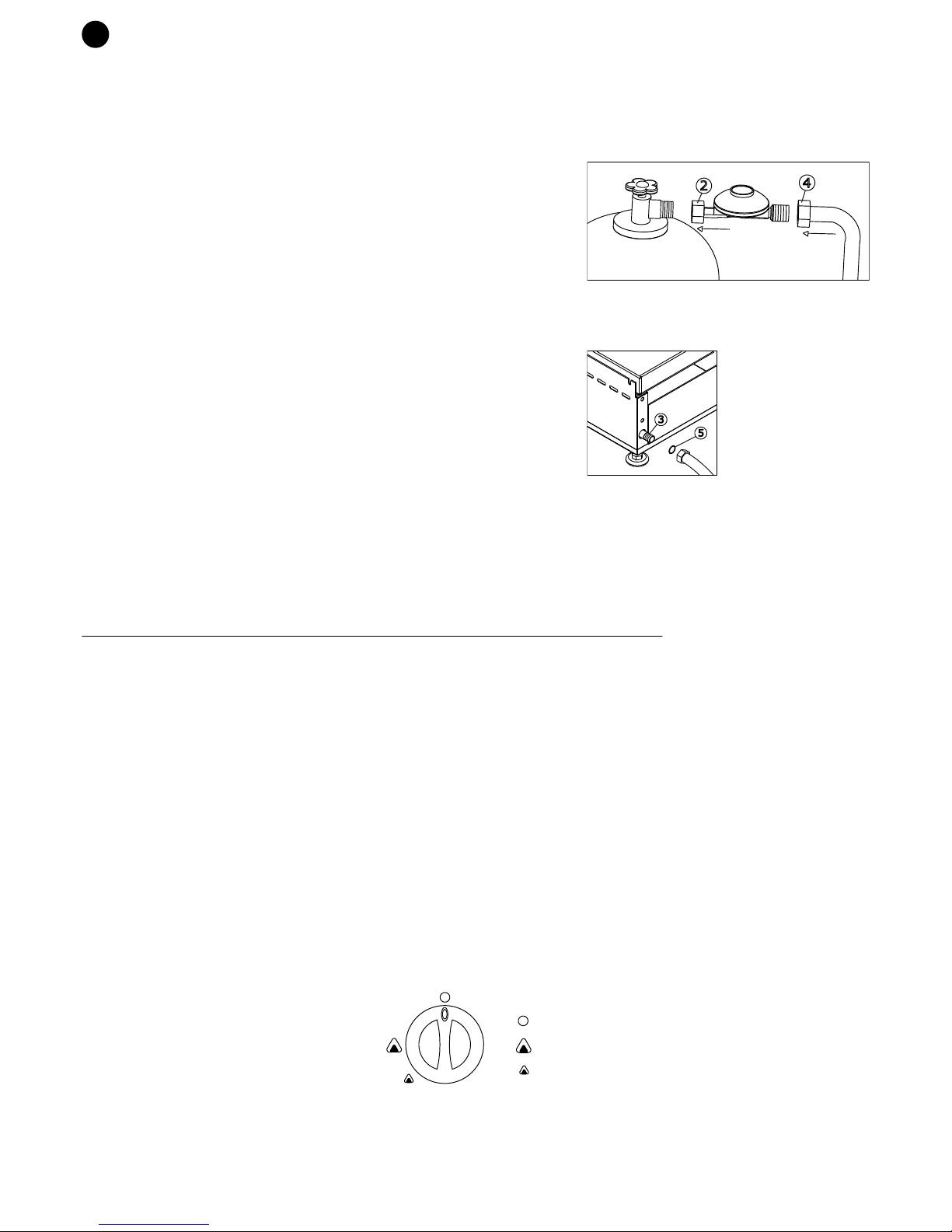
CONNECTING THE APPLIANCE TO THE GAS CYLINDER
1) Check that the seal on the gas cylinder tap is not damaged.
2) Connect the pressure regulator to the cylinder (2).
3) Check that the taps of the appliance are in the closed position.
4) Connect the pipe to the regulator (4) if not already connected according to currently enforced
regulations, assemble the seal (5) correctly between the appliance connection (3) and the hose
connector, by tightening the pipe by means of the hose clamp.
5) Place the cylinder on a flat surface. Make sure it is secured to a firm base. If the cylinder is up to 5 kg, it
may be placed on the bottom shelf of the PLA.NET trolley.
6) The cylinder must be replaced away from inflammable materials and outdoors; the replaced cylinder
must be closed with the special cap nut and kept in a suitable place.
B) METHANE GAS OPERATION (SEE TECHNICAL DATA TABLE)
When connecting the appliance to the national gas supply, ensure the flexible pipe used is in compliance
with currently enforced regulations, and that it is connected to the connection provided (3), assemble the
seal (5) correctly between the appliance connection and the hose connector.
CHECKING TIGHTNESS
Connection tightness must be checked using a gas leak detector or soapy water, at working pressure. Tightness is considered correct if bubbles do not form.
Never check gas leaks with a naked flame!
INSTRUCTIONS FOR USE
• Check that the appliance is positioned correctly.
• Check that all components are inserted correctly.
• Check that the connection is carried out according to regulations.
• Check that the cylinder is placed at a distance of at least 50cm from the appliance.
• Make sure that the gas pipe does not touch the appliance or that it is not near the hot air outlet at the back of the appliance.
START-UP
• Turn on the gas from the cylinder or the gas mains (for operation with methane gas).
PIEZO ELECTRIC / PIEZO ELECTRONIC IGNITION
• Press and turn the dial anti-clockwise, at the same time, until it is in the maximum position, keep the dial pressed down.
• Light the gas by pressing the piezoelectric button. When the burner is lit, continue to press down the dial for a few seconds.
• When it is lit you can adjust the flame to the minimum position.
ELECTRONIC IGNITION FITTED WITH VALVES ( mod.GL/GMxxT)
• Press and at the same time turn counter-clockwise the knob up to the maximum position, keep it pressed to activate the electronic trigger.
Note: For the first ignition keep the knob pressed for 10/15 seconds until the flame lights up.
• Once the burner is lit up, keep the knob pressed for a few seconds to activate the thermocouple.
• The lit burner can be seen through the holes on the control panel; if it is not lit, repeat the process after 1 minute.
• Once the device has started, adjust the flame up to the minimum position.
TURNING OFF
• When cooking is completed, turn the knob to OFF and ensure the gas tap (cylinder or main network) is tightly closed.
• The turned off burner can be seen through the holes on the control panel.
COOKING
• Use a medium flame when lighting for the first few times, to allow hotplates/grills to "stabilize".
• Do not cook frozen food. The thermal shock would lead to a deformation of the cooking top and may not guarantee optimal cooking of the food.
• Make sure you regularly check the oil/grease collecting pan and empty it when necessary. Use protective gloves (it may be very hot).
• Do not leave the appliance on without any food on it, as this would overheat the cooking top.
It may be dangerous for people and may cause deformation of the material.
ADJUSTING THE FLAME
The flame can be adjusted.
The following symbols appear on the knob/panel:
CLEANING- MAINTENANCE
- For more information, refer to the “Use and Maintenance Instructions-Planet Warranty” manual.
- If there are any technical problems, contact the technical service centre.
REPLACING SPARE PARTS
THIS OPERATION MUST ONLY BE CARRIED OUT BY A SPECIALIZED TECHNICIAN.
Parts that can be replaced are easy to reach. Simply remove the handles, lift the plate and remove the panel (by unscrewing the screws holding it in place).
2
4
3
5
OFF
MAXIMUM
MINIMUM
GB
• BURNER: loosen the screw, remove it and fasten it back again.
• SPARKING PLUG: loosen the screw that fixes the sparkling plug and remove the cable.
• TAP: Remove the rubber support on the back, loosen the support/ramp, extract the ramp by approximately 2 cm. Unscrew the tap and replace it with a new one, ensuring is
it gas tight (use a threadlocker or gas Teflon tape)
THE MANUFACTURER DENIES ANY RESPONSIBILITY DUE TO IMPROPER USE OR INCORRECT INSTALLATION OF THE APPLIANCE.
FOR YOUR SAFETY
• Note the model given on the data plate as:
• PLA-GL models are only equipped to be supplied with BUTANE or PROPANE.
• PLA-GM models are only equipped to be supplied with METHANE.
• Devices are delivered and provided as indicated in the label. Once the connection to the relative gas is completed it's not necessary perform any adjustment on
the device.
• The appliance and the cylinder must be located on a flat base and sheltered from the wind. Make sure that inflammable materials are not in the area surrounding the
appliance.
• Protect the cylinder from sunrays.
• Cylinders must not be kept in the home, in places where there is no air ventilation, or in places below ground level.
• WARNING: do not move the appliance while it is in operation or when it is still hot even if it has wheels.
• Ruined or porous gas connection pipes must be replaced, just as they should if the date stamped on them has expired.
• Flexible hoses must not be pulled, squeezed or be in contact with hot surfaces.
• Maintenance and repair work must only be carried out by authorized and qualified personnel.
• Any alterations or tampering can create a hazard.
• Hotplates/grills reach high temperatures during the cooking stage. Be careful!
• Do not wash or wet the hotplate/grill with water when it is hot, it could cause the cooking top deformation.
• Make sure you keep the cylinder away from the appliance when it is in use.
THIS APPLIANCE IS ONLY FOR OUTDOOR USE.
The air required for combustion is 2.0m 3 / h for each kW of installed thermal capacity (1 KW = 3412 BTU).
WARNING: APPLIANCE PARTS THAT ARE ACCESSIBLE DURING OPERATION ARE VERY HOT, THEREFORE WE RECOMMEND THAT CHILDREN ARE KEPT AT A
DISTANCE
IF YOU CAN SMELL GAS:
1) Shut off the gas supply to the appliance;
2) Extinguish any live flames;
3) If the smell continues, contact your gas supplier.
STRUCTURAL SPECIFICATIONS
- The appliance is made of stainless steel.
- The burners are atmospheric.
- The appliance is delivered complete and finished from the manufacturer; it does
not require special assembly when installed.
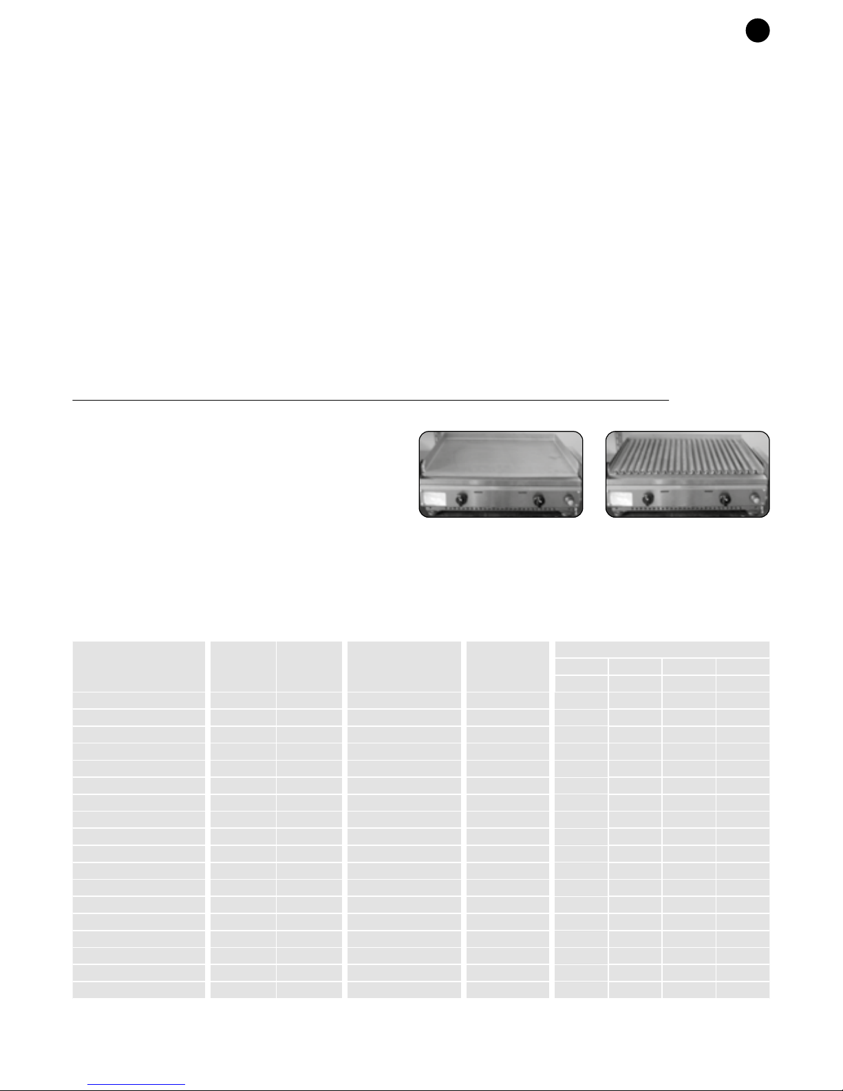
- Appliance models are as follows:
Model with Fry-Top hotplate Model with lava stone grill
PLA-GL40
PLA-GM40
PLA-GL40T
PLA-GM40T
PLA-GL55
PLA-GM55
PLA-GL55PL
PLA-GM55PL
PLA-GL60
PLA-GM60
PLA-GL70T
PLA-GM70T
PLA-GL80
PLA-GM80
PLA-GL80PL
PLA-GM80PL
PLA-GL26/55
PLA-GM26/55
Model
2,8
2,8
2,8
2,8
5,6
5,6
5,6
5,6
5,6
5,6
5,6
5,6
8,4
8,4
8,4
8,4
8,4
8,4
0,267
0,267
0,534
0,534
0,534
0,534
0,800
0,800
0,800
0,310
0,310
0,620
0,620
0,620
0,620
0,931
0,931
0,931
204
204
408
408
408
408
611
611
611
200
200
400
400
400
400
600
600
600
G20
m3/h
Consumption gas
G25
m3/h
G30
g/h
G31
g/h
370 x 435 x 180
370 x 435 x 180
370 x 532 x 180
520 x 370 x 180
530 x 435 x 180
530 x 435 x 180
536 x 432 x 180
536 x 432 x 180
600 x 435 x 180
600 x 435 x 180
680 x 532 x 180
680 x 532 x 180
790 x 435 x 180
790 x 435 x 180
791 x 432 x 180
791 x 432 x 180
806 x 432 x 180
806 x 432 x 180
N°
Burners
2,8 kW
Dimensions
W x D x H mm
Power
(kW)
1
1
1
1
2
2
2
2
2
2
2
2
3
3
3
3
3
3
80
130
80
130
80
130
80
130
80
130
80
130
80
130
80
130
80
130
Ø nozzle
1/100 mm
Page 5

GB
• BURNER: loosen the screw, remove it and fasten it back again.
• SPARKING PLUG: loosen the screw that fixes the sparkling plug and remove the cable.
• TAP: Remove the rubber support on the back, loosen the support/ramp, extract the ramp by approximately 2 cm. Unscrew the tap and replace it with a new one, ensuring is
it gas tight (use a threadlocker or gas Teflon tape)
THE MANUFACTURER DENIES ANY RESPONSIBILITY DUE TO IMPROPER USE OR INCORRECT INSTALLATION OF THE APPLIANCE.
FOR YOUR SAFETY
• Note the model given on the data plate as:
• PLA-GL models are only equipped to be supplied with BUTANE or PROPANE.
• PLA-GM models are only equipped to be supplied with METHANE.
• Devices are delivered and provided as indicated in the label. Once the connection to the relative gas is completed it's not necessary perform any adjustment on
the device.
• The appliance and the cylinder must be located on a flat base and sheltered from the wind. Make sure that inflammable materials are not in the area surrounding the
appliance.
• Protect the cylinder from sunrays.
• Cylinders must not be kept in the home, in places where there is no air ventilation, or in places below ground level.
• WARNING: do not move the appliance while it is in operation or when it is still hot even if it has wheels.
• Ruined or porous gas connection pipes must be replaced, just as they should if the date stamped on them has expired.
• Flexible hoses must not be pulled, squeezed or be in contact with hot surfaces.
• Maintenance and repair work must only be carried out by authorized and qualified personnel.
• Any alterations or tampering can create a hazard.
• Hotplates/grills reach high temperatures during the cooking stage. Be careful!
• Do not wash or wet the hotplate/grill with water when it is hot, it could cause the cooking top deformation.
• Make sure you keep the cylinder away from the appliance when it is in use.
THIS APPLIANCE IS ONLY FOR OUTDOOR USE.
The air required for combustion is 2.0m 3 / h for each kW of installed thermal capacity (1 KW = 3412 BTU).
WARNING: APPLIANCE PARTS THAT ARE ACCESSIBLE DURING OPERATION ARE VERY HOT, THEREFORE WE RECOMMEND THAT CHILDREN ARE KEPT AT A
DISTANCE
IF YOU CAN SMELL GAS:
1) Shut off the gas supply to the appliance;
2) Extinguish any live flames;
3) If the smell continues, contact your gas supplier.
STRUCTURAL SPECIFICATIONS
- The appliance is made of stainless steel.
- The burners are atmospheric.
- The appliance is delivered complete and finished from the manufacturer; it does
not require special assembly when installed.
- Appliance models are as follows:
Model with Fry-Top hotplate Model with lava stone grill
PLA-GL40
PLA-GM40
PLA-GL40T
PLA-GM40T
PLA-GL55
PLA-GM55
PLA-GL55PL
PLA-GM55PL
PLA-GL60
PLA-GM60
PLA-GL70T
PLA-GM70T
PLA-GL80
PLA-GM80
PLA-GL80PL
PLA-GM80PL
PLA-GL26/55
PLA-GM26/55
Model
2,8
2,8
2,8
2,8
5,6
5,6
5,6
5,6
5,6
5,6
5,6
5,6
8,4
8,4
8,4
8,4
8,4
8,4
0,267
0,267
0,534
0,534
0,534
0,534
0,800
0,800
0,800
0,310
0,310
0,620
0,620
0,620
0,620
0,931
0,931
0,931
204
204
408
408
408
408
611
611
611
200
200
400
400
400
400
600
600
600
G20
m3/h
Consumption gas
G25
m3/h
G30
g/h
G31
g/h
370 x 435 x 180
370 x 435 x 180
370 x 532 x 180
520 x 370 x 180
530 x 435 x 180
530 x 435 x 180
536 x 432 x 180
536 x 432 x 180
600 x 435 x 180
600 x 435 x 180
680 x 532 x 180
680 x 532 x 180
790 x 435 x 180
790 x 435 x 180
791 x 432 x 180
791 x 432 x 180
806 x 432 x 180
806 x 432 x 180
N°
Burners
2,8 kW
Dimensions
W x D x H mm
Power
(kW)
1
1
1
1
2
2
2
2
2
2
2
2
3
3
3
3
3
3
80
130
80
130
80
130
80
130
80
130
80
130
80
130
80
130
80
130
Ø nozzle
1/100 mm
Page 6
DE
GERÄTEINSTALLATION
Das Gerät kann auf jeder beliebigen Standfläche aufgestellt werden; dabei sind folgende Vorschriften einzuhalten:
- Wenn der Barbecue-Grill nicht auf einem PLANET-Wagen positioniert ist, muss man sich vergewissern, dass die Auflagefläche für eine Temperatur von 120°C geeignet ist.
- Um das Gerät herum etwas Platz freilassen: mindestens 10 cm an den Seiten und 15 cm an der Rückwand, aus der sehr heiße Luft austritt.
• SETZEN SIE DAS GERÄT NIE IN GESCHLOSSENEN RÄUMEN ODER IN DER NÄHE VON ENTFLAMMBAREM MATERIAL IN BETRIEB.
• UNBEDINGT DEN AUF DEM STAHL HAFTENDEN SCHUTZFILM (WEIß) ABZIEHEN.
ANSCHLUSS DES GERÄTS mit
(A) BUTAN-/PROPANGASBETRIEB. (SIEHE TABELLE TECHNISCHE DATEN)
muss das Gerät wie folgt angeschlossen werden:
• Normale Campinggasflasche mit G.P.L. (Flüssiggas)gefüllt.
• Druckregler mit fester Einstellung, wie von den nationalen Normen vorgeschrieben und mit auf dem
Typenschild wiedergegebenem Betriebsdruck.
• Flexible, den nationalen Normen entsprechende Rohre mit geeigneter Länge (max. 1,5 m), die eine
Montage ohne Falten und ohne Verdrehungen des Anschlußschlauches des Gerätes ermöglichen.
• Spray für Gaslecks oder Seifenwasser um die Dichtigkeit zu prüfen.
ANSCHLUSS DES GERÄTES AN DIE GASFLASCHE
1) Kontrollieren Sie, dass die Dichtung des Gasflaschenhahns in einwandfreiem Zustand ist.
2) Den Druckregler an die Gasflasche anschließen (2).
3) Vergewissern Sie sich, dass die Hähne des Gerätes geschlossen sind.
4) Das Rohr an den Regler (4) anschließen, es sei denn, es ist aufgrund der geltenden Vorschriften
bereits daran befestigt. Anschließend das Rohr mit dem bereits vorbereiteten Geräteanschluss (3)
verbinden, die Dichtung korrekt zwischen dem Anschluss und dem Schlauchhalter montieren und
den Schlauch mit der Schelle (5) befestigen
5) Die Gasflasche auf einen ebenen Boden aufstellen, nachdem man sich vergewissert hat, dass dieser
stabil ist. Gasflaschen mit einem Fassungsvermögen von maximal 5 kg Gas können auf dem unteren
Fachboden des Wagens PLA.NET positioniert werden.
6) Nehmen Sie den Austausch der Gasflasche nur im Freien und nie in der Nähe von feuergefährlichem
Material vor; verschließen Sie die leere Gasflasche mit einer Blindmutter und bewahren Sie die
Flasche an einem sicheren Ort auf.
B) ERDGASBETRIEB (SIEHE TABELLE TECHNISCHE DATEN)
Der Anschluss des Geräts an das Netz hat mit einem normengerechten Schlauch zu erfolgen. Dieser ist
an den bereits vorhandenen Anschluss (3) des Geräts anzuschließen. die Dichtung (5) korrekt zwischen
dem Rampeneingang und dem Schlauchhalter montieren.
LECKPRÜFUNG
Nehmen Sie die Dichtheitsprüfung des Anschlusses mit einem Leckprüfer - Spray oder mit Seifenwasser bei Betriebsdruck vor. Wenn sich keine Blasen bilden, kann die
Anlage als dicht angesehen werden.
Benutzen Sie zur Leckprüfung auf keinen Fall eine offene Flamme!
GEBRAUCHSANWEISUNGEN
• Kontrollieren Sie die Standfestigkeit des Gerätes.
• Vergewissern Sie sich, dass alle Bestandteile korrekt eingesetzt sind.
• Überprüfen Sie den vorschriftsmäßigen Anschluss.
• Stellen Sie sicher, dass sich die Gasflasche in einem Abstand von mindestens 50 cm vom Gerät befindet.
• Sich vergewissern, dass das Gasrohr nicht mit dem Gerät in Berührung kommt bzw. dass es sich nicht in der Nähe des Heißluftausgangs an der Geräterückseite befindet.
EINSCHALTUNG
• Drehen Sie zum Öffnen des Gashahns der Gasflasche oder des Gasnetzes (bei Erdgasbetrieb)
PIEZOELEKTRISCHE ELEKTRONISCHE ZÜNDUNG
• Drücken Sie gleichzeitig den Bedienknopf nach unten und drehen Sie denselben nach links auf die Höchststufe; halten Sie den Knopf niedergedrückt.
• Zünden Sie das Gas mit der Taste der Taktfunkenzündung an; halten Sie nach dem Zünden des Gases den Knopf noch für einige Sekunden gedrückt.
• Anschließend können Sie die Flamme auf die Mindestbrennstufe zurückdrehen.
ELEKTRONISCHE ZÜNDUNG MIT VENTIL (mod.GL/GMxxT)
• Den Knopf drücken und gleichzeitig im Uhrzeigersinn auf höchste Stufe drehen. Den Knopf gedrückt halten, um die elektronische Zündung einzuleiten.
N.B: Für die erste Zündung den Knopf 10-15 Sekunden drücken, bis die Flamme brennt.
• Nach Einschaltung des Brenners den Knopf einige Sekunden gedrückt halten, um das Thermoelement einzuschalten.
• Man kann durch die am Bedienteil angebrachten Öffnungen sehen, ob der Brenner eingeschaltet ist; sollte er nicht eingeschaltet sein, den Vorgang nach 1 Minute
wiederholen.
• Nach erfolgter Einschaltung die Flamme auf kleinste Stufe drehen.
SCHLIESSEN
• Am Ende des Kochvorgangs den Drehknopf in die OFF- POSITION drehen und den Hahn der Gasflasche bzw. des Netzes zudrehen.
• Der Brenner ist ausgeschaltet Sie durch die Löcher auf dem Armaturenbrett sehen
KOCHEN
• Das erste Anzünden darf nur mit mäßiger Flamme erfolgen, damit sich die Platten/Roste "stabilisieren" können.
• Keine tiefgekühlten Speisen kochen, da man kein gutes Kochergebnis erreichen würde. Außerdem könnte sich dadurch das Kochplattenmaterial durch den Wärmeschock verformen.
• Das Fett-/Schmutzauffangbecken regelmäßig kontrollieren und bei Bedarf leeren, wobei man sich die Hände entsprechend schützen muss (es könnte nämlich sehr heiß sein).
• Das Gerät nicht ohne Speisen eingeschaltet lassen, da die Kochplatte sonst sehr hohe Temperaturen erreichen würde. Das könnte nämlich eine Gefahr für Personen
darstellen und zu Verformungen des Materials führen.
REGULIERUNG DER FLAMME
Die Flamme kann reguliert werden.
Am Drehknopf /Bedienteil sind folgende Symbole angebracht:
REINIGUNG -INSTANDHALTUNG
- Weitere Informationen kann man der Bedienungs- und Wartungsanleitung und der Garantie entnehmen
- Wenden Sie sich für alle technischen Fragen an den Kundendienst.
AUSTAUSCH VON ERSATZTEILEN
DIESE ARBEIT DARF NUR DURCH EINE FACHKRAFT DES HERSTELLERS AUSGEFÜHRT WERDEN.
Die austauschbaren Bauteile sind leicht zugänglich. Man muss nur die Drehknöpfe entfernen und die Platte herausnehmen. Anschließend das Bedienteil entfernen, indem
man die Befestigungsschrauben ausdreht.
2
4
3
5
AUS
HÖCHSTSTUFE
MINDESTSTUFE
DE
• BRENNER: die Befestigungsschraube ausdrehen, den alten Brenner herausnehmen und den neuen Brenner befestigen.
• ZÜNDKERZE: Die Befestigungsschraube der Kerze ausdrehen und das Kabel herausziehen.
• HAHN: das Schlauchanschlussstück an der Rückseite entfernen, die Halterung/Rampe ausschrauben, die Rampe um ca. 2 cm herausziehen, den Hahn ausdrehen und mit
einem neuen Hahn auswechseln. Den neuen Hahn anschrauben und sich vergewissern, dass er dicht ist (für Gas zugelassene Gewindekleber bzw. Teflon verwenden).
DER HERSTELLER ÜBERNIMMT KEINE HAFTUNG FÜR SCHÄDEN, DIE DURCH UNSACHGEMÄSSEN GEBRAUCH ODER FALSCHE INSTALLATION
VERURSACHT SIND.SICHERHEITSHINWEISE
• Achten Sie auf das auf dem Typenschild angegebene Modell:
• Die Modelle PLA-GL … sind ausschließlich für die Verwendung mit BUTANGAS oder mit PROPANGAS.
• Die Modelle PLA-GM … dürfen ausschließlich mit ERDGAS.
• Die Geräte werden entsprechend den Angaben des Typenschilds vorgerüstet geliefert. Nach dem Anschluss an den entsprechenden Gastyp ist am Gerät keine
weitere Einstellung erforderlich.
• Stellen Sie das Gerät und die Gasflasche auf ebenem Boden an einer windgeschützten Stelle auf und vergewissern Sie sich, dass sich in unmittelbarer Nähe des Gerätes
kein feuergefährliches Material befindet.
• Schützen Sie die Gasflasche vor direkter Sonneneinstrahlung.
• Die Gasflaschen dürfen nicht in der Wohnung, in Räumen ohne Lufterneuerung oder in unterirdischen Räumlichkeiten aufbewahrt werden.
• VORSICHT: verstellen Sie das Gerät nicht während des Betriebs oder wenn es heiß ist, selbst wenn es mit Rädern versehen ist.
• Beschädigte oder poröse Gasleitungen müssen ausgewechselt werden, ebenso bei Überschreiten des auf die Schläuche aufgedruckten Verfallsdatums.
• Die Schläuche dürfen nicht straff gespannt oder eingeklemmt werden oder heiße Oberflächen berühren.
• Instandhaltungs- und Reparaturarbeiten dürfen ausschließlich von autorisierten Fachkräften ausgeführt werden.
• Es ist gefährlich, Änderungen an dem Gerät vorzunehmen.
• Die Platten/Grillroste erreichen während des Bratens hohe Temperaturen, seien Sie deshalb vorsichtig.
• Waschen Sie die heiße Platte und den heißen Rost nicht mit Wasser, da sich die Grillfläche verformen könnte.
• Das erste Anzünden darf nur mit mäßiger Flamme erfolgen, damit sich die Platten/Roste "stabilisieren" können.
• Stellen Sie die Gasflasche beim Betrieb fern vom Gerät auf.
DAS GERÄT IST AUSSCHLIESSLICH FÜR DEN GEBRAUCH IM FREIEN BESTIMMT.
Die für die Verbrennung erforderliche Luftmenge beträgt 2,0 m3 pro Stunde und für jedes KW installierter Wärmeleistung (1 KW = 3412 BTU).
ACHTUNG: DIE ZUGÄNGLICHEN GERÄTETEILE WERDEN WÄHREND DES BETRIEBS SEHR HEISS; HALTEN SIE DESHALB KINDER FERN
BEI GASGERUCH:
1) den Gashahn des Gerätes zudrehen;
2) alle offenen Flammen abstellen.
3) Verständigen Sie Ihren Gaslieferanten, wenn der Gasgeruch fortbesteht.
BAUEIGENSCHAFTEN
- Das Gerät besteht aus Edelstahl.
- Die Brenner sind atmosphärische Brenner.
- Das Gerät wird montiert und betriebsfertig geliefert und erfordert keine
besonderen Installationsarbeiten.
- Folgende Geräteausführungen sind lieferbar:
Ausführung mit Fry-Top-Platte Ausführung mit Lavastein - Rost
PLA-GL40
PLA-GM40
PLA-GL40T
PLA-GM40T
PLA-GL55
PLA-GM55
PLA-GL55PL
PLA-GM55PL
PLA-GL60
PLA-GM60
PLA-GL70T
PLA-GM70T
PLA-GL80
PLA-GM80
PLA-GL80PL
PLA-GM80PL
PLA-GL26/55
PLA-GM26/55
Modell
2,8
2,8
2,8
2,8
5,6
5,6
5,6
5,6
5,6
5,6
5,6
5,6
8,4
8,4
8,4
8,4
8,4
8,4
0,267
0,267
0,534
0,534
0,534
0,534
0,800
0,800
0,800
0,310
0,310
0,620
0,620
0,620
0,620
0,931
0,931
0,931
204
204
408
408
408
408
611
611
611
200
200
400
400
400
400
600
600
600
G20
m3/h
Verbrauch gas
G25
m3/h
G30
g/h
G31
g/h
370 x 435 x 180
370 x 435 x 180
370 x 532 x 180
520 x 370 x 180
530 x 435 x 180
530 x 435 x 180
536 x 432 x 180
536 x 432 x 180
600 x 435 x 180
600 x 435 x 180
680 x 532 x 180
680 x 532 x 180
790 x 435 x 180
790 x 435 x 180
791 x 432 x 180
791 x 432 x 180
806 x 432 x 180
806 x 432 x 180
N°
Brenner
2,8 kW
Abmessungen
L x P x H mm
Leistung
(kW)
1
1
1
1
2
2
2
2
2
2
2
2
3
3
3
3
3
3
80
130
80
130
80
130
80
130
80
130
80
130
80
130
80
130
80
130
Ø düse
1/100 mm
Page 7
DE
• BRENNER: die Befestigungsschraube ausdrehen, den alten Brenner herausnehmen und den neuen Brenner befestigen.
• ZÜNDKERZE: Die Befestigungsschraube der Kerze ausdrehen und das Kabel herausziehen.
• HAHN: das Schlauchanschlussstück an der Rückseite entfernen, die Halterung/Rampe ausschrauben, die Rampe um ca. 2 cm herausziehen, den Hahn ausdrehen und mit
einem neuen Hahn auswechseln. Den neuen Hahn anschrauben und sich vergewissern, dass er dicht ist (für Gas zugelassene Gewindekleber bzw. Teflon verwenden).
DER HERSTELLER ÜBERNIMMT KEINE HAFTUNG FÜR SCHÄDEN, DIE DURCH UNSACHGEMÄSSEN GEBRAUCH ODER FALSCHE INSTALLATION
VERURSACHT SIND.SICHERHEITSHINWEISE
• Achten Sie auf das auf dem Typenschild angegebene Modell:
• Die Modelle PLA-GL … sind ausschließlich für die Verwendung mit BUTANGAS oder mit PROPANGAS.
• Die Modelle PLA-GM … dürfen ausschließlich mit ERDGAS.
• Die Geräte werden entsprechend den Angaben des Typenschilds vorgerüstet geliefert. Nach dem Anschluss an den entsprechenden Gastyp ist am Gerät keine
weitere Einstellung erforderlich.
• Stellen Sie das Gerät und die Gasflasche auf ebenem Boden an einer windgeschützten Stelle auf und vergewissern Sie sich, dass sich in unmittelbarer Nähe des Gerätes
kein feuergefährliches Material befindet.
• Schützen Sie die Gasflasche vor direkter Sonneneinstrahlung.
• Die Gasflaschen dürfen nicht in der Wohnung, in Räumen ohne Lufterneuerung oder in unterirdischen Räumlichkeiten aufbewahrt werden.
• VORSICHT: verstellen Sie das Gerät nicht während des Betriebs oder wenn es heiß ist, selbst wenn es mit Rädern versehen ist.
• Beschädigte oder poröse Gasleitungen müssen ausgewechselt werden, ebenso bei Überschreiten des auf die Schläuche aufgedruckten Verfallsdatums.
• Die Schläuche dürfen nicht straff gespannt oder eingeklemmt werden oder heiße Oberflächen berühren.
• Instandhaltungs- und Reparaturarbeiten dürfen ausschließlich von autorisierten Fachkräften ausgeführt werden.
• Es ist gefährlich, Änderungen an dem Gerät vorzunehmen.
• Die Platten/Grillroste erreichen während des Bratens hohe Temperaturen, seien Sie deshalb vorsichtig.
• Waschen Sie die heiße Platte und den heißen Rost nicht mit Wasser, da sich die Grillfläche verformen könnte.
• Das erste Anzünden darf nur mit mäßiger Flamme erfolgen, damit sich die Platten/Roste "stabilisieren" können.
• Stellen Sie die Gasflasche beim Betrieb fern vom Gerät auf.
DAS GERÄT IST AUSSCHLIESSLICH FÜR DEN GEBRAUCH IM FREIEN BESTIMMT.
Die für die Verbrennung erforderliche Luftmenge beträgt 2,0 m3 pro Stunde und für jedes KW installierter Wärmeleistung (1 KW = 3412 BTU).
ACHTUNG: DIE ZUGÄNGLICHEN GERÄTETEILE WERDEN WÄHREND DES BETRIEBS SEHR HEISS; HALTEN SIE DESHALB KINDER FERN
BEI GASGERUCH:
1) den Gashahn des Gerätes zudrehen;
2) alle offenen Flammen abstellen.
3) Verständigen Sie Ihren Gaslieferanten, wenn der Gasgeruch fortbesteht.
BAUEIGENSCHAFTEN
- Das Gerät besteht aus Edelstahl.
- Die Brenner sind atmosphärische Brenner.
- Das Gerät wird montiert und betriebsfertig geliefert und erfordert keine
besonderen Installationsarbeiten.
- Folgende Geräteausführungen sind lieferbar:
Ausführung mit Fry-Top-Platte Ausführung mit Lavastein - Rost
PLA-GL40
PLA-GM40
PLA-GL40T
PLA-GM40T
PLA-GL55
PLA-GM55
PLA-GL55PL
PLA-GM55PL
PLA-GL60
PLA-GM60
PLA-GL70T
PLA-GM70T
PLA-GL80
PLA-GM80
PLA-GL80PL
PLA-GM80PL
PLA-GL26/55
PLA-GM26/55
Modell
2,8
2,8
2,8
2,8
5,6
5,6
5,6
5,6
5,6
5,6
5,6
5,6
8,4
8,4
8,4
8,4
8,4
8,4
0,267
0,267
0,534
0,534
0,534
0,534
0,800
0,800
0,800
0,310
0,310
0,620
0,620
0,620
0,620
0,931
0,931
0,931
204
204
408
408
408
408
611
611
611
200
200
400
400
400
400
600
600
600
G20
m3/h
Verbrauch gas
G25
m3/h
G30
g/h
G31
g/h
370 x 435 x 180
370 x 435 x 180
370 x 532 x 180
520 x 370 x 180
530 x 435 x 180
530 x 435 x 180
536 x 432 x 180
536 x 432 x 180
600 x 435 x 180
600 x 435 x 180
680 x 532 x 180
680 x 532 x 180
790 x 435 x 180
790 x 435 x 180
791 x 432 x 180
791 x 432 x 180
806 x 432 x 180
806 x 432 x 180
N°
Brenner
2,8 kW
Abmessungen
L x P x H mm
Leistung
(kW)
1
1
1
1
2
2
2
2
2
2
2
2
3
3
3
3
3
3
80
130
80
130
80
130
80
130
80
130
80
130
80
130
80
130
80
130
Ø düse
1/100 mm
Page 8
FI
LAITTEEN ASENNUS
Laite voidaan sijoittaa mille tahansa tukipinnalle, joka täyttää seuraavassa esitetyt vaatimukset:
- Mikäli grilliä ei sijoiteta PLANET vaunulle, varmista että tukipinta kestää 120°C lämpötilan.
- Jätä laitteen sivulle vähintään 10 cm ja sen taakse vähintään 15 cm vapaata tilaa (takaa poistuva ilma on erittäin kuumaa).
• ÄLÄ KÄYNNISTÄ LAITETTA SULJETUISSA TILOISSA TAI HELPOSTI SYTTYVIEN MATERIAALIEN LÄHEISYYDESSÄ.
• POISTA EHDOTTOMASTI TERÄSOSISSA OLEVA SUOJATEIPPI (VALKOINEN).
LAITTEEN KYTKENTÄ silloin, kun laitetta käytetään:
A) BUTAANI/PROPAANIKAASUJEN KANSSA (KATSO TEKNISTEN TIETOJEN TAULUKKOA)
Laitteen kytkennän on tapahduttava seuraavia laitteita käyttämällä:
• Tavallinen nestekaasulla täytetty retkikaasupullo (L.P.G.).
• Kiinteä ja asennusmaassa voimassa olevien standardien mukainen kalibroitu paineensäädin, jonka
käyttöpaine vastaa arvokyltissä mainittua arvoa.
• Asennusmaassa voimassa olevien standardien mukaiset riittävän pitkät (maks. 1,5 m)letkut, joiden
asennuksen yhteydessä laitteen liitosputki ei saa joutua kulmiin tai kierteelle.
• Ruiskuta vuotojen etsintään tarkoitettua suihketta tai saippuavettä mahdollisten vuotojen löytämiseksi.
LAITTEEN KYTKENTÄ KAASUPULLOON
1) Tarkista, ettei kaasupullon hanan tiiviste ole vahingoittunut millään tavoin.
2) Kytke paineensäädin kaasupulloon (2).
3) Tarkista, että laitteen hanat ovat suljettu- asennossa.
4) Liitä letku säätimeen (4) ellei sitä ole jo kiinnitetty voimassa olevien standardien mukaisesti ja kiinnitä
letku tämän jälkeen laitteessa jo olevaan liittimeen (3). asenna tiiviste oikein liittimen ja letkun
kannattimen väliin ja kiristä letku pinteellä (5)
5) Sijoita kaasupullo tasaiselle pinnalle ja varmista että se on vakaa. Voit sijoittaa sen myös PLA.NET
vaunun alemmalle tukitasolle siinä tapauksessa, ettei kaasupullon kapasiteetti ylitä 5 kg.
6) Älä vaihda kaasupulloa helposti syttyvän materiaalin läheisyydessä vaan ulkosalla. Sulje tyhjä
kaasupullo tarkoitukseen olevalla umpimutterilla ja säilytä pulloa tarkoitukseen soveltuvassa paikassa.
B) METAANIKAASUN KANSSA (KATSO TEKNISTEN TIETOJEN TAULUKKOA)
Kaasuverkkoon kytkentä on suoritettava asennusmaassa voimassa olevien standardien mukaista letkua
käyttämällä. Kiinnitä letku laitteessa jo olevaan liittimeen (3). asenna tiiviste (5) oikein rampin sisääntulon
ja letkun kannattimen välille.
TIIVIYDEN TARKISTUS
Tarkista liitosten tiiviys käyttöpaineessa vuotojen etsintään tarkoitettua suihketta tai saippuavettä käyttämällä. Liitokset ovat tiiviitä silloin, kun liitoskohdissa ei ilmene
ilmakuplia.
Älä tarkista kaasuvuotoja koskaan avotulia käyttämällä!
KÄYTTÖOHJEET
• Tarkista, että laite on sijoitettu oikein paikoilleen.
• Tarkista, että kaikki laitteen osat on asetettu oikein paikoilleen.
• Tarkista, että kytkennät on suoritettu lain vaatimusten mukaisesti.
• Tarkista, että kaasupullo on vähintään 50 cm etäisyydellä laitteesta.
• Varmista, ettei kaasuletku pääse koskettamaan laitetta tai älä sijoita sitä laitteen taakse, josta poistuva ilma on erittäin kuumaa.
SYTYTYS
• Aukaise kaasupullon tai kaasuverkon hana (silloin, kun laitetta käytetään metaanikaasun kanssa).
SÄHKÖISEN / ELEKTRONISEN PIETSON SYTYTYS
• Paina nuppia ja käännä sitä samanaikaisesti vastapäivään aina maksimi- asentoon saakka. Pidä nuppia painettuna.
• Sytytä kaasu painamalla sähköllä toimivaa pietsopainiketta. Pidä nuppia painettuna muutaman sekunnin ajan vielä sen jälkeenkin, kun poltin on syttynyt.
• Voit säätää liekkiä sytytyksen jälkeen aina minimiasentoon saakka.
VENTTIILEILLÄ VARUSTETTU ELEKTRONINEN SYTYTYS (malli GL/GMxxT)
• Paina ja käännä nuppia samanaikaisesti myötäpäivään, kunnes se saavuttaa maksimiasennon. Pidä nuppi painettuna, jolloin elektroninen sytytys käynnistyy.
HUOM: Paina nuppia ensimmäisen käynnistyksen yhteydessä 10/15 sek. ajan, kunnes liekki syttyy.
• Polttimen syttymisen jälkeen pidä nuppia painettuna muutaman sekunnin ajan lämpöparin käynnistämiseksi.
• Voit tarkistaa kannella olevien reikien lävitse, että poltin on syttynyt. Toista toimenpiteet 1 minuutin jälkeen, mikäli poltin ei ole syttynyt.
• Säädä liekkiä syttymisen jälkeen aina minimiasentoon saakka.
SAMMUTUS
• Aseta nuppi SULJETTU- asentoon ruoan valmistuksen jälkeen ja muista sulkea kaasupullon tai kaasuverkon hana.
• Voit tarkistaa kannella olevien reikien lävitse, että poltin on syttynyt.
RUOANVALMISTUS
• Käynnistä laite pienellä liekillä ensimmäisten käyttökertojen yhteydessä, jotta levyt/grilli pääsevät ”asettumaan" paikoilleen.
• Älä paista paistotasolla pakastettuja ja vielä jäisiä elintarvikkeita, sillä paistotulos ei ole tässä tapauksessa paras mahdollinen. Tämän lisäksi paistotason materiaali voi
vahingoittua tai vääntyä lämpöshokin vaikutuksesta.
• Pidä öljyn/lian valutusastiaa silmällä ja tyhjennä se aina tarvittaessa. Suojaa kätesi riittävän hyvin tämän toimenpiteen yhteydessä (huomio: astia voi olla erittäin kuuma).
• Älä jätä laitetta päälle pitkäksi aikaa silloin, kun sillä ei valmisteta ruokaa, sillä tässä tapauksessa paistotason lämpötila voi kohota erittäin korkealle.
• Tästä voi puolestaan seurata vaaratilanteita tai laitteen valmistusmateriaalin vääntymistä.
LIEKIN SÄÄTÄMINEN
Voit säätää liekin suuruutta.
Nupilla/etupaneelilla on seuraavat symbolit:
PUHDISTUS - HUOLTO
- Lisätietoja saat käyttö- ja huolto-oppaasta sekä takuutodistuksesta
- Ota yhteys tekniseen huoltoliikkeeseen, mikäli tarvitset teknisiä lisätietoja.
VARAOSIEN VAIHTAMINEN
NÄMÄ TOIMENPITEET SAAVAT SUORITTAA AINOASTAAN AMMATTITAITOISET VALMISTAJAN TEKNIKOT.
Voit ulottua helposti osiin, jotka voidaan vaihtaa. Irrota yksinkertaisesti nupit ja nosta tämän jälkeen levy paikaltaan. Poista etupaneeli ruuvaamalla sen kiinnitysruuvit irti.
2
4
3
5
SULJETTU
MAKS. TEHO
MIN. TEHO
FI
• POLTIN: ruuvaa sen kiinnitysruuvit irti, poista se paikaltaan ja vaihda se uuteen.
• SYTYTYSTULPPA: Löysää sytytystulpan kiinnitysruuvi ja vedä johto ulos.
• HANA: poista laitteen takana oleva letkunliitin, ruuvaa kannatin/pidike irti, vedä pidikettä ulos noin 2 cm, ruuvaa hana paikaltaan ja ruuvaa uusi hana sen tilalle. Varmista,
että liitokset ovat ilmatiiviitä (käytä kaasulle tyyppihyväksyttyjä kierretiivisteitä tai teflonia).
VALMISTAJA EI VASTAA MISTÄÄN SELLAISESTA VAHINGOSTA, JOKA JOHTUU LAITTEEN HUOLIMATTOMASTA KÄYTÖSTÄ TAI VIRHEELLISESTÄ.
ASENNUKSESTA.TURVAOHJEITA
• Tarkista arvokyltissä osoitettu malli huolellisesti, sillä:
• Mallit PLA-GL … on tarkoitettu toimimaan pelkästään BUTAANI kaasun kanssa.
• Mallit PLA-GM … on tarkoitettu toimimaan pelkästään METAANI kaasun kanssa
• Laitteet toimitetaan tyyppikilven tietojen mukaista asennusta varten. Kun vastaavan kaasutyypin kaasuliitäntä on suoritettu, laitteen säätö ei ole enää tarpeen.
• Laite ja kaasupullo on sijoitettava tasaiselle alustalle, jossa se on suojassa tuulelta. Varmista ennen kaikkea, ettei laitteen välittömässä läheisyydessä ole helposti syttyviä
materiaaleja.
• Suojaa kaasupullon auringon säteilyltä.
• Kaasupulloja ei saa säilyttää asuintiloissa, joissa ilma ei pääse kiertämään tai tiloissa, jotka ovat maanpinnan alapuolella.
• HUOMIO: Älä siirrä laitetta sen käytön aikana tai silloin, kun se on kuuma vaikka se onkin varustettu pyörillä.
• Kaasun vahingoittuneet tai huokoiset kytkentäletkut on vaihdettava välittömästi uusiin. Vaihda ne uusiin myös silloin, kun niille merkitty viimeinen käyttöpäivä kuluu umpeen.
• Älä vedä tai purista letkuja liikaa. Varmista, etteivät ne joudu kosketuksiin kuumien pintojen kanssa.
• Laitteen huoltoon ja korjaukseen liittyviä toimenpiteitä saavat suorittaa ainoastaan valtuutetut ammattihenkilöt.
• Kaiken tyyppiset laitteeseen suoritetut muutokset voivat aiheuttaa vaaratilanteita.
• Levyt/grilli saavuttavat ruoanvalmistuksen yhteydessä erittäin korkeita lämpötiloja. Ole varovainen.
• Älä pese tai kastele vedellä levyä/grilliä silloin, kun se on kuuma; silä tämä voisi aiheuttaa keittotason vääntymisen.
• Muista pitää kaasupullo kaukana itse laitteesta käytön aikana.
TÄMÄ GRILLI ON TARKOITETTU AINOASTAAN ULKOKÄYTTÖÖN.
Palamiseen tarvittavan ilman määrä on 2,0 m 3 / h jokaista asennettua lämpötehon KW varten (1 KW = 3412 BTU).
HUOMIO: USEAT LAITTEEN OSAT, JOIHIN VOIDAAN ULOTTUA HELPOSTI, MUUTTUVAT ERITTÄIN KUUMIKSI KÄYTÖN AIKANA. PIDÄ LAPSET TÄMÄN VUOKSI
KAUKANA TOIMIVAN GRILLIN LUOTA.
MIKÄLI TUNNET KAASUN HAJUA:
1) Sulje laitteeseen menevä kaasun syöttö;
2) Sammuta kaikki mahdolliset avotulet;
3) Ota yhteys kaasun jakeluyhtiöön, mikäli ongelma ei poistu.
RAKENTEELLISET OMINAISUUDET
- Laite on valmistettu ruostumattomasta teräksestä
- Laitteessa käytetyt polttimet ovat atmosfäärityyppisiä.
- Valmistaja toimittaa laitteen koottuna ja käyttövalmiina, jolloin siihen ei tarvitse
suorittaa erityisiä kokoonpanoja asennuksen yhteydessä.
- Laitteen mallit ovat seuraavat:
Fry-Top- paistotasolla varustettu malli Laavakivigrillillä varustettu malli
PLA-GL40
PLA-GM40
PLA-GL40T
PLA-GM40T
PLA-GL55
PLA-GM55
PLA-GL55PL
PLA-GM55PL
PLA-GL60
PLA-GM60
PLA-GL70T
PLA-GM70T
PLA-GL80
PLA-GM80
PLA-GL80PL
PLA-GM80PL
PLA-GL26/55
PLA-GM26/55
Malli
2,8
2,8
2,8
2,8
5,6
5,6
5,6
5,6
5,6
5,6
5,6
5,6
8,4
8,4
8,4
8,4
8,4
8,4
0,267
0,267
0,534
0,534
0,534
0,534
0,800
0,800
0,800
0,310
0,310
0,620
0,620
0,620
0,620
0,931
0,931
0,931
204
204
408
408
408
408
611
611
611
200
200
400
400
400
400
600
600
600
G20
m3/h
Kulutus gas
G25
m3/h
G30
g/h
G31
g/h
370 x 435 x 180
370 x 435 x 180
370 x 532 x 180
520 x 370 x 180
530 x 435 x 180
530 x 435 x 180
536 x 432 x 180
536 x 432 x 180
600 x 435 x 180
600 x 435 x 180
680 x 532 x 180
680 x 532 x 180
790 x 435 x 180
790 x 435 x 180
791 x 432 x 180
791 x 432 x 180
806 x 432 x 180
806 x 432 x 180
N°
Brenner
2,8 kW
Mitat
P x S x K mm
Teho
(kW)
1
1
1
1
2
2
2
2
2
2
2
2
3
3
3
3
3
3
80
130
80
130
80
130
80
130
80
130
80
130
80
130
80
130
80
130
Ø suutin
1/100 mm
Page 9

FI
• POLTIN: ruuvaa sen kiinnitysruuvit irti, poista se paikaltaan ja vaihda se uuteen.
• SYTYTYSTULPPA: Löysää sytytystulpan kiinnitysruuvi ja vedä johto ulos.
• HANA: poista laitteen takana oleva letkunliitin, ruuvaa kannatin/pidike irti, vedä pidikettä ulos noin 2 cm, ruuvaa hana paikaltaan ja ruuvaa uusi hana sen tilalle. Varmista,
että liitokset ovat ilmatiiviitä (käytä kaasulle tyyppihyväksyttyjä kierretiivisteitä tai teflonia).
VALMISTAJA EI VASTAA MISTÄÄN SELLAISESTA VAHINGOSTA, JOKA JOHTUU LAITTEEN HUOLIMATTOMASTA KÄYTÖSTÄ TAI VIRHEELLISESTÄ.
ASENNUKSESTA.TURVAOHJEITA
• Tarkista arvokyltissä osoitettu malli huolellisesti, sillä:
• Mallit PLA-GL … on tarkoitettu toimimaan pelkästään BUTAANI kaasun kanssa.
• Mallit PLA-GM … on tarkoitettu toimimaan pelkästään METAANI kaasun kanssa
• Laitteet toimitetaan tyyppikilven tietojen mukaista asennusta varten. Kun vastaavan kaasutyypin kaasuliitäntä on suoritettu, laitteen säätö ei ole enää tarpeen.
• Laite ja kaasupullo on sijoitettava tasaiselle alustalle, jossa se on suojassa tuulelta. Varmista ennen kaikkea, ettei laitteen välittömässä läheisyydessä ole helposti syttyviä
materiaaleja.
• Suojaa kaasupullon auringon säteilyltä.
• Kaasupulloja ei saa säilyttää asuintiloissa, joissa ilma ei pääse kiertämään tai tiloissa, jotka ovat maanpinnan alapuolella.
• HUOMIO: Älä siirrä laitetta sen käytön aikana tai silloin, kun se on kuuma vaikka se onkin varustettu pyörillä.
• Kaasun vahingoittuneet tai huokoiset kytkentäletkut on vaihdettava välittömästi uusiin. Vaihda ne uusiin myös silloin, kun niille merkitty viimeinen käyttöpäivä kuluu umpeen.
• Älä vedä tai purista letkuja liikaa. Varmista, etteivät ne joudu kosketuksiin kuumien pintojen kanssa.
• Laitteen huoltoon ja korjaukseen liittyviä toimenpiteitä saavat suorittaa ainoastaan valtuutetut ammattihenkilöt.
• Kaiken tyyppiset laitteeseen suoritetut muutokset voivat aiheuttaa vaaratilanteita.
• Levyt/grilli saavuttavat ruoanvalmistuksen yhteydessä erittäin korkeita lämpötiloja. Ole varovainen.
• Älä pese tai kastele vedellä levyä/grilliä silloin, kun se on kuuma; silä tämä voisi aiheuttaa keittotason vääntymisen.
• Muista pitää kaasupullo kaukana itse laitteesta käytön aikana.
TÄMÄ GRILLI ON TARKOITETTU AINOASTAAN ULKOKÄYTTÖÖN.
Palamiseen tarvittavan ilman määrä on 2,0 m 3 / h jokaista asennettua lämpötehon KW varten (1 KW = 3412 BTU).
HUOMIO: USEAT LAITTEEN OSAT, JOIHIN VOIDAAN ULOTTUA HELPOSTI, MUUTTUVAT ERITTÄIN KUUMIKSI KÄYTÖN AIKANA. PIDÄ LAPSET TÄMÄN VUOKSI
KAUKANA TOIMIVAN GRILLIN LUOTA.
MIKÄLI TUNNET KAASUN HAJUA:
1) Sulje laitteeseen menevä kaasun syöttö;
2) Sammuta kaikki mahdolliset avotulet;
3) Ota yhteys kaasun jakeluyhtiöön, mikäli ongelma ei poistu.
RAKENTEELLISET OMINAISUUDET
- Laite on valmistettu ruostumattomasta teräksestä
- Laitteessa käytetyt polttimet ovat atmosfäärityyppisiä.
- Valmistaja toimittaa laitteen koottuna ja käyttövalmiina, jolloin siihen ei tarvitse
suorittaa erityisiä kokoonpanoja asennuksen yhteydessä.
- Laitteen mallit ovat seuraavat:
Fry-Top- paistotasolla varustettu malli Laavakivigrillillä varustettu malli
PLA-GL40
PLA-GM40
PLA-GL40T
PLA-GM40T
PLA-GL55
PLA-GM55
PLA-GL55PL
PLA-GM55PL
PLA-GL60
PLA-GM60
PLA-GL70T
PLA-GM70T
PLA-GL80
PLA-GM80
PLA-GL80PL
PLA-GM80PL
PLA-GL26/55
PLA-GM26/55
Malli
2,8
2,8
2,8
2,8
5,6
5,6
5,6
5,6
5,6
5,6
5,6
5,6
8,4
8,4
8,4
8,4
8,4
8,4
0,267
0,267
0,534
0,534
0,534
0,534
0,800
0,800
0,800
0,310
0,310
0,620
0,620
0,620
0,620
0,931
0,931
0,931
204
204
408
408
408
408
611
611
611
200
200
400
400
400
400
600
600
600
G20
m3/h
Kulutus gas
G25
m3/h
G30
g/h
G31
g/h
370 x 435 x 180
370 x 435 x 180
370 x 532 x 180
520 x 370 x 180
530 x 435 x 180
530 x 435 x 180
536 x 432 x 180
536 x 432 x 180
600 x 435 x 180
600 x 435 x 180
680 x 532 x 180
680 x 532 x 180
790 x 435 x 180
790 x 435 x 180
791 x 432 x 180
791 x 432 x 180
806 x 432 x 180
806 x 432 x 180
N°
Brenner
2,8 kW
Mitat
P x S x K mm
Teho
(kW)
1
1
1
1
2
2
2
2
2
2
2
2
3
3
3
3
3
3
80
130
80
130
80
130
80
130
80
130
80
130
80
130
80
130
80
130
Ø suutin
1/100 mm
Page 10

SE
INSTALLATION
Grillen kan placeras på valfritt underlag som uppfyller följande krav:
- Om utomhusgrillen inte placeras på PLANET-vagnen, ska du försäkra dig om att stödplanet har en värmebeständighet på 120°C.
- Runt apparaten ska man lämna ett utrymme på minst 10 cm i förhållande till sidoväggarna och 15 cm till bakväggen, där luften kommer ut med en mycket hög temperatur.
• ANVÄND INTE GRILLEN I STÄNGDA UTRYMMEN ELLER I NÄRHETEN AV BRÄNNBARA MATERIAL.
• GLÖM INTE ATT TA AV DEN VITA FILMEN SOM SKYDDAR STÅLET.
ANSLUTNING AV APPARATEN som är förberedd för:
A) FUNKTION EMD BUTAN- ELLER PROPANGAS (SE TABELLEN ÖVER TEKNISKA DATA)
Anslut grillen med hjälp av:
• Vanlig gasbehållare för gasolkök med LPG-gas
• Tryckregulator med fast kalibrering enligt gällande nationella bestämmelser, med det driftstryck som
anges på märkplåten
• Slangar som uppfyller gällande nationella bestämmelser och har en längd (max. 1,5 m) som gör att de
kan monteras utan veck och utan att grillens anslutningsslang vrids.
• Läckspray eller såpvatten för att upptäcka eventuella läckor.
ANSLUTNING TILL GASBEHÅLLAREN
1) Kontrollera att behållarens kranpackning inte är skadad.
2) Anslut tryckregulatorn till behållaren (2).
3) Kontrollera att grillens kranar är stängda.
4) Anslut regulatorslangen (4) om den inte redan har satts fast enligt de gällande bestämmelserna och
därefter ansluter du slangen till fästet på apparaten som har förberetts (3). montera tätningen mellan
kopplingen och gummihållaren korrekt genom att dra åt röret med strappen(5)
5) Ställ behållaren på en plan yta och kontrollera att den är stabil. Den kan placeras på den undre skivan
på vagnen PLA.NET om behållaren har en maximal kapacitet på 5 kg gas.
6) Byt gasbehållare utomhus på avstånd från brännbart material. Stäng den gamla behållaren med
kapselmuttern och förvara den på lämplig plats.
B) FUNKTION MED METANGAS (SE TABELLEN ÖVER TEKNISKA DATA)
Apparatens nätanslutning måste utföras med en slang som överensstämmelse med de gällande
nationella normerna och den ska sättas fast vid fästet på apparaten som är förberedd för detta (3).
montera tätningen (5) korrekt mellan rampens ingång och gummihållaren.
TÄTHETSKONTROLL
Kontrollera om det finns läckor med hjälp av läckspray eller såpvatten, vid driftstryck. Att det bildas bubblor är tecken på läckage.
Kontrollera aldrig om det finns gasläckor genom att använda öppen eld!
BRUKSANVISNING
• Kontrollera att grillen är rätt placerad.
• Kontrollera att alla komponenterna är rätt isatta.
• Kontrollera att anslutningen har genomförts på rätt sätt.
• Kontrollera att gasbehållaren är placerad minst 50 cm från grillen.
• Kontrollera att gasslangen inte kommer i kontakt med apparaten eller att den är i närheten av varmluftutsläppet på apparatens baksida.
PÅSÄTTNING
• Vrid kranen för att öppna gastillförseln från behållaren eller nätet (vid metandrift).
PIEZOELEKTRISK/ELEKTRONISK PÅSÄTTNING
• Tryck in vredet och vrid det samtidigt motsols till maximiläget. Håll det intryckt.
• Tänd gasen genom att trycka på knappen på den piezoelektriska startanordningen. Håll vredet intryckt i några sekunder när brännaren har tänts.
• När lågan är tänd kan du reglera den ner till minimiläget.
ELEKTRONISK VENTILTÄNDNING ( mod. GL/GMxxT)
• Tryck och vrid samtidigt manöverratten medurs till maximal position. Håll manöverratten nedtryckt för att aktivera starten på den elektroniska tändningen.
OBS! För den första igångsättningen, ska du trycka på manöverratten i 10/15 sek. tills lågan tänds.
• Efter brännarens tändning, håll manöverratten nedtryckt i några sekunder för att aktivera det termiska paret.
• Det syns att brännaren är på genom hålen på instrumentpanelen. Om så inte är fallet, upprepa åtgärden efter 1 minut.
• Ställ in lågan på minsta läge efter påsättningen
AVSTÄNGNING
• Efter tillagningen ska du ställa ratten i STÄNGT LÄGE och stänga behållarens eller gasnätets gaskran.
• Du kan se om brännaren är tänd genom hålet i panelen.
TILLAGNING
• Använd medelhög låga de första gångerna, så att hällarna/gallren ”stabiliserar” sig.
• Tillaga inte frysta livsmedel, eftersom man inte uppnår en optiomal tillagning och kokhällens material kan deformeras, på grund av värmechocken.
• Observera olje- och smutsuppsamlingsbehållaren och töm den vid behov. Skydda händerna på lämpligt vis (var försiktig eftersom oljan kan vara mycket het).
• Låt inte apparaten vara på utan livsmedel att tillaga för att inte kokhällen ska nå mycket höga temperaturer.
Detta kan utgöra fara för personer och leda till materialdeformeringar.
INSTÄLLNING AV LÅGAN
Du kan reglera lågan.
Följande symboler sitter på ratten/instrumentbrädan:
RENGÖRING - UNDERHÅLL
- För ytterligareinformation, se drift- och underhållshandboken samt garantin
- Kontakta serviceverkstad om du får tekniska problem.
UTBYTE AV DELAR
DETTA FÅR ENDAST GÖRAS AV FACKMAN SOM HAR AUKTORISERATS AV TILLVERKAREN.
De delar som kan bytas ut är lättillgängliga. Det är tillräcklgit att avlägsna rattarna, plattan genom att lyfta den och därefter ta bort instrumentbrädan genom att skruva loss
skruvarna som håller fast den.
2
4
3
5
SLÄCKT
MAXIMUM
MINIMUM
SE
• BRÄNNARE: skruva loss skruven som håller fast den, avlägsna den och fäst den åter.
• TÄNDSTIFT: Skruva loss tändstiftets klämskruv och dra ut kabeln
• GASKRAN: ta bort gummihållaren på baksidan, skruva loss stödet/rampen, dra ut rampen cirka 2 cm, skruva loss kranen och byt ut den med en ny kran genom att skruva
fast den. Se till att installationen är tät (använd en gängblockeringsvätska eller teflon som är typgodkänd för gas).
TILLVERKAREN PÅTAR SIG INGET ANSVAR OM GRILLEN ANVÄNDS ELLER INSTALLERAS PÅ ETT FELAKTIGT SÄTT.
SÄKERHETSFÖRESKRIFTER
• Lägg märke till modelluppgiften på märkplåten:
• Modellerna PLA-GL … är förberedda för matning endast med BUTANGAS eller PROPANGAS.
• Modellerna PLA-GM … är förberedda endast för METANGAS-tillförsel.
• Apparatene leveres forhåndsinnstilt som angitt på typeskiltet. Når tilkoblingen til tilsvarende gasstype er utført, er det ikke nødvendig å foreta noen regulering
på apparatet.
• Grillen och gasbehållaren ska placeras på plant underlag och skyddade mot blåst. Se till att det inte finns brännbara material i grillens omedelbara närhet.
• Skydda gasbehållaren mot direkt solljus.
• Behållarna får inte förvaras i bostaden, på platser utan fullgod luftväxling eller i lokaler under marknivå.
• OBS: flytta inte grillen när den är igång eller när den fortfarande är varm, även om den har hjul.
• Om gasslangarna skadas eller blir otäta måste de bytas ut. Detsamma gäller när det bäst före-datum som är stämplat på dem inträder.
• Dra inte i slangarna, kläm inte ihop dem och låt dem inte komma i kontakt med heta ytor.
• Underhåll och reparationer ska utföras av auktoriserad och kvalificerad personal.
• Alla ändringar och modifieringar kan medföra fara.
• Tänk på att hällarna/gallren blir heta under tillagningen.
• Skölj inte hällen/gallret eller blöt dem med vatten när de är heta, annars kan kokhällen deformeras.
• Håll gasbehållaren på avstånd från grillen under användningen.
DENNA GRILL ÄR ENDAST AVSEDD FÖR UTOMHUSBRUK.
Den luftmängd som fordras för förbränningen är 2,0 m 3 / h för varje kW värmekapacitet (1 KW = 3412 BTU).
OBS: DE DELAR AV GRILLEN SOM ÄR ÅTKOMLIGA UNDER DRIFT BLIR MYCKET HETA. HÅLL BARN PÅ AVSTÅND.
OM DU KÄNNER GASLUKT:
1) Stäng av gastillförseln till grillen
2) Släck all öppen eld
3) Kontakta din gasleverantör om lukten inte försvinner
EGENSKAPER
- Apparaten är konstruerad av rostfritt stål.
- Brännarna är av atmosfärisk typ
- Grillen levereras komplett och färdig av tillverkaren och ingen särskild montering
fordras vid installationstillfället.
- Grillen finns i följande versioner:
Version med stekhäll Version med lavastensgaller
PLA-GL40
PLA-GM40
PLA-GL40T
PLA-GM40T
PLA-GL55
PLA-GM55
PLA-GL55PL
PLA-GM55PL
PLA-GL60
PLA-GM60
PLA-GL70T
PLA-GM70T
PLA-GL80
PLA-GM80
PLA-GL80PL
PLA-GM80PL
PLA-GL26/55
PLA-GM26/55
Modell
2,8
2,8
2,8
2,8
5,6
5,6
5,6
5,6
5,6
5,6
5,6
5,6
8,4
8,4
8,4
8,4
8,4
8,4
0,267
0,267
0,534
0,534
0,534
0,534
0,800
0,800
0,800
0,310
0,310
0,620
0,620
0,620
0,620
0,931
0,931
0,931
204
204
408
408
408
408
611
611
611
200
200
400
400
400
400
600
600
600
G20
m3/h
Förbrukning gas
G25
m3/h
G30
g/h
G31
g/h
370 x 435 x 180
370 x 435 x 180
370 x 532 x 180
520 x 370 x 180
530 x 435 x 180
530 x 435 x 180
536 x 432 x 180
536 x 432 x 180
600 x 435 x 180
600 x 435 x 180
680 x 532 x 180
680 x 532 x 180
790 x 435 x 180
790 x 435 x 180
791 x 432 x 180
791 x 432 x 180
806 x 432 x 180
806 x 432 x 180
N°
Brännare
2,8 kW
Mått
B x D x H mm
Effekt
(kW)
1
1
1
1
2
2
2
2
2
2
2
2
3
3
3
3
3
3
80
130
80
130
80
130
80
130
80
130
80
130
80
130
80
130
80
130
Ø munstycke
1/100 mm
Page 11
SE
• BRÄNNARE: skruva loss skruven som håller fast den, avlägsna den och fäst den åter.
• TÄNDSTIFT: Skruva loss tändstiftets klämskruv och dra ut kabeln
• GASKRAN: ta bort gummihållaren på baksidan, skruva loss stödet/rampen, dra ut rampen cirka 2 cm, skruva loss kranen och byt ut den med en ny kran genom att skruva
fast den. Se till att installationen är tät (använd en gängblockeringsvätska eller teflon som är typgodkänd för gas).
TILLVERKAREN PÅTAR SIG INGET ANSVAR OM GRILLEN ANVÄNDS ELLER INSTALLERAS PÅ ETT FELAKTIGT SÄTT.
SÄKERHETSFÖRESKRIFTER
• Lägg märke till modelluppgiften på märkplåten:
• Modellerna PLA-GL … är förberedda för matning endast med BUTANGAS eller PROPANGAS.
• Modellerna PLA-GM … är förberedda endast för METANGAS-tillförsel.
• Apparatene leveres forhåndsinnstilt som angitt på typeskiltet. Når tilkoblingen til tilsvarende gasstype er utført, er det ikke nødvendig å foreta noen regulering
på apparatet.
• Grillen och gasbehållaren ska placeras på plant underlag och skyddade mot blåst. Se till att det inte finns brännbara material i grillens omedelbara närhet.
• Skydda gasbehållaren mot direkt solljus.
• Behållarna får inte förvaras i bostaden, på platser utan fullgod luftväxling eller i lokaler under marknivå.
• OBS: flytta inte grillen när den är igång eller när den fortfarande är varm, även om den har hjul.
• Om gasslangarna skadas eller blir otäta måste de bytas ut. Detsamma gäller när det bäst före-datum som är stämplat på dem inträder.
• Dra inte i slangarna, kläm inte ihop dem och låt dem inte komma i kontakt med heta ytor.
• Underhåll och reparationer ska utföras av auktoriserad och kvalificerad personal.
• Alla ändringar och modifieringar kan medföra fara.
• Tänk på att hällarna/gallren blir heta under tillagningen.
• Skölj inte hällen/gallret eller blöt dem med vatten när de är heta, annars kan kokhällen deformeras.
• Håll gasbehållaren på avstånd från grillen under användningen.
DENNA GRILL ÄR ENDAST AVSEDD FÖR UTOMHUSBRUK.
Den luftmängd som fordras för förbränningen är 2,0 m 3 / h för varje kW värmekapacitet (1 KW = 3412 BTU).
OBS: DE DELAR AV GRILLEN SOM ÄR ÅTKOMLIGA UNDER DRIFT BLIR MYCKET HETA. HÅLL BARN PÅ AVSTÅND.
OM DU KÄNNER GASLUKT:
1) Stäng av gastillförseln till grillen
2) Släck all öppen eld
3) Kontakta din gasleverantör om lukten inte försvinner
EGENSKAPER
- Apparaten är konstruerad av rostfritt stål.
- Brännarna är av atmosfärisk typ
- Grillen levereras komplett och färdig av tillverkaren och ingen särskild montering
fordras vid installationstillfället.
- Grillen finns i följande versioner:
Version med stekhäll Version med lavastensgaller
PLA-GL40
PLA-GM40
PLA-GL40T
PLA-GM40T
PLA-GL55
PLA-GM55
PLA-GL55PL
PLA-GM55PL
PLA-GL60
PLA-GM60
PLA-GL70T
PLA-GM70T
PLA-GL80
PLA-GM80
PLA-GL80PL
PLA-GM80PL
PLA-GL26/55
PLA-GM26/55
Modell
2,8
2,8
2,8
2,8
5,6
5,6
5,6
5,6
5,6
5,6
5,6
5,6
8,4
8,4
8,4
8,4
8,4
8,4
0,267
0,267
0,534
0,534
0,534
0,534
0,800
0,800
0,800
0,310
0,310
0,620
0,620
0,620
0,620
0,931
0,931
0,931
204
204
408
408
408
408
611
611
611
200
200
400
400
400
400
600
600
600
G20
m3/h
Förbrukning gas
G25
m3/h
G30
g/h
G31
g/h
370 x 435 x 180
370 x 435 x 180
370 x 532 x 180
520 x 370 x 180
530 x 435 x 180
530 x 435 x 180
536 x 432 x 180
536 x 432 x 180
600 x 435 x 180
600 x 435 x 180
680 x 532 x 180
680 x 532 x 180
790 x 435 x 180
790 x 435 x 180
791 x 432 x 180
791 x 432 x 180
806 x 432 x 180
806 x 432 x 180
N°
Brännare
2,8 kW
Mått
B x D x H mm
Effekt
(kW)
1
1
1
1
2
2
2
2
2
2
2
2
3
3
3
3
3
3
80
130
80
130
80
130
80
130
80
130
80
130
80
130
80
130
80
130
Ø munstycke
1/100 mm
Page 12

FR BE
INSTALLATION DE L'APPAREIL
L'appareil peut être positionné sur un support quelconque en respectant les prescriptions suivantes :
- Si l’appareil n’est pas monté sur le chariot PLA.NET, s’assurer que la surface de support présente une résistance à une température de 120°C.
- Un espace libre doit être laissé parfaitement libre tout autour de l’appareil pour permettre à l’air de circuler ; cet espace doit être d’au moins 10 cm au niveau des parois
latérales et de 15 cm à l’arrière, d’où sort de l’air à température très élevée.
• NE PAS FAIRE FONCTIONNER L'APPAREIL DANS UN ENDROIT FERMÉ NI À PROXIMITÉ DE MATÉRIAUX INFLAMMABLES.
• ENLEVER ABSOLUMENT LA PELLICULE ADHÉSIVE DE PROTECTION (BLANCHE) DE L’ACIER.
BRANCHEMENT DE L’APPAREIL prévu pour :
A) FONCTIONNEMENT AU GAZ BUTANE/PROPANE (VOIR LE TABLEAU DONNÉES TECHNIQUES)
Le raccordement de l’appareil doit avoir lieu moyennant:
• Bouteille pour camping de commune utilisation contenant du G.P.L. (gaz liquide).
• Régulateur de pression avec réglage fixe conformément aux normes nationales en vigueur, avec
pression de fonctionnement comme reportée sur la plaquette.
• Tuyaux flexibles conformément aux normes nationales en vigueur, de longueur adéquate (max. 1,5 m), qui
permettent un montage sans plis et sans créer de torsions sur le tuyau de raccordement de l’appareil.
• Spray cherche-fuites ou bien eau savonneuse pour en contrôler l’étanchéité
RACCORDEMENT DE L'APPAREIL À LA BOUTEILLE DE GAZ
1) Vérifier que le joint du robinet de la bouteille de gaz ne soit pas endommagé.
2) Relier le régulateur de pression à la bouteille (2).
3) Vérifier que les robinets de l'appareil soient bien fermés.
4) Raccorder le tuyau au régulateur (4) s’il n’est pas déjà fixé en conformité à la réglementation en
vigueur, assembler correctement le joint (5) entre le raccord de l’appareil déjà équipé (3) et le
porte-tuyau, en serrant le tuyau avec le collier de serrage.
5) Positionner la bouteille sur un fond parfaitement plat, et vérifier qu’elle est bien stable. Elle peut être
positionnée sur l’étagère inférieure du chariot PLA.NET à condition que la bouteille ait une capacité
maximale de 5 kg de gaz.
6) Le remplacement de la bouteille de gaz doit être effectué loin de tout matériau inflammable et en plein air ;
la bouteille vide doit être fermée avec l'écrou borgne prévu à cet effet et placée dans un endroit approprié.
B) FONCTIONNEMENT AU GAZ MÉTHANE (VOIR LE TABLEAU DONNÉES TECHNIQUES)
Le branchement de l’appareil sur le réseau de distribution doit être effectué à l’aide du tuyau flexible
conforme à la norme nationale en vigueur, en le fixant soigneusement sur le raccord déjà prédisposé de
l’appareil (3), assembler correctement le joint (5) entre le raccord de l’appareil déjà équipé (3) et le
porte-tuyau.
CONTRÔLE DE L'ÉTANCHÉITÉ
Contrôler l'étanchéité du raccord à l'aide d'un aérosol pour détecter les fuites ou bien en utilisant de l'eau savonneuse, à la pression d'exercice. La tenue du raccord est
correcte s'il n'y a pas de formation de bulles d'air.
Ne jamais contrôler l'éventuelle présence de fuite de gaz au moyen d'une flamme nue !
MODE D'EMPLOI
• Vérifier que la position de l'appareil soit correcte.
• Vérifier que tous les composants soient montés correctement.
• Vérifier que le raccordement soit réalisé selon les normes en vigueur.
• Vérifier que la bouteille de gaz se trouve à au moins 50 cm de appareil.
• Contrôler que le tuyau de gaz ne touche jamais l’appareil et ne reste jamais à proximité de la sortie d’air chaud située à l’arrière de l’appareil.
MISE EN MARCHE
• Ouvrir le gaz de la bouteille ou du réseau (pour le fonctionnement au gaz méthane).
ALLUMAGE PIÉZO ÉLECTRONIQUE / ÉLECTRIQUE
• Appuyer sur la manette en la tournant simultanément dans le sens des aiguilles d'une montre jusqu'a la position de maximum, tout en maintenant la manette enfoncée.
• Allumer le gaz en appuyant sur le bouton du dispositif piézoélectrique ; une fois que le brûleur est allumé, maintenir encore la manette enfoncée pendant quelques secondes.
• Lorsque l'appareil est allumé, vous pouvez régler la flamme sur le minimum.
ALLUMAGE PIÉZO ÉLECTRONIQUE AVEC THERMOCOUPLE ( mod.GL/GMxxT)
• Appuyer et tourner en même temps, dans le sens inverse des aiguilles d’une montre, la manette jusqu’à la position de maximum, maintenir la manette enfoncée pour
actionner le débout de l’allumage électronique.
Note : Pour le première allumage, maintenir la manette enfoncée pour 10/15 secondes, jusqu’à l’allumage de la flamme
• Après que le brûleur s’est allumé, maintenir la manette enfoncée pendant quelques secondes pour actionner le thermocouple.
• On peut voir le brûleur allumé à travers des orifices situés sur le bandeau ; s’il n’est pas allumé, répéter la procédure après 1 minute.
• À allumage effectué, régler la flamme jusqu’à la position de minimum.
FERMETURE
• A la fin de la cuisson, placer la manette sur la POSITION « ÉTEINT » et refermer soigneusement le robinet de la bouteille de gaz ou du réseau.
• On peut voir le brûleur éteint à travers des orifices situés sur le bandeau.
CUISSON
• Les premiers allumages doivent rester à une température modérée afin que les plaques/grilles puissent se "stabiliser".
• Ne pas mettre d’aliments encore congelés sur la plaque de cuisson ; en effet, la cuisson ne sera jamais optimale et cette action peut provoquer la déformation du matériau
du plan de cuisson à cause du choc thermique.
• Vous pouvez voir si le brûleur est allumé à travers l'orifice situé sur le bandeau.
• Contrôler régulièrement le récipient destiné à recueillir l’huile/les déchets, et le vider chaque fois que cela est nécessaire, en prenant toujours soin de se protéger
parfaitement les mains (attention ! le récipient et son contenu risquent d’être brûlants).
• Ne jamais l’appareil allumé sans aliments à cuisiner, afin que le plan de cuisson n’atteigne pas des températures excessives qui pourraient représenter un grave danger
pour les personnes et provoquer des déformations du matériel.
RÉGULATION DE LA FLAMME
La flamme peut être réglée.
Sur la manette / tableau de bord, figurent les symboles suivants :
ENTRETIEN - MAINTENANCE
- Pour des informations complémentaires, consulter le manuel « Mode d’emploi et instructions pour la maintenance – Garantie PLA.NET
- Pour tout problème technique, contacter le service d'assistance technique.
REMPLACEMENT DE PIÈCES DÉTACHÉES
CETTE OPERATION NE DOIT ÊTRE EFFECTUÉE QUE PAR UN TECHNICIEN SPÉCIALISÉ.
Les pièces qui peuvent être remplacées sont faciles d'accès ; il suffit d’enlever les manettes, la plaque en la soulevant, puis de retirer le tableau de bord en dévissant les vis
qui le fixent.
2
4
3
5
ETEINT
DÉBIT MAXIMUM
DÉBIT MINIMUM
FR BE
• BRÛLEUR : dévisser la vis qui le fixe, le retirer, puis le fixer de nouveau.
• BOUGIE D’ALLUMAGE : dévisser la vis et extraire le câble de la bougie.
• ROBINET : retirer le porte-tuyau situé à l’arrière, dévisser le support/rampe, extraire la rampe de 2 cm environ, dévisser le robinet et le remplacer avec un robinet neuf en le
vissant, en s’assurant de sa parfaite étanchéité (utiliser un liquide bloque-filetage ou du Téflon, obligatoirement homologués pour le gaz).
LE FABRICANT DÉCLINE TOUTE RESPONSABILITÉ EN CAS D'EMPLOI INCORRECT ET/OU DE MAUVAISE INSTALLATION DE L'APPAREIL.MESURES DE SÉCURITÉ
PER LA VOSTRA SICUREZZA
• Prendre note du modèle reporté sur la plaque signalétique dans la mesure où :
• Les modèles PLA-GL … sont prédisposés pour être alimentés uniquement au gaz BUTANE ou PROPANE
• Les modèles PLA-GM … sont prédisposés pour être alimentés uniquement au gaz MÉTHANE
• Les appareils sont livrés comme indiqué sur la plaquette. Une fois que l'on a effectué le raccordement au gaz correspondant, aucune intervention de réglage
n'est nécessaire sur l'appareil.
• L'appareil et la bouteille de gaz doivent être placés sur une surface plane, à l'abri du vent, et en veillant à ce qu'aucun matériau inflammable ne se trouve à proximité de
l'unité.
• Placer la bouteille de gaz à l'abri des rayons du soleil.
• Ne pas conserver les bouteilles de gaz dans les habitations, dans les lieux non aérés, ou dans des locaux situés en sous-sol.
• ATTENZION: bien que l'appareil soit muni de roues, ne pas le déplacer pendant son fonctionnement ou lorsqu'il est encore chaud.
• Remplacer les tuyaux de gaz dès qu'ils sont usés ou poreux, ainsi que lorsque la date de péremption timbrée sur le tuyau est dépassée.
• Les tuyaux flexibles ne doivent pas être tirés, ou étranglés ni être en contact avec des surfaces chaudes.
• Les travaux d'entretien, de maintenance et les réparations ne doivent être effectués que par du personnel agréé et qualifié.
• Toute modification ou intervention sur l'appareil pourraient s'avérer dangereuses.
• En phase de cuisson, les plaques/grilles atteignent des températures très élevées - Soyez prudent.
• Ne pas laver ni mouiller la plaque/grille avec de l'eau lorsqu'elle est chaude, cela peut porter à la déformation du plan de cuisson.
• Il est recommandé de ne pas laisser la bouteille de gaz à proximité de l'appareil pendant son utilisation.
CET APPAREIL EST CONÇU EXCLUSIVEMENT POUR ÊTRE UTILISÉ À L'EXTÉRIEUR.
La quantité d'air nécessaire pour la combustion est de 2,0 m3/h pour chaque KW de portée thermique installée (1 KW = 3412 BTU).
ATTENTION : LES PARTIES DE L'APPAREIL AUXQUELLES VOUS POUVEZ ACCÉDER DEVIENNENT TRÈS CHAUDES AU COURS DU FONCTIONNEMENT, PAR
CONSÉQUENT IL EST RECOMMANDÉ DE NE PAS LAISSER DES ENFANTS S'EN APPROCHER.
SI VOUS SENTEZ UNE ODEUR DE GAZ :
1) Fermez le robinet de distribution du gaz à l'appareil ;
2) Eteignez toute flamme nue ;
3) Si l'odeur de gaz persiste, contactez votre fournisseur de gaz.s.
CARACTÉRISTIQUES DE FABRICATION
- L’appareil en objet est fabriqué en acier inoxydable.
- Les brûleurs sont du type atmosphérique.
- Le fabricant livre cet appareil l complet et fini ; l'installation ne requiertdonc
aucun montage particulier.
- L'appareil est disponible dans les versions suivantes :
Version avec plaques Fry-Top Version avec grille à pierre lavique
PLA-GL40
PLA-GM40
PLA-GL40T
PLA-GM40T
PLA-GL55
PLA-GM55
PLA-GL55PL
PLA-GM55PL
PLA-GL60
PLA-GM60
PLA-GL70T
PLA-GM70T
PLA-GL80
PLA-GM80
PLA-GL80PL
PLA-GM80PL
PLA-GL26/55
PLA-GM26/55
Modèle
2,8
2,8
2,8
2,8
5,6
5,6
5,6
5,6
5,6
5,6
5,6
5,6
8,4
8,4
8,4
8,4
8,4
8,4
0,267
0,267
0,534
0,534
0,534
0,534
0,800
0,800
0,800
0,310
0,310
0,620
0,620
0,620
0,620
0,931
0,931
0,931
204
204
408
408
408
408
611
611
611
200
200
400
400
400
400
600
600
600
G20
m3/h
Consommation gas
G25
m3/h
G30
g/h
G31
g/h
370 x 435 x 180
370 x 435 x 180
370 x 532 x 180
520 x 370 x 180
530 x 435 x 180
530 x 435 x 180
536 x 432 x 180
536 x 432 x 180
600 x 435 x 180
600 x 435 x 180
680 x 532 x 180
680 x 532 x 180
790 x 435 x 180
790 x 435 x 180
791 x 432 x 180
791 x 432 x 180
806 x 432 x 180
806 x 432 x 180
N°
Brûleurs
2,8 kW
Dimensions
L x P x H mm
Puissance
(kW)
1
1
1
1
2
2
2
2
2
2
2
2
3
3
3
3
3
3
80
130
80
130
80
130
80
130
80
130
80
130
80
130
80
130
80
130
Ø gicleur
1/100 mm
Page 13

FR BE
• BRÛLEUR : dévisser la vis qui le fixe, le retirer, puis le fixer de nouveau.
• BOUGIE D’ALLUMAGE : dévisser la vis et extraire le câble de la bougie.
• ROBINET : retirer le porte-tuyau situé à l’arrière, dévisser le support/rampe, extraire la rampe de 2 cm environ, dévisser le robinet et le remplacer avec un robinet neuf en le
vissant, en s’assurant de sa parfaite étanchéité (utiliser un liquide bloque-filetage ou du Téflon, obligatoirement homologués pour le gaz).
LE FABRICANT DÉCLINE TOUTE RESPONSABILITÉ EN CAS D'EMPLOI INCORRECT ET/OU DE MAUVAISE INSTALLATION DE L'APPAREIL.MESURES DE SÉCURITÉ
PER LA VOSTRA SICUREZZA
• Prendre note du modèle reporté sur la plaque signalétique dans la mesure où :
• Les modèles PLA-GL … sont prédisposés pour être alimentés uniquement au gaz BUTANE ou PROPANE
• Les modèles PLA-GM … sont prédisposés pour être alimentés uniquement au gaz MÉTHANE
• Les appareils sont livrés comme indiqué sur la plaquette. Une fois que l'on a effectué le raccordement au gaz correspondant, aucune intervention de réglage
n'est nécessaire sur l'appareil.
• L'appareil et la bouteille de gaz doivent être placés sur une surface plane, à l'abri du vent, et en veillant à ce qu'aucun matériau inflammable ne se trouve à proximité de
l'unité.
• Placer la bouteille de gaz à l'abri des rayons du soleil.
• Ne pas conserver les bouteilles de gaz dans les habitations, dans les lieux non aérés, ou dans des locaux situés en sous-sol.
• ATTENZION: bien que l'appareil soit muni de roues, ne pas le déplacer pendant son fonctionnement ou lorsqu'il est encore chaud.
• Remplacer les tuyaux de gaz dès qu'ils sont usés ou poreux, ainsi que lorsque la date de péremption timbrée sur le tuyau est dépassée.
• Les tuyaux flexibles ne doivent pas être tirés, ou étranglés ni être en contact avec des surfaces chaudes.
• Les travaux d'entretien, de maintenance et les réparations ne doivent être effectués que par du personnel agréé et qualifié.
• Toute modification ou intervention sur l'appareil pourraient s'avérer dangereuses.
• En phase de cuisson, les plaques/grilles atteignent des températures très élevées - Soyez prudent.
• Ne pas laver ni mouiller la plaque/grille avec de l'eau lorsqu'elle est chaude, cela peut porter à la déformation du plan de cuisson.
• Il est recommandé de ne pas laisser la bouteille de gaz à proximité de l'appareil pendant son utilisation.
CET APPAREIL EST CONÇU EXCLUSIVEMENT POUR ÊTRE UTILISÉ À L'EXTÉRIEUR.
La quantité d'air nécessaire pour la combustion est de 2,0 m3/h pour chaque KW de portée thermique installée (1 KW = 3412 BTU).
ATTENTION : LES PARTIES DE L'APPAREIL AUXQUELLES VOUS POUVEZ ACCÉDER DEVIENNENT TRÈS CHAUDES AU COURS DU FONCTIONNEMENT, PAR
CONSÉQUENT IL EST RECOMMANDÉ DE NE PAS LAISSER DES ENFANTS S'EN APPROCHER.
SI VOUS SENTEZ UNE ODEUR DE GAZ :
1) Fermez le robinet de distribution du gaz à l'appareil ;
2) Eteignez toute flamme nue ;
3) Si l'odeur de gaz persiste, contactez votre fournisseur de gaz.s.
CARACTÉRISTIQUES DE FABRICATION
- L’appareil en objet est fabriqué en acier inoxydable.
- Les brûleurs sont du type atmosphérique.
- Le fabricant livre cet appareil l complet et fini ; l'installation ne requiertdonc
aucun montage particulier.
- L'appareil est disponible dans les versions suivantes :
Version avec plaques Fry-Top Version avec grille à pierre lavique
PLA-GL40
PLA-GM40
PLA-GL40T
PLA-GM40T
PLA-GL55
PLA-GM55
PLA-GL55PL
PLA-GM55PL
PLA-GL60
PLA-GM60
PLA-GL70T
PLA-GM70T
PLA-GL80
PLA-GM80
PLA-GL80PL
PLA-GM80PL
PLA-GL26/55
PLA-GM26/55
Modèle
2,8
2,8
2,8
2,8
5,6
5,6
5,6
5,6
5,6
5,6
5,6
5,6
8,4
8,4
8,4
8,4
8,4
8,4
0,267
0,267
0,534
0,534
0,534
0,534
0,800
0,800
0,800
0,310
0,310
0,620
0,620
0,620
0,620
0,931
0,931
0,931
204
204
408
408
408
408
611
611
611
200
200
400
400
400
400
600
600
600
G20
m3/h
Consommation gas
G25
m3/h
G30
g/h
G31
g/h
370 x 435 x 180
370 x 435 x 180
370 x 532 x 180
520 x 370 x 180
530 x 435 x 180
530 x 435 x 180
536 x 432 x 180
536 x 432 x 180
600 x 435 x 180
600 x 435 x 180
680 x 532 x 180
680 x 532 x 180
790 x 435 x 180
790 x 435 x 180
791 x 432 x 180
791 x 432 x 180
806 x 432 x 180
806 x 432 x 180
N°
Brûleurs
2,8 kW
Dimensions
L x P x H mm
Puissance
(kW)
1
1
1
1
2
2
2
2
2
2
2
2
3
3
3
3
3
3
80
130
80
130
80
130
80
130
80
130
80
130
80
130
80
130
80
130
Ø gicleur
1/100 mm
Page 14

ES
INSTALACIÓN DEL APARATO
Puede ubicar el aparato sobre cualquier soporte, siempre que respete las siguientes prescripciones:
- Si la barbacoa no se coloca sobre la carretilla PLANET asegurarse de que la superficie de apoyo tenga una resistencia al calor de 120°C
- Alrededor del aparato se debe dejar un espacio de aire de al menos 10 cm con respecto a las paredes laterales y de 15 cm con respecto a la parte trasera, de la cual sale
aire a una temperatura muy alta.
• NO PONGA EN FUNCIONAMIENTO EL APARATO EN LUGARES CERRADOS NI CERCA DE MATERIALES INFLAMABLES.
• ES IMPRESCINDIBLE QUITAR LA PELÍCULA ADHESIVA DE PROTECCIÓN (BLANCA) DEL
ACERO.
CONEXIÓN DEL APARATO, con predisposición para:
A) FUNCIONAMIENTO CON GAS BUTANO/PROPANO (VER TABLA DE DATOS TÉCNICOS)
La conexión del aparato debe realizarse por medio de:
• Bombona de camping de uso común con contenido de G.P.L. (gas propano líquido).
• Regulador de presión con calibrado fijo según las normas vigentes nacionales, con presión de
funcionamiento como se muestra en la placa.
• Tubos flexibles según las normas vigentes nacionales, de longitud adecuada (más. De 1,5m), que
permitan el montaje sin pliegues y sin crear torsiones en el tubo de conexión del aparato.
• Spray para la búsqueda de escapes o agua jabonosa para comprobar la estanqueidad.
CONEXIÓN DEL APARATO A LA BOMBONA DE GAS
1) Compruebe que la guarnición de la válvula de la bombona no se encuentre dañada.
2) Conectar el regulador de presión a la bombona (2).
3) Compruebe que las válvulas del aparato se encuentren en posición cerrada.
4) Unir el tubo al regulador (4) si no ha sido ya fijado con base en la normativa vigente, luego el tubo al
enchufe ya predispuesto del aparato (3). Montar de manera adecuada la junta entre la conexión y el
conector apretando el tubo con la abrazadera de manguera (5)
5) Posicionar la bombona sobre un fondo plano, verificando que sea estable. Se puede posicionar sobre
la barra inferior de la carretilla PLA.NET si la bombona tiene una capacidad máxima de 5 kg de gas.
6) Debe proceder al cambio de la bombona lejos de materiales inflamables y al aire libre,cerrar la
bombona sustituida con una tuerca ciega y almacenarla en un lugar adecuado.
B) FUNCIONAMIENTO CON GAS METANO (G20) (VER TABLA DE DATOS TÉCNICOS)
La conexión del aparato a la red se debe realizar con el tubo flexible correspondiente a la norma nacional
vigente, y se conecta al enchufe ya predispuesto del aparato (3). montar de manera adecuada la junta
(5) entre la entrada de la rampa y el conector.
COMPROBACIÓN DE LA ESTANQUEIDAD
Debe llevar a cabo la comprobación de la estanqueidad de la conexión con un spray para detectar pérdidas o con agua jabonosa, tras presión de servicio. La estanqueidad
será correcta siempre que no se dé formación de pompas.
¡No compruebe nunca si existen escapes de gas con una llama!
INSTRUCCIONES DE USO
• Compruebe que el aparato esté colocado de forma correcta.
• Compruebe que todos los componentes se hayan montado correctamente.
• Compruebe que la conexión se haya llevado a cabo conforme a las instrucciones.
• Compruebe que la bombona se encuentre a una distancia de al menos 50 cm del aparato.
• Revisar que el tubo del gas no entre en contacto con el aparato o esté cerca de la salida del aire caliente en la parte de atrás del aparato.
ENCENDIDO
• Abra el flujo de gas desde la bombona o desde la red (para funcionamiento a gas metano).
ENCENDIDO PIEZOELÉCTRICO/ELECTRÓNICO
• Pulse y, a la vez, gire el mando en sentido contrario al de las agujas del reloj hasta la posición de máximo, mantenga pulsado el mando.
• Encienda el gas pulsando el botón del piezoeléctrico; tras el encendido del quemador, siga pulsando el mando durante algunos segundos.
• Una vez que se ha conseguido el encendido, puede regular la llama y ponerla en la posición de mínimo.
ENCENDIDO ELECTRÓNICO CON VÁLVULA (mod.GL/GMxxT)
• Presionar y girar al mismo tiempo en sentido contrario a las manecillas del reloj la perilla hasta la posición de máximo, mantener presionadala perilla para accionar el inicio
del encendido electrónico.
Nota: para el primer encendido presionar la perilla durante 10/15 s. hasta que no se encienda la llama.
• Después del encendido del quemador, mantener presionada la perilla durante algunos segundos para accionar el termopar.
• El quemador encendido se puede ver a través de los agujeros del panel; si no estuviese encendido repetir la operación después de 1 minuto.
• Una vez logrado el encendido, ajustar la llama hasta la posición de mínimo.
APAGADO
• Al final de la cocción, llevar la perilla a la POSICIÓN APAGADO y cerrar la llave de la bombona o de la red.
• El quemador apagado se puede ver a través del orificio del tablero de instrumentos.
COCINA
• Debe realizar los primeros encendidos con fuego medio, para permitir la "estabilización" de planchas y rejillas.
• No poner a cocinar alimentos congelados, ya que no se obtiene una cocción óptima y podría provocar la deformación del material de la zona de cocción, debido al choque térmico.
• El quemador encendido se puede ver a través del orificio del tablero de instrumentos.
• Tener bajo observación el tanquecito de recolección del aceite/suciedad y vaciarlo cuando sea necesario, protegiéndose las manos de manera adecuada (cuidado, ya que
podría estar muy caliente).
• No dejar el aparato encendido sin alimentos que cocinar, para evitar que la zona de cocción alcance temperaturas muy elevadas.
Esto puede suponer un peligro para las personas así como la deformación del material.
REGULACIÓN DE LA LLAMA
Es posible regular la llama.
Sobre la perilla/cuadro de mando se encuentran los siguientes símbolos:
LIMPIEZA - MANTENIMIENTO
- Para mayor información consultar el manual de uso y mantenimiento y garantía
- Para cualquier problema técnico, póngase en contacto con el servicio de asistencia técnica.
SUSTITUCIÓN PARTES RECAMBIO
ESTA OPERACIÓN SÓLO PUEDE LLEVARLA A CABO UN TÉCNICO ESPECIALIZADO.
Las partes que se puede sustituir son fáciles de alcanzar. Basta con quitar la plancha. Es suficiente quitar las perillas, la plancha alzándola, luego quitar el cuadrode mando
destornillando los tornillos que lo sujetan.
2
4
3
5
APAGADO
CAUDAL MÁXIMO
CAUDAL MÍNIMO
ES
• QUEMADOR: destornillar los tornillos que lo sujetan, quitarlo y volver a sujetar el nuevo.
• LLAMA DE ENCENDIDO: Destornillar el tornillo de fijación de la bujía y sacar el cable.
• GRIFO/LLAVE: quitar el porta goma de la parte trasera, destornillar el soporte / rampa, sacar la rampa unos 2 cm, destornillar el grifo y sustituirlo con uno nuevo
atornillándolo, asegurándose de que esté sellado (usar líquido bloca roscas o teflón homologado para gases).
EL CONSTRUCTOR RECHAZA TODA RESPONSABILIDAD DERIVADA DE UN USO INCORRECTO O DE UNA INSTALACIÓN ERRÓNEA DEL APARATO. PARA SU
SEGURIDAD
PER LA VOSTRA SICUREZZA
• Preste atención al modelo citado en la tarjeta de características técnicas, especialmente en lo que se refiere a:
• Los modelos PLA-GL … están predispuestos para ser alimentados únicamente con gas BUTANO o a PROPANO.
• Los modelos PLA-GM... están predispuestos para ser alimentados únicamente con gas METANO.
• Los aparatos se entregan con la preparación indicada en la placa. Una vez realizada la conexión del gas correspondiente, no se necesita ninguna intervención
de regulación en el aparato.
• Debe ubicar el aparato y la bombona sobre una superficie lisa y resguardados del viento, prestando atención a que no haya materiales inflamables cerca del aparato.
• Proteja la bombona de la radiación solar.
• No debe conservar las bombonas en casa, en lugares sin ventilación o en locales por debajo del nivel del suelo.
• CUIDADO: no cambie de lugar el aparato, incluso si tiene ruedas, durante su funcionamiento o si aún está caliente.
• Debe sustituir los tubos de conexión de gas dañados o si presentan poros, así como en aquellos casos en que se ha superado la fecha de caducidad impresa sobre ellos.
• No debe tirar ni pellizcar los tubos flexibles, así como no debe ponerlos en contacto con superficies calientes.
• Sólo aquellas personas autorizadas y cualificadas pueden llevar a cabo trabajos de mantenimiento y reparación.
• Cualquier modificación o alteración puede resultar peligrosa.
• Las planchas y rejillas alcanzan elevadas temperaturas durante la fase de cocción, tenga cuidado.
• No limpie ni moje con agua planchas o rejillas mientras éstas estén calientes, porque podría provocar la deformación de la superficie de cocción.
• Se recomienda que mantenga la bombona alejada del aparato durante el uso.
ESTE APARATO ES DE USO EXCLUSIVO EN EXTERIORES.
El aire necesario para la combustión es de 2,0 m 3 / h por cada KW de carga calorífica instalado (1 KW = 3412 BTU).
CUIDADO: LAS PARTES ACCESIBLES DEL APARATO DURANTE SU FUNCIONAMIENTO ALCANZAN TEMPERATURAS MUY ALTAS, POR LO QUE SE
RECOMIENDA MANTENER ALEJADOS A LOS NIÑOS
SI DETECTA OLOR A GAS:
1) Cierre la alimentación de gas del aparato;
2) Apague cualquier llama que se encuentre encendida;
3) Si el olor persiste, póngase en contacto con su suministrador de gas.
CARACTERÍSTICAS DE FABRICACIÓN
- El aparato está construido en acero inoxidable.
- Los quemadores son de tipo atmosférico.
- El aparato se suministra completo y acabado por el constructor. No necesita de
ninguna clase de montaje durante su instalación.
- Las versiones del aparato son las siguientes:
Versión con plancha Fry-Top Versión con rejilla de piedra lávica
PLA-GL40
PLA-GM40
PLA-GL40T
PLA-GM40T
PLA-GL55
PLA-GM55
PLA-GL55PL
PLA-GM55PL
PLA-GL60
PLA-GM60
PLA-GL70T
PLA-GM70T
PLA-GL80
PLA-GM80
PLA-GL80PL
PLA-GM80PL
PLA-GL26/55
PLA-GM26/55
Modelo
2,8
2,8
2,8
2,8
5,6
5,6
5,6
5,6
5,6
5,6
5,6
5,6
8,4
8,4
8,4
8,4
8,4
8,4
0,267
0,267
0,534
0,534
0,534
0,534
0,800
0,800
0,800
0,310
0,310
0,620
0,620
0,620
0,620
0,931
0,931
0,931
204
204
408
408
408
408
611
611
611
200
200
400
400
400
400
600
600
600
G20
m3/h
Consumo gas
G25
m3/h
G30
g/h
G31
g/h
370 x 435 x 180
370 x 435 x 180
370 x 532 x 180
520 x 370 x 180
530 x 435 x 180
530 x 435 x 180
536 x 432 x 180
536 x 432 x 180
600 x 435 x 180
600 x 435 x 180
680 x 532 x 180
680 x 532 x 180
790 x 435 x 180
790 x 435 x 180
791 x 432 x 180
791 x 432 x 180
806 x 432 x 180
806 x 432 x 180
N°
Quemadores
2,8 kW
Medidas
L x P x H mm
Potencia
(kW)
1
1
1
1
2
2
2
2
2
2
2
2
3
3
3
3
3
3
80
130
80
130
80
130
80
130
80
130
80
130
80
130
80
130
80
130
Ø tobera
1/100 mm
Page 15
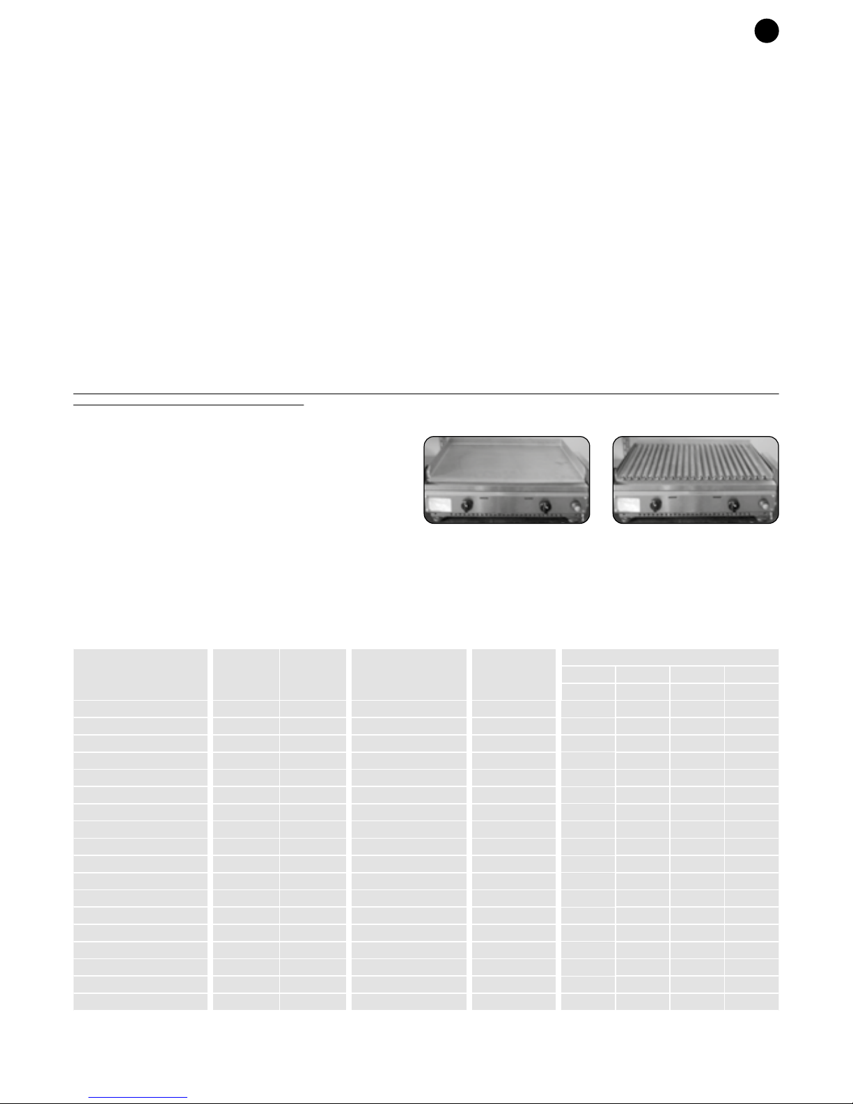
ES
• QUEMADOR: destornillar los tornillos que lo sujetan, quitarlo y volver a sujetar el nuevo.
• LLAMA DE ENCENDIDO: Destornillar el tornillo de fijación de la bujía y sacar el cable.
• GRIFO/LLAVE: quitar el porta goma de la parte trasera, destornillar el soporte / rampa, sacar la rampa unos 2 cm, destornillar el grifo y sustituirlo con uno nuevo
atornillándolo, asegurándose de que esté sellado (usar líquido bloca roscas o teflón homologado para gases).
EL CONSTRUCTOR RECHAZA TODA RESPONSABILIDAD DERIVADA DE UN USO INCORRECTO O DE UNA INSTALACIÓN ERRÓNEA DEL APARATO. PARA SU
SEGURIDAD
PER LA VOSTRA SICUREZZA
• Preste atención al modelo citado en la tarjeta de características técnicas, especialmente en lo que se refiere a:
• Los modelos PLA-GL … están predispuestos para ser alimentados únicamente con gas BUTANO o a PROPANO.
• Los modelos PLA-GM... están predispuestos para ser alimentados únicamente con gas METANO.
• Los aparatos se entregan con la preparación indicada en la placa. Una vez realizada la conexión del gas correspondiente, no se necesita ninguna intervención
de regulación en el aparato.
• Debe ubicar el aparato y la bombona sobre una superficie lisa y resguardados del viento, prestando atención a que no haya materiales inflamables cerca del aparato.
• Proteja la bombona de la radiación solar.
• No debe conservar las bombonas en casa, en lugares sin ventilación o en locales por debajo del nivel del suelo.
• CUIDADO: no cambie de lugar el aparato, incluso si tiene ruedas, durante su funcionamiento o si aún está caliente.
• Debe sustituir los tubos de conexión de gas dañados o si presentan poros, así como en aquellos casos en que se ha superado la fecha de caducidad impresa sobre ellos.
• No debe tirar ni pellizcar los tubos flexibles, así como no debe ponerlos en contacto con superficies calientes.
• Sólo aquellas personas autorizadas y cualificadas pueden llevar a cabo trabajos de mantenimiento y reparación.
• Cualquier modificación o alteración puede resultar peligrosa.
• Las planchas y rejillas alcanzan elevadas temperaturas durante la fase de cocción, tenga cuidado.
• No limpie ni moje con agua planchas o rejillas mientras éstas estén calientes, porque podría provocar la deformación de la superficie de cocción.
• Se recomienda que mantenga la bombona alejada del aparato durante el uso.
ESTE APARATO ES DE USO EXCLUSIVO EN EXTERIORES.
El aire necesario para la combustión es de 2,0 m 3 / h por cada KW de carga calorífica instalado (1 KW = 3412 BTU).
CUIDADO: LAS PARTES ACCESIBLES DEL APARATO DURANTE SU FUNCIONAMIENTO ALCANZAN TEMPERATURAS MUY ALTAS, POR LO QUE SE
RECOMIENDA MANTENER ALEJADOS A LOS NIÑOS
SI DETECTA OLOR A GAS:
1) Cierre la alimentación de gas del aparato;
2) Apague cualquier llama que se encuentre encendida;
3) Si el olor persiste, póngase en contacto con su suministrador de gas.
CARACTERÍSTICAS DE FABRICACIÓN
- El aparato está construido en acero inoxidable.
- Los quemadores son de tipo atmosférico.
- El aparato se suministra completo y acabado por el constructor. No necesita de
ninguna clase de montaje durante su instalación.
- Las versiones del aparato son las siguientes:
Versión con plancha Fry-Top Versión con rejilla de piedra lávica
PLA-GL40
PLA-GM40
PLA-GL40T
PLA-GM40T
PLA-GL55
PLA-GM55
PLA-GL55PL
PLA-GM55PL
PLA-GL60
PLA-GM60
PLA-GL70T
PLA-GM70T
PLA-GL80
PLA-GM80
PLA-GL80PL
PLA-GM80PL
PLA-GL26/55
PLA-GM26/55
Modelo
2,8
2,8
2,8
2,8
5,6
5,6
5,6
5,6
5,6
5,6
5,6
5,6
8,4
8,4
8,4
8,4
8,4
8,4
0,267
0,267
0,534
0,534
0,534
0,534
0,800
0,800
0,800
0,310
0,310
0,620
0,620
0,620
0,620
0,931
0,931
0,931
204
204
408
408
408
408
611
611
611
200
200
400
400
400
400
600
600
600
G20
m3/h
Consumo gas
G25
m3/h
G30
g/h
G31
g/h
370 x 435 x 180
370 x 435 x 180
370 x 532 x 180
520 x 370 x 180
530 x 435 x 180
530 x 435 x 180
536 x 432 x 180
536 x 432 x 180
600 x 435 x 180
600 x 435 x 180
680 x 532 x 180
680 x 532 x 180
790 x 435 x 180
790 x 435 x 180
791 x 432 x 180
791 x 432 x 180
806 x 432 x 180
806 x 432 x 180
N°
Quemadores
2,8 kW
Medidas
L x P x H mm
Potencia
(kW)
1
1
1
1
2
2
2
2
2
2
2
2
3
3
3
3
3
3
80
130
80
130
80
130
80
130
80
130
80
130
80
130
80
130
80
130
Ø tobera
1/100 mm
Page 16

NL
DE INSTALLATIE VAN HET APPARAAT
Het apparaat kan op een willekeurige ondergrond worden geplaatst, die voldoet aan de volgende voorschriften:
- Als de barbecue niet op de wagen PLANET wordt gepositioneerd, moet gecontroleerd worden dat het steunvlak bestendig is tegen een hitte van 120°C.
-Laat rondom het toestel een vrije ruimte van minstens 10 cm tot zijwanden en van minstens 15 cm tot de achterwand, waar een zeer hoge temperatuur wordt gevormd.
• STEL HET APPARAAT NIET IN WERKING IN DICHTE RUIMTES EN IN DE BUURT VAN BRANDBARE MATERIALEN.
• VERWIJDER HET (WITTE) BESCHERMENDE KLEEFFOLIE VOLLEDIG VAN HET STAAL.
AANSLUITING VAN HET TOESTEL, voorzien voor de:
A) WERKING MET BUTAAN / PROPAAN. (ZIE TABEL TECHNISCHE GEGEVENS)
Het apparaat moet worden aangesloten via:
• Een campinggasfles voor gezamenlijk gebruik met L.P.G. (vloeibaar gas).
• Een drukregelaar met vaste ijking, zoals voorgeschreven door de geldende nationale voorschriften, met
werkdruk, zoals op het plaatje wordt weergegeven.
• Flexibele slangen overeenkomstig de nationale voorschriften, met een geschikte lengte (max. 1,5 m),
waardoor een montage zonder vouwen en zonder verdraaiingen van de aansluitslang op het apparaat
te veroorzaken, mogelijk is.
• Lekdetectiespray of een sopje om de gasdichtheid te controleren.
AANSLUITING VAN HET APPARAAT OP DE GASFLES
1) Controleer dat het rubbertje van de gaskraan niet beschadigd is.
2) Sluit de drukregelaar aan op de gasfles (2).
3) Controleer dat de kranen van het apparaat dicht zijn.
4) Verbind de leiding op de regelaar (4), indien dit nog niet gebeurde, op basis van de van kracht zijnde
norm, en verbind daarna de buis op de reeds voorziene koppeling van het toestel (3). Monteer de
pakking correct tussen de verbinding en de slang, en breng de klemring (5) aan.
5) Plaats de gasfles op een vlakke en stabiele ondergrond. De fles kan op het ondervlak van het wagentje
PLA.NET geplaatst worden als ze een maximum inhoud va 5 kg gas heeft.
6) De gasfles dient buiten en ver uit de buurt van brandbaar materiaal te worden vervangen; de
vervangen gasfles dient met de speciale dopmoer te worden afgesloten en op een geschikte plaats te
worden bewaard.
B) WERKING MET METHAAN (ZIE TABEL TECHNISCHE GEGEVENS)
De aansluiting van het toestel op het gasnet moet uitgevoerd worden met een flexibele leiding volgens de
van kracht zijnde norm, en moet bevestigd worden op de reeds voorziene koppeling van het toestel (3).
monteer de pakking (5) correct tussen de ingang van de baan en de slang.
CONTROLE VAN DE DICHTHEID
Controleer de dichtheid van de aansluiting bij werkdruk met een lekopsporingspray of met zeepwater. De dichtheid is correct als geen luchtbellen gevormd worden.
Controleer gaslekken nooit met een vlam!
GEBRUIKSAANWIJZING
• Controleer dat het apparaat correct geplaatst is.
• Controleer dat alle onderdelen juist aangebracht zijn.
• Controleer dat de aansluiting conform verricht is.
• Controleer dat de gasfles zich op minstens 50 cm van het apparaat bevindt.
• Controleer of de gasleiding het toestel niet raakt en zich niet nabij de uitvoer van warme lucht achteraan het toestel bevindt.
POWER
• Open het gas van de gasfles of van het gasnet (bij werking op methaan) door het kraantje naar links te draaien.
PIËZO-ELEKTRISCHE / ELEKTRONISCHE ONTSTEKING
• Druk op de knop en draai hem tegelijkertijd helemaal tegen de klok in op de hoogste stand en houd de knop ingedrukt.
• Maak het gas aan door op de knop van de piëzo-elektrische ontsteking te drukken; houd de knop nog enkele seconden ingedrukt, nadat de brander is gaan branden.
• Als de brander eenmaal brandt, kan de vlam ook op klein gezet worden.
ELEKTRONISCHE ONTSTEKING MET VENTIEL (model GL/GMxxT)
• Druk de knop in en draai deze tegelijkertijd linksom naar de maximum stand, en houd de knop ingedrukt om de elektronische ontsteking te starten.
N.B: voor de eerste ontsteking moet de knop 10/15 sec. lang ingedrukt gehouden worden, tot de vlam verschijnt.
• Nadat de ontsteking is uitgevoerd, moet de knop enkele seconden ingedrukt gehouden worden zodat het thermokoppel wordt geactiveerd.
• De ingeschakelde brander kan gezien worden via de openingen; indien deze niet zou branden, kan de handeling na 1 minuut herhaald worden.
• Nadat de ontsteking is uitgevoerd, moet de vlam op de minimum stand geregeld worden.
UITSCHAKELING
• Draai na de bereiding de draaiknop in POSITIE UIT, en sluit de kraan van de gasfles of van het gasnet.
• U kunt de brandende brander door de opening in het bedieningspaneel zien.
BEREINDING
• De eerste keren dat het apparaat gebruikt wordt, dient gematigd vuur te worden gebruikt, zodat de platen/roosters zich kunnen "stabiliseren".
• Maak geen diepgevrozen voedsel klaar, er zal geen optimale bereiding worden verkregen en het materiaal van het bereidingsvlak zou vervormd kunnen worden als gevolg
van een thermische shock.
• Hou het bakje dat het vet/vuil opvangt onder controle. Maak het indien noodzakelijk leeg, maar bescherm uw handen met thermische handschoenen (het bakje zou zeer
heet kunnen zijn).
• Laat het toestel niet ingeschakeld wanneer geen te bereiden voedsel aanwezig is, zodat het kookvlak niet te heet wordt.
Dit kan gevaarlijk zijn voor de personen en zou het vlak zelf kunnen vervormen.
DE VLAM REGELEN
De vlam kan geregeld worden.
Op de draaiknop / het bedieningspaneel zijn de volgende symbolen aanwezig:
REINIGING
- Voor meer informatie wordt verwezen naar de handleiding voor het gebruik en het onderhoud en de garantie
- Neem bij technische problemen contact op met de technische servicedienst.
VERVANGING RESERVEONDERDELEN
DEZE HANDELING MAG ALLEEN WORDEN VERRICHT DOOR EEN GESPECIALISEERDE TECHNICUS VAN DE FABRIKANT.
De onderdelen die vervangen kunnen worden zijn eenvoudig toegankelijk. Het is voldoende om de draaiknoppen te verwijderen en de plaat op te heffen zodat het paneel kan
verwijderd worden door de schroeven los te draaien.
2
4
3
5
UIT
MAXIMUM VERMOGEN
MINIMUM VERMOGEN
NL
• BRANDER: draai de bevestigingsschroef los, verwijder ze en plaats de nieuwe.
• ONTSTEKINGSBOUGIE: draai de bevestigingsschroef van de bougie los, en verwijder de kabel
• KRAAN: verwijder de klem achteraan, draai de steun/gasstraat los, verwijder de gasstraat ongeveer 2 cm, draai de kraan los en vervang ze met een nieuwe.
Controleer of de kraan niet lekt (gebruik een schroefdraaddichting of teflon dat gehomologeerd is voor gas)
DE FABRIKANT WIJST ELKE VORM VAN AANSPRAKELIJKHEID AF BIJ EEN VERKEERD GEBRUIK OF VERKEERDE INSTALLATIE VAN HET APPARAAT.
VOOR UW VEILIGHEID
• Let op het model dat op het plaatje staat, omdat:
• De modellen PLA-GL … ervoor bestemd zijn uitsluitend met BUTAAN of PROPAAN.
• De modellen PLA-GM … ervoor bestemd zijn uitsluitend met METHAAN.
• De apparaten worden compleet afgeleverd zoals aangegeven op het plaatje. Zodra het eenmaal aangesloten is op het juiste soort gas hoeft het apparaat niet
verder te worden afgesteld.
• Het apparaat en de gasfles dienen windvrij op een vlakke bodem te worden geplaatst. Let erop dat zich in de onmiddellijke nabijheid van het apparaat geen brandbare
materialen bevinden.
• Bescherm de gasfles tegen de zon.
• De gasflessen mogen niet in huis, niet op ongeventileerde plaatsen en niet in ruimtes onder de grond bewaard worden.
• LET OP: verplaats het apparaat niet tijdens de werking of als het nog warm is, ook al heeft het wielen.
• De slangen dienen te worden vervangen als ze kapot of poreus zijn en als de vervaldatum die erop staat verstreken is.
• De flexibele slangen mogen niet gespannen zijn, niet afgekneld worden, of in aanraking komen met warme oppervlakken.
• Onderhouds- en reparatiewerkzaamheden mogen alleen door erkend en bekwaam personeel worden verricht.
• Alle wijzigingen of forceringen kunnen gevaarlijk zijn.
• Tijdens de bereidingsfase bereiken de platen/roosters hoge temperaturen. Kijk dus goed uit.
• Was de plaat/het rooster niet af en maak het niet nat met water als deze warm is. omdat zo de kookplaat zou kunnen vervormd worden.
• Aanbevolen wordt de gasfles tijdens het gebruik uit de buurt van het apparaat te houden.
DIT APPARAAT IS UITSLUITEND BESTEMD OM BUITEN TE WORDEN GEBRUIKT.
De lucht die nodig is voor de verbranding is 2,0 m 3 / h voor iedere KW geïnstalleerde warmte-afgifte (1 KW = 3412 BTU).
LET OP: DE TOEGANKELIJKE DELEN VAN HET APPARAAT WORDEN TIJDENS HET GEBRUIK ERG HEET. DAAROM WORDT AANBEVOLEN KINDEREN UIT DE
BUURT ERVAN TE HOUDEN
ALS U EEN GASLUCHT RUIKT:
1) Sluit de gastoevoer naar het apparaat;
2) Doe alle open vlammen uit;
3) Wend u tot uw gasleverancier als de gaslucht blijft aanhouden.
CONSTRUCTIEKENMERKEN
- Het toestel is gemaakt van roestvrij staal.
- De branders zijn van het atmosferische type.
- Het apparaat wordt compleet en door de fabrikant afgewerkt geleverd;bij de
installatie zijn geen bijzondere montages nodig.
- Het apparaat is verkrijgbaar in de volgende uitvoeringen:
Uitvoering met Fry-Top plaat Uitvoering met lavasteenrooster
PLA-GL40
PLA-GM40
PLA-GL40T
PLA-GM40T
PLA-GL55
PLA-GM55
PLA-GL55PL
PLA-GM55PL
PLA-GL60
PLA-GM60
PLA-GL70T
PLA-GM70T
PLA-GL80
PLA-GM80
PLA-GL80PL
PLA-GM80PL
PLA-GL26/55
PLA-GM26/55
Model
2,8
2,8
2,8
2,8
5,6
5,6
5,6
5,6
5,6
5,6
5,6
5,6
8,4
8,4
8,4
8,4
8,4
8,4
0,267
0,267
0,534
0,534
0,534
0,534
0,800
0,800
0,800
0,310
0,310
0,620
0,620
0,620
0,620
0,931
0,931
0,931
204
204
408
408
408
408
611
611
611
200
200
400
400
400
400
600
600
600
G20
m3/h
Verbruik gas
G25
m3/h
G30
g/h
G31
g/h
370 x 435 x 180
370 x 435 x 180
370 x 532 x 180
520 x 370 x 180
530 x 435 x 180
530 x 435 x 180
536 x 432 x 180
536 x 432 x 180
600 x 435 x 180
600 x 435 x 180
680 x 532 x 180
680 x 532 x 180
790 x 435 x 180
790 x 435 x 180
791 x 432 x 180
791 x 432 x 180
806 x 432 x 180
806 x 432 x 180
N°
Aantal branders
2,8 kW
Afmetingen
L x P x H mm
Vermogebn
(kW)
1
1
1
1
2
2
2
2
2
2
2
2
3
3
3
3
3
3
80
130
80
130
80
130
80
130
80
130
80
130
80
130
80
130
80
130
Ø spuitmond
1/100 mm
Page 17

NL
• BRANDER: draai de bevestigingsschroef los, verwijder ze en plaats de nieuwe.
• ONTSTEKINGSBOUGIE: draai de bevestigingsschroef van de bougie los, en verwijder de kabel
• KRAAN: verwijder de klem achteraan, draai de steun/gasstraat los, verwijder de gasstraat ongeveer 2 cm, draai de kraan los en vervang ze met een nieuwe.
Controleer of de kraan niet lekt (gebruik een schroefdraaddichting of teflon dat gehomologeerd is voor gas)
DE FABRIKANT WIJST ELKE VORM VAN AANSPRAKELIJKHEID AF BIJ EEN VERKEERD GEBRUIK OF VERKEERDE INSTALLATIE VAN HET APPARAAT.
VOOR UW VEILIGHEID
• Let op het model dat op het plaatje staat, omdat:
• De modellen PLA-GL … ervoor bestemd zijn uitsluitend met BUTAAN of PROPAAN.
• De modellen PLA-GM … ervoor bestemd zijn uitsluitend met METHAAN.
• De apparaten worden compleet afgeleverd zoals aangegeven op het plaatje. Zodra het eenmaal aangesloten is op het juiste soort gas hoeft het apparaat niet
verder te worden afgesteld.
• Het apparaat en de gasfles dienen windvrij op een vlakke bodem te worden geplaatst. Let erop dat zich in de onmiddellijke nabijheid van het apparaat geen brandbare
materialen bevinden.
• Bescherm de gasfles tegen de zon.
• De gasflessen mogen niet in huis, niet op ongeventileerde plaatsen en niet in ruimtes onder de grond bewaard worden.
• LET OP: verplaats het apparaat niet tijdens de werking of als het nog warm is, ook al heeft het wielen.
• De slangen dienen te worden vervangen als ze kapot of poreus zijn en als de vervaldatum die erop staat verstreken is.
• De flexibele slangen mogen niet gespannen zijn, niet afgekneld worden, of in aanraking komen met warme oppervlakken.
• Onderhouds- en reparatiewerkzaamheden mogen alleen door erkend en bekwaam personeel worden verricht.
• Alle wijzigingen of forceringen kunnen gevaarlijk zijn.
• Tijdens de bereidingsfase bereiken de platen/roosters hoge temperaturen. Kijk dus goed uit.
• Was de plaat/het rooster niet af en maak het niet nat met water als deze warm is. omdat zo de kookplaat zou kunnen vervormd worden.
• Aanbevolen wordt de gasfles tijdens het gebruik uit de buurt van het apparaat te houden.
DIT APPARAAT IS UITSLUITEND BESTEMD OM BUITEN TE WORDEN GEBRUIKT.
De lucht die nodig is voor de verbranding is 2,0 m 3 / h voor iedere KW geïnstalleerde warmte-afgifte (1 KW = 3412 BTU).
LET OP: DE TOEGANKELIJKE DELEN VAN HET APPARAAT WORDEN TIJDENS HET GEBRUIK ERG HEET. DAAROM WORDT AANBEVOLEN KINDEREN UIT DE
BUURT ERVAN TE HOUDEN
ALS U EEN GASLUCHT RUIKT:
1) Sluit de gastoevoer naar het apparaat;
2) Doe alle open vlammen uit;
3) Wend u tot uw gasleverancier als de gaslucht blijft aanhouden.
CONSTRUCTIEKENMERKEN
- Het toestel is gemaakt van roestvrij staal.
- De branders zijn van het atmosferische type.
- Het apparaat wordt compleet en door de fabrikant afgewerkt geleverd;bij de
installatie zijn geen bijzondere montages nodig.
- Het apparaat is verkrijgbaar in de volgende uitvoeringen:
Uitvoering met Fry-Top plaat Uitvoering met lavasteenrooster
PLA-GL40
PLA-GM40
PLA-GL40T
PLA-GM40T
PLA-GL55
PLA-GM55
PLA-GL55PL
PLA-GM55PL
PLA-GL60
PLA-GM60
PLA-GL70T
PLA-GM70T
PLA-GL80
PLA-GM80
PLA-GL80PL
PLA-GM80PL
PLA-GL26/55
PLA-GM26/55
Model
2,8
2,8
2,8
2,8
5,6
5,6
5,6
5,6
5,6
5,6
5,6
5,6
8,4
8,4
8,4
8,4
8,4
8,4
0,267
0,267
0,534
0,534
0,534
0,534
0,800
0,800
0,800
0,310
0,310
0,620
0,620
0,620
0,620
0,931
0,931
0,931
204
204
408
408
408
408
611
611
611
200
200
400
400
400
400
600
600
600
G20
m3/h
Verbruik gas
G25
m3/h
G30
g/h
G31
g/h
370 x 435 x 180
370 x 435 x 180
370 x 532 x 180
520 x 370 x 180
530 x 435 x 180
530 x 435 x 180
536 x 432 x 180
536 x 432 x 180
600 x 435 x 180
600 x 435 x 180
680 x 532 x 180
680 x 532 x 180
790 x 435 x 180
790 x 435 x 180
791 x 432 x 180
791 x 432 x 180
806 x 432 x 180
806 x 432 x 180
N°
Aantal branders
2,8 kW
Afmetingen
L x P x H mm
Vermogebn
(kW)
1
1
1
1
2
2
2
2
2
2
2
2
3
3
3
3
3
3
80
130
80
130
80
130
80
130
80
130
80
130
80
130
80
130
80
130
Ø spuitmond
1/100 mm
Page 18
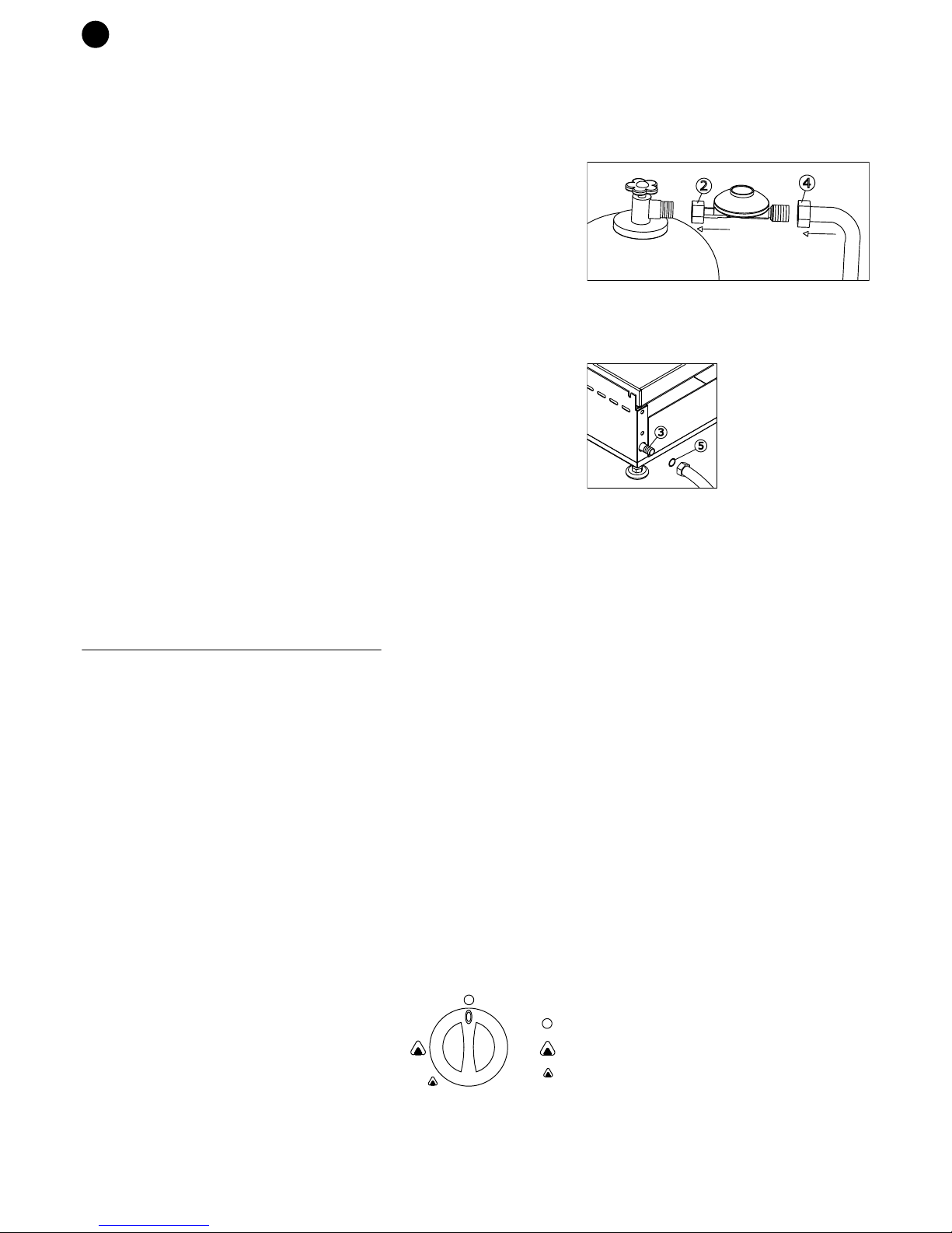
NO
INSTALLASJON AV APPARATET
Apparatet kan plasseres på en hvilken som helst flate, man må kun ta hensyn til følgende krav:
- Hvis utegrillen ikke skal settes på PLANET-vognen, må du forsikre deg om at flaten eller bordet du setter den på tåler opp til 120 °C.
- Pass på at det omkring apparatet er minst 10 cm luftrom på sidene og 15 cm bak apparatet hvor det befinner seg et varmluftutløp med svært høy temperatur.
• BRUK ALDRI APPARATET I LUKKEDE ROM, ELLER I NÆRHETEN AV BRENNBART MATERIALE.
• DEN BESKYTTENDE KLEBEFILMEN (HVIT) MÅ ABSOLUTT FJERNES FRA STÅLET.
TILKOPLING AV APPARATET egnet for:
A) DRIFT MED BUTANGASS/PROPANGASS (SE TABELL MED TEKNISKE DATA)
Tilkoplingen av apparatet må utføres ved hjelp av:
• Vanlig gassflaske for campingbruk med propangass- innhold (flytende gass).
• Trykkregulator med fast tarering som avhenger av normer i det land den selges i, med funksjonstrykk
som angitt på merkeskiltet.
• Slanger i samsvar med det gjeldende lovverket, med tilstrekkelig lengde (maks. 1,5 m), som muliggjør
montering uten å bøye slangen, og uten folder på tilkoplingsslanget til apparatet.
• Spray for oppdaging av lekkasje, evt. såpevann for å kontrollere at slangen er tett.
TILKOPLING AV APPARATET TIL GASSFLASKEN
1) Kontroller at pakningen på å gasskranen på flasken er i uten feil.
2) Koble trykkregulatoren til gassbeholderen (2).
3) Kontroller at gasskranene på apparatet er i avstengt posisjon.
4) Koble røret til regulatoren (4), dersom den ikke allerede er festet, det vil si røret festes til
koblingskontakten som befinner seg på apparatet (3) i overensstemmelse med de gjeldende forskrifter.
mount pakningen korrekt mellom koblingsstykket og slangekoblingen og skru slangeklemmen fast på
slangen (5)
5) Plasser gassbeholderen på et flatt underlag og kontroller at underlaget er stabilt. Den kan plasseres på
underplaten til PLA.NET vognen dersom gassbeholderen ikke veier mer enn 5 kg.
6) Når man skifter gassflaske, må dette skje på god avstand fra brennbart materiale og utendørs. Den
flasken som byttes ut è må stenges med den medfølgende mutteren, og så oppbevares på egnet sted.
B) DRIFT MED METANGASS (SE TABELL MED TEKNISKE DATA)
Tilkoblingen av apparatet til distribusjonsnettet må utføres med et fleksibelt rør i overens-stemmelse med
de gjeldende forskriftene, og må festes til koblingskontakten som befinner seg på apparatet (3). mount
pakningen (5) mellom gassrøret på baksiden av grillen og slangekoblingen.
KONTROLL AV FESTE/ TETTHET
Kontroll av at tilkoplingen er tett gjøres ved hjelp av en spray for oppdaging av lekkasje, evt. såpevann for å kontrollere at slangen er tett. Tilkoplingen er tett når det ikke
oppstår bobler.
Man må aldri kontrollere for gasslekkasjer med fyrstikk eller flamme!
BRUKSANVISNING
• Kontroller at apparatet er riktig plassert.
• Kontroller at alle komponenter er blitt riktig satt på.
• Kontroller at tilkoplingen er i samsvar med beskrivelsen og gjeldende normer.
• Kontroller at gassrøret ikke er i kontakt med apparatet eller er i nærheten av varmluftsutløpet på baksiden av apparatet.
• Kontroller at gassflasken befinner seg minst 50 cm fra apparatet.
TENNING
• Åpne gasstilførselen fra gassflasken eller fra gassledningen (for bruk med metangass) ved å vri kranen måt venstre.
PIEZO-/ ELEKTRONISK TENNING
• Trykk og vri samtidig mot bryteren mot venstre til maksimumsinnstillingen og hold inne bryteren.
• Slå på gassen ved å trykke på gnistbryteren; etter at brenneren er blitt tent fortsetter man å holde inne bryteren i noen sekunder.
• Når brenneren er tent kan man justere flammen slik man ønsker, også til minimum.
ELEKTRONISK TENNING MED TENNSIKRING (mod. GL/GMxxT)
• Trykk innstillingsbryteren inn og vri den mot klokken til maksimumspunktet. Hold bryteren inne for å tenne den elektroniske tenningen.
NB: Når grillen tennes første gang må bryteren holdes inne i 10-15 sek. til flammen tennes.
• Når blusset er tent, holder du bryteren inne i noen sekunder slik at termoelementet starter.
• Du vil kunne se at blusset er tent gjennom hullene på betjeningspanelet. Hvis blusset ikke er tent, kan du prøve igjen etter 1 minutt.
• Når blusset er tent justeres flammen til minimumspunktet.
SLUKKING
• Etter avsluttet steking drei håndtaket i LUKKET POSISJON og lukk kranen til gassbeholderen eller til distribusjonsnettet
• Gjennom åpningen i dekslet kan man kontrollere om brenneren er blitt tent.
STEKING
• De første gangene man tenner grillen må man bruke middels flamme, slik at platene/ grillene får tid til å "stabilisere seg".
• Stek ikke nedfryste matvarer. Det oppnår man ikke noe godt resultat av og det kan føre til skader på materialet til stekeplaten grunnet termisk sjokk.
• Hold et øye med oppsamlingskaret av olje/skitt og tøm det når nødvendig. Pass på å beskytte hendene (karet kan være svært varmt).
• La ikke apparatet være slått på når matlaging ikke pågår, for slik å unngå at platen ikke når svært høye temperaturer.
Dette kan være farlig for personer i nærheten og føre til skader på materialet.
JUSTERING AV FLAMMEN
Flammen kan justeres.
På håndtaket /instrumentpanelet står det skrevet følgende symboler:
RENGJØRING - VEDLIKEHOLD
- For ytterligere informasjon, se bruks- og vedlikeholdsveiledningen og garantiheftet.
- For alle problemer av teknisk art, må man kontakte teknisk assistanse
BYTTING AV DELER
DENNE OPERASJONEN MÅ KUN UTFØRES AV EN TEKNISK FAGMANN GODKJENT AV PRODUSENTEN.
De delene som kan skiftes ut er lett tilgjengelige. Det er nok å ta bort håndtakene, løfte platen og fjerne instrumentpanelet ved å skru av festeskruene.
2
4
3
5
STENGT
MAKSIMUM STYRKE
MINIMUM STYRKE
NO
• BRENNER: skru av festeskruene, ta den bort og feste den til på nytt.
• TENNPLUGG: Skru opp tennpluggens festeskrue og trekk ut ledningen
• KRANEN: fjern slangekoblingen på baksiden, skru av støtteplaten/rampen, trekk ut rampen ca 2 cm, skru av kranen og skift den ut med å skru på en ny. Vær forsikret om at
den er tett (bruk montasjelim eller teflon godkjent for gass)
PRODUSENTEN FRASIR SEG ETHVERT ANSVAR FOR KONSEKVENSER AV FEIL BRUK ELLER FEIL INSTALLASJON AV APPARATET.
FOR DIN EGEN SIKKERHET
• Vær oppmerksom må modellnummeret du finner på merkeskiltet, fordi:
• Modellene PLA-GL … kun er beregnet til bruk sammen med BUTANgass eller PROPANgass .
• Modellene PLA-GM … er kun beregnet til bruk med tilførsel av METANgass
• Apparatene leveres forhåndsinnstilt som angitt på typeskiltet. Når tilkoblingen til tilsvarende gasstype er utført, er det ikke nødvendig å foreta noen regulering
på apparatet.
• Apparatet og gassflasken må settes på et jevnt gulv eller flate, i ly for vinden, og man må passe på at det ikke finnes brennbare materialer i nærheten.
• Beskytt gassflasken mot direkte sollys.
• Gassflasker kan ikke oppbevares inne i huset, på steder uten god lufting, eller under bakkenivå.
• VÆR OPPMERKSOM: Unngå å flyte på apparatet når det er i bruk eller fremdeles varmt, selv om det er utstyrt med hjul.
• Ødelagte eller porøse tilkoplingsslanger for gass må byttes, det samme må gjøres når utløpsdatoen på slangen (stemplet på) er passert.
• Man må ikke trekke i, knipe sammen eller berøre gummislangene med varme objekter/ overflater.
• Vedlikeholdsarbeid og reparasjoner må kun utføres av autoriserte fagfolk.
• Alle endringer og inngrep på apparatet kan føre til farlige situasjoner.
• Stekeplatene/ grillene vil ved grilling nå høye temperaturer, vær oppmerksom.
• Ikke vask eller hell vann på platen/grillene når den er varm. Det kan føre til at platen deformeres
• Det anbefales at gassflasken holde spå god avstand fra apparatet under bruk.
DETTE APPARATET ER KUN BEREGNET IL UTENDØRS BRUK.
Luften som er nødvendig for forbrenning er 2,0 m 3 / h for hver KW termisk potensial som er installert (1 KW = 3412 BTU).
VÆR OPPMERKSOM: DELER AV APPARATET SOM LETT KAN BERØRES BLIR UNDER BRUK SVÆRT VARME. DERFOR ANBEFALES DET Å HOLDE BARN PÅ
GOD AVSTAND.
DERSOM MAN KJENNER LUKT AV GASS
1) Lukk tilførselen av gass til apparatet.
2) Slukk alle former for åpen flamme.
3) Dersom lukten vedvarer må man kontakte gassleverandøren.
KONSTRUKSJONSEGENSKAPER
- Apparatet er laget av rustfritt stål.
- Brennerne er av atmosfærisk type.
- Apparatet leveres komplett og ferdig fra produsenten,det har ikke behov for
særskilt montering før installasjon.
- Apparatet finnes i følgende versjoner:
Versjon med stekeplate Fry-Top Versjon med lavasteinsgrill
PLA-GL40
PLA-GM40
PLA-GL40T
PLA-GM40T
PLA-GL55
PLA-GM55
PLA-GL55PL
PLA-GM55PL
PLA-GL60
PLA-GM60
PLA-GL70T
PLA-GM70T
PLA-GL80
PLA-GM80
PLA-GL80PL
PLA-GM80PL
PLA-GL26/55
PLA-GM26/55
Modell
2,8
2,8
2,8
2,8
5,6
5,6
5,6
5,6
5,6
5,6
5,6
5,6
8,4
8,4
8,4
8,4
8,4
8,4
0,267
0,267
0,534
0,534
0,534
0,534
0,800
0,800
0,800
0,310
0,310
0,620
0,620
0,620
0,620
0,931
0,931
0,931
204
204
408
408
408
408
611
611
611
200
200
400
400
400
400
600
600
600
G20
m3/h
Forbruk gas
G25
m3/h
G30
g/h
G31
g/h
370 x 435 x 180
370 x 435 x 180
370 x 532 x 180
520 x 370 x 180
530 x 435 x 180
530 x 435 x 180
536 x 432 x 180
536 x 432 x 180
600 x 435 x 180
600 x 435 x 180
680 x 532 x 180
680 x 532 x 180
790 x 435 x 180
790 x 435 x 180
791 x 432 x 180
791 x 432 x 180
806 x 432 x 180
806 x 432 x 180
N°
Brennere
2,8 kW
Dimensjoner
L x D x H mm
Kraft
(kW)
1
1
1
1
2
2
2
2
2
2
2
2
3
3
3
3
3
3
80
130
80
130
80
130
80
130
80
130
80
130
80
130
80
130
80
130
Ø dyse
1/100 mm
Page 19

NO
• BRENNER: skru av festeskruene, ta den bort og feste den til på nytt.
• TENNPLUGG: Skru opp tennpluggens festeskrue og trekk ut ledningen
• KRANEN: fjern slangekoblingen på baksiden, skru av støtteplaten/rampen, trekk ut rampen ca 2 cm, skru av kranen og skift den ut med å skru på en ny. Vær forsikret om at
den er tett (bruk montasjelim eller teflon godkjent for gass)
PRODUSENTEN FRASIR SEG ETHVERT ANSVAR FOR KONSEKVENSER AV FEIL BRUK ELLER FEIL INSTALLASJON AV APPARATET.
FOR DIN EGEN SIKKERHET
• Vær oppmerksom må modellnummeret du finner på merkeskiltet, fordi:
• Modellene PLA-GL … kun er beregnet til bruk sammen med BUTANgass eller PROPANgass .
• Modellene PLA-GM … er kun beregnet til bruk med tilførsel av METANgass
• Apparatene leveres forhåndsinnstilt som angitt på typeskiltet. Når tilkoblingen til tilsvarende gasstype er utført, er det ikke nødvendig å foreta noen regulering
på apparatet.
• Apparatet og gassflasken må settes på et jevnt gulv eller flate, i ly for vinden, og man må passe på at det ikke finnes brennbare materialer i nærheten.
• Beskytt gassflasken mot direkte sollys.
• Gassflasker kan ikke oppbevares inne i huset, på steder uten god lufting, eller under bakkenivå.
• VÆR OPPMERKSOM: Unngå å flyte på apparatet når det er i bruk eller fremdeles varmt, selv om det er utstyrt med hjul.
• Ødelagte eller porøse tilkoplingsslanger for gass må byttes, det samme må gjøres når utløpsdatoen på slangen (stemplet på) er passert.
• Man må ikke trekke i, knipe sammen eller berøre gummislangene med varme objekter/ overflater.
• Vedlikeholdsarbeid og reparasjoner må kun utføres av autoriserte fagfolk.
• Alle endringer og inngrep på apparatet kan føre til farlige situasjoner.
• Stekeplatene/ grillene vil ved grilling nå høye temperaturer, vær oppmerksom.
• Ikke vask eller hell vann på platen/grillene når den er varm. Det kan føre til at platen deformeres
• Det anbefales at gassflasken holde spå god avstand fra apparatet under bruk.
DETTE APPARATET ER KUN BEREGNET IL UTENDØRS BRUK.
Luften som er nødvendig for forbrenning er 2,0 m 3 / h for hver KW termisk potensial som er installert (1 KW = 3412 BTU).
VÆR OPPMERKSOM: DELER AV APPARATET SOM LETT KAN BERØRES BLIR UNDER BRUK SVÆRT VARME. DERFOR ANBEFALES DET Å HOLDE BARN PÅ
GOD AVSTAND.
DERSOM MAN KJENNER LUKT AV GASS
1) Lukk tilførselen av gass til apparatet.
2) Slukk alle former for åpen flamme.
3) Dersom lukten vedvarer må man kontakte gassleverandøren.
KONSTRUKSJONSEGENSKAPER
- Apparatet er laget av rustfritt stål.
- Brennerne er av atmosfærisk type.
- Apparatet leveres komplett og ferdig fra produsenten,det har ikke behov for
særskilt montering før installasjon.
- Apparatet finnes i følgende versjoner:
Versjon med stekeplate Fry-Top Versjon med lavasteinsgrill
PLA-GL40
PLA-GM40
PLA-GL40T
PLA-GM40T
PLA-GL55
PLA-GM55
PLA-GL55PL
PLA-GM55PL
PLA-GL60
PLA-GM60
PLA-GL70T
PLA-GM70T
PLA-GL80
PLA-GM80
PLA-GL80PL
PLA-GM80PL
PLA-GL26/55
PLA-GM26/55
Modell
2,8
2,8
2,8
2,8
5,6
5,6
5,6
5,6
5,6
5,6
5,6
5,6
8,4
8,4
8,4
8,4
8,4
8,4
0,267
0,267
0,534
0,534
0,534
0,534
0,800
0,800
0,800
0,310
0,310
0,620
0,620
0,620
0,620
0,931
0,931
0,931
204
204
408
408
408
408
611
611
611
200
200
400
400
400
400
600
600
600
G20
m3/h
Forbruk gas
G25
m3/h
G30
g/h
G31
g/h
370 x 435 x 180
370 x 435 x 180
370 x 532 x 180
520 x 370 x 180
530 x 435 x 180
530 x 435 x 180
536 x 432 x 180
536 x 432 x 180
600 x 435 x 180
600 x 435 x 180
680 x 532 x 180
680 x 532 x 180
790 x 435 x 180
790 x 435 x 180
791 x 432 x 180
791 x 432 x 180
806 x 432 x 180
806 x 432 x 180
N°
Brennere
2,8 kW
Dimensjoner
L x D x H mm
Kraft
(kW)
1
1
1
1
2
2
2
2
2
2
2
2
3
3
3
3
3
3
80
130
80
130
80
130
80
130
80
130
80
130
80
130
80
130
80
130
Ø dyse
1/100 mm
Page 20

LEVIGMATIC S.r.l. - Via dell'Industria, 71/39 - 31020 San Vendemiano (TV) - Italy - Tel. +39 (0)438 470552 - Fax +39 (0)438 478705
info@planet-food.it - www.planet-food.it - www.planet-barbecue.com
Cod. 8204013 Rev. 5
Targhetta tecnica - Type label
Plaquette signalétique - Typenschild
NO
FR
AT
AT
BE
DE
NL
I3B/P
I3+
I3B/P
I2H
I2E+
I2ELL
I
2L
HU
BE
CH
CZ
SE
GB
DE
DK
DK
IE
FI
FI
ES
GB
NL
CH
IE
G20
20pmbar
20 pmbar
G20/25
20/25 pmbar
G25
20 pmbar
25 pmbar
G30
30 pmbar
28/30 pmbar
50 pmbar
G31
30 pmbar
37 pmbar
50 pmbar
CZ
GR
IT
SK
PT
NO
SI
IT
PT SK SI ES SE CH
Paesi - Countries - pays - Länder - Países - Land - Länder
Maat - Lande - Landen - ƪNjljƹdžǔ
CAT/K AT
METANO/METAN
BUTANO/BUTAN
PROPANO/PROPAN
 Loading...