

Page 1
User’s Manual of MGSD-10080F
1
Page 2

User’s Manual of MGSD-10080F
2
Trademarks
Copyright © PLANET Technology Corp. 2013.
Contents are subject to revise without prior notice.
PLANET is a registered trademark of PLANET Technology Corp. All other trademarks belong to their respective owners.
Disclaimer
PLANET Technology does not warrant that the hardware will work properly in all environments and applications, and makes no
warranty and representation, either implied or expressed, with respect to the quality, performance, merchantability, or fitness for
a particular purpose. PLANET has made every effort to ensure that this User's Manual is accurate; PLANET disclaims liability
for any inaccuracies or omissions that may have occurred.
Information in this User's Manual is subject to change without notice and does not represent a commitment on the part of
PLANET. PLANET assumes no responsib ility for any inaccuracies that may be co nt a ined in t hi s User's Manual. PLANET makes
no commitment to updat e or k eep curr en t the information in this U ser 's Manual, and reserves th e ri ght to make improvement s t o
this User's Manual and/or to the products described in this User's Manual, at any time without notice.
If you find information in this manual that is incorrect, misleading, or incomplete, we would appreciate your comments and
suggestions.
FCC Warning
This equipment has been tested and found to comply with the limits for a Class A digital device, pursuant to Part 15 of the FCC
Rules. These limits are designed to provide reasonable protection against harmful interference when the equipment is operated
in a commercial environment. This equipment generates, uses, and can radiate radio frequency energy and, if not installed and
used in accordance with the Instruction manual, may cause harmful interference to radio communications. Operation of this
equipment in a residential area is likely to cause harmful interference in which case the user will be required to correct the
interference at his own expense.
CE Mark Warning
This is a Class A product. In a domestic environment, this product may cause radio interference, in which case the user may be
required to take adequate measures.
Energy Saving Note of the Device
This power required device does not support Standby mode operation. For energy saving, please remove the power cable to
disconnect the device from the power circuit. In view of saving the energy and reducing the unnecessary power consumption, it
is strongly suggested to remove the power connection for the device if this device is not intended to be active.
WEEE Warning
To avoid the potential effects on the environment and human health as a result of the presence of
hazardous substances in electrical and electronic equipment, end users of electrical and electronic
equipment should understand the meaning of the crossed-out wheeled bin symbol. Do not dispose of
WEEE as unsorted municipal w aste and have to colle ct such WEEE separately.
Revision
PLANET 8-Port 100/1000X SFP + 2-Port 10/100/1000T Managed Metro Ethernet Switch User's Manual
FOR MODEL: MGSD-10080F
REVISION: 1.1 (June, 2013)
Part No: EM-MGSD-10080F_v1.1 (2080-A35140-001)
Page 3

User’s Manual of MGSD-10080F
3
TABLE OF CONTENTS
1. INTRODUCTION .................................................................................................................. 24
1.1 Packet Contents ......................................................................................................................................... 24
1.2 Product Descriptions ................................................................................................................................. 25
1.3 How to Use This Manual ............................................................................................................................ 27
1.4 Product Features ........................................................................................................................................ 29
1.5 Product Specificatio n s .............................................................................................................................. 32
2. INSTALLATION ................................................................................................................... 35
2.1 Hardware Descriptions .............................................................................................................................. 35
2.1.1 Front Panel .......................................................................................................................................................... 35
2.1.2 LED Indications ................................................................................................................................................... 37
2.1.3 Wiring the AC Power Input................................................................................................................................... 38
2.1.4 Wiring the DC Power Input .................................................................................................................................. 39
2.1.5 Wiring the Faulty Alarm Contact .......................................................................................................................... 40
2.1.6 Wiring the Digital Input / Output ........................................................................................................................... 41
2.2 Install the Managed Switch ....................................................................................................................... 44
2.2.1 Desktop Installat i on ............................................................................................................................................. 44
2.2.2 Rack Mounting ..................................................................................................................................................... 45
2.3 Cabling ........................................................................................................................................................ 46
2.3.1 Installing the SFP Transceiver ............................................................................................................................. 47
2.3.2 Remove the Module ............................................................................................................................................ 49
3. SWITCH MANAGEMENT .................................................................................................... 50
3.1 Requirements .............................................................................................................................................. 50
3.2 Management Access Overview ................................................................................................................. 51
3.3 CLI Mode Management .............................................................................................................................. 52
3.4 Web Management ....................................................................................................................................... 54
3.5 SNMP-Based Network Management ......................................................................................................... 55
3.6 PLANET Smart Discovery Utility .............................................................................................................. 55
4. WEB CONFIGURATION ...................................................................................................... 57
Page 4

User’s Manual of MGSD-10080F
4
4.1 Main Web Page ........................................................................................................................................... 60
4.2 System ......................................................................................................................................................... 62
4.2.1 System Information .............................................................................................................................................. 62
4.2.2 IP Configuration ................................................................................................................................................... 63
4.2.3 IPv6 Configuration ............................................................................................................................................... 64
4.2.4 Users Configuration ............................................................................................................................................. 65
4.2.5 Privilege Levels ................................................................................................................................................... 68
4.2.6 NTP Configuration ............................................................................................................................................... 69
4.2.7 Daylight Saving .................................................................................................................................................... 71
4.2.8 UPnP ................................................................................................................................................................... 73
4.2.9 DHCP Relay ........................................................................................................................................................ 74
4.2.10 DHCP Relay Statistics ....................................................................................................................................... 76
4.2.11 CPU Load .......................................................................................................................................................... 77
4.2.12 System Log ........................................................................................................................................................ 79
4.2.13 Detailed Log ...................................................................................................................................................... 80
4.2.14 Remote Syslog .................................................................................................................................................. 81
4.2.15 SMTP Configuration .......................................................................................................................................... 82
4.2.16 Digital Input/Outpu t ............................................................................................................................................ 83
4.2.17 Faulty Alarm ....................................................................................................................................................... 85
4.2.18 LED Power Reduction ....................................................................................................................................... 86
4.2.19 EEE Power Reduction ....................................................................................................................................... 87
4.2.20 Web Firmware Upgrade ..................................................................................................................................... 88
4.2.21 TFTP Firmware Upgrade ................................................................................................................................... 89
4.2.22 Configuration Backup ........................................................................................................................................ 90
4.2.23 Configuration Upload ......................................................................................................................................... 92
4.2.24 Image Select ...................................................................................................................................................... 93
4.2.25 Factory Default .................................................................................................................................................. 94
4.2.26 System Reboot .................................................................................................................................................. 95
4.3 Simple Network Management Protocol .................................................................................................... 96
4.3.1 SNMP Overview .................................................................................................................................................. 96
4.3.2 SNMP System Configuration ............................................................................................................................... 97
4.3.3 SNMP System Information ................................................................................................................................ 100
4.3.4 SNMPv3 Configuration ...................................................................................................................................... 101
4.3.4.1 SNMPv3 Communities ............................................................................................................................ 101
4.3.4.2 SNMPv3 Users ........................................................................................................................................ 102
4.3.4.3 SNMPv3 Groups ...................................................................................................................................... 103
4.3.4.4 SNMPv3 Views ........................................................................................................................................ 104
4.3.4.5 SNMPv3 Access ...................................................................................................................................... 105
4.4 Port Management ..................................................................................................................................... 107
Page 5

User’s Manual of MGSD-10080F
5
4.4.1 Port Configuration .............................................................................................................................................. 107
4.4.2 Port Statistics Overview ..................................................................................................................................... 109
4.4.3 Detailed Port Statistics ....................................................................................................................................... 110
4.4.4 SFP Information ................................................................................................................................................. 112
4.4.5 Port Mirror .......................................................................................................................................................... 113
4.5 Link Aggregation ...................................................................................................................................... 115
4.5.1 Static Aggregat ion .............................................................................................................................................. 118
4.5.2 LACP Configuration ........................................................................................................................................... 120
4.5.3 LACP System Status ......................................................................................................................................... 121
4.5.4 LACP Port Status ............................................................................................................................................... 122
4.5.5 LACP Port Statistics ........................................................................................................................................... 123
4.6 VLAN .......................................................................................................................................................... 124
4.6.1 VLAN Overview ................................................................................................................................................. 124
4.6.2 IEEE 802.1Q VLAN ........................................................................................................................................... 125
4.6.3 VLAN Basic Information..................................................................................................................................... 128
4.6.4 VLAN Port Configuration ................................................................................................................................... 129
4.6.5 VLAN Membership ............................................................................................................................................ 133
4.6.6 VLAN Membership Status .................................................................................................................................. 134
4.6.7 VLAN Port Status ............................................................................................................................................... 136
4.6.8 Private VLAN ..................................................................................................................................................... 137
4.6.9 Port Isolation ...................................................................................................................................................... 138
4.6.10 VLAN Setting Example: ................................................................................................................................... 140
4.6.10.1 Two separate 802.1Q VLANs ................................................................................................................ 140
4.6.10.2 VLAN Trunking between two 802.1Q aware Switches ........................................................................... 143
4.6.10.3 Port Isolate ............................................................................................................................................ 145
4.6.11 MAC-based VLAN............................................................................................................................................ 146
4.6.12 MAC-based VLAN Status ................................................................................................................................ 147
4.6.13 IP Subnet-based VLAN .................................................................................................................................... 148
4.6.14 Protocol-based VLAN ...................................................................................................................................... 149
4.6.15 Protocol-based VLAN Mambership ................................................................................................................. 150
4.7 Spanning Tree Protocol ........................................................................................................................... 152
4.7.1 Theory ............................................................................................................................................................... 152
4.7.2 STP System Configuration ................................................................................................................................ 158
4.7.3 Bridge Status ..................................................................................................................................................... 160
4.7.4 CIST Port Configuration ..................................................................................................................................... 161
4.7.5 MSTI Priorities ................................................................................................................................................... 165
4.7.6 MSTI Configuration ............................................................................................................................................ 166
4.7.7 MSTI Ports Configuration .................................................................................................................................. 167
4.7.8 Port Status ......................................................................................................................................................... 169
Page 6

User’s Manual of MGSD-10080F
6
4.7.9 Port Statistics ..................................................................................................................................................... 170
4.8 Multicast .................................................................................................................................................... 172
4.8.1 IGMP Snooping ................................................................................................................................................. 172
4.8.2 IGMP Snooping Configuration ........................................................................................................................... 176
4.8.3 IGMP Snooping VLAN Configuration ................................................................................................................. 177
4.8.4 IGMP Snooping Port Group Filtering ................................................................................................................. 179
4.8.5 IGMP Snooping Status ...................................................................................................................................... 180
4.8.6 IGMP Group Information .................................................................................................................................... 181
4.8.7 IGMPv3 Information ........................................................................................................................................... 182
4.8.8 MLD Snooping Configuration ............................................................................................................................. 183
4.8.9 MLD Snooping VLAN Configuration .................................................................................................................. 184
4.8.10 MLD Snooping Port Group Filtering ................................................................................................................. 186
4.8.11 MLD Snooping Status ...................................................................................................................................... 187
4.8.12 MLD Groups Information ................................................................................................................................. 188
4.8.13 MLDv2 Information .......................................................................................................................................... 189
4.8.14 MVR................................................................................................................................................................. 190
4.8.15 MVR Status ...................................................................................................................................................... 192
4.8.16 MVR Groups Information ................................................................................................................................. 193
4.8.17 MVR SFM Information ..................................................................................................................................... 194
4.9 Quality of Service ..................................................................................................................................... 196
4.9.1 Understand QOS ............................................................................................................................................... 196
4.9.2 Port Policing ...................................................................................................................................................... 197
4.9.3 Port Shaping ...................................................................................................................................................... 198
4.9.3.1 QoS Egress Port Schedule and Shapers ................................................................................................ 198
4.9.4 Port Classification .............................................................................................................................................. 200
4.9.4.1 QoS Ingress Port Tag Classification ........................................................................................................ 201
4.9.5 Port Scheduler ................................................................................................................................................... 203
4.9.6 Port Tag Remarking ........................................................................................................................................... 203
4.9.6.1 QoS Egress Port Tag Remarking ............................................................................................................. 204
4.9.7 Port DSCP ......................................................................................................................................................... 205
4.9.8 DSCP-Based QoS ............................................................................................................................................. 207
4.9.9 DSCP Translation .............................................................................................................................................. 208
4.9.10 DSCP Classification ......................................................................................................................................... 210
4.9.11 QoS Control List............................................................................................................................................... 211
4.9.11.1 QoS Control Entry Configuration ........................................................................................................... 212
4.9.12 QoS Status ...................................................................................................................................................... 214
4.9.13 Queue Policing ................................................................................................................................................ 216
4.9.14 Storm Control Configuration ............................................................................................................................ 217
4.9.15 QoS Statistics .................................................................................................................................................. 218
Page 7

User’s Manual of MGSD-10080F
7
4.9.16 Voice VLAN Configuration ............................................................................................................................... 219
4.9.17 Voice VLAN OUI Table ..................................................................................................................................... 221
4.10 Access Control Lists .............................................................................................................................. 222
4.10.1 Access Control List Status ............................................................................................................................... 222
4.10.2 Access Control List Configuration .................................................................................................................... 224
4.10.3 ACE Configuration ........................................................................................................................................... 226
4.10.4 ACL Ports Configuration .................................................................................................................................. 235
4.10.5 ACL Rate Limiter Configuration ....................................................................................................................... 237
4.11 Authentication ......................................................................................................................................... 238
4.11.1 Understanding IEEE 802.1X Port-Based Aut hentication .................................................................................. 239
4.1 1.2 Authenti cation Configuration ............................................................................................................................ 243
4.11.3 Network Access Server Configuration .............................................................................................................. 244
4.11.4 Network Access Overview ............................................................................................................................... 254
4.11.5 Network Access Statistics ................................................................................................................................ 255
4.11.6 Authentication Server Configuration................................................................................................................. 262
4.11.7 RADIUS Overview ........................................................................................................................................... 265
4.11.8 RADIUS Details ............................................................................................................................................... 267
4.1 1.9 Window s Platform RADIUS Server Configuration ............................................................................................ 273
4.11.10 802.1X Client Configuration ........................................................................................................................... 278
4.12 Security ................................................................................................................................................... 281
4.12.1 Port Limit Control ............................................................................................................................................. 281
4.12.2 Access Management ....................................................................................................................................... 285
4.12.3 Access Management Statistics ........................................................................................................................ 286
4.12.4 HTTPs ............................................................................................................................................................. 287
4.12.5 SSH ................................................................................................................................................................. 288
4.12.6 Port Security Status ......................................................................................................................................... 289
4.12.7 Port Security Detail .......................................................................................................................................... 291
4.12.8 DHCP Snooping .............................................................................................................................................. 292
4.12.9 DHCP Snooping Statistics ............................................................................................................................... 293
4.12.10 IP Source Guard Configuration ...................................................................................................................... 295
4.12.11 IP Source Guard Static Table ......................................................................................................................... 296
4.12.12 ARP Inspection .............................................................................................................................................. 297
4.12.13 ARP Inspection Stati c T able ........................................................................................................................... 298
4.13 MAC Address Table ................................................................................................................................ 299
4.13.1 MAC Address Table Configuration ................................................................................................................... 299
4.13.2 MAC Address Table Status .............................................................................................................................. 301
4.13.3 Dynamic AR P I ns pec tio n Table ........................................................................................................................ 302
4.13.4 Dynamic IP Source Guard Table ...................................................................................................................... 303
Page 8

User’s Manual of MGSD-10080F
8
4.14 LLDP ........................................................................................................................................................ 305
4.14.1 Link Layer Discovery Protocol ......................................................................................................................... 305
4.14.2 LLDP Configuration ......................................................................................................................................... 305
4.14.3 LLDP-MED Configuration ................................................................................................................................ 308
4.14.4 LLDP-MED Neighbor ....................................................................................................................................... 315
4.14.5 Neighbor .......................................................................................................................................................... 319
4.14.6 Port Statistics ................................................................................................................................................... 320
4.15 Diagnostics ............................................................................................................................................. 322
4.15.1 Ping ................................................................................................................................................................. 323
4.15.2 IPv6 Ping ......................................................................................................................................................... 324
4.15.3 Remote IP Ping Test ........................................................................................................................................ 324
4.15.4 Cable Diagnostics ............................................................................................................................................ 326
4.16 Loop Protection ...................................................................................................................................... 327
4.16.1 Configuration ................................................................................................................................................... 327
4.16.2 Status ............................................................................................................................................................... 328
4.17 RMON ....................................................................................................................................................... 330
4.17.1 RMON Alarm Configuration ............................................................................................................................. 330
4.17.2 RMON Alarm Status......................................................................................................................................... 332
4.17.3 RMON Event Configuration ............................................................................................................................. 333
4.17.4 RMON Event Status......................................................................................................................................... 334
4.17.5 RMON History Configuration ........................................................................................................................... 335
4.17.6 RMON History Status....................................................................................................................................... 335
4.17.7 RMON Statistics Configuration ........................................................................................................................ 337
4.17.8 RMON Statistics Status .................................................................................................................................... 337
4.19 Ring .......................................................................................................................................................... 340
4.19.1 MEP Configuration........................................................................................................................................... 341
4.19.2 Detailed MEP Configuration ............................................................................................................................ 342
4.19.3 Ethernet Ring Protocol Switch ......................................................................................................................... 346
4.19.4 Ethernet Ring Protocol Switch Configuration ................................................................................................... 347
4.19.5 Ring Wizard ..................................................................................................................................................... 351
4.19.6 Ring Wizard Example: ..................................................................................................................................... 352
5. COMMAND LINE INTERFACE .......................................................................................... 355
5.1 Accessing the CLI .................................................................................................................................... 355
5.2 Telnet Login .............................................................................................................................................. 355
6. COMMAND LINE MODE ................................................................................................... 356
Page 9

User’s Manual of MGSD-10080F
9
6.1 System Command .................................................................................................................................... 357
System Configuration .......................................................................................................................................... 357
System Log Configuration ................................................................................................................................... 357
System Tim ez one Config ur ati o n .......................................................................................................................... 359
System Version ................................................................................................................................................... 359
System Log Server Mode .................................................................................................................................... 360
System Name ...................................................................................................................................................... 360
System Tim ez one Of f set ..................................................................................................................................... 361
System Contact ................................................................................................................................................... 361
System Log Server Address ................................................................................................................................ 361
System Timezone Acrony m ................................................................................................................................. 362
System DST Configuration .................................................................................................................................. 362
System Location .................................................................................................................................................. 362
System Log Level ................................................................................................................................................ 363
System DST Mode .............................................................................................................................................. 363
System DST Start ................................................................................................................................................ 364
System Log Lookup ............................................................................................................................................. 364
System DST End ................................................................................................................................................. 365
System Log Clear ................................................................................................................................................ 365
System Reboot .................................................................................................................................................... 366
System DST Offset .............................................................................................................................................. 366
System Restore Default....................................................................................................................................... 366
System Load ....................................................................................................................................................... 367
6.2 IP Command .............................................................................................................................................. 368
IP Configuration ................................................................................................................................................... 368
IP DHCP .............................................................................................................................................................. 368
IP Setup ............................................................................................................................................................... 369
IP Ping ................................................................................................................................................................. 370
IP DNS ................................................................................................................................................................ 370
IP DNS Proxy ...................................................................................................................................................... 371
IPv6 AUTOCINFIG .............................................................................................................................................. 371
IPv6 Setup ........................................................................................................................................................... 372
IPv6 State ............................................................................................................................................................ 372
IPv6 Ping6 ........................................................................................................................................................... 373
IP NTP Configuration ........................................................................................................................................... 373
IP NTP Mode ....................................................................................................................................................... 374
IP NTP Server Add .............................................................................................................................................. 375
IP NTP Server IPv6 Add ...................................................................................................................................... 375
IP NTP Server Delete .......................................................................................................................................... 376
Page 10

User’s Manual of MGSD-10080F
10
6.3 Port Management Command ................................................................................................................... 377
Port Configuration ............................................................................................................................................... 377
Port Mode ............................................................................................................................................................ 377
Port Flow Control ................................................................................................................................................. 378
Port State ............................................................................................................................................................. 379
Port Maximum Frame .......................................................................................................................................... 379
Port Power ........................................................................................................................................................... 380
Port Excessive ..................................................................................................................................................... 380
Port Statistics ....................................................................................................................................................... 381
Port VeriPHY ....................................................................................................................................................... 381
Port SFP .............................................................................................................................................................. 382
Port Description ................................................................................................................................................... 382
6.4 MAC Address Table Command ............................................................................................................... 383
MAC Configuration .............................................................................................................................................. 383
MAC Add ............................................................................................................................................................. 383
MAC Delete ......................................................................................................................................................... 384
MAC Lookup ........................................................................................................................................................ 384
MAC Age Time .................................................................................................................................................... 385
MAC Learning ..................................................................................................................................................... 385
MAC Dump .......................................................................................................................................................... 386
MAC Statistics ..................................................................................................................................................... 387
MAC Flush ........................................................................................................................................................... 387
6.5 VLAN Configuration Command .............................................................................................................. 388
VLAN Configuration ............................................................................................................................................. 388
VLAV PVID .......................................................................................................................................................... 389
VLAN Frame T y pe ............................................................................................................................................... 389
VLAN Ingress Filter ............................................................................................................................................. 390
VLAN Mode ......................................................................................................................................................... 390
VLAN Link T y pe ................................................................................................................................................... 391
VLAN Q-in-Q Mode ............................................................................................................................................. 391
VLAN Ethernet Type ............................................................................................................................................ 392
VLAN untagVID ................................................................................................................................................... 392
VLAN Add ............................................................................................................................................................ 393
VLAN Forbidden Add ........................................................................................................................................... 393
VLAN Delete ........................................................................................................................................................ 394
VLAN Forbidden Delete....................................................................................................................................... 394
VLAN Forbidden Lookup ..................................................................................................................................... 395
VLAN Lookup ...................................................................................................................................................... 395
VLAN Name Add ................................................................................................................................................. 396
Page 11

User’s Manual of MGSD-10080F
11
VLAN Name Delete ............................................................................................................................................. 396
VLAN Name Lookup ............................................................................................................................................ 397
VLAN Status ........................................................................................................................................................ 397
6.6 Private VLAN Configuration Comman d ................................................................................................. 399
PVLAN Configuration .......................................................................................................................................... 399
PVLAN Add ......................................................................................................................................................... 400
PVLAN Delete ..................................................................................................................................................... 400
PVLAN Lookup .................................................................................................................................................... 400
PVLAN Isolate ..................................................................................................................................................... 401
6.7 Security Command ................................................................................................................................... 402
Security Switch User Configuration ..................................................................................................................... 402
Security Switch User Add .................................................................................................................................... 402
Security Switch User Delete ................................................................................................................................ 403
Security Switch Privilege Level Configuration ..................................................................................................... 403
Security Switch Privilege Level Group ................................................................................................................. 403
Security Switch Privilege Level Current ............................................................................................................... 404
Security Switch Auth Configuration ..................................................................................................................... 404
Security Switch Auth Method ............................................................................................................................... 405
Security Switch SSH Configuration ..................................................................................................................... 406
Security Switch SSH Mode .................................................................................................................................. 406
Security Switch HTTPs Configuration ................................................................................................................. 407
Security Switch HTTPs Mode .............................................................................................................................. 407
Security Switch HTTPs Redirect ......................................................................................................................... 408
Security Switch Access Configuration ................................................................................................................. 408
Security Switch Access Mode .............................................................................................................................. 409
Security Switch Access Add ................................................................................................................................ 409
Security Switch Access IPv6 Add ........................................................................................................................ 410
Security Switch Access Delete ............................................................................................................................ 410
Security Switch Access Lookup ........................................................................................................................... 411
Security Switch Access Clear .............................................................................................................................. 411
Security Switch Access Statistics ........................................................................................................................ 412
Security Switch SNMP Configuration .................................................................................................................. 412
Security Switch SNMP Mode ............................................................................................................................... 412
Security Switch SNMP Version ............................................................................................................................ 413
Security Switch SNMP Read Community ............................................................................................................ 413
Security Switch SNMP Write Community ............................................................................................................ 414
Security Switch SNMP Trap Mode....................................................................................................................... 414
Security Switch SNMP Trap Version.................................................................................................................... 415
Security Switch SNMP Trap Community ............................................................................................................. 416
Page 12

User’s Manual of MGSD-10080F
12
Security Switch SNMP Trap Destination .............................................................................................................. 416
Security Switch SNMP Trap IPv6 Destination ..................................................................................................... 416
Security Switch SNMP Trap Authentication Failure ............................................................................................. 417
Security Switch SNMP Trap Link-up .................................................................................................................... 418
Security Switch SNMP Trap Inform Mode ........................................................................................................... 418
Security Switch SNMP Trap Inform Timeout ........................................................................................................ 419
Security Switch SNMP Trap Inform Retry Times ................................................................................................. 419
Security Switch SNMP Trap Probe Security Engine ID ....................................................................................... 420
Security Switch SNMP Trap Security Engine ID .................................................................................................. 420
Security Switch SNMP Trap Security Name ........................................................................................................ 421
Security Switch SNMP Engine ID ........................................................................................................................ 421
Security Switch SNMP Community Add .............................................................................................................. 421
Security Switch SNMP Community Delete .......................................................................................................... 422
Security Switch SNMP Community Lookup ......................................................................................................... 422
Security Switch SNMP User Add ......................................................................................................................... 423
Security Switch SNMP User Delete ..................................................................................................................... 424
Security Switch SNMP User Changekey ............................................................................................................. 424
Security Switch SNMP User Lookup ................................................................................................................... 425
Security Switch SNMP Group Add....................................................................................................................... 425
Security Switch SNMP Group Delete .................................................................................................................. 426
Security Switch SNMP Group Lookup ................................................................................................................. 426
Security Switch SNMP View Add ......................................................................................................................... 427
Security Switch SNMP View Delete ..................................................................................................................... 427
Security Switch SNMP View Lookup ................................................................................................................... 428
Security Switch SNMP Access Add ..................................................................................................................... 428
Security Switch SNMP Access Delete ................................................................................................................. 429
Security Switch SNMP Access Lookup ................................................................................................................ 430
Security Switch RMON Statistics Add .................................................................................................................. 430
Security Switch RMON Statistics Delete.............................................................................................................. 430
Security Switch RMON Statistics Lookup ............................................................................................................ 431
Security Switch RMON History Add ..................................................................................................................... 431
Security Switch RMON History Delete ................................................................................................................ 431
Security Switch RMON History Lookup ............................................................................................................... 432
Security Switch RMON Alarm Add ....................................................................................................................... 432
Security Switch RMON Alarm Delete .................................................................................................................. 433
Security Switch RMON Alarm Lookup ................................................................................................................. 433
Security Switch RMON Event Add ....................................................................................................................... 434
Security Switch RMON Event Delete .................................................................................................................. 434
Security Switch RMON Event Lookup ................................................................................................................. 434
Security Network Psec Switch ............................................................................................................................. 435
Page 13

User’s Manual of MGSD-10080F
13
Security Network Psec Port ................................................................................................................................. 435
Security Network Limit Configuration .................................................................................................................. 436
Security Network Limit Mode ............................................................................................................................... 437
Security Network Limit Aging ............................................................................................................................... 437
Security Network Limit Agetime ........................................................................................................................... 438
Security Network Limit Port ................................................................................................................................. 438
Security Network Limit Limit ................................................................................................................................ 439
Security Network Limit A ction .............................................................................................................................. 440
Security Network Limit Reopen ........................................................................................................................... 440
Security Network NAS Configuration ................................................................................................................... 441
Security Network NAS Mode ............................................................................................................................... 441
Security Network NAS State ................................................................................................................................ 442
Security Network NAS Reauthentication ............................................................................................................. 443
Security Network NAS ReauthPeriod .................................................................................................................. 443
Security Network NAS EapolTimeout .................................................................................................................. 444
Security Network NAS Agetime ........................................................................................................................... 444
Security Network NAS Holdtime .......................................................................................................................... 445
Security Network NAS RADIUS_QoS ................................................................................................................. 445
Security Network NAS RADIUS_VLAN ............................................................................................................... 446
Security Network NAS Guest_VLAN ................................................................................................................... 447
Security Network NAS Authenticate .................................................................................................................... 448
Security Network NAS Statistics .......................................................................................................................... 448
Security Network ACL Configuration ................................................................................................................... 449
Security Network ACL Action ............................................................................................................................... 449
Security Network ACL Policy ............................................................................................................................... 450
Security Network ACL Rate ................................................................................................................................. 450
Security Network ACL Add .................................................................................................................................. 451
Security Network ACL Delete .............................................................................................................................. 452
Security Network ACL Lookup ............................................................................................................................. 453
Security Network ACL Clear ................................................................................................................................ 453
Security Network ACL Status ............................................................................................................................... 454
Security Network ACL Port State ......................................................................................................................... 454
Security Network DHCP Relay Configuration ...................................................................................................... 455
Security Network DHCP Relay Mode .................................................................................................................. 455
Security Network DHCP Relay Server ................................................................................................................. 456
Security Network DHCP Relay Information Mode ............................................................................................... 456
Security Network DHCP Relay Information Policy ............................................................................................... 457
Security Network DHCP Relay Statistics ............................................................................................................. 457
Security Network DHCP Snooping Configuration ................................................................................................ 458
Security Network DHCP Snooping Mode ............................................................................................................ 458
Page 14

User’s Manual of MGSD-10080F
14
Security Network DHCP Snooping Port Mode ..................................................................................................... 459
Security Network DHCP Snooping Statistics ....................................................................................................... 459
Security Network IP Source Guard Configuration ............................................................................................... 460
Security Network IP Source Guard Mode ............................................................................................................ 460
Security Network IP Source Guard Port Mode .................................................................................................... 461
Security Network IP Source Guard Limit ............................................................................................................. 461
Security Network IP Source Guard Entry ............................................................................................................ 462
Security Network IP Source Guard Status ........................................................................................................... 462
Security Network IP Source Guard Translation ................................................................................................... 463
Security Network ARP Inspection Configuration .................................................................................................. 463
Security Network ARP Inspection Mode .............................................................................................................. 463
Security Network ARP Inspection Port Mode ...................................................................................................... 464
Security Network ARP Inspection Entry ............................................................................................................... 464
Security Network ARP Inspection Status ............................................................................................................. 465
Security Network ARP Inspection Transl ati on ..................................................................................................... 465
Security AAA Configuration ................................................................................................................................. 465
Security AAA Timeout .......................................................................................................................................... 467
Security AAA Deadtime ....................................................................................................................................... 467
Security AAA RADIUS ......................................................................................................................................... 468
Security AAA ACCT_RADIUS .............................................................................................................................. 468
Security AAA T ACACS+ ...................................................................................................................................... 469
Security AAA Statistics......................................................................................................................................... 470
6.8 Spanning Tree Protocol Command ........................................................................................................ 471
STP Configuration ............................................................................................................................................... 471
STP Version ........................................................................................................................................................ 471
STP Tx Hold ........................................................................................................................................................ 472
STP MaxH ops ..................................................................................................................................................... 472
STP MaxAge ....................................................................................................................................................... 473
STP FwdDelay .................................................................................................................................................... 473
STP CName ........................................................................................................................................................ 474
STP BPDU Filter.................................................................................................................................................. 474
STP BPDU Guard................................................................................................................................................ 475
STP Recovery ..................................................................................................................................................... 475
STP Status .......................................................................................................................................................... 476
STP MSTI Priority ................................................................................................................................................ 477
STP MST I Ma p .................................................................................................................................................... 477
STP MSTI Add ..................................................................................................................................................... 478
STP Port Configuration ........................................................................................................................................ 478
STP Port Mode .................................................................................................................................................... 479
STP Port Edge .................................................................................................................................................... 479
Page 15

User’s Manual of MGSD-10080F
15
STP Port AutoEdge ............................................................................................................................................. 480
STP Port P2P ...................................................................................................................................................... 480
STP Port RestrictedRole ..................................................................................................................................... 481
STP Port RestrictedTcn ....................................................................................................................................... 481
STP Port bpduGuard ........................................................................................................................................... 482
STP Port Statistic................................................................................................................................................. 482
STP Port Mcheck................................................................................................................................................. 483
STP MSTI Port Configuration .............................................................................................................................. 483
STP MSTI Port Cost ............................................................................................................................................ 484
STP MSTI Port Priority ........................................................................................................................................ 484
6.9 Link Aggregation Command ................................................................................................................... 486
Aggregation Configuration ................................................................................................................................... 486
Aggregation Add .................................................................................................................................................. 486
Aggregation Delete .............................................................................................................................................. 486
Aggregation Lookup ............................................................................................................................................ 487
Aggregation Mode ............................................................................................................................................... 487
6.10 Link Aggregation Control Protocol Command .................................................................................... 489
LACP Configuration ............................................................................................................................................. 489
LACP Mode ......................................................................................................................................................... 489
LACP Key ............................................................................................................................................................ 490
LACP Prio ............................................................................................................................................................ 490
LACP System Prio ............................................................................................................................................... 491
LACP Role ........................................................................................................................................................... 491
LACP Status ........................................................................................................................................................ 492
LACP Statistics .................................................................................................................................................... 492
LACP T imeo ut ..................................................................................................................................................... 493
6.11 LLDP Command ...................................................................................................................................... 494
LLDP Configuration ............................................................................................................................................. 494
LLDP Mode ......................................................................................................................................................... 494
LLDP Optional TLV .............................................................................................................................................. 495
LLDP Interval ....................................................................................................................................................... 496
LLDP Hold ........................................................................................................................................................... 496
LLDP Delay ......................................................................................................................................................... 497
LLDP Reinit ......................................................................................................................................................... 497
LLDP Statistics .................................................................................................................................................... 498
LLDP Info ............................................................................................................................................................ 498
LLDP CDP Aware ................................................................................................................................................ 499
6.12 LLDP MED Command ............................................................................................................................ 500
Page 16

User’s Manual of MGSD-10080F
16
LLDP MED Configuration .................................................................................................................................... 500
LLDP MED Civic .................................................................................................................................................. 500
LLDP MED ECS .................................................................................................................................................. 501
LLDP MED Policy Delete ..................................................................................................................................... 502
LLDP MED Policy Add ......................................................................................................................................... 502
LLDP MED Port Policy ........................................................................................................................................ 503
LLDP MED Coordinates ...................................................................................................................................... 503
LLDP MED Datum ............................................................................................................................................... 504
LLDP MED Fast................................................................................................................................................... 505
LLDP MED Info ................................................................................................................................................... 505
6.13 EEE Command ........................................................................................................................................ 506
EEE Configuration ............................................................................................................................................... 506
EEE Mode ........................................................................................................................................................... 506
EEE Urgent Queues ............................................................................................................................................ 507
6.14 LED Power Command ............................................................................................................................ 508
LED Power Timers .............................................................................................................................................. 508
LED Power Delete Timer ..................................................................................................................................... 508
LED Power Maintenance ..................................................................................................................................... 508
LED Power Configuration .................................................................................................................................... 509
6.15 Ethernet Virtual Connections Command ............................................................................................. 510
EVC Configuration ............................................................................................................................................... 510
EVC Port DEI ...................................................................................................................................................... 510
EVC Port Tag ....................................................................................................................................................... 510
EVC Port Addr ..................................................................................................................................................... 511
EVC Port L2CP ................................................................................................................................................... 511
EVC Policer ......................................................................................................................................................... 511
EVC Add .............................................................................................................................................................. 512
EVC Delete .......................................................................................................................................................... 512
EVC Lookup ........................................................................................................................................................ 513
EVC Status .......................................................................................................................................................... 513
EVC Statistics ...................................................................................................................................................... 513
EVC ECE Add ..................................................................................................................................................... 514
EVC ECE Delete ................................................................................................................................................. 515
EVC ECE Lookup ................................................................................................................................................ 515
EVC ECE Status .................................................................................................................................................. 516
6.16 Ethernet Protection Switching Command ........................................................................................... 517
EPS Create ......................................................................................................................................................... 517
EPS Config .......................................................................................................................................................... 517
Page 17

User’s Manual of MGSD-10080F
17
EPS Command .................................................................................................................................................... 518
EPS State ............................................................................................................................................................ 518
6.17 Maintainence entity End Point Command ........................................................................................... 519
MEP Config ......................................................................................................................................................... 519
MEP Peer MEP ................................................................................................................................................... 520
MEP Continuity Check Configuration .................................................................................................................. 520
MEP Loss Measurement Configuration ............................................................................................................... 520
MEP APS Configuration ...................................................................................................................................... 521
MEP Client Configuration .................................................................................................................................... 521
MEP AIS Configuration ........................................................................................................................................ 522
MEP LCK Configuration ...................................................................................................................................... 522
MEP Link Trace Configuration ............................................................................................................................. 523
MEP Loop Back Configuration ............................................................................................................................ 523
MEP Delay Measurement Configuration ............................................................................................................. 524
MEP Test Signal Configuration ............................................................................................................................ 525
MEP State ........................................................................................................................................................... 526
MEP Loss Measurement State ............................................................................................................................ 526
MEP Loss Measurement State Clear ................................................................................................................... 526
MEP Link Trace State .......................................................................................................................................... 527
MEP Loop Back State .......................................................................................................................................... 527
MEP Delay Measurement State .......................................................................................................................... 527
MEP Delay Measurement State Clear ................................................................................................................. 528
MEP Test Signal State ......................................................................................................................................... 528
MEP Test Signal State Clear................................................................................................................................ 528
6.18 Quality of Service Command ................................................................................................................ 529
QoS Configuration ............................................................................................................................................... 529
QoS Port Classification Class .............................................................................................................................. 529
QoS Port Classification DPL ................................................................................................................................ 530
QoS Port Classification PCP ............................................................................................................................... 530
QoS Port Classification DEI ................................................................................................................................. 531
QoS Port Classification Tag ................................................................................................................................. 531
QoS Port Classification Map ................................................................................................................................ 532
QoS Port Classification DSCP ............................................................................................................................. 532
QoS Port Policer Mode ........................................................................................................................................ 533
QoS Port Policer Rate ......................................................................................................................................... 533
QoS Port Policer Unit .......................................................................................................................................... 534
QoS Port Policer Flow Control ............................................................................................................................. 534
QoS Port QueuePolicer Mode ............................................................................................................................. 535
QoS Port QueuePolicer Rate .............................................................................................................................. 535
Page 18

User’s Manual of MGSD-10080F
18
QoS Port Scheduler Mode................................................................................................................................... 536
QoS Port Scheduler Weight ................................................................................................................................ 536
QoS Port QueueShaper Mode ............................................................................................................................ 537
QoS Port QueueShaper Rate .............................................................................................................................. 537
QoS Port QueueShaper Excess .......................................................................................................................... 538
QoS Port TagRemarking Mode ............................................................................................................................ 538
QoS Port TagRemarking PCP ............................................................................................................................. 539
QoS Port TagRemarking DEI ............................................................................................................................... 539
QoS Port TagRemarking Map .............................................................................................................................. 540
QoS Port DSCP Translation ................................................................................................................................ 540
QoS Port DSCP Classification ............................................................................................................................. 541
QoS Port DSCP EgressRemark .......................................................................................................................... 542
QoS DSCP Map .................................................................................................................................................. 542
QoS DSCP T r anslat ion ........................................................................................................................................ 543
QoS DSCP Trust ................................................................................................................................................. 543
QoS DSCP Classification Mode .......................................................................................................................... 543
QoS DSCP EgressRemap ................................................................................................................................... 544
QoS Storm Unicast .............................................................................................................................................. 544
QoS Storm Multicast ............................................................................................................................................ 545
QoS Storm Broadcast .......................................................................................................................................... 545
QoS QCL Add ...................................................................................................................................................... 546
QoS QCL Delete .................................................................................................................................................. 547
QoS QCL Lookup ................................................................................................................................................ 548
QoS QCL Status .................................................................................................................................................. 548
QoS QCL Refresh ............................................................................................................................................... 548
6.19 Mirror Command .................................................................................................................................... 550
Mirror Configuration ............................................................................................................................................. 550
Mirror Port ........................................................................................................................................................... 550
Mirror Mode ......................................................................................................................................................... 551
6.20 Configuration Command ....................................................................................................................... 552
Configuration Save .............................................................................................................................................. 552
Configuration Load .............................................................................................................................................. 552
6.21 Firmware Command ............................................................................................................................... 553
Firmware Load .................................................................................................................................................... 553
Firmware IPv6 Load ............................................................................................................................................ 553
Firmware Information .......................................................................................................................................... 553
Firmware Swap ................................................................................................................................................... 553
6.22 UPnP Command ..................................................................................................................................... 555
Page 19

User’s Manual of MGSD-10080F
19
UPnP Configuration ............................................................................................................................................. 555
UPnP Mode ......................................................................................................................................................... 555
UPnP TTL ............................................................................................................................................................ 556
UPnP Advertising Duration .................................................................................................................................. 556
6.23 MVR Command ....................................................................................................................................... 557
MVR Configuration .............................................................................................................................................. 557
MVR Mode .......................................................................................................................................................... 557
MVR VLAN Setup ................................................................................................................................................ 558
MVR VLAN Mode ................................................................................................................................................ 558
MVR VLAN Port .................................................................................................................................................. 559
MVR VLAN LLQI ................................................................................................................................................. 559
MVR VLAN Channel ............................................................................................................................................ 560
MVR VLAN Priority .............................................................................................................................................. 560
MVR Immediate Leave ........................................................................................................................................ 560
MVR Status ......................................................................................................................................................... 561
MVR Groups ........................................................................................................................................................ 561
MVR SFM ............................................................................................................................................................ 561
6.24 Voice VLAN Command ........................................................................................................................... 563
Voice VLAN Configuration ................................................................................................................................... 563
Voice VLAN Mode ............................................................................................................................................... 564
Voice VLAN ID ..................................................................................................................................................... 565
Voice VLAN Agetime ........................................................................................................................................... 565
Voice VLAN Traffic Class ..................................................................................................................................... 566
Voice VLAN OUI Add ........................................................................................................................................... 566
Voice VLAN OUI Delete....................................................................................................................................... 567
Voice VLAN OUI Clear ........................................................................................................................................ 567
Voice VLAN OUI Lookup ..................................................................................................................................... 567
Voice VLAN Port Mode ........................................................................................................................................ 568
Voice VLAN Security ........................................................................................................................................... 568
Voice VLAN Discovery Protocol .......................................................................................................................... 569
6.25 Ethernet Ring Protection Switching C o m mand .................................................................................. 570
ERPS Command ................................................................................................................................................. 570
ERPS Version ...................................................................................................................................................... 570
ERPS Add ........................................................................................................................................................... 570
ERPS Reversion ................................................................................................................................................. 571
ERPS VLAN Add ................................................................................................................................................. 571
ERPS VLAN Delete ............................................................................................................................................. 572
ERPS MEP .......................................................................................................................................................... 572
ERPS RPL Neighbour ......................................................................................................................................... 573
Page 20

User’s Manual of MGSD-10080F
20
ERPS RPL Owner ............................................................................................................................................... 573
ERPS RPL Neighbour Clear ................................................................................................................................ 574
ERPS RPL Owner Clear ...................................................................................................................................... 574
ERPS Hold Off Timeout ....................................................................................................................................... 574
ERPS Guard-timeout ........................................................................................................................................... 575
ERPS WRT-timeout ............................................................................................................................................. 575
ERPS Delete ....................................................................................................................................................... 575
ERPS Topologychange ........................................................................................................................................ 576
ERPS Configurationt ........................................................................................................................................... 576
6.26 Loop Protect Command ......................................................................................................................... 577
Loop Protect Configuration .................................................................................................................................. 577
Loop Protect Mode .............................................................................................................................................. 577
Loop Protect T rans mit ......................................................................................................................................... 577
Loop Protect Shutdown ....................................................................................................................................... 578
Loop Protect Port Configuration .......................................................................................................................... 578
Loop Protect Port Mode....................................................................................................................................... 578
Loop Protect Port Action ...................................................................................................................................... 579
Loop Protect Port Transmit .................................................................................................................................. 579
Loop Protect Status ............................................................................................................................................. 579
6.27 IPMC Command ...................................................................................................................................... 580
IPMC Configuration ............................................................................................................................................. 580
IPMC Mode ......................................................................................................................................................... 580
IPMC Flooding ..................................................................................................................................................... 581
IPMC Leave Proxy .............................................................................................................................................. 581
IPMC Proxy ......................................................................................................................................................... 582
IPMC SSM ........................................................................................................................................................... 582
IPMC VLAN Add .................................................................................................................................................. 583
IPMC VLAN Delete .............................................................................................................................................. 583
IPMC State .......................................................................................................................................................... 584
IPMC Querier ...................................................................................................................................................... 584
IPMC Compatibility .............................................................................................................................................. 585
IPMC Fastleave ................................................................................................................................................... 585
IPMC Throttling ................................................................................................................................................... 586
IPMC Filtering ...................................................................................................................................................... 587
IPMC Router ........................................................................................................................................................ 587
IPMC Status ........................................................................................................................................................ 588
IPMC Group ........................................................................................................................................................ 588
IPMC Version ...................................................................................................................................................... 589
IPMC SFM ........................................................................................................................................................... 589
Page 21

User’s Manual of MGSD-10080F
21
IPMC Parameter RV ............................................................................................................................................ 589
IPMC Parameter QI ............................................................................................................................................. 590
IPMC Parameter QRI .......................................................................................................................................... 590
IPMC Parameter LLQI ......................................................................................................................................... 591
IPMC Parameter URI .......................................................................................................................................... 591
6.28 VLAN Control List Command ................................................................................................................ 593
VCL MAC-based VLAN Configuration ................................................................................................................. 593
VCL MAC-based VLAN Add ................................................................................................................................ 593
VCL MAC-based VLAN Delete ............................................................................................................................ 593
VCL Stasus .......................................................................................................................................................... 594
VCL Protocol-based VLAN Add Ethernet II ......................................................................................................... 594
VCL Protocol-based VLAN Add SNAP ................................................................................................................ 594
VCL Protocol-based VLAN Add LLC ................................................................................................................... 595
VCL Protocol-based VLAN Delete Ethernet II ..................................................................................................... 595
VCL Protocol-based VLAN Delete SNAP ............................................................................................................ 595
VCL Protocol-based VLAN Delete LLC ............................................................................................................... 596
VCL Protocol-based VLAN Add ........................................................................................................................... 596
VCL Protocol-based VLAN Delete ....................................................................................................................... 596
VCL Protocol-based VLAN Configuration ............................................................................................................ 597
VCL IP Subnet-based Vlan Configuration............................................................................................................ 597
VCL IP Subnet-based Vlan Add ........................................................................................................................... 597
VCL IP Subnet-based Vlan Delete ...................................................................................................................... 597
6.29 SMTP Command ..................................................................................................................................... 599
SMTP Configuration ............................................................................................................................................ 599
SMTP Mode ........................................................................................................................................................ 599
SMTP Server ....................................................................................................................................................... 599
SMTP Auth .......................................................................................................................................................... 600
SMTP Auth_user ................................................................................................................................................. 600
SMTP Auth_pas s ................................................................................................................................................. 601
SMTP Mail from ................................................................................................................................................... 601
SMTP Mail Subject .............................................................................................................................................. 601
SMTP Mail to 1 .................................................................................................................................................... 602
SMTP Mail to 2 .................................................................................................................................................... 602
SMTP Test ........................................................................................................................................................... 602
6.30 DIDO Command ...................................................................................................................................... 604
DIDO DI Act ......................................................................................................................................................... 604
DIDO DI Desciption ............................................................................................................................................. 604
DIDO DI Enable ................................................................................................................................................... 605
DIDO DO Act ....................................................................................................................................................... 605
Page 22

User’s Manual of MGSD-10080F
22
DIDO DO Enable ................................................................................................................................................. 606
DIDO DO Port Alarm ........................................................................................................................................... 606
DIDO DO Power Alarm ........................................................................................................................................ 607
DIDO Fault Act .................................................................................................................................................... 607
DIDO Fault Enable .............................................................................................................................................. 608
DIDO Fault Port Alarm ......................................................................................................................................... 608
DIDO Fault Power Alarm ..................................................................................................................................... 608
6.31 Show Command ..................................................................................................................................... 609
Show Access ....................................................................................................................................................... 609
Show ACL ............................................................................................................................................................ 609
Show Aggregation ............................................................................................................................................... 609
Show ARP ........................................................................................................................................................... 609
Show Auth ........................................................................................................................................................... 609
Show DHCP Relay .............................................................................................................................................. 610
Show EEE ........................................................................................................................................................... 610
Show HTTPs ....................................................................................................................................................... 610
Show IGMP ......................................................................................................................................................... 610
Show IP ............................................................................................................................................................... 611
Show LACP ......................................................................................................................................................... 611
Show Limit Control .............................................................................................................................................. 611
Show LLDP ......................................................................................................................................................... 611
Show LLDP-MED ................................................................................................................................................ 611
Show Loop Protect .............................................................................................................................................. 612
Show MAC .......................................................................................................................................................... 612
Show Mirror ......................................................................................................................................................... 612
Show MVR .......................................................................................................................................................... 612
Show Port ............................................................................................................................................................ 613
Show Privilege ..................................................................................................................................................... 613
Show Private VLAN ............................................................................................................................................. 613
Show QoS ........................................................................................................................................................... 613
Show SNMP ........................................................................................................................................................ 613
Show SSH ........................................................................................................................................................... 614
Show System ...................................................................................................................................................... 614
Show T imezone ................................................................................................................................................... 614
Show UPnP ......................................................................................................................................................... 614
Show Users ......................................................................................................................................................... 615
Show VLAN ......................................................................................................................................................... 615
Show Voice VLAN ............................................................................................................................................... 615
Show Firmware ................................................................................................................................................... 615
Show STP ........................................................................................................................................................... 615
Page 23

User’s Manual of MGSD-10080F
23
7. SWITCH OPERATION ....................................................................................................... 617
7.1 Address Table ........................................................................................................................................... 617
7.2 Learning .................................................................................................................................................... 617
7.3 Forwarding & Filtering ............................................................................................................................. 617
7.4 Store-and-Forward ................................................................................................................................... 617
7.5 Auto-Negotiation ...................................................................................................................................... 618
8. TROUBLE SHOOTING ...................................................................................................... 619
APPENDEX A ........................................................................................................................ 621
A.1 Switch's Data RJ-45 Pin Assignments - 1000Mbps, 1000Base-T ........................................................ 621
A.2 10/100Mbps, 10/100Base-TX ................................................................................................................... 621
APPENDEX B: GLOSSARY .................................................................................................. 623
Page 24

User’s Manual of MGSD-10080F
24
1. INTRODUCTION
The PLANET 8-Port 100/1000X SFP + 2-Port 10/100/1000T Managed Metro Ethernet Switch -- MGSD-10080F -- is all multiple
Gigabit SFP mini-GBIC slots switch plus two Gigabit Copper ports with connective ability and robust layer 2 features. The
description of the MGSD-10080F is shown as below:
MGSD-10080F 8-Port 100/1000X SFP + 2-Port 10/100/1000T Managed Metro Ethernet Switch (-10~60 Degrees C)
“Managed Switch” mentioned in this User’s Manual refers to the MGSD-10080F.
1.1 Packet Contents
Open the box of the M anage d Switch and carefully unpack it. The box should contain the following items:
The MGSD-10080F X1
Quick Installation Guide X1
User’s Manual CD X1
DB9 to RJ-45 Consol Cable X1
Rubber Feet X4
Rack Mount Accessory Kit X1
AC Power Cord X1
Dust Cap X11
If any of these are missing or damaged, please contact your dealer immediately. If possible, retain the carton including the
original packing material, and use them again to repack the product in case there is a need to return it to us for repair.
Page 25
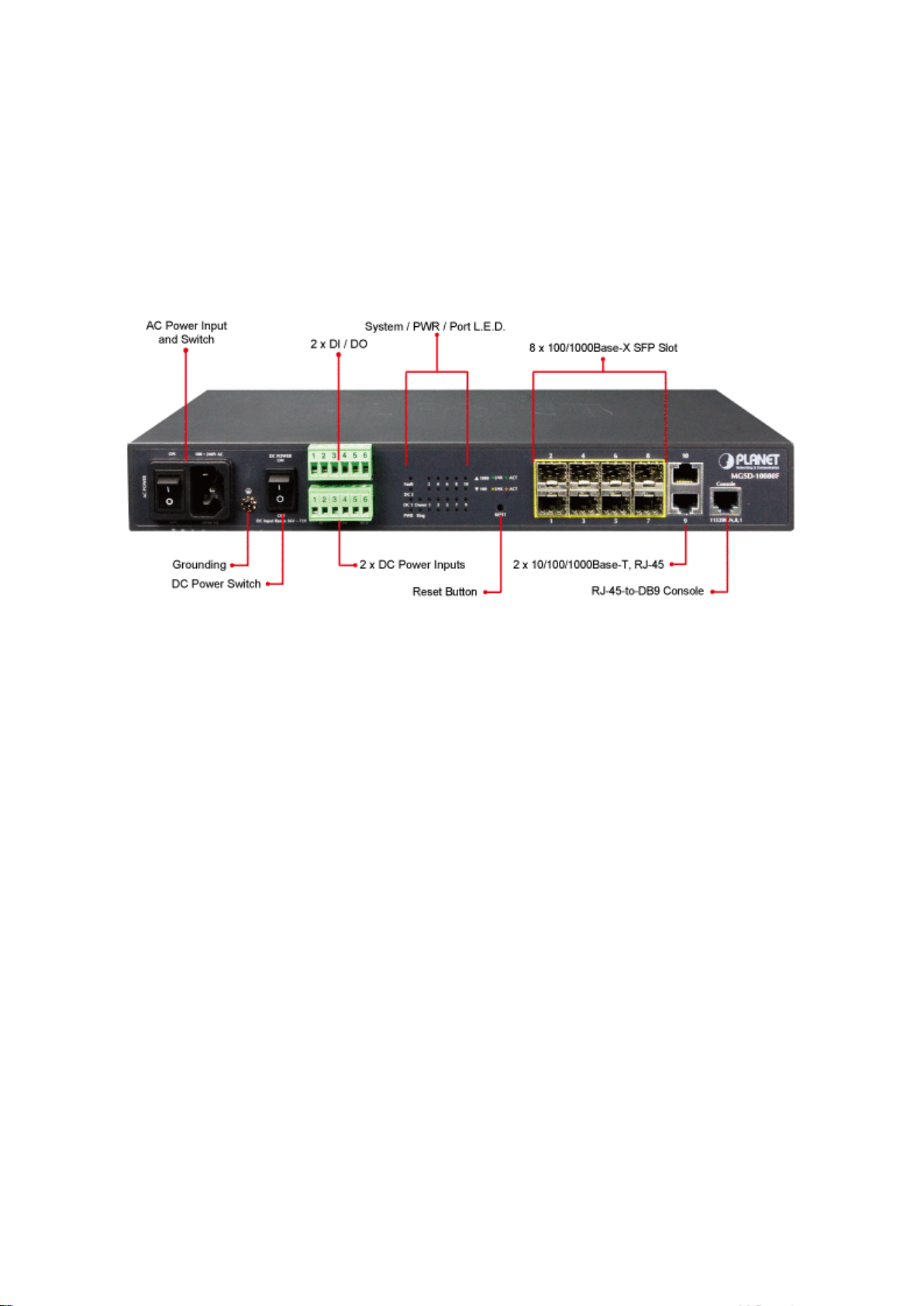
User’s Manual of MGSD-10080F
25
1.2 Product Descriptions
Multiple SFP Fiber Port Switch for Growing Long-Reach Networking of Enterprise, Telecoms and Campus
The MGSD-10080F is equipped with advanced management functions and provides 8 100/1000Mbps dual speed SFP Fiber
ports, and 2 10/100/1000Mbps TP ports delivered in a rugged strong case. It is capable of providing non-blocking switch fabr ic
and wire-speed throughput as high as 20Gbps in the temperature range from -10 to 60 degrees C without any packet loss and
CRC error, which greatly simplify the tasks of upgrading the enterprise LAN for catering to increasing bandwidth demands. The
MGSD-10080F is specially designed for service provider to deliver profitable Ethernet network. The MGSD-10080F adopts
“Front Access” design, making the wiring and m aintenance of the MGSD-10080F placed in a cabinet very easy for technicians.
AC and DC Redundant Power to ensure continuous operation
PLANET MGSD-10080F is equipped with one 100~240V AC power supply unit and one additional 36 ~ 72V DC power supply
unit for redundant power supply installation. A redundant power system is also provided to enhance the reliability with either the
100~240V AC power supply unit or the DC 36 ~ 72V power supply unit. Redundant Power Systems are specifically designed to
handle the demands of hi gh te ch fa cil iti es re quiring the highest pow er int egr ity. Furthermore, with the 36~ 72V DC power supply
implemented, the MGSD-10080F can be applied as the telecom level device that could be located in the electronic room.
Digital Input and Digital Output for external Alarm
PLANET MGSD-10080F supports Digital Input, and Digital Output on the front panel. This external alarm offers technicians the
ability to use Digital Input to detect, and log external device status (such as door intrusion detector ) for the alarm. As Digital
Output could be used to alarm if MGSD-10080F has port link down, link up or power failure.
Page 26
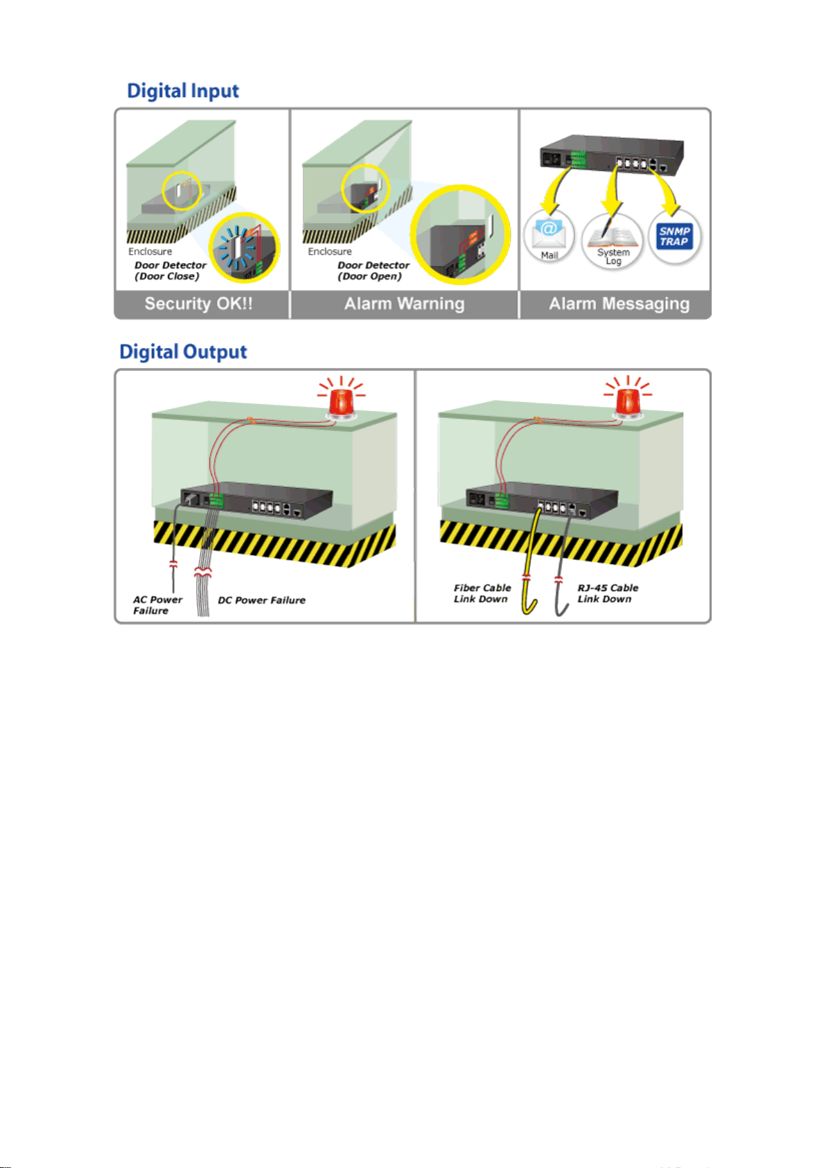
User’s Manual of MGSD-10080F
26
Cost-effective IPv6 Managed Gigabit Switch solution for Metro
Nowadays, lots of electronic products or mobile devices can browse the Internet, which means the need of IP Address
increases. However, the current IPv4 network infrastructure is not capable enough to provide IP Address to each single
user/client. The situation forces the ISP to come out with the IPv 6 (Internet Protocol version 6) network infrastructure. To fulfill
the demand, PLANET releases the IPv6 management Gigabit Ethernet Switch. It supports both IPv4 and IPv6 management
functions. It can work with original network structure (IPv4) and also support the new network structure (IPv6). With easy and
friendly management interfaces and plenty of management functions included, th e MGSD-10080F Managed Switch is the best
choice for you to build the IPv6 FTTx edge service and for Industries to connect with IPv6 network.
Layer 2 / Layer 4 Full-functioned Managed Switch for Building Automation Networking
The MGSD-10080F Metro Managed Ethernet Switch is ideal for applicat ion s in the factory data centers and distributions. It
provides advanced Layer 2 to Layer 4 data switching and redundancy, Quality of Service traffic control, networ k access co ntrol
and authentication, and Secure Management features to protect customer’s industrial network connect iv ity w ith reliable
switching recovery capability that is suitable for implementing fault tolerant and mesh network architectures.
Powerful Security
The Managed Switch offers comprehensive Access Control List (ACL) for enforcing security to the edge. Its protection
mechanisms also comprise port-based 802.1x and MAC-based user and device authentication. The port-security is effective in
limit the numbers of clients pass through, so that network administrators can now construct highly secured corporate networks
with time and effort considerably less than before.
Page 27
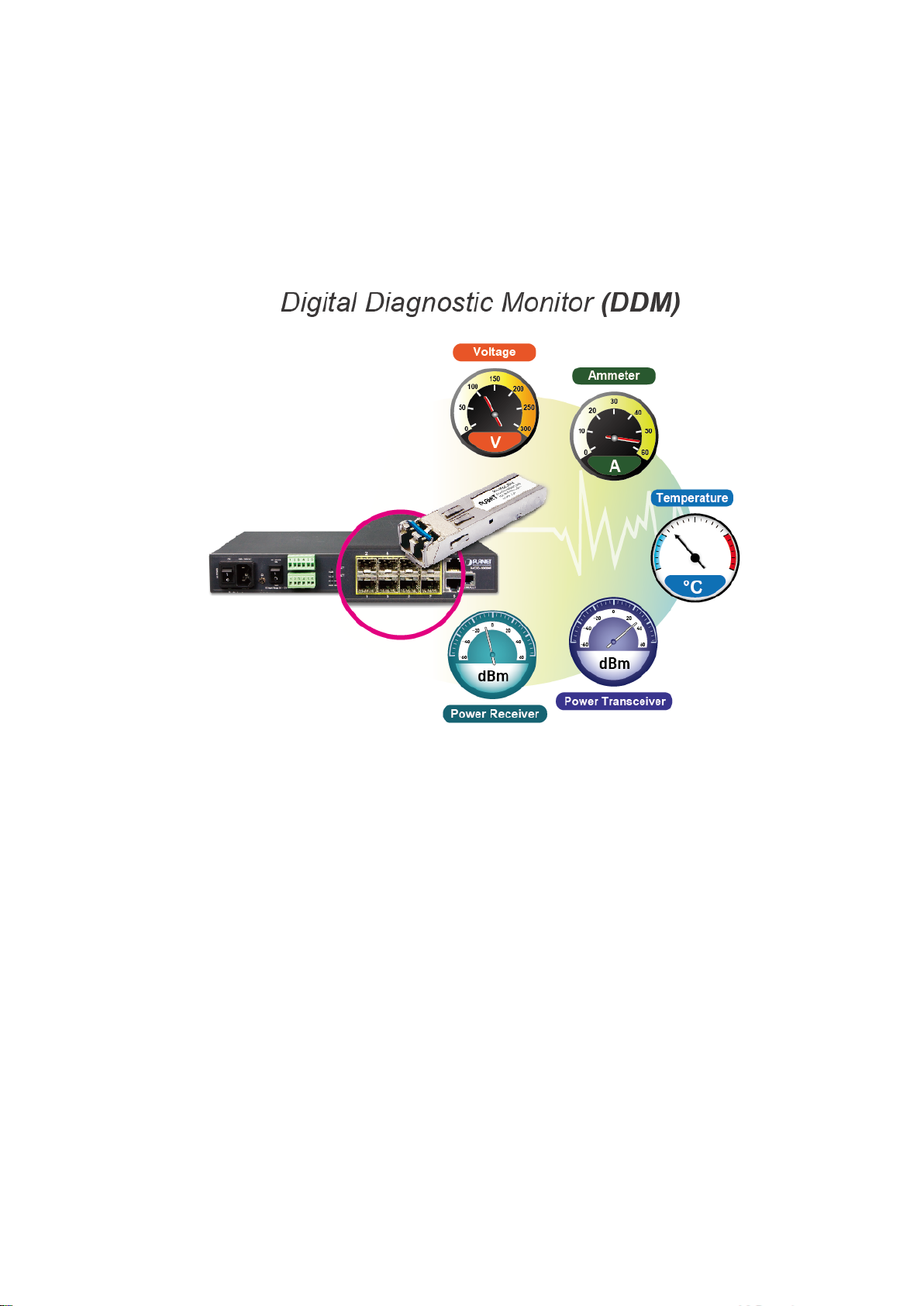
User’s Manual of MGSD-10080F
27
Flexible and Extendable Solution
The 8 mini-GBIC slots built in the IGS-10080MFT support Dual-Speed, 100Base-FX and 1000Base-SX/LX SFP (Small
Form-factor Pluggable) fiber-optic modules, meaning the administrator now can flexibl y choose the suitable SFP transceiver
according to the transmission dist anc e or the transmission speed required to extend the network efficiently. The MGSD-10080F
supports SFP-DDM (Digita l Diagnostic Monitor) function that can easily monitor real-time parameters of the SFP for network
administrator, such as optical output power, optic al inp ut po wer, temperatur e, la ser bia s cur rent, and transceiver supply volt age.
1.3 How to Use This Manual
This User Manual is structured as follows:
Section 2, INSTALLATION
The section explains the functi ons of the Managed Switch and how to physically install the Managed Switch.
Section 3, SWITCH MANAGEMENT
The section contains the information about the software function of the Managed Switch.
Section 4, WEB CONFIGURATION
The section explains how to manage the Managed Switch by Web interface.
Section 5, COMMAND LINE INTERFACE
The section describes how to use the Command Line interface (CLI).
Section 6, CLI MODE
The section explains how to manage the Managed Switch by Command Line interface.
Page 28

28
Section 7, SWITCH OPERATION
The chapter explains how to do the switch operation of the Managed Switch.
Section 8, TROUBLESHOOTING
The chapter explains how to do troubleshooting of the Managed Switch.
Appendix A
The section contains cab le inf or mat ion of the Managed Switch.
Appendix B
The section contains glossary information of the Managed Switch.
User’s Manual of MGSD-10080F
Page 29

29
1.4 Product Features
Physical Port
8 100/1000Base-X SFP mini-GBIC slots
2-Port 10/100/1000Base-T Gigabit Ethernet RJ-45
One RJ-45 Console Interface for Basic Management and Setup
Redundant Power System
Redundant Power System: 100V ~ 240 V AC / Dual 36V ~ 72V DC
Active Redundant Power Failure Protection
Backup of Catastrophic Power Failure on One Supply
Fault Tolerance and Resilience.
Digital Input / Digital Output
2 Digital Input (DI)
User’s Manual of MGSD-10080F
2 Digital Output (DO)
Integrates sensors into Auto Alarm System
Transfer Alarm to IP Network via SNMP Trap
Hardware Design
-10 to 60 Degrees C Operating Temperature for DC Power Input only
19-inch Rack-mountable
Relay Alarm for Port Breakdown, Power Failure
Fanless Design
Layer 2 Features
Prevents Packet Loss with Back Pressure (Half-Duplex) and IEEE 802.3x PAUSE Frame Flow Control (Full-Duplex)
High Performance of Store-and-Forward Architecture and Runt/CRC Filtering Eliminate Erroneous Packets to
Optimize the Network Bandwidth
Storm Control Support
− Broadcast / Multicast / Unicast
Supports VLAN
− IEEE 802.1Q Tagged VLAN
− Up to 255 VLANs Groups, Out of 4094 VLAN IDs
− Provider Bridging (VLAN Q-in-Q) Support (IEEE 802.1ad)
− Private VLAN Edge (PVE)
− Protocol-based VLAN
− MAC-based VLAN
− Voice VLAN
Supports Spanning Tree Protocol
− STP, IEEE 802.1D Spanning Tree Protocol
Page 30

30
− RSTP, IEEE 802.1w Rapid Spanning Tree Protocol
− MSTP, IEEE 802.1s Multiple Spanning Tree Protocol, Spanning Tree by VLAN
− BPDU Guard
Supports Link Aggregation
− 802.3ad Link Aggregation Control Protocol (LACP)
− Cisco Ether-channel (Static Trunk)
− Maximum 5 trunk Groups, up to 8 ports per Trunk Group
− Up to 16Gbps Bandwidth (Duplex Mode)
Provides Port Mirror (1-to-1)
Port Mirroring to Monitor the Incoming or Outgoing Traffi c on a Particular Port
Loop Protection to Avoid Broadcast Loops
Supports E.R.P.S. (Ethernet Ring Protection Switching)
Quality of Service
Ingress Shaper and Egress Rate Limit Per Port Bandwidth Control
8 Priority Queues on All Switch Ports
Traffic Classification
- IEEE 802.1p CoS
- IP TOS / DSCP / IP Precedence
- IP TCP/UDP Port Number
- Typical Network Application
Strict Priority and Weighted Round Robin (WRR) CoS Policies
Supports QoS and In/Out bandwidth Control on Each Port
Traffic-Policing Policies on the Switch Port
User’s Manual of MGSD-10080F
DSCP Remarking
Multicast
Supports IGMP Snooping v1, v2 and v3
Supports MLD Snooping v1 and v2
Querier Mode Support
IGMP Snooping Port Filtering
MLD Snooping Port Filtering
MVR (Multicast VLAN Registration)
Security
IEEE 802.1x Port-based / MAC-based Network Access Authentication
Built-in RADIUS Client to co-operate with the RADIUS Servers
RADIUS / TACACS+ Users Access Authentication
IP-Based Access Contr ol List (ACL)
MAC-Based Access Control List
Source MAC / IP Address Binding
Page 31

User’s Manual of MGSD-10080F
31
DHCP Snooping to Filter Untrusted DHCP Messages
Dynamic ARP Inspection discards ARP Packets with Inv ali d M AC Address to IP Address Binding
IP Source Guard prevents IP spoofing att a ck s
IP Address Access Management to Prevent Unauthorized Intruder
Management
Switch Management Interfaces
- Console / Telnet Command Line Interface
- Web Switch Management
- SNMP v1 and v2c Switch Management
- SSH / SSL and SNMP v3 Secure Access
Four RMON Groups (History, Statistics, Alarms, and Events)
IPv6 IP Address / NTP / DNS Management
Built-in Trivial File Transfer Protocol (TFTP) Client
BOOTP and DHCP for IP Address Assignment
Firmware Upload / Download via HTTP / TFTP
DHCP Relay
DHCP Option 82
User Privilege Levels Control
NTP (Network Time Protocol)
Link Layer Discovery Protocol (LLDP) Protocol
SFP-DDM (Digital Diagnostic Monit or)
Cable Diagnostic technology provides the mechanism to detect and report potential cabling issues
Reset Button for System Reboot or Reset to Factory Default
PLANET Smart Discovery Utility for Deploy Management
Page 32

32
Throughput (Packet per second)
Back Pressure for Half-Duplex
> 10 seconds: Factory Default
Pin 1/2 for DI 1 & 2; Pin 3/4 for DO 1 & 2; Pin 5/6 for GND
Dimensions (W x D x H)
330 x 155 x 43.5 mm, 1U high
Weight
1661g
System:
1000 LNK/ACT (Green)
Max. 10.8 Watts / 36.9 BTU (DC input)
bility: 1A @ DC 24V
2 Digital Output (DO): Open Collector to 24VDC, 100mA max.
1.5 Product Specifications
User’s Manual of MGSD-10080F
Product
Hardware Specificati ons
SFP/Mini-GBIC Slots
Copper Ports
Console Port
Switch Architecture
Switch Fabric
Address Table
Share Data Buffer
Flow Control
Jumbo Frame
Reset Button
MGSD-10080F
8 1000Base-SX/LX/BX SFP Interfaces
Compatible with 100Base-FX SFP
2 10/ 100/1000Base-T RJ-45 Auto-MDI/MDI-X Ports
1 x RJ-45-to-RS-232 Serial Port (115200, 8, N, 1)
Store-and-Forward
14.8Mpps @ 64Bytes Packet
20Gbps / Non-Blocking
8K Entries, Automatic Source Address Learning and Ageing
4Mbits
IEEE 802.3x Pause Frame for Full-Duplex
9Kbytes
< 5 seconds: System Reboot
Connector
LED Indicator
Power Consumption
Power Requirements
Alarm
Removable 6-pin terminal block for power input
Pin 1/2 for Power 1; Pin 3/4 for fault alarm; Pin 5/6 for Power 2
Removable 6-pin terminal block for DI/DO interface
PWR (Green)
DC 1 (Green)
DC 2 (Green)
Fault Alarm (Green)
Ring (Green)
Ring Owner (Green)
Per Gigabit Ports:
100 LNK/ACT (Orange)
Max. 11.2 Watts / 38.2 BTU (AC input)
AC 100~240V, 50/60Hz 0.15A
-36V DC @ 0.3A, Range: -36V ~ -72V DC
One Relay Output for Power failure. Alarm Relay Current Carry A
2 Digital Input (DI): Level 0: -24V~2.1V (±0.1V)
DI/DO
Layer 2 Function
Level 1: 2.1V~24V (±0.1V)
Input Load to 24V DC, 10mA max.
Page 33

33
Power Saving Mode Control
Auto Negotiation Status, Trunk Status.
1 to 1 Monitor
Up to 255 VLAN Groups, Out of 4094 VLAN IDs
Supports 5 Groups of 8-Port trunk Support
- DSCP/TOS Field in IP Packet
IGMP Querier Mode Support
MLD Querier Mode Support
Up to 123 Entries
Egress: 500Kb~1000Mbps
RFC-2618 RADIUS Client MIB
Port Configuration
User’s Manual of MGSD-10080F
Port Disable / Enable
Auto-Negotiation 10/100/1000Mbps Full and Half Duplex Mode Selection
Flow Control Disable / Enable
Bandwidth Control on Each Port
Port Status
Port Mirroring
VLAN
Link Aggregation
QoS
Display Each Port’s Speed Duplex Mode, Link Status, Flow Control Status.
TX / RX / Both
802.1Q Tagged based VLAN, up to 255 VLAN Groups
Q-in-Q Tunneling
Private VLAN Edge (PVE)
MAC-based VLAN
Protocol-based VLAN
Voice VLAN
MVR (Multicast VLAN Registration)
IEEE 802.3ad LACP / Static Trunk
Traffic Classification based, Strict Priority and WRR
8-Level Priority for Switching
- Port Number
- 802.1p Priority
- 802.1Q VLAN Tag
IGMP Snooping
MLD Snooping
Access Control List
Bandwidth Control
Management
Basic Management Interfaces
Secure Management Interfac e
SNMP MIBs
IGMP (v1/v2/V3) Snooping, up to 255 Multicast Groups
MLD (v1/v2) Snooping, up to 255 Multicast Groups
IP-based ACL / MAC-based ACL
Per Port Bandwidth Control
Ingress: 500Kb~1000Mbps
Console, Telnet, Web Browser, SNMPv1, v2c and v3
SSH, SSL, SNMP v3
RFC-1213 MIB-II
IF-MIB
RFC-1493 Bridge MIB
RFC-1643 Ethernet MIB
RFC-2863 Interface MIB
RFC-2665 Ether-Like MIB
RFC-2819 RMON MIB (Group 1)
RFC-2737 Entity MIB
Page 34

34
MAU-MIB
Environment
Relative Humidity: 5 ~ 95% (Non-condensing)
Relative Humidity: 5 ~ 95% (Non-condensing)
Standards Conformance
User’s Manual of MGSD-10080F
RFC-2933 IGMP-STD-MIB ()
RFC3411 SNMP-Frameworks-MIB
IEEE802.1X PAE
LLDP
Regulation Compliance
Standards Compliance
FCC Part 15 Class A, CE
IEEE 802.3 10Base-T
IEEE 802.3u 100Base-TX/100Base-FX
IEEE 802.3z Gigabit SX/LX
IEEE 802.3ab Gigabit 1000T
IEEE 802.3x Flow Control and Back Pressure
IEEE 802.3ad Port trunk with LACP
IEEE 802.1D Spanning Tree Protocol
IEEE 802.1w Rapid Spanning Tree Protocol
IEEE 802.1s Multiple Spanning Tree Protocol
IEEE 802.1p Class of Service
IEEE 802.1Q VLAN Tagging
IEEE 802.1x Port Authentication Network Control
IEEE 802.1ab LLDP
RFC 768 UDP
RFC 793 TFTP
RFC 791 IP
RFC 792 ICMP
RFC 2068 HTTP
RFC 1112 IGMP version 1
RFC 2236 IGMP version 2
Operating
Storage
Temperature: -10 ~ 60 degrees C for DC power input.
0 ~ 50 degrees C for AC power input.
Temperature: -10 ~ 70 degrees C
Page 35

User’s Manual of MGSD-10080F
35
2. INSTALLATION
2.1 Hardware Descriptions
The Managed Switch provides three different running speeds – 10Mbps, 100Mbps and 1000Mbps in the same Switch and
automatically distinguishes the speed of incoming connection. This section describes the hardware features of M anaged Switch.
For easier management and control of the Managed Switch, familiarize yourself with its display indicators, and ports. Front
panel illustrations in this chapter display the unit LED indicators. Before connecting any network device to the Managed Switch,
read this chapter carefully.
2.1.1 Front Panel
Figure 2-1 shows a front panel of Managed Switch.
Figure 2-1: MGSD-10080F Switch Front Panel
■ Gigabit TP interface
10/100/1000Base-T Copper, RJ-45 Twist-Pair: Up to 100 meters.
■ Gigabit SFP slots
1000Base-SX/LX mini-GBIC Slot, SFP (Small Factor Pluggable) Transceiver Module: fr o m 550 meter s (M ulti-mode Fiber),
up to 10/30/50/70/120 kilometers (Single-mode Fiber).
■ Console Port
The console port is a RJ-45 port connector. It is an interface for connecting a terminal directly. Through the console port, it
provides rich diagnostic information including IP Address setting, factory reset, port management, link status and system
setting. Users can use the attached DB9 to RJ-45 console cable in the package and connect to the console port on the
device. Af ter the con nec tio n, users can run any terminal emulation program (Hyper Terminal, ProComm Plus, Telix,
Winterm and so on) to enter the startup screen of the device.
■ Reset Button
At the front panel, the reset button is designed for rebooting the Managed Switch without turning off and on the power. The
following is the summary table of reset button functions:
Page 36

User’s Manual of MGSD-10080F
36
Reset Button Pressed and Released
Function
Default Gateway: 192.168.0.254
back to the factory default
Power Supply) for your device.
Switch from being damaged by unregulated
< 5 sec: System Reboot Reboot the Managed Switch
Reset the Managed Switch to Factory Default configuration.
The Managed Switch will then reboot and load the default
settings as below:
> 5 sec: Factory Default
。 Default Username: admin
。 Default Password: admin
。 Default IP address: 192.168.0.100
。 Subnet mask: 255.255.255.0
。
Figure 2-2: Reset button of Managed Switch
1. Press the RESET but ton onc e. The Managed Switch will reboot automatically.
2. Press the RESET button for 5 seconds. The Managed Switch will be
mode; the entire configuration will be erased.
■ AC Power Receptacle
For compatibility with electric service in most areas of the world, the Managed Switch’s power supply automatically adjusts
to line power in the range of 100-240V AC and 50/60 Hz.
Plug the female end of the power cord firmly into the receptalbe on the front panel of the Managed Switch. Plug the other
end of the power cord into an electric service outlet and then the power will be ready.
The device is a power-required device, which means it will not work till it is powered. If your networks
should be active all the time, please consider using UPS (Uninterrupted
Reset Button
Power Notice:
■ DC Power Connector
The front panel of the Managed Switch contains a power switch and a DC power connector, which accepts DC power input
voltage from -36V to -72V DC. Connect the power cable to the Managed Switch at the input terminal block. The size of the
two screws in the terminal block is M3.5.
It will prevent you from network data loss or network downtime. I n some area s, installing a surge
suppression device may also help to protect your Managed
surge or current to the Switch or the power adapter .
Page 37

User’s Manual of MGSD-10080F
37
with speed
■ Digital Input
The digitail input of the Managed Switch can be activated by the external sensor that senses physical changes. These
changes can include intrusion detection or certain physical change in the monitored area. For examples, the external
sensor can be a door switch or an infrared motion detector.
■ Digital Output
The digital output main function is to allow the Managed Switch to trigger external devices, either automatically or by
remote control from a human operator or a software application.
2.1.2 LED Indications
System
LED Color Function
PWR Green
DC1 Green
DC2 Green
Fault Green
Lights to indicate that the Switch is powered on by A C input.
Lights to indicate that the Switch is powered on by DC1 inpu t.
Lights to indicate that the Switch is powered on by DC2 inpu t.
Lights to indicate that Switch AC/DC or port has failed.
Ring Green Lights to indicate that the ERPS Ring has been created successfully.
R.O. Green Lights to indicate that Switch has been enabled Ring Owner.
Per SFP Interface
LED Color Function
Lights: To indicate the link through that port i s su cce ssfully establi shed with speed
1000Mbps.
1000
Green
LNK/ACT
Blink: To indicate that the switch is actively sending or receiving data over that port.
Off: If L100 NK/ACT LED light-> indicate that the port is operating at 100Mbps.
If LNK/ACT LED Off -> ind ica te that the port is link down.
Lights: To indicate the link through that port is successfully established
100Mbps.
100
Orange
LNK/ACT
Per 10/100/1000Base-T Interface
Blink: To indicate that the switch is actively sending or receiving data over that port.
Off: If 1000 LNK/ACT LED light-> indicate that the port is operating at 1000Mbps
If 1000 LNK/ACT LED Off -> indicate that the port is link down.
Page 38

User’s Manual of MGSD-10080F
38
d
LED Color Function
Lights: To indicate the link through that port i s su cce ssfully establi shed with speed
1000Mbps.
1000
Green
LNK/ACT
10/100
Orange
LNK/ACT
Blink: To indicate that the switch is actively sending or receiving data over that port.
Off: If L10/100 NK/ACT LED light-> indicate that the port is operating at 10Mbps or
100Mbps.
If LNK/ACT LED Off -> ind ica te that the port is link down.
Lights: To indicate the link through that port is successfully established with spee
10Mbps or 100Mbps.
Blink: To indicate that the switch is actively sending or receiving data over that port.
Off: If 1000 LNK/ACT LED light-> indicate that the port is operating at 1000Mbps
If 1000 LNK/ACT LED Off -> indicate that the port is link down.
2.1.3 Wiring the AC Power Input
The front panel of the MGSD-10080F indicates an AC inlet power socket, which accepts input power from 100 to 240V AC,
50/60Hz.
Page 39

User’s Manual of MGSD-10080F
39
2.1.4 Wiring the DC Power Input
The 6-contact terminal blo ck connector on the front panel of MGSD-10080F is used for two DC redundant powers input. Please
follow the steps below to insert the power wire.
1. Insert positive / negative DC power wires into the contacts 1 and 2 for DC POWER 1, or 5 and 6 for DC POWER 2.
Figure 2-3: MGSD-10080F Upper Panel
Page 40

40
1 2 3 4 5 6 DC 1
DC 2
+ - +
-
2. Tighten the wire-clamp screws for preventing the wires from losing.
Figure 2-4 6-Pin Terminal Block Power Wiring Input
1. The wire gauge for the terminal block should be in the range of 12 ~ 24 AWG.
2. When performing any of the procedures like inserting the wires or tighten the wire-clamp screws,
make sure the power is OFF to prevent from getting an electric sho ck.
User’s Manual of MGSD-10080F
2.1.5 Wiring the Faulty Alarm Contact
The fault alarm contacts are in the middle (3 & 4) of the terminal block con nector as the p ictu re shows bel ow. Inserting the wires,
the Managed Switch will detect the fault status of the power failure, or port link failure (available for managed model). The
following illustration shows an application example for wiring the fault alarm contacts
Insert the wires into the faulty alarm contacts
1. The wire gauge for the terminal block should be in the range of 12 ~ 24 AWG.
2. When performing any of the procedures like inserting the wires or tighten the wire-clamp screws, make
sure the power is OFF to prevent from getting an electric shock.
Page 41

User’s Manual of MGSD-10080F
41
1 2 3 4 5
6
DI DO GND
2.1.6 Wiring the Digital Input / Output
The 6-contact terminal block connector on the front panel of MGSD-10080F is used for Digital Input and Digital Output. Please
follow the steps below to insert wire.
1. The MGSD-10080F offers two DI and DO groups. 1 and 2 are DI groups, 3 and 4 are DO groups and 5 and 6 are GND
(ground).
Figure 2-5 Wiring the Redundant Power Inputs
2. Tighten the wire-clamp screws for preventing the wires from loosening.
DI0 DI1 DO0 DO1 GND GND
Figure 2-6 6-Pin Terminal Block DI / DO Wiring Input
3. There are two Digital Input groups for you to monitor two different devices. The following topology shows how to wire DI0
and DI1. We use the MGSD-10080F to be an example for describing DI application.
Page 42

User’s Manual of MGSD-10080F
42
Figure 2-7 Wires DI0 and DI1 to Open Detector
4. There are two Digital Output groups for you to sense MGSD-10080F port failure or power failure and issue a high or low
signal to external device. The following topology shows how to wire DO0 and DO1.
Page 43

User’s Manual of MGSD-10080F
43
Figure 2-8 Wires DO0 and DO1 to Open Detector
Page 44

User’s Manual of MGSD-10080F
44
45 tips. For more
2.2 Install the Managed Switch
This section describes how to install your Managed Switch and make connectio ns to the Managed Switch. Please read the
following topics and perform the procedure s i n t he or de r b eing presented. To install your Ma naged Switch on a desktop or shelf,
simply complete the following step s.
In this paragraph, we will describe how to install the Managed Swi tch and the installation points attended to it.
2.2.1 Desktop Installation
To install the Managed Switch on desktop or shelf, please follow these steps:
Step1: Attach the rubber feet to the recessed areas on the bottom of the Managed Switch.
Step2: Place the Managed Switch on the desktop or the shelf near an AC/DC power source as shown in Figure 2-4.
Figure 2-4 Place the Managed Switch on the Desktop
Step3: Keep enough ventilation space between the Managed Switch and the surrounding objects.
Step4: Connect the Managed Sw itch to network devices.
Connect one end of a standard network cable to the 10/100/1000 RJ-45 ports on the front of the Managed Switch.
Connect the other end of the cable to the network devices such as printer servers, workstations or routers, etc.
Connecting to the Managed Switch requires UTP Category 5 network cabling with RJinformation, please see the Cabling Specification in Appendix A.
Step5: Supply power to the Managed Switch.
Connect one end of the power cable to the Managed Switch.
Connect the power plug of the power cable to a standard wall outlet.
When the Managed Switch receives power, the Power LED should remain solid Green.
Page 45

User’s Manual of MGSD-10080F
45
You must use the screws supplied with the mounting brackets. Damage caused to the parts by
2.2.2 Rack Mounting
To install the Managed Switch in a 19-inch standard rack, please follow the instructions described below.
Step1: Place the Managed Switch on a hard flat surface, with the front panel positioned towards the front side.
Step2: Attach the rack-mount bracket to each side of the Managed Switch with supplied screws attached to the package.
Figure 2-5 shows how to attach brackets to one side of the Managed Switch.
Figure 2-5 Attach Brackets to the Managed Switch.
using incorrect screws would invalidate the warranty.
Step3: Secure the brackets tightly.
Step4: Follow the same steps to attach the second bracket to the opposite side.
Step5: After the brackets are attached to the Managed Switch, use suitable screws to securely attach the brackets to the rack
as shown in Figure 2-6.
Figure 2-6 Mounting the Managed Switch on a Rack
Step6: Proceeds with steps 4 and 5 of session 2.2.1 Desktop Installation to connect the network cabling and supply power to
the Managed Switch.
Page 46

User’s Manual of MGSD-10080F
46
Port Type
Cable Type
Connector
10Base-T
Cat 3, 4, 5, 2-pair
RJ-45
100Base-TX
Cat.5 UTP, 2-pair
RJ-45
1000Base-T
Cat.5/5e/6 UTP, 2-pair
RJ-45
100Base-FX
50 / 125µm or 62.5 / 125µm multi-mode 9 / 125µm single-mode
LC (multi/single mode)
1000Base-SX/LX
50 / 125µm or 62.5 / 125µm multi-mode 9 / 125µm single-mode
LC (multi/single mode)
2.3 Cabling
10/100/1000Base-T and 100Base-FX / 1000Base-SX/LX
All 10/100/1000Base-T ports come wit h Auto-Negotiation capability. They automatically support 1000Base-T, 100Base-TX
and 10Base-T networks. Users only need to plug a working network device into one of the 10/100/1000Base-T ports, and
then turn on the Managed Switch. The port will automatically runs in 10Mbps, 20Mbps, 100Mbps or 200Mbps and
1000Mbps or 2000Mbp s after the negotiation with the connected device.
The Managed Switch has eight SFP interfaces that support 100/1000Mbps dual speed mode (Optional multi-mode/
single-mode 100Base-FX/1000Base-SX/LX SFP module)
Cabling
Each 10/100/1000Base-T por t uses RJ-45 sockets -- si milar to phone j acks -- for connection of unshielded twisted-pair
cable (UTP). The IEEE 802.3/802.3u 802.3ab Fast/Gigabit Ethernet standard requires Category 5 UTP for 100Mbps
100Base-TX. 10Base-T networks can use Cat.3, 4, 5 or 1000Base-T use 5/5e/6 UTP (see table below). Maximum distance
is 100meters (328 feet). The 100Base-FX/1000Base-SX/LX S FP slo t is u sed as LC connector with optional SFP module.
Please see table below and know more about the cable specifications.
Any Ethernet devices like hubs/PCs can be connected to the Managed Switch by using straight-through wires. The two
10/100/1000Mbps ports are auto-MDI/MDI-X, wh i c h can be used on straight-through or crossover cable.
Page 47

User’s Manual of MGSD-10080F
47
2.3.1 Installing the SFP Transceiver
The sections describe how to insert an SFP tr a ns ceiv er into an SFP slo t.
The SFP transceivers are hot-pluggable and hot-swappable. You can plug in and out the transceiver to/from any SFP port
without having to power down the Managed Switch as Figure 2-9 shows below:
Figure 2-9: Plugging in the SFP Transceiver
Approved PLANET SFP Transceivers
PLANET Managed Switch supports 100/1000 dual mode with both single mode and multi-mode SFP transceivers. The
following list of approved PLANET SFP transceivers is correct at the time of publication:
Gigabit SFP Transceiver Modules
MGB-GT SFP-Port 1000Base-T Module
MGB-SX SFP-Port 1000Base-SX mini-GBIC module
MGB-LX SFP-Port 1000Base-LX mini-GBIC module
MGB-L30 SFP-Port 1000Base-LX mini-GBIC module-30km
MGB-L50 SFP-Port 1000Base-LX mini-GBIC module-50km
MGB-L70
SFP-Port 1000Base-LX mini-GBIC module-70km
MGB-L120
MGB-LA10
MGB-LB10
MGB-LA20
MGB-LB20
MGB-LA40
SFP-Port 1000Base-LX mini-GBIC module-120km
SFP-Port 1000Base-LX (WDM,TX:1310nm) mini-G BIC module-10km
SFP-Port 1000Base-LX (WDM,TX:1550nm) mini-G BIC module-10km
SFP-Port 1000Base-LX (WDM,TX:1310nm) mini-G BIC module-20km
SFP-Port 1000Base-LX (WDM,TX:1550nm) mini-G BIC module-20km
SFP-Port 1000Base-LX (WDM,TX:1310nm) mini-G BIC module-40km
Page 48

User’s Manual of MGSD-10080F
48
SFP
MGB-LB40
MGB-TSX
MGB-TLX
MGB-TL30
MGB-TL70
SFP-Port 1000Base-LX (WDM,TX:1550nm) mini-GBIC module-40km
SFP-Port 1000Base-SX mini-GBIC module - 550m (-40~75 degrees C)
SFP-Port 1000Base-LX mini-GBIC module - 10km (-40~75 degreesC)
SFP-Port 1000Base-LX mini-GBIC module - 30km (-40~75 degrees C)
SFP-Port 1000Base-LX mini-GBIC module - 70km (-40~75 degrees C)
Fast Ethernet SFP Transceiver Modules
MFB-FX
MFB-F20
MFB-F40
MFB-F60
MFB-FA20
MFB-FB20
SFP-Port 100Base-FX Transceiver (1310nm)-2km
SFP-Port 100Base-FX Transceiver (1310nm)-20km
SFP-Port 100Base-FX Transceiver (1310nm)-40km
SFP-Port 100Base-FX Transceiver (1310nm)-60km
SFP-Port 100Base-BX Transceiver (WDM,TX:1310nm)-20km
SFP-Port 100Base-BX Tr anscei ver (WDM,TX:1550nm)-20km
MFB-TFX
MFB-TF20
1000Base-SX/LX:
Before connecting the other switches, workstation or media converter.
1. Make sure both sides of the SFP transceiver are with the same media ty pe, f or ex ampl e, 1000Base-SX to 1000Base-SX,
1000Bas-LX to 1000Base-LX.
2. Check the fiber-optic cable type that matches the SFP transceiver model.
To connect to 1000Base-SX SFP transceiver, use the multi-mode fiber cable with one side being the male duplex LC
connector type.
To connect to 1000Base-LX SFP transceiver, use the single-mode fiber cable with one side being the male duplex LC
connector type.
SFP-Port 100Base-FX Transceiver (1310nm) -2km (-40~75 degrees C)
SFP-Port 100Base-FX Transceiver (1310nm) - 20km (-40~75 degrees C)
1. It is recommended to use PLANET SFPs on the Managed Switch. If you insert an
transceiver that is not supported, the Managed Switch will not recognize it.
2. Please choose the SFP transceiver which can be operated under -40~75 degrees C
temperature if the switch device is working in an 0~50 degrees C temperature environment.
Connecting the fiber cable
1. Attach the duplex LC connector on the network cable into the SFP transceiver.
2. Connect the other end of the cable to a device – switches with SFP installed, fiber NIC on a workstation or a media
converter.
3. Check the LNK/ACT LED of the SFP slot on the front of the Managed Switch. Ensure that the SFP transceiver is
operating correctly.
Page 49

User’s Manual of MGSD-10080F
49
the lever of the module and turning it to a horizontal
position. Directly pulling out the module could damage the module and the SFP module slot of the
100Base-FX:
Before connecting the other switches, workstation or media converter.
1. Make sure both sides of the SFP transceiver are with the same media type or WDM pair, for example, 100Base-FX to
100Base-FX, 100Base-BX20-U to 100Base-BX20-D.
2. Check the fiber-optic cable type that matches the SFP transceiver model.
To connect to MFB-FX SFP transceiver, use the multi-mode fiber cable with one side being the male duplex LC
connector type.
To connect to MFB-F20/F40/F60/FA20/FB20 SFP transceiver , use the single-mode fiber cable with one side being
the male duplex LC connector type.
Connecting the fiber cable
1. Attach the duplex LC connector on the network cable into the SFP transceiver.
2. Connect the other end of the cable to a device – switches with SFP installed, fiber NIC on a workstation or a media
converter.
3. Check the LNK/ACT LED of the SFP slot of the switch/converter. Ensure that the SFP transceiver is operating correctly.
4. Check the Link mode of the SFP port if the link fails. Co works with some fiber-NICs or media converters. Set the Link
mode to “100 Force” when needed.
2.3.2 Remove the Module
1. Make sure there is no network activity by checking w ith the ne twor k admini strator, or throu gh the man agement interf ace o f
the switch/converter (if available) to disable the port in advance.
2. Remove the Fiber Optic Cable gently.
3. Lift up the lever of the MGB module and turn it to a horizontal position.
4. Pull out the module gently through the lever.
Figure 2-10: How to Pull Out the SFP Transceiver Module
Never pull out the module without lifting up
Managed Switch.
Page 50

User’s Manual of MGSD-10080F
50
3. SWITCH MANAGEMENT
This chapter explains the methods that you can use to configure management access to the Managed Switch. It describes the
types of management applications and the communication and management protocols that deliver data between your
management device (workstation or personal computer) and the system. It also contains information about port connection
options.
This chapter covers the following topics:
Requirements
Management Access Overview
Remote Telnet Access
Web Management Access
SNMP Access
Standards, Protocols, and Related Reading
3.1 Requirements
Workstations of subscribers running Windows XP/2003, Vista, Windows 7, MAC OS X, Linux, Fedora, Ubuntu or
other platform compatible with TCP/IP protocols.
Workstation installed with Ethernet NIC (Network Interface Card)
Ethernet Port connect
• Network cables - Use standard network (UTP) cables with RJ45 connectors.
• The above Workstation is installed with WEB Browser and JAVA runtime environment Plug-in
It is recommended to use Internet Explore 7.0 or above to access Managed Switch.
Page 51

User’s Manual of MGSD-10080F
51
3.2 Management Access Overview
The Managed Switch gives you the flexibility to access and manage it using any or all of the following methods:
Remote Telnet Interface
Web browser Interface
An external SNMP-based network management application
The Remote Telnet and Web browser interface support are embedded in the Managed Switch software and are available for
immediate use. Each of these management methods has their own advantages. Table 3-1 compares the three management
methods.
Method Advantages Disadvantages
Remote
Telnet
Web Browser
SNMP Agent
• Text-based
• Telnet functionality built into Windows
XP/2003, Vista, Windows 7 operating
systems
• Can be accesses from any location
• Ideal for configuring the switch remotely
• Compatible with all popular browsers
• Can be accessed from any location
• Most visually appealing
• Communicates with switch functions at
the MIB level
• Based on open standards
Table 3-1: Comparison of Management Methods
• Security can be compromised (hackers need
only know the IP address)
• Security can be compromised (hackers need
only know the IP address and subnet mask)
• May encounter lag times on poor connections
• Requires SNMP manager software
• Least visually appealing of all three methods
• Some settings require calculations
• Security can be compromised (hackers need
only know the community name)
Page 52

User’s Manual of MGSD-10080F
52
3.3 CLI Mode Management
There are two ways for CLI mode management, one is remote telnet, and the other is operating from console port. Remote
telnet is an IP-based protocol, and console port is for user to operate the MGSD-10080F on local only, however their operation
is the same.
The command line user interface is for performing system administration, such as displaying statistics or changing option
settings. Using this method, you can access the Managed Switch remote telnet interface fr om perso nal co mput er, or
workstation in the same Ethernet environment as long as you know the current IP address of the Managed Switch.
Figure 3-1: Remote Telnet and Console Port Interface Management
In Windows system, you may click “Start”, then choose “Accessories”and “Command Prompt”. Please input “telnet
192.168.0.100” and press “enter’ from your keyboard. You will see the following screen (see Figure 3-2) appear.
Page 53

User’s Manual of MGSD-10080F
53
Figure 3-2: Remote Telnet Interface Main Screen of Managed Switch
For more information about using the Remote Telnet interface, refer to Chapter 5 Remote Telnet Interface Management.
Page 54

User’s Manual of MGSD-10080F
54
3.4 Web Management
The Managed Switch offers management features that al lo w users to manage the Managed Switch from anywhere on the
network through a standard browser such as Microsoft Internet Explorer. After you set up your IP address for the Managed
Switch, you can access the Managed Switch’s Web interface applications directly in your Web browser by entering the IP
address of the Managed Switch.
Figure 3-3: Web Management
You can then use your Web browser to list and manage the Managed Switch configuration para met er s from one ce ntral
location; the Web Management requires Microsoft Internet Explor er 7.0 or later.
Figure 3-4: Web Main Screen of Managed Switch
Page 55

User’s Manual of MGSD-10080F
55
3.5 SNMP-Based Network Management
You can use an external SNMP-based application to configure and manage the Managed Switch, such as SNMP Network
Manager, HP Openview Network Node Management (NNM) or What’s Up Gold. This management method requires the SNMP
agent on the Managed Switch and the SNMP Network Management Station to use the same community string. This
management method, in fact, uses two community strings: the get community string and the set community string. If the
SNMP N et-work management Stat ion only knows the set community string, it can read and write to the MIBs. However, if it only
knows the get community string, it can only read MIBs. The default getting and setting community strings for the Managed
Switch is public.
Figure 3-5: SNMP Management
3.6 PLANET Smart Discovery Utility
For easily listing the Managed Switch in your Ethernet environment, the Planet Smart Discovery Utility from user’s manual
CD-ROM is an ideal solution. T he following installation instructions are to guide you to running the Planet Smart Discovery Utility.
1.Deposit the Planet Smart Discovery Utility in administrator PC.
2. Run this utility and the following screen appears.
Figure 3-6: Planet Smart Discovery Utility Screen
Page 56

User’s Manual of MGSD-10080F
56
two LAN cards or above in the same administrator PC, choose different LAN card by
If there are
usinh the “Select Adapter” tool.
3. Press “Refresh” button for the currently connected devices in the discovery list as the screen shows
below:
Figure 3-7: Planet Smart Discovery Utility Screen
1. This utility shows all necessary information from the devices, such as MAC Address, Device Name, firmware version, and
Device IP Subnet address. It can also assign new password, IP Subn et addr e ss and description for the devices.
2. After setup is completed, press “Update Device”, “Up dat e Multi” or “Update All” button t o ta ke effect. The meaning of
the 3 buttons above are shown as below:
Update Device: use current setting on one single devi ce.
Update Multi: use current setting on choose multi-devices.
Update All: use current setting on w hole dev ic es in the li st.
The same functions mentioned above also can be finding in “Option” tools bar .
3. To click the “Control Packet Force Broadcast” function, it can allow assign new setting value to the Web Smart Switch
under a different IP subnet address.
4. Press “Connect to Device” button and the Web login screen appears in Figure 3-4.
5. Press “Exit” button to shutdown the planet Smart Discovery Utility.
Page 57

User’s Manual of MGSD-10080F
57
.0 or later version does not allow Java Applets to open sockets. The user has to
4. WEB CONFIGURATION
This section introduces the configuration and functions of the Web-based management.
About Web-based Management
The Managed Switch offers management features that al lo w users to manage the Managed Switch from anywhere on the
network through a standard browser such as Microsoft Internet Explorer.
The Web-Based Management supports Internet Explorer 7.0. It is based on Java Applets with an aim to reduce network
bandwidth consumption, enhance access speed and present an easy viewing screen.
By default, IE7
explicitly modify the browser setting to enable Java Applets to use network ports.
The Managed Switch can be configured through an Ethernet connection, making sure the manager PC must be set on the
same IP subnet address with the Managed Switch.
For example, the default IP address of the Managed Switch is 192.168.0.100, then the manager PC should be set at
192.168.0.x (where x is a number between 1 and 254, except 100), and the default subnet mask is 255.255.255.0.
If you have changed t he de faul t IP address of the Managed Switch to 192.168.1.1 with subnet mask 255.255.255.0 via console,
then the manager PC should be set at 192.168.1.x (where x is a number between 2 and 254) to do the relative configuration on
manager PC.
Figure 4-1-1: Web Management
Page 58

User’s Manual of MGSD-10080F
58
Logging on the Managed Switch
1. Use Internet Explorer 7.0 or above Web browser. Enter the factory-default IP addr es s to ac ces s the Web inter f ace . T he
factory-default IP Address is shown as follows:
http://192.168.0.100
2. When the following login screen appears, please enter the default username "admin" with password “admin” (or the
username/password you have changed via console) to login the main screen of Managed Switch. The login screen in
Figure 4-1-2 appears.
Figure 4-1-2: Login Screen
Default User name: admin
Default Password: admin
After entering the username and password, the main screen appears as shown in Figure 4-1-3.
Page 59

User’s Manual of MGSD-10080F
59
button, you need
Figure 4-1-3: Default Main Page
Now , you can use the Web manage ment inter face to cont inue the sw itch ma nageme nt or manage the Managed Switch by Web
interface. The Switch Menu on the left of the web page let you access all the commands and statistics the Managed Switch
provides.
1. It is recommended to use Internet Explore 7.0 or above to access Managed Switch.
2. The changed IP address take effe ct im med iate ly af t er c lic king on the Save
to use the new IP address to access the Web interface.
3. For security reason, please change and memorize the new password after this first setup.
4. Only accept command in lowercase letter under web interface.
Page 60

User’s Manual of MGSD-10080F
60
4.1 Main Web Page
The Managed Switch provides a Web-based browser interface for configuring and managing it. This interface allows you to
access the Managed Switch using the Web browser of your choice. This chapter describes how to use the Managed Switch’s
Web browser interface to configure and manage it.
Main Functions Menu
SFP Port Link Status
Copper Port Link Status
Panel Display
The web agent displays an image of the Managed Switch’s ports. The Mode can be set to display different information for the
ports, including Link up or Link down. Clicking on the image of a port opens the Port Statistics page.
The port states are illustrated as follows:
Help Button
State Disabled Link Down Link Up
RJ-45 Ports
SFP Ports
Figure 4-1-4: Main Page
Main Screen
Page 61

User’s Manual of MGSD-10080F
61
Main Menu
Using the onboard web agent, you can define system par am e ters, man age and con tr ol the Managed Switch, and all its ports,
or monitor network conditions. Via the Web-Management, the administrator can setup the Managed Switch by selecting the
functions those listed in the Main Function. The screen in Figure 4-1-5 appears.
Figure 4-1-5: Managed Switch Main Functions Menu
Page 62

User’s Manual of MGSD-10080F
62
4.2 System
Use the System menu items to display and configure basic administrative details of the Managed Switch. Under the System
the following topics are provided to configure and view the system information.
4.2.1 System Information
The System Info page provides information for the current device information. System Info page helps a switch administrator to
identify the hardware MAC address, software version and system uptime. The screen in Figure 4-2-1 appears.
The page includes the following fields:
Object Description
• Contact
• Name
• Location
• MAC Address
• Power
• Temperature
• System Date
The system contact co nfigured in Configuration | Sy s tem | Information | System Contact.
The system name configured in Configuration | System | Information | System Name.
The system location configured in Configuration | System | Information | System
Location.
The MAC Address of this Managed Switch.
The AC Power, Power 1 and Power 2 ON/OFF Status display.
The temperature shows current of the switch inside temperature status.
The current (GMT) system time and date. The system time is obtained through the
Figure 4-2-1: System Information Page Screenshot
Page 63

User’s Manual of MGSD-10080F
63
configured SNTP Server, if any.
• System Uptime
• Software Version
• Software Date
Buttons
Auto-refresh : Check this box to refresh the page automatically. Automatic refresh occurs every 3 seconds.
: Click to refresh the page.
The period of time the device has been operational.
The software version of the Managed Switch.
The date when the switch software was produced.
4.2.2 IP Configuration
The IP Configura tion includes t he IP Ad dress, S ubnet M ask and Gateway. The Configured column is used to view or change t he
IP configuration. Fill up the IP Address, Subnet Mask and Gateway for the device. The screen in Figure 4-2-2 appears.
Figure 4-2-2: IP Configuration Page Screenshot
The Current column is used to show the active IP configuration.
Object Description
• DHCP Client
Enable the DHCP client by checking this box. If DHCP fails and the configured IP
Page 64

User’s Manual of MGSD-10080F
64
address is zero, DHCP will retry. If DHCP server does not respond around 35 seconds
and the configured IP address is non-zero, DHCP will stop and the configured IP
settings will be used. The DHCP client will announce the configured System Name as
hostname to provide DNS lookup.
Buttons
• IP Address
• IP Mask
• IP Router
• VLAN ID
• DNS Server
• DNS Proxy
: Click to save changes.
: Click to undo any changes made locally and revert to previously saved values.
: Click to renew DHCP Client. This button is only available if DHCP Client is enabled.
Provide the IP address of this switch in dotted decimal notation.
Provide the IP mask of this switch dotted deci mal notation.
Provide the IP address of the router in dotted decimal notation.
Provide the managed VLAN ID. The allowed range is 1 through 4095.
Provide the IP address of the DNS Server in dotted decimal notation.
When DNS proxy is enabled, DUT will relay DNS requests to the current configured
DNS server on DUT, and reply as a DNS resolver to the client device on the network.
4.2.3 IPv6 Configuration
Configure the switch-managed IPv6 information on this page.
The Configured column is used to view or change the IPv6 configuration. The current column is used to show the active IP v 6
configuration. The screen in Figure 4-2-3 appears.
Figure 4-2-3: IPv6 Configuration Page Screenshot
Page 65

65
The page includes the following fields:
Object Description
User’s Manual of MGSD-10080F
• Auto Configuration
• Address
• Prefix
• Router
Enable IPv6 auto-configuration by checking this box. If system cannot obtain the
stateless address in time, the configured IPv6 settings will be used. The router
may delay responding to a router solicitation for a few seconds, the total time
needed to complete auto-configurati on can be sign ifi can tly longer.
Provide the IPv6 address of this switch. IPv6 address is in 128-bit records
represented as eight fields of up to four hexadecimal digits with a colon
separating each field (:). For example, 'fe80::215:c5ff:fe03:4dc7'. The symbol '::'
is a special syntax that can be used as a shorthand way of representing multiple
16-bit groups of contiguous zeros; but it can appear only once. It can also
represent a legally valid IPv4 address. For example, '::192.1.2.34'.
Provide the IPv6 Prefix of this switch. The allowed range is 1 to 128.
Provide the IPv6 gateway address of this switch. IPv6 address is in 128-bit
records represented as eight fields of up to four hexadecimal digits with a colon
separating each field (:). For example, 'fe80::215:c5ff:fe03:4dc7'. The symbol '::'
is a special syntax that can be used as a shorthand way of representing multiple
16-bit groups of contiguous zeros; but it can appear only once. It can also
represent a legally valid IPv4 address. . For example, '::192.1.2.34'.
Buttons
: Click to save changes.
: Click to undo any changes made locally and revert to previously saved values.
: Click to renew IPv6 Auto Configuration. This button is only available if IPv6 Auto Configuration is enabled.
4.2.4 Users Configuration
This page provides an overview of the current users. Currently the only way to login as another user on the web server is to
close and reopen the browser. After setup is completed, please press “Save” button to take effect. Please login web interface
with new user name and password, the screen in Figure 4-2-4 appears.
Page 66

66
The page includes the following fields:
Object Description
User’s Manual of MGSD-10080F
Figure 4-2-4: Users Configuration Page Screenshot
Buttons
• User Name
• Privilege Level
: Click to add a new user.
The name identifying the user.
The privilege level of the user. The allowed range is 1 to 15. If the privilege level
value is 15, it can access all groups, i.e. that is granted the fully control of the
device. But others value need to refer to each group privilege level. User's
privilege should be same or greater than the group privilege level to have the
access of that group. By default setting, almost group privilege level 5 has the
read-only access and privilege level 10 has the read-write access. And the
system maintenance (software upload, factory defaults and etc.) need user
privilege level 15. Generally, the privilege level 15 can be used for an
administrator account, priv ileg e level 10 for a sta ndar d user a ccount and privilege
level 5 for a guest account.
Add / Edit User
This page configures a user – add, edit or delete user.
Figure 4-2-5: Add / Edit User Configuration Page Screenshot
Page 67

67
administrator account, priv ileg e level 10 for a sta ndar d user a ccount and pr ivile ge
he
will restore to the default
The page includes the following fields:
Object Description
User’s Manual of MGSD-10080F
Buttons
• User Name
• Password
• Privilege Level
A string identifying the user name that this entry should belong to. The allowed
string length is 1 to 32. The valid user name is a combination of letters, numbers
and underscores.
The password of the user. The allowed string length is 0 to 32.
The privilege level of the user. The allowed range is 1 to 15. If the privilege level
value is 15, it can access all groups, i.e. that is granted the fully control of the
device. But others value need to refer to each group privilege level. User's
privilege should be same or greater than the group privilege level to have the
access of that group. By default setting, most groups privilege level 5 has the
read-only access and privilege level 10 has the read-write access. And the
system maintenance (software upload, factory defaults and etc.) need user
privilege level 15. Generally, the privilege level 15 can be used for an
level 5 for a guest account.
: Click to save changes.
: Click to undo any changes made locally and revert to previously saved values.
: Click to undo any changes made locally and return to the Users.
: Delete the current user. This button is not available for new configurations (Add new user)
Figure 4-2-6: User Configuration Page Screenshot
If you forget the new password after changing the default pas sword, please press the “Reset”
button on the front panel of the Managed Switch for over 10 seconds and then release it. T
current setting including VLAN will be lost and the Managed Switch
mode.
Page 68

User’s Manual of MGSD-10080F
68
4.2.5 Privilege Levels
This page provides an ov er v ie w of the privilege levels. After setup completed, please press “Save” button to take eff ect. Please
login web interface with new user name and password and the screen in Figure 4-2-7 appears.
Figure 4-2-7: Privilege Levels Configuration Page Screenshot
Page 69

69
User Privilege should be same or greater than the authorization Privilege level to
The page includes the following fields:
Object Description
User’s Manual of MGSD-10080F
• Group Name
• Privilege Level
The name identifying the privilege group. In most cases, a privilege level group
consists of a single module (e.g. LACP, RSTP or QoS), but a few of them
contains more than one. The following description defines these privilege level
groups in details:
System: Contact, Name, Location, Timezone, Log.
Security: Authentication, System Access Management, Port (contains
Dot1x port, MAC based and the MAC Address Limit), ACL, HTTPS,
SSH, ARP Inspection and IP source guard.
IP: Everything except 'ping'.
Port: Everything except 'VeriPHY'.
Diagnostics: 'ping' and 'VeriPHY'.
Maintenance: CLI- System Reboot, System Restore Default, System
Password, Configuration Save, Configuration Load and Firmware Load.
Web- Users, Privilege Levels and everything in Maintenance.
Debug: Only present in CLI.
Every group has an authorization Privilege level for the following sub groups:
Buttons
: Click to save changes.
: Click to undo any changes made locally and revert to previously saved values.
4.2.6 NTP Configuration
Configuration read-only
Configuration/execute read-write
Status/statistics read-only
Status/statistics read-write (e.g. for clearing of statistics).
have the access to that group.
Configure NTP on this page.
NTP is an acronym for Network Time Protocol, a network protocol for synchronizing the clocks of computer systems. NTP
uses UDP (data grams) as transport layer. You can specify NTP Servers and set GMT Time zone. The NTP Configuration
screen in Figure 4-2-8 appears.
Page 70

70
The page includes the following fields:
Object Description
User’s Manual of MGSD-10080F
Figure 4-2-8: NTP Configuration Page Screenshot
Buttons
• Mode
• Timezone
• Server #
: Click to save changes.
Indicates the NTP mode operation. Possible modes are:
Enabled: Enable NTP mode operation. When NTP mode operation is
enabled, the agent forwards NTP messages between the clients and the
server when they are not on the same subnet domain.
Disabled: Disable NTP mode operation.
Allow select the time zone according to current location of switch.
Provide the NTP IPv4 or IPv6 address of this switch. IPv6 address is in 128-bit
records represented as eight fields of up to four hexadecimal digits with a colon
separating each field (:).
For example, 'fe80::215:c5ff:fe03:4dc7'. The symbol '::' is a special syntax that
can be used as a shorthand way of representing multiple 16-bit groups of
contiguous zeros; but i t can a ppear only once. I t can a lso r epresen t a lega lly v alid
IPv4 address. For example, '::192.1.2.34'.
: Click to undo any changes made locally and revert to previously saved values.
Page 71

User’s Manual of MGSD-10080F
71
4.2.7 Daylight Saving
The Reboot page enables the device to be rebooted from a remote location. Once the Reboot button is pressed, user will
re-access the WEB interface about 60 seconds later, the System Reboot screen in Figure 4-2-9 appears.
The page includes the following fields:
Object Description
• Time Zone
• Acronm
• Daylight Saving Time
Figure 4-2-9: System Reboot Page Screenshot
Allow select the time zone according to current location of switch.
User can set the acronym of the time zone. This is a User configurable
acronym to identify the time zone. ( Range : Up to 16 alpha-numeric
characters and can contai n ' -', '_' or '.')
is is used to set the clock forward or backward according to the
configurations set below for a defined Daylight Saving Time duration.
Select 'Disable' to disable the Daylight Saving Time configuration. Select
'Recurring' and configure the Daylight Saving Time duration to repeat the
configuration every year. Select 'Non-Recurring' and configure the
Page 72

User’s Manual of MGSD-10080F
72
Daylight Saving Time duration for single time configuration. ( Default :
Daylight Saving Rime –
Object Description
• Week (Start Time Setting)
• Day (Start Time Setting)
• Month (Start Time Setting)
• Hours (Start Time Setting)
• Minutes (Start Time Setting)
• Week (End Time Setting)
• Day (End Time Setting)
• Month (End Time Setting)
• Hours (End Time Setting)
• Month (End Time Setting)
• Offest
Disabled )
Recurring Mode
Select the starting week number.
Select the starting day.
Select the starting month.
Select the starting hour.
Select the starting minute.
Select the ending week number.
Select the ending day.
Select the ending month.
Select the ending hour.
Select the ending minute.
Enter the number of minutes to add during Daylight Saving Time.
( Range: 1 to 1440 )
Daylight Saving Rime – Non-
Object Description
• Month (Start Time Setting)
• Date (Start Time Setting)
• Year (Start Time Setting)
• Hours (Start Time Setting)
• Minutes (Start Time Setting)
• Month (End Time Setting)
• Date (End Time Setting)
• Year (End Time Setting)
• Hours (End Time Setting)
• Minutes (End Time Setting)
• Offset
Recurring Mode
Select the starting month.
Select the starting date.
Select the starting year.
Select the starting hour.
Select the starting minute.
Select the ending month.
Select the ending date.
Select the ending year.
Select the ending hour.
Select the ending minute.
• Enter the number of minutes to add during Daylight Saving Time.
( Range: 1 to 1440 )
Buttons
: Click to save changes.
: Click to undo any changes made locally and revert to previously saved values.
Page 73

User’s Manual of MGSD-10080F
73
The duration, carried in SS DP packets, is used to inform a control point or cont rol
4.2.8 UPnP
Configure UPnP on this page.
UPnP is an acronym for Universal Plug and Play. The goals of UPnP are to allow devices to connect seamlessly and to
simplify the implementation of networks in the home (data sharing, communications, and entertainment) and in corporate
environments for simplified installation of computer components. The UPnP Configuration screen in Figure 4-2-10 appears.
Figure 4-2-10: UPnP Configuration Page Screenshot
The page includes the following fields:
Object Description
• Mode
• TTL
• Advertising Duration
Indicates the UPnP operation mode . Pos sible mod es are:
Enabled: Enable UPnP mode operation.
Disabled: Disable UPnP mode operation.
When the mode is enabled, two ACEs are added automatically to trap UPNP
related packets to CPU. The ACEs are automatically removed when the mode is
disabled.
The TTL value is used by UPnP to send SSDP advertisement messages. Valid
values are in the range of 1 to 255.
points how often it or they should receive a SSDP advertisement message from
this switch. If a control point does not receive any message within the duration, it
will think that the switch no longer exists. Due to the unreliable nature of UDP, in
the standard it is recommended that such refreshing of advertisements to be
done at less than one-half of the advertising duration. In the implementation, the
switch sends SSDP messages periodically at the interval one-half of the
advertising duration minus 30 seconds. Valid values are in the range 100 to
86400.
Buttons
: Click to save changes.
: Click to undo any changes made locally and revert to previously saved values.
Page 74

User’s Manual of MGSD-10080F
74
Figure 4-2-11: UPnP
Devices shows on Windows My Network Places
4.2.9 DHCP Relay
Configure DHCP Relay on this page. DHCP Relay is used to forward and to transfer DHCP messages between the clients and
the server when they are not on the same subnet domain.
The DHCP option 82 enables a DHCP relay agent to insert specific information into a DHCP request packets when forwarding
client DHCP packets to a DHCP server and remov e the specific information from a DH CP reply packets w hen f orwarding server
DHCP packets to a DHCP client. The DHCP server can use this information to implement IP address or other assignment
policies. Specifically the option works by setting two sub-options:
Circuit ID (option 1)
Remote ID (option2).
The Circuit ID sub-option is supposed to include information specific to which circuit the request came in on.
The Remote ID sub-option was designed to carry information relating to the remote host end of the circuit.
The definition of Circuit ID in the switch is 4 bytes in length and the format is "v lan_ id" "module_id" "port_no". The parameter of
"vlan_id" is the first two bytes representing the VLAN ID. The parameter of "module_id" is the third byte for the module ID (in
standalone switch it always equals 0, in stackable switch it means sw itch ID). T he p ara meter of "port_n o" is th e fourt h byte and it
means the port number.
Page 75

User’s Manual of MGSD-10080F
75
DHCP relay informa tion mo de oper ation, the age nt in sert sp ecifi c infor mation
contains relay agen t i nformation. It will enfor ce t he p oli cy. And it only works under
The Remote ID is 6 bytes in length, and the value is equal the DHCP relay agent’s MAC address. The DHCP Relay
Configuration screen in Figure 4-2-12 appears.
Figure 4-2-12: DHCP Relay Configuration Page Screenshot
The page includes the following fields:
Object Description
• Relay Mode
• Relay Server
• Relay Information
Mode
Indicates the DHCP relay mode operation. Possible modes are:
Enabled: Enable DHCP relay mode operation. When enable DHCP relay
mode operation, the agent forw ard and t o transfer DHCP messages betw een
the clients and the server when they are not on the same subnet domain.
And the DHCP broadcast message won't flood for security considered.
Disabled: Disable DHCP relay mode operation.
Indicates the DHCP relay server IP address. A DHCP relay agent is used to
forward and to transfer DHCP messages between the clients and the server
when they are not on the same subnet domain.
Indicates the DHCP relay information mode option operation. Possible modes
are:
Enabled: Enable DHCP relay information mode operation. When enable
(option82) into a DHCP message when forwarding to DHCP server and
remove it from a DHCP message when transferring to DHCP client. It only
works under DHCP relay operation mode enabled.
Disabled: Disable DHCP relay information mode operation.
• Relay Information
Policy
Indicates the DHCP relay information option policy. When enable DHCP relay
information mode operation, if agent receive a DHCP message that already
DHCP relay information operation mode enabled. Possible policies are:
Replace: Replace the original relay information when receiving a DHCP
message that already contains it.
Keep: Keep the original relay information when receiving a DHCP message
that already contains it.
Page 76

User’s Manual of MGSD-10080F
76
Drop: Drop the package when receiving a DHCP message that already
contains relay information.
Buttons
: Click to save changes.
: Click to undo any changes made locally and revert to previously saved values.
4.2.10 DHCP Relay Statistics
This page provides statistics for DHCP relay. The DHCP Relay Statistics screen in Figure 4-2-13 appears.
Figure 4-2-13: DHCP Relay Statistics Page Screenshot
The page includes the following fields:
Server Statistics
Object Description
• Transmit to Server
• Transmit Error
• Receive form Server
• Receive Missing Agent
Option
• Receive Missing
Circuit ID
• Receive Missing
Remote ID
The number of packets that are relayed from client to server.
The number of packets that resulted in errors while being sent to clients.
The number of packets received from server.
The number of packets received without agent information options.
The number of packets received with the Circuit ID option missing.
The number of packets received with the Remote ID option missing.
• Receive Bad Circuit ID
• Receive Bad Remote
ID
The number of packets whose Circuit ID option did not match known circuit ID.
The number of packets whose Remote ID option did not match known Remote
ID.
Page 77

77
Client Statistics
Object Description
User’s Manual of MGSD-10080F
• Transmit to Client
• Transmit Error
• Receive form Client
• Receive Agent Option
• Replace Agent Option
• Keep Agent Optin
• Drop Agent Option
Buttons
Auto-refresh : Check this box to refresh the page automatically. Automatic refresh occurs every 3 seconds.
: Click to refresh the page immediately.
: Clear all statistics.
The number of relayed packets from server to client.
The number of packets that resulted in error while being sent to servers.
The number of received packets from server.
The number of received packets with relay agent information option.
The number of packets which were replaced with relay agent information option.
The number of packets whose relay agent information was retained.
The number of packets that were dropped which were received with relay agent
information.
4.2.11 CPU Load
This page displays the CPU load, using a SVG graph.
The load is measured as average over the last 100ms, 1sec and 10 seconds intervals. The last 120 samles are graphed, and
the last numbers are displayed as text as well.
In order to display the SVG graph, your browser must support the SVG format. Consult the SVG Wiki for more information on
browser support. Specifically, at the time of writing, Microsoft Internet Explorer will need to have a plugin installed to support
SVG. The CPU Load screen in Figure 4-2-14 appears.
Page 78

User’s Manual of MGSD-10080F
78
n this page, please download Adobe SVG tool and
Figure 4-2-14: CPU Load Page Screenshot
Buttons
Auto-refresh : Check this box to refresh the page automatically. Automatic refresh occurs every 3 seconds.
If your browser cannot display anything o
install it in your computer.
Page 79

User’s Manual of MGSD-10080F
79
4.2.12 System Log
The switch system log information is provided her e. The System Log screen in Figure 4-2-15 appears.
The page includes the following fields:
Object Description
• ID
• Level
• Time
• Message
Buttons
Figure 4-2-15: System Log Page Screenshot
The ID (>= 1) of the system log entry.
The level of the system log entry. The following level types are supported:
Info: Information level of the system log.
Warning: Warning level of the system log.
Error: Error level of the system log.
All: All levels.
The time of the system log entry.
The message of the system log entry.
Auto-refresh : Check this box to refresh the page automatically. Automatic refresh occurs every 3 seconds.
: Click to updates the system log entries, starting from the current entry ID.
: Flushes the selected log entries.
: Hide system log according to entry page. As default System Log Information shows 20 entries for one page. Hide
button can hide the system log entry that has been over one page.
: Click this button could download system log with CSV format file.
Page 80

User’s Manual of MGSD-10080F
80
: Updates the system log entries, starting from the first available entry ID.
: Updates the system log entries, ending at the last entry currently displayed.
: Updates the system log entries, starting from the last entry currently displayed.
: Updates the system log entries, ending at the last available entry ID.
4.2.13 Detailed Log
The switch system detailed log information is prov ide d here. The Detailed Log screen in Figure 4-2-16 appears.
Figure 4-2-16: Detailed Log Page Screenshot
The page includes the following fields:
Object Description
• ID
• Message
Buttons
: Click this button could download system log with CSV format file.
: Updates the system log entry to the current entry ID.
: Updates the system log entry to the first available entry ID
: Updates the system log entry to the previous available entry ID.
The ID (>= 1) of the system log entry.
The message of the system log entry.
: Updates the system log entry to the next available entry ID.
: Updates the system log entry to the last available entry ID.
Page 81

User’s Manual of MGSD-10080F
81
: Click this button to print out system log.
4.2.14 Remote Syslog
Configure remote syslog on this page. The Remote Syslog screen in Figure 4-2-17 appears.
Figure 4-2-17: Remote Syslog Page Screenshot
The page includes the following fields:
Object Description
• Server Mode
• Server Address
• Syslog Level
Indicates the server mode operation. When the mode operation is enabled, the
syslog message will send out to syslog server. The syslog protocol is based on
UDP communication and r ecei ved on UD P por t 514 and the s yslog server will not
send acknowledgments back s ender sin ce UDP is a connectionless protocol and
it does not provide acknowledgments. The syslog packet will always send out
even if the syslog server does not exist. Possible modes are:
Enabled: Enable server mode operation.
Disabled: Disable server mode operation.
Indicates the IPv4 host address of syslog server. If the switch provide DNS
feature, it also can be a host name.
Indicates what kind of message will send to syslog server. Possible modes are:
Info: Send information, warnings and errors.
Warning: Send warnings and errors.
Error: Send errors.
Buttons
: Click to save changes.
: Click to undo any changes made locally and revert to previously saved values.
Page 82

User’s Manual of MGSD-10080F
82
Object
Description
• SMTP Mode
Enabled
E-mail for alarm noticing
• SMTP Port
If you want to send t he mai l to a S M T P server which located on t h e s ame do mai n
or the same SMTP server, you don't have to enable SMTP authentication.
• Authentication User
Name
Password
• E-mail From
4.2.15 SMTP Configuration
Configure SMTP Configuration on this page. The SMTP Configuration screen in Figure 4-2-18 appears.
Figure 4-2-18: SMTP Configuration Page Screenshot
The page includes the following fields:
• SMTP Server
• SMTP Authentication Enabled
It is for you to enable SMTP mode function. This mode offers you to configure
SMTP server and SMTP account information, system will refer it to send an
It is for you to set up a specify SMTP server DNS name or IP address. If it is
inputted a DNS name, please remember to input DNS server IP address at IP
configuration page.
It is for you to input the SMTP server port number. As default is "25".
As usual SMTP server is denied to relay a mail from a different domain, so you
have to enable this option and input your mail account and password for SMTP
sever authorizing to forward a mail from different domain.
For example, you want a SMTP server which located on mail.123.com send a
mail to mail.456.net.com.
It is for you to input your mail account name.
• Authentication
It is for you to input your mail account password.
It is for you to input who send this mail.
Page 83

83
• E-mail Subject
It is for you to input mail subject.
• E-mail 1 To
• E-mail 2 To It is for you to input secondary recipient mail address.
Buttons
: Click to test SMTP server address.
: Click to save changes.
: Click to undo any changes made locally and revert to previously saved values.
User’s Manual of MGSD-10080F
It is for you to input recipient mail address.
4.2.16 Digital Input/Output
Digital Input allows user can log external device (such as industrial cooler) dead or alive or something els e, sy stem will logs a
user cistomize message into system log, syslog, issue SNMP trap or issue an alarm E-mail.
Digital Output allows user to monit or t he switch port and power , and let system issue a hi gh or low signal to an external device
(such as alarm) when the monitor port or power has been failed. The Configuration screen in Figure 4-2-19 appears.
Figure 4-2-19 Windows File Selection Menu Popup
Page 84

84
Allows user to monitor and alarm from port fail, power fail, Digital Input 0 (DI 0)
The page includes the following fields:
Object Description
User’s Manual of MGSD-10080F
• Enable
• Condition
• Event Description
• Event
Checks the Enable checkbox will enable Digital Input / output function.
Unchecks the Enable checkbox will disable Digital input / output function.
As Digital Input:
Allows user selecting to High to Low or Low to High. This is means a signal
received by system is from High to Low or From Low to High, it will trigger an
action that logs a customize message or issue the message from the switch.
As Digital Output:
Allows user selecting to High to Low or Low to High. This is means
that when
the switch has power failed or port failed then system will issue a High
or Low signal to an external device (such as an alarm).
Allows user setting a customize message for Digital Input function alarming.
As Digital Input:
Allows user to record alarm message to System log, syslog or issues out via
SNMP Trap or SMTP.
As default SNMP Trap and SMTP are disabled, please enable them first if you
want to issue alarm message via them.
Buttons
As Digital Output:
and Digital Input 1(DI 1) which means if Digital Output has detected these
event then Digitial Output would be triggered according to the setting of
Condition.
• Power Alarm
• Port Alarm
: Click to save changes.
: Click to undo any changes made locally and revert to previously saved values.
Allows user to choose which power module want to be monitored.
Allows user to choose which port want to be monitored.
Page 85

User’s Manual of MGSD-10080F
85
4.2.17 Faulty Alarm
The Faulty Relay Alarm function provides the Power Failure and Port Link Down/Broken detection. With both pow er input 1 and
power input 2 installed and the check boxes of power 1/power 2 ticked, the FAULTY LED indicator will then be possible to light
up when any one of the power failures occur s. As for the Port Link Down/Broken det ect ion, the FAULT LED indicator will light up
when the port failure occurs; certainly the check box beside the port must be ticked first. Please refer to the segment of ‘Wiring
the Fault Alarm Contact’ for the failure detection. The Configuration screen in Figure 4-2-20 appears.
The page includes the following fields:
Object Description
• Enable
• Record
• Action
• Power Alarm
• Port Alarm
Figure 4-2-20 Windows File Selection Menu Popup
Allows user to enable Fault Alarm function.
Allows user to record alarm message to System log, syslog or issues out via
SNMP Trap or SMTP.
As default SNMP Trap and SMTP are disabled, please enable them first if you
want to issue alarm message via them.
Allows user to monitor and alarm from port fail or power fail.
Allows user to choose which power module want to be monitored.
Allows user to choose which port want to be monitored.
Buttons
: Click to save changes.
: Click to undo any changes made locally and revert to previously saved values.
Page 86

User’s Manual of MGSD-10080F
86
4.2.18 LED Power Reduction
The LEDs power consumption can be reduced by lowering the LEDs intensity. LEDs intensity could for example be lowered
during night time, or they could be turned completely off. It is possible to configure 24 different hours of the day, at where the
LEDs intensity should be set. The LED Power Reduction screen in Figure 4-2-21 appears.
Figure 4-2-21 LED Power Reduction page screenshot
The page includes the following fields:
Object Description
• Time
• Intensity
• Maintenance Time
Buttons
The time at which the LEDs intensity will be set.
The LEDs intensity (100% = Full power, 0% = LED off).
When a network administrator does maintenance of the switch (e.g. adding or
moving users) he might want to have full LED intensity during the maintenance
period. Therefore it is possible to specify that the LEDs will use full intensity for a
specific period of time. Maintenance Time is the number of seconds that the
LEDs will have full intensity after either a port has changed link state, or the LED
pushbutton has been pushed.
: Click to add time.
: Click to save changes.
: Click to undo any changes made locally and revert to previously saved values.
Page 87

User’s Manual of MGSD-10080F
87
4.2.19 EEE Power Reduction
This page allows the user to configure the current EEE port settings.
EEE is a power saving option that reduces the power usage when there is low or no traffic utilization.
EEE works by powering down circuits when there is no traffic. When a port gets data to be transmitted all circuits are powered
up. The time it takes to power up the circuits is named wakeup time. The default wakeup time is 17 us for 1Gbit links and 30 us
for other link speeds. EEE devices must agree upon the value of the wakeup time in order to make sure that both the receiving
and transmitting device has all circuits powered up when traffic is transmitted. The devices can exchange wakeup time
information using the LLDP protocol.
For maximizing power sav ing s , the c ircu it isn't started as soon as data i s rea dy for a por t , b ut is inst ead queu ed un til 3000 bytes
of data is ready to be transmitted. In case of delay, data less than 3000 bytes will be transmitted. Data is always transmitted
after 48 us, giving a maximum latency of 48 us + the wakeup time.
If desired it is possible to minimize the latency for specific frames by mapping the frames to a specific queue (done with QOS),
and then mark the queue as an urgent queue. When an urgent queue gets data transmitted, the circuits will be powered up at
once and the latency will be reduced to the wakeup time.
EEE works for ports in the auto-negotiation mode, where the port is negotiated to either 1G or 100Mbps full duplex mode.
The EEE Power Reduction Screen in Figure 4-2-22 appears.
Figure 4-2-22: EEE Configuration Page Screenshot
Page 88

88
*
The page includes the following fields:
Object Description
User’s Manual of MGSD-10080F
• Port
• EEE Enable
• EEE Urgent Queues
Buttons
: Click to save changes.
: Click to undo any changes made locally and revert to previously saved values.
The switch port number of the logical EEE
Managed Switch.
Controls whether EEE is enabled for this switch port.
Queues set will activate transmission of frames as soon as any data is available.
Otherwise the queue will postpone the transmsion until 3000 bytes are ready to
be transmitted.
4.2.20 Web Firmware Upgrade
port,
means to select all ports of
This page facilitates an update of the firmware controlling the Managed Switch. The Web Firmware Upgrade screen in Figure
4-2-23 appears.
Figure 4-2-23: Web Firmware Upgrade Page Screenshot
To open Firmware Upgrade screen perform the folling:
1. Click System -> Web Firmware Upgrade.
2. The Firmware Upgrade screen is displayed as in Figure 4-2-23.
3. Click the “
4. Select on the firmware and then click “
“button of the main page, the system would pop up the file selection menu to choose firmware.
”. The Software Upload Progress would show the file upload status.
5. Once the software be loaded to the system successfully., the following screen appears. The system will load the new
software after reboot.
Page 89

User’s Manual of MGSD-10080F
89
Figure 4-2-24: Software successfully Loaded Notice Screen
DO NOT Power OFF the Managed Switch until t he update progress is complete.
Do not quit the Firmware Upgrade page without pressing the “OK” button after the image is
loaded. Or the system won’t apply the new firmware. User has to repeat the firmware
upgrade processes again.
4.2.21 TFTP Firmware Upgrade
The Firmware Upgrade page provides the functions to allow a user to update the Managed Switch firmware from the TFTP
server in the network. Before updating, make sure you have your TFTP server ready and the firmware image is on the TFTP
server. The TFTP Firmware Upgrade screen in Figure 4-2-25 appears.
Figure 4-2-25: TFTP Firmware Update Page Screenshot
The page includes the following fields:
Object Description
• TFTP Server IP
• Firmware File Name
Fill in your TFTP server IP address.
The name of firmware image.
(Maximum length : 24 characters)
Page 90

User’s Manual of MGSD-10080F
90
<?xml version="1.0"?> and <configuration>. These tags are mandatory and must be present
Buttons
: Click to upgrade firmware.
DO NOT Power OFF the Managed Switch until t he update progress is complete.
Do not quit the Firmware Upgrade page without pressing the “OK” button after the image is
loaded. Or the system won’t apply the new firmware. User has to repeat the firmware
upgrade processes again.
4.2.22 Configuration Backup
This function allows backup and reload the current configuration of the Managed Switch to the local management station. The
Configuration Backup screen in Figure 4-2-26 appears.
Figure 4-2-26: Configuration Save Page Screenshot
Save configuration except IP Address feature is almost the same with Save configuration, except the IP address will not be
saved.
You can save/view or load the switch configuration. The configuration file is in XML format with a hierarchy of tags:
Header tags:
at the beginning of the file.
Section tags: <platform>, <global> and <switch>. The platform section must be the first section tag and
this section must include the correct platform ID and version. The global section is optional
and includes configuration which is not related to specific switch ports. The switch section is
optional and includes configuration which is related to specific switch port s.
Module tags: <ip>, <mac>, <port> etc. These tags identify a module controlling specific parts of the
configuration.
Group tags: <port_table>, <vlan_table> etc. These tags identify a group of parameters, typically a table.
Parameter tags: <mode>, <entry> etc. These tags identify parameters for the specific section, module and
group. The <entry> tag is used for table entries.
Configuration parameters are represented as attribute values. When saving the configuration from the switch, the entire
Page 91

User’s Manual of MGSD-10080F
91
configuration including syntax descriptions is included in the file. The file may then be modified using an editor and loaded to a
Managed Switch.
The examples below show a small configuration file only including configuration of the MAC address age time and the learning
mode per port. When loading this file, only the included parameters will be changed. This means that the age time will be set to
200 and the learn mode will be set to automatic.
Save Configuration
1. Press the “Save Configuration” button to save the current c onf ig urati on in man ager workstation. The following screens in
Figure 4-2-27 & 4-2-28 appear
Figure 4-2-27: File Download Screen
2. Chose the file save pat h in management workstation.
Figure 4-2-28: File Save Screen
Page 92

User’s Manual of MGSD-10080F
92
4.2.23 Configuration Upload
This function allows backup and reload the current configuration of the Managed Switch to the local management station. The
Configuration Upload screen in Figure 4-2-29 appears.
Figure 4-2-29: Configuration Upload Page Screenshot
Configuration Upload
1. Click the “
configuration.
” button of the main page, the system would pop up the file selection menu to choose saved
Figure 4-2-30: Windows File Selection Menu Popup
2. Select on the configur ati on fi le and t hen cl ic k “ ”,.The bottom of the browser shows the upload status.
3. After down, the main screen appears “Transfer Completed”.
Page 93

User’s Manual of MGSD-10080F
93
4.2.24 Image Select
This function provides dual image deposit in the Managed Switch. User can select a ny one of the image as Active image of
Managed Switch. The Image Select screen in Figure 4-2-31 appears.
Button
Figure 4-2-31: Image Select Page Screenshot
: Click to choose Alternate Image as Activate Image.
Figure 4-2-32: Image Select Page Screenshot
Figure 4-2-33: Image Select Page Screenshot
Page 94

94
Figure 4-2-34: Image Select Page Screenshot
After the system reboot, you can use the Alternate Image of Managed Switch.
User’s Manual of MGSD-10080F
4.2.25 Factory Default
You can reset the configuration of the stack switch on this page. Only the IP configuration is retained. The new configuration is
available immediately, which means that no restart is necessary. The Factory Default screen in Figure 4-2-35 appears.
Figure 4-2-35: Factory Default Page Screenshot
Buttons
: Click to reset the configuration to Factory Defaults.
Figure 4-2-36: Factory Default Page Screenshot
: Click to return to the web main page without resetting the configuration.
Page 95

User’s Manual of MGSD-10080F
95
to the Factory default setting, you can also press the hardware reset button
will be loaded to
You can login the management WEB interface within the same
。 After the “Factory” button be pressed and rebooted, the sy stem will be loaded default settings, except IP address.
To reset the Managed Switch
at the front panel for about 5 seconds. After the device is rebooted, all configurations
default settings to include IP address.
subnet of 192.168.0.xx.
Reset Button
4.2.26 System Reboot
The Reboot page enables the device to be rebooted from a remote location. Once the Reboot button is pressed, user will
re-access the WEB interface about 60 seconds later, t he Sys tem Reboot scr een in Figure 4-2-37 appears.
Figure 4-2-37: System Reboot Page Screenshot
Buttons
: Click to reboot the system.
: Click to return to the web main page without reboot the system.
Page 96

User’s Manual of MGSD-10080F
96
4.3 Simple Network Management Protoc ol
4.3.1 SNMP Overview
The Simple Network M anagement Pro tocol (S NM P) is an a pplicat ion lay er proto col that f acil itate s th e ex change of ma nageme nt
information between network devices. It is part of the Transmission Control Protocol/Internet Protocol (TCP/IP) protocol suite.
SNMP enables network administrators to manage network performance, find and solve network problems, and plan for network
growth.
An SNMP-managed network consists of three key components: Network management stations (NMSs), SNMP agents,
Management information base (MIB) and network-management protocol:
。 Network management stations (NMSs):Sometimes called consoles, these devices execute management applications
that monitor and control network elements. Physically, NMSs are usually engineering workstation-caliber computers with
fast CPUs, megapixel color displays, substantial memory, and abundant disk space. At least one NMS must be present in
each managed environment.
。 Agents:Agents are software modules that reside in network elements. They collect and store management information
such as the number of error packets received by a network element.
。 M anagement information base (MIB):A MIB is a collection of managed objects residing in a virtual information store.
Collections of related managed objects are defined in specific MIB modules.
。 network-management protocol:A management protocol is used to convey management information between agents
and NMSs. SNMP is the Internet community's de facto standard management protocol.
SNMP Operations
SNMP itself is a simple request/response protocol. NMSs can send multiple requests without receiving a response.
。 Get -- Allows the NMS to retrieve an object instance from the agent.
。 Set -- Allows the NMS to set values for object instances within an agent.
。 Trap -- Used by the agent to asynchronously inform the NMS of some event. The SNMPv2 trap message is designed to
replace the SNMPv1 trap message.
SNMP community
An SNMP community is the group that devices and management stations running SNMP belong to. It helps define where
information is sent. The community name is used to identify the group. A SNMP device or agent may belong to more than one
SNMP community. It will not respond to requests fro m mana gemen t sta tion s that do n ot belo ng to on e of it s comm unitie s. S NMP
default communities are:
。 Write = private
。 Read = public
Use the SNMP Menu to display or configure the Managed Switch's SNMP function. This section has the following items:
System Configuration Configure SNMP on this page.
System Information The system information is provided here.
SNMPv3 Communities Configure SNMPv3 communities table on this page.
SNMPv3 Users Configure SNMPv3 users table on this page.
Page 97

User’s Manual of MGSD-10080F
97
SNMPv3 Groups Configure SNMPv3 groups table on this page.
SNMPv3 Views Configure SNMPv3 views table on this page.
SNMPv3 Accesses Configure SNMPv3 accesses table on this page.
4.3.2 SNMP System Configuration
Configure SNMP on this page. The SNMP System Configuration screen in Figure 4-3-1 appears.
Figure 4-3-1: SNMP System Configuration Page Screenshot
The SNMP System Configuration page includes the following fields:
Object Description
• Mode
Indicates the SNMP mode operation. Possible modes are:
Enabled: Enable SNMP mode operation.
Disabled: Disable SNMP mode operation.
• Version
Indicates the SNMP supported version. Possible versions are:
SNMP v1: Set SNMP supported version 1.
SNMP v2c: Set SNMP supported version 2c.
Page 98

User’s Manual of MGSD-10080F
98
SNMP v3: Set SNMP supported version 3.
• Read Community
• Write Community
• Engine ID
Indicates the community read access string to permit access to SNMP agent.
The allowed string length is 0 to 255, and the allowed content is the ASCII
characters from 33 to 126.
The field is applicable only when SNMP version is SNMPv1 or SNMPv2c. If
SNMP version is SNM Pv3, t he commu nity string will be asso ciat ed with SNMPv3
communities table. It provides more flexibility to configure security name than a
SNMPv1 or SNMPv2c community string. In addition to community string, a
particular range of source addresses can be used to restrict source subnet.
Indicates the community write access string to permit access to SNMP agent.
The allowed string length is 0 to 255, and the allowed content is the ASCII
characters from 33 to 126.
The field is applicable only when SNMP version is SNMPv1 or SNMPv2c. If
SNMP version is SNM Pv3, t he commu nity string will be associat ed w it h SNMPv3
communities table. It provides more flexibility to configure security name than a
SNMPv1 or SNMPv2c community string. In addition to community string, a
particular range of source addresses can be used to restrict source subnet.
Indicates the SNMPv3 engine ID. The string must contain an even number(in
hexadecimal format) with number of digits between 10 and 64, but all-z eros and
all-'F's are not allowed. Change of the Engine ID will clear all original local users.
The SNMP Trap Configuration page includes the following fields:
Object Description
• Trap Mode
Indicates the SNMP trap mode operation. Possible modes are:
Enabled: Enable SNMP trap mode operation.
Disabled: Disable SNMP trap mode operation.
• Trap Version
Indicates the SNMP trap supported version. Possible versions are:
SNMP v1: Set SNMP trap supported version 1.
SNMP v2c: Set SNMP trap supported version 2c.
SNMP v3: Set SNMP trap supported version 3.
• Trap Community
• Trap Destination
Indicates the community access string when send SNMP trap packet. The
allowed string length is 0 to 255, and the allowed content is the ASCII characters
from 33 to 126.
Indicates the SNMP trap destination address. It allows a valid IP address in
Address
dotted decimal notation ('x.y.z.w').
And it also allows a valid hostname. A valid hostname is a string drawn from the
alphabet (A-Za-z), digits (0-9), dot (.), dash (-). Spaces are not allowed, the first
character must be an alpha character, and the first and last characters must not
Page 99

User’s Manual of MGSD-10080F
99
be a dot or a dash.
• Trap Destination IPv6
Address
• Trap Authenticatio n
Failure
• Trap Link-up and
Link-down
• Trap Inform Mode
Indicates the SNMP trap destination IPv6 address. IPv6 address is in 128-bit
records represented as eight fields of up to four hexadecimal digits with a colon
separating each field (:). For example, 'fe80::215:c5ff:fe03:4dc7'. The symbol '::'
is a special syntax that can be used as a shorthand way of representing multiple
16-bit groups of contiguous zeros; but it can appear only once. It can also
represent a legally valid IPv4 address. For example, '::192.1.2.34'.
Indicates the SNMP entity is permitted to generate authentication failure traps.
Possible modes are:
Enabled: Enable SNMP trap authentication failure.
Disabled: Disable SNMP trap authentication failure.
Indicates the SNMP trap link-up and link-down mode operation. Possible modes
are:
Enabled: Enable SNMP trap link-up and link-down mode operation.
Disabled: Disable SNMP trap link-up and link-down mode operation.
Indicates the SNMP trap inform mode operation. Possible modes are:
Enabled: Enable SNMP trap inform mode operation.
Disabled: Disable SNMP trap inform mode operation.
Buttons
• Trap Inform Timeout
(seconds)
• Trap Inform Retry
Times
: Click to save changes.
: Click to undo any changes made locally and revert to previously saved values.
Indicates the SNMP trap inform timeout. The allowed range is 0 to 2147.
Indicates the SNMP trap informs retry times. The allowed range is 0 to 255.
Page 100

User’s Manual of MGSD-10080F
100
4.3.3 SNMP System Information
The switch system information is provided here. The SNMP System Information screen in Figure 4-3-2 appears.
Figure 4-3-2: System Information Configuration Page Screenshot
The page includes the following fields:
Object Description
Buttons
• System Contact
• System Name
• System Location
: Click to save changes.
The textual identification of the contact person for this managed node, together
with information on how to contact this person. The allowed string length is 0 to
255, and the allowed content is the ASCII characters from 32 to 126.
An administratively assigned name for this managed node. By convention, this is
the node's fully-qualified domain name. A domain name is a text string drawn
from the alphabet (A-Za-z), digits (0-9), minus sign (-). No space characters are
permitted as part of a name. The first character must be an alpha character. And
the first or last character must not be a minus sign. The allowed str ing len gth is 0
to 255.
The physical location of this node (e.g., telephone closet, 3rd floor). The allowed
string length is 0 to 255, and the allowed content is the ASCII characters from 32
to 126.
: Click to undo any changes made locally and revert to previously saved values.
 Loading...