

Page 1
Multipoint Control Unit
MCU-1400/1900
User’s manual
Version 1.0.0
Page 2

Copyright
Copyright (C) 2009 PLANET Technology Corp. All rights reserved.
The products and programs described in this User’s Manual are licensed products of PLANET Technology, This
User’s Manual contains proprietary information protected by copyright, and this User’s Manual and all
accompanying hardware, software, and documentation are copyrighted.
No part of this User’s Manual may be copied, photocopied, reproduced, translated, or reduced to any electronic
medium or machine-readable form by any means by electronic or mechanical. Including photocopying, recording,
or information storage and retrieval systems, for any purpose other than the purchaser's personal use, and without
the prior express written permission of PLANET Technology.
Disclaimer
PLANET Technology does not warrant that the hardware will work properly in all environments and applications,
and makes no warranty and representation, either implied or expressed, with respect to the quality, performance,
merchantability, or fitness for a particular purpose.
PLANET has made every effort to ensure that this User’s Manual is accurate; PLANET disclaims liability for any
inaccuracies or omissions that may have occurred.
Information in this User’s Manual is subject to change without notice and does not represent a commitment on the
part of PLANET. PLANET assumes no responsibility for any inaccuracies that may be contained in this User’s
Manual. PLANET makes no commitment to update or keep current the information in this User’s Manual, and
reserves the right to make improvements to this User’s Manual and/or to the products described in this User’s
Manual, at any time without notice.
If you find information in this manual that is incorrect, misleading, or incomplete, we would appreciate your
comments and suggestions.
CE mark Warning
The is a class B device, In a domestic environment, this product may cause radio interference, in which case the
user may be required to take adequate measures.
WEEE Warning
To avoid the potential effects on the environment and human health as a result of the presence of
hazardous substances in electrical and electronic equipment, end users of electrical and electronic
equipment should understand the meaning of the crossed-out wheeled bin symbol. Do not dispose of
WEEE as unsorted municipal waste and have to collect such WEEE se
parately.
Trademarks
The PLANET logo is a trademark of PLANET Technology. This documentation may refer to numerous hardware
and software products by their trade names. In most, if not all cases, their respective companies claim these
designations as trademarks or registered trademarks.
2
Page 3

Revision
User’s Manual for PLANET Multipoint Control Unit:
Model: MCU-1400/1900
Rev: 1.0 (July, 2009)
Part No. EM-MCUV1.0
3
Page 4

TABLE OF CONTENTS
Chapter 1 .................................................................................................5
Introduction.............................................................................................5
Overview............................................................................................................................ 5
Package Content ............................................................................................................... 6
Physical Details ................................................................................................................. 6
Front Panel Indicators.................................................................................................7
Rear Panel Indicators.................................................................................................. 7
Chapter 2 Preparations & Installation...................................................9
Physical Installation Requirement.................................................................................. 9
Chapter 3 System Configuration.........................................................11
Network Setup .......................................................................................................... 11
Subscribers ...............................................................................................................12
SIP Trunk ..................................................................................................................13
Dial Plan ................................................................................................................... 13
IP Cam ......................................................................................................................14
VCS Settings ............................................................................................................14
VCS Status................................................................................................................15
Channel Status ..........................................................................................................16
Upgrade / Backup .....................................................................................................17
Password...................................................................................................................17
Reboot....................................................................................................................... 18
Appendix A............................................................................................19
Video Communication Samples.....................................................................................19
IP Phone register to MCU.........................................................................................19
IP Phone register to MCU.........................................................................................22
U
U
Appendix B............................................................................................24
PLANET IP Camera RTSP URL References............................................................... 24
Appendix C............................................................................................25
FAQ .................................................................................................................................. 25
Appendix D............................................................................................26
MCU Series Specifications.............................................................................................26
4
Page 5

Chapter 1
Introduction
Overview
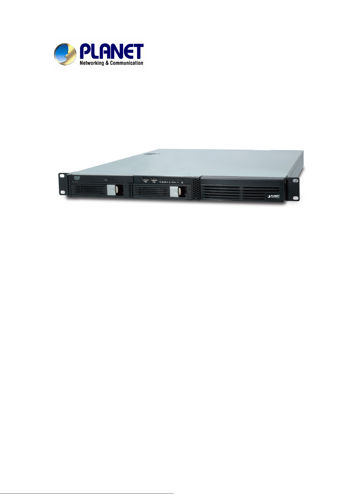
Designed for next generation communications networks by the voice and video over IP experts, the
PLANET Multipoint Control Unit is the smart solution that offers you an easy way to connect, conference,
and collaborate any way you want. In the video conferencing expertise, PLANET MCU multi-function
platform is the most flexible and total solution for deploying IP-centric voice, video and Surveillance
communications.
PLANET MCU-1400/1900 is a powerful IP multimedia conferencing device, delivering high quality voice
and video with IP surveillance capabilities, the platform is a leading solution for deploying real-time voice,
video and Surveillance services over IP. Stream your video conference over your intranet or the Internet.
The MCU operates with PLANET IP camera to offer viewing at multiple speeds to ensure that everyone
can easy video conferencing and watch the IP camera without difficulty.
1
An easy conferencing start with preset configurations of unified, voice, video, and Surveillance
conferencing, the MCU-1400 offers up to 4 video, 20 audio concurrent calls, and up to 50 user
registrations, the MCU-1900 offers up to 9 video , 60 audio concurrent calls, and up to 200 user
registrations, it's ideal for the small to medium-size enterprise and SOHO markets..
Page 6

MCU Features
Multi-Codec for H.263 / H.263p / MPEG-4 compression
Support Video / Voice Control service
Simultaneous Voice calls: 20(MCU-1400) / 60(MCU-1900) concurrent calls
Simultaneous Video calls: 4(MCU-1400) / 12(MCU-1400) concurrent calls
Support IP-Surveillance Hosting service
Call Detailed Record (CDR)
User Management via Web Browsers
Built-in SIP Proxy Server Following RFC-3261
Asterisk Compatible MCU
Recording MCU room’s Video/Voice to File
MCU-1400 Video MCU screen format: 1:1, 1:4
MCU-1900 Video MCU screen format: 1:1, 1:4, 1: 6, 1:7, 1:8, 1:9
Call Transfer / Forward / Hold / Call Parking
Package Content
The contents of your product should contain the following items:
Multipoint Control Unit
Quick Installation Guide
User’s Manual CD
Power Core
Rail x 2
L-shaped bracket x2
Physical Details
The following figure illustrates the front/rear panel of MCU.
6
Page 7
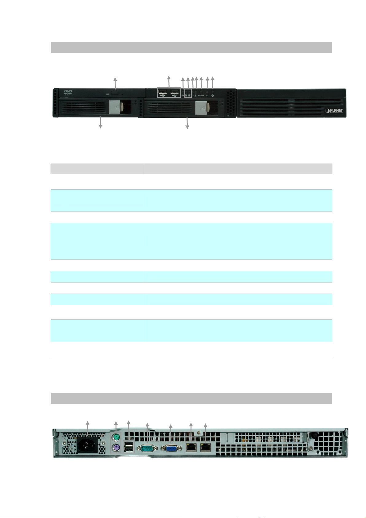
Front Panel Indicators
10
Item Description
1 DVD Rom
2 USB Port
3 Power LED
4 Network LED
5 System ID LED
1
2
7 9
6
5
4
3
8
11
Figure 1-1. Front Panel of MCU
Slim DVD-Rom device.
*This advanced feature will available in the future.
The USB port allows users to connect an external USB device to
the unit, such as a USB ThumbDrive© or a USB mouse.
*This advanced feature will available in the future.
It lights up when power source is connected.
1. The green LED is on when there is an active connection on the
LAN port.
2. This LED flashes when transmitting or receiving activities to or
from the system are detected.
Reserve for advanced system faculty.
6 System Alert LED
7 System ID button
8 System Reset button
9 Power button
System HDD Removable
10
Rack
11 HDD Removable Rack
Rear Panel Indicators
1
2
3
Reserve for advanced system faculty.
Reserve for advanced system faculty.
Press this button once to reboot the system.
Press this button once to shut down the system, and then once to
switch on.
The system HDD installed in this rack, and we don’t suggest
removing it for making sure the system could work properly.
This HDD rack leaves unused and it also useless to expand HDD.
*This advanced feature will available in the future.
Table1-1. Front Panel description of MCU
4
5
6
7
Figure 1-2. Rear Panel of MCU
7
Page 8

Item Description
1 Power Jack
PS/2 Keyboard/Mouse
2
Connector
3 USB Port
4 Serial Port
5 VGA Port
6 LAN Jack (Eth0)
7 LAN Jack (Eth1)
Connect the power supply cord shipped with the system. Use of
other power supply cords may cause overloading.
The PS/2 allow user to connect keyboard and mouse for operating
the system.
The USB port allows users to connect an external USB device to
the unit, such as a USB ThumbDrive© or a USB mouse.
*This advanced feature will available in the future.
The serial port for sending and receiving signals.
A VGA output connector is offered for connecting to a VGA
monitor.
These RJ-45 ports support auto negotiating Fast Ethernet
10/100/1000 Base-TX networks. That allows your system to be
connected to an Internet Access device, e.g. router, cable
modem, ADSL modem, through a CAT.5 twisted pair Ethernet
cable.
Table 1-2. Rear Panel description of MCU
8
Page 9
Chapter 2
Preparations & Installation
2
Physical Installation Requirement
This chapter illustrates basic installation of MCU
• Network cables. Use standard 10/100/1000Base-TX network (UTP) cables with RJ45
connectors.
• TCP/IP protocol must be installed on all PCs.
For Internet Access, an Internet Access account with an ISP, and either of a DSL or Cable modem (for
WAN port usage)
Administration Interface
PLANET MCU provides GUI (Web based, Graphical User Interface) for machine management and
administration.
Web configuration access
To start MCU web configuration, you must have the web browsers installed on computer for
management
•
Microsoft Internet Explorer 6.0.0 or higher with Java support
Default Eth0 interface IP address of MCU is 172.16.0.1. You may now open your web browser, and
insert 172.16.0.1 in the address bar of your web browser to logon MCU web configuration page.
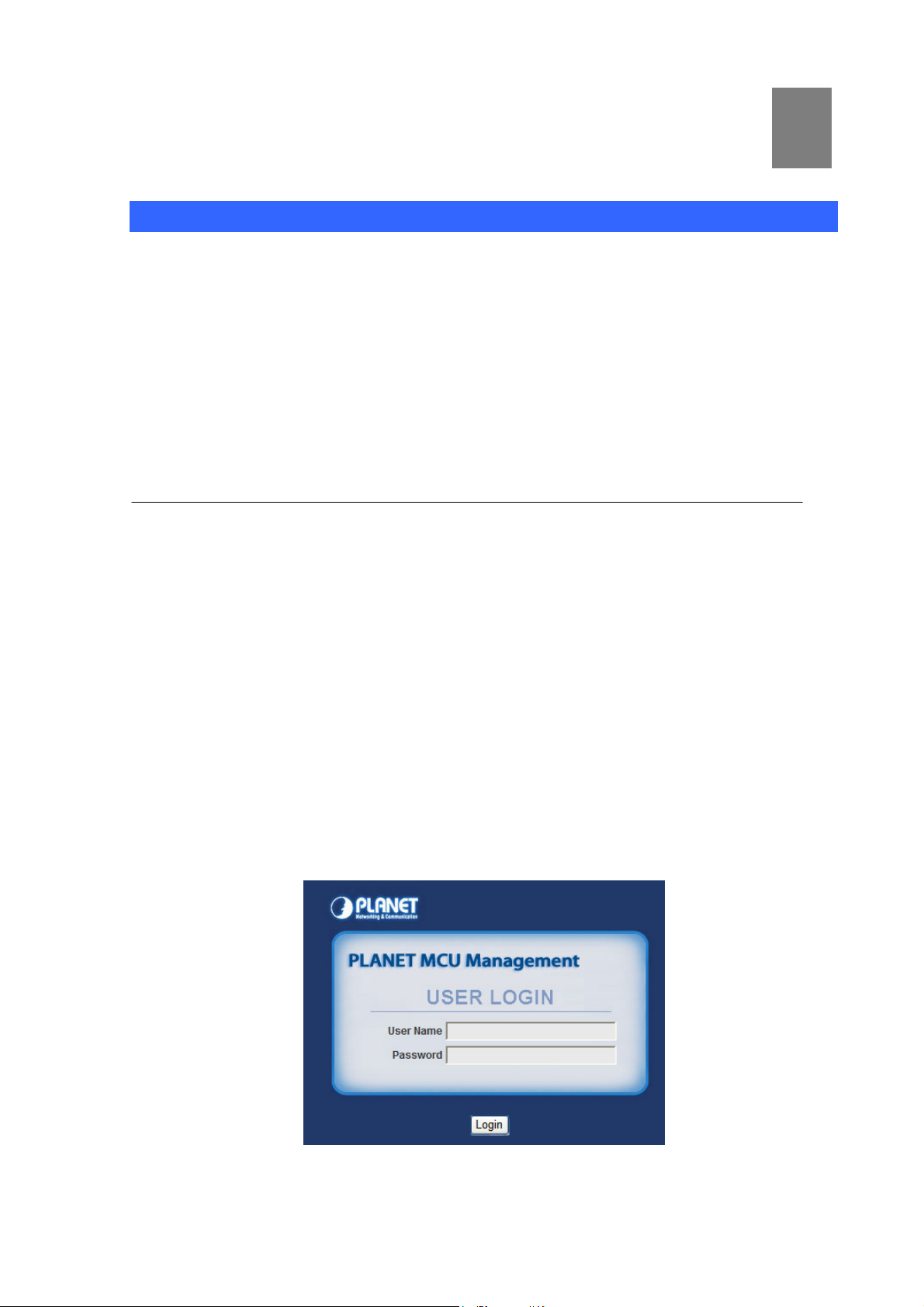
MCU will prompt for logon username/password, please enter: admin / 123 to continue machine
administration.
:
Figure 2-1. Input prompt
Page 10

In order to connect machine for administration, please
Í
Note
locate your PC in the same network segment (172.16.0.x) of
MCU. If you’re not familiar with TCP/IP, please refer to
related chapter on user’s manual CD or consult your network
administrator for proper network configurations.
10
Page 11

Chapter 3
System Configuration
Network Setup
The MCU has installed two NIC (Network Interface Card) in system; it allows you could setup the
related network parameters for each NIC, and DNS server in this page.
¾ Eth0/Eth1
The MCU just support the static IP mode. Please enter in the IP address, subnet mask, gateway
address address(es) provided to you by your ISP. Each IP address entered in the fields must be in the
appropriate IP form, which are four IP octets separated by a dot (x.x.x.x). The Router will not accept the
IP address if it is not in this format.
3
Figure 3-1. Network settings
¾ DNS
DNS stands for Domain Name System. Every Internet host must have a unique IP address; also they
may have a user-friendly, easy to remember name such as www.planet.com.tw
converts the user-friendly name into its equivalent IP address. The original DNS specifications require
that each domain name is served by at least 2 DNS servers for redundancy. When you run your DNS,
web, and mail servers all on the same MAChine - if this MAChine goes down, it doesn't really matter
that the backup DNS server still works.
The recommended practice is to configure the primary and secondary DNS servers on separate
MAChines, on separate Internet connections, and in separate geographic locations.
. The DNS server
Figure 3-2. DNS server settings
Page 12

Subscribers
This page allows the users to add /edit /delete extensions in the VoIP telephony network.
Figure 3-3. Subscriber’s settings
Alias
Account Number
Password
Video Codec
Audio Codec
Input User Name
Input Subscriber account (number)
Input Subscriber password
There are 3 kinds of video codec’s for selection by video phone
extension: H.263/H.263p/MPEG4. Please to check which video
codec supported by video phone, and to assign for each
extension.
The Audio Codec is used to compress the voice signal into data
packets. Each Codec has different bandwidth requirement.
There are 3 kinds of codec’s for selection by each extension:
G.711u/G.729/G.723.
To assign the incoming call redirect to voice mail automatically,
or assign the call forward function and fill in the forward number
at the late field.
There are four options to stand for voice mail or call forward:
M (Voice Mail): Redirecting the incoming call to voice mail if
Voice Mail /
Incoming Call
Forward
enable this option.
A (Always Forward): Redirecting the incoming call to the
specific number directly.
N (No Answer Forward): If no answer the incoming call after
specific time, it will be redirected to the specific number.
B (Busy Forward): If extension on call and there is incoming
call simultaneously, the incoming call will be redirected to the
specific number.
Table 3-1. Subscriber’s description
12
Page 13

SIP Trunk
SIP Trunk allows MCU registers to different SIP systems and ITSP Services.
You just need to fill the related account information in the fields. Maximum 20 registrations on SIP
Trunk.
Figure 3-4. SIP Trunk settings
Alias
Proxy : Port
Account
Password
Numbers
Audio Codec
To mark the trunk name.
Assigns the SIP Proxy Server’s IP address / Domain
name and Port number.
User name for authentication
User password for authentication
User number for authentication
Set allow voice codec
Table 3-2. SIP Trunk description
Dial Plan
When want to make VoIP calls through the above SIP or Gateway Trunk, the user can use the “Dial
Plan” function to simplify the dialing number.
Figure 3-5. Dial Plan settings
Prefix
Add
Drap
Trunk-selection
Prefix number is the leading digit of the call out dialing
number.
Add number is the digits that will be added to the
beginning of the dialed number.
Frap length is the number of digits that will be stripped
from beginning of the dialed number.
To choose the IP Phone, MCU or SIP Trunk.
Table 3-3. Dial Plan description
13
Page 14

IP Cam
The MCU has support the IP-Surveillance Hosting services, the MCU subscribers could see the IP
camera surveillance pictures via video phone or soft phone.
Figure 3-6. IP Cam setting
To assign an phone number for IP camera, so that the subscriber
Number
just need to dial the IP camera phone number to see the real time
surveillance pictures via video phone.
To fill in the IP camera IP address and the RTSP URL. For
example:
IP Address
Frame Size
FPS
Bitrate
VCS Settings
rtsp://192.168.0.20:554/mpeg4/1/media.amp?resolution=vga
You could refer to the Appendix B for Planet IP camera RTSP
URL, or contact with your provider for the camera RTSP URL.
To define the IP camera’s video size: CIF/QCIF
Defines the targeted frame rate for IP camera. For example, set
the frame rate to 15 fps, then the image will be updated for 15
frames per second. User can set the desired max frame rate
versus video quality under the limited bandwidth.
Defines Bitrate size, there are five types of bit rates:
64/128/256/384/512 Kbps. User can set the desired bit rate to
match the limitation of bandwidth.
Table 3-4. IP Cam description
MCU supports Video / Voice conferencing service, the MCU-1400 supports to 1 video and 3 voice
conference rooms. The MCU-1900 supports to 3 video and 9 voice conference rooms.
14
Page 15

Figure 3-7. VCS setting
Rome Num
Password
Composition
Size
BitRate
FPS
VCS Status
To assign the conference room number.
To assign the conference room password.
To assign the video layout types. If set as Free type, the conferee
could dial # button to change video layout.
To define the IP camera’s video size: CIF/QCIF
Defines Bitrate size, there are five types of bit rates:
64/128/256/384/512 Kbps. User can set the desired bit rate to match
the limitation of bandwidth.
Defines the targeted frame rate for IP camera. For example, set the
frame rate to 15 fps, then the image will be updated for 15 frames per
second. User can set the desired max frame rate versus video quality
under the limited bandwidth.
Table 3-5. VCS description
VCS Status allows administrator to monitor the conference room status. If there is conferee entry the
conference room, one of block will show the subscriber’s user name and number, and the people icon
will become green color:
15
Page 16

Figure 3-8. VCS Status
The Administrator could press the button to pause this conferee to
make speech, and press it again to revive the speechs.
The Administrator could press the button to kick this conferee out this
conference.
This icon on behalf of there isn’t conferee.
This icon on behalf of there is conferee.
Table 3-6. VCS status description
Channel Status
This page displays the information of Subscriber/SIP Trunk registration status. Besides show it on
Registrations Status, you also could discriminate different status by different background colors.
Figure 3-9. Channel Status
16
Page 17

Alias
The User name
Account/Number
Reg. IP Public /
Privacy
Reg. Status
Connecting numbers
The SIP Trunk account or Subscriber number
It will show what Public IP address was registered to
MCU. It also will show Privacy IP address if this device
put in Virtual network.
It will show if device registered to MCU successfully or
not.
If this subscriber is communicating with other object, it
will show object’s name.
Table 3-7. Channel Status description
Upgrade / Backup
You can upgrade the firmware of the device using this tool. Make sure that the firmware you want to use
is saved on the local hard drive of your computer. Click on Browse to search the local hard drive for the
firmware to be used for the update.
Beside the upgrade firmware function, you also could Import the configuration file, or to Export the
configuration file.
Figure 3-10. Upgrade / Backup settings
Password
You could change the Web Management Interface login Account and Password in this page.
17
Page 18

Figure 3-11. Password settings
Reboot
The system will been reboot after press the button.
Figure 3-12. Reboot settings
18
Page 19

Appendix A
Video Communication Samples
The chapter shows you the concept and command to help you configure your MCU System through
sample configuration. And provide several ways to make calls to desired destination in MCU. In this
section, we’ll lead you step by step to establish your first voice communication via web browsers
operations.
IP Phone register to MCU
Bring the power of visual communication to any meeting room, auditorium and training facility with the
MCU's professional video and audio technology.
Figure A-1. Video Conference scenario
Page 20

¾ Machine Configuration:
STEP 1:
Please login to MCU and browse to “Subscribers” configuration menu. To add four subscriber
accounts for conferees.
Figure A-2. Subscriber’s settings
STEP 2:
Please browse to “VCS Settings” configuration menu, and to setup the Room Number /
Password and related settings.
Figure A-3. VCS settings
STEP 3:
Please login in Video Phone (ICF-1600) and browse to “Basic Settings Æ SIP Configuration”
configuration menu to fill in the registration settings...
Figure A-4. SIP configuration settings
20
Page 21

STEP 4:
Please browse to “Advance Settings Æ SIP Settings” configuration menu to fill in the SIP Proxy
Server IP address.
Figure A-5. SIP settings
STEP 5:
Please browse to “Advance Settings Æ System Settings” configuration menu to setup the
Video codec and Audio Codec settings.
Figure A-6. System settings
STEP 6:
Please refer to the above descriptions (Step 3~5) and let other Video Phone (ICF-1600) register
to MCU.
¾ Test the Scenario:
1. All of Video Phone dial 999 and input the password (1234) to entry the conference room.
2. Each conferee will see everyone’s video pictures by 2x2 division layout and they could precede
the video conference.
21
Page 22

IP Phone register to MCU
By the MCU's powerful video streaming feature, it is convenient to achieve the surveillance network via
Video Phone.
Figure B-1. IP-Surveillance Hosting sample scenario
STEP 1:
Please refer to the first sample and let Video Phone register to MCU.
STEP 2:
Please put Speed Doom Internet Camera (ICA-H651) and Infrared Internet Camera (ICA-H312)
on the same network topology with MCU and Video Phone, and make sure they could reach to each
other via network connections properly.
STEP 3:
Please login to MCU and browse to “IP Cam” configuration menu. According to the IP camera
RTSP URL format to fill in the related fields.
Page 23

Figure B-2. IP Cam settings
¾ Test the Scenario:
1. The Video Phone dials 310 to view the surveillance pictures of ICA-H312.
2. The Video Phone dials 651 to view the surveillance pictures of ICA-H651.
23
Page 24

Appendix B
PLANET IP Camera RTSP URL References
The following table lists the greater part of Planet IP camera RTSP streaming links sample for
performing the MCU’s IP-Surveillance Hosting function.
Group 1 / Camera Model
Group 1 Streaming link
Group 2 / Camera Model
Group 2 Streaming link
Group 3 / Camera Model
Group 3 Streaming link
Group 4 / Camera Model
Group 4 Streaming link
ICA-108/108W, ICA-120, ICA-HM130/135, ICA-230/M230/HM230,
ICA-312/H312, ICA-501, ICA-525, ICA-530, ICA-651/H651, ICA-601,
ICA-310, ICA-350/HM350, IVS-110
rtsp://<IP address>:554/mpeg4/1/media.amp?resolution=vga
ICA-750, ICA-151, ICA-150W, ICA-550W
rtsp://<IP address>:554/img/media.sav
ICA-M220/M220W, ICA-107/107W
rtsp://<IP address>:554/ipcam.sdp
ICA-510, ICA-700
rtsp://<IP address>:8554/video.3gp
Page 25

Appendix C
e
FAQ
Q1: What is the default IP address to login the MCU?
A:
• By default, the Eth0 interface IP address of MCU is 172.16.0.1, and the Eth1 interface
IP address of MCU is 192.168.0.1
Q2 : What is the default Username and Password to login the MCU?
A:
• By default, the login username is admin, password is 123
Q3 : Why I can not use the Voice / Video Conference function?
A:
• Please to create a conference room number and related settings at first via web
management interface.
• Then the devices could dial the conference room number for establishing the
conference function.
Q4 : When I performing the Video Conference, how can I change the video layout?
A:
• Please press the # key to change the division pictures for different video layouts.
Q5 : Why I can not perform the IP camera host function?
A:
• Please make sure the IP camera has support RTSP streaming feature, and to check th
streaming format for it.
• Then please setup the IP address plus streaming links and related settings via web
management. So that you could dial the IP camera number to view the surveillance
pictures.
Page 26

Appendix D
MCU Series Specifications
Product Multipoint Control unit
Model MCU-1400 MCU-1900
Hardware
LAN 2 RJ-45 (10/100/1000Base-TX, Auto-Sensing/Switching)
Standards and Protocol
Call control SIP 2.0 (RFC3261) , SDP (RFC 2327), Symmetric RTP
SIP Registration 50 200
Voice Concurrent Calls 20 60
Video Concurrent Calls 4 12
Voice Room Number 3 9
Video Room Number 1 3
Voice CODEC Support G.711u, G.723, G.729
Video MPEG-4, H.263, H.263p
DTMF detection and generation
Voice Processing
In-Band and Out-of-Band (RFC 2833), (SIP INFO)
Supports password authentication using MD5 digest
Voicemail Support (VM)
PBX Features
Call Features
Call Detailed Record (CDR)
User Management via Web Browsers
Web Firmware Upgrade
Backup and Restore Configuration file
Displays Registered User’s Status: Unregistered / Registered / Caller /
Callee
Caller ID
Call Hold
Call Transfer
Call Forward (Always, Busy, No Answer)
Call Pickup
Call Parking
Music/Video on Hold
Three-way voice conference with feature phones (VIP-254T series,
VIP-155PT / 255PT / 351PT / ICF-1600 and ATA series: VIP-156 /
157, ATA-150 / 150S)
MCU Room Configuration
MCU Room Features
Video MCU Display Division 1, 4 1, 4, 6, 7, 8, 9
Internet Sharing
Protocol TCP/IP, UDP/RTP/RTCP, HTTP, ICMP, ARP, NAT, DHCP, DNS
Connection Type Static IP
Management HTTP Web Browser
MCU status display on Web Browser
Mute / Kick function
MCU Voice/Video Recording
Page 27

System: 1, PWR
LED Indications
LAN: 2, LNK/ACT
System ID: 1
System Fault: 1
Hardware Specification
CPU Processor Quad-Core Intel Xeon 2.0GHz
RAM 1GB
Built-in Storage Device 1 x DVD Rom, 1 x 160GB HDD
Ethernet Interface 2 x RJ-45 10/100/1000Base-TX
Input/Output Interface 2 x PS2 Mouse/Keyboard, 2 x USB 2.0, 1 x Serial, 1 x VGA
Form Factor 1U, 19” Rack Mountable
EMC/EMI CE, FCC Class B
Environment
Dimension (W x D x H) 428 x 442 x 44.4 mm
Operating Temperature 0~40 degree C, 0~90% humidity
Power Source AC 100~240V, 50-60Hz
Power Requirement 300W
Safety UL, CB, BSMI
EMC/EMI CE Class A, FCC Class A, BSMI Class B
27
 Loading...