

Page 1
Page 2

User’s Manual of LRP-822CS/LRP-1622CS
Trademarks
Copyright © PLANET Technology Corp. 2015.
Contents are subject to revision without prior notice.
PLANET is a registered trademark of PLANET Technology Corp. All other trademarks belong to their respective owners.
Disclaimer
PLANET Technology does not warrant that the hardware will work properly in all environments and applications, and makes no
warranty and representation, either implied or expressed, with respect to the quality, performance, merchantability, or fitness for
a particular purpose. PLANET has made every effort to ensure that this User's Manual is accurate; PLANET disclaims liability
for any inaccuracies or omissions that may have occurred.
Information in this User's Manual is subject to change without notice and does not represent a commitment on the part of
PLANET. PLANET assumes no responsibility for any inaccuracies that may be contained in this User's Manual. PLANET makes
no commitment to update or keep current the information in this User's Manual, and reserves the right to make improvements to
this User's Manual and/or to the products described in this User's Manual, at any time without notice.
If you find information in this manual that is incorrect, misleading, or incomplete, we would appreciate your comments and
suggestions.
FCC Warning
This equipment has been tested and found to comply with the limits for a Class A digital device, pursuant to Part 15 of the FCC
Rules. These limits are designed to provide reasonable protection against harmful interference when the equipment is operated
in a commercial environment. This equipment generates, uses, and can radiate radio frequency energy and, if not installed and
used in accordance with the Instruction manual, may cause harmful interference to radio communications. Operation of this
equipment in a residential area is likely to cause harmful interference in which case the user will be required to correct the
interference at his own expense.
CE Mark Warning
This is a Class A product. In a domestic environment, this product may cause radio interference, in which case the user may be
required to take adequate measures.
Energy Saving Note of the Device
This power required device does not support Standby mode operation. For energy saving, please remove the power cable to
disconnect the device from the power circuit. In view of saving the energy and reducing the unnecessary power consumption, it
is strongly suggested to remove the power connection for the device if this device is not intended to be active.
WEEE Warning
To avoid the potential effects on the environment and human health as a result of the presence of hazardous
substances in electrical and electronic equipment, end users of electrical and electronic equipment should
understand the meaning of the crossed-out wheeled bin symbol. Do not dispose of WEEE as unsorted
municipal waste and have to collect such WEEE separately.
Revision
PLANET Multi-port Coax + 2-port 10/100/1000T + 2-port 100/1000X SFP Long Reach PoE over Coaxial Switch User's Manual
For Model: LRP-822CS/LRP-1622CS
Revision: 1.1 (Jul. 2015)
Part No: EM-LRP-822CS_LRP-1622CS_v1.1
2
Page 3

User’s Manual of LRP-822CS/LRP-1622CS
TABLE OF CONTENTS
1. INTRODUCTION..................................................................................................................10
1.1 Packet Contents.........................................................................................................................................10
1.2 Product Description...................................................................................................................................11
1.3 How to Use This Manual............................................................................................................................16
1.4 Product Features........................................................................................................................................16
1.5 Product Specifications ..............................................................................................................................19
2. INSTALLATION ................................................................................................................... 23
2.1 Hardware Description................................................................................................................................23
2.1.1 Switch Front Panel ..............................................................................................................................................23
2.1.2 LED Indications ...................................................................................................................................................25
2.1.3 Switch Rear Panel ...............................................................................................................................................27
2.2 Installing the Switch...................................................................................................................................28
2.2.1 Desktop Installation .............................................................................................................................................28
2.2.2 Rack Mounting.....................................................................................................................................................29
2.2.3 Installing the SFP transceiver ..............................................................................................................................30
2.2.4 Installing the Long Reach PoE Communication...................................................................................................33
3. SWITCH MANAGEMENT.................................................................................................... 37
3.1 Requirements..............................................................................................................................................37
3.2 Management Access Overvi ew.................................................................................................................38
3.3 Administration Console.............................................................................................................................39
3.4 Web Management.......................................................................................................................................40
3.5 SNMP-based Network Management.........................................................................................................41
3.6 PLANET Smart Discovery Utility ..............................................................................................................41
4. WEB CONFIGURATION...................................................................................................... 43
4.1 Main Web Page...........................................................................................................................................46
4.1.1 Save Button .........................................................................................................................................................47
4.1.2 Configuration Manager ........................................................................................................................................48
4.1.2.1 Saving Configuration .................................................................................................................................49
3
Page 4

User’s Manual of LRP-822CS/LRP-1622CS
4.2 System.........................................................................................................................................................50
4.2.1 System Information..............................................................................................................................................50
4.2.2 IP Configurations .................................................................................................................................................51
4.2.3 IPv6 Configuration ...............................................................................................................................................53
4.2.4 User Configuration...............................................................................................................................................55
4.2.5 Time Settings.......................................................................................................................................................56
4.2.5.1 System Time..............................................................................................................................................56
4.2.5.2 SNTP Server Settings ...............................................................................................................................59
4.2.6 Log Management.................................................................................................................................................60
4.2.6.1 Local Log...................................................................................................................................................60
4.2.6.2 Local Log...................................................................................................................................................61
4.2.6.3 Remote Syslog ..........................................................................................................................................63
4.2.6.4 Log Message .............................................................................................................................................64
4.2.7 SNMP Management ............................................................................................................................................67
4.2.7.1 SNMP Overview ........................................................................................................................................67
4.2.7.2 SNMP System Information ........................................................................................................................68
4.2.7.3 SNMP View ...............................................................................................................................................69
4.2.7.4 SNMP Access Group.................................................................................................................................71
4.2.7.5 SNMP Community .....................................................................................................................................72
4.2.7.6 SNMP User................................................................................................................................................74
4.2.7.7 SNMPv1, 2 Notification Recipients ............................................................................................................ 75
4.2.7.9 SNMPv3 Notification Recipients ................................................................................................................ 77
4.2.7.10 SNMP Engine ID .....................................................................................................................................78
4.2.7.11 SNMP Remote Engine ID ........................................................................................................................79
4.3 Port Management.......................................................................................................................................80
4.3.1 Port Configuration................................................................................................................................................80
4.3.2 LRP Port Configuration........................................................................................................................................82
4.3.3 Port Counters ......................................................................................................................................................84
4.3.4 Bandwidth Utilization ...........................................................................................................................................89
4.3.5 Port Mirroring.......................................................................................................................................................90
4.3.6 Jumbo Frame ......................................................................................................................................................92
4.3.7 Port Error Disabled Configuration ........................................................................................................................93
4.3.8 Port Error Disabled ..............................................................................................................................................95
4.3.9 Protected Ports....................................................................................................................................................95
4.3.10 EEE ...................................................................................................................................................................98
4.3.11 SFP Module Information ....................................................................................................................................99
4.3.11.1 SFP Module Status..................................................................................................................................99
4.3.11.1 SFP Module Detail Status......................................................................................................................101
4
Page 5

User’s Manual of LRP-822CS/LRP-1622CS
4.4 Link Aggregation......................................................................................................................................102
4.4.1 LAG Setting .......................................................................................................................................................104
4.4.2 LAG Managment ...............................................................................................................................................105
4.4.3 LAG Port Setting................................................................................................................................................106
4.4.4 LACP Setting .....................................................................................................................................................108
4.4.5 LACP Port Setting..............................................................................................................................................109
4.4.6 LAG Status ........................................................................................................................................................ 110
4.5 VLAN..........................................................................................................................................................113
4.5.1 VLAN Overview ................................................................................................................................................. 113
4.5.2 IEEE 802.1Q VLAN ........................................................................................................................................... 114
4.5.3 Management VLAN ........................................................................................................................................... 117
4.5.4 Create VLAN .....................................................................................................................................................118
4.5.5 Interface Settings............................................................................................................................................... 119
4.5.6 Port to VLAN......................................................................................................................................................124
4.5.7 Port VLAN Membership .....................................................................................................................................125
4.5.8 Protocol VLAN Group Setting ............................................................................................................................ 126
4.5.9 Protocol VLAN Port Setting ...............................................................................................................................127
4.5.10 GVRP Setting ..................................................................................................................................................129
4.5.11 GVRP Port Setting...........................................................................................................................................131
4.5.12 GVRP VLAN ....................................................................................................................................................133
4.5.13 GVRP Statistics ...............................................................................................................................................133
4.5.14 VLAN Setting Example: ...................................................................................................................................135
4.5.14.1 Two Separate 802.1Q VLANs................................................................................................................135
4.5.14.2 VLAN Trunking between Two 802.1Q Aware Switches .........................................................................138
4.6 Spanning Tree Protocol...........................................................................................................................141
4.6.1 Theory ...............................................................................................................................................................141
4.6.2 STP Global Settings ..........................................................................................................................................147
4.6.3 STP Port Setting................................................................................................................................................149
4.6.4 CIST Instance Setting........................................................................................................................................152
4.6.5 CIST Port Setting...............................................................................................................................................154
4.6.6 MST Instance Configuration ..............................................................................................................................156
4.6.7 MST Port Setting ...............................................................................................................................................159
4.6.8 STP Statistics ....................................................................................................................................................161
4.7 Multicast....................................................................................................................................................162
4.7.1 Properties ..........................................................................................................................................................162
4.7.2 IGMP Snooping .................................................................................................................................................164
4.7.2.1 IGMP Setting ...........................................................................................................................................168
4.7.2.2 IGMP Querier Setting ..............................................................................................................................170
5
Page 6

User’s Manual of LRP-822CS/LRP-1622CS
4.7.2.3 IGMP Static Group...................................................................................................................................171
4.7.2.4 IGMP Group Table...................................................................................................................................172
4.7.2.5 IGMP Router Setting ...............................................................................................................................173
4.7.2.6 IGMP Router Table..................................................................................................................................174
4.7.2.7 IGMP Forward All ....................................................................................................................................175
4.7.3 IGMP Snooping Statics......................................................................................................................................176
4.7.4 MLD Snooping...................................................................................................................................................178
4.7.4.1 MLD Setting.............................................................................................................................................178
4.7.4.2 MLD Static Group ....................................................................................................................................180
4.7.4.3 MLD Group Table ....................................................................................................................................181
4.7.4.4 MLD Router Setting .................................................................................................................................181
4.7.4.5 MLD Router Table....................................................................................................................................183
4.7.4.6 MLD Forward All......................................................................................................................................184
4.7.5 MLD Snooping Statics .......................................................................................................................................185
4.7.6 Multicast Throttling Setting ................................................................................................................................187
4.7.7 Multicast Filter ...................................................................................................................................................188
4.7.7.1 Multicast Profile Setting ........................................................................................................................... 189
4.7.7.2 IGMP Filter Setting ..................................................................................................................................190
4.7.7.3 MLD Filter Setting....................................................................................................................................191
4.8 Quality of Service.....................................................................................................................................193
4.8.1 Understand QoS................................................................................................................................................193
4.8.2 General..............................................................................................................................................................194
4.8.2.1 QoS Properties ........................................................................................................................................194
4.8.2.2 QoS Port Settings....................................................................................................................................195
4.8.2.3 Queue Settings........................................................................................................................................196
4.8.2.4 CoS Mapping...........................................................................................................................................197
4.8.2.5 DSCP Mapping........................................................................................................................................199
4.8.2.6 IP Precedence Mapping ..........................................................................................................................201
4.8.3 QoS Basic Mode................................................................................................................................................202
4.8.3.1 Global Settings ........................................................................................................................................202
4.8.3.2 Port Settings............................................................................................................................................203
4.8.4 Rate Limit ..........................................................................................................................................................204
4.8.4.1 Ingress Bandwidth Control ......................................................................................................................204
4.8.4.2 Egress Bandwidth Control .......................................................................................................................206
4.8.4.3 Egress Queue .........................................................................................................................................207
4.8.5 Voice VLAN .......................................................................................................................................................209
4.5.8.1 Introduction to Voice VLAN......................................................................................................................209
4.8.5.2 Properties ................................................................................................................................................209
4.8.5.3 Telephony OUI MAC Setting.................................................................................................................... 211
6
Page 7

User’s Manual of LRP-822CS/LRP-1622CS
4.8.5.4 Telephony OUI Port Setting.....................................................................................................................213
4.9 Security .....................................................................................................................................................215
4.9.1 802.1X ...............................................................................................................................................................215
4.9.1.1 Understanding IEEE 802.1X Port-based Authentication..........................................................................216
4.9.1.2 802.1X Setting .........................................................................................................................................219
4.9.1.3 802.1X Port Setting .................................................................................................................................220
4.9.1.4 Guest VLAN Setting ................................................................................................................................222
4.9.1.5 Authenticated Host ..................................................................................................................................225
4.9.2 RADIUS Server .................................................................................................................................................225
4.9.3 TACACS+ Server...............................................................................................................................................228
4.9.4 AAA ...................................................................................................................................................................231
4.9.4.1 Login List .................................................................................................................................................232
4.9.4.2 Enable List...............................................................................................................................................233
4.9.5 Access ...............................................................................................................................................................234
4.9.5.1 Telnet.......................................................................................................................................................234
4.9.5.2 SSH .........................................................................................................................................................235
4.9.5.3 HTTP .......................................................................................................................................................237
4.9.5.4 HTTPs .....................................................................................................................................................239
4.9.6 Management Access Method ............................................................................................................................240
4.9.6.1 Profile Rules ............................................................................................................................................240
4.9.6.2 Access Rules ...........................................................................................................................................241
4.9.7 DHCP Snooping ................................................................................................................................................243
4.9.7.1 DHCP Snooping Overview ......................................................................................................................243
4.9.7.2 Global Setting ..........................................................................................................................................244
4.9.7.3 VLAN Setting...........................................................................................................................................245
4.9.7.4 Port Setting..............................................................................................................................................247
4.9.7.5 Statistics ..................................................................................................................................................248
4.9.7.6 Database Agent.......................................................................................................................................249
4.9.7.7 Rate Limit ................................................................................................................................................251
4.9.7.8 Option 82 Global Setting .........................................................................................................................253
4.9.7.9 Option 82 Port Setting .............................................................................................................................254
4.9.7.10 Option 82 Circuit-ID Setting ...................................................................................................................256
4.9.8 Dynamic ARP Inspection ...................................................................................................................................257
4.9.8.1 Global Setting ..........................................................................................................................................257
4.9.8.2 VLAN Setting...........................................................................................................................................258
4.9.8.3 Port Setting..............................................................................................................................................259
4.9.8.4 Statistics ..................................................................................................................................................261
4.9.8.5 Rate Limit ................................................................................................................................................262
4.9.9 IP Source Guard................................................................................................................................................263
7
Page 8

User’s Manual of LRP-822CS/LRP-1622CS
4.9.9.1 Port Settings............................................................................................................................................264
4.9.9.2 Binding Table...........................................................................................................................................265
4.9.10 Port Security ....................................................................................................................................................267
4.9.11 DoS..................................................................................................................................................................269
4.9.11.1 Global DoS Setting ................................................................................................................................269
4.9.11.2 DoS Port Setting ....................................................................................................................................272
4.9.12 Storm Control...................................................................................................................................................274
4.9.12.1 Global Setting ........................................................................................................................................274
4.9.12.2 Port Setting............................................................................................................................................275
4.10 ACL ..........................................................................................................................................................277
4.10.1 MAC-based ACL..............................................................................................................................................277
4.10.2 MAC-based ACE .............................................................................................................................................278
4.10.3 IPv4-based ACL...............................................................................................................................................281
4.10.4 IPv4-based ACE ..............................................................................................................................................281
4.10.5 IPv6-based ACL...............................................................................................................................................287
4.10.6 IPv6-based ACE ..............................................................................................................................................287
4.10.7 ACL Binding .....................................................................................................................................................293
4.11 MAC Address Table................................................................................................................................294
4.11.1 Static MAC Setting...........................................................................................................................................294
4.11.2 MAC Filtering ...................................................................................................................................................295
4.11.3 Dynamic Address Setting.................................................................................................................................296
4.11.4 Dynamically Learned .......................................................................................................................................297
4.12 LLDP........................................................................................................................................................299
4.12.1 Link Layer Discovery Protocol .........................................................................................................................299
4.12.2 LLDP Global Setting ........................................................................................................................................299
4.12.3 LLDP Port Setting............................................................................................................................................302
4.12.4 LLDP Local Device ..........................................................................................................................................305
4.12.5 LLDP Remote Device ......................................................................................................................................306
4.12.6 MED Network Policy ........................................................................................................................................308
4.12.7 MED Port Setting............................................................................................................................................. 311
4.12.8 LLDP Overloading ...........................................................................................................................................314
4.12.9 LLDP Statistics.................................................................................................................................................315
4.13 Diagnostics.............................................................................................................................................317
4.13.1 Cable Diagnostics............................................................................................................................................317
4.13.2 Ping .................................................................................................................................................................319
4.13.3 Ping Test..........................................................................................................................................................319
4.13.4 IPv6 Ping Test..................................................................................................................................................320
8
Page 9

User’s Manual of LRP-822CS/LRP-1622CS
4.14 RMON.......................................................................................................................................................321
4.14.1 RMON Statistics ..............................................................................................................................................321
4.14.2 RMON Event ...................................................................................................................................................323
4.14.3 RMON Event Log ............................................................................................................................................324
4.14.4 RMON Alarm ...................................................................................................................................................325
4.14.5 RMON History .................................................................................................................................................328
4.14.6 RMON History Log ..........................................................................................................................................329
4.15 Power over Ethernet ..............................................................................................................................330
4.15.1 Long Reach Power over Ethernet Powered Device.........................................................................................331
4.15.2 System Configuration ......................................................................................................................................332
4.15.3 Power over Ethernet Configuration.................................................................................................................. 332
4.15.4 PoE Schedule..................................................................................................................................................335
4.15.5 PoE Alive Check Configuration........................................................................................................................ 338
4.16 Maintenance............................................................................................................................................340
4.16.1 Factory Default ................................................................................................................................................340
4.16.2 Reboot Switch .................................................................................................................................................341
4.16.3 Backup Manager .............................................................................................................................................341
4.16.4 Upgrade Manager............................................................................................................................................342
4.16.5 Dual Image ......................................................................................................................................................343
5. SWITCH OPERATION....................................................................................................... 344
5.1 Address Table...........................................................................................................................................344
5.2 Learning ....................................................................................................................................................344
5.3 Forwarding & Filtering.............................................................................................................................344
5.4 Store-and-Forward...................................................................................................................................344
5.5 Auto-Negotiation ......................................................................................................................................345
6. TROUBLESHOOTING....................................................................................................... 346
APPENDIX A .........................................................................................................................348
A.1 Switch's RJ45 Pin Assignments.............................................................................................................348
A.2 10/100Mbps, 10/100BASE-TX..................................................................................................................348
9
Page 10

User’s Manual of LRP-822CS/LRP-1622CS
1. INTRODUCTION
Thank you for purchasing PLANET LRP Managed Switch series, which comes with multiple Long Reach PoE female BNC,
Gigabit Ethernet copper and SFP fiber optic connectibility, and robust layer 2 and layer 4 features. The description of this model
is shown below:
LRP-822CS
8-port Coax + 2-port 10/100/1000T + 2-port 100/1000X SFP Long Reach PoE over Coaxial Managed Switch
LRP-1622CS
“LRP Managed Switch” is used as an alternative name in this user’s manual.
16-port Coax + 2-port 10/100/1000T + 2-port 100/1000X SFP Long Reach PoE over Coaxial Managed Switch
1.1 Packet Contents
Open the box of the LRP Managed Switch and carefully unpack it. The box should contain the following items:
The LRP Managed Switch x 1
Quick Installation Guide x 1
Rubber Feet x 4
Power Cord x 1
RS232 to RJ45 Console Cable x 1
SFP Dust Cap x 2
BNC Female Dust Cap x 8 (LRP-822CS)
BNC Female Dust Cap x 16 (LRP-1622CS)
Warning Sticker x 8 (LRP-822CS)
Warning Sticker x 16 (LRP-1622CS)
Rack-mount Accessory Kit x 1
If any item is found missing or damaged, please contact your local reseller for replacement.
10
Page 11
User’s Manual of LRP-822CS/LRP-1622CS
1.2 Product Description
PLANET Long Reach PoE Solu tion enables all enterprises and network service providers to set up an IP infrastructure in a
remote location where 802.3af/at PoE compliant powered devices can receive both data and power via PLANET switches, and
PLANET LRP extenders and injectors over a long distance but not limited to the normal 100 meters.
Intelligent Long Reach PoE Switch on Coaxial-based Network
PLANET LRP Managed Switch series, a brand-new Multi-channel Long Reach PoE Switch, features an extended Ethernet and
PoE networking of up to 1,000 meters over the existing coaxial cables going to multiple PoE IP cameras. It provides IPv6 / IPv4
dual stack management and built-in L2/L4 Gigabit Switching engine along with multi-BNC ports with Long Reach PoE Injector
function, 2 Gigabit copper ports and 2 extra 100/1000BASE-X SFP fiber slots. As an advanced PoE switch, the PLANET
LRP Managed Switch features intelligent PoE functions to improve the availability of critical applications. It provides a quick,
safe and cost-effective PoE network solution to upgrading the existing coaxial cable infrastructure from the analog system to the
HD IP surveillance system.
Multi-channel Long Reach Power over Ethernet
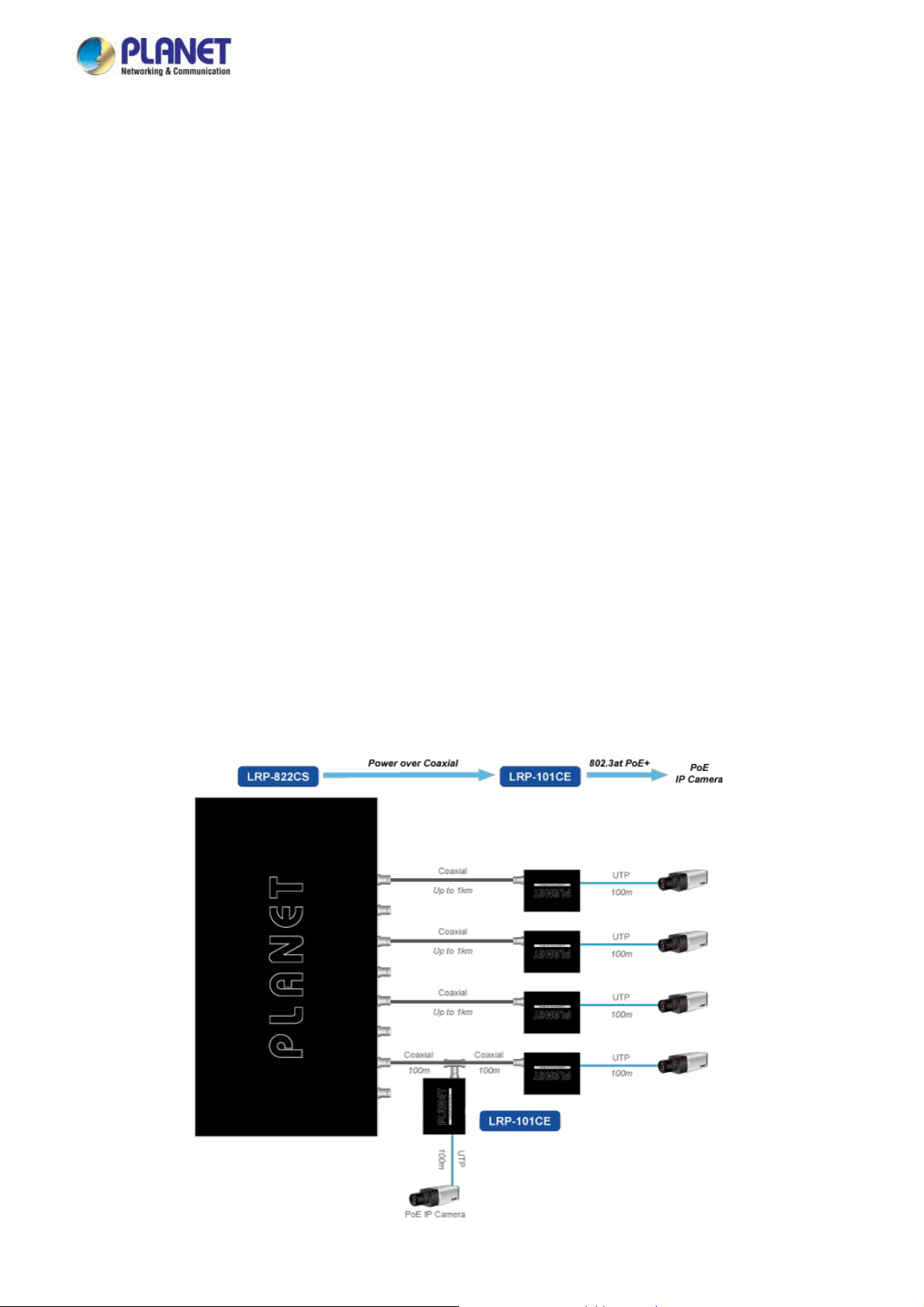
To support the enterprises in easily building a multi-channel and centrally-controlled Long Reach PoE system, the LRP-822CS
works with the Long Reach PoE Extenders, LRP-101CE, via its BNC ports being the Long Reach PoE injectors for all
connected LRP Extenders. Each of the BNC port features long range data and power transmission for distance up to 1,000m
(3,280ft) over coaxial cable to the LRP Extender, and another 100m over Ethernet cable to remote PoE IP camera, PoE
wireless AP or access control systems complied with 802.3af/at PoE.
11
Page 12
User’s Manual of LRP-822CS/LRP-1622CS
Centraliz
PLANET LRP Managed Switch eliminates the need for an additional remote site power while allowing a single power source to
provide power to both LRP extenders and the PoE powered devices at long range. The Long Reach PoE capabilities provided
help to reduce installation time and deployment costs for network devices as a result of freeing from restrictions of power outlet
locations.
ed Power Management
Daisy-chaining Multiple Nodes
PLANET Long Reach PoE solution can easily build a power system for centrally-controlled IP cameras in a high availability
network infrastructure. It gives users the flexibility to expand small area network with BNC T-connector for sharing four nodes
per port when needed.
Built-in Unique PoE Functions for Powered Devices Management
As a managed PoE switch for surveillance, wireless and VoIP networks, the PLANET LRP Managed Switch particularly features
the following special PoE Management functions to accomplish a highly-efficient Long Reach network:
PD Alive Check
Scheduled Power Recycling
PoE Schedule
PoE Usage Monitoring
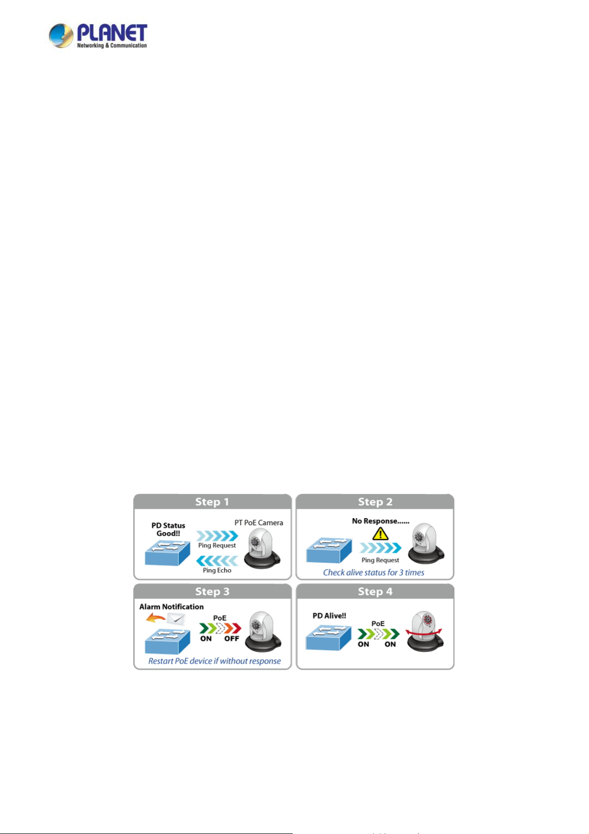
Intelligent Powered Device Alive Check
The PLANET LRP Managed Switch can be configured to monitor connected PD (Powered Device) status in real time via ping
action. Once the PD stops working and responding, the PLANET LRP Managed Switch will resume the PoE port power and
bring the PD back to work. It will greatly enhance the network reliability through the PoE port resetting the PD’s power source
and reducing administrator management burden.
12
Page 13
User’s Manual of LRP-822CS/LRP-1622CS
Scheduled P
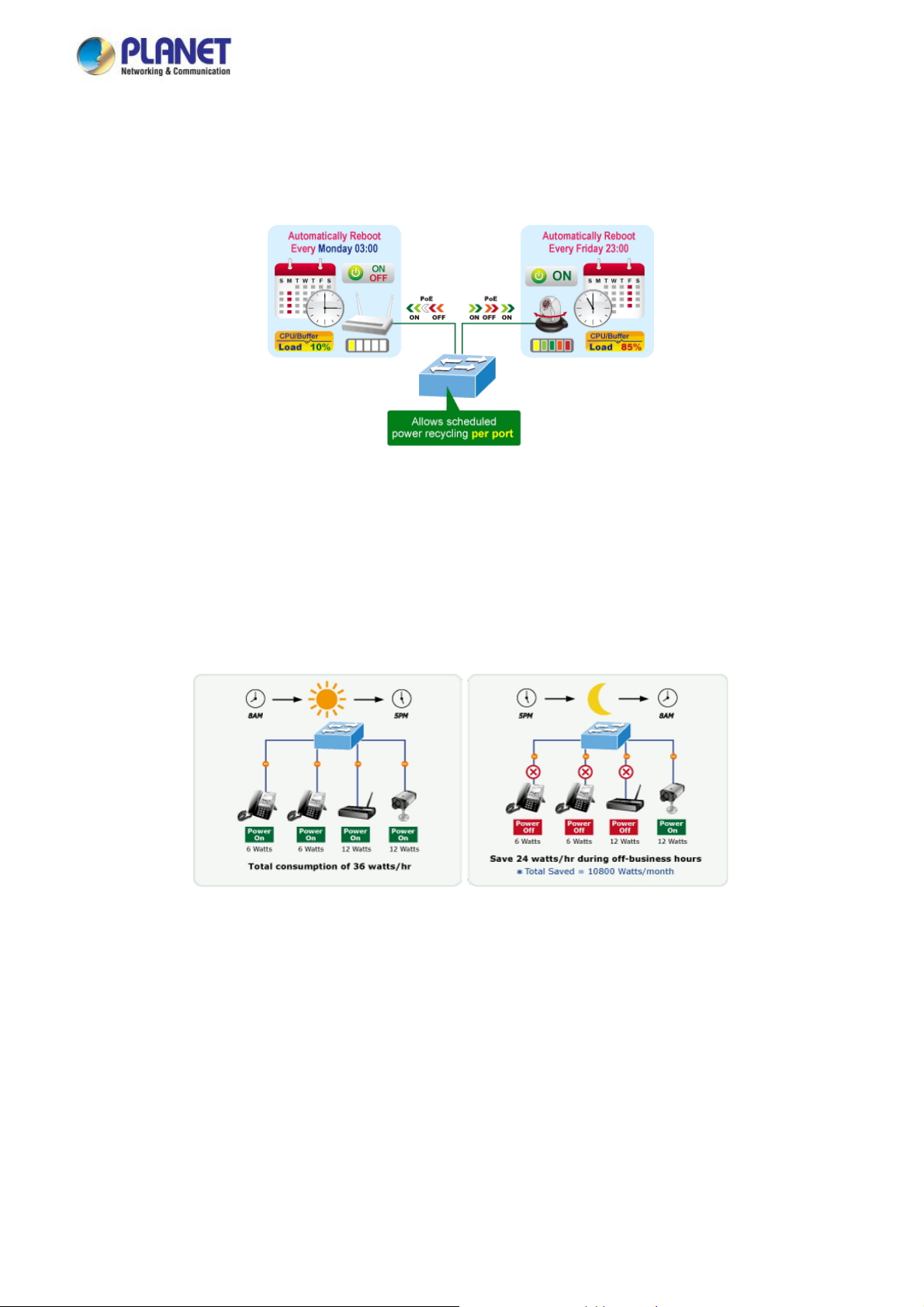
PLANET LRP Managed Switch allows each of the connected PoE IP cameras or PoE wireless access points via the
LRP-101CE to reboot at a specific time each week. Therefore, it will reduce the chance of IP camera or wireless AP crash
resulting from buffer overflow.
ower Recycling
PoE Schedule for Energy Saving
Under the trend of energy saving worldwide and contributing to environmental protection, the PLANET LRP Managed Switch
can effectively control the power supply besides its capability of giving high watts power. The “PoE schedule” function helps
you to enable or disable PoE power feeding for each PoE port during specified time intervals and it is a powerful function to help
SMBs or enterprises save power and money. It also increases security by powering off PDs that should not be in use during
non-business hours.
PoE Usage Monitoring
Via the power usage chart in the web management interface, PLANET LRP Managed Switch enables the administrator to
monitor the status of the power usage of the connected PDs in real time. Thus, it greatly enhances the management efficiency
of the facilities.
PoE Over-temperature Protection System
The over-temperature protection of PLANET LRP Managed Switch offers a safe and stable PoE operation by limiting the
output power in order to avoid destructive breakdown due to unexpected overheating.
13
Page 14
User’s Manual of LRP-822CS/LRP-1622CS
Environm
PLANET LRP Managed Switch features a 19-inch metal housing, a low noise design and an effective ventilation system. It
supports the smart fan technology to automatically control the speed of the built-in fan to reduce noise and maintain the
temperature of the PoE switch for optimal power output capability. PLANET LRP Managed Switch is able to operate reliably,
stably and quietly in any environment without affecting its performance.
ent-friendly, Smart Fan Design for Silent Operation
IPv6 / IPv4 Dual St ack
Supporting both IPv6 and IPv4 protocols, PLANET LRP Managed Switch enables SMBs to step in the IPv6 era with the lowest
investment as its network facilities need not be replaced or overhauled if the IPv6 FTTx edge network is set up.
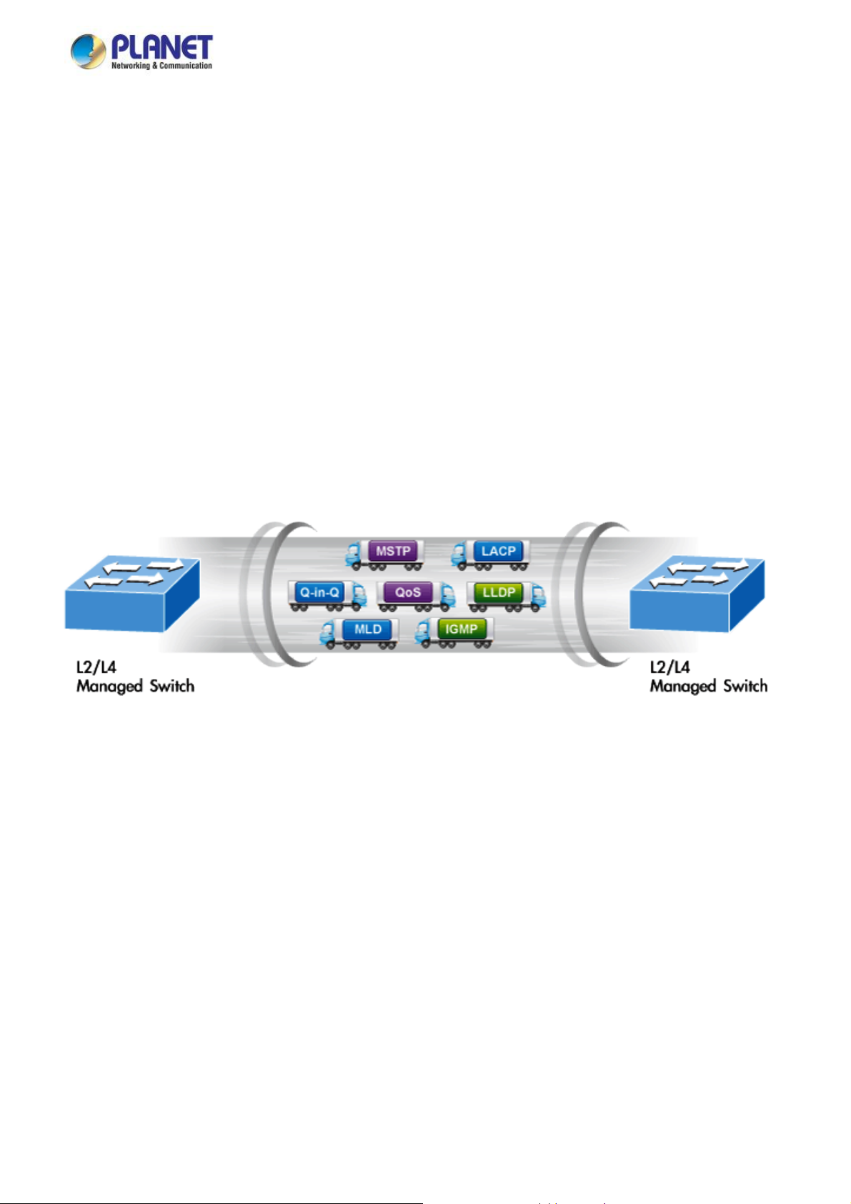
Robust Layer 2 Features
PLANET LRP Managed Switch can be programmed for advanced switch management functions such as dynamic port link
aggregation, 802.1Q VLAN and Q-in-Q VLAN, Multiple Spanning Tree Protocol (MSTP), Loop and BPDU Guard, IGMP
Snooping, and MLD Snooping. Via the link aggregation, PLANET LRP Managed Switch allows the operation of a high-speed
trunk to combine with multiple ports such as an 8Gbps fat pipe, and supports fail-over as well. Also, the Link Layer Discovery
Protocol (LLDP) is the Layer 2 Protocol included to help discover basic information about neighboring devices on the local
broadcast domain.
Efficient Traffic Control
PLANET LRP Managed Switch is loaded with robust QoS features and powerful traffic management to enhance services to
business-class data, voice, and video solutions. The functionality includes broadcast/multicast storm control, per port
bandwidth control, IP DSCP QoS priority and remarking. It guarantees the best performance for VoIP and video stream
transmission, and empowers the enterprises to take full advantage of the limited network resources.
Powerful Security
PLANET LRP Managed Switch offers comprehensive IPv4 / IPv6 Layer 2 to Layer 4 Access Control List (ACL) for enforcing
security to the edge. It can be used to restrict network access by denying packets based on source and destination IP address,
TCP/UDP ports or defined typical network applications. Its protection mechanism also comprises 802.1X port-based user and
device authentication, which can be deployed with RADIUS to ensure the port level security and block illegal users. With the
Protected Port function, communication between edge ports can be prevented to guarantee user privacy. Furthermore, Port
Security function allows to limit the number of network devices on a given port.
14
Page 15

User’s Manual of LRP-822CS/LRP-1622CS
anced Network Security
Adv
PLANET LRP Managed Switch also provides DHCP Snooping, IP Source Guard and Dynamic ARP Inspection functions to
prevent IP snooping from attack and discard ARP packets with invalid MAC address. The network administrators can now build
highly-secured corporate networks with considerably less time and effort than before.
Friendly and Secure Management
For efficient management, PLANET LRP Managed Switch is equipped with console, Web, Telnet and SNMP management
interfaces. With the built-in Web-based management interface, PLANET LRP Managed Switch offers an easy-to-use,
platform-independent management and configuration facility. By supporting the standard Simple Network Management Protocol
(SNMP), the switch can be managed via any standard management software. For text-based management, the switch can be
accessed via Telnet and the console port. Moreover, PLANET LRP Managed Switch offers secure remote management by
supporting SSH, SSL and SNMP v3 connections which encrypt the packet content at each session.
Flexibility and Long-distance Extension Solution
PLANET LRP Managed Switch provides two Gigabit TP interfaces supporting 10/100/1000BASE-T RJ45 copper to be
connected with surveillance network devices such as NVR, Video Streaming Server or NAS to facilitate surveillance
management. Or through another two dual-speed fiber SFP slots, it can connect with
the 100BASE-FX/1000BASE-SX/LX SFP (Small Form-factor Pluggable) fiber transceiver to uplink to backbone switch and
monitoring center in long distance. The distance can be extended from 550 meters to 2 kilometers (multi-mode fiber) and up to
10/20/30/40/50/70/120 kilometers (single-mode fiber or WDM fiber). The LRP Managed Switch is well suited for applications
within the enterprise data centers and distributions.
Intelligent SFP Diagnosis Mechanism
PLANET LRP Managed Switch also supports SFP-DDM (Digital Diagnostic Monitor) function that can easily monitor real-time
parameters of the SFP for network administrator, such as optical output power, optical input power, temperature, laser bias
current and transceiver supply voltage.
15
Page 16

User’s Manual of LRP-822CS/LRP-1622CS
1.3 How to Use This Manual
This User Manual is structured as follows:
Section 2, INSTALLATION
The section explains the functions of the Switch and how to physically install the LRP Managed Switch.
Section 3, SWITCH MANAGEMENT
The section contains the information about the software function of the LRP Managed Switch.
Section 4, WEB CONFIGURATION
The section explains how to manage the LRP Managed Switch by Web interface.
Section 5, SWITCH OPERATION
The chapter explains how to do the switch operation of the LRP Managed Switch.
Section 6, TROUBLESHOOTING
The chapter explains how to troubleshoot the LRP Managed Switch.
Appendix A
The section contains cable information of the LRP Managed Switch.
1.4 Product Features
Physical Port
■ 100Mbps BNC female ports with Long Reach PoE Injector function
■ 2 10/100/1000BASE-T Gigabit RJ45 copper ports
■ 2 100/1000BASE-X mini-GBIC/SFP slots
■ RJ45 console interface for switch basic management and setup
Long Reach Power over Ethernet
■ Supports PoE power up to 36 watts for each PoE port
■ Remote power feeding up to 1 kilometer with 5C2V/RG6 75Ω coaxial cable
■ Long Reach PoE Management
Total Long Reach PoE power budget control
Per port Long Reach PoE function enable/disable
Long Reach PoE port power feeding priority
Per Long Reach PoE port power limitation
Long Reach PD alive check
Long Reach PoE schedule
16
Page 17

User’s Manual of LRP-822CS/LRP-1622CS
Layer 2 Features
■ Prevents packet loss with back pressure (half-duplex) and IEEE 802.3x pause frame flow control (full-duplex)
■ High performance Store and Forward architecture, broadcast storm control, runt/CRC filtering that eliminates
erroneous packets to optimize the network bandwidth
■ Supports VLAN
- IEEE 802.1Q tagged VLAN
- Provider Bridging (VLAN Q-in-Q) support (IEEE 802.1ad)
- Protocol VLAN
- Voice VLAN
- Private VLAN
- Management VLAN
- GVRP
■ Supports Spanning Tree Protocol
- STP (Spanning Tree Protocol)
- RSTP (Rapid Spanning Tree Protocol)
- MSTP (Multiple Spanning Tree Protocol)
- STP BPDU Guard, BPDU Filtering and BPDU Forwarding
■ Supports Link Aggregation
IEEE 802.3ad Link Aggregation Control Protocol (LACP)
Cisco ether-channel (static trunk)
Maximum 4 trunk groups, up to 4 ports per trunk group
■ Provides port mirror (many-to-1)
■ Loop protection to avoid broadcast loops
Quality of Service
■ Ingress/Egress rate limit per port bandwidth control
■ Storm control support
Broadcast/Unknown unicast/Unknown multicast
■ Traffic classification
- IEEE 802.1p CoS
- ToS/DSCP/IP Precedence of IPv4/IPv6 packets
■ Strict priority and Weighted Round Robin (WRR) CoS policies
Multicast
■ Supports IGMP snooping v2 and v3
■ Supports MLD snooping v1, v2
■ IGMP querier mode support
■ IGMP snooping port filtering
■ MLD snooping port filtering
17
Page 18

User’s Manual of LRP-822CS/LRP-1622CS
Security
■ Authentication
IEEE 802.1x port-based network access authentication
Built-in RADIUS client to co-operate with the RADIUS servers
RADIUS/TACACS+ login user access authentication
■ Access Control List
IPv4/IPv6 IP-based ACL
MAC-based ACL
■ MAC Security
Static MAC
MAC filtering
■ Port security for source MAC address entries filtering
■ DHCP snooping to filter untrusted DHCP messages
■ Dynamic ARP inspection discards ARP packets with invalid MAC address to IP address binding
■ IP source guard prevents IP spoofing attacks
■ DoS attack prevention
■ SSH / SSL
Management
■ IPv4 and IPv6 dual stack management
■ Switch management interface
- Web switch management
- Telnet command line interface
- SNMP v1, v2c and v3
- SSH / SSL secure access
■ User privilege levels control
■ Built-in Trivial File Transfer Protocol (TFTP) client
■ BOOTP and DHCP for IP address assignment
■ System maintenance
- Firmware upload/download via HTTP/TFTP
- Configuration upload/download through Web interface
- Dual images
- Hardware reset button for system reboot or reset to factory default
■ SNTP Network Time Protocol
■ Cable diagnostics
■ Link Layer Discovery Protocol (LLDP) and LLDP-MED
■ SNMP trap for interface linkup and linkdown notification
■ Event message logging to remote Syslog server
■ Four RMON groups (history, statistics, alarms and events)
■ PLANET Smart Discovery utility
■ Smart fan with speed control
18
Page 19
User’s Manual of LRP-822CS/LRP-1622CS
1.5 Product Specifications
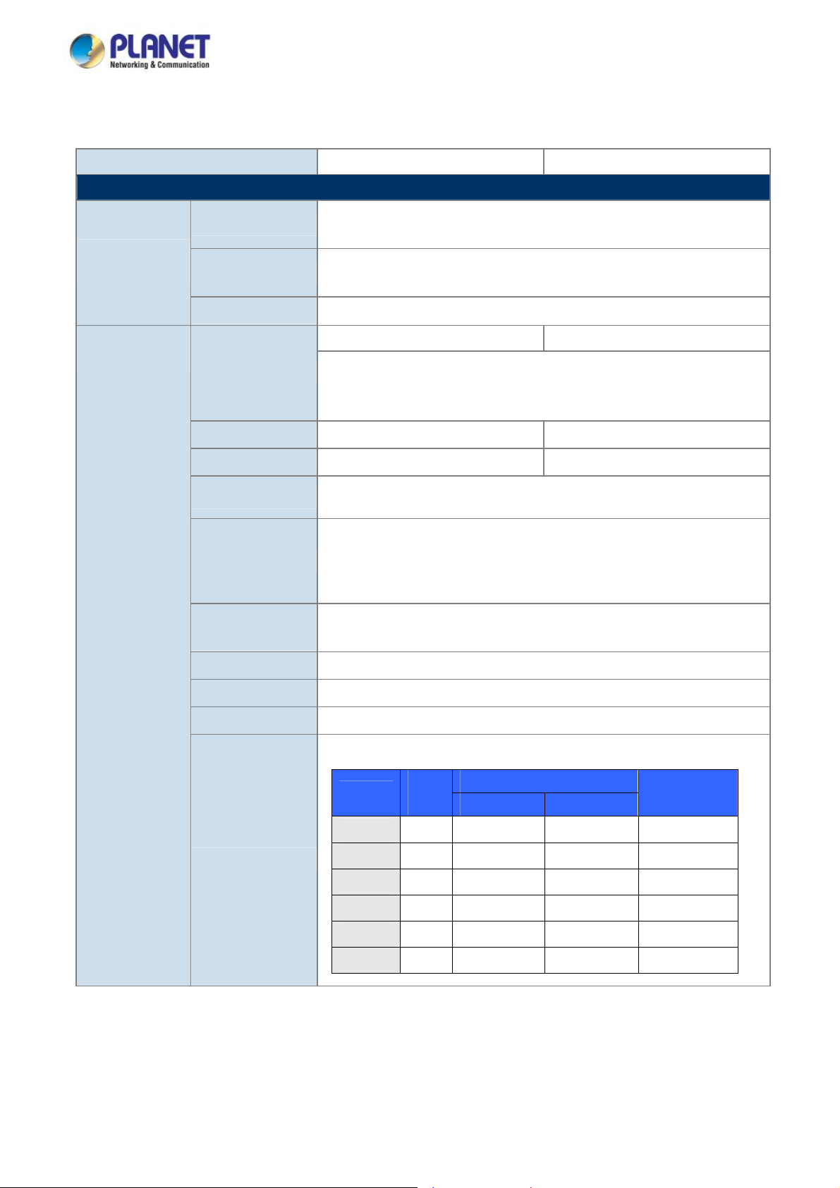
Model LRP-822CS LRP-1622CS
Hardware Specifications
Ethernet
Interfaces
Long Reach PoE
Interfaces
Copper
Fiber Optic
Jumbo Frame
Connectivity
Power Output
Total Power Budget
Cabling
Maximum Distance
Long Reach
Ethernet Standard
2 x 10/100/1000BASE-T RJ45
Auto-negotiation/ Auto-MDI/MDI-X
2 x 100/1000BASE-X SFP slot
Supports 100/1000Mbps dual mode and DDM
10Kbytes with GE1 to GE4
8 x BNC female connectors 16 x BNC female connectors
Long Reach PoE over coaxial PSE (Power Source Equipment)
BNC center pole : DC+ / Hi
BNC shield : DC - / Lo
Per port 54V DC, 36 watts max. Per port 52V DC, 36 watts max.
240 watts (max.) 440 watts (max.)
Coaxial cable: 75 ohm
RG-6/U cable (Recommended)
Max. 200m with PoE+ output (1,640ft.)
Max. 400m with PoE output (2,624ft.)
Max. 1000m with PoE output (3,280ft.)
Max. 1200m with data output only (3,937ft.)
IEEE 1901
Modulation Type Wavelet-OFDM
Security 128-bit AES encryption
Frequency Band 2 ~ 28MHz
[LRP-822CS]
Cable
Type
RG6
Performance
Distance
200m
400m RG6
600m RG6
800m RG6
1000m RG6
1200m RG6
Data Rate*
TX** RX**
91.8Mbps 81.1Mbps
85.5Mbps 66.9Mbps 18.7W
76.5Mbps 54.2Mbps 15.0W
67.9Mbps 49.2Mbps 10.4W
26.6Mbps 25.6Mbps 7.8W
25.6Mbps 25.0Mbps ---
LRP-101CE
PoE Output*
22.9W
19
Page 20
User’s Manual of LRP-822CS/LRP-1622CS
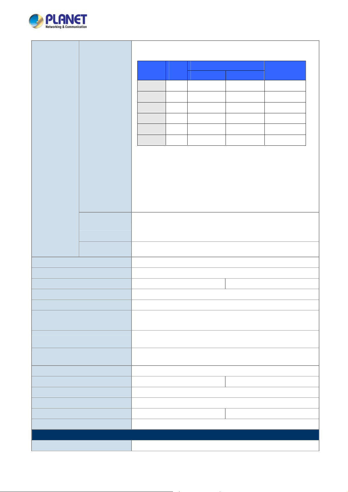
[LRP-1622CS]
Distance
200m
Cable
Type
RG6
74.8Mbps 81.7Mbps
Data Rate*
TX** RX**
LRP-101CE
PoE Output*
19.8W
400m RG6
600m RG6
800m RG6
1000m RG6
1200m RG6
* The actual data rate and PoE output vary on the quality of the copper wire and
environmental factors. The performance result above is based on the testing via
the RG-6/U coaxial cable.
** TX: LRP-822CS to LRP-101CE; RX: LRP-101CE to LRP-822CS.
Up to 4 LRP extenders within 1km RG-6/U coaxial cable*
Multiple Nodes
LRP Compatibility
Console 1 x RS232-to-RJ45 serial port (115200, 8, N, 1)
* The actual extender nodes vary on the quality of the copper wire and
environmental factors.
LRP-101CE: 1-Port 10/100TX PoE PSE + 1-Port Coax Long Reach PoE
Extender
62.5Mbps 75.2Mbps
57.8Mbps 70.3Mbps
41.7Mbps 67.1Mbps
31.7Mbps 58.8Mbps
14.9Mbps 22.5Mbps
15.8W
11. 8W
7.9W
6.7W
---
Switch Architecture Store-and-Forward
Switch Fabric 9.6Gbps / non-blocking 11.2Gbps / non-blocking
Address Table 8K entries
Shared Data Buffer 4.1 megabits
Flow Control
Reset Button
LED
Dimensions (W x D x H) 440 x 300 x 44.5 mm, 1U height
Weight 4282g 4430g
Power Requirements AC 100~240V, 50/60Hz, auto-sensing
ESD Protection 6KV DC
Power Consumption 320 watts / 1091.8 BTU 540watts / 1843BTU
Enclosure Metal
Layer 2 Functions
IEEE 802.3x pause frame for full-duplex
Back pressure for half-duplex
< 5 sec: System reboot
> 5 sec: Factory default
PWR, SYS, LNK, PoE-in-Use, 1000, LNK/ACK, Fan 1 Alert, Fan 2 Alert,
PoE PWR Alert
Port Mirroring TX / RX / both
20
Page 21
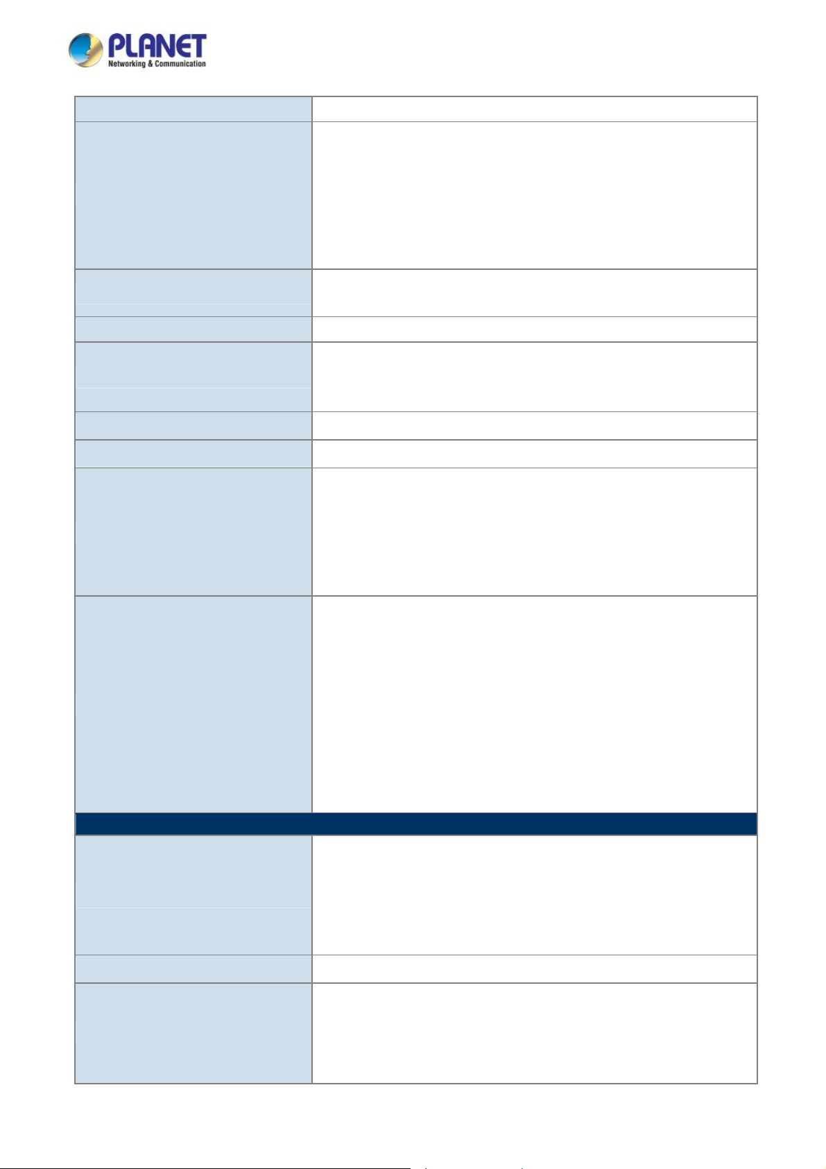
VLAN
User’s Manual of LRP-822CS/LRP-1622CS
Many-to-1 monitor
802.1Q tagged-based VLAN
Up to 256 VLAN groups, out of 4094 VLAN IDs
802.1ad Q-in-Q tunneling
Voice VLAN
Protocol VLAN
Private VLAN (Protected port)
GVRP
Link Aggregation
Spanning Tree Protocol STP / RSTP / MSTP
IGMP Snooping
MLD Snooping
Access Control List
QoS
Security
Management Functions
Basic Management Interfaces
IEEE 802.3ad LACP and static trunk
Supports 4 groups of 4-port trunk
IGMP (v2/v3) Snooping
IGMP Querier
Up to 256 multicast groups
MLD (v1/v2) Snooping, up to 256 multicast groups
IPv4/IPv6 IP-based ACL / MAC-based ACL
8 mapping ID to 8 level priority queues
- Port number
- 802.1p priority
- 802.1Q VLAN tag
- DSCP field in IP packet
Traffic classification based, strict priority and WRR
IEEE 802.1X– Port-based authentication
Built-in RADIUS client to co-operate with RADIUS server
RADIUS / TACACS+ user access authentication
IP-MAC port binding
MAC filter
Static MAC address
DHCP Snooping and DHCP Option 82
STP BPDU guard, BPDU filtering and BPDU forwarding
DoS attack prevention
ARP inspection
IP source guard
Web browser / Telnet / SNMP v1, v2c
Firmware upgrade by HTTP / TFTP protocol through Ethernet network
Remote / Local Syslog
System log
LLDP protocol
SNTP
Secure Management Interfaces
SNMP MIBs
SSH, SSL, SNMP v3
RFC 1213 MIB-II
RFC 1215 Generic Traps
RFC 1493 Bridge MIB
RFC 2674 Bridge MIB Extensions
RFC 2737 Entity MIB (Version 2)
21
Page 22

User’s Manual of LRP-822CS/LRP-1622CS
Standards Conformance
RFC 2819 RMON (1, 2, 3, 9)
RFC 2863 Interface Group MIB
RFC 3635 Ethernet-like MIB
Regulation Compliance
Standards Compliance
Environment
Operating
Storage
FCC Part 15 Class A, CE
IEEE 1901 Broadband Power Line
IEEE 802.3 10BASE-T
IEEE 802.3u 100BASE-TX/100BASE-FX
IEEE 802.3z Gigabit SX/LX
IEEE 802.3ab Gigabit 1000T
IEEE 802.3x flow control and back pressure
IEEE 802.3ad port trunk with LACP
IEEE 802.1D Spanning Tree Protocol
IEEE 802.1w Rapid Spanning Tree Protocol
IEEE 802.1s Multiple Spanning Tree Protocol
IEEE 802.1p Class of Service
IEEE 802.1Q VLAN tagging
IEEE 802.1X Port Authentication Network Control
IEEE 802.1ab LLDP
RFC 768 UDP
RFC 793 TFTP
RFC 791 IP
RFC 792 ICMP
RFC 2068 HTTP
RFC 1112 IGMP version 1
RFC 2236 IGMP version 2
RFC 3376 IGMP version 3
RFC 2710 MLD version 1
RFC 3810 MLD version 2
Temperature: 0 ~ 50 degrees C
Relative Humidity: 5 ~ 95% (non-condensing)
Temperature: -10 ~ 70 degrees C
Relative Humidity: 5 ~ 95% (non-condensing)
22
Page 23
User’s Manual of LRP-822CS/LRP-1622CS
2. INSTALLATION
This section describes the hardware features and installation of the LRP Managed Switch on the desktop or rack mount. For
easier management and control of the LRP Managed Switch, familiarize yourself with its display indicators, and ports. Front
panel illustrations in this chapter display the unit LED indicators. Before connecting any network device to the LRP Managed
Switch, please read this chapter completely.
2.1 Hardware Description
2.1.1 Switch Front Panel
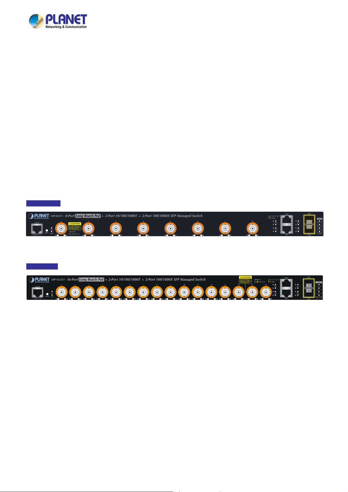
The front panel provides a simple interface monitoring of the LRP Managed Switch. Figures 2-1-1A and 2-1-1B show the front
panels of the LRP Managed Switches.
Front Panel
Figure 2-1-1A LRP-822CS Front Panel
Front Panel
gure 2-1-1B LRP-1622CS Front Panel
Fi
■ Long Reach PoE BNC Interface
BNC female port, 5C2V/RG6 75Ω coaxial cable: Up to 1 kilometer.
■ Gigabit TP Interface
10/100/1000BASE-T Copper, RJ45 Twisted-pair: Up to 100 meters.
■ 100/1000BASE-X SFP Slots
Each of the SFP (Small Form-factor Pluggable) slots supports dual-speed, 1000BASE-SX / LX or 100BASE-FX
- For 1000BASE-SX/LX SFP transceiver module: From 550 meters (multi-mode fiber) to 10/30/50/70/120 kilometers
(single-mode fiber).
- For 100BASE-FX SFP transceiver module: From 2 kilometers (multi-mode fiber) to 20/40/60 kilometers (single-mode
fiber).
23
Page 24

User’s Manual of LRP-822CS/LRP-1622CS
■ Console Port
The console port is a RJ45 port connector. It is an interface for connecting a terminal directly. Through the console port, it
provides rich diagnostic information including IP Address setting, factory reset, port management, link status and system
setting.
Users can use the attached DB9 to RJ45 console cable in the package and connect to the console port on the device. After
the connection, users can run any terminal emulation program (Hyper Terminal, ProComm Plus, Telix, Winterm and so on)
to enter the startup screen of the device.
■ Reset Button
On the left of the front panel, the reset button is designed to reboot the LRP Managed Switch without turning off and on the
power. The following is the summary table of the Reset button functions:
Reset Button Pressed and Released Function
< 5 sec: System Reboot Reboot the LRP Managed Switch.
Reset the LRP Managed Switch to the Factory Default
configuration. The LRP Managed Switch will then reboot and
load the default settings shown below:
> 5 sec: Factory Default
。 Default Username: admin
。 Default Password: admin
。 Default IP Address: 192.168.0.100
。 Subnet Mask: 255.255.255.0
。 Default Gateway: 192.168.0.254
24
Page 25
User’s Manual of LRP-822CS/LRP-1622CS
2.1.2 LED Indications
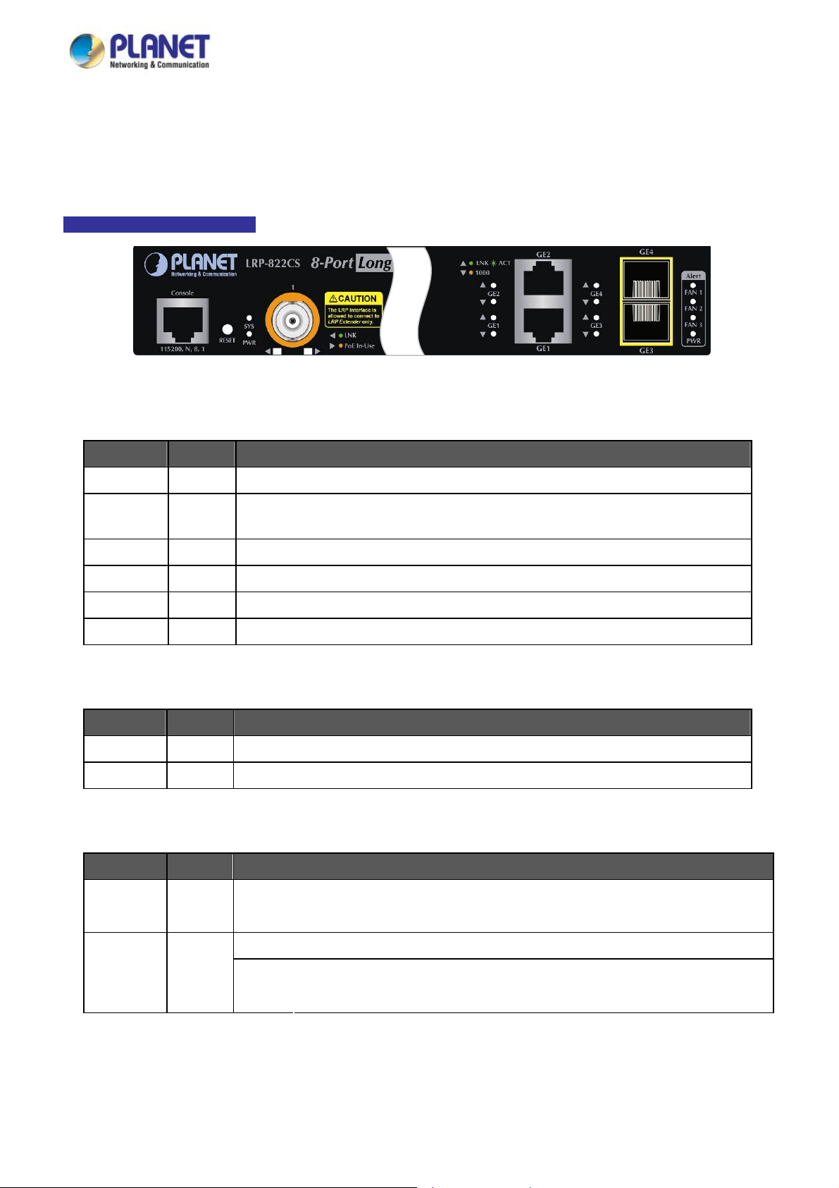
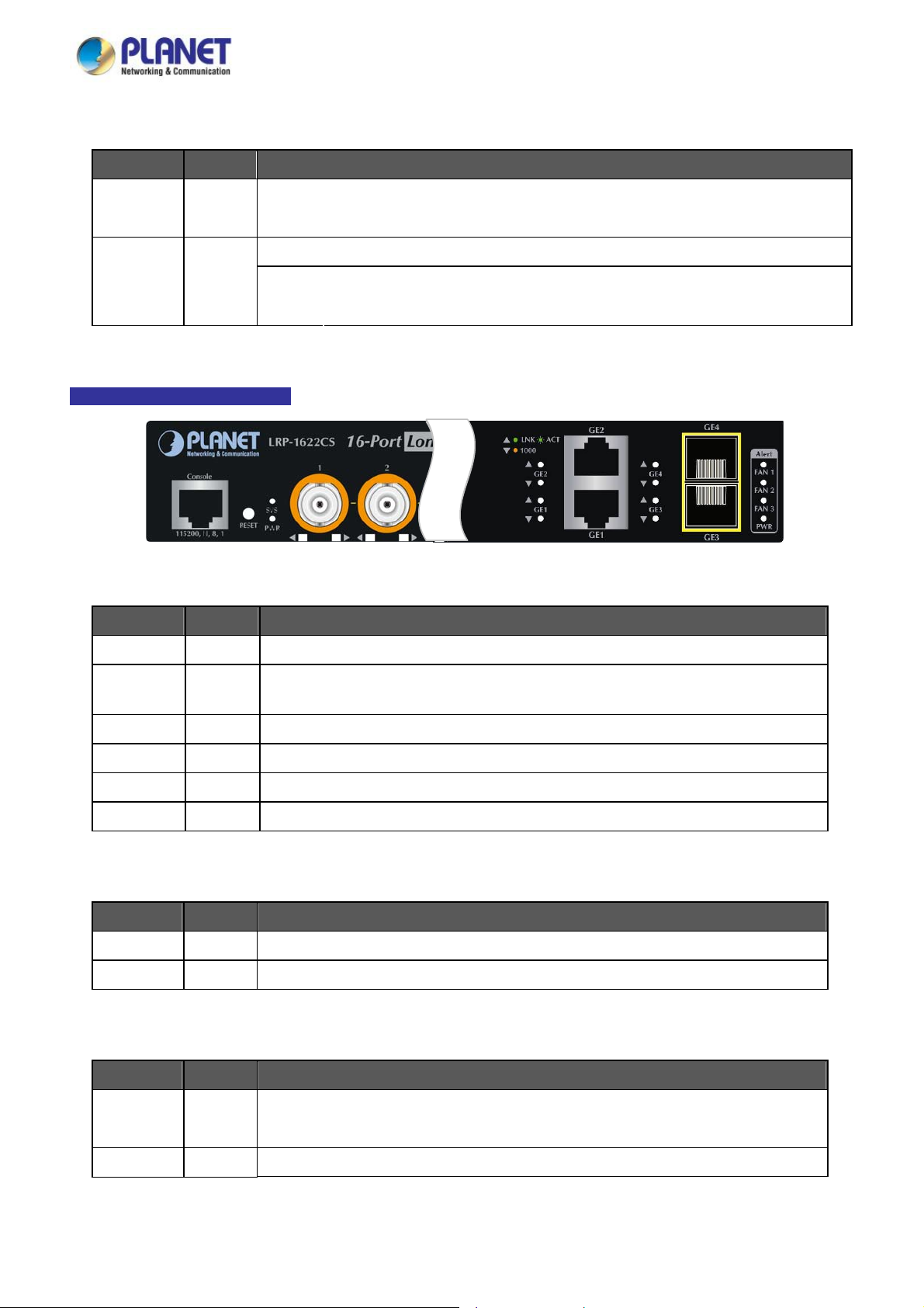
The front panel LEDs indicates instant status of port links, data activity and system power; it helps monitor and troubleshoot
when needed. Figures 2-1-2A and 2-1-2B show the LED indications of these LRP Managed Switches.
LRP-822CS LED Indication
Figure 2-1-2 LRP-822CS LED Panel
■ System / Alert
LED Color Function
PWR Green
SYS Green
FAN 1 Red
FAN 2 Red
FAN 3 Red
PWR Red
■ Long Reach PoE Interfaces (Port-1 to Port-8)
LED Color Function
LNK Green Lights
Lights to indicate that the Switch has power.
Lights to indicate the system is working.
Off to indicate the system is booting.
Lights to indicate that Fan 1 is down.
Lights to indicate that Fan 2 is down.
Lights to indicate that Fan 3 is down.
Lights to indicate that the PoE Power is down.
To indicate the link through that port is successfully established.
PoE Orange Lights
■ 10/100/1000BASE-T Interfaces (GE1 to GE2)
LED Color Function
Lights
LNK/ACT Green
Blinking
Lights To indicate that the port is operating at 1000Mbps.
Lights When LNK/ACT LED lights up, it indicates that the port is operating at 10/100Mbps.1000 Orange
Off
To indicate the port is providing DC in-line power.
To indicate the link through that port is successfully established.
To indicate that the switch is actively sending or receiving data over that port.
When LNK/ACT LED is off, it indicates that the port is linkdown.
25
Page 26
User’s Manual of LRP-822CS/LRP-1622CS
■ 1000BASE-SX/LX SFP Interfaces (GE3 to GE4)
LED Color Function
LNK/ACT Green
Lights
Blinking
Lights To indicate that the port is operating at 1000Mbps.
Lights When LNK/ACT LED lights up, it indicates that the port is operating at 10/100Mbps.1000 Orange
Off
LRP-1622CS LED Indication
■ System / Alert
LED Color Function
To indicate the link through that port is successfully established.
To indicate that the switch is actively sending or receiving data over that port.
When LNK/ACT LED is off, it indicates that the port is linkdown.
Figure 2-1-2B LRP-1622CS LED Panel
PWR Green
SYS Green
FAN 1 Red
FAN 2 Red
FAN 3 Red
PWR Red
■ Long Reach PoE Interfaces (Port-1 to Port-16)
LED Color Function
LNK Green Lights
PoE Orange Lights
■ 10/100/1000BASE-T Interfaces (GE1 to GE2)
LED Color Function
Lights to indicate that the Switch has power.
Lights to indicate the system is working.
Off to indicate the system is booting.
Lights to indicate that Fan 1 is down.
Lights to indicate that Fan 2 is down.
Lights to indicate that Fan 3 is down.
Lights to indicate that the PoE Power is down.
To indicate the link through that port is successfully established.
To indicate the port is providing DC in-line power.
LNK/ACT Green
1000 Orange Lights To indicate that the port is operating at 1000Mbps.
Lights
Blinking
To indicate the link through that port is successfully established.
To indicate that the switch is actively sending or receiving data over that port.
26
Page 27
User’s Manual of LRP-822CS/LRP-1622CS
Lights
Off
■ 1000BASE-SX/LX SFP Interfaces (GE3 to GE4)
LED Color Function
LNK/ACT Green
1000 Orange
Lights
Blinking
Lights To indicate that the port is operating at 1000Mbps.
Lights
Off
If LNK/ACT LED lights up, it indicates that the port is operating at 10/100Mbps.
If LNK/ACT LED is off, it indicates that the port is linkdown.
To indicate the link through that port is successfully established.
To indicate that the switch is actively sending or receiving data over that port.
If LNK/ACT LED lights up, it indicates that the port is operating at 100Mbps.
If LNK/ACT LED is off, it indicates that the port is linkdown.
2.1.3 Switch Rear Panel
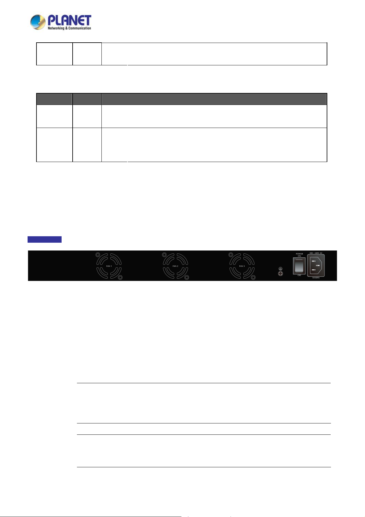
The rear panel of the LRP Managed Switch has an AC power socket, which accepts voltage from 100 to 240V AC at 50-60Hz.
Figure 2-1-3 shows the rear panel of these LRP Managed Switches.
Rear Panel
Figure 2-1-3 Rear Panel of LRP-822CS/LRP-1622CS
■ AC Power Receptacle
For compatibility with electric service in most areas of the world, the LRP Managed Switch’s power supply automatically
adjusts to line power in the range of 100-240V AC at 50/60 Hz.
Plug the female end of the power cord firmly into the receptacle on the rear panel of the LRP Managed Switch. Plug the
other end of the power cord into an electrical outlet and the power will be ready.
The device is a power-required device, which means it will not work till it is powered. If your networks
Power Notice:
should be active all the time, please consider using UPS (Uninterrupted Power Supply) for your device.
It will prevent you from network data loss or network downtime.
Power Notice:
In some areas, installing a surge suppression device may also help to protect your LRP Managed
Switch from being damaged by unregulated surge or current to the LRP Managed Switch.
27
Page 28
User’s Manual of LRP-822CS/LRP-1622CS
2.2 Installing the Switch
This section describes how to install your LRP Managed Switch and make connections to the LRP Managed Switch. Please
read the following topics and perform the procedures in the order being presented. To install your LRP Managed Switch on a
desktop or shelf, simply complete the following steps.
2.2.1 Desktop Installation
To install the LRP Managed Switch on desktop or shelf, please follow these steps:
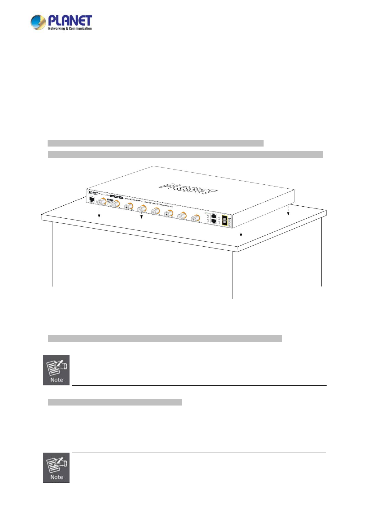
Step 1: Attach the rubber feet to the recessed areas on the bottom of the LRP Managed Switch.
Step 2: Place the LRP Managed Switch on the desktop or the shelf near an AC power source, as shown in Figure 2-1-4.
Figure 2-1-4 Place the LRP Managed Switch on the desktop
Step 3: Keep enough ventilation space between the LRP Managed Switch and the surrounding objects.
When choosing a location, please keep in mind the environmental restrictions discussed in Chapter 1,
Section 4 under specifications.
Step 4: Connect the LRP Managed Switch to network devices.
Connect one end of a standard network cable to the 10/100/1000 RJ45 ports and standard coaxial cable to LRP ports on
the front of the LRP Managed Switch. Connect the other end of the cable to the network devices such as printer server,
workstation or router.
Connection to the LRP Managed Switch requires UTP Category 5 network cabling with RJ45 tips. For
more information, please see the Cabling Specification in Appendix A.
28
Page 29
User’s Manual of LRP-822CS/LRP-1622CS
Step 5: Supply power to the LRP Managed Switch.
Connect one end of the power cable to the LRP Managed Switch. Connect the power plug of the power cable to a
standard wall outlet. When the LRP Managed Switch receives power, the Power LED should remain solid Green.
2.2.2 Rack Mounting
To install the LRP Managed Switch in a 19-inch standard rack, please follow the instructions described below.
Step 1: Place the LRP Managed Switch on a hard flat surface, with the front panel positioned towards the front side.
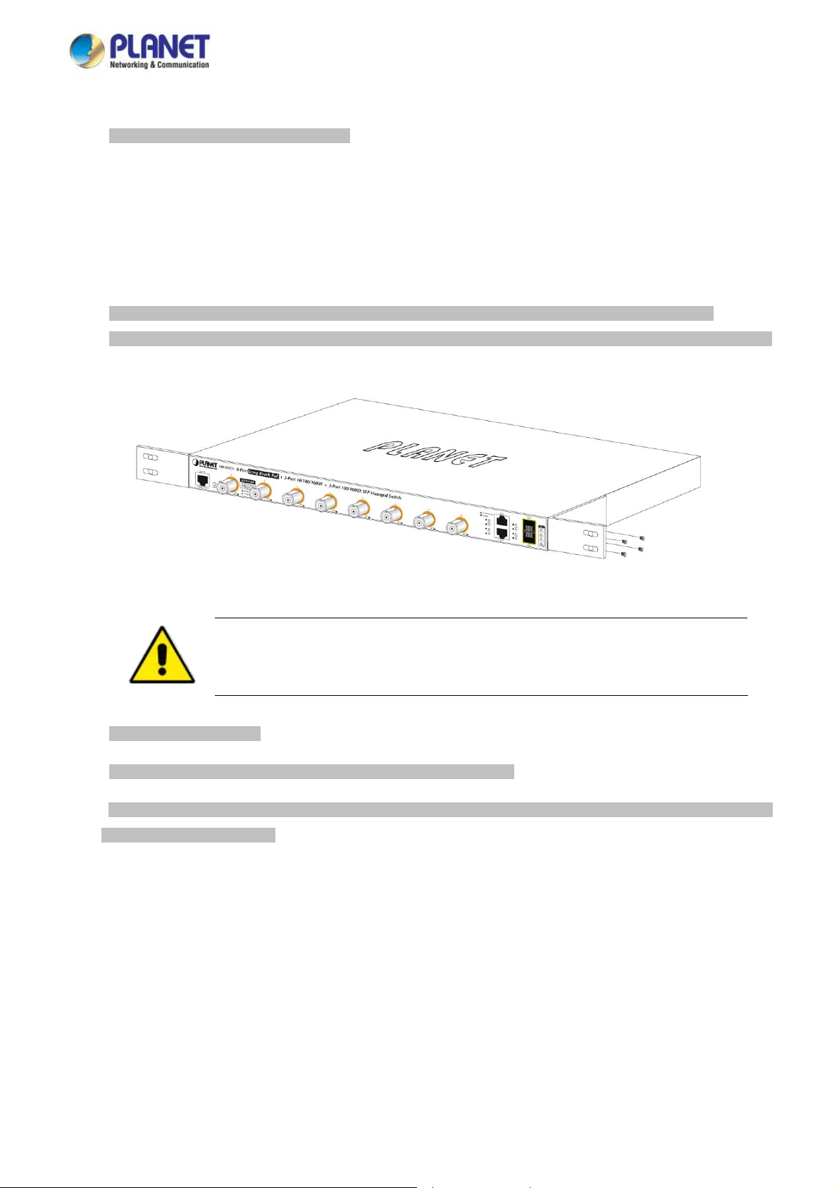
Step 2: Attach the rack-mount bracket to each side of the LRP Managed Switch with supplied screws attached to the package.
Figure 2-1-5 shows how to attach brackets to one side of the LRP Managed Switch.
Figure 2-1-5 Attach Brackets to the LRP Managed Switch.
You must use the screws supplied with the mounting brackets. Damage caused to the parts by
using incorrect screws would invalidate the warranty.
Step 3: Secure the brackets tightly.
Step 4: Follow the same steps to attach the second bracket to the opposite side.
Step 5: After the brackets are attached to the LRP Managed Switch, use suitable screws to securely attach the brackets to the
rack, as shown in Figure 2-1-6.
29
Page 30
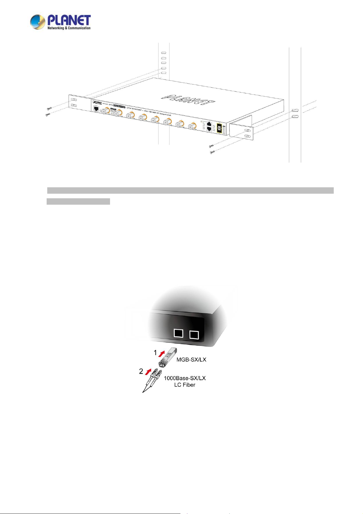
User’s Manual of LRP-822CS/LRP-1622CS
Figure 2-1-6 Mounting LRP Managed Switch in a Rack
Step 6: Proceeds with Steps 4 and 5 of session 2.2.1 Desktop Installation to connect the network cabling and supply power to
the LRP Managed Switch.
2.2.3 Installing the SFP transceiver
The sections describe how to insert an SFP transceiver into an SFP slot. The SFP transceivers are hot-pluggable and
hot-swappable. You can plug in and out the transceiver to/from any SFP port without having to power down the LRP Managed
Switch as Figure 2-1-7 shows.
Figure 2-1-7 Plug in the SFP transceiver
Approved PLANET SFP Transceivers
PLANET LRP Managed Switch supports both single mode and multi-mode SFP transceivers. The following list of approved
PLANET SFP transceivers is correct at the time of publication:
30
Page 31

User’s Manual of LRP-822CS/LRP-1622CS
Gigabit SFP Transceiver Modules
MGB-GT
MGB-SX
MGB-LX
MGB-L50
MGB-L70
MGB-L120
MGB-LA10
MGB-LA20
MGB-LB20
MGB-LA40
MGB-LB40
SFP-Port 1000BASE-T Module
SFP-Port 1000BASE-SX mini-GBIC module
SFP-Port 1000BASE-LX mini-GBIC module
SFP-Port 1000BASE-LX mini-GBIC module – 50km
SFP-Port 1000BASE-LX mini-GBIC module – 70km
SFP-Port 1000BASE-LX mini-GBIC module – 120km
SFP-Port 1000BASE-LX (WDM,TX:1310nm) – 10km
SFP-Port 1000BASE-LX (WDM,TX:1310nm) – 20km
SFP-Port 1000BASE-LX (WDM,TX:1550nm) – 20km
SFP-Port 1000BASE-LX (WDM,TX:1310nm) – 40km
SFP-Port 1000BASE-LX (WDM,TX:1550nm) – 40km
Fast Ethernet SFP Transceiver Modules
MFB-FX
MFB-F20
MFB-F60
SFP-Port 100BASE-FX Transceiver – 2km
SFP-Port 100BASE-FX Transceiver – 20km
SFP-Port 100BASE-FX Transceiver – 60km
MFB-FA20
MFB-FB20
1. Before we connect LRP Managed Switch to the other network device, we have to make sure both sides of the SFP
transceivers are with the same media type, for example, 1000BASE-SX to 1000BASE-SX, 1000BASE-LX to
1000BASE-LX.
2. Check whether the fiber-optic cable type matches with the SFP transceiver requirement.
SFP-Port 100BASE-BX Transceiver (WDM,TX:1310nm) – 20km
SFP-Port 100BASE-BX Transceiver (WDM,TX:1550nm) – 20km
It is recommended to use PLANET SFP on the LRP Managed Switch. If you insert an SFP
transceiver that is not supported, the LRP Managed Switch will not recognize it.
In the installation steps below, this Manual uses Gigabit SFP transceiver as an example. However,
the steps for Fast Ethernet SFP transceiver are similar.
To connect to 1000BASE-SX SFP transceiver, please use the multi-mode fiber cable with one side being the male
duplex LC connector type.
To connect to 1000BASE-LX SFP transceiver, please use the single-mode fiber cable with one side being the male
duplex LC connector type.
31
Page 32
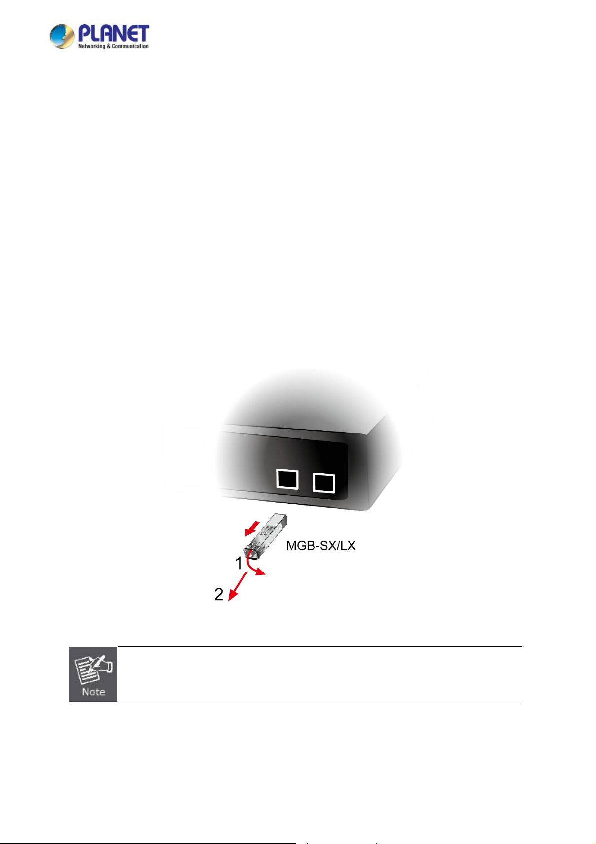
User’s Manual of LRP-822CS/LRP-1622CS
Connect the Fiber Cable
1. Insert the duplex LC connector into the SFP transceiver.
2. Connect the other end of the cable to a device with SFP transceiver installed.
3. Check the LNK/ACT LED of the SFP slot on the front of the LRP Managed Switch. Ensure that the SFP transceiver is
operating correctly.
4. Check the Link mode of the SFP port if the link fails. To function with some fiber-NICs or media converters, user has to set
the port Link mode to “1000 Force” or “100 Force”.
Remove the Transceiver Module
1. Make sure there is no network activity anymore.
2. Remove the fiber-optic cable gently.
3. Lift up the lever of the MGB module and turn it to a horizontal position.
4. Pull out the module gently through the lever.
Figure 2-1-8 How to Pull Out the SFP Transceiver
Never pull out the module without lifting up the lever of the module and turning it into a horizontal
position. Directly pulling out the module could damage the module and the SFP module slot of the
LRP Managed Switch.
32
Page 33
User’s Manual of LRP-822CS/LRP-1622CS
2.2.4 Installing the Long Reach PoE Communication
The sections describe how to insert a coaxial cable into a BNC female port. You can plug in and out the coaxial cable to/from
any BNC female port without having to power down the LRP Managed Switch.
Approved PLANET Long Reach PoE Extenders
The following list of approved PLANET Long Reach PoE extenders is correct at the time of publication:
Long Reach Ethernet Coaxial Extenders
LRP-101CE
It is recommended to use PLANET Long Reach Ethernet coaxial extenders on the LRP Managed
Switch. If you insert a coaxial extender that is not supported, the LRP Managed Switch may
damage it.
1. Before we connect LRP Managed Switch to the other network device, we have to make sure both sides of the Long
Reach Ethernet coaxial extender/transceiver are with the same media type.
2. Check whether the coaxial cable type matches with the Long Reach Ethernet coaxial extender/transceiver requirement.
To connect to LRP Managed Switch, please use the coaxial cable with 75Ω BNC plug with one side being the BNC
plug connector type.
To connect to Long Reach Ethernet coaxial extenders, please use the coaxial cable with one side being the 75Ω
BNC plug connector type.
Because there are various resistance values in the category of RG-59/U or RG-6/U cables, please
1-Port 10/100TX PoE PSE + 1-Port Coax Long Reach PoE Extender
take care of the conditions of the resistance value of cables as follows:
Coaxial Cable Type
In the installation steps below, this Manual uses Long Reach Ethernet coaxial extender as an
example.
RG-59/U Less than 30Ω/1000 ft.
RG-6/U Less than 12Ω/1000 ft
Connect the Coaxial Cable
1. Insert the coaxial cable with one side being the 75Ω BNC plug connector into the Long Reach Ethernet coaxial interface.
2. Connect the other end of the cable to a device with Long Reach Ethernet coaxial extender installed.
33
Page 34
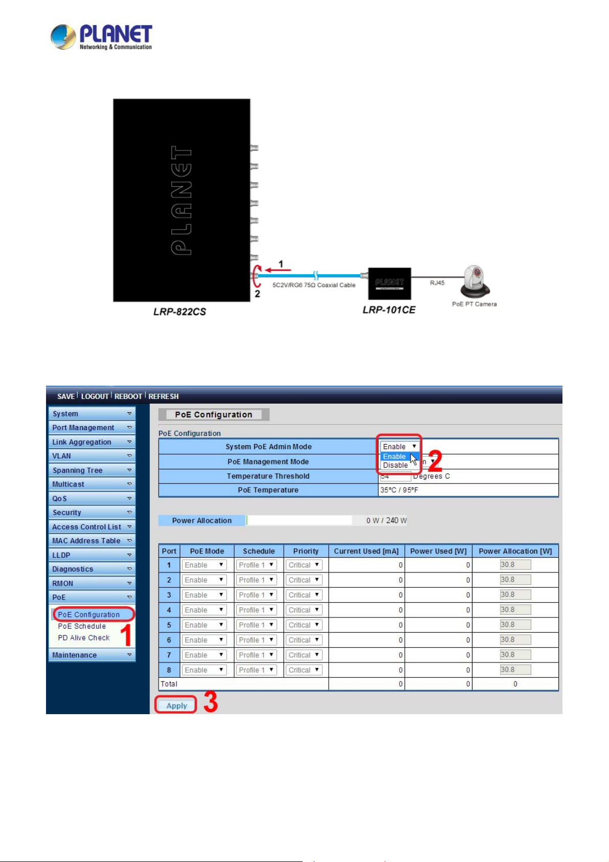
User’s Manual of LRP-822CS/LRP-1622CS
3. Tighten the BNC male connector gently.
Figure 2-1-8 How to insert the coaxial cable from LRP Managed Switch
4. Enable Long Reach Power over Ethernet function for the all LRP ports from WebUI
. Check the LNK LED of the Long Reach Power over Ethernet interface on the front of the LRP Managed Switch. Ensure
5
that the Long Reach Power over Ethernet interface is operating correctly.
34
Page 35
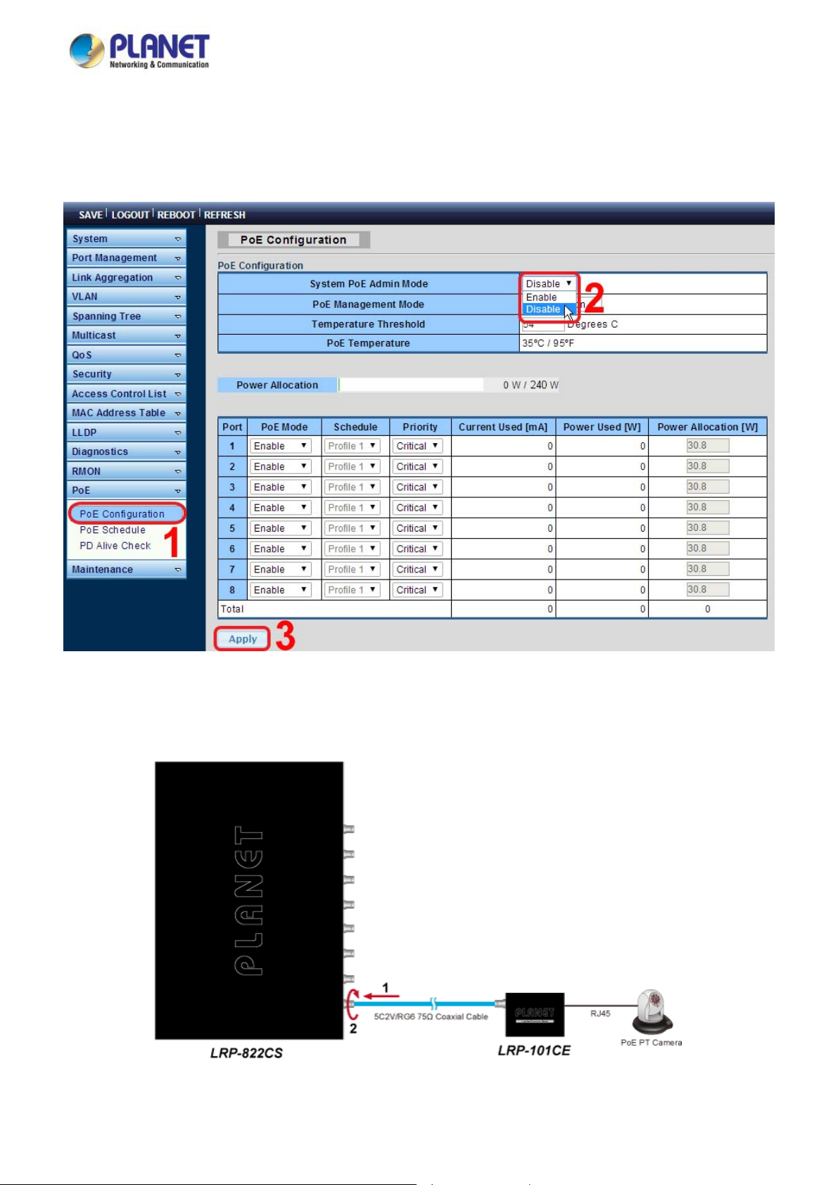
User’s Manual of LRP-822CS/LRP-1622CS
Remove the connected the Coaxial Cable
1. Make sure there is no network activity anymore.
2. Disable Long Reach Power over Ethernet function
for the all LRP ports from WebUI.
. Loosen the BNC male connector gently. 3
4. Pull out the coaxial cable gently.
Figure 2-1-8 How to pull out the coaxial cable from LRP Managed Switch
35
Page 36
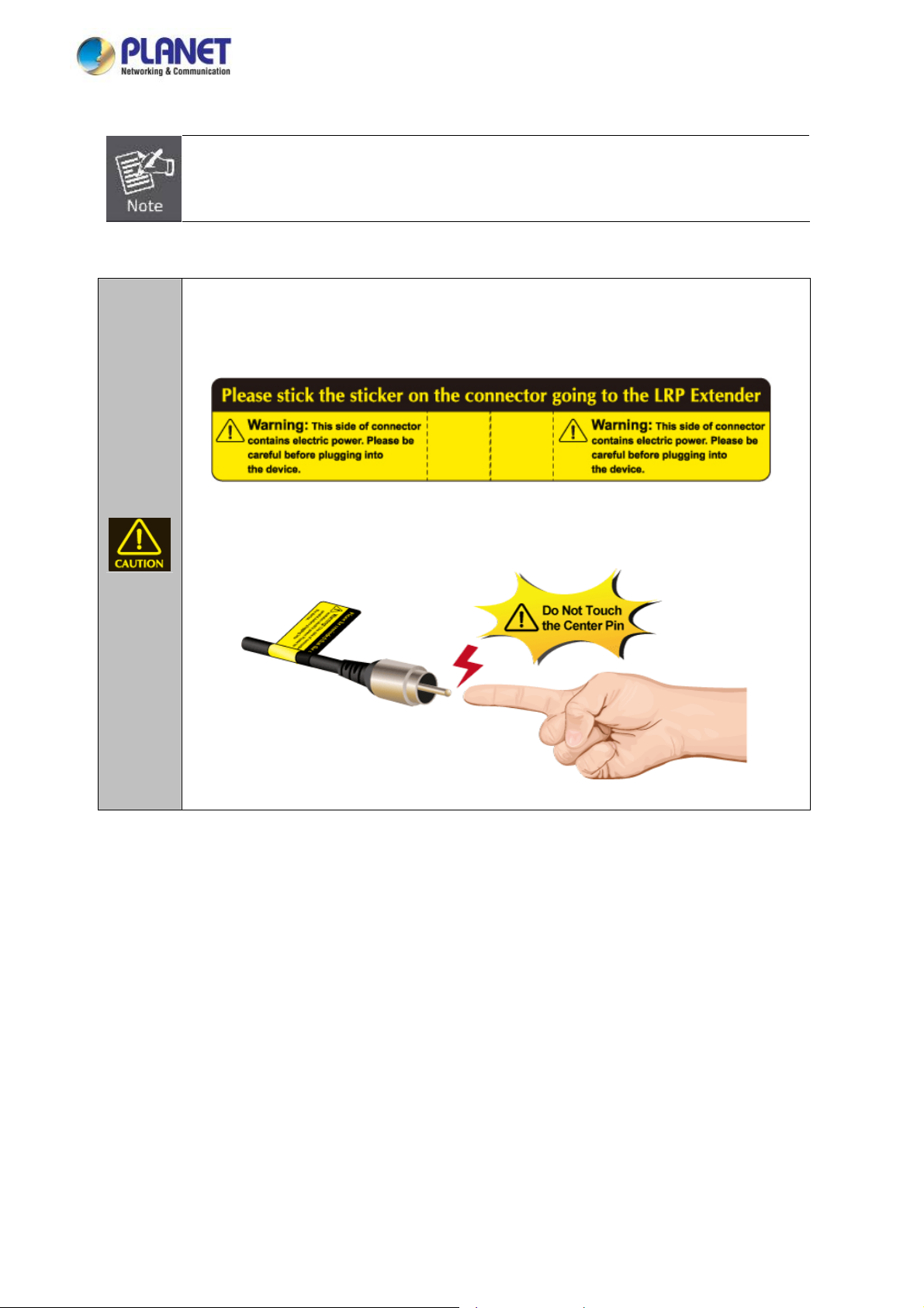
User’s Manual of LRP-822CS/LRP-1622CS
Never pull out the coaxial cable without disabling Long Reach Power over Ethernet function for the
port from WebUI. Directly pulling out the coaxial cable could damage the Long Reach Ethernet
coaxial extender and the BNC female connector of the LRP Managed Switch.
1. The package contains eight warning stickers, which should be stuck on the coaxial cable
connector before using PLANET LRP Managed Switch and LRP extender. If connected with
non-PLANET LRP series extender equipment, it might cause damage to the equipment.
2. After city. Do not touch
the LRP PoE port is enabled, the pin center of the coaxial cable has electri
the pin center or connect this end to any non- PLANET LRP equipment.
36
Page 37

User’s Manual of LRP-822CS/LRP-1622CS
3. SWITCH MANAGEMENT
T
his chapter explains the methods that you can use to configure management access to the LRP Managed Switch. It describes
th
e types of management applications and the communication and management protocols that deliver data between your
m
anagement device (workstation or personal computer) and the system. It also contains information about port connection
o
ptions.
T
his chapter covers the following topics:
Requirements
Management Access Overview
Administration Console Access
Web Management Access
SNMP Access
Standards, Protocols, and Related Reading
3.1 Requirements
Workstations running Windows 2000/XP, 2003, Vista/7/8, 2008, MAC OS9 or later, Linux, UNIX or other platforms
are compatible with TCP/IP protocols.
Workstation is installed with Ethernet NIC (Network Interface Card)
Serial Port connect (Terminal)
The above PC with COM Port (DB9 / RS232) or USB-to-RS232 converter
Ethernet Port connection
Network cables -- Use standard network (UTP) cables with RJ45 connectors.
The above Workstation is installed with Web browser and JAVA runtime environment plug-in
It is recommended to use Internet Explore 8.0 or above to access LRP Managed Switch.
37
Page 38

User’s Manual of LRP-822CS/LRP-1622CS
3.2 Management Access Overview
The LRP Managed Switch gives you the flexibility to access
An administration console
Web browser interface
An external SNMP-based network management application
The administration console and Web browser interface support are embedded in the LRP Managed Switch software and are
available for immediate use. Each of these management methods has their own advantages. Table 3-1 compares the three
management methods.
Method Advantages Disadvantages
Console
No IP address or subnet needed
Text-based
Telnet functionality and
built into Windows
95/98/N
systems
Secure
T/2000/ME/XP operating
HyperTerminal
and manage it using any or all of the following methods:
Must be near the switch or use dial-up
connection
Not convenient for remote users
Modem connection may prove to be unreliable
or slow
Web Browser
SNMP Agent
Ideal fo
Comp
Can be accessed from any location
Most visually appealing
Communicates with switch functions at Requires SN
Based on open standards Some settings require calc
r configuring the switch remotely
atible with all popular browsers
the MIB level
Table 3-1 Comparison of Management Methods
Security can be compromised (hackers need
only know the IP address and subnet mask)
May encounter lag times on poor connections
MP manager software
Least visually appealing of all three methods
Security can be compromised (hackers only
unity name) need to know the comm
ulations
38
Page 39
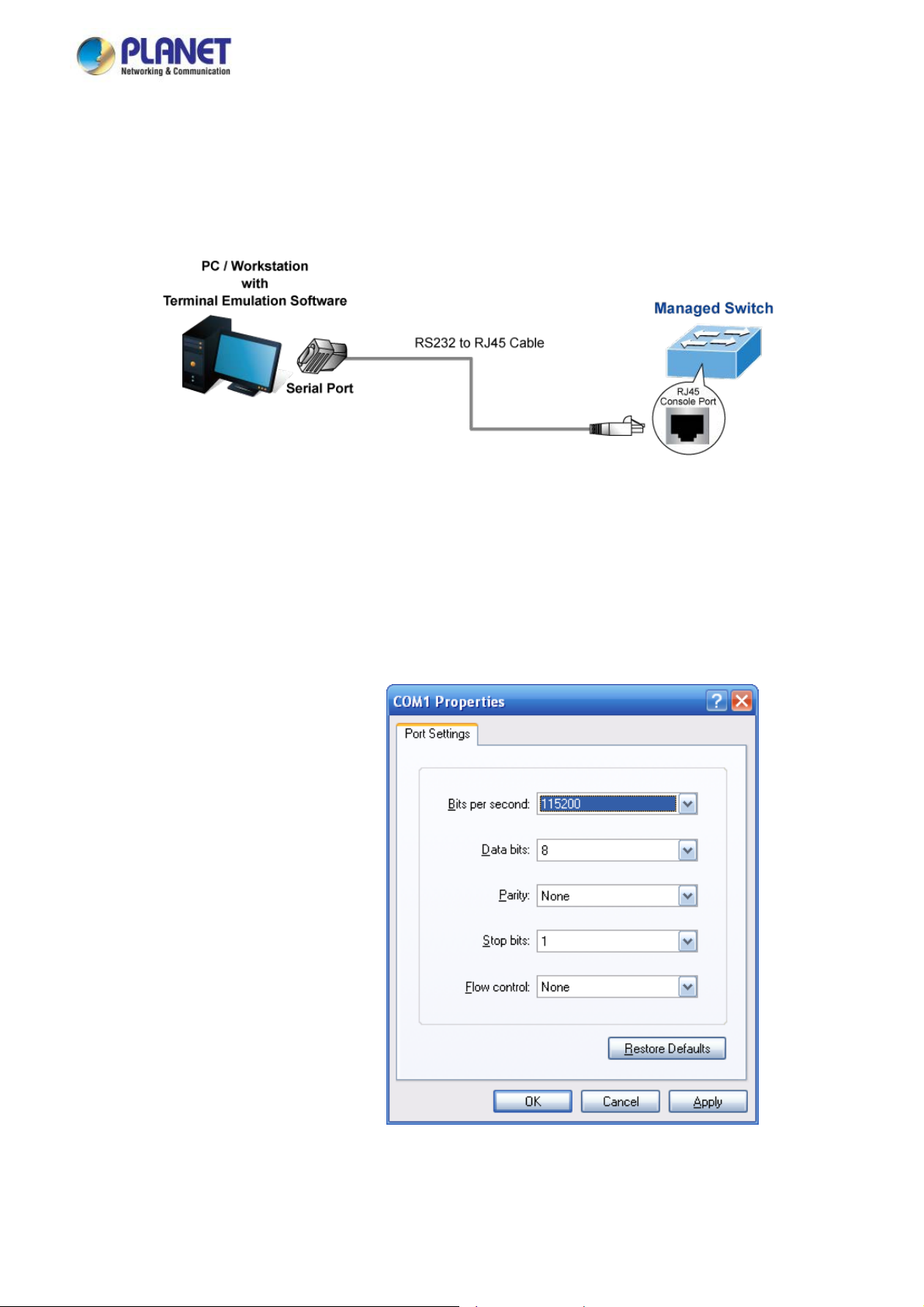
User’s Manual of LRP-822CS/LRP-1622CS
3.3 Administration Console
The administration console is an internal, character-oriented, and command line user interface for performing system
administration such as displaying statisti
console from a terminal, personal com
port.
Direct Acces
Direct access t nsole is achieved by directly connecting a terminal or a PC equipped with a
terminal-emu HyperTerminal) to the LRP Managed Switch console (serial) port. When using this
mana
gement method, a straight RS232 to RJ45 cable is required to connect the switch to the PC. After making this
connection, configur
s
o the administration co
lation program (such as
cs or changing option settings. Using this method, you can view the administration
puter, Apple Macintosh, or workstation connected to the LRP Managed Switch's console
Figure 3-1-1: Cons
ole Management
wing parameters: e the terminal-emulation program to use the follo
The default p
arameters are:
115200 bps
8 data bits
No parity
1 stop bit
Figure 3-1-2: Terminal Parameter Settings
You can change these settings, if desired, after you log on. This management method is often preferred because you can
remain connected and monitor the system during system reboots. Also, certain error messages are sent to the serial port,
39
Page 40
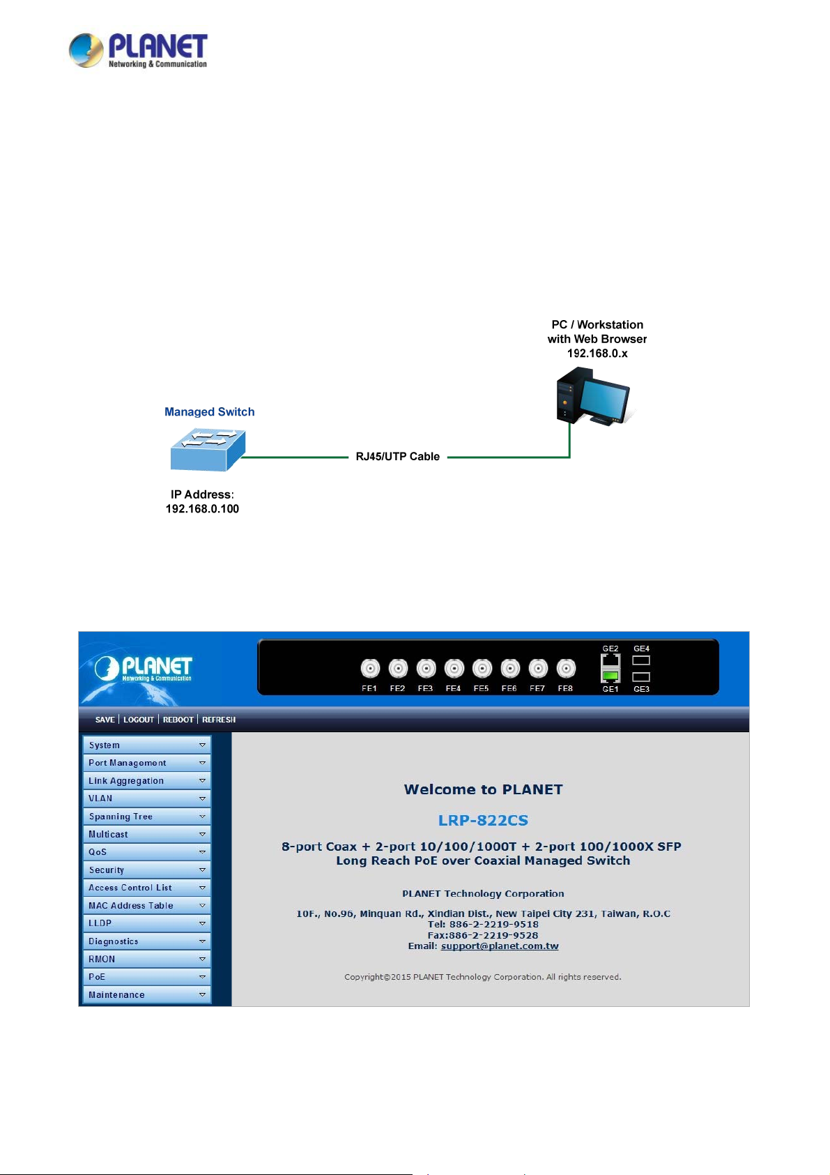
User’s Manual of LRP-822CS/LRP-1622CS
regardless of the interface through which the as
terminal-
emulator such as TIP.
lation program for connecting to th
emu
3.4 Web Management
sociated action was initiated. A Macintosh or PC attachment can use any
e terminal serial port. A workstation attachment under UNIX can use an
P Managed Switch offers management features that allow
The LR
the network through a standard browser such as Microsoft Internet Explorer. After you set up your IP address for the switch, you
can access the LRP Managed Switch's Web interface applications directly in your Web browser by entering the IP address of
the LRP Managed Switch.
Figure 3-1-3 Web Management
You can then use your Web browser to list and manage the LRP Managed Switch configuration parameters from one central
location, just as if you were directly connected to the LRP Managed Switch's console port. Web Management requires either
Microsof ter, Google Chrome, Safari or Mozilla Firefox 1.5, or later. t Internet Explorer 8.0 or la
users to manage the LRP Managed Switch from anywhere on
Figure 3-1-4 Web Main Screen of LRP Managed Switch
40
Page 41
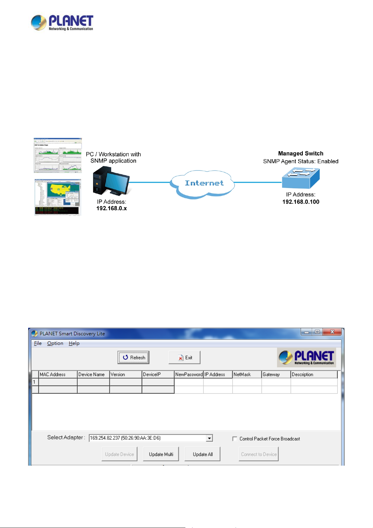
User’s Manual of LRP-822CS/LRP-1622CS
3.5 SNMP-based Network Management
You can use an externa
anager, HP Openview Network Node Management (NNM) or What’s Up Gold. This management method requires the SNMP
M
agent on the switch and the SNMP N
method, in fact, uses two community strings: the get community string and the set community string. If the SNMP Net-work
management Station only knows the set community string, it can read and write to the MIBs. However, if it only knows the get
community string, it can only read MIBs. The default gets and sets community strings for the LRP Managed Switch are public.
l SNMP-based application to configure and manage the LRP Managed Switch, such as SNMP Network
etwork Management Station to use the same community string. This management
Figure 3-1-5 SNMP management
.6 PLANET Smart Discovery Utility
3
For easily listing the LRP Managed Switch in your Ethernet environment, the Planet Smart Discovery Utility from user’s manu
CD-ROM is an ideal solution. The following installation instructions are to guide you to running the P
Utility.
1. Deposit the Planet Smart Discovery Utility in administrator PC.
2. Run this utility as the following screen appears.
lanet Smart Discovery
al
Figure 3-1-6: Planet Smart Discovery Utility Screen
41
Page 42
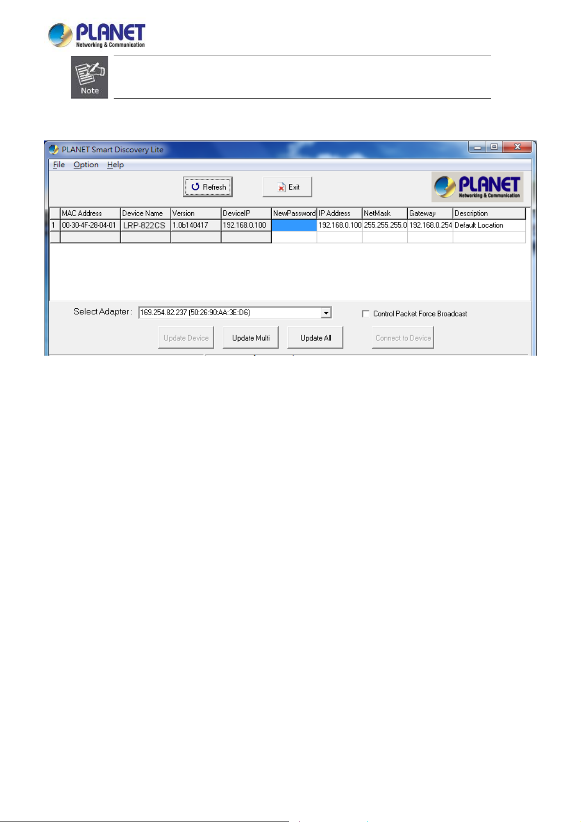
User’s Manual of LRP-822CS/LRP-1622CS
If there are two LAN cards or above in the same
by using the “Select Adapter” tool.
3. Press the “Refresh” button for the currently connected devices in the discovery list as the screen shows below:
administrator PC, choose a different LAN card
Figure 3-1-7: Planet Smart Discovery Utility Screen
1. This utility shows all necessary information from the devices, such as MAC Address, Device Name, firmware version and
Device IP
2. After setup is compl
of the 3 buttons above are shown below:
Update Device: use the current setting on one si
Subnet address. It can also assign new password, IP subnet address and description to the devices.
eted, press the “Update Device”, “Update Multi” or “Update A ll” button to take effect. The meaning
ngle device.
Update Multi: use the current setting on multi-devices.
Update All: use the current setting on whole devices in the list.
The same functions mentioned above also can be found in “Option” tools bar.
3. To click the “Control Packet Force Broadcast” function, it allows you to assign a new setting value to the Web Smart
Switch under a different IP subnet address.
4. Press the “Connect to Device” button and the Web login screen appears in Figure 3-1-4.
5. Press the “Exit” button to shut down the Planet Smart Discovery Utility.
42
Page 43
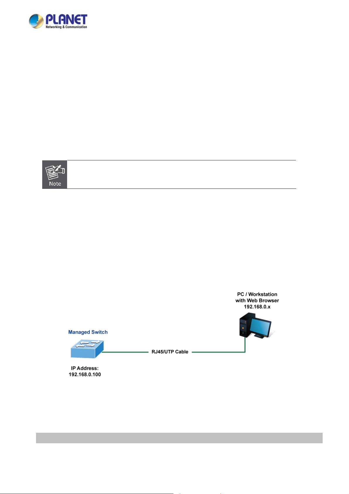
User’s Manual of LRP-822CS/LRP-1622CS
4. WEB CONFIGURATION
This section introduces the configuration and functions of the Web-based management.
About Web-based Management
The LRP Managed Switch offers management features that allow users to manage the LRP Managed Switch from anywhere on
the network through a standard browser such as Microsoft Internet Explorer.
The Web-based Management supports Internet Explorer 8.0. It is based on Java Applets with an aim to reduce network
bandwidth consumption, enhance access speed and present an easy viewing screen.
By default, IE8.0 or later version does not allow Java Applets to open sockets. The user has to
explicitly modify the browser setting to enable Java Applets to use network ports.
The LRP Managed Switch can be configured through an Ethernet connection, making sure the manager PC must be set on the
same IP subnet address as the LRP Managed Switch.
or example, the default IP address of the LRP Managed Switch is 192.168.0.100, then the manager PC should be set at
F
192.168.0.x (where x is a number between 1 and 254, except 100), and the default subnet mask is 255.255.255.0.
If you have changed the default IP address of the LRP Managed Switch to 192.168.1.1 with subnet mask 255.255.255.0 via
console, then the manager PC should be set at 192.168.1.x (where x is a number between 2 and 254) to do the relative
configuration on manager PC.
Figure 4-1-1 Web Management
Logging on the switch
1. Use Internet Explorer 8.0 or above Web browser. Enter the factory-default IP address to access the Web interface. The
factory-default IP address is as follows:
http://192.168.0.100
43
Page 44

User’s Manual of LRP-822CS/LRP-1622CS
2. When the following login screen appears, please enter the default username "admin" with password “admin” (or the
n the main screen of LRP Managed Switch. The login screen username/password you have changed via console) to logi
in Figure 4-1-2 appears.
Figure 4-1-2 Login screen
Default User Name: admin
Default Password: admin
After entering the username and password, the main screen appears as Figure 4-1-3.
Figure 4-1-3 Default Main Page
44
Page 45

User’s Manual of LRP-822CS/LRP-1622CS
Now, you can use the Web management interface to continue the switch management or manage the LRP Managed Switch
by
Web interface. The Switch Menu on the left of the web page lets you access all the commands and statistics the LRP Managed
Switch provides.
It is recommended to use Internet Explore 8.0 or above to access LRP Managed Switch.
The changed IP address takes effect immediately after clicking on the Save button. You need to
use the new IP address to access the Web interface.
For security reason, please change and memorize the new password after this first setup.
Only accept command in lowercase letter under Web interface.
45
Page 46
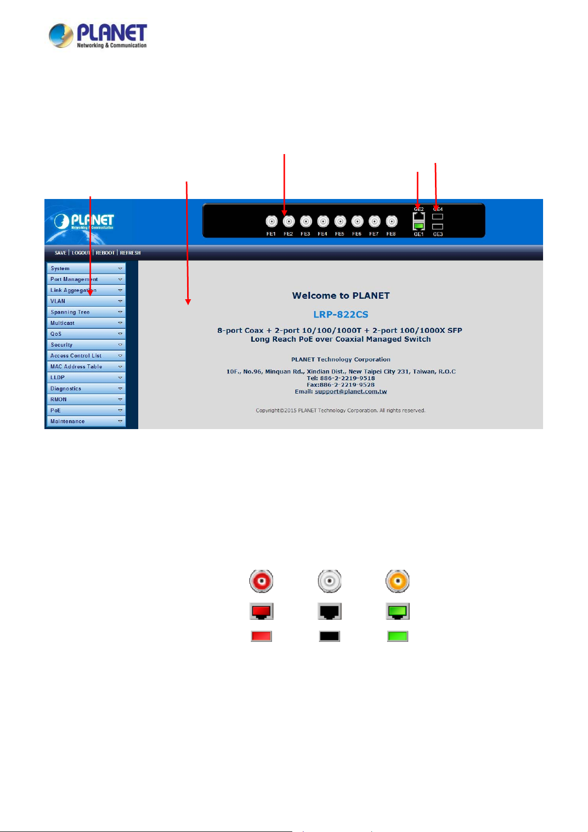
User’s Manual of LRP-822CS/LRP-1622CS
4.1 Main Web Page
The LRP Managed
access the LRP Managed Switch using the Web browser of your choice. This chapter describes how to use the LRP Managed
Switch’
s Web browser interface to configure and manage it.
Main Functions Menu
Switch provides a Web-based browser interface for configuring and managing it. This interface allows you to
Port Link Status
SFP
Main Screen
LRP Port Link Status
Coppe
r Port Link Status
igure 4-1-4 Main Page
F
Panel Display
The Web agent displays an image of the LRP Managed Switch’s ports. The Mode can be set to display different information for
the ports, including Link up or Link down. Clicking on the image of a port opens the Port Statistics page.
The port states are illustrated as follows:
State Disabled Down Link
LRP Ports
RJ45 Ports
SFP Ports
Main Menu
Using the onboard Web agent, you can define system parameters, manage and control the LRP Managed Switch, and all its
ports, or monitor network conditions. Via the Web-Management, the administrator can set up the LRP Managed Switch by
selecting the functions those listed in the Main Function. The screen in Figure 4-1-5 appears.
46
 Loading...