

Page 1

A
Server Load Balancer
LB-8000
Administration Guide
Administration Guide for LB-8000 R2.6.2 Revision.
PLANET Technology Corp.
1
Page 2

A
Trademarks
Copyright PLANET Technology Corp. 2003.
Contents subject to revision without prior notice.
PLANET is a registered trademark of PLANET Technology Corp. All other
trademarks belong to their respective owners.
Disclaimer
PLANET Technology does not warrant that the hardware will work properly in all
environments and applications, and makes no warranty and representation, either
implied or expressed, with respect to the quality, performance, merchantability, or
fitness for a particular purpose.
PLANET has made every effort to ensure that this User’s Manual is accurate; PLANET
disclaims liability for any inaccuracies or omissions that may have occurred.
Information in this User’s Manual is subject to change without notice and does not
represent a commitment on the part of PLANET. PLANET assumes no responsibility
for any inaccuracies that may be contained in this User’s Manual. PLANET makes no
commitment to update or keep current the information in this User’s Manual, and
reserves the right to make improvements to this User’s Manual and/or to the products
described in this User’s Manual, at any time without notice.
If you find information in this manual that is incorrect, misleading, or incomplete, we
would appreciate your comments and suggestions.
FCC Warning
This equipment has been tested and found to comply with the limits for a Class A
digital device, pursuant to Part 15 of the FCC Rules. These limits are designed to
provide reasonable protection against harmful interference when the equipment is
operated in a commercial environment. This equipment generates, uses, and can
radiate radio frequency energy and, if not installed and used in accordance with the
Instruction manual, may cause harmful interference to radio communications.
Operation of this equipment in a residential area is likely to cause harmful interference
in which case the user will be required to correct the interference at his own expense.
CE Mark Warning
This is a Class A product. In a domestic environment, this product may cause radio
interference, in which case the user may be required to take adequate measures.
Revision
PLANET Server Load Balancer Administration Guide
For Model: LB-8000
Part No.: EMA-LB8000
Administration Guide for LB-8000 R2.6.2 Revision.
PLANET Technology Corp.
2
Page 3

A
Table of Content
1. INTRODUCTION................................................................................................................5
1.1. GETTING STARTED.........................................................................................................5
1.2. TERMS USED IN THIS DOCUMENT.....................................................................................6
2. LB-8000 OVERVIEW.........................................................................................................7
3. CONFIGURE THE CLUSTER............................................................................................8
3.1. NAT MODEL..................................................................................................................8
3.1.1. Gateway for realservers.......................................................................................9
3.1.2. How does a virtual server via NAT work?..........................................................10
3.2. DIRECT ROUTING MODEL .............................................................................................13
3.2.1. How does a virtual server via Direct Routing work?..........................................13
3.2.2. The important concept on Direct Routing Model................................................16
3.3. IP TUNNELING MODEL..................................................................................................17
3.3.1. How does a virtual server via IP Tunneling work?.............................................18
3.3.2. The important concept on IP Tunneling Model...................................................20
3.4. HOW TO CONFIGURE A CLUSTER?..................................................................................20
4. SELECT LOAD DISTRIBUTION SCHEDULE.................................................................22
4.1. ROUND-ROBIN SCHEDULE............................................................................................22
4.2. WEIGHTED ROUND-ROBIN SCHEDULE...........................................................................23
4.3. LEAST-CONNECTION SCHEDULE...................................................................................23
4.4. WEIGHTED LEAST-CONNECTION SCHEDULE..................................................................24
4.5. HOW TO CONFIGURE THE SCHEDULE OF A CLUSTER?......................................................25
4.6. MONITOR THE LOAD DISTRIBUTION OF LB-8000.............................................................26
5. MANAGER FAILOVER WITH HEARTBEAT...................................................................29
5.1. HEARTBEAT PROTOCOL................................................................................................29
5.2. STATEFUL FAILOVER.....................................................................................................31
5.3. CONFIGURE THE HEARTBEAT AND ROLE OF LB-8000......................................................32
6. HEALTH CHECK AND MONITOR OF REAL SERVER..................................................33
6.1. NO HEALTH CHECK......................................................................................................35
6.2. L3 HEALTH CHECK (ICMP CHECK)...............................................................................35
6.3. L4 HEALTH CHECK (PORT CHECK)...............................................................................35
6.4. L7 HEALTH CHECK (CONTENT CHECK).........................................................................37
6.5. HOW TO CONFIGURE THE HEALTH CHECK?.....................................................................39
7. PERSISTENCE CONNECTION.......................................................................................40
7.1. BROWSER / DATABASE / TCP/IP PERSISTENCE.............................................................40
7.2. LB-8000 PERSISTENCE................................................................................................41
7.3. HOW TO CONFIGURE THE PERSISTENCE?......................................................................42
8. ARP PROBLEM...............................................................................................................43
8.1. HIDDEN INTERFACE ON LINUX BASED REALSERVER ........................................................44
9. LOG MANAGEMENT.......................................................................................................46
9.1. LOG MESSAGES ...........................................................................................................46
Administration Guide for LB-8000 R2.6.2 Revision.
PLANET Technology Corp.
3
Page 4

A
9.2. MAIL ALERT .................................................................................................................47
10. SNMP SUPPORT..........................................................................................................48
10.1. MIB.........................................................................................................................48
10.2. SNMP MONITOR......................................................................................................50
11. MANAGE SERVER CONTENT....................................................................................53
11.1. HOW TO CONNECT TO REALSERVER?.........................................................................53
11.2. STATIC ROUTE .........................................................................................................54
11.3. INBOUND / OUTBOUND LIMITATION.............................................................................55
11.4. NAT ROUTER ..........................................................................................................55
Administration Guide for LB-8000 R2.6.2 Revision.
PLANET Technology Corp.
4
Page 5

A
1. Introduction
1.1. Getting Started
Before you start to install LB-8000 into your network environment, we suggest you browse the
Quick Installation Guide for LB-8000 first to prepare the basic necessary environment. When
you are ready to install LB-8000, you can refer to the following documentation to make your
installation is successful.
l Quick Installation Guide for LB-8000
This guide provides the quick procedures to setup a simple cluster system of NAT model.
It also includes the procedures to setup the redundancy of LB-8000 (The primary
manager and backup manager).
l User Guide for LB-8000
This guide provides the user operating instructions on each screen of web based
management system and each command of CLI (command line interface) of LB-8000.
l Administration Guide for LB-8000
This guide provides the administrative information on the technology of LB-8000. It also
provides the setup procedures that are not introduced in Quick Installation Guide for
LB-8000, such as different cluster models.
Administration Guide for LB-8000 R2.6.2 Revision.
PLANET Technology Corp.
5
Page 6

A
1.2. Terms used in this document
In this document, we use the following terms to identify the roles of machine:
l LB-8000: the cluster manager and a director for forwarding the requests to realservers.
l Client: the user applications that connects to the LB-8000.
l Realservers: the servers that provide the services. The realservers handle the requests
from the clients.
We also use some short terms to identify the name of IPs:
Client IP = CIP
Virtual IP = VIP (the IP of virtual server)
Director IP = DIP (the IP on the LB-8000 in the realserver's network)
Realserver IP = RIP (and RIP1, RIP2...) (the IP on the realserver)
Administration Guide for LB-8000 R2.6.2 Revision.
PLANET Technology Corp.
6
Page 7

A
2. LB-8000 Overview
The LB-8000 is a load balancer for a cluster of servers that appears to be one server to an
outside client. This apparent single server is called here a "virtual server". The realservers
are under the control of the LB-8000, which runs a Linux kernel patched to include the Linux
ipvs code.
When a client requests a new connection to a virtual server (e.g., a web cluster), the LB-8000
will choose a realserver for the client. Since then, all packets from the client will go through
the LB-8000 to that particular realserver. The association between the client and the
realserver will last for only the life span of the tcp connection (or udp exchange). For the next
tcp connection, the LB-8000 will choose a new realserver (which may or may not be the same
as the first realserver). (Please refer to Chapter 3 Configure the Cluster for detail information)
Administration Guide for LB-8000 R2.6.2 Revision.
PLANET Technology Corp.
7
Page 8

A
3. Configure the cluster
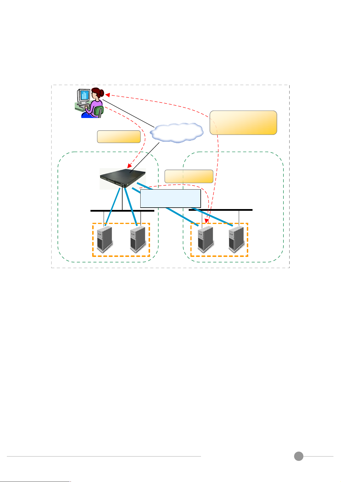
Manager
LB-8000 provides three types of cluster. They are NAT model, Direct Routing model and IP
Tunneling model.
Here is a basic network configuration of LB-8000 as depicted in Fig. 1.
Internet
Primary
Web Cluster
3.1. NAT Model
Heartbeat
Streaming
Router
Backup
Non-cluster
Fig. 1 LB-8000 network topology
Firewal
Web GUI / CLI
System
In NAT model, the destination IP address of incoming packets are rewritten by the LB-8000 to
be the IP address of one of the realservers and then forwarded to the realserver. Then, the
replies from the realserver are sent to the LB-8000 and each source IP address is rewritten to
be the original IP address of client.
Unlike the other two methods of forwarding used in LB-8000 (DR model and IP Tunneling
model), the realserver only needs a functional TCP/IP stack. The realserver can have any
kind of operating system and almost no modifications are required to the configuration of the
realservers (except setting their default gateway).
Administration Guide for LB-8000 R2.6.2 Revision.
PLANET Technology Corp.
8
Page 9

A
3.1.1. Gateway for realservers
For NAT model to work
• All packets from the realservers to the client must go through the LB-8000.
So, you must set the default gateway of realserver to LB-8000. Forgetting to set this up is the
most common cause of failure when setting up a NAT model.
When you are configuring the IP address of network 2 (eth1) of LB-8000, the gateway of
network 2 is the virtual gateway for realservers. So, you should set the default gateway of
realserver to this gateway IP address.
In tradition, the default gateway of the realserver would be the router to the Internet and the
packet (RIPàCIP) would be sent directly to the client. In a LB-8000 NAT model, the default
gateway of the realservers must be the LB-8000. The LB-8000 masquerades the packet from
the realserver (rewrites it to VIPàCIP) and the client receives a rewritten packet with the
expected source IP of the VIP.
The packet must be routed via the LB-8000; there must be no other path to the client. A packet
arriving at the client directly from the realserver will not be seen as a reply to the client's request
and the connection will hang.
Administration Guide for LB-8000 R2.6.2 Revision.
PLANET Technology Corp.
9
Page 10

A
3.1.2. How does a virtual server via NAT work?
Primary
Backup
the request
. Rewriting
replies
rewriting packets
First consider the following figure (Fig.2).
4
LB-8000
3. Processing
5. Replies
Internet
1. Requests
Router
Firewall
2. Scheduling &
LB-8000
Fig. 2 NAT configuration
When a user requests the service provided by the server cluster, the request packet destined
for virtual IP address (the external IP address for the load balancer) arrives at the LB-8000.
The LB-8000 examines the packet's destination address and port number. If they are
matched for a virtual server service according to the virtual server rule table, a real server is
chosen from the cluster by a scheduling algorithm, and the connection is added into the hash
table which records the established connection. Then, the destination address and the port
of the packet are rewritten to those of the chosen server, and the packet is forwarded to the
server. When the incoming packet belongs to this connection and the chosen server can be
found in the hash table, the packet will be rewritten and forwarded to the chosen server.
When the reply packets come back, the load balancer rewrites the source address and port of
the packets to those of the virtual service. After the connection is terminated or timeout, the
connection record will be removed from the hash table.
Administration Guide for LB-8000 R2.6.2 Revision.
PLANET Technology Corp.
10
Page 11

A
The following diagram shows the handshaking process of HTTP protocol:
Fig. 3 HTTP handshaking protocol with LB-8000 NAT configuration
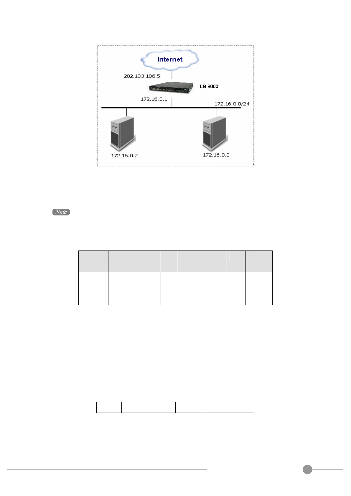
Here is an example to make it clear. In the example, computers are configured as follows.
Please notes that the IP address of 172.16.0.1 is the virtual gateway IP of network 2 interface
(eth1) of LB-8000 and realservers)
Administration Guide for LB-8000 R2.6.2 Revision.
PLANET Technology Corp.
11
Page 12
A
Fig. 4 LB-8000 and 2 Realservers configuration
Realservers can run any OS that supports TCP/IP; the default gateway of real servers must be
the LB-8000 (172.16.0.1 in this example).
The following table illustrates the rules specified in the LB-8000 with virtual server support.
Protocol Virtual IP
Address
Port Real IP
Address
Port Weight
172.16.0.2 80 1 HTTP 202.103.106.5 80
172.16.0.3 8000 2
FTP 202.103.106.5 21 172.16.0.3 21 1
All traffic destined for IP address 202.103.106.5 Port 80 is load-balanced over real IP address
172.16.0.2 Port 80 and 172.16.0.3 Port 8000. Traffic destined for IP address 202.103.106.5
Port 21 is port-forwarded to real IP address 172.16.0.3 Port 21.
Packet rewriting works as follows.
(1) The incoming packet for web service would have source and destination addresses
as:
Source 202.100.1.2:3456 DEST 202.103.106.5:80
(2) The LB-8000 will choose a real server, e.g. 172.16.0.3:8000. The packet would be
rewritten and forwarded to the server as:
Administration Guide for LB-8000 R2.6.2 Revision.
PLANET Technology Corp.
12
Page 13

A
Source 202.100.1.2:3456 DEST 172.16.0.3:8000
(3) Replies get back to the load balancer as:
Source 172.16.0.3:8000 DEST 202.100.1.2:3456
(4) The packets would be written back to the virtual server address and returned to the
client as:
Source 202.103.106.5:80 DEST 202.100.1.2:3456
3.2. Direct Routing Model
In Direct Routing model, real servers and the LB-8000 share the virtual IP address. The
LB-8000 has a network interface configured with the virtual IP address too, which is used to
accept request packets, and it directly route the packets to the chosen servers. All the real
servers have their non-arp alias interface configured with the virtual IP address (e.g., a
loopback interface), so that the real servers can process the packets locally. The LB-8000
and the real servers must have one of their network interfaces physically linked by a
HUB/Switch.
3.2.1. How does a virtual server via Direct Routing work?
The architecture of virtual server via direct routing is illustrated as follows:
Administration Guide for LB-8000 R2.6.2 Revision.
PLANET Technology Corp.
13
Page 14

A
Internet
LB-8000
LB-8000
1. Requests
3. Replies going
to the user
Primary
Router
Firewall
2. Scheduling
Fig. 5 Direct Routing configuration
When a user requests a virtual service provided by the LB-8000, the packet destined for virtual
IP address (the IP address for the virtual server) was send to the LB-8000 from the user. The
LB-8000 examines the packet's destination address and port. If they are matched for a virtual
Backup
service, a real server is chosen from the cluster by a scheduling algorithm, and the connection
is added into the hash table that records connections. Then, the LB-8000 forwards the
packet to the chosen server. When the incoming packet belongs to this connection and the
chosen server can be found in the hash table, the packet will be again routed to the server.
When the server receives the forwarded packet, the server finds that the packet is for the
address on its alias interface or for a local socket, so it processes the request and returns the
result directly to the user finally. After a connection is terminated or timeout, the connection
record will be removed from the hash table.
Administration Guide for LB-8000 R2.6.2 Revision.
PLANET Technology Corp.
14
Page 15

A
The direct routing workflow is illustrated in the following steps:
Protocol Virtual IP
Address
Port Real IP
Address
Port Weight
192.168.1.6 80 2 HTTP 192.168.1.110 80
192.168.1.7 80 1
(1) There is http request from client which IP address is 192.168.2.100
Source Destination Data
192.168.2.100:3456 192.168.1.110:80 ******
(2) Then LB-8000 will choose a realserver from the schedule and create a link-layer packet.
In this packet, the original IP address of source and destination will be the data.
Source MAC Destination MAC Data (IP datagram)
00:00:00:00:00:66 00:00:00:00:00:88 source=192.168.2.100:3456,
dest=192.168.1.110:80,
data=******
(3) When realserver receive this packet, and then recovers it to IP datagram.
Source Destination Data
192.168.2.100:3456 192.168.1.110:80 ******
(4) Now, realserver looks up the routing table, find the VIP (192.168.1.110) is its local IP
address. So the realserver processes this request locally and generates the replies.
Source Destination Data
192.168.1.110:80 192.168.2.100:3456 ******
(5) Then this reply packet leaves realservers via its default gateway, not via LB-8000.
The LB-8000 simply changes the MAC address of the data frame to that of the chosen server
and retransmits it on the LAN. This is the reason that the LB-8000 and each server must be
directly connected to one another by a single uninterrupted segment of a LAN.
And the following picture shows the handshake process of HTTP protocol:
Administration Guide for LB-8000 R2.6.2 Revision.
PLANET Technology Corp.
15
Page 16

A
Fig. 6 HTTP handshaking protocol with LB-8000 Direct Routing configuration
3.2.2. The important concept on Direct Routing Model
The setup and testing of DR model are the same as IP Tunneling model except that all
machines within the DR model (i.e., the LB-8000 and realservers) must be able to ARP each
other. This means that they have to be on the same network without any forwarding devices
between them. That is to say they are using the same piece of transport layer hardware
("wire"), e.g., RJ-45. There can be hub(s) or switch(es) in this mix. Communication within the
LB-8000 is by link-layer, using MAC addresses rather than IP's. All machines in the cluster of
LB-8000 have the VIP, only the VIP on the LB-8000 replies to ARP requests, the VIP on the
realservers must be on a non-arp device (e.g., lo:0, dummy).
The restrictions for DR model are:
• The client must be able to connect to the VIP on the LB-8000.
• Realservers and the LB-8000 must be physically wired together (they must be able to
ARP each other) as packets are sent by link-layer from the LB-8000 to the realservers.
Administration Guide for LB-8000 R2.6.2 Revision.
PLANET Technology Corp.
16
Page 17

A
• The route from the realservers to the client cannot go through the LB-8000, i.e. the
LB-8000 cannot be the default gateway for the realservers. (Note: the client does not
need to connect to the realservers for the LB-8000 to function. The realservers could
be behind a firewall, but the realservers must be able to send packets to the client).
The return packets, from the realservers to the client, go directly from the realservers
to the client and do not go back through the LB-8000. For high throughput, each
realserver can have its own router/connection to the client/Internet and return packets
need not go through the router attached with the LB-8000.
In order to provide the graceful service, the real servers should be configured to listen
the VIP only.
Normally for DR model, the client is on a different network to the LB-8000/server(s), and each
realserver has its own route to the outside world. In the simple test case below, all machines
are on the 192.168.1.0 network without routers, and the return packets would be sent directly
to the client via the network device on 192.168.1.0 (presumably).
3.3. IP Tunneling Model
IP tunneling (IP encapsulation) is a technique to encapsulate IP datagram within IP datagrams,
which allows datagrams destined for one IP address to be wrapped and redirected to another
IP address. IP encapsulation is now commonly used in Extranet, Mobile-IP, IP-Multicast,
tunneled host or network.
First, let's look at the figure of virtual server via IP tunneling. The most different thing of virtual
server between IP tunneling model and NAT model is how LB-8000 sends the requests to real
servers.
Administration Guide for LB-8000 R2.6.2 Revision.
PLANET Technology Corp.
17
Page 18
A
3.3.1. How does a virtual server via IP Tunneling work?
Inte
rnet
Subnet
A
Subnet
B
Tunnel
Cluster
A Cluster
B
2. Scheduling
the user directly
The architecture of virtual server via IP Tunneling is illustrated as follows:
3. Replies going to
(192.168.5.xxx)
(Encapsulation)
Fig. 7 LB-8000 IP Tunneling configuration
When a user requests a virtual service provided by the server cluster, a packet destined for
virtual IP address (the IP address for the virtual server) is received by LB-8000. The LB-8000
examines the packet's destination address and port. If they are matched for the virtual
(192.168.10.xxx)
service, a real server is chosen from the cluster according to a connection scheduling
algorithm, and the connection is added into the hash table which records connections. Then,
the LB-8000 encapsulates the packet within an IP datagram and forwards it to the chosen
server. When an incoming packet belongs to this connection and the chosen server can be
found in the hash table, the packet will be again encapsulated and forwarded to that server.
When the server receives the encapsulated packet, it decapsulates the packet and processes
the request, finally return the result directly to the user according to its own routing table.
After a connection is terminated or timeout, the connection record will be removed from the
hash table.
The workflow is illustrated in the following steps:
Administration Guide for LB-8000 R2.6.2 Revision.
PLANET Technology Corp.
18
Page 19

A
Protocol Virtual IP
Address
Port Real IP
Address
Port Weight
192.168.23.6 80 2 HTTP 192.168.1.110 80
192.168.23.7 80 1
The IP address of LB-8000 is 192.168.1.88.
(1) There is http request from client which IP address is 192.168.2.100
Source Destination Data
192.168.2.100:3456 192.168.1.110:80 ******
(2) Then LB-8000 will choose a realserver from the schedule and encapsulate into IPIP
packet. In this packet, the original IP address of source and destination will be the data.
Source Destination Data (IP datagram)
192.168.1.88 192.168.23.6 source=192.168.2.100:3456,
dest=192.168.1.110:80,
data=******
(3) When realserver receive this packet, and then recovers it to IP datagram.
Source Destination Data
192.168.2.100:3456 192.168.1.110:80 ******
(4) Now, realserver looks up the routing table, find the VIP (192.168.1.110) is its local IP
address. So the realserver processes this request locally and generates the replies.
Source Destination Data
192.168.1.110:80 192.168.2.100:3456 ******
(5) Then this reply packet leaves realservers via its default gateway, not via LB-8000.
Note that real servers can have any real IP address in any network, and they can be
geographically distributed, but they must support IP encapsulation protocol. Their tunnel
devices are all configured up so that the systems can decapsulate the received encapsulation
packets properly, and the <Virtual IP Address> must be configured on non-arp devices or any
Administration Guide for LB-8000 R2.6.2 Revision.
PLANET Technology Corp.
19
Page 20

A
alias of non-arp devices, or the system can be configured to redirect packets for <Virtual IP
Address> to a local socket.
Finally, when an encapsulated packet arrives, the real server decapsulates it and finds that the
packet is destined for <Virtual IP Address>, it says, "Oh, it is for me, so I do it.", it processes
the request and returns the result directly to the user.
3.3.2. The important concept on IP Tunneling Model
IP Tunneling model is based on DR model and has the same high scalability/throughput of DR
model.
IP Tunneling model can be used with realservers that can tunnel (==IPIP encapsulation). The
LB-8000 encapsulates the request packet inside an IPIP packet before sending it to the
realserver. The realserver must be able to decapsulate the IPIP packet (currently Linux only).
(With DR model, the realservers can have almost any OS.)
Unlike DR model, with IP Tunneling model, the realservers can be on a network different from
the LB-8000, and can be on separate networks. Thus the realservers could be in different
countries (e.g., a set of ftp mirror sites for a project). If this is the case the realservers will
generate reply packets with VIPàCIP. And the routers for the realservers will have to be
programmed to accept outgoing packets with source IP =VIP. Routers normally drop these
packets as an anti-spoofing measure.
If the realservers are on the same network as the LB-8000, then DR model and IP Tunneling
model are the same in performance and ease of setup.
3.4. How to configure a cluster?
You can configure a cluster by click Configuration in the main menu, and then click Virtual
Host Setup in the sub-menu to add, modify or delete a cluster. When you configure the first
cluster, you should select the cluster type you want.
Administration Guide for LB-8000 R2.6.2 Revision.
PLANET Technology Corp.
20
Page 21

A
Fig. 8 LB-8000 Network Configuration GUI
There are two concepts:
l All clusters should be the same model. For example, you cannot create a cluster as
NAT model and another cluster as Direct Routing model.
l If you change any one of the cluster type in the existing clusters. Then all clusters will
be changed to the same cluster type. For example, if you change the cluster type of
one of the existing clusters from NAT model to Direct Routing model, all clusters will be
changed to Direct Routing model.
You also can configure the cluster by issuing “cluster” and “rs” command from CLI. Please
refer to Chapter 4 CLI Configuration on User’s Manual of LB-8000 for detail description.
Administration Guide for LB-8000 R2.6.2 Revision.
PLANET Technology Corp.
21
Page 22

A
4. Select Load Distribution Schedule
When receiving a request from a client, the LB-8000 assigns a realserver to handle the request
based on a "schedule". The available schedules are:
l Round robin (rr), weighted round robin (wrr) - new connections are assigned to each
realserver in turn.
l Least connection (lc), weighted least connection (wlc) - new connections are assigned to
the realserver with the least number of connections. The assigned real server might not
be the least busy one but it’s the direction we try to approach. The following sections
show the detail description on each schedule.
4.1. Round-Robin Schedule
The round-robin scheduling algorithm sends each incoming request to the next server on its
list. In a cluster with three real servers
(servers A, B and C), the first request
would go to server A, the second request
would go to server B, the third request
would go to server C, and the forth
request would go to server A again. It
treats all real servers equally regardless
of the number of incoming connections or
response time for each server.
Fig. 9 LB-8000 Round Robin scheduling
Administration Guide for LB-8000 R2.6.2 Revision.
PLANET Technology Corp.
22
Page 23

A
4.2. Weighted Round-Robin Schedule
The weighted round-robin scheduling is designed to better handle servers with different
processing capacities. Each server can be
assigned a weight, an integer value that
indicates the processing capacity. The
default weight is 1 and can be set up to 99.
For example, the real servers, A, B and C,
have the weights, 4, 3, 2 respectively, a
good scheduling sequence will be
AABABCABC in a scheduling period. In
the implementation of the weighted
round-robin scheduling, a scheduling
sequence will be generated according to
the server weights after the rules of Virtual
Server are modified. The network
connections are directed to the different
Fig. 10 Weighted RR scheduling
real servers based on the scheduling
sequence in a round-robin manner.
The weighted round-robin scheduling is better than the round-robin scheduling, when the
processing capacity of real servers are different. However, it may lead to dynamic load
imbalance among the real servers if the load of the requests is varying highly. In short, there is
the possibility that a majority of requests requiring large responses may be directed to the
same real server.
Actually, the round-robin scheduling is a special instance of the weighted round-robin
scheduling, in which all the weights are equal.
4.3. Least-Connection Schedule
The least-connection scheduling algorithm directs network connections to the server with the
least number of established connections. This is one of the dynamic scheduling algorithms;
because it needs to count live connections for each server. For a Virtual Server that is
managing a collection of servers with similar performance, least-connection scheduling is good
Administration Guide for LB-8000 R2.6.2 Revision.
PLANET Technology Corp.
23
Page 24

A
to smooth distribution when the load of requests vary a lot. Virtual Server will direct requests to
Fig. 11
Least
-
Connection scheduling
Weighted LC scheduling
the real server with the fewest active connections.
At a first glance it might seem that
least-connection scheduling can also
perform well even when there are servers
of various processing capacities, because
the faster server will get more network
connections. But there is a potential issue
for this algorithm. That is TCP’s
TIME_WAIT state. The TCP's
TIME_WAIT is usually 2 minutes, during
this 2 minutes a busy web site often
receives thousands of connections, for
example, the server A is twice as powerful
as the server B, the server A is processing
thousands of requests and keeping them
in the TCP's TIME_WAIT state, but server
B is crawling to get its thousands of connections finished. Before doing the configuration, the
administrator needs to consider all network situations.
4.4. Weighted Least-Connection Schedule
The weighted least-connection scheduling is
a superset of the least-connection
scheduling, in which you can assign a
performance weight to each real server. The
servers with a higher weight value will
receive a larger percentage of live
connections at any time. The Virtual Server
Administrator can assign a weight to each
real server, and network connections are
scheduled to each server in which the
percentage of the current number of live
connections for each server is a ratio to its
weight. The default weight is one.
Fig. 12
Administration Guide for LB-8000 R2.6.2 Revision.
PLANET Technology Corp.
24
Page 25

A
The weighted least-connections scheduling works as follows:
Supposing there is n real servers, each server i has weight Wi (i=1,..,n), and alive connections
Ci (i=1,..,n), ALL_CONNECTIONS is the sum of Ci (i=1,..,n), the next network connection will
be directed to the server j, in which
(Cj/ALL_CONNECTIONS)/Wj = min { (Ci/ALL_CONNECTIONS)/Wi } (i=1,..,n)
Since the ALL_CONNECTIONS is a constant in this lookup, there is no need to divide Ci by
ALL_CONNECTIONS, it can be optimized as
Cj/Wj = min { Ci/Wi } (i=1,..,n)
4.5. How to configure the schedule of a cluster?
When you create a new cluster, you can configure the schedule of this cluster. And you also
can change the schedule of an existing cluster at any time. Here is the screen where you can
configure the schedule.
Fig. 13 Configuring the scheduling
Administration Guide for LB-8000 R2.6.2 Revision.
PLANET Technology Corp.
25
Page 26

A
4.6. Monitor the load distribution of LB-8000
You can monitor the load distribution from the web management system. As the following
screen shows:
Fig. 14 LB-8000 Connections
Or you can monitor the load distribution by issuing “load” command from CLI. Here is the
example:
LB8000> load
Load Distribution
Virtual Host: WWW1 IP Address: 211.75.31.212 Port: 80
Real Server Port Weight Connections Distribution
=====================================================================
192.168.3.3 www 1 50 50.00%
192.168.3.4 www 1 50 50.00%
LB8000>
The way that LB-8000 counts current connections:
Current connections # means how many connections are currently connected to a realserver
and can be found from LB-8000 GUI at PERFORMANCE > LOAD DISTRIBUTION. The way
LB-8000 counts connections is to start from point 2, when the SYN packet from the client
arriving LB-8000, to point 24, when two-minute timeout passes after point 20. Please refer to
Fig. 15.
Administration Guide for LB-8000 R2.6.2 Revision.
PLANET Technology Corp.
26
Page 27

A
Fig. 15 Connections
And the bar of load distribution is shown by percentage. The percentage is computed by the
current connection # divided by the total connection # of cluster. As the above screen, the
total connection # of cluster is 1 + 1 = 2. So the percentages of each realserver are 50%,
50%.
Please note that this number depicts the connections # kept in the connection table of LB-8000
and may not be able to truly reflect the state of the real server. Namely, the count may still stay
even after the TCP state of the realserver turns to CLOSED (point 21).
Administration Guide for LB-8000 R2.6.2 Revision.
PLANET Technology Corp.
27
Page 28

A
For example, system admin will not see the current connections # changed immediately after
some clients finish downloading a file from one real server. This is not because of the error of
the counter but because LB-8000 will not end the count until that connection really disappears
from its connection table (point 24).
Here are the default timeout values of each state:
l CLOSE state: 10 seconds
l CLOSE_WAIT state: 60 seconds
l ESTABLISHED state: 900 seconds (adjustable)
l FIN_WAIT state: 120 seconds (adjustable)
l LAST_ACK state: 30 seconds
l SYN_ACK state: 120 seconds
l SYN_RECEIVED state: 60 seconds
l SYN_SENT state: 120 seconds
l TIME_WAIT state: 120 seconds
l UDP packet: 300 seconds (adjustable)
l ICMP packet: 60 seconds
You can change the timeout value by issuing “ctimer” command from CLI. This command
always takes 3 parameters, representing the timeout values (in seconds) for TCP sessions
(ESTABLISHED state), TCP sessions after receiving a FIN packet (FIN_WAIT state), and
UDP packets, respectively. A timeout value 0 means that the current timeout value of the
corresponding entry is preserved.
Administration Guide for LB-8000 R2.6.2 Revision.
PLANET Technology Corp.
28
Page 29

A
5. Manager Failover with Heartbeat
5.1. Heartbeat Protocol
In order to create a High Availability service, LB-8000 uses heartbeat protocol to create a
failover protection between primary and backup manager. This structure is an active-standby
model. That means, the primary LB-8000 is the active manager, and backup LB-8000 is the
standby waiting to take over the jobs of primary when primary fails.
The heartbeat protocol uses UDP port 694 to send a UDP message from network 1 interface to
other LB-8000. The following figure shows the procedures of failover from primary to backup:
Primary Manager Backup Manager
Heartbeat
Heartbeat
Receive
heartbeat message
of primary
NO
Can
receive heartbeat
of primary before
timeout
NO
Create alias IP of
cluster
Start health check
monitor
YES
YES
Start Cluster Service
Fig. 16 The failover from primary to backup
Administration Guide for LB-8000 R2.6.2 Revision.
PLANET Technology Corp.
29
Page 30

A
The LB-8000 manager will send heartbeat message according to the value of keepalive setting
(The keepalive setting is used on CLI, it is the same as “How many seconds to send a
heartbeat?” on GUI). If backup manager can not receive the heartbeat after the timeout value
(the timeout value is 3 times of the value of keepalive, for example, if the value of keepalive is
3 seconds, the timeout value will be 3 x 3 = 9 seconds). Then backup manager will take over
to provide the service. But if backup manager can receive the heartbeat message from
primary manager before the timeout value, the backup manager won’t take over.
The procedures of service up on backup manager are:
(1) Create the alias IPs for virtual server and virtual gateway (if your virtual server is NAT
model)
(2) Start the service of health check.
(3) Start the cluster service.
Here is the time for backup manager to take over:
The value of keepalive could be 1 to 9 seconds. So, the time for backup manager to take
over will be minimize to 3 seconds and maximize to 36 seconds.
When primary manager is alive again, it will synchronize the connection table, log files and
configuration files from backup manager first. Then after 10 seconds, primary manager will
start the heartbeat protocol and take over the service from backup manager. So, before the
primary manager to take over from backup manager, the primary manager will need more than
10 seconds to synchronize. If the log files are bigger, the primary manager need more time to
synchronize. But, the time for primary manager to take over from backup manager will less
than 1 second.
Administration Guide for LB-8000 R2.6.2 Revision.
PLANET Technology Corp.
30
Page 31

A
In LB-8000, the heartbeat protocol will send the heartbeat message via network 1 interface. If
there is any fail on network cable or interface on primary manager, the backup manager will
start to take over the cluster service, because the backup manager can’t receive the heartbeat
message from primary manager.
5.2. Stateful Failover
In order to make LB-8000 failover transparent to client applications, the primary manager
needs to synchronize its state information (e.g., connection information) to the backup
manager. When the backup manager takes over the service after the primary fails, the backup
manager will have the state of most connections, so that almost all connections can continue
to access the service through the backup manager.
LB-8000 uses UDP multicast to propagate the creation/changes of connections from the
primary manager to backup manager. The primary manager saves the changes of connections
in the sync queue. A syncmaster daemon is started inside the kernel on the primary manager,
and it multicasts connection state in the queue when a new TCP connection is established.. A
syncbackup daemon is started inside the kernel on backup manager, and it accepts multicast
messages to create/change corresponding connections.
The syncmaster multicasts messages to the backup manager in the following format:
0 1 2 3
0 1 2 3 4 5 6 7 8 9 0 1 2 3 4 5 6 7 8 9 0 1 2 3 4 5 6 7 8 9 0 1
+-+-+-+-+-+-+-+-+-+-+-+-+-+-+-+-+-+-+-+-+-+-+-+-+-+-+-+-+-+-+-+-+
| Count Conns | Reserved | Size |
+-+-+-+-+-+-+-+-+-+-+-+-+-+-+-+-+-+-+-+-+-+-+-+-+-+-+-+-+-+-+-+-+
| LB-8000 Sync Connection (1) |
+-+-+-+-+-+-+-+-+-+-+-+-+-+-+-+-+-+-+-+-+-+-+-+-+-+-+-+-+-+-+-+-+
| . |
| . |
| . |
+-+-+-+-+-+-+-+-+-+-+-+-+-+-+-+-+-+-+-+-+-+-+-+-+-+-+-+-+-+-+-+-+
| LB-8000 Sync Connection (n) |
+-+-+-+-+-+-+-+-+-+-+-+-+-+-+-+-+-+-+-+-+-+-+-+-+-+-+-+-+-+-+-+-+
And, the information of each connection is:
<Protocol, CIP:CPort, VIP:VPort, RIP:RPort, Flags, State>
Administration Guide for LB-8000 R2.6.2 Revision.
PLANET Technology Corp.
31
Page 32

A
5.3. Configure the heartbeat and role of LB-8000
The default time interval of heartbeat (value of keepalive) is one second. And if a manager
can’t receive a heartbeat message after the timeout value (three times of the value of
keepalive), the manager will send an alert. You also can encrypt the heartbeat message by
issuing a specific string.
Before you configure the heartbeat, it is better for you to configure the role of manager. If you
have two LB-8000s, you can configure one LB-8000 as primary manager and the other is
backup manager. When you configure the role of LB-8000, you should configure the host
name and the domain name of LB-8000. A good host name will be understood easily,
especially when you receive a mail alert from the manager.
Currently, the synchronization between two managers is bi-direction. They will synchronize
the log files and configuration files according to the time of last modification. So, you can
modify any configuration from primary manager or backup manager. They will synchronize
with the newest configuration files.
The first time of synchronization will synchronize the time of primary manager to backup
manager. And then, primary manager will synchronize the time to backup manager at the
midnight everyday. In this way, LB-8000 can ensure to synchronize with newest files which
are located on primary manager or backup manager.
Administration Guide for LB-8000 R2.6.2 Revision.
PLANET Technology Corp.
32
Page 33

A
6. Health Check and Monitor of Real Server
In order to provide High Availability service, LB-8000 will check the health of realservers and
the service that realservers provide. If you create a virtual server for HTTP or HTTPS service,
LB-8000 also provides the way to check the content of web servers.
If LB-8000 finds a realserver that can’t provide the required service, LB-8000 will remove this
realserver from the forwarding table. Then there will be no requests to be forwarded to this
realserver.
The check interval is the same as heartbeat interval, and the default value is one
second. That is to say LB-8000 will do the check every second.
LB-8000 provides a module called “LB-8000 Director Daemon” to control the load balancer,
system monitor, and health check. Besides, it mail alert and send SNMP trap when some thing
wrong. In the new architecture, LB-8000 Director Daemon will fork up to 10 sub daemons,
and averaged all real servers into several groups. Each sub daemon will check a group of
real servers and then tell the LB-8000 Director Daemon about the status of each real server in
the group. Sub daemon checks a real server at a time. LB-8000 Director Daemon checks all
sub daemons at a time. The default number of sub daemons is ten, and it can be changed
from the GUI or CLI. The health check interval is the same with heartbeat. So, the LB-8000
Director Daemon can avoided sending needless checks to real servers and shortens the time
of failover.
Real Server 1
Real Server 2
Real Server 3
Real Server 4
Real Server 5
Real Server 6
GUI
LB
LB-8000
LB-8000
Director Daemon
LB D
Sub Daemon
1
2
m
checks
checks
Real Server n-2
Real Server n-1
checks
Real Server n
Administration Guide for LB-8000 R2.6.2 Revision.
PLANET Technology Corp.
33
Page 34

A
Here is the time for server failure to take effective:
And here is the time for server recovery to take effective:
LB-8000 provides 5 level of health check, includes:
n No health check
n L2 health check (ARP check)
n L3 health check (ICMP check)
n L4 health check (port check)
n L7 health check (content check)
When a real server is down, the sub daemon will only send ICMP check to detect the
status of the real server. It will not send any content check or port check when the
real server is down.
The following sections will describe these methods of health checking.
Administration Guide for LB-8000 R2.6.2 Revision.
PLANET Technology Corp.
34
Page 35

A
6.1. No Health Check
If we use the “none” (don’t check), LB-8000 will not send any packet to check the
health of realservers.
6.2. L3 Health Check (ICMP Check)
LB-8000 uses the ICMP protocol, the “Ping” function, to monitor the realserver. If LB-8000
can’t receive the echo message returned from a realserver after a configured timeout, LB-8000
will generate an alarm message that will be sent to the pre-set email address(s).
But LB-8000 just monitors the realserver is alive or not, it won’t remove the realserver from the
forwarding table if the realserver does not reply any echo messages.
Here is the packet flow when server is on or down:
6.3. L4 Health Check (Port Check)
About the L4 health check (port check), LB-8000 used the method by opening a socket to
check the service port. If LB-8000 can’t open the specified socket of realserver after a
configured timeout, LB-8000 will think the service of realserver is down and remove this
realserver from the forwarding table.
Administration Guide for LB-8000 R2.6.2 Revision.
PLANET Technology Corp.
35
Page 36

A
If the service type that you selected is RTSP, MMS, or FTP, the LB-8000 will only check the
main port. The following table shows the default port of services that are provided on the
LB-8000 management system to be checked:
Service Protocol Port to be checked
FTP 21
SMTP 25
HTTP 80
POP3 110
IMAP 143
HTTPS 443
RTSP 554
MMS 1755
If you select the service protocol to be “other”, then LB-8000 will check the port that you
specified. You also can modify the port number if you choose the service protocol from the
drop-down menu on the LB-8000 management system, then LB-8000 will check the port that
you specified and won’t check the default port of the protocol. For example, if you create a
cluster service of HTTP, you can modify the service port of realserver from 80 to 8080, then
LB-8000 will check the port 8080 not the default port 80.
Here is the packet flow when service is up or down:
Administration Guide for LB-8000 R2.6.2 Revision.
PLANET Technology Corp.
36
Page 37

A
6.4. L7 Health Check (Content Check)
If your service type of cluster is HTTP or HTTPS, you also can check the content of specified
web page. This is very useful when another server provides the content of web server. For
example, it is from a database server.
After you specify the web page and the string to be checked, LB-8000 will issue a HTTP/GET
command to get this web page, for example, “test.html”. And LB-8000 will try to find the string
you specified is in this web page. If LB-8000 can’t find the string or can’t get this web page,
LB-8000 will think the service is down. And remove this realserver from the forwarding table.
Here is the packet flow of L7 health check for HTTP protocol:
Administration Guide for LB-8000 R2.6.2 Revision.
PLANET Technology Corp.
37
Page 38

A
And here is the packet flow of L7 health check for HTTPS protocol:
Administration Guide for LB-8000 R2.6.2 Revision.
PLANET Technology Corp.
38
Page 39

A
6.5. How to configure the health check?
The default health check interval is one second. If you choose “content check”, you also
need to define the check page and check pattern (please refer to User Guide for LB-8000).
You also can define the check method when you issue “cluster” command on CLI. You can
configure the health check interval from 1 to 99 seconds. Here is the sample screen of
configuring the health check:
Fig. 17 Configuring the health check
Administration Guide for LB-8000 R2.6.2 Revision.
PLANET Technology Corp.
39
Page 40

A
7. Persistence Connection
In the normal cluster system, each network connection is independent of every other
connection, so that each connection can be assigned to a server independently of any past,
present or future assignments. However, it will be required that two connections from the same
client must be assigned to the same server either for functional or for performance reasons.
FTP is an example for a functional requirement for connection affinity. The client establishes
two connections to the server: one is a control connection (port 21) to exchange command
information, the other is a data connection (usually port 20) that transfer bulk data. For active
FTP, the client informs the server the port that it listens to; the server from the server’s port 20
and the client’s port initiate the data connection. LB-8000 could examine the packet coming
from clients for the port that client listens to, and create an entry in the hash table for the
coming data connection. But for passive FTP, the server tells the clients which port it listens to;
the client initiates the data connection connecting to that port. For the DR model and IP
Tunneling model, it is impossible for LB-8000 to get the port from the packet that goes to the
client directly.
SSL (Secure Socket Layer) is an example of a protocol that has connection affinity between a
given client and a particular server. When an SSL connection is made, port 443 for secure
Web servers, a key for the connection must be chosen and exchanged. After that all
connections from the same client will use the same SSL key during the connection life span for
data exchange.
7.1. Browser / Database / TCP/IP persistence
Persistent connection outside of LB-8000 is described in http persistent connection and is an
application level protocol. Here the TCP/IP connection is kept open when there is a reasonable
possibility of the client requesting more information. (Database persistent connection works in
a similar way).
It works this way:
In a normal http (or database connection), after the server sent its reply, it shuts down the
TCP/IP connection. This makes your session with the server stateless - the server has no
record of previous packets/data/state sent to it. If the payload is small (e.g., 1 packet), then
Administration Guide for LB-8000 R2.6.2 Revision.
PLANET Technology Corp.
40
Page 41

A
you've gone through a lot of handshakes and packet exchanges to deliver one packet. To
solve this, http persistent connection was invented. Both the client and server must be
persistence-enabled for this to work. At connect time, the client and server notify each other
that they support persistent connection. The server uses an algorithm to determine when to
drop the connection (timeout, needs to recover file handles...). The client can drop the
connection at anytime without consulting the server. This requires more resources from the
server, as file handles can be open for much longer than the time needed for a TCP/IP
transfer.
7.2. LB-8000 persistence
LB-8000 persistence makes a client connect to the same realserver for different TCP/IP
connections. The LB-8000 persistent connection is at the layer4 protocol level.
There are some situations that need to be considered before using the LB-8000 persistence
(as explained below). It's useful when some state information must be maintained on the
realserver, e.g., for https key exchanges, where the session keys are held on the realserver
and the client must always reconnect with that realserver to maintain the session.
The consequences of LB-8000 persistence are:
l A returning client will be sent to the same realserver on subsequent reconnection. The
return must occur within a user defined timeout period otherwise the connection will be
treated as a new (non-persistent) connection.
l LB-8000 provides the persistence on multiple ports services. When you configure a
virtual server to use these services, you don’t need to configure the persistence.
LB-8000 will forward the requests that come from the same client but different ports to a
same realserver. These services are:
n FTP service for NAT model.
n Active FTP service for DR and IP Tunneling model
n Port 554, 7070, 8080 and 6970 to 7170 for real-time streaming protocol
n Port 1755 and 1024 to 5000 for Microsoft Media Server
In the following situation, you should enable the persistence:
l Passive FTP service (port 21 and above 1024) for DR and IP Tunneling model.
l E-COM service (port 80 and 443) for all network models.
Administration Guide for LB-8000 R2.6.2 Revision.
PLANET Technology Corp.
41
Page 42

A
The working principle of persistence in LB-8000 is as follows:
l A persistent template is used to keep the persistence between the client and the server.
l When the first connection from a client, the LB-8000 will select a server according to the
scheduling algorithm, and then create a persistent template with the connection entry.
The control of the connection entry is the template.
l The later connections from the clients will be forwarded to the same server, as long as
the template doesn't expire. The control of their connection entries is the template.
l If the template has its controlled connections, it won't expire.
l If the template has no controlled connections, it expires in its own timer.
7.3. How to configure the persistence?
You can configure the persistent time when you configure a cluster. The default value is
none.
Fig. 18 Configuring the persistence
Administration Guide for LB-8000 R2.6.2 Revision.
PLANET Technology Corp.
42
Page 43

A
8. ARP Problem
In the DR model and IP Tunneling model, the Virtual IP (VIP) addresses are shared by both
the LB-8000 and real servers, because they all configure the VIP address on one of their
interfaces. In some configurations that real servers are on the same network from which the
load balancer accepts request packets. If real servers answer ARP request for the VIP, there
will be race condition for answering the request, no winner. Packets for the VIP may be sent
to the load balancer at one time, to a real server at another time. Then everything will be in a
mess, and the whole LB-8000 cluster won't work. Therefore, in the DR model and IP
Tunneling model, we must guarantee that only the LB-8000 answers ARP request for the VIP
to accept incoming packets for virtual service, and all the real servers (in the same network of
LB-8000) won’t answer ARP request for the VIP but can process packets destined for the VIP
locally.
With DR and IP Tunneling model, all the machines (managers, realservers) in the cluster of
LB-8000 have an extra IP, the VIP. In DR model, all machines and IPs are on the same
physical network (i.e., they are using the same link layer and can hear each other's
broadcasts).
When the client requests a connection to the VIP, it must connect to the VIP on the LB-8000
and not the VIP on the realservers.
The LB-8000 acts as an IP router, accepting packets destined for the VIP and then sending the
requested pockets to the desired realserver (where the real work is done and a reply is
generated). When the client (or router) sends out the ARP request as "who has VIP, tell
client", the client/router must receive the MAC address of the LB-8000 to work. After
receiving the ARP reply, the client will send the connect request to the LB-8000. (The
LB-8000 will update its connection tables to keep track of the connections and then forward the
connect request packet to the chosen realserver).
If not, the client gets the MAC address of one of the realservers, then the packets will be sent
directly to that realserver, bypassing the LB-8000. If the client's packets are consistently sent
to the same realserver, then the client will have a normal session connected to that realserver.
You can't count on this happening, the MAC address might change in the middle of a session
and a new realserver will start getting packets for connections (the realserver will send tcp
resets). If nothing is done to direct ARP requests for the VIP specifically to the LB-8000, then
in some setups, one particular realserver's MAC address will be in the client/router's ARP table
Administration Guide for LB-8000 R2.6.2 Revision.
PLANET Technology Corp.
43
Page 44

A
for the VIP and the client will only see one realserver. In other setups where the realservers
are identical, the client will connect to different realservers each time the ARP cache times out.
The client's connection will hang, as the new realserver will be presented with packets from an
established connection that it knows nothing about. If the LB-8000 always gets its MAC
address in the router ARP table, then the LB-8000 will work without any changes to the
realservers, although this may not be a reliable solution for production.
Providing the MAC address of the LB-8000 (instead of the realservers) to the client when the
client/router sends an ARP request is the key to solve the "ARP problem".
Currently, we know Microsoft Windows NT/2000 won’t send ARP through its loopback device,
but if you use Linux as the realservers, you will face the ARP problem.
Several ways have been produced in order to solve the ARP problem. They involve either
l Stopping the realservers from replying to ARP requests for the VIP.
l Hiding the VIP on the realservers so that they don't see the ARP requests.
l Priming the client/router in front of the director with the correct MAC address for the
VIP.
l Allowing the realserver to accept a packet with dest=VIP even though the realserver
does not have a device with this IP (i.e., the host has nothing to do with replying an
ARP request).
l Stopping ARP requests for the VIP to the realservers.
8.1. Hidden interface on Linux based realserver
In order to hide the interface for ARP problem, we provide the following configuration
instructions. (These instructions can be used under Linux Kernel R2.2.x, if you use Linux
Kernel R2.4.x, then you should patch the kernel and recompile kernel to support hidden
function, you can download the required patch from http://www.linux-vs.org/~julian/#hidden):
# Start the hiding interface functionality
echo 1 > /proc/sys/net/ipv4/conf/all/hidden
# Hide all addresses for this interface
echo 1 > /proc/sys/net/ipv4/conf/<interface_name>/hidden
Note that once an interface is set hidden, all the addresses of the interface are hidden from
ARP broadcast and being included in the ARP response of other addresses. So, it is not
Administration Guide for LB-8000 R2.6.2 Revision.
PLANET Technology Corp.
44
Page 45

A
good to configure VIP on the aliases of real Ethernet interfaces and make it hidden in the same
time, unless you have an unused Ethernet interface.
For DR model, it is good to configure VIPs on the aliases of dummy or loopback device and
hide the corresponding device. Then, you can configure as many VIPs as you want.
For IP Tunneling model, first you need to configure tunl0 device up, then configure VIPs on the
aliases of tunnel/dummy/loopback device and hide that device. A configuration example is as
follows:
# Insert the ipip module
insmod ipip
# Make the tunl0 device up
ifconfig tunl0 up
# Start the hiding interface functionality
echo 1 > /proc/sys/net/ipv4/conf/all/hidden
# Hide all addresses for this tunnel device
echo 1 > /proc/sys/net/ipv4/conf/tunl0/hidden
# Configure a VIP on an alias of tunnel device
ifconfig tunl0:0 <VIP> up
Note that configuring the tunl0 device up is to make the kernel decapsulate the received ipip
packets correctly. Now, you can configure as many VIPs as you want for IP Tunneling model.
Administration Guide for LB-8000 R2.6.2 Revision.
PLANET Technology Corp.
45
Page 46

A
9. Log Management
9.1. Log messages
LB-8000 provides the following five types of log:
l System log: the event of system service up and down. Includes the following services:
n Web server of LB-8000.
n Cluster Management System daemon.
n SNMP agent.
n Sendmail service.
n Static routing daemon.
n PPTP (VPN) daemon.
n PowerChute (APC UPS) network daemon.
n NTP (Network Time Protocol) daemon.
n DNS Proxy service.
n IP forwarding service.
n Network Interface.
n Heartbeat daemon.
l Management log: the activities on cluster management system (CMS) and command line
interface (CLI). Includes:
n Login / logout event.
n Configuration modification.
n Reset, backup, restore, upgrade, reboot, shutdown event.
l HA log: the events of high availability. Includes:
n The event of high availability service start / stop
n The event of director daemon start / stop
n The event of modifying the configuration files of cluster and realservers.
n The event of enable / disable realservers and clusters.
l Connection log: the connection count and network flow on every hour.
l Alert log: the events of manager, realserver or service status. Includes:
n The event of LB-8000 manager up and down.
n The event of the network link of LB-8000 up and down.
n The event of realservers up and down.
n The event of the services of realservers up and down.
Administration Guide for LB-8000 R2.6.2 Revision.
PLANET Technology Corp.
46
Page 47

A
n The event of mailing out alert messages.
9.2. Mail Alert
LB-8000 will generate a mail alert by the configuration value of heartbeat:
l If LB-8000 detects a problem of network interface, system will generate a mail alert.
l If LB-8000 cannot receive the heartbeat message of other manager, system will generate
a mail alert.
l If LB-8000 cannot get the response from realserver according to the health check after
the timeout value, system will generate a mail alert too.
The administrator can configure the members of contact list to different clusters. For example,
member A can be set to cluster WWW, and member B can be set to cluster FTP. So, if there
is a problem with cluster WWW, system will send a mail alert to A, but won’t send to B.
LB-8000 has a default group named “@LB8000”, this group is used for receiving the mail alert
about the event of LB-8000 manager, not for the clusters. By the way, all logs will be
maintained for one month. If the log events are kept longer for one month, they will be mailed
to the member of @LB8000 and then deleted.
If administrator configures the email address of emergency call, an alert email will be sent to
the desired email address when an alert is generated. There are three types of information in
this mail:
l Mail is generated from which manager.
l Which server or manager has problem.
l When the problem is happened.
Here is the sample mail:
System warning message from LB-8000 (lb8000p) !
The "WWW" application under server "192.168.20.33" is out of service.
Date : 2003/3/3 Time : 11:31:31
Administration Guide for LB-8000 R2.6.2 Revision.
PLANET Technology Corp.
47
Page 48

A
10. SNMP Support
LB-8000 supports SNMP function and provides the following functions:
l Provide an SNMP agent with a community string to allow access to LB-8000
SNMP information. And the SNMP agent can be disabled / enabled when
needed.
l Provide a manager-IP list, from which LB-8000 SNMP agent can accept
requests for SNMP information. The manager-IP list can be modified when
needed.
l Provide Trap function to send trap to the desired manager(s) when there is an
alert event. The trap messages are as the same as mail alert and alert log.
The Trap function can be disabled / enabled when needed.
The SNMP agent in LB-8000 is based on Net-SNMP project.
(http://net-snmp.sourceforge.net/)
10.1. MIB
The version number of the SNMP agent in LB-8000 is v4.2. The agent in LB-8000 supports
standard MIB-II files which includes:
l AGENTX-MIB: for the SNMP Agent Extensibility Protocol (AgentX). The master agent
will implement this MIB module.
l DISMAN-SCHEDULE-MIB: defines a MIB which provides mechanisms to schedule
SNMP set operations periodically or at specific points in time.
l DISMAN-SCRIPT-MIB: defines a set of objects that allow delegating management
scripts to distributed managers.
l EtherLike-MIB: describes generic objects for Ethernet-like network interfaces.
l HCNUM-TC: containing textual conventions for high capacity data types.
l HOST-RESOURCES-MIB: for use in managing host systems. The term `host' is
construed to mean any computer that communicates with other similar computers
attached to the Internet and that is directly used by one or more human beings.
l HOST-RESOURCES-TYPES: registers type definitions for storage types, device types,
and file system types.
Administration Guide for LB-8000 R2.6.2 Revision.
PLANET Technology Corp.
48
Page 49

A
l IANA-ADDRESS-FAMILY-NUMBERS-MIB: defines the AddressFamilyNumbers textual
convention.
l IANA-LANGUAGE-MIB: registers object identifier values for well-known programming
and scripting languages. Every language registration MUST describe the format used
when transferring scripts written in this language.
l IANAifType-MIB: defines the IANAifType Textual Convention, and thus the enumerated
values of the ifType object defined in MIB-II's ifTable.
l IF-INVERTED-STACK-MIB: provides the Inverted Stack Table for interface sub-layers.
l IF-MIB: describe generic objects for network interface sub-layers.
l INET-ADDRESS-MIB: defines textual conventions for representing Internet addresses.
An Internet address can be an IPv4 address, an IPv6 address or a DNS domain name.
This module also defines textual conventions for Internet port numbers, autonomous
system numbers and the length of an Internet address prefix.
l IP-FORWARD-MIB: for the display of CIDR multi-path IP Routes.
l IP-MIB: for managing IP and ICMP implementations, but excluding their management of
IP routes.
l IPV6-ICMP-MIB: for entities implementing the ICMPv6.
l IPV6-MIB: for entities implementing the IPv6 protocol.
l IPV6-TC: definition of textual conventions
l IPV6-TCP-MIB: for entities implementing TCP over IPv6.
l IPV6-UDP-MIB: for entities implementing UDP over IPv6.
l RFC-1215
l RFC1155-SMI
l RFC1213-MIB
l RMON-MIB: Remote Network Monitoring MIB
l SMUX-MIB
l SNMP-COMMUNITY-MIB: defines objects to help support coexistence between
SNMPv1, SNMPv2c, and SNMPv3.
l SNMP-FRAMEWORK-MIB: The SNMP Management Architecture MIB
l SNMP-MPD-MIB: for Message Processing and Dispatching
l SNMP-NOTIFICATION-MIB: defines MIB objects which provide mechanisms to remotely
configure the parameters used by an SNMP entity for the generation of notifications.
l SNMP-PROXY-MIB: defines MIB objects which provide mechanisms to remotely
configure the parameters used by a proxy forwarding application.
l SNMP-TARGET-MIB: defines MIB objects which provide mechanisms to remotely
configure the parameters used by an SNMP entity for the generation of SNMP
messages.
Administration Guide for LB-8000 R2.6.2 Revision.
PLANET Technology Corp.
49
Page 50

A
l SNMP-USER-BASED-SM-MIB: The management information definitions for the SNMP
User-based Security Model.
l SNMP-VIEW-BASED-ACM-MIB: The management information definitions for the
View-based Access Control Model for SNMP.
l SNMPv2-MIB: for SNMP entities.
l SNMPv2-SMI
l SNMPv2-TC: definition of textual conventions
l SNMPv2-TM: for SNMP transport mappings.
l TCP-MIB: for managing TCP implementations.
l UCD-DEMO-MIB: The UCD-SNMP Demonstration MIB.
l UCD-DISKIO-MIB: defines objects for disk IO statistics.
l UCD-DLMOD-MIB: defines the MIB objects for dynamic loadable MIB modules.
l UCD-IPFWACC-MIB: defines MIB components for reading information from the
accounting rules IP Firewall.
l UCD-SNMP-MIB: defines the private UCD SNMP MIB extensions
l UDP-MIB: for managing UDP implementations
LB-8000 also provides three MIBs for SNMP manager to retrieve the information and status of
LB-8000:
l LB-MIB1: This is an enterprise MIB that contains specific information for properties
associated with specific LB-8000 system functionalities. These information are:
n The configuration of LB-8000 includes the version of LB-8000, timeout value of TCP
state.
n The information about cluster and realservers.
n The statistics of connection and network flow.
l NOTIFICATION-LB-MIB1: This is an enterprise MIB that contains information about
SNMP trap message.
l PLANET-MIB1
10.2. SNMP Monitor
In the web management system of LB-8000, you can monitor the following information of
manager.
l CPU usage
l Memory usage
Administration Guide for LB-8000 R2.6.2 Revision.
PLANET Technology Corp.
50
Page 51

A
l Network flow
And if your realserver also have SNMP agent, you also can monitor the network flow
information of realservers.
The default community string for SNMP is “public”. You can modify the community string from
LB-8000 management system. LB-8000 also uses this community string “public” to gather
the network flow information of realserver. So, if you want to monitor the network flow
information of realserver, you should install a SNMP agent on realserver. And set the
community string of SNMP agent of realserver to be the same as LB-8000, “public”.
If you modify the community string to be others, for example, “test”, the community string of
SNMP agent on LB-8000 has been modified to be “test”. And you should also modify the
community string of SNMP agent on realserver to be the same, “test”, string.
Here is the configuration file of SNMP agent on LB-8000:
#####################################################################
# snmpd.conf: An configuration file for ucd-snmp.
";
#####################################################################
# First, map the community name (COMMUNITY) into a security name
# (local and mynetwork, depending on where the request is coming
# sec.name source community
com2sec local localhost public
com2sec mynetwork 192.168.2.0/24 public
com2sec mynetwork 192.168.3.0/24 public
# Second, map the security names into group names:
# sec.model sec.name
group MyRWGroup v1 local
group MyRWGroup v2c local
group MyRWGroup usm local
group MyROGroup v1 mynetwork
group MyROGroup v2c mynetwork
group MyROGroup usm mynetwork
# Third, create a view for us to let the groups have rights to:
# incl/excl subtree mask
view all included .1 80
# Finally, grant the 2 groups access to the 1 view with different
# write permissions:
# context sec.model sec.level match read write notif
access MyROGroup "" any noauth exact all none none
access MyRWGroup "" any noauth exact all all none
# ------------------------------------------------------------------#####################################################################
# System contact information
# It is also possible to set the sysContact and sysLocation system
# variables through the snmpd.conf file:
Administration Guide for LB-8000 R2.6.2 Revision.
PLANET Technology Corp.
51
Page 52

A
syslocation Right here, right now.
syscontact Me <me@somewhere.org>
# ------------------------------------------------------------------# Make sure mountd is running
proc mountd
# Make sure there are no more than 4 ntalkds running, but 0 is ok too.
proc ntalkd 4
# Make sure at least one sendmail, but less than or equal to 10 are running.
proc sendmail 10 1
# ------------------------------------------------------------------# a simple hello world
exec echotest /bin/echo hello world
# Check the / partition and make sure it contains at least 10 megs.
# ------------------------------------------------------------------# Check for loads:
load 12 14 14
# -------------------------------------------------------------------
Administration Guide for LB-8000 R2.6.2 Revision.
PLANET Technology Corp.
52
Page 53

A
11. Manage Server Content
RIP: 192.168.3.101
RIP: 192.168.3.102
192.168.3.0/24
DIP2: 192.168.3.201
DIP1: 192.168.2.201
192.168.2.0/24
User: 192.168.2.88
When user configures the LB-8000 with DR model or IP Tunneling model, there will be no
problem when user wants to maintain the content of realserver. But if user configures the
LB-8000 with NAT model, there will be some problems to maintain the content of realserver.
11.1. How to connect to realserver?
Consider the following simple NAT model:
Internet
Router
VIP: 192.168.2.100
LB-8000
Virtual Gateway: 192.168.3.254
Fig. 19 Real Server content management
In this model, user has three methods to connect to the realservers:
(1) Client uses VIP as the default gateway. For example, the gateway IP of client has been
set to 192.168.2.200. Then user can connect to realserver directly.
(2) Client uses the router as the default gateway. And there is a rule of static route that all
packets will be forwarded to LB-8000. Then user will also be able to connect to
Administration Guide for LB-8000 R2.6.2 Revision.
PLANET Technology Corp.
53
Page 54

A
realserver.
RIP: 192.168.3.101
RIP: 192.168.3.102
192.168.3.0/24
DIP2: 192.168.3.201
DIP1: 192
.168.2.201
192.168.2.0/24
User: 192.168.2.88
Router
Database Server: 192.168.4.100
192.168.4.0/24
(3) Client creates a VPN connection to LB-8000. This is useful for security concern. When
client can connect to LB-8000 via a VPN, then user can connect to realserver.
11.2. Static Route
LB-8000 also provides the ability to add the rule of static route. For example, there is another
network segment 192.168.4.0/24 that is directly connected to internal network segment
192.168.3.0/24 via a router. If user wants to connect to the database server that is located on
the 192.168.4.0/24 segment, we can add a rule of static route on LB-8000. Then all packets
with the destination IP as 192.168.4.100 will be send to LB-8000, LB-8000 will forward these
packets to internal router and to the database server.
Internet
Fig. 20 LB-8000 static route setup
Router
VIP: 192.168.2.100
Virtual Gateway: 192.168.3.254
LB-8000
IP:192.168.3.253
Gw: 192.168.3.254
Administration Guide for LB-8000 R2.6.2 Revision.
PLANET Technology Corp.
54
Page 55

A
Here is the sample screen to add a new rule of static route.
Fig. 21 LB-8000 Router setup screen.
11.3. Inbound / Outbound Limitation
LB-8000 can enable / disable the network flow of inbound / outbound traffic. The default
value is infinity. If internal server and outer client are all using LB-8000 as the gateway, then
internal realservers can connect to outer client, and outer client can connect to internal
realservers too. The administrator can disable the inbound or outbound traffic. This is
useful for security concern. For example, if you don’t want outer client can connect to internal
realserver directly, you can disable the inbound traffic, then outer clients will not be able to
connect to internal realserver even if outer client use LB-8000 as the gateway.
11.4. NAT Router
LB-8000 also provides a NAT router function. If user enables the NAT router, then the clients
can be located on internal network. And client can connect to outer network or Internet with
no limitation. For example, the following diagram shows the NAT router and clients:
When you enable the NAT router, then clients can connect to Internet via LB-8000 as the
Administration Guide for LB-8000 R2.6.2 Revision.
PLANET Technology Corp.
55
Page 56

A
gateway. And the IP address of any packet will be transfer from the client’s IP (192.168.3.88)
RIP: 192.168.3.101
RIP: 192.168.3.102
192.168.3.0/24
DIP2: 192.168.3.201
DIP1: 192.168.2.201
User: 192.168.3.88
to the IP of LB-8000 (192.168.2.201)
Internet
Router
VIP: 192.168.2.100
LB-8000
Virtual Gateway: 192.168.3.254
Fig. 22 LB-8000 as a NAT router
Administration Guide for LB-8000 R2.6.2 Revision.
PLANET Technology Corp.
56
 Loading...