

Page 1

R2.6.2.
PLANET Technology Corp.
I
Server Load Balancer
LB-8000
User’s Manual
I
User Manual for LB-8000
Page 2

R2.6.2
PLANET Technology Corp.
II
Trademarks
Copyright PLANET Technology Corp. 2003.
Contents subject to revision without prior notice.
PLANET is a registered trademark of PLANET Technology Corp. All other
trademarks belong to their respective owners.
Disclaimer
PLANET Technology does not warrant that the hardware will work properly in all
environments and applications, and makes no warranty and representation, either
implied or expressed, with respect to the quality, performance, merchantability, or
fitness for a particular purpose.
PLANET has made every effort to ensure that this User’s Manual is accurate; PLANET
disclaims liability for any inaccuracies or omissions that may have occurred.
Information in this User’s Manual is subject to change without notice and does not
represent a commitment on the part of PLANET. PLANET assumes no responsibility
for any inaccuracies that may be contained in this User’s Manual. PLANET makes no
commitment to update or keep current the information in this User’s Manual, and
reserves the right to make improvements to this User’s Manual and/or to the products
described in this User’s Manual, at any time without notice.
If you find information in this manual that is incorrect, misleading, or incomplete, we
would appreciate your comments and suggestions.
FCC Warning
This equipment has been tested and found to comply with the limits for a Class A
digital device, pursuant to Part 15 of the FCC Rules. These limits are designed to
provide reasonable protection against harmful interference when the equipment is
operated in a commercial environment. This equipment generates, uses, and can
radiate radio frequency energy and, if not installed and used in accordance with the
Instruction manual, may cause harmful interference to radio communications.
Operation of this equipment in a residential area is likely to cause harmful interference
in which case the user will be required to correct the interference at his own expense.
CE Mark Warning
This is a Class A product. In a domestic environment, this product may cause radio
interference, in which case the user may be required to take adequate measures.
Revision
PLANET Server Load Balancer User’s Manual
For Model: LB-8000
Part No.: EM-LB8000
User Manual for LB-8000
Page 3

R2.6.2
PLANET Technology Corp.
III
Table of Content
Preface__________________________________________________________VIII
About This Manual__________________________________________________________VIII
Organization of This Manual__________________________________________________VIII
Documentation Conventions Used in This Manual___________________________________IX
Support______________________________________________________________________IX
Contact Us____________________________________________________________________IX
1. LB-8000 Overview________________________________________________1
1.1. Benefits_________________________________________________________________1
1.2. Features_________________________________________________________________2
1.3. Using LB-8000 documentations______________________________________________5
2. Prepare Client___________________________________________________7
2.1. Add alias IP for Linux:_____________________________________________________8
2.2. Add alias IP for Windows 2000______________________________________________8
3. Setup Primary Manager___________________________________________11
3.1. Setup by using Web GUI__________________________________________________11
3.2. Setup by using CLI_______________________________________________________14
4. Setup Backup Manager___________________________________________17
4.1. Setup by using Web GUI__________________________________________________17
4.2. Setup by using CLI_______________________________________________________20
5. Configure Network Environment and a Cluster_______________________22
5.1. NAT (Network Address Translation)________________________________________22
User Manual for LB-8000
Page 4

R2.6.2
PLANET Technology Corp.
IV
5.2. Configure a Cluster in NAT Mode__________________________________________23
5.2.1. Setup by using Web GUI_______________________________________________23
5.2.2. Setup by using CLI____________________________________________________28
5.3. Direct Routing___________________________________________________________29
5.3.1. Configure Linux/Unix as a real server for DR Model_________________________30
5.3.2. Configure Windows 2000 as a real server for DR Model_______________________30
5.4. Configure a Cluster in Direct Routing Mode__________________________________37
5.4.1. Setup by using Web GUI_______________________________________________37
5.4.2. Setup by using CLI____________________________________________________42
5.5. IP Tunneling (Network Address Translation)__________________________________43
5.5.1. Configure Linux/Unix as a real server for IP Tunneling Model__________________44
5.6. Configure a Cluster in IP Tunneling Mode___________________________________45
5.6.1. Setup by using Web GUI_______________________________________________45
5.6.2. Setup by using CLI____________________________________________________49
6. GUI Configuration______________________________________________52
6.1. Where to Start___________________________________________________________52
6.2. Basics__________________________________________________________________54
6.2.1. System Info__________________________________________________________54
6.2.2. Manager Setup_______________________________________________________55
6.2.3. Service Control_______________________________________________________57
6.2.4. Telnet / SSH / TFTP___________________________________________________58
6.3. Network________________________________________________________________59
6.3.1. Network Info________________________________________________________60
6.3.2. Network 1 Setup______________________________________________________61
6.3.3. Network 2 Setup______________________________________________________62
6.3.4. Router Setup_________________________________________________________63
6.3.5. DNS Setup__________________________________________________________66
6.3.6. VPN Setup__________________________________________________________66
User Manual for LB-8000
Page 5

R2.6.2
PLANET Technology Corp.
V
6.4. Configuration___________________________________________________________68
6.4.1. Heartbeat Setup______________________________________________________69
6.4.2. Virtual Host Setup____________________________________________________70
6.4.3. Nonclustered Server Setup______________________________________________75
6.4.4. Emergency Call Setup_________________________________________________77
6.4.5. SNMP Setup_________________________________________________________79
6.5. Monitor________________________________________________________________83
6.5.1. LB-8000 Monitor_____________________________________________________83
6.5.2. Cluster Monitor______________________________________________________87
6.6. Performance____________________________________________________________90
6.6.1. Load Distribution_____________________________________________________90
6.6.2. Server Performance___________________________________________________91
6.7. System_________________________________________________________________93
6.7.1. Date/Time___________________________________________________________94
6.7.2. Admin. Password_____________________________________________________95
6.7.3. UI Language_________________________________________________________96
6.7.4. Reset to Default______________________________________________________97
6.7.5. Backup/Restore______________________________________________________97
6.7.6. Upgrade___________________________________________________________102
6.7.7. Reboot/Shutdown____________________________________________________102
6.8. Log___________________________________________________________________103
6.8.1. System Log_________________________________________________________104
6.8.2. HA Log____________________________________________________________105
6.8.3. Connection Log_____________________________________________________105
6.8.4. Management Log____________________________________________________106
6.8.5. Alert Log__________________________________________________________107
6.8.6. Log Export_________________________________________________________107
6.9. UPS__________________________________________________________________108
6.9.1. APC UPS__________________________________________________________109
6.10. Logout________________________________________________________________109
User Manual for LB-8000
Page 6

R2.6.2
PLANET Technology Corp.
VI
7. CLI Configuration_______________________________________________110
7.1. The ways to run CLI command.___________________________________________110
7.2. The Classification of CLI Commands______________________________________110
7.3. Identifying command syntax______________________________________________111
7.4. Command of System Configuration________________________________________111
7.4.1. Ifconfig____________________________________________________________111
7.4.2. cluster_____________________________________________________________114
7.4.3. rs_________________________________________________________________118
7.4.4. heartbeat___________________________________________________________122
7.4.5. setmgr_____________________________________________________________125
7.4.6. lbsync_____________________________________________________________126
7.4.7. contact____________________________________________________________127
7.4.8. dns_______________________________________________________________130
7.4.9. noncluster__________________________________________________________131
7.4.10. ctimer_____________________________________________________________133
7.5. Command of System Service______________________________________________134
7.5.1. lb8000_____________________________________________________________134
7.5.2. vpn_______________________________________________________________136
7.5.3. route______________________________________________________________138
7.5.4. ipforward__________________________________________________________141
7.5.5. date_______________________________________________________________143
7.5.6. ntp________________________________________________________________144
7.5.7. snmp______________________________________________________________146
7.5.8. apcups_____________________________________________________________150
7.6. Command of System Monitoring__________________________________________151
7.6.1. hmonitor___________________________________________________________151
7.6.2. cmonitor___________________________________________________________153
7.6.3. load_______________________________________________________________155
7.6.4. connstate___________________________________________________________156
7.6.5. netstat_____________________________________________________________157
7.6.6. halog______________________________________________________________159
7.6.7. syslog_____________________________________________________________160
User Manual for LB-8000
Page 7

R2.6.2
PLANET Technology Corp.
VII
7.6.8. connlog____________________________________________________________161
7.6.9. mgtlog_____________________________________________________________162
7.6.10. alertlog____________________________________________________________162
7.6.11. diagnose___________________________________________________________163
7.6.12. sysinfo____________________________________________________________164
7.6.13. procinfo___________________________________________________________165
7.6.14. ps________________________________________________________________166
7.6.15. ping_______________________________________________________________168
7.6.16. snmpwalk__________________________________________________________168
7.6.17. lsmgr______________________________________________________________169
7.6.18. connreport__________________________________________________________170
7.7. Command of System Management_________________________________________171
7.7.1. passwd____________________________________________________________171
7.7.2. reset______________________________________________________________172
7.7.3. upgrade____________________________________________________________173
7.7.4. reboot_____________________________________________________________174
7.7.5. shutdown__________________________________________________________175
7.7.6. exec_______________________________________________________________175
7.7.7. backup____________________________________________________________176
7.7.8. restore_____________________________________________________________177
7.7.9. tftp_______________________________________________________________178
7.7.10. del | rm____________________________________________________________179
7.7.11. ls | dir_____________________________________________________________180
7.7.12. more______________________________________________________________181
7.7.13. logout | quit | exit | q__________________________________________________182
7.7.14. help_______________________________________________________________183
APPENDIX A. SNMP Service of Real server____________________________185
APPENDIX B. LB-8000 Function Table_______________________________187
APPENDIX C. Software Specifications________________________________190
APPENDIX D. Hardware Specifications_______________________________192
Index____________________________________________________________193
User Manual for LB-8000
Page 8

R2.6.2
PLANET Technology Corp.
VIII
Preface
Thank you for purchasing Planet Technology Corp. LB-8000. This product is designed to
provide HA solution to your cluster systems.
About This Manual
The User Manual provides introductory information as well as detailed instructions on how to
manage LB-8000 into your network environment. It also provides the instructions on how to
configure the LB-8000 in GUI mode (Graphical User Interfaces) and CLI mode (Command
Line Interface). It is intended for everyone involved in installing and managing LB-8000.
This Manual applies to Planet Technology Corp. LB-8000 until otherwise notified.
Organization of This Manual
This document has seven chapters:
Chapter 1, “LB-8000 Overview” describes LB-8000 and explains its benefits and features.
Chapter 2, “Prepare Client” provides the detailed information on how we prepare client.
Chapter 3, “Setup Primary Manager” provides the detailed instructions on how we prepare
primary manager.
Chapter 4, “Setup Backup Manager” provides the detailed instructions on how we prepare
backup manager.
Chapter 5, “Configure Network Environment and a Cluster” describes three types of cluster
which are NAT model, Direct Routing model, IP Tunneling model and configure real server
and cluster in different network models.
Chapter 6, “GUI Configuration” provides the detailed information on each management
function of Graphical User Interface.
Chapter 7, “CLI Configuration” provides the detailed information on each management
function of command line interface.
User Manual for LB-8000
Page 9

R2.6.2
PLANET Technology Corp.
IX
Documentation Conventions Used in This Manual
In this manual, there are certain typographic used to simplify discussion and to help system
administrator better understand the material. These conventions are described below.
Bold lowercase text is used to highlight key or table headers.
BOLD uppercase text is used for emphasis.
[Button name] is used to distinguish button names such as [OK].
<Field name> is used to identify field names.
Courier New is used to distinguish commands, file names, directory names, and the output
from commands.
l Bold black circular are used to identify items that you should verify; highlight keys or
procedures you should try to resolve particular problems.
is used to highlight the important tips or special consideration.
Support
Should you require any technical assistance, please contact your local dealer. If your
questions cannot be answered immediately, your local dealer will forward your queries
through the appropriate channels to ensure you a rapid response.
Contact Us
We value your feedback. While you find errors, mistakes, or oversights within this manual,
please let us know. We listen to all of our customers. Please send us your input on any aspect
of our products and supporting materials.
Web site: http://www.planet.com.tw
Email: support@planet.com.tw
User Manual for LB-8000
Page 10

1
1. LB-8000 Overview
LB-8000 L4 Server Load Balancer is a high performance layer 4 switching device that enables
enterprises and ISPs to load-balance all IP-based applications and to create a High Availability
(HA) web environment.
Powered by dual Xeon™ processors and equipped with Gigabit Ethernet NIC, LB-8000 is best
suited for web sites or other IP-based applications with intensive traffic volumes. Direct routing
mode makes sure that LB-8000 will not become the bottleneck of heavy traffic applications
such as FTP or streaming.
LB-8000 is specially designed for web environment that cannot afford downtime. Embedded
OS greatly enhances the reliability of LB-8000. Server health check is constantly done by
LB-8000 to ensure no packet is forwarded to crashed servers. In addition, the cost of failover is
minimized by ultra high-speed failover and bi-directional stateful failover. Heartbeat signals are
going through both network and serial cable to prevent unnecessary failover and active-active
problem.
LB-8000 is simply the best choice of server load balancers that helps you easily maximize the
performance and availability of your web system at minimal costs.
1.1. Benefits
Super High Availability
LB-8000 constantly checks the server status to make sure no request from users is forwarded
to malfunctioning servers. Graceful shutdown ensures no connection gets lost when users take
down servers for maintenance. Moreover, the cost of failover is minimized by high-speed
failover and bi-directional stateful failover. Finally, features such as Nice Fail Back or Dual-path
Heartbeat effectively reduce failover costs.
Ultimate Performance
Dual Xeon processors with Hyper-Threading technology provide LB-8000 with ultra fast
performance compared to other L4 switches. With Hyper-Threading technology,
processor-level threading can be utilized which offers more efficient use of processor
User Manual for LB-8000 R2.6.2
PLANET Technology Corp.
1
Page 11

2
resources for greater parallelism and improved performance on LB-8000. Besides, Gigabit
Ethernet network interface gives LB-8000 maximum network capacity. Finally, for applications
with huge traffic flows such as FTP or streaming, LB-8000 also supports direct routing mode to
allow streaming or data flows sent back to clients without going through LB-8000.
Unlimited Scalability
LB-8000 does not put limitation on the number of clusters (a.k.a. VIP) and also the number of
real servers. System admin does not need to pay extra license fees to scale the system.
Manageability
System admin can easily manage LB-8000 through Web GUI or CLI. The bi-directional sync
function makes sure that configurations and logs are always the same between two LB-8000.
In addition, with LB-8000, system admin can easily monitor the status of real servers through
GUI. Also, system admin can manage contents in real servers through IP forwarding or VPN
mechanism. Finally, email alert and SNMP trap makes sure that system admin gets informed
as soon as system fault happens.
Cost Effectiveness
Not only is LB-8000 a cost-effective choice but it also helps your business avoid the possible
loss due to the system downtime. Also, LB-8000 makes sure that all servers are working at full
capacity, which further saving the cost of buying extra servers.
1.2. Features
Load Balancing for most IP-based Applications
LB-8000 can load-balance most IP-based applications, such as web, email, FTP or streaming.
You can also apply LB-8000 to other enterprise applications that have web-based GUI,
including IBM WebSphere, Cold Fusion, BEA WebLogic Servers and Sun iPlanet Servers and
so on.
Multiple Load Balancing Methods
LB-8000 provides both static and dynamic modes for load-balancing servers. Static modes
User Manual for LB-8000 R2.6.2
PLANET Technology Corp.
2
Page 12

3
contain round robin and weighted round robin. Dynamic modes include least connections and
weighed least connections.
Flexible Network Configurations
LB-8000 supports NAT (network address translation), direct routing and IP tunneling
configurations. System admin will be able to choose the appropriate configuration according to
the applications and environment.
Server Health Check
LB-8000 regularly checks the status of each server to make sure no traffic is forwarded to the
malfunctioning ones. The health check includes ARP Check (Layer 2), ICMP check (Layer 3),
port check (Layer 4) and content check (Layer 7). System admin can freely define which level
of health check to do.
Graceful Shutdown
The DISABLE feature helps you to take off a working server without losing any connection.
LB-8000 will signal system admin when all transactions on a particular server are finished.
Redundancy of LB-8000
Active-standby mode eliminates the single point of failure. Also, fast network-based failover
through heartbeat minimizes the costs of failover.
Bi-directional Stateful Failover
Real time synchronization between primary and backup LB-8000 ensures that two load
balancers keep the same information about TCP connections and persistence. This state
mirroring function, also called stateful failover, guarantees that no TCP connections or
persistence information get lost during failover. Moreover, LB-8000 makes stateful failover
bi-directional, which means stateful failover applies no matter the failover happens from
primary to backup or vice versa.
Nice Fail Back
With Nice Fail Back, backup LB-8000 will become primary after failover happens. That way,
even if original primary LB-8000 recovers afterwards, failover will not happen again. This
feature can reduce times of failover and raise the availability of system.
Dual-path Heartbeat
User Manual for LB-8000 R2.6.2
PLANET Technology Corp.
3
Page 13

4
Heartbeat signals between two LB-8000 are sent through both network and serial cable.
Failover will not happen until backup fails to get the heartbeat signals from primary through
both routes. This feature prevents unnecessary failover and avoids the problem that two
LB-8000 are trying to become active (master) due to the network failure.
Synchronization of Configurations and Logs
Bi-directional sync function makes sure that primary and backup LB-8000 always keeps the
same configurations and logs.
Superior Reliability and Stability
Embedded operating system provides superior reliability and stability.
Active/Passive FTP Support
LB-8000 put special efforts on FTP application. No matter active or passive FTP, in NAT or
direct routing mode, LB-8000 makes sure that FTP data session goes to the same real server
with FTP control session and the load can be still balanced.
ECOM Protocol
ECOM protocol makes sure the persistence is still valid when e-commerce visitors are going to
SSL pages from normal web pages.
Sticky Connections
For session-based applications, to keep the integrity of session data, LB-8000 can always
forward the traffic from the same IP address to the same real server.
Real Time Status Monitoring and Statistics
Through a Java Applet-based monitor, system admin can monitor the status of LB-8000, real
servers and network in a real time basis.
Network Interoperability
Static route, DNS proxy and outbound NAT provide system admin maximum flexibility to fit
LB-8000 into existing network environment.
Detailed Logging
User Manual for LB-8000 R2.6.2
PLANET Technology Corp.
4
Page 14

5
LB-8000 provides detailed logging function for system, management, HA, connection and alert.
System admin will be able to export log data and also monthly summary report will be sent by
emails.
Email Alert
When LB-8000 or real servers fail, system admin will be informed through an alert message.
SNMP Support
LB-8000 provides its enterprise MIB and will send out TRAP messages to SNMP manager
when necessary.
APC UPS Support
LB-8000 can work with APC UPS to be shutdown safely while a power problem suddenly
happens on site.
Security
IP masquerade protects real servers from being exposed to Internet directly. SSH/Base64
allow system admin to manage LB-8000 safely.
GUI/CLI User Interface
System administrators can manage LB-8000 through both GUI (Graphical User Interface) and
CLI (Command Line Interface).
1.3. Using LB-8000 documentations
There are two documents, Administration Guide for LB-8000 and User’s Manual for LB-8000
that will provide all information on how to work with the LB-8000 machine. The detailed usages
of each guide are described in the following sections:
l Administration Guide for LB-8000
This guide provides the administrative information of the technology on LB-8000.
l User’s Manual for LB-8000
This manual provides LB-8000 overview and how to prepare network environment for
User Manual for LB-8000 R2.6.2
PLANET Technology Corp.
5
Page 15

6
LB-8000. It also provides the user operating instructions on every screen of GUI
(Graphic User Interface) system and every commands of CLI (Command Line Interface)
of LB-8000.
User Manual for LB-8000 R2.6.2
PLANET Technology Corp.
6
Page 16

7
2. Prepare Client
Before you start to install LB-8000, we suggest you to determine which network environment
and network model that you prefer to use. LB-8000 supports three network models:
l Network Address Translation Model (NAT)
l Direct Routing Model (DR)
l IP Tunneling Model (Tunnel)
You can browse Chapter 5 to view the detail description of these models. And here are the
constraints for choosing the various flavors of these models:
NAT IP Tunneling Direct Routing
Real Server OS
Additional Interface
Any OS Linux / UNIX Most OS
None
Tunnel Interface
Loopback
Interface
(Must have no ARP)
Port Re-mapping
Yes No No
Private On Internet
Real Server Network
Local
(Remote or Local)
Real Server Number
Real Server Default Gateway
Low High High
LB-8000 Own Router Own Router
After you determine the network model and install the LB-8000 into your network environment,
then you are ready to configure LB-8000.
LB-8000 has default IP address on its network interface:
l Network 1 Interface (eth0): 192.168.2.1
l Network 2 Interface (eth1): 192.168.3.1
So, when you finish the hardware installation, boot up LB-8000 and ready to configure
LB-8000, we suggest you to add an alias IP that is in the same IP class on you client. For
example, you can add an alias IP 192.168.2.115 which is the same IP class (192.168.2.xxx) as
network 1 interface of LB-8000 on your client.
Here are the sample procedures to add an alias IP for Linux and Windows 2000 Professional.
User Manual for LB-8000 R2.6.2
PLANET Technology Corp.
7
Page 17

8
2.1. Add alias IP for Linux:
On the console of Linux, please issue following command:
# ifconfig eth0:0 192.168.2.115 netmask 255.255.255.0 up
2.2. Add alias IP for Windows 2000
(1) Click on [Start] button and move the
mouse to the [Settings] and then click
on [Network and Dial-up
Connections].
(2) Right click on [Local Area
Connection] icon and select
[Properties].
(3) Select “Internet Protocol (TCP/IP)”
and then click on [Properties] button.
User Manual for LB-8000 R2.6.2
PLANET Technology Corp.
8
Page 18

9
Please fill in the IP address and Subnet
play a new IP
(4) Please click on [Advanced] button.
(5) In this “Advanced TCP/IP Settings”
page, please click on [Add] to add an
IP address.
(6)
mask in the fields and then click on
[Add] button.
For example:
IP address: 192.168.2.115
Subnet mask: 255.255.255.0
(7) After you click on [Add] button, in the
IP addresses field will dis
address and then click on [OK] to
finish the task.
9
User Manual for LB-8000 R2.6.2
PLANET Technology Corp.
Page 19

10
(8) Click on [OK] button.
(9) Click on [OK] button to complete to
task.
(10) Please disable this LAN connection
device by right click on [Local Area
Connection] icon.
(11) Please enable this LAN connection
device by right click on [Local Area
Connection] icon again.
(12) Wait a moment for enabling “Local
Area Connection”.
User Manual for LB-8000 R2.6.2
PLANET Technology Corp.
10
Page 20

11
3. Setup Primary Manager
The procedures of configuring primary manager are:
l Configure network 1 interface
l Configure network 2 interface
l Configure the role of LB-8000
3.1. Setup by using Web GUI
Here are the sample steps of configuring primary manager with web GUI:
(1) Use Microsoft Internet Explorer (IE)
or Netscape Navigator to connect
LB-8000. The default IP of LB-8000
is 192.168.2.1; please enter
“http://192.168.2.1” in the address
bar and then press [Enter] key.
Please wait a moment you will see
the Login screen. Enter the default
initial Login ID and Password:
“admin” and “admin” and then click
on [Login] button.
(2) When you login, you will see the
screen like this.
User Manual for LB-8000 R2.6.2
PLANET Technology Corp.
11
Page 21

12
login
(3) On the top of the LB-8000 Graphic
User Interface (GUI) is the Primary
function, please click on [Network].
(4) After you click on [Network], under
the “Network” you will see the
[Network 1 Setup], please click on
[Network 1 Setup] to setup IP
address, Netmask, and Gateway.
(5) Please enter IP Address, Netmask,
and Gateway.
For example:
IP Address: 192.168.2.201
Netmask: 255.255.255.0
Gateway: 192.168.2.1
When you finish the task, please
click on [OK] button.
(6) When you click on [OK] button and
the screen will prompt up the rewindow and click on [OK] to re-login.
• If you change the IP address
to different class, for example,
you change the IP to
192.168.4.xxx. Then system will
prompt you to close your IE and
find another client to login again.
User Manual for LB-8000 R2.6.2
PLANET Technology Corp.
12
Page 22

13
” page, please
and
n in all of
(7) After you login again, please click on
[Network], and under “Network”
you will see the [Network 2 Setup],
please click on it.
(8) In “Network 2 Setup
choose [Specify an IP address]
enter the relevant informatio
fields.
For example:
IP Address: 192.168.3.201
Netmark: 255.255.255.0
Virtual Gateway: 192.168.3.254
When you finish the task, please
click on [OK] to finish this task.
• If you are configuring DR
model or IP Tunneling model, you
can either disable network 2
interface or bond with network 1
interface card.
(9) When you click on [OK] button the
screen will prompt up the re-login
window and click on [OK] button to
re-login.
User Manual for LB-8000 R2.6.2
PLANET Technology Corp.
13
Page 23

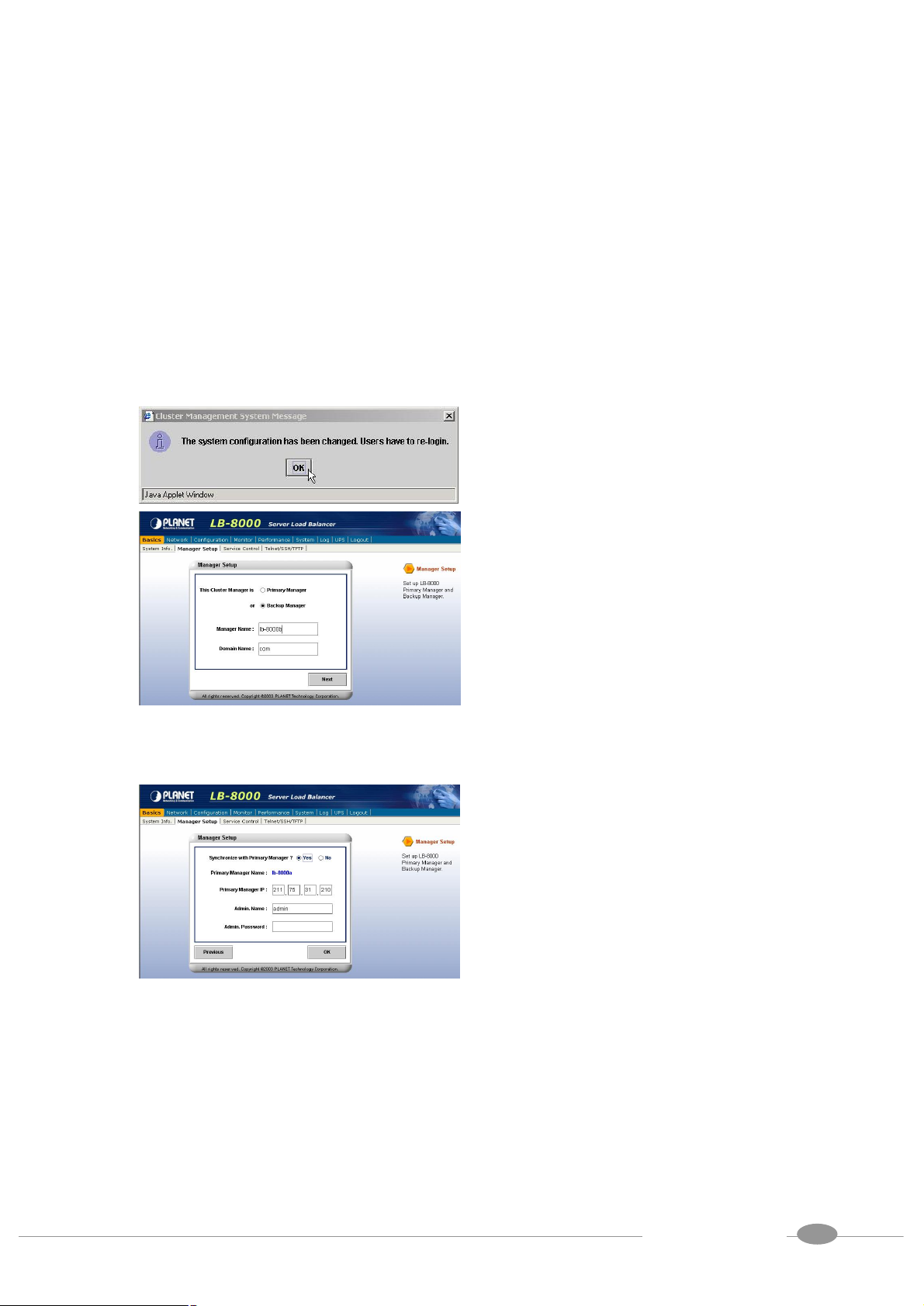
14
this manager setup page, please select
(10) After you login again, please click on
[Basics] and then click on [Manager
Setup] to setup primary manager. In
[Primary Manager] and enter the
Manager Name and Domain Name in
the filed. For example,
“lb8000-primary” and
“planet.com.tw” then click on [Next]
button.
(11) In this time, we do not need to setup
backup manager, so please select
[No] and then click on [OK] button.
(12) Click on [OK] to complete primary
setup task.
3.2. Setup by using CLI
Here are the sample steps of configuring primary manager with CLI:
14
User Manual for LB-8000 R2.6.2
PLANET Technology Corp.
Page 24

15
command to check the current network
LB-8000 R2.6.2 Rev. A - Planet Technology
Corp.
lb8000p login: admin
Password:
LB8000>
LB8000> ifconfig
Network 1 : Manual
IP Address : 192.168.2.1
Netmask : 255.255.255.0
Gateway : 192.168.2.1
Network 2 : Manual
IP Address : 192.168.3.1
Netmask : 255.255.255.0
Gateway : 192.168.3.254
LB8000>
(1) Use TELNET or SSH client to connect
LB-8000. The default IP of LB-8000 is
192.168.2.1; please enter “telnet
192.168.2.1” in the command prompt
and then press [Enter] key. Please
wait a moment you will see the Login
prompt. Enter the default initial Login
ID and Password: “admin” and
“admin” and then you will see the CLI
prompt of LB-8000.
(2) Now, you can issue “ifconfig”
configuration.
LB8000> ifconfig eth0 192.168.2.201
255.255.255.0 192.168.2.1
LB8000> ifconfig eth1 192.168.3.201
255.255.255.0 192.168.3.254
(3) Please configure the IP address of
network 1 interface by issuing
“ifconfig” command plus the value of
IP address, netmask and gateway.
• When you finish this
configuration, system will lose the
connection. You should re-connect
to LB-8000 again.
(4) Then, you can configure the IP
address of network 2 interface by
issuing “ifconfig” command plus the
value of IP address, netmask and
gateway too.
• When you finish this
configuration, system will lose the
connection. You should re-connect
to LB-8000 again.
15
User Manual for LB-8000 R2.6.2
PLANET Technology Corp.
Page 25

16
LB8000> setmgr primary lb8000p planet.com.tw
[setmgr] INFO: Update manager configuration is
completed.
LB8000> lsmgr
Manager Role : Primary
Manager Name : lb8000p
Domain : planet.com.tw
LB8000>
(5) Now, you can configure the role of
LB-8000 to be primary manager by
issuing “setmgr” command plus the
name of role, the hostname and the
domain name. After that you can issue
“lsmgr” to check the result.
User Manual for LB-8000 R2.6.2
PLANET Technology Corp.
16
Page 26

17
4. Setup Backup Manager
When network interface setting of primary manager is completed, and if you have other
LB-8000 machine that would be the backup manager, then you can perform the same steps as
setting primary manager to setup the backup manager.
4.1. Setup by using Web GUI
Here are the sample steps of configuring backup manager with web GUI:
(1) Use Microsoft Internet Explorer (IE) or
Netscate Navigator to connect
LB-8000. The default IP of LB-8000 is
192.168.2.1; please enter
“http://192.168.2.1” in the address bar
and then press [Enter] key. Please
wait a moment you will see the Login
screen. Enter the default initial Login
ID and Password: “admin” and
“admin” and then click on [Login]
button.
(2) On the top of the LB-8000 Graphic
User Interface (GUI) is the Primary
Function; please click on [Network].
User Manual for LB-8000 R2.6.2
PLANET Technology Corp.
17
Page 27

18
under the
Network 1
, please
” page, please
(3) After you click on [Network],
“Network” you will see the [
Setup], please click on [Network 1
Setup] to setup IP address, Netmask,
and Gateway.
(4) Please enter IP Address, Netmask,
and Gateway.
For example:
IP Address: 192.168.2.202
Netmask: 255.255.255.0
Gateway: 192.168.2.1
When you finish the task, please click
on [OK] button.
(5) When you click on [OK] button, the
screen will prompt up the re-login
window and click on [OK] to re-login.
(6) After you login again, please click on
[Network], and under “Network” you
will see the [Network 2 Setup]
click on it.
(7) In “Network 2 Setup
choose [Specify an IP address] and
enter the relevant information in all of
fields.
For example:
IP Address: 192.168.3.202
Netmask: 255.255.255.0
Gateway: 192.168.3.254 (Should be
User Manual for LB-8000 R2.6.2
PLANET Technology Corp.
18
Page 28
19
ame
”
synchronize with primary manager and
enter primary manager’s IP address (In
xample, the IP address of primary
the same as primary manager)
When you finish the task, please click
on [OK] to finish this task.
• If you are configuring DR
model or IP Tunneling model, you
can either disable network 2
interface or bond with network 1
interface card.
(8) And then screen will prompt up the
re-login window and click on [OK]
button to re-login.
(9) After you login again, please click on
[Basics] and then click on [Manager
Setup] to setup backup manager. In
this manager setup page, please
select [Backup Manager] and enter
the Manager Name and Domain N
in the filed. For example,
“lb8000-backup” and “planet.com.tw
then click on [Next] button.
(10) In this page, please select [Yes] to
this e
manager is 192.168.2.201), admin
name, and password in the each field
and then click on [OK] button to finish
the setting.
19
User Manual for LB-8000 R2.6.2
PLANET Technology Corp.
Page 29

20
command to check the current network
(11) Click on [OK] to complete backup
manager task.
4.2. Setup by using CLI
Here are the sample steps of configuring backup manager with CLI:
LB-8000 R2.6.2 Rev. A - Planet Technology
Corp.
lb8000 login: admin
Password:
LB8000>
LB8000> ifconfig
Network 1 : Manual
IP Address : 192.168.2.1
Netmask : 255.255.255.0
Gateway : 192.168.2.1
Network 2 : Manual
IP Address : 192.168.3.1
Netmask : 255.255.255.0
Gateway : 192.168.3.254
LB8000>
(1) Use TELNET or SSH client to connect
LB-8000. The default IP of LB-8000
is 192.168.2.1; please enter “telnet
192.168.2.1” in the command prompt
and then press [Enter] key. Please
wait a moment you will see the Login
prompt. Enter the default initial Login
ID and Password: “admin” and
“admin” and then you will see the CLI
prompt of LB-8000.
(2) Now, you can issue “ifconfig”
configuration.
LB8000> ifconfig eth0 192.168.2.202
255.255.255.0 192.168.2.1
(3) Please configure the IP address of
network 1 interface by issuing
“ifconfig” command plus the value of
IP address, netmask and gateway.
• When you finish this
configuration, system will lose the
connection. You should re-connect
to LB-8000 again.
20
User Manual for LB-8000 R2.6.2
PLANET Technology Corp.
Page 30

21
domain name. After that, you can issue
When the setting of backup manager is
chronization. You will see the name
LB8000> ifconfig eth1 192.168.3.202
255.255.255.0 192.168.3.254
LB8000> setmgr backup lb8000b planet.com.tw
[setmgr] INFO: Update manager configuration is
completed.
LB8000> lsmgr
Manager Role : Backup
Manager Name : lb8000b
Domain : planet.com.tw
LB8000>
(4) Then, you can configure the IP
address of network 2 interface by
issuing “ifconfig” command plus the
value of IP address, netmask and
gateway as well.
• When you finish this
configuration, system will lose the
connection. You should re-connect
to LB-8000 again.
(5) Now, you can configure the role of
LB-8000 to be backup manager by
issuing “setmgr” command plus the
name of role, the hostname and the
“lsmgr” command to check the result.
LB8000> lbsync 192.168.2.201 admin admin
[lbsync] INFO: Synchronization between two
managers is completed.
LB8000> lsmgr
Manager Role : Backup
Manager Name : lb8000b
Domain : planet.com.tw
Primary Manager Name : lb8000p
Primary Manager IP : 192.168.2.201
LB8000>
(6)
completed, you must issue “lbsync”
command with IP address, admin ID
and admin password of primary
manager to synchronize with primary
manager. Then you can issue “lsmgr”
command to check the result of
syn
and IP address of primary manager.
21
User Manual for LB-8000 R2.6.2
PLANET Technology Corp.
Page 31

22
Router
Firewall
1. Requests
5. Replies
4. Rewriting
2. Scheduling &
5. Configure Network Environment and a Cluster
The LB-8000 stores a server list with services provided by LB-8000. The LB-8000 also
dynamically updates this list to ensure that the resource of the whole cluster is being utilized.
This dynamically checking process ensures that workload has been distributed to the servers
with a fully usage. Also, LB-8000 provides the cluster service in Network Address Translation
(NAT), Direct Routing (DR), and IP Tunneling configurations. Particularly in the NAT setting, a
LB-8000 serves as the local router with which more protections are added to the local network.
5.1. NAT (Network Address Translation)
NAT is a method to translate the addresses in both outgoing and incoming datagram. NAT
procedure for cluster management is usually the best method for protecting the network from
intrusion since LB-8000 can act as a router and firewall between WAN/LAN to send requests
and response between real servers and clients. The whole network can be represented with
just one real IP address. (See Figure 5-1)
Primary
rewriting packets
Backup
3. Processing
Figure 5-1 NAT Network
User Manual for LB-8000 R2.6.2
PLANET Technology Corp.
22
Page 32

23
key. Please wait a moment you will see
5.2. Configure a Cluster in NAT Mode
After the network environment settings and the network interface settings of LB-8000 are
completed, you can perform the following steps to configure a cluster.
For configuring a cluster in NAT mode, you should setup following information:
l The cluster type
l The virtual host name
l The virtual host IP address
l The netmask value
l The service type
l The service port number
l The persistency setting
l The load distribution schedule. We support four types of schedules:
n Round Robin
n Weighted Round Robin
n Least Connection
n Weighted Least Connection
l Add real server list
l The health check method. We support:
n Content check for HTTP/HTTPS
n Port check
n ICMP check
n ARP check
n None (Means there is no health check)
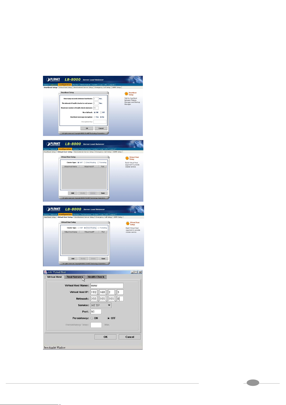
5.2.1. Setup by using Web GUI
Here are the sample steps of configuring a cluster with web GUI:
(1) Use Microsoft Internet Explorer (IE) or
Netscape Navigator to connect
LB-8000. For example, the IP of
LB-8000 is 192.168.2.201; please
enter “http://192.168.2.201”in the
address bar and then press [Enter]
User Manual for LB-8000 R2.6.2
PLANET Technology Corp.
23
Page 33

24
, you
Please enter the necessary information
the Login screen. Enter the default
initial Login ID and Password: “admin”
and “admin” and then click on [Login]
button.
(2) When you login, please click on
[Configuration] on Primary function
bar.
(3) After you click on [Configuration]
will see the [Virtual Host Setup],
please click on it to setup Virtual Host.
(4) In [Virtual Host Setup] page, please
select [NAT] and then click on [Add]
button.
(5)
to each field. Then click on [Real
Servers] tab to setup real servers.
24
User Manual for LB-8000 R2.6.2
PLANET Technology Corp.
Page 34

25
The available schedules
(6) Please use pull-down menu to select
the scheduler.
are Round Robin, Weighted Round
Robin, Least Connection, and
Weighted Least Connection.
(7) Please click on [Add] button to add
real servers.
(8) In this setup window you have two
choices. You can click on [Add Single
Server] to setup a single server or
click on [Add Multiple Servers] to
setup multiple servers.
Please enter the necessary
information to each field and then click
on [OK] button.
25
User Manual for LB-8000 R2.6.2
PLANET Technology Corp.
Page 35

26
(9) Please click on [Health Check] tab to
setup health check of real server.
(10) Please use pull-down menu to select
the health check type. The available
types are Content Check, Port Check,
ICMP Check, ARP Check and None.
(11) Please specify the timeout value of
health check and select the option of
stateful failover.
If you select “Content Check”, you
also have to specify the request page
and pattern for health check.
Then click on [OK] button to complete
this task.
User Manual for LB-8000 R2.6.2
PLANET Technology Corp.
26
Page 36

27
button, screen
(12) Please click on [Save] button to
complete the cluster setting.
(13) When you finish the cluster
configuration, please click on [Basics]
and then click on [Service Control] to
start LB-8000 service.
(14) In this page, please click on [Start]
button under the LB-8000.
(15) After you click on [Start]
will prompt up a window and then click
on [OK] to start LB-8000 service.
(16) When you click on [OK], then wait for
other window prompts up and then
click on [OK] again to wait a moment
for starting LB-8000 service.
User Manual for LB-8000 R2.6.2
PLANET Technology Corp.
27
Page 37

28
key. Please wait a moment you
” and then you will
Setup the cluster type as you preferred.
(17) In this page, under the LB-8000 you
will see the Service shows “Running”
and the State shows “Active” that
mean you have accomplished the
setting of Service Control.
5.2.2. Setup by using CLI
Here are the sample steps of configuring a cluster with CLI:
LB-8000 R2.6.2 Rev. A - PLANET Technology
Corp.
lb8000p login: admin
Password:
LB8000>
LB8000> cluster type nat
[cluster] INFO: Update cluster configuration is
completed!
LB8000> cluster
Cluster Type: NAT
LB8000>
LB8000> cluster add www 192.168.2.100
255.255.255.0 http 80 rr 0 port 1 off
[cluster] INFO: Update cluster configuration is
completed!
LB8000> cluster
Cluster Type: NAT
Virtual Host Name: WWW
Virtual Host IP: 192.168.2.100
Netmask: 255.255.255.0
Service: HTTP
Port: 80
Persistency: OFF
Scheduler: Round Robin
Health Check Type: Port Check
Check Timeout: 1
Stateful Failover: OFF
(1) Use TELNET or SSH client to connect
LB-8000. For example, the IP address
of LB-8000 is 192.168.2.201; please
enter “telnet 192.168.2.201” in the
command prompt and then press
[Enter]
will see the Login prompt. Enter the
default initial Login ID and Password:
“admin” and “admin
see the CLI prompt of LB-8000.
(2)
The default cluster type is “NAT”
model.
(3) Create a new cluster with the following
parameters by issuing “cluster”
command:
l Virtual host name
l Virtual IP
l The netmask of virtual IP
l Service type
l Service port
l The schedule of load distribution
l The persistence time
l The type of health check
28
User Manual for LB-8000 R2.6.2
PLANET Technology Corp.
Page 38

29
” check, you must enter the
completed, you can start the service of
Real Server List:
----------------------------------------------------------------
-----Real Server IP Port Weight
----------------------------------------------------------------
-----LB8000>
LB8000> rs add www 192.168.3.101-102 80 1
[rs] INFO: Update real server configuration is
completed!
LB8000> rs
Virtual Host : WWW IP Address :
192.168.2.100 Port : 80
Real Serve IP Port Weight
===================================
192.168.3.101 80 1
192.168.3.102 80 1
LB8000>
LB8000> lbsync
[lbsync] INFO: Synchronization between two
managers is completed.
l The timeout value of health check
l The stateful failover option
If you enter the type of health check to
be “content
request page and pattern to be
checked.
(4) Then you can add the real servers to
this cluster by issuing “rs” command.
When you add a real server, you must
indicate the IP address, port number
and its weight of this real server.
(5) Please issue “lbsync” command to
synchronize the settings between two
LB-8000 managers.
LB8000> lb8000 start
(6) When the setting of cluster is
[lb8000] INFO: LB-8000 starts running.
LB8000> lb8000
LB-8000
LB-8000 by issuing “lb8000”
Service: Running
State: Active
command.
LB8000>
5.3. Direct Routing
The virtual host IP address is shared by the real servers. LB-8000 also acts as a load balancer.
LB-8000 has a virtual host configured interface, which is used to accept and route request
packets to the chosen servers directly. The real server processes the requests and sends the
reply directly back to the client. LB-8000 performs direct routing technique allowing servers to
send responses straight back to the clients without going through LB-8000. (See Figure 5-2)
For the definition of Direct Routing, please refer to Administration Guide for LB-8000.
29
User Manual for LB-8000 R2.6.2
PLANET Technology Corp.
Page 39

30
Internet
LB-8000
LB-8000
3. Replies going
to the user
1. Requests
Primary
Router
Firewall
2. Scheduling
Figure 5-2 Direct Routing Network
Backup
5.3.1. Configure Linux/Unix as a real server for DR Model
We need to create an alias of the loopback adapter. This can be accomplished with the
following command, for example, where 192.168.2.100 is the virtual host IP address. On the
console of Linux, please issue following command:
# ifconfig lo:0 192.168.2.100 netmask 255.255.255.255 up
The IP address is the Virtual Host IP and Netmask must be 255.255.255.255
Execute the ifconfig command to make sure whether the installation is successful. If the
installation is successful, the following text will be shown:
1o:0 Link encap:local loopback
inet addr:192.168.2.100 Mask:255.255.255.255
UP LOOPBACK RUNNING MTU:3924 Metric:1
5.3.2. Configure Windows 2000 as a real server for DR Model
We need to create a Microsoft loopback adapter.
User Manual for LB-8000 R2.6.2
PLANET Technology Corp.
30
Page 40

31
(1) Click on [Add/Remove Hardware] icon
from control panel.
(2) On the first page of Add/Remove
Hardware Wizard, please click on
[Next] button.
(3) Select [Add/Troubleshoot a device]
then click on [Next] button.
(4) When system finished searching for
new device, please select [Add a new
device] and then click on [Next] button.
User Manual for LB-8000 R2.6.2
PLANET Technology Corp.
31
Page 41

32
(5) Select [No, I want to select the
hardware from a list] then click on
[Next] button.
(6) Select [Network Adapter] then click on
[Next] button.
(7) Select [Microsoft] from manufactures,
and then select [Microsoft Loopback
Adapter] from the network adapters.
Then click on [Next] button.
(8) Click on [Next] button to accept your
selection.
User Manual for LB-8000 R2.6.2
PLANET Technology Corp.
32
Page 42

33
(9) Click on [Finish] button.
(10) Click on [Network and Dial-up
Connections] from control panel.
(11) Right click on [Local Area Connection
2] icon and select [Properties].
(12) Select [Internet Protocol (TCP/IP)]
and then click on [Properties] button.
User Manual for LB-8000 R2.6.2
PLANET Technology Corp.
33
Page 43

34
(13) Fill in the IP address with your virtual
host IP and the Subnet mask. Then
click on [OK] button.
For example:
IP address: 192.168.2.100
Subnet mask: 255.255.255.0
(14) Click on [OK] button to accept the
changes.
(15) Enter Command Prompt and key in
command as “route print” then it will
list out the routing table. In the routing
table, you can find out two entries with
“Destination” is “192.168.2.0”.
(16) Use “Notepad” and edit an entry as
“route delete 192.168.2.0 mask
255.255.255.0 192.168.2.100” and
save as a file as “c:\route_del.bat”.
User Manual for LB-8000 R2.6.2
PLANET Technology Corp.
34
Page 44

35
(17) Click on “Start”, point to
“Programs\Accessories\System
Tools\Scheduled Tasked”. Click on
[Add Scheduled Task] to add a new
task.
(18) Click on [Next] button.
(19) Click on [Browse] to select the file.
(20) Select the file “c:\route_del.bat”.
User Manual for LB-8000 R2.6.2
PLANET Technology Corp.
35
Page 45

36
(21) In this window, select the item [when
my computer starts].
(22) Then, it will ask for administrator
authority to enable this procedure.
Please enter the user name as
“Administrator” and its password.
(23) Click [Finish] and reboot the system.
(24) After rebooting the system, enter
“Command Prompt” and key in
command as “route print” to list out the
routing table. You can see only one
“192.168.2.0” entry left. It means
system setup successfully and can
perform as a “Direct Routing” real
server.
User Manual for LB-8000 R2.6.2
PLANET Technology Corp.
36
Page 46

37
key. Please wait a moment you will see
5.4. Configure a Cluster in Direct Routing Mode
After the network environment settings and the network interface settings of LB-8000
managers are completed, you can perform the following steps to configure a cluster.
For configuring a cluster in DR mode, you should setup following information:
l The cluster type
l The virtual host name
l The virtual host IP address
l The netmask value
l The service type
l The service port number
l The persistency setting
l The load distribution schedule. We support four types of schedules
n Round Robin
n Weighted Round Robin
n Least Connection
n Weighted Least Connection
l Add real server list
l The health check method. We support:
n Content check for HTTP/HTTPS
n Port check
n ICMP check
n ARP check
n None (Means there is no health check)
5.4.1. Setup by using Web GUI
Here are the sample steps of configuring a cluster with web GUI:
(1) Use Microsoft Internet Explorer (IE) or
Netscape Navigator to connect
LB-8000. For example, the IP of
LB-8000 is 192.168.2.201; please
enter “http://192.168.2.201”in the
address bar and then press [Enter]
User Manual for LB-8000 R2.6.2
PLANET Technology Corp.
37
Page 47
38
, you
the Login screen. Enter the default
initial Login ID and Password: “admin”
and “admin” and then click on [Login]
button.
(2) When you login, please click on
[Configuration] on Primary Function
bar.
(3) After you click on [Configuration]
will see the [Virtual Host Setup],
please click on it to setup Virtual Host.
(4) In [Virtual Host Setup] page, please
select [Direct Routing] and then click
on [Add] button.
(5) Please enter the necessary
information to each field. Then click on
[Real Servers] tab to setup real
servers.
User Manual for LB-8000 R2.6.2
PLANET Technology Corp.
38
Page 48

39
The available schedules
to setup a single server or click
(6) Please use pull-down menu to select
the scheduler.
are Round Robin, Weighted Round
Robin, Least Connection, and
Weighted Least Connection. For more
information about Scheduler, please
refer to Administration Guide for
LB-8000.
(7) Please click on [Add] button to add
real servers.
(8) In this setup window you have two
choices. You can click on [Add Single
Server]
on [Add Multiple Servers] to setup
multiple servers.
Please enter the necessary
information to each field and then click
on [OK] button.
39
User Manual for LB-8000 R2.6.2
PLANET Technology Corp.
Page 49

40
If you select “Content Check”, you also
(9) Please click on [Health Check] tab to
setup health check of real server.
(10) Please use pull-down menu to select
the health check type. The available
types are Content Check, Port Check,
ICMP Check, ARP Check and None.
For more information about Health
Check, please refer to Administration
Guide for LB-8000.
(11) Please specify the timeout value of
health check and select the option of
stateful failover.
have to specify the request page and
pattern for health check.
Then click on [OK] button to complete
this task.
40
User Manual for LB-8000 R2.6.2
PLANET Technology Corp.
Page 50

41
button, screen
(12) Please click on [Save] button to
complete the cluster setting.
(13) When you finish the cluster
configuration, please click on [Basics]
and then click on [Service Control] to
start LB-8000 service.
(14) In this page, please click on [Start]
button under the LB-8000.
(15) After you click on [Start]
will prompt up a window and then click
on [OK] to start LB-8000 service.
(16) When you click on [OK], then wait for
other window prompts up and then
click on [OK] again to wait a moment
for starting LB-8000 service.
User Manual for LB-8000 R2.6.2
PLANET Technology Corp.
41
Page 51

42
, the IP address of
Setup the cluster type as you preferred.
(17) In this page, under the LB-8000 you
will see the Status shows “Running”
and the State shows “Active” that
mean you have accomplished the
setting of Service Control.
5.4.2. Setup by using CLI
Here are the sample steps of configuring a cluster with CLI:
LB-8000 R2.6.2 Rev. A - PLANET Technology
Corp.
lb8000p login: admin
Password:
LB8000>
LB8000> cluster type direct
[cluster] INFO: Update cluster configuration is
completed!
LB8000> cluster
Cluster Type: DIRECT
LB8000>
LB8000> cluster add www 192.168.2.100
255.255.255.0 http 80 rr 0 port 1 off
[cluster] INFO: Update cluster configuration is
completed!
LB8000> cluster
Cluster Type: DIRECT
Virtual Host Name: WWW
Virtual Host IP: 192.168.2.100
Netmask: 255.255.255.0
Service: HTTP
Port: 80
Persistency: OFF
Scheduler: Round Robin
Health Check Type: Port Check
Check Timeout: 1
Stateful Failover: OFF
(1) Use TELNET or SSH client to connect
LB-8000. For example
LB-8000 is 192.168.2.201; please enter
“telnet 192.168.2.201” in the command
prompt and then press [Enter] key.
Please wait a moment you will see the
Login prompt. Enter the default initial
Login ID and Password: “admin” and
“admin” and then you will see the CLI
prompt of LB-8000.
(2)
The default cluster type is “nat” model.
Please change it to be “direct”.
(3) Create a new cluster with the following
parameters by issuing “cluster”
command:
l Virtual host name
l Virtual IP
l The netmask of virtual IP
l Service type
l Service port
l The schedule of load distribution
l The persistence time
42
User Manual for LB-8000 R2.6.2
PLANET Technology Corp.
Page 52

43
s to this
indicate the IP address, port number and
uster is completed,
Real Server List:
----------------------------------------------------------------
-----Real Server IP Port Weight
----------------------------------------------------------------
-----LB8000>
LB8000> rs add www 192.168.3.101-102 80 1
[rs] INFO: Update real server configuration is
completed!
LB8000> rs
Virtual Host : WWW IP Address :
192.168.2.100 Port : 80
Real Serve IP Port Weight
===================================
192.168.3.101 80 1
192.168.3.102 80 1
LB8000>
LB8000> lbsync
[lbsync] INFO: Synchronization between two
managers is completed.
l The type of health check
l The timeout value of health check
l The stateful failover option
If you enter the type of health check to
be “content” check, you also should
enter the request page and pattern to
be checked.
(4) Then you can add the real server
cluster by issuing “rs” command.
When you add a real server, you should
its weight of this real server.
(5) Please issue “lbsync” command to
synchronize the settings between two
LB-8000 managers.
LB8000> lb8000 start
(6) When the setting of cl
[lb8000] INFO: LB-8000 starts running.
LB8000> lb8000
LB-8000
you can start the service of LB-8000 by
issuing “lb8000” command.
Service: Running
State: Active
LB8000>
5.5. IP Tunneling (Network Address Translation)
It is a technique to encapsulate IP datagram within IP datagrams, which allows datagrams
destined for one IP address to be warped and redirected to another IP address. So far, only
Linux support this IP forwarding mechanism. (See Figure 5-3)
43
User Manual for LB-8000 R2.6.2
PLANET Technology Corp.
Page 53

44
Internet
Subnet
A
Subnet
B
Tunnel
Cluster
A
Cluster
B
2. Scheduling
the user directly
3. Replies going to
(192.168.5.xxx)
(Encapsulation)
Figure 5-3 IP Tunneling
(192.168.10.xxx)
5.5.1. Configure Linux/Unix as a real server for IP Tunneling Model
Currently, you just can use Linux / UNIX as the real server on IP Tunneling model. Here is an
example to create a tunnel interface on Linux.
On the console of Linux, please issue following command:
# ifconfig tunl0 192.168.2.100 netmask 255.255.255.255 -arp up
Execute the “ifconfig” to make sure whether the installation is successful. If the installation is
successful, the output of executing "ifconfig -l" should be looking like the following text:
Link encap: IPIP Tunnel HWaddr
inet addr: 192.168.2.100 Mask: 255.255.255.255
UP RUNNING NOARP MTU:1480 Metric: 1
RX PACKETS: 0 errors:0 dropped:0 overruns:0 frame:0
TX PACKETS: 0 errors:0 dropped:0 overruns:0 carrier:0
collisions: 0 txqueuelen: 0
User Manual for LB-8000 R2.6.2
PLANET Technology Corp.
44
Page 54

45
key. Please wait a moment you will see
5.6. Configure a Cluster in IP Tunneling Mode
After the network environment settings and the network interface settings of primary and
backup managers are completed, you can perform the following steps to configure a cluster.
For configuring a cluster in IP Tunneling mode, you should setup following information:
l The cluster type
l The virtual host name
l The virtual host IP address
l The netmask value
l The service type
l The service port number
l The persistency setting
l The load distribution schedule. We support four types of schedules
n Round Robin
n Weighted Round Robin
n Least Connection
n Weighted Least Connection
l Add real server list
l The health check method. We support:
n Content check for HTTP/HTTPS
n Port check
n ICMP check
n ARP check
n None (Means there is no health check)
5.6.1. Setup by using Web GUI
Here are the sample steps of configuring a cluster with web GUI:
(1) Use Microsoft Internet Explorer (IE) or
Netscape Navigator to connect
LB-8000. For example, the IP of
LB-8000 is 192.168.2.201; please
enter “http://192.168.2.201”in the
address bar and then press [Enter]
User Manual for LB-8000 R2.6.2
PLANET Technology Corp.
45
Page 55

46
, you
Please enter the necessary information
the Login screen. Enter the default
initial Login ID and Password: “admin”
and “admin” and then click on [Login]
button.
(2) When you login, please click on
[Configuration] on Primary function
bar.
(3) After you click on [Configuration]
will see the [Virtual Host Setup],
please click on it to setup Virtual Host.
(4) In [Virtual Host Setup] page, please
select [Tunneling] and then click on
[Add] button.
(5)
to each field. Then click on [Real
Servers] tab to setup real servers.
46
User Manual for LB-8000 R2.6.2
PLANET Technology Corp.
Page 56

47
The available schedules
tup a single server or click
(6) Please use pull-down menu to select
the scheduler.
are Round Robin, Weighted Round
Robin, Least Connection, and
Weighted Least Connection. For more
information about Scheduler, please
refer to Administration Guide for
LB-8000.
(7) Please click on [Add] button to add
real servers.
(8) In this setup window you have two
choices. You can click on [Add Single
Server] to se
on [Add Multiple Servers] to setup
multiple servers.
If you select to add a single server,
please enter the necessary information
to each field and then click on [OK]
button.
If you select to add multiple servers,
please enter the necessary information
to each filed and then click on [OK]
button.
47
User Manual for LB-8000 R2.6.2
PLANET Technology Corp.
Page 57

48
ou also
(9) Please click on [Health Check] tab to
setup health check of real server.
(10) Please use pull-down menu to select
the health check type. The available
types are Content Check, Port Check,
ICMP Check, ARP Check and None.
For more information about Health
Check, please refer to Administration
Guide for LB-8000.
(11) Please specify the timeout value of
health check and select the option of
stateful failover.
If you select “Content Check”, y
have to specify the request page and
pattern for health check.
Then click on [OK] button to complete
this task
(12) Please click on [Save] button to
complete the cluster setting.
User Manual for LB-8000 R2.6.2
PLANET Technology Corp.
48
Page 58

49
button, screen
(13) When you finish the cluster
configuration, please click on [Basics]
and then click on [Service Control] to
start LB-8000 service.
(14) In this page, please click on [Start]
button under the LB-8000.
(15) After you click on [Start]
will prompt up a window and then click
on [OK] to start LB-8000 service.
(16) When you click on [OK], then wait for
other window prompts up and then
click on [OK] again to wait a moment
for starting LB-8000 service.
(17) In this page, under the LB-8000 you
will see the Status shows “Running”
and the State shows “Active” that
mean you have accomplished the
setting of Service Control.
5.6.2. Setup by using CLI
Here are the sample steps of configuring a cluster with CLI:
49
User Manual for LB-8000 R2.6.2
PLANET Technology Corp.
Page 59

50
key. Please wait a moment you
” and then you will
Setup the cluster type as you preferred.
LB-8000 R2.6.2 Rev. A - Planet Technology
Corp.
lb8000p login: admin
Password:
LB8000>
LB8000> cluster type tunnel
[cluster] INFO: Update cluster configuration is
completed!
LB8000> cluster
Cluster Type: TUNNEL
LB8000>
LB8000> cluster add www 192.168.2.100
255.255.255.0 http 80 rr 0 port 1 off
[cluster] INFO: Update cluster configuration is
completed!
LB8000> cluster
Cluster Type: TUNNEL
Virtual Host Name: WWW
Virtual Host IP: 192.168.2.100
Netmask: 255.255.255.0
Service: HTTP
Port: 80
Persistency: OFF
Scheduler: Round Robin
Health Check Type: Port Check
Check Timeout: 1
Stateful Failover: OFF
Real Server List:
----------------------------------------------------------------
-----Real Server IP Port Weight
----------------------------------------------------------------
-----LB8000>
(1) Use TELNET or SSH client to connect
LB-8000. For example, the IP address
of LB-8000 is 192.168.2.201; please
enter “telnet 192.168.2.201” in the
command prompt and then press
[Enter]
will see the Login prompt. Enter the
default initial Login ID and Password:
“admin” and “admin
see the CLI prompt of LB-8000.
(2)
The default cluster type is “nat” model.
Please change it to “tunnel”.
(3) Create a new cluster with the following
parameters by issuing “cluster”
command:
l Virtual host name
l Virtual IP
l The netmask of virtual IP
l Service type
l Service port
l The schedule of load distribution
l The persistence time
l The type of health check
l The timeout value of health check
l The stateful failover option
If you enter the type of health check to
be “content” check, you also should
enter the request page and pattern to
LB8000> rs add www 192.168.3.101-102 80 1
[rs] INFO: Update real server configuration is
completed!
LB8000> rs
Virtual Host : WWW IP Address :
192.168.2.100 Port : 80
be checked.
(4) Then you can add the real servers to
this cluster by issuing “rs” command.
When you add a real server, you
should indicate the IP address, port
number and its weight of this real
50
User Manual for LB-8000 R2.6.2
PLANET Technology Corp.
Page 60

51
completed, you can start the service of
Real Serve IP Port Weight
===================================
192.168.3.101 80 1
192.168.3.102 80 1
LB8000>
LB8000> lbsync
[lbsync] INFO: Synchronization between two
managers is completed.
LB8000> lb8000 start
[lb8000] INFO: LB-8000 starts running.
LB8000> lb8000
LB-8000
Service: Running
State: Active
LB8000>
server.
(5) Please issue “lbsync” command to
synchronize the settings between two
LB-8000 managers.
(6) When the setting of cluster is
LB-8000 by issuing “lb8000”
command.
51
User Manual for LB-8000 R2.6.2
PLANET Technology Corp.
Page 61

52
6. GUI Configuration
Before you start to use GUI or CLI, we suggest that you go through the Administration Guide
for LB-8000 R2.6.2 to get the administrative information of the technology of LB-8000.
The Graphic User Interface (GUI) of LB-8000 is a java-based administration tool. It allows
administrators to monitor system and also to achieve administrative tasks. (See Figure 6-2)
Following are the system tasks that can be completed via GUI (Graphical User Interface) from
any Java Applet enabled web browser:
ü To show the status of the whole system and to enable the system service
controlling (i.e. shut down or restart High Availability service) via web browser.
ü To show a graphical performance history of the CPU, Memory and Network
Interface by different time frame.
ü To display the system’s alert logs and connection status.
ü To add/modify/delete cluster and real servers.
6.1. Where to Start
After you install the LB-8000 into your network environment, then you can connect LB-8000 via
browser or Telnet / SSH to use cluster management system. If you choose to use browser to
do the management, please open up the IE or Netscape Navigator and connect to the login
screen, for example, the default IP of LB-8000 is 192.168.2.1; please enter
“http://192.168.2.1” and press [Enter] key, administrator will see the following GUI login
screen: (See Figure 6-1)
If your client computer does not install JRE (Java Runtime Environment) program, LB-8000
manager will pop up a window to remind you to download the JRE program when you first time login
LB-8000 manager. Please download and install the JRE program. We have confirmed that current GUI
works with following JRE versions: JRE 1.4.0, 1.4.0_01, 1.4.0_02, 1.4.0_03, 1.4.0_04, 1.4.1_02,
1.4.1_03.
User Manual for LB-8000 R2.6.2
PLANET Technology Corp.
52
Page 62

53
Help Tip
Figure 6-1 LB-8000 Login Screen
Enter the Login ID and password (the initial login ID is “admin” and the password is “admin” as
well) first, and hit [Login] to enter the main screen of LB-8000. Once administrator logins the
LB-8000 properly, further configuration process can be started.
There are nine Primary functions available and they are Basics, Network, Configuration,
Monitor, Performance, System, Log, UPS, and Logout. On the top area of main screen is
the Primary Function List. Under the Primary Function List is the Sub Function List. On the
middle of the main screen is the Content Area. On the right area of main screen is Help Tips.
(See Figure 6-2)
Primary Function List
Figure 6-2 Main screen
Sub Function List
Content Area
53
User Manual for LB-8000 R2.6.2
PLANET Technology Corp.
Page 63

54
6.2. Basics
Click on [Basics] on the Primary Function List, screen will display the System information in
the Content Area and there are also four sub functions available under [Basics] which are
System Info, Manager Setup, Service Control, and Telnet / SSH / TFTP. These sub
functions allow administrator to view system information, to set the role of LB-8000, to
shutdown or restart the LB-8000 service and SNMP service, to enable or disable the SSH,
Telnet, and TFTP service. (See Figure 6-3)
Figure 6-3 Basics screen
6.2.1. System Info
Click on [System Info], and the system information and hardware specifications will be
displayed on the Content Area: (See Figure 6-4)
54
User Manual for LB-8000 R2.6.2
PLANET Technology Corp.
Page 64

55
Figure 6–4 System Info Screen
<Operating System>: Display the version of operating system.
<Version>: Display the software version of LB-8000.
<Registration Number>: Display the legal registration number of LB-8000.
<CPU>: Display the brand name of CPU.
<CPU Speed>: Display CPU processing speed.
<Memory Size>: Display the size of RAM.
<Network Interface>: Display the type of network card interfaces.
You could view the same information by executing “sysinfo” command in CLI mode. For more
information, please refer to page 163.
6.2.2. Manager Setup
Click on [Manager Setup] and administrator can set LB-8000 to be a primary manager or a
backup manager. Primary Manger behaves as a main LB-8000 manger that manages and
controls all services. Backup Manager is responsible for taking over and continuing to serve
the tasks when primary manager stops functioning. (See Figure 6-5)
You can configure the following settings:
l Configuring the role of LB-8000: Select the current LB-8000 as primary manager or
backup manager, and setup its manager name and domain name.
l Configuring the synchronization with other manager: You can determine the current
manager synchronizes to other manager or not. If yes, you have to enter the IP address
of other manager and enter the administrator’s account and password of other manager
for authorization.
User Manual for LB-8000 R2.6.2
PLANET Technology Corp.
55
Page 65

56
Figure 6-5 Manager Setup Screen
To Set A LB-8000 As A Primary Manager and Synchronize With Backup Manager:
1. On the Manager Setup screen, please check primary manager.
2. Enter a short name for your primary manager.
3. Enter the Domain Name and click on [Next].
4. On next screen, please select [Yes] for synchronizing with backup manager (If you
do not have the Backup Manager, please select [No] and then click on [OK] to
complete the manager setup process). (See Figure 6-6)
5. Enter Backup Manager IP address in the field.
6. Enter administrator’s name and password in the fields.
7. Click on [OK] to complete the manager setup process.
Figure 6-6 Manager Setup Screen
To Setup LB-8000 As A Backup Manager:
1. On the Manager Setup screen, check backup manager.
56
User Manual for LB-8000 R2.6.2
PLANET Technology Corp.
Page 66

57
2. Enter a short name for your backup manager.
3. Enter the Domain Name and click on [Next].
4. On the next screen, if synchronizing with primary manager is needed, please select
[Yes] and then go on the next step. If synchronizing with primary manager is not
needed, please select [NO] and then click on [OK] to complete the manager setup.
(See Figure 6-7)
5. Enter primary manager IP address in the field.
6. Enter administrator’s name and password in the fields.
7. Click on [OK] to complete the manager setup process.
Figure 6-7 Backup Manager Setup Screen
You could configure same function by executing “setmgr” and “lbsync” command in CLI
mode. For more information, please refer to page 125 and 126.
6.2.3. Service Control
Click on [Service Control], and administrator can start or stop the LB-8000 service (High
Availability) and SNMP service online. (See Figure 6-8)
The “service” field has two statuses:
l Running: The service is running.
l Stopped: The service is stopped.
When LB-8000 service is running, there are two states of LB-8000 service:
l Active: The current manager is providing HA service.
57
User Manual for LB-8000 R2.6.2
PLANET Technology Corp.
Page 67

58
l Standby: The current manager is ready to takeoff HA service when active manager is
down.
To turn on / off the LB-8000 (High Availability) service, please click on [Service Control] and
hit the [Start] / [Stop] button under LB-8000. (See Figure 6-8)
To turn on / off the SNMP service, please click on [Service Control] and hit [Start] / [Stop]
button under SNMP Agent. (See Figure 6-8)
You are just able to start LB-8000 (High Availability) service after you configure a cluster. And if
you click [Start] / [Stop] button under LB-8000, both manager will start / stop service
simultaneously.
Figure 6-8 Service Control Screen
You could configure same function by executing “lb8000” and “snmp” command in CLI mode.
For more information, please refer to page 錯誤! 尚未定義書籤。 and 146.
6.2.4. Telnet / SSH / TFTP
Telnet and SSH is a network connectivity tool. Administrator can configure LB-8000 via CLI
(Command Line Interface) with TELNET or SSH client. Click on [Telnet / SSH / TFTP], and
administrator can enable / disable Telnet and SSH services. (See Figure 6-9)
User Manual for LB-8000 R2.6.2
PLANET Technology Corp.
58
Page 68

59
Figure 6-9 Telnet / SSH / TFTP Screen
Administrator also can enable TFTP service to allow TFTP client to upload files to LB-8000 or
download files from LB-8000. For example, you can download the backup system
configuration file from LB-8000 or upload the backup system configuration file to LB-8000 for
restoring previous system configurations. The files have been uploaded only can be seen from
CLI.
To enable / disable the SSH service, please click on [Telnet / SSH / TFTP] and then check or
uncheck the box beside the [Enable SSH]. (See Figure 6-9)
To enable / disable the Telnet service, please click on [Telnet / SSH / TFPT] and then check or
uncheck the box beside the [Enable Telnet]. (See Figure 6-9)
To enable /disable the TFTP service, please click on [Telnet / SSH / TFTP] and then check or
uncheck the box beside the [Enable TFTP]. (See Figure 6-9)
You could configure TFTP service by executing “tftp” command in CLI mode. For more
information, please refer to page 178.
6.3. Network
Click on [Network] on the Primary Function List, screen will display the network configuration
in the Content Area and there are also six sub functions available under [Network] which are
Network Info, Network 1 Setup, Network 2 Setup, Router Setup, DNS Setup, and VPN
Setup. These sub functions allow administrator to view current network configuration, to
configure essential network properties, and to configure Static Router, DNS, and VPN service.
(See Figure 6-10)
User Manual for LB-8000 R2.6.2
PLANET Technology Corp.
59
Page 69

60
Figure 6-10 Network Screen
6.3.1. Network Info
Click on [Network Info], and administrator can view current network configuration. (See
Figure 6-11)
Figure 6-11 Network Info Screen
<Network 1/2 >: Display the configuration type of current network card.
<IP Address>: Display the IP address.
<Netmask>: Display the netmask value.
<Gateway>: Display the gateway IP address.
You could configure same function by executing “ifconfig” command in CLI mode. For more
User Manual for LB-8000 R2.6.2
PLANET Technology Corp.
60
Page 70

61
information, please refer to page 111.
6.3.2. Network 1 Setup
Click on [Network 1 Setup] and administrator can enter a specify IP address and related
information manually. (See Figure 6-12)
Figure 6-12 Network 1 Setup Screen
To Manually Specify An Address:
1. Click on [Network 1 Setup] and enter the relevant information in following field:
<IP Address>: A valid IP address.
<Netmask>: The Netmask is a 32-bit notated number using four numbers from 0
through to 255, and is separated by periods. Typically, default Netmask numbers are
255 as values, such as 255.255.255.0, for class C. No default value in this field.
<Gateway>: Current gateway IP address. There is no default value in this field
2. Click on [OK] to save the change and finish the task.
The system will be updated with a new assigned IP address and the administrator will be
asked to re-login.
Clients will lose the network connection to LB-8000 when IP address is reassigned.
Administrator can use the new IP address to reconnect to LB-8000.
You could configure same function by executing “ifconfig eth0” command in CLI mode. For
more information, please refer to page 111.
User Manual for LB-8000 R2.6.2
PLANET Technology Corp.
61
Page 71

62
6.3.3. Network 2 Setup
Click on [Network 2 Setup], and administrator can choose “Disable” to turn off this network
card’s functions, choose “Bond with the first network card” to increase network bandwidth
for Direct Routing and IP Tunneling, or choose “Specify an IP address” to enter the IP
address manually for NAT model. (See Figure 6-13)
Figure 6-13 Network 2 Setup Screen
To Disable:
1. On the Network 2 Setup screen, please check “Disable”.
2. Click on [OK] to complete this task.
To Bond with the First Network Card:
1. On the Network 2 Setup screen, please check “Bond with the first network card”.
2. Click on [OK] to complete this task.
To Manually Specify An IP Address:
1. Click on [Network 2 Setup] and enter the relevant information in all of the following
field:
<IP Address>: A valid IP address.
<Netmask>: The Netmask is a 32-bit notated number using four numbers from 0
through to 255, and is separated by periods. Typically, default Netmask numbers are
255 as values, such as 255.255.255.0, for class C. No default value in this field.
Network 1 and Network 2 can not be assigned in the same IP address that will cause
some system errors.
User Manual for LB-8000 R2.6.2
PLANET Technology Corp.
62
Page 72

63
<Virtual Gateway>: The virtual gateway IP address created by LB-8000 for real
servers in NAT model. In NAT model, the real servers must use this IP address as the
gateway. There is no default value in this field.
2. Click on [OK] to save the change and finish the task.
The system will be updated with the new configuration and the administrator will be asked to
re-login.
Clients will lose the network connection to LB-8000 when the configuration has been changed.
Administrator can use the new IP address to reconnect to LB-8000.
You could configure same function by executing “ifconfig eht1” command in CLI mode. For
more information, please refer to page 111.
6.3.4. Router Setup
Click on Router Setup, and administrator can setup static route of LB-8000. (See Figure 6-14)
Within the static route, IP forwarding or VPN, administrator can maintain the content of real
servers under NAT model. In this screen, you can configure the following settings:
l Configuring static route: You can enable / disable the static route and maintain the
static routing rules as you want.
l Configuring IP forwarding: You can enable / disable the IP forwarding mechanism or
NAT router for local area network (LAN).
Figure 6-14 Router Setup Screen
User Manual for LB-8000 R2.6.2
PLANET Technology Corp.
63
Page 73

64
To Add a Rule of Static Route
1. Click on [Static Route] tab and then check the box to enable static route.
2. Click on [Add] to add a new rule of static route. (See Figure 6-14)
3. Enter relevant information in all of the following field: (See Figure 6-15)
<Status>: Select ON or OFF to enable / disable the rule of static route.
<Destination IP>: Enter the destination IP address of this route.
Figure 6-15 Add a Rule of Static Route Screen
<Netmask>: Enter the netmask associated with the destination network address.
<Gateway>: Enter the gateway IP address that tells the router where to forward
packets whose destination address matches the route’s IP address and subnet
mask.
<Metric>: Enter the metric number of current routing rule.
4. Click on [Save] to save the task.
To Delete a Rule of Static Route
To delete a rule of static route, administrator needs to select the routing rule to be deleted from
the list and then click on [Delete] button. When the message box of reconfirmation pops up,
please click on [Yes] to finish the task. Click on [Save] to complete the task.
To Modify a Rule of Static Route
Select the rule of static route to be modified, and click on [Modify] button, then you can make
the modification on “Modify a routing rule” screen. Click on [OK] button and then click on
[Save] to complete the task. (See Figure 6-16)
User Manual for LB-8000 R2.6.2
PLANET Technology Corp.
64
Page 74

65
Figure 6-16 Modify a Routing Rule
You could configure same function by executing “route” command in CLI mode. For more
information, please refer to page 138.
To Configure a Rule of IP Forward / NAT
1. Click on [IP Forward] tab and then check or uncheck the services. (See Figure 6-17)
Figure 6-17 IP Forward Screen
<Disable IP forwarding from WAN>: Check to disable IP forwarding from WAN or
leave box black or uncheck to enable the service.
<Disable IP forwarding form LAN>: Check to disable IP forwarding from LAN or
leave the box blank or uncheck to enable the service.
<Enable NAT>: Check to enable NAT or leave the box blank or uncheck to disable
the service.
2. Click on [Save] to save the task.
You could configure same function by executing “ipforward” command in CLI mode. For more
information, please refer to page 141.
User Manual for LB-8000 R2.6.2
PLANET Technology Corp.
65
Page 75

66
6.3.5. DNS Setup
Click on DNS Setup, and administrator can assign the address of the Domain Name Server.
DNS service enables the system to send notification for system failure via email. The DNS
address must be assigned before email alerts could take effects. (See Figure 6-18)
LB-8000 also provides a DNS proxy for any clients or real servers which use LB-8000 as
domain name server.
Figure 6-18 DNS Setup Screen
1. Enter relevant information in all of the following fields:
<Primary DNS>: The IP address of Primary DNS Server.
<Secondary DNS>: The IP address of Secondary DNS Server.
2. Click on [OK] to save the changes and complete the task.
You could configure same function by executing “dns” command in CLI mode. For more
information, please refer to page 130.
6.3.6. VPN Setup
Click on VPN Setup, and administrator can enable or disable virtual private network (VPN)
service on LB-8000. With VPN technology, the administrator can connect to real servers for
maintenance in a security way under NAT model. (See Figure 6-19)
User Manual for LB-8000 R2.6.2
PLANET Technology Corp.
66
Page 76

67
Figure 6-19 VPN Setup
To Enable PPTP (Point To Point Tunneling Protocol
1. On the VPN Setup screen, please check to enable PPTP (Point to Point Tunneling
Protocol). (See Figure 6-19)
2. Click on [Add] to add a new user. (See Figure 6-20)
Figure 6-20 Add a New User
<User Name>: Type in the name of the user name you would like to add.
<Password>: Type in the password for this new added user.
<Retype Password>: Retype to confirm the password.
3. Enter the remote IP address range in the fields. (See Figure 6-19)
4. Click on [Save] to save the task.
If the IP range of VPN cover the IP address of LB-8000 or real server then it would
occasion system errors.
To Delete a User
User Manual for LB-8000 R2.6.2
67
PLANET Technology Corp.
Page 77

68
1. On the VPN Setup screen, please click on [Delete] to delete the user. (See Figure
6-19)
2. Click on [Save] to save the task.
To Modify the Password of an Existing User
1. On the VPN Setup screen, please click on [Modify] to change user’s password. (See
Figure 6-22)
<Password>: Type in a new password for the user.
<Retype Password>: Retype to confirm the new password.
2. Click on [Save] to save the task.
Figure 6-21 Modify a User
To Disable PPTP (Point To Point Tunneling Protocol)
1. On the VPN Setup screen, please leave the box blank or uncheck to disable the
PPTP service (Point to Point Tunneling Protocol). (See Figure 6-19)
2. Click on [Save] to save the task.
You could configure same function by executing “vpn” command in CLI mode. For more
information, please refer to page 136.
6.4. Configuration
Click on [Configuration] on the Primary Function List, screen will display the heartbeat setup
in the Content Area and there are also five sub functions available under [Configuration]
68
User Manual for LB-8000 R2.6.2
PLANET Technology Corp.
Page 78

69
which are Heartbeat Setup, Virtual Host Setup, Nonclustered Server Setup, Emergency
Call, and SNMP Setup. These sub functions allow administrator to setup the heartbeat sent
between Primary Manager and Backup Manager, to add or modify the virtual host, to add or
modify nonclustered server, to setup an Email alert, and setup SNMP services. (See Figure
6-22)
Figure 6-22 Configuration Screen
6.4.1. Heartbeat Setup
Click on [Heartbeat Setup] and administrator can set the heartbeat parameters between
Primary Manager and Backup Manager. Administrator also can setup the parameters of health
check to real servers. (See Figure 6-23)
Figure 6-23 Heartbeat Setup Screen
<How many seconds between heartbeats>: The signal sending frequency of
User Manual for LB-8000 R2.6.2
PLANET Technology Corp.
69
Page 79

70
heartbeat. (The default setting is 1 seconds, and possible value is 1 to 9 seconds)
<The interval of health checks to real server>: Administrators need to set the time
of consecutive responses between LB-8000 and real servers for health checking.
(The default setting is 1 seconds, and possible value is 1 to 30 seconds)
<Maximum number of health check daemons>: Administrators need to set a
maximum number of health check daemons. (The default setting is 10 daemons, and
possible value is 1 to 30 daemons)
<Nice fail back> – Administrators can select ON then the backup manager will not
release the control when primary manager recovers from the failure. On the other
hand, if administrators select OFF then when the formally crashed primary manager
recovers, the primary manager will take the job back from the backup manager and become
active.
<Heartbeat message encryption> – Administrator can choose to encrypt the
heartbeat messages that communicate between primary and backup manager. If
administrator chooses YES, the decrypt key is needed to read the heartbeat
messages. If NO is chosen, no key is need. This is one way to avoid intruders.
<Encryption Key> – A key can be set for administrator to encrypt / decrypt the
heartbeat messages.
The frequency of heartbeat signal is higher; the time of failover is longer. In this
situation, there are some application maybe timeout to disconnect if the failover time is too
long.
You could configure same function by executing “heartbeat” command in CLI mode. For more
information, please refer to page 122.
6.4.2. Virtual Host Setup
Click on [Virtual Host Setup], and administrator can add a new virtual host, modify virtual host,
and delete virtual host. Please note that a virtual host setting up is needed before setting up
the real servers. (See Figure 6-24)
Please note that all clusters should be the same type. For example, you can not set a cluster
as NAT type and another cluster as DR type.
When you add a new cluster, you should configure the following settings:
l The virtual host configuration: Includes virtual host name, IP address, netmask value,
service protocol, service port, and persistency option.
l The real server configuration: Includes traffic forwarding scheduler, real server IP
User Manual for LB-8000 R2.6.2
PLANET Technology Corp.
70
Page 80

71
address, service port, and its weight.
l The health check configuration: Includes health check level, timeout value, and
stateful failover option.
Please do not create the entry of real servers on the DNS which LB-8000 uses.
Figure 6-24 Virtual Host Setup Screen
To Add a Virtual Host
1. Beside Cluster Type, there are three options that are NAT, Direct Routing, and
Tunneling. (See Figure 6-24)
2. Click on [Add] to add a new host you will see the following screen. (See Figure 6-25)
Figure 6-25 Add Virtual Host Screen
<Virtual Host Name>: A name for the virtual host such as “WWW” (a meaningful
name)
User Manual for LB-8000 R2.6.2
PLANET Technology Corp.
71
Page 81

72
<Virtual Host IP>: A designated IP address for virtual host such as 192.168.2.100.
<Netmask>: The netmask value of the VIP.
<Service>: Please use pull-down menu to select a type of Internet application that
supported by LB-8000. There are ten commonly used services of Internet application
such as HTTP, HTTPS, FTP, SMTP, POP3, IMAP, RTSP, MMS, E-Com and Other.
For others specific Internet application use such as SNMP service, Multimedia
service, please select Other and the port number will be used in both TCP and UDP
protocol.
<Port>: A port to be set for communication.
<Persistent>: Select ON to set a persistency time which allow client always
connects to the same real server for this period time. If OFF is selected, disable
persistency service.
3. Click on [OK] and then click on [Save] to complete the task.
To Modify a Virtual Host
Select a virtual host and click on [Modify] button on the virtual host setup screen (See Figure
6-26) to do the modification work. Click on [OK] to finish the task and then click on [Save] on
the virtual host setup screen to save the task. (See Figure 6-26)
Figure 6-26 Modify Virtual Host Screen
To Delete a Virtual Host
To delete an existing virtual host, administrator needs to select the virtual host to be removed
from the list and click on [Delete] button. When the message box of reconfirmation pops up,
please click on [Yes] to finish the task and then click on [Save] to save the task.
User Manual for LB-8000 R2.6.2
PLANET Technology Corp.
72
Page 82

73
You could configure same function by executing “cluster” command in CLI mode. For more
information, please refer to page 114.
To Add a Real server
1. Click on [Real servers] tab on Add Virtual Host screen (See Figure 6-25)
2. Please use pull-down menu to select the scheduler, there are four scheduling
algorithms available in this system such as, Round Robin, Weighted Round Robin,
Lease Connection, and Weighted Lease Connection. If you select Weighted Round
Robin or Weighted Lease Connection, then you can set the weight of the real servers
after you click on [Add] button. The default weight is 1.
3. Click on [Add] to add a new real server (See Figure 6-27) then system will pop up
other window for entering relevant information. (See Figure 6-28)
4. On this screen, administrator has two options, which are Add Single Server and
Add Multiple Servers. Administrator can select one of the options and enter
relevant information in these fields. After this step, please click on [OK] to finish the
task. When all the steps are completed, a real server list will be provided. After that,
click on [Save] on the virtual host screen to save the task.
Figure 6-27 Real servers Screen
Figure 6-28 Add Real server Screen
User Manual for LB-8000 R2.6.2
PLANET Technology Corp.
73
Page 83

74
To Modify a Real server
Administrator needs to select the real server to be modified from the list, and click on [Modify]
button then administrator can modify the real server IP address, Port, and Weight. Click on
[OK] to finish the task then click on [Save] button on Virtual Host screen to save the task. (See
Figure 6-29)
Figure 6-29 Modify Real server Screen
To Delete a Real server
To delete an existing real server, administrator needs to select the real server to be removed
from the list and click on [Delete] button. When the message box of reconfirmation pops up,
please click on [Yes] to finish the task. Then click on [Save] button on Virtual Host screen to
save the task.
You could configure same function by executing “rs” command in CLI mode. For more
information, please refer to page 118.
To Configure Health Check
1. Click on [Health Check] tab on Add / Modify Virtual Host screen (See Figure 6-25)
2. Please use pull-down menu to select the health check type, there are five types
available in this system such as, Content Check, Port Check, ICMP Check, ARP
Check, and None. (See Figure 6-30)
User Manual for LB-8000 R2.6.2
PLANET Technology Corp.
74
Page 84

75
Figure 6-30 Health Check Screen
3. Enter the Check Timeout for how many seconds are needed for LB-8000 to wait the
response from real servers before assuming that real servers are malfunction.
4. Select [ON] to enable the Stateful Failover function or select [OFF] to disable the
Stateful Failover function. (The default setting is ON)
5. Click on [OK] button to finish the task then click on [Save] button on Virtual Host
screen to save the task.
If you select content check, you also have to configure the request page and pattern for
LB-8000 to check the health of real server.
You could configure same function by executing “cluster” command in CLI mode. For more
information, please refer to page 114.
6.4.3. Nonclustered Server Setup
Click on [Non-clustered Server Setup], and administrator can add, modify or delete a
nonclustered server for monitoring by ICMP check from LB-8000. (See Figure 6-31)
User Manual for LB-8000 R2.6.2
PLANET Technology Corp.
75
Page 85

76
Figure 6-31 Nonclustered Server Setup Screen
Add Nonclustered Server
To add a nonclustered server, please click on [Add] and enter relevant information in the
following fields:
<Server Name>: Enter a meaningful server name.
<Server IP Address>: Enter a designated IP address for this server and click on [OK]
to finish this task. (See Figure 6-32)
After you click on [OK] button to finish the task, then click on [Save] button on Nonclustered
Server Setup screen to save the task.
Figure 6-32 Add Non-clustered Server Setup Screen
To Modify an Existing Nonclustered Server
Administrator needs to select the nonclustered server to be modified from the list, and click on
[Modify] first. After that, administrator can modify the Server name and Server IP. Click on
[OK] button to finish the task then click on [Save] button on Nonclustered Server Setup
screen to save the task. (See Figure 6-33)
User Manual for LB-8000 R2.6.2
PLANET Technology Corp.
76
Page 86

77
Figure 6-33 Modify Nonclustered Server Screen
To Delete an Existing Nonclustered Server
To delete an existing nonclustered server, administrator needs to select server to be deleted
from the list and click on [Delete]. When the message box of reconfirmation pops up, please
click on [Yes] button to finish the task then click on [Save] button on Nonclustered Server
Setup screen to save the task.
You could configure same function by executing “noncluster” command in CLI mode. For
more information, please refer to page 131.
6.4.4. Emergency Call Setup
With LB-8000, the authorized members will be notified by email if the system shall go wrong. In
LB-8000, each cluster can have its own members. If a cluster has some problems, like a real
server is down, the alert mail will be sent to the members of the cluster. (See Figure 6-34)
There is one default group named @LB-8000. The members of @LB-8000 will receive the
alert mails about LB-8000 manager itself. For example, if the network interface of LB-8000 is
down, LB-8000 will send an alert mail to the members of @LB-8000.
User Manual for LB-8000 R2.6.2
PLANET Technology Corp.
77
Page 87

78
Figure 6-34 Emergency Call Setup Screen
To Add Emergency Call
1. Click on [Add] to add email recipients
2. Enter the recipient’s effective email addresses. (See Figure 6-35)
Figure 6-35 Add A New Emergency Call
3. Select the virtual host from “Virtual Host List” and then click on button to
move the server to “Selected Virtual Host” field which you would like to receive the
e-mail notifications while real server or LB-8000 malfunction.
4. Click on [OK] button and [Save] button in Emergency Call Setup screen to complete
this task.
To Modify Emergency Call
Select the e-mail to be modified, and click on [Modify]. Then you can make the modification
on Modify Emergency Call Screen. Click on [OK] button and [Save] button in Emergency Call
Setup screen to complete this task. (See Figure 6-36)
User Manual for LB-8000 R2.6.2
PLANET Technology Corp.
78
Page 88

79
Figure 6-36 Modify Emergency Call Screen
To Delete Emergency Call
To delete an existing emergency call, administrator needs to select the emergency emails to
be deleted from the list and click on [Delete]. When the message box of reconfirmation pops
up, please click on [Yes] to finish the task.
You could configure same function by executing “contact” command in CLI mode. For more
information, please refer to page 127.
6.4.5. SNMP Setup
Simple Network Management Protocol (SNMP) is used to govern and monitor network devices
and their functions. You can configure the following settings:
l Configuring SNMP agent: Setup the SNMP agent with a community string to allow
access to LB-8000 SNMP information. And the SNMP agent can be disabled / enabled
when needed.
l Setup manager access: Configure the SNMP manager-IP list, from which LB-8000
SNMP agent can accept requests for SNMP information. The manager-IP list can be
modified if necessary.
l Configuring SNMP traps: You can enable / disable SNMP trap and specify the
community for specific SNMP manager. The trap messages are equivalent to mail alert
and alert log.
To configure the SNMP function, you can click [Configure] from main menu bar and then click
[SNMP Setup] on sub-menu. You can see the SNMP setup configuration screen as shown on
Figure 6-37.
User Manual for LB-8000 R2.6.2
PLANET Technology Corp.
79
Page 89

80
Figure 6-37 SNMP Setup Screen
To Enable SNMP Agent (See Figure 6-37)
1. In SNMP Setup page, please click on System Info tab.
2. Check on the check box to enable the SNMP Agent.
3. Enter relevant information in all of the following fields:
l <System Contact>: Enter the E-mail address for the person to contact regarding
issue with the LB-8000.
l <Machine Location>: Enter a machine location, such as Room 121, that
describes the physical location of the LB-8000.
l <Community String>: Enter a SNMP community string, such as ID or Password
that is used for basic SNMP security and for grouping machines that you
manage.
4. Click on [OK] button to complete the task.
To Disable SNMP Agent (See Figure 6-37)
1. In SNMP Setup page, please click on System Info tab.
2. Unmark the check box to disable the SNMP Agent.
3. Click on [OK] button to complete the task.
To Setup Manager Access (See Figure 6-38)
80
User Manual for LB-8000 R2.6.2
PLANET Technology Corp.
Page 90

81
Figure 6-38 Setup Manager Access
1. On SNMP Setup page, please click on Manager Access tab.
2. Click on [Add] button.
3. Enter relevant information in all of the following fields: (See Figure 6-39)
Figure 6-39 Add a New Manager
<IP Address or Network Address>: Enter an IP address or network Address from
which the SNMP agent can accept requests.
<Netmask (For Network Address)>: Enter the netmask for the network address in
this field.
4. Click on [OK] to complete the task.
If you enter an IP address, please enter “255.255.255.255” on the Netmask field.
To Delete A Manager Access (See Figure 6-38)
To delete an existing manager access, administrator needs to select the access to be deleted
from the list and then click on [Del] button. When the message box of reconfirmation pops up,
User Manual for LB-8000 R2.6.2
PLANET Technology Corp.
81
Page 91

82
please click on [Yes] to finish the task.
The IP address of LB-8000 has been added into the list after you change the IP address of
LB-8000 or you run a fully synchronization between two LB-8000 from GUI or by issue “lbsync <IP>
<User Account> <Password>” command in CLI mode. But you won’t see these records.
To Enable Auth Trap (See Figure 6-40)
Figure 6-40 Setup Auth Trap
1. On SNMP Setup page, please click on Trap tab.
2. Check on the box to enable the Trap service.
3. Click on [Add] button.
4. Enter relevant information in all of the following fields: (See Figure 6-41)
Figure 6-41 Add a New Target
<Target IP Address>: Enter the target IP address that should be notified when a trap
is sent by the LB-8000.
<Community>: Enter the community string which allows LB-8000 to communicate
with SNMP manager for sending trap notifications to the desired manager(s).
5. Click on [OK] button to complete the task.
82
User Manual for LB-8000 R2.6.2
PLANET Technology Corp.
Page 92

83
To Disable Auth Trap (See Figure 6-40)
1. On SNMP Setup page, please click on Trap tab.
2. Uncheck the box to disable the Trap service.
3. Click on [OK] button to complete the task.
You could configure same function by executing “snmp” command in CLI mode. For more
information, please refer to page 146.
6.5. Monitor
Click on [Monitor] on the Primary Function List, screen will display the LB-8000 monitor status
in the Content Area and there are also two sub functions available under [Monitor] which are
LB-8000 Monitor and Cluster Monitor. These sub functions allow administrator to monitor
LB-8000 machine, cluster, and real servers. (See Figure 6-42)
Figure 6-42 Monitor Screen
6.5.1. LB-8000 Monitor
Administrator can review the current system status via LB-8000 Monitor through various colors.
Green represents normal and Red represents abnormal. To obtain the detail information for a
specific server, please double-click on that specific server and the detail information needed
will be displayed. (See Figure 6-43) If the color is gray, that means the HA service is not
running or current manager is standby mode.
User Manual for LB-8000 R2.6.2
PLANET Technology Corp.
83
Page 93

84
You also can monitor the CPU usage, memory usage and network flow from LB-8000 monitor.
If the SNMP agent of real server or nonclustered server is running and can accept LB-8000
retrieve information, you also can monitor the network flow of real server or nonclustered
server.
Figure 6-43 LB-8000 Monitor Screen
Click on any online manager, and more detail information of that specific manager will be
displayed on the right area of the screen. The information will be displayed include: (See
Figure 6-44)
Figure 6-44 Manager Server Status Screen
<Managers>: The name of the selected manager.
<IP>: The designated IP of the selected manager
<Status>: The current activity status of the selected manager. “Green” color means
the manager is up, and “Red” color means the manager is down.
<SNMP Info>: Click on SNMP Info tab on top and you will be able to view LB-8000
Manager real time information on the screen. You can see the CPU Usage Memory
Usage, the inflow rate and outflow rate of network interface. (See Figure 6-45)
User Manual for LB-8000 R2.6.2
PLANET Technology Corp.
84
Page 94

85
Figure 6-45 Manager Server SNMP Info Screen
Click on any online real server, and more detail information about this particular server will be
displayed on the right of the screen. The information will be displayed include: (See Figure
6-46)
Figure 6-46 Real server Status Screen
<Real server>: The selected server.
<IP>: The designated IP of the selected server.
<Status>: The current activity status of the selected server. “Green” color means the
manager is up, and “Red” color means the manager is down.
<Service>: The services provided by the selected server.
<Port>: The listening port number.
<Status>: The current activity status of the service provided by real server. There are
three kinds of status: “UP” means service is up, “DOWN” means service is down and
“UNKNOW” means service is unknown cause the health check method is “none”.
<SNMP Info>: Click on SNMP Info tab on top, and you will be able to view the inflow
rate and outflow rate of network interface of the real server if the SNMP agent of the
real server is running. (See Figure 6-47)
User Manual for LB-8000 R2.6.2
PLANET Technology Corp.
85
Page 95

86
Figure 6-47 Real server SNMP Info Screen
Click on any online nonclustered server, and more detail information about this particular
server will be displayed on the right of the screen. The information will be displayed include:
(See Figure 6-48)
Figure 6-48 Nonclustered Server Status Screen
<Nonclustered Server>: The name of the selected server.
<IP>: The designated IP of the selected server
<Status>: The current activity status of the selected server.
<SNMP Info>: Click on SNMP Info tab on top, and you will be able to view the inflow
rate and outflow rate of network interface of the real server if the SNMP agent of the
real server is running. (See Figure 6-49)
User Manual for LB-8000 R2.6.2
PLANET Technology Corp.
86
Page 96

87
Figure 6-49 Nonclustered Server SNMP Info Screen
You could configure same function by executing “lbonitor” command in CLI mode. For more
information, please refer to page 151.
6.5.2. Cluster Monitor
From Cluster Monitor, administrator can view the status of clusters service and real servers’
service. You also can enable or disable the clusters service or real servers’ service. (See
Figure 6-50)
The status of cluster service has four states:
l Stopped: The LB-8000 service is not running.
l Enabled: The LB-8000 service is running and there is at least one real server for
forwarding requests.
l Disabling: The cluster has been disabled, but still has some connection records in
connection table. The cluster will not accept any new connection request.
l Disabled: The cluster has been disabled, and there is no connection record in connection
table. The cluster will not accept any new connection request.
The status of real servers’ service has five states:
l Stopped: The LB-8000 service is not running.
l Running: The LB-8000 service and the real server’s service are running.
l Disabling: The real server’s service has been disabled, but still has some connection
records in connection table. The real server will not accept any new connection request.
l Disabled: The real server’s service has been disabled, and there is no connection record
in connection table. The real server will not accept any new connection request.
l Down: The real server’s service is down and will not accept any new connection request.
User Manual for LB-8000 R2.6.2
PLANET Technology Corp.
87
Page 97

88
Figure 6-50 Cluster Monitor Screen
To View Cluster Status and Configure Services
1. Click on [Cluster Monitor] and then use poll-down list to select Cluster View. (See
Figure 6-50)
2. Click on the online cluster system, and more detail information will be displayed on
the right of the screen. The information will be displayed include: (See Figure 6-51)
Figure 6-51 Cluster Status
<Virtual Host Name>: The host name of virtual server.
<Virtual Host IP>: A designated IP address of virtual host.
<Port>: The listening port number of virtual host.
<Status>: The current service status of the selected cluster.
<Real server IP>: The designated IP of real server.
<Port>: The listening port number of real server.
<Weight>: The current assigned service weights of real server.
<Conns>: The total connection count of real server.
<Status>: The current service status of real server.
[Disable]: To turn off the particular real server service, just select the real server and
User Manual for LB-8000 R2.6.2
PLANET Technology Corp.
88
Page 98

89
then click on [Disable] button
[Disable All]: To turn off all of real server services, please click on [Disable All]
button.
[Enable All]: To turn on all of real server services, please click on [Enable All]
button.
To View Real server Status and Configure Services
1. Click on [Cluster Monitor] and then use poll-down list to select Real Server View.
(See Figure 6-50)
2. Click on any real server, and more detail information will be displayed on the right of
the screen. The information will be displayed include: (See Figure 6-52)
Figure 6-52 Real server Status
<Real server IP>: A designated IP address of real server.
<Virtual Host>: The host name of virtual server.
<Port>: The listening port number of real server.
<Weight>: The current assigned service weights
<Conns>: The total connection count of current service.
<Status>: The current service status of current service
[Disable]: To turn off the particular service of real server, just select the virtual host
and then click on [Disable] button
[Disable All]: To turn off all services of real server, please click on [Disable All]
button.
[Enable All]: To turn on all services of real server, please click on [Enable All]
button.
You could configure same function by executing “cmonitor” command in CLI mode. For more
information, please refer to page 153.
User Manual for LB-8000 R2.6.2
PLANET Technology Corp.
89
Page 99

90
6.6. Performance
Click on [Performance] on the Primary Function List, screen will display the Load Distribution
status of the virtual host in the Content Area and there are two sub functions available under
[Performance] which are Load Distribution and Server Performance. These sub functions
allow administrator to view the load distribution status of the virtual host and server
performance. (See Figure 6-53)
Figure 6-53 Performance Screen
6.6.1. Load Distribution
On Load Distribution screen, please click on the online cluster system, and more detail
information will be displayed on the right of the screen. The information will be displayed
include: (See Figure 6-54)
Figure 6-54 Load Distribution Screen
<Virtual Host>: The name of the virtual host.
User Manual for LB-8000 R2.6.2
PLANET Technology Corp.
90
Page 100

91
<Virtual Host IP>: A designated IP address of the virtual host.
<Port>: The listening port number.
<Real server>: The designated IP of the real server.
<Weight>: The current assigned service weights of the real server.
<Load Distribution>: The percentage of services distribution.
<Current Conns>: The number of current total connections.
You could configure same function by executing “load” command in CLI mode. For more
information, please refer to page 155.
6.6.2. Server Performance
Click on any online manager server and select any component to review the server
performance on the right of the screen. The information to be displayed includes: (See Figure
6-55)
Figure 6-55 Server Performance Screen
<CPU Usage>: Click on CPU Usage, and you will see a CPU usages status graph
on the right screen. If you click on [Day], [Month], or [Year] button, more detail
information arranged according to Day, Month, or Year will be available. (See Figure
6-55)
<Memory Usage>: Click on Memory Usage, and you will see a Memory usages
status graph on the right screen. If you click on [Day], [Month], or [Year] button,
more detail information arranged according to Day, Month, or Year will be available.
(See Figure 6-56)
User Manual for LB-8000 R2.6.2
PLANET Technology Corp.
91
 Loading...