

Page 1

2 Mega-pixel IR PoE Plus
Speed Dome IP Camera with
Extended Support
►ICA-E6265
Page 2

2 Mega-pixel IR PoE Plus Speed Dome IP Camera
2
ICA-E6265
Copyright
Copyright 2016 by PLANET Technology Corp. All rights reserved. No part of this publication may be
reproduced, transmitted, transcribed, stored in a retrieval system, or translated into any language or
computer language, in any form or by any means, electronic, mechanical, magnetic, optical, chemical,
manual or otherwise, without the prior written permission of PLANET.
PLANET makes no r epresentations or warranties, either expressed or implied, with respect to the
contents hereof and specifically disclaims any warranties, merchantability or fitness for any particular
purpose. Any software described in this manual is sold or licensed "as is". Should the programs prove
defective following their purchase, the buyer (and not PLANET, its distributor, or its dealer) assumes
the entire cost of all necessary servicing, repair, and any incidental or consequential damages
resulting from any defect in the software. Further, PLANET reserves the right to revise this publication
and to make changes from time to time in the contents hereof without obligation to notify any person of
such revision or changes.
All brand and product names mentioned in this manual are trademarks and/or registered trademarks
of their respective holders.
Federal Communication Commission Interference Statement
This equipment has been tested and found to comply with the limits for a C lass B digital device,
pursuant to Part 15 of FCC Rules. These limits are designed to provide reasonable protection against
harmful interference in a residential installation. This equipment generates, uses, and can radiate radio
frequency energy and, if not installed and used in accordance with the instructions, may cause harmful
interference to radio communications. However, there is no guarantee that interference will not occur
in a particular installation. If this equipment does cause harmful interference to radio or television
reception, which can be determined by turning the equipment off and on, the user is encouraged to try
to correct the interference by one or more of the following measures:
1. Reorient or relocate the receiving antenna.
2. Increase the separation between the equipment and receiver.
3. Connect the equipment into an outlet on a circuit different from that to which the receiver is
connected.
4. Consult the dealer or an experienced radio technician for help.
FCC Caution
To assure continued compliance, for example, use only shielded interface cables when connecting to
computer or peripheral devices. Any changes or modifications not expressly approved by the party
responsible for compliance could void the user’s authority to operate the equipment.
This device complies with Part 15 of the FCC Rules. Operation is subject to the following two
conditions: (1) This device may not cause harmful interference, and (2) this device must accept any
interference received, including interference that may cause undesired operation.
Page 3

2 Mega-pixel IR PoE Plus Speed Dome IP Camera
3
ICA-E6265
Federal Communication Commission (FCC) Radiation Exposure Statement
This equipment complies with FCC radiation exposure set forth for an uncontrolled environment. In
order to avoid the possibility of exceeding the FCC radio frequency exposure limits, human proximity
to the antenna shall not be less than 20 cm (8 inches) during normal operation.
Safety
This equipment is designed with the utmost care for the safety of those who install and use it. However,
special attention must be paid to the dangers of electric shock and static electricity when working with
electrical equipment. All guidelines of this and of the computer manufacture must therefore be allowed
at all times to ensure the safe use of the equipment.
CE Mark Warning
This is a Class B product. In a domestic environment, this product may cause radio interference, in
which case the user may be required to take adequate measures.
WEEE Regulation
To avoid the potential effects on t he environment and human health as a result of the
presence of hazardous substances in electrical and electronic equipment, end users of
electrical and electronic equipment should understand the meaning of the crossed-out
wheeled bin symbol. Do not dispose of WEEE as unsorted municipal waste; they should be
collected separately.
Revision
User’s Manual of PLANET 2 Mega-pixel IR PoE Plus Speed Dome IP Camera
Model: ICA-E6265
Rev: 2.00 (November, 2016) Part No. EM-ICA-E6265 (v2)_v2.0
Page 4

2 Mega-pixel IR PoE Plus Speed Dome IP Camera
4
ICA-E6265
Table of Contents
Chapter 1. Product Introduction ........................................................................................................ 6
1.1 Package Contents ........................................................................................................... 6
1.2 Overview .......................................................................................................................... 7
1.3 Features ........................................................................................................................ 12
1.4 Product Specifications ................................................................................................... 13
Chapter 2. Hardware Interface ........................................................................................................ 16
2.1 Physical Descriptions .................................................................................................... 16
2.1.1 Identification of ICA-E6265 Rear Panel and Connectors ................................... 16
2.1.2 Identification of ICA-E6265 Connectors ............................................................. 17
2.2 Hardware Installation ..................................................................................................... 18
2.2.1 Removing the Set Screw .................................................................................... 18
2.2.2 Inserting the Set Screw to the Safety Strap........................................................ 18
2.2.3 Attaching the Set Screw back ............................................................................. 19
2.2.4 Installing the Mounting Solution.......................................................................... 19
2.2.5 Inserting the Cable ............................................................................................. 20
2.2.6 Mounting the Camera ......................................................................................... 20
2.2.7 Attaching Ferrite Cores and Connecting Cables ................................................ 21
2.2.8 Powering on the Camera via 60-watt Ultra PoE Injector .................................... 23
2.2.9 Connecting the Camera to Network ................................................................... 23
2.3 Initial Utility Installation .................................................................................................. 24
2.4 Using UPnP of Windows XP or 7 .................................................................................. 27
2.4.1 Windows XP ....................................................................................................... 27
2.4.2 Windows 7 .......................................................................................................... 32
2.5 Setting Up ActiveX for IP Camera ................................................................................. 34
2.5.1 Internet Explorer 6 for Windows XP ................................................................... 34
2.5.2 Internet Explorer 7 for Windows XP ................................................................... 35
2.5.3 Internet Explorer 7 for Windows Vista ................................................................ 35
Chapter 3. Web-based Management .............................................................................................. 37
3.1 Introduction .................................................................................................................... 37
3.2 Connecting to IP Camera .............................................................................................. 37
3.3 Live Viewing .................................................................................................................. 39
3.4 PTZ Control Panel ......................................................................................................... 42
3.4.1 Preset ................................................................................................................. 43
3.4.2 Touring Control ................................................................................................... 48
3.4.3 Scan Control ....................................................................................................... 49
3.4.4 Auto Tracking ...................................................................................................... 50
3.5 Configuration ................................................................................................................. 53
3.6 Host Setup ..................................................................................................................... 54
3.6.1 Host .................................................................................................................... 54
3.6.2 GPS Position ...................................................................................................... 55
3.7 Date and Time ............................................................................................................... 56
3.8 Network ......................................................................................................................... 58
Page 5

2 Mega-pixel IR PoE Plus Speed Dome IP Camera
5
ICA-E6265
3.8.1 IP Address Filtering ............................................................................................ 58
3.8.2 Port Mapping ...................................................................................................... 60
3.8.3 HTTPS ................................................................................................................ 61
3.8.4 IEEE 802.1X ....................................................................................................... 62
3.8.5 SNMP Setting ..................................................................................................... 63
3.8.6 RTP ..................................................................................................................... 66
3.8.7 Network............................................................................................................... 66
3.9 IP Settings ..................................................................................................................... 69
3.9.1 Connection Type ................................................................................................. 69
3.9.2 DNS .................................................................................................................... 71
3.9.3 DDNS .................................................................................................................. 71
3.10 Video & Audio ................................................................................................................ 75
3.10.1 Camera Options ................................................................................................. 75
3.10.2 Compression ...................................................................................................... 77
3.10.3 Video ................................................................................................................... 80
3.10.4 Audio ................................................................................................................... 94
3.11 Event ............................................................................................................................. 96
3.11.1 Event Server ....................................................................................................... 96
3.11.2 Event Configuration ............................................................................................ 99
3.11.3 Event List .......................................................................................................... 106
3.11.4 Manual Event .................................................................................................... 109
3.12 Local Storage................................................................................................................ 111
3.12.1 Status ................................................................................................................. 111
3.12.2 Utilities ............................................................................................................... 112
3.12.3 File Management ............................................................................................... 115
3.13 System .......................................................................................................................... 118
3.13.1 User Account ..................................................................................................... 118
3.13.2 System Info ........................................................................................................ 11 9
3.13.3 Factory Default .................................................................................................. 119
3.13.4 Firmware Upload .............................................................................................. 120
3.13.5 Save & Reboot ................................................................................................. 121
3.13.6 Logout ............................................................................................................... 121
Appendix A. The Dimension Diagram of Stand ............................................................................... 122
Appendix B. The Dimension Diagram of Camera ............................................................................ 123
Appendix C. Ping IP Address ........................................................................................................... 124
Appendix D. Configuring Port Forwarding Manually ........................................................................ 125
Appendix E. Waterproofing the Cable Connections ........................................................................ 128
Appendix F. Joystick Compatibility .................................................................................................. 136
Appendix G. Connecting Audio Devices .......................................................................................... 137
Appendix H. Connecting Digital Input/Digital Output Devices ......................................................... 138
Appendix I. Troubleshooting & Frequently Asked Questions ......................................................... 141
Page 6
2 Mega-pixel IR PoE Plus Speed Dome IP Camera
6
Chapter 1. Product Introduction
1.1 Package Contents
The package should contain the following items:
Camera Unit x 1
Quick Installation Guide x 1
Mounting Screw Kit x 1
Cable Gland x 2
Safety Strap x 1
Ferrite Core x 3
Terminal Block x 2
ICA-E6265
60-watt Ultra PoE Injector x 1
Power Cord x 1
Desiccant Bag x 1
Bracket x 1
Mounting Label x 1
1. If any of the above items are missing, please contact your dealer immediately.
2. Using the power supply that is not the one included in the IP camera packet will cause
damage and void the warranty for this product.
Page 7

2 Mega-pixel IR PoE Plus Speed Dome IP Camera
7
ICA-E6265
1.2 Overview
Robust IR PTZ IP Camera for Demanding Surveillance
PLANET ICA-E6265, a high-performance outdoor IR PTZ speed dome surveillance camera, includes
advanced auto tracking designed for the most demanding video surveillance applications. With high
resolution of 1080p a t 60fps, endless 360° pan and 33x optical zoom capabilities, and 150-meter
adaptive IR illuminators, it enables distant objects to be monitored in sharp detail. The ICA-E6265 has
an IP66-rated housing that can withstand any harsh temperature ranging from -40°C to 55°C.
Effective Surveillance for Wide Area Coverage
When enabling the auto-tracking function, a moving object within the camera’s field of view can be
automatically detected and followed like being automatically zoomed in and f ocused on. This is
particularly beneficial in unmanned video surveillance setups with automated recording.
Page 8
2 Mega-pixel IR PoE Plus Speed Dome IP Camera
8
ICA-E6265
Extended Support with Specific Software
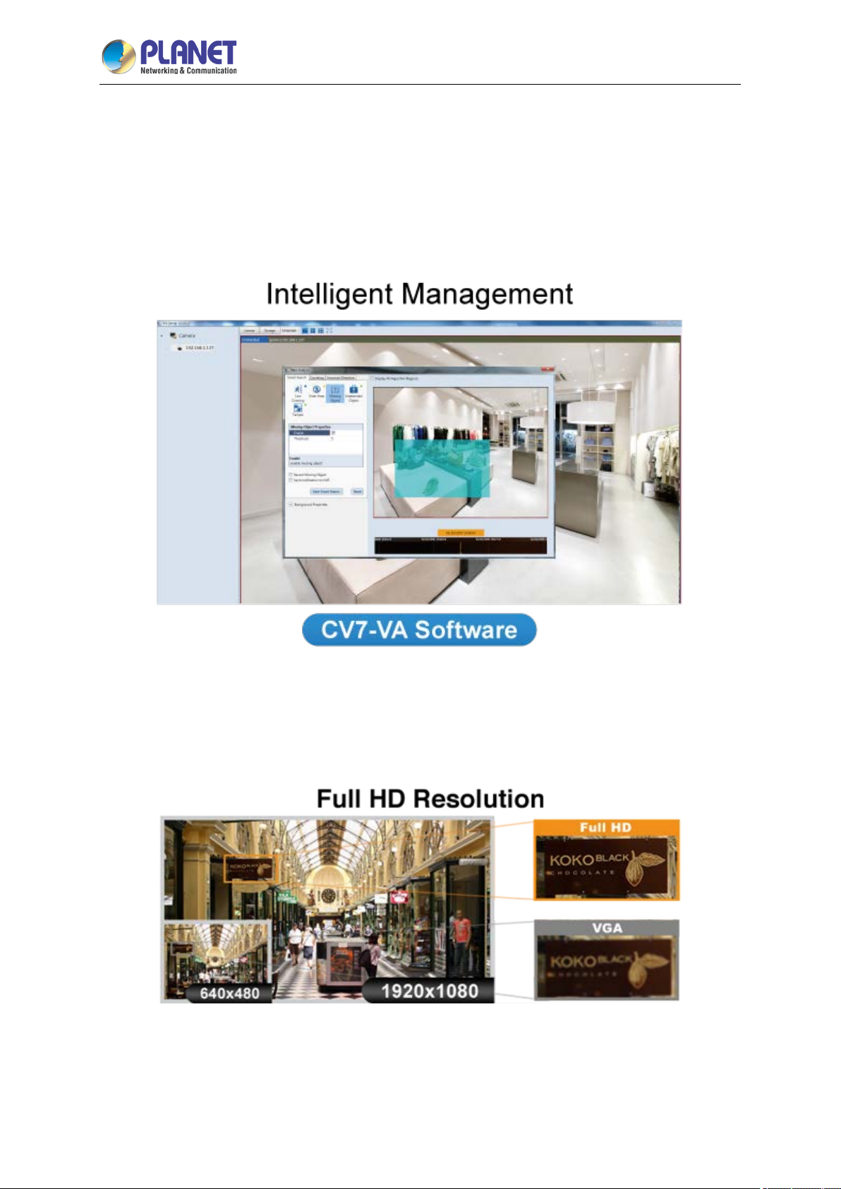
The ICA-E6265 IP camera is able to provide advanced surveillance applications with specific software
such as video analytics. It supports PLANET CV7-VA video analytics that is designed to transform
your video surveillance network into a smart detection system. The software provides Enter Area,
People Counting, Missing Object, Line Crossing, Unattended Object and Tamper functions. Once a
suspicious activity is detected, users can play back to watch these events and use them as references
or evidences if needed.
Professional, High-resolution Network Camera
The ICA-E6265 is a high-resolution camera for the round-the-clock surveillance. This camera supports
H.264 and MJPEG compression formats and delivers excellent picture quality in 2 mega-pixel
resolutions at 60 frames per second (fps).
Day & Night Functionality
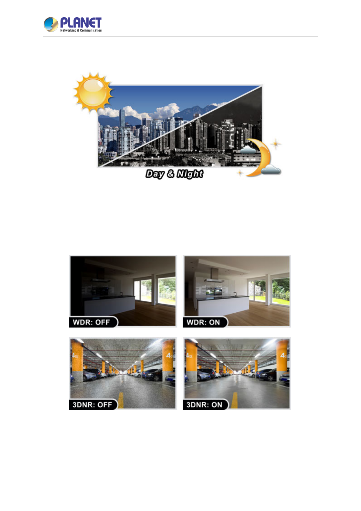
To adapt to constantly changing lighting conditions during the day and night, the ICA-E6265 comes
with a removable IR-cut filter and adaptive IR illuminators, which enable the camera to provide color
Page 9
2 Mega-pixel IR PoE Plus Speed Dome IP Camera
9
ICA-E6265
video when there is sufficient light, and black/white video in dark conditions. The ICA-E6265 is able to
maintain clear images 24 hours a day.
Exceptional Image Quality
Together with powerful image processing attributes like True Wide Dynamic Range (True WDR) and
3-dimensional Noise Reduction (3DNR) technology, the ICA-E6265 is able to filter the intense
backlight surrounding a subject and remove noises from video signal. The result is that an extremely
clear and exquisite picture quality can be produced even under any challenging lighting conditions.
Page 10
2 Mega-pixel IR PoE Plus Speed Dome IP Camera
10
ICA-E6265
High-level Outdoor Protection
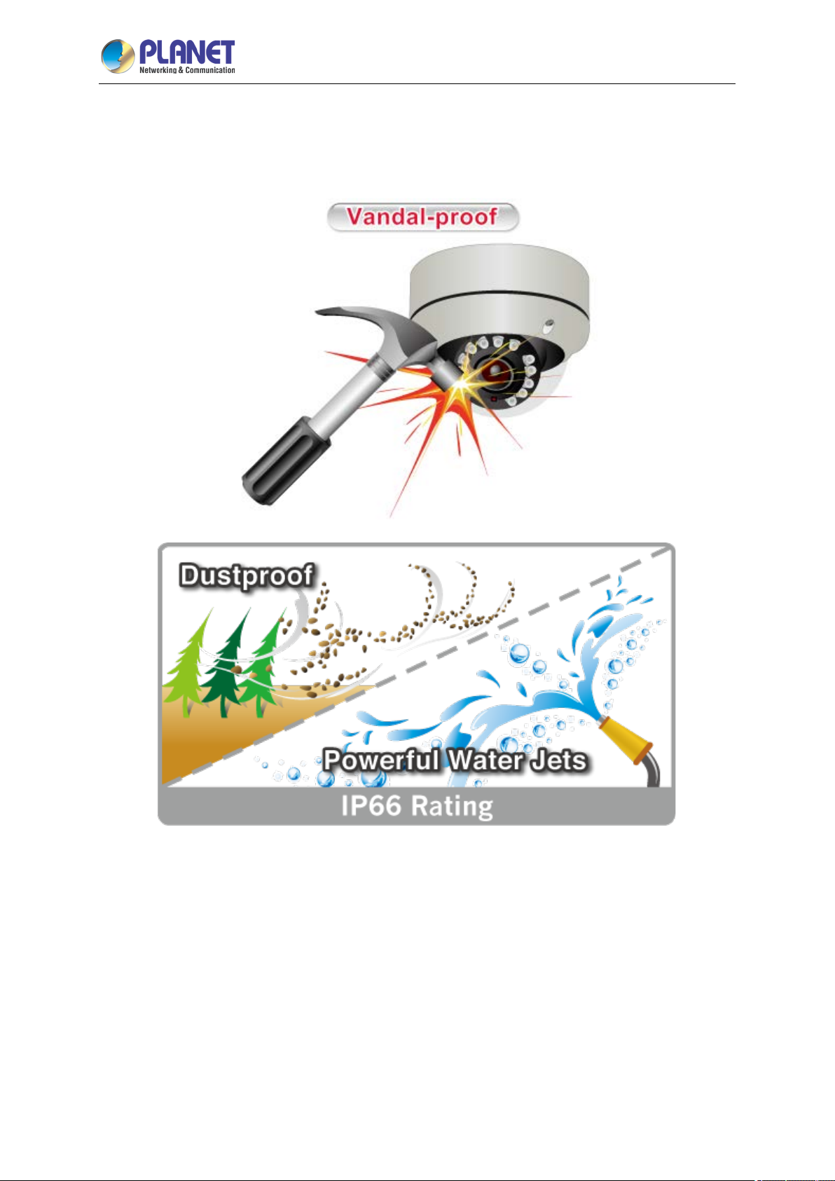
With the IK10-rated vandal-proof metal casing and water-repellent glass, the ICA-E6265 ensures
resistance against impacts. Moreover, rain, water jets and dus t are not able to seep into its body,
making the ICA-E6265 a reliable unit. It definitely operates under any extreme weather conditions.
Page 11
2 Mega-pixel IR PoE Plus Speed Dome IP Camera
11
ICA-E6265
Flexible Installation and Power Functionality
The ICA-E6265, adopting the IEEE 802.3at high Power over Ethernet technology, can be powered
from a P oE injector via the network, which eliminates the need for power cables and reduces
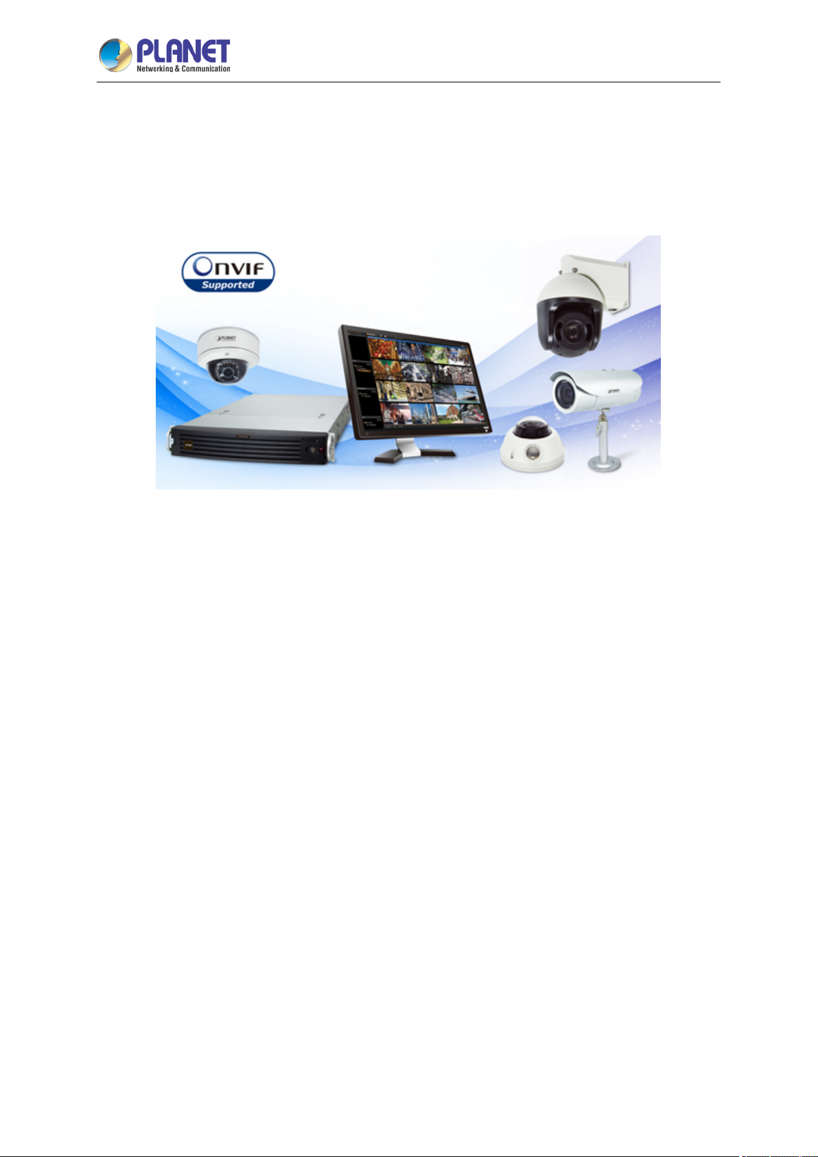
installation costs. In addition, the ICA-E6265 is ONVIF-compliant and therefore interoperable with
other brands in the market, greatly supporting users to integrate with their existing surveillance
network.
Page 12

2 Mega-pixel IR PoE Plus Speed Dome IP Camera
12
1.3 Features
Camera
1/2.8'' 2 mega-pixel progressive scan CMOS sensor
Auto-focal 4.7~148.5 mm, auto-iris lens
0.05 lux minimum illumination at F1.6
Maximum resolution 1920 x 1080
33 x 10 zooming (33x optical, 10x digital) adjustment
Endless 360-degree pan
Auto white balance and auto electronic shutter time (1/5 ~ 1/32k sec)
Built-in 8 adaptive IR illuminators, effective up to 150 meters
Removable IR-cut filter for Day & Night function
Video and Audio
ICA-E6265
H.264/MJPEG video compression
Simultaneous multi-stream support
H.264 high profile, main profile and baseline
Max. resolution of 2 mega-pixel at 60fps
Automatic object detection and tracking
3DNR to improve picture quality at low lux
Digital image stabilizer supported
True WDR enhancement function strengthens visibility under extremely bright or dark
environments
Two-way audio support with enhanced audio quality
Network and Configuration
Compliant with IEEE 802.3at high PoE interface for flexible deployment
Supports both IPv6 and IPv4 protocols
R T S P, U P n P, Bonjour and HTTPS protocols selectable
Easy Installation and Management
ONVIF compliant for interoperability
IK10 and IP66 rating
Micro SD card slot for video recording
Digital Input/Output for integration with sensors and alarms
Fan and heater with fully automatic intelligent control
Cam viewer E-series software supported – CV7L, CV7-VA , CV 7-LP and mobile app
Page 13
2 Mega-pixel IR PoE Plus Speed Dome IP Camera
13
Camera
Image Device
1/2.8'' 2 mega-pixel progressive scan CMOS Sensor
Color: 0.05 lux @ F1.6 (30 IRE, 2400°K)
B/W: 0 lux (IR on)
Effective Pixels
1920 x 1080 pixels
Horizontal Resolution
1800 TVL
Electronic Shutter
1/5~1/32000 sec.
S/N Ratio
56dB
Pan/Tilt/Zoom
Image
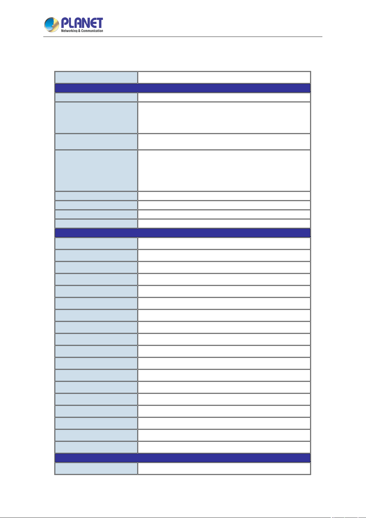
1.4 Product Specifications
ICA-E6265
Model
Lens
Min. Illuminator
IR Illumination LED
Optical Zoom
Digital Zoom
ICA-E6265
Auto-focal 4.5~148.5 mm/F1.6~5.0, auto-iris
Mechanical IR-cut filter
Angle of view: Horizontal: 3~69.3 degrees
8 adaptive IR 850nm LEDs
Built-in IR illuminators, effective up to 150 meters* (0 lux, 30
IRE, Gain 255, Auto shutter mode)
*The IR distance is based on the environment.
33x
10x
Tele to Wide Speed
Pan
Tilt
Manual Panning Speed
Manual Tilting Speed
Preset Points
Preset Tours
Preset Panning Accuracy
Preset Tilting Accuracy
Preset Panning Speed
Preset Tilting Speed
Resume after Power loss
Auto scan
Protocol
Absolute Position
2.7 sec
360 degrees (endless)
-20 ~ 200 degrees
3.2 ~ 72 degrees/sec.
1.6 ~ 36 degrees/sec.
256
10
0.265 degrees
0.265 degrees
0.1~300 degrees/sec.
0.1~150 degrees/sec.
Yes
Yes
Sony VISCA, Pelco D, Pelco P
Yes
PTZ Auto Tracking
Video Encoder
Yes
H.264/MJPEG
Page 14
14
Audio
Network and Configuration
System Integration
General
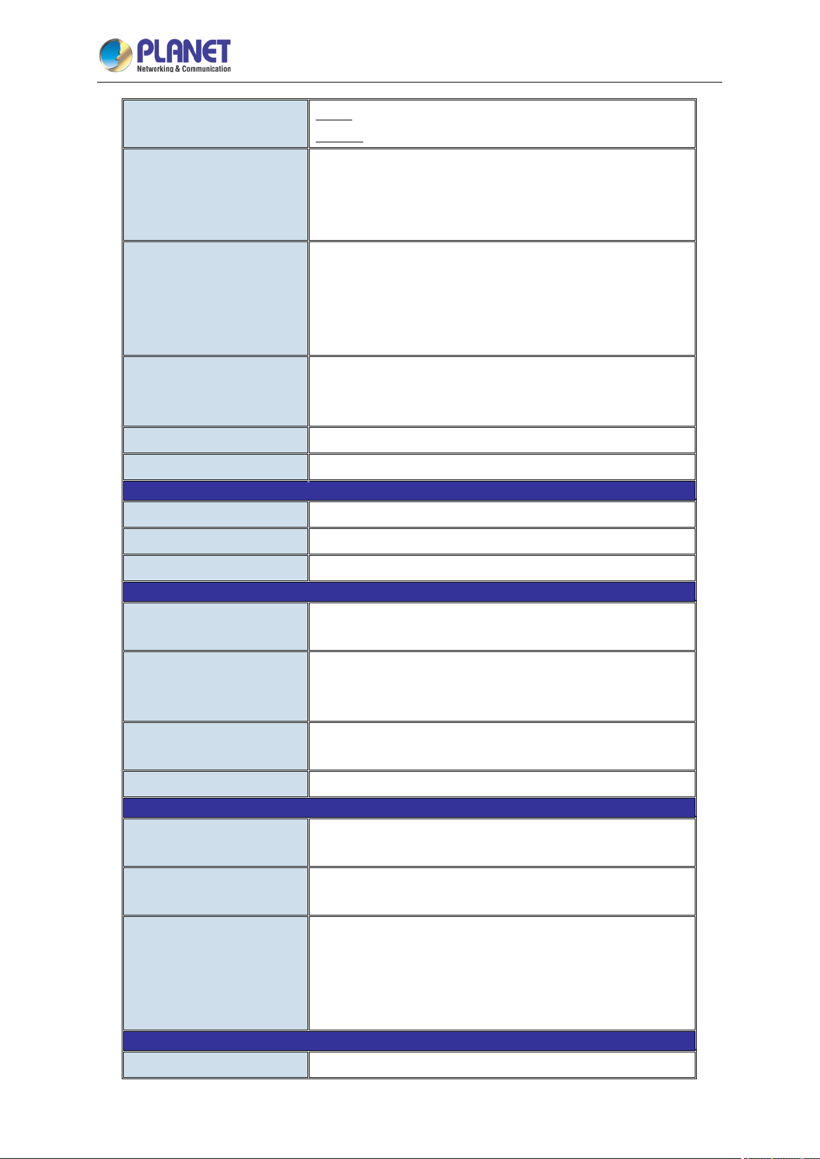
Video Profile
Frame Rate
Image Setting
2 Mega-pixel IR PoE Plus Speed Dome IP Camera
ICA-E6265
H.264: 1920 x 1080, 1280 x 720, 640 x 480, 320 x 240
MJPEG: 1920 x 1080, 1280 x 720, 640 x 480, 320 x 240
1920 x 1080 at up to 60fps
1280 x 720 at up to 60fps
640 x 480 at up to 30fps
320 x 240 at up to 30fps
Video flipping/video mirroring, brightness, contrast, automatic
gain control, 2D+3D digital noise reduction, edge
enhancement, true WDR (145dB), exposure, white balance
(automatic, manual or hold), OSD, privacy mask (20 regions),
digital image stabilizer
Streaming
Bit Rate
Text Overlay
Audio Streaming
Compression
Audio Input/Audio-Out
Network Standard
Protocol and Service
Security
Simultaneous triple streams based on three configurations
Controllable frame rate and bandwidth
Constant and variable bit rate
128 Kbps - 12 Mbps (per stream)
User defined text on video
Two-way audio
PCM, G. 7 11-Alaw, G.711-Ulaw
Cable with 3.5mm phone jack
IEEE 802.3 10BASE-T
IEEE 802.3u 100BASE-TX
TCP, UDP, HTTP, HTTPS, DHCP, PPPoE, RTP, RTSP, IPv6,
DNS, PLANET DDNS, PLANET Easy DDNS, NTP, ICMP,
A R P, I G M P, S M T P, F T P, U P n P, S N M P, B o nj o u r
Password protection, IP address filtering, HTTPS encryption,
anonymous login, 802.1X network access control
Users
Application Programming
Interface
Alarm Triggering
Alarm Events
Power Supply
10 simultaneous unicast users
Software Development Kit (SDK) available; ONVIF compliant
Video motion detection (10 regions), tamper, shock detection,
sound detection and external input
Notify control center; go to PTZ preset point or preset tour,
change camera settings; command other devices; e-mail
notification with snapshots; save video or snapshot to local
storage; upload video and snapshot to FTP server; activate
external device through digital output
High PoE (IEEE 802.3at)
Page 15
15
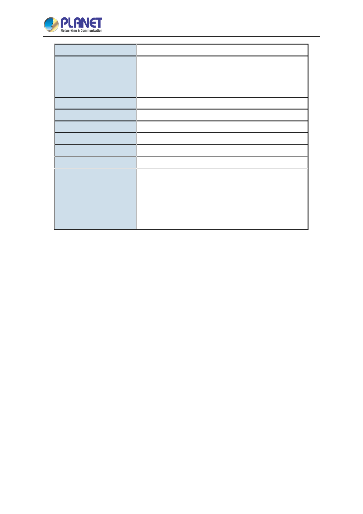
Power Consumption
2 Mega-pixel IR PoE Plus Speed Dome IP Camera
ICA-E6265
AC 24V, 3A
PoE: 50W (with IR and heater)*
AC 24V: 62W (with IR and heater)*
*When IR or heater is on, it is recommended to power on the
camera by the 60-watt ultra PoE injector included in the package.
Housing
Operating Temperature
Operating Humidity
Weight
Dimensions (Φ x H)
Emission
Connectors
IK10 and IP66 rating
-40 ~ 55 degrees C (within 30mins)
10 ~ 85% (non-condensing)
3112g
170 x 260 mm
CE, FCC
10/100Mbps Ethernet, RJ45
Micro SDHC card slot (max. 32GB, class 10)
Terminal block for 4 alarm inputs and 2 outputs
External mic input
Audio out
AC power jack
Page 16
2 Mega-pixel IR PoE Plus Speed Dome IP Camera
16
Reset Button
Micro SD Card Slot
Power LED
Chapter 2. Hardware Interface
2.1 Physical Descriptions
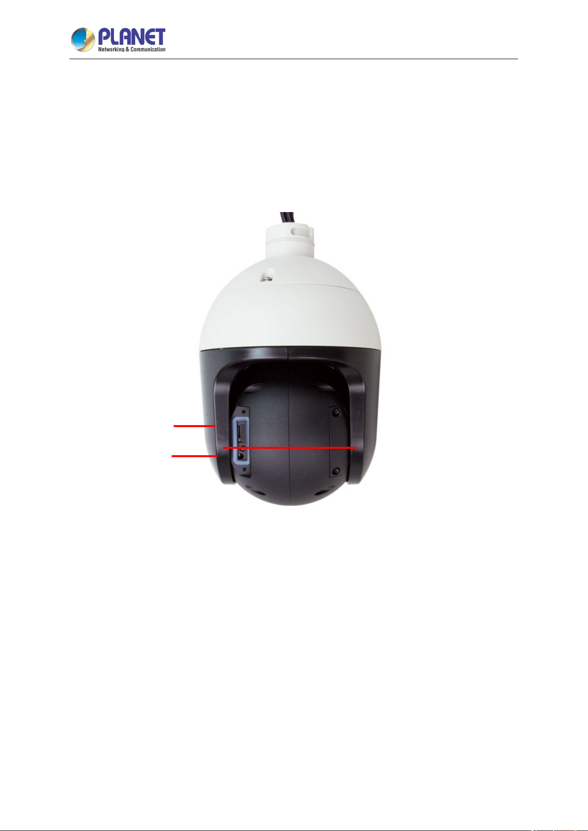
2.1.1 Identification of ICA-E6265 Rear Panel and Connectors
ICA-E6265
1. Memory Card Slot: Supports microSDHC cards.
Insert a memory card (not included) into this slot for local recording purposes.
2. Reset Button: Use the Reset Button to restore the camera to factory default settings. To do the
reset, press and hold the Reset button for at least 5 seconds or until the Power LED lights off. The
camera will reboot and restore to factory default settings.
3. Power LED
The Power LED lights up when the camera is connected to the power source.
Page 17
17
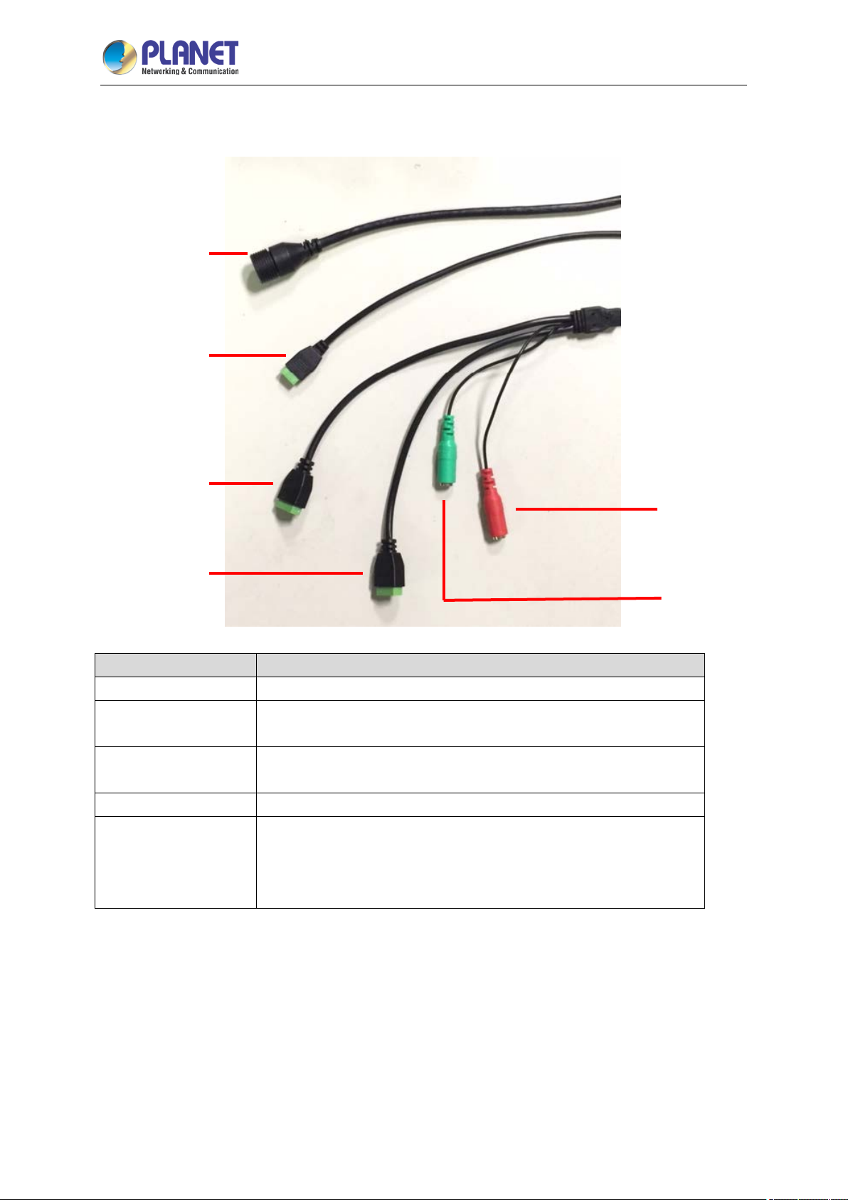
2.1.2 Identification of ICA-E6265 Connectors
Ethernet Port
24V AC Power Input
2 Mega-pixel IR PoE Plus Speed Dome IP Camera
ICA-E6265
Digital Input/Output
Digital Input/Output
Connectors Description
Ethernet Port
24V AC Power Input
Audio Input
Audio Output
Digital Input/Output
Audio Input
Audio Output
Connect to a network using a standard Ethernet cable.
This jack connects to the 24V AC power adapter and power cord to
supply power to the camera.
Connect to audio input devices, such as a microphone with built-in
amplifier, etc.
Connect to audio output devices, such as a speaker, etc.
Connect to digital input or output devices, such as an alarm trigger,
panic button, etc. Digital Input (DI) and Digital Output (DO) devices
are used in applications like motion detection, event triggering, alarm
notifications, etc.
Page 18
2 Mega-pixel IR PoE Plus Speed Dome IP Camera
18
2.2 Hardware Installation
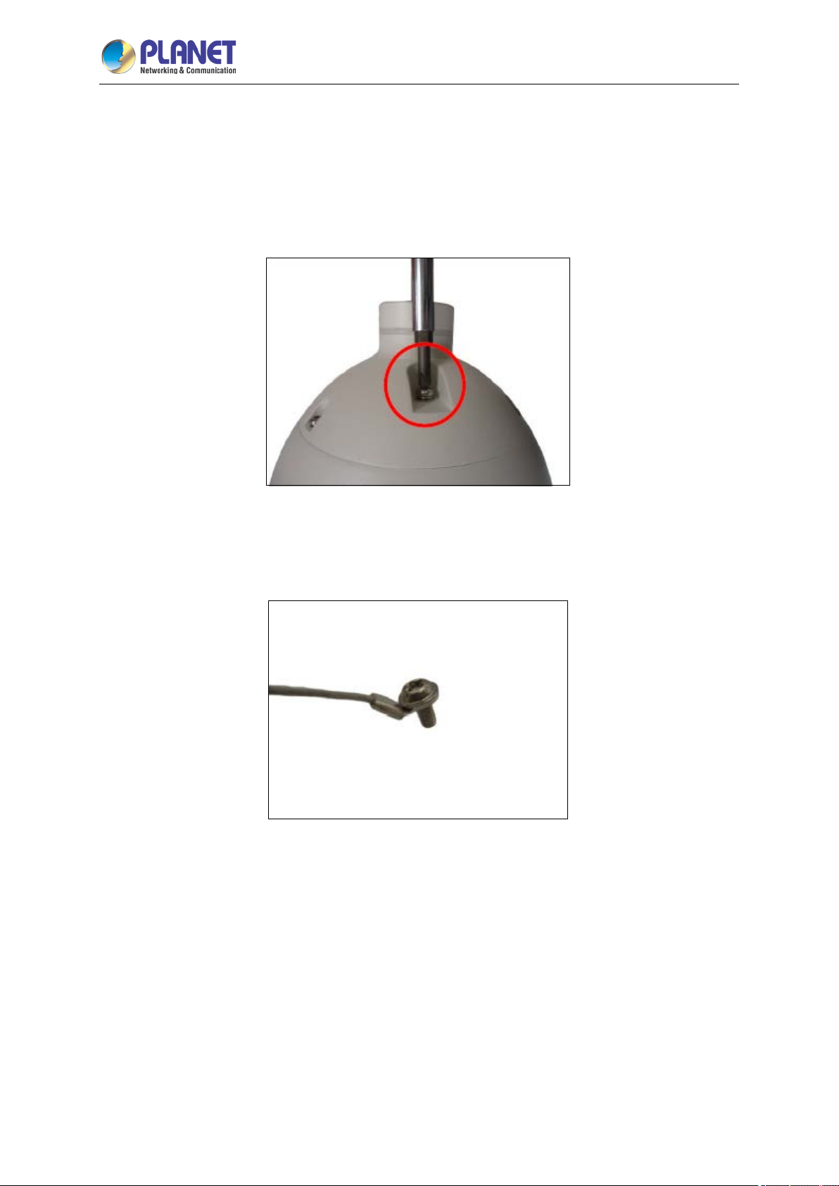
2.2.1 Removing the Set Screw
Locate and remove the set screw on the top of the camera.
ICA-E6265
2.2.2 Inserting the Set Screw to the Safety Strap
Insert the removed set screw into the smaller hole of the safety strap.
Page 19
2 Mega-pixel IR PoE Plus Speed Dome IP Camera
19
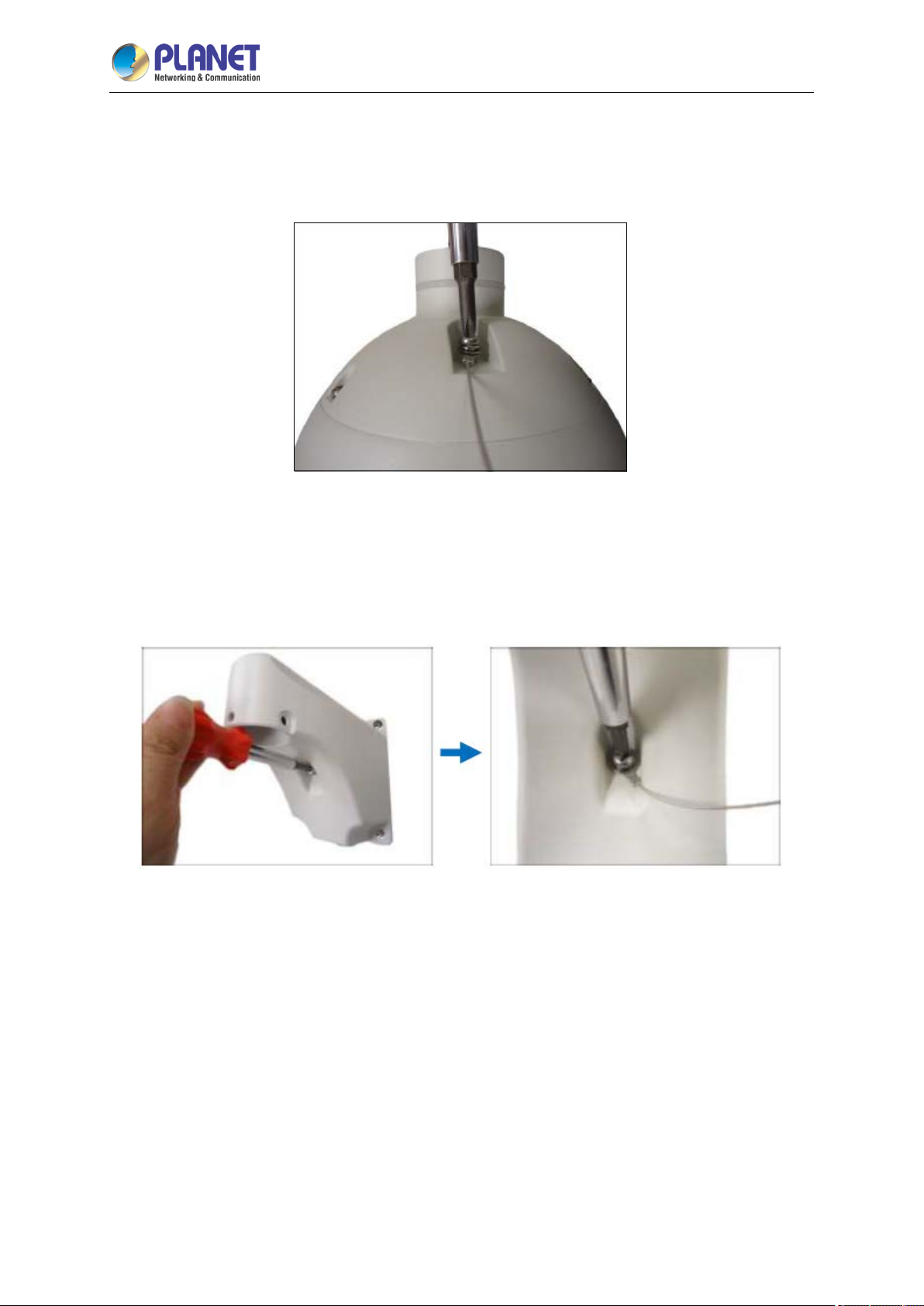
2.2.3 Attaching the Set Screw back
Attach the set screw back to the camera.
ICA-E6265
2.2.4 Installing the Mounting Solution
Install the mounting accessory on wall or ceiling.
Page 20
2 Mega-pixel IR PoE Plus Speed Dome IP Camera
20
ICA-E6265
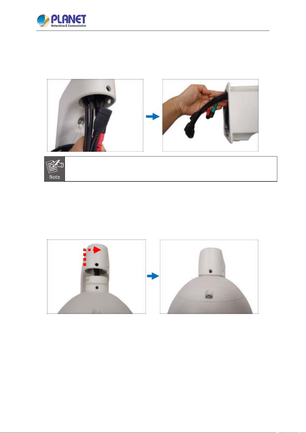
2.2.5 Inserting the Cable
Insert the camera cables through the mounting accessory (e.g. PTZ wall mount, straight tube,
extension tube, etc.) and through a hole in the wall or ceiling.
The camera itself is waterproof, but the cable connections are not. If the cable connections
are exposed outdoors, make sure to shield or adapt proper waterproofing methods.
2.2.6 Mounting the Camera
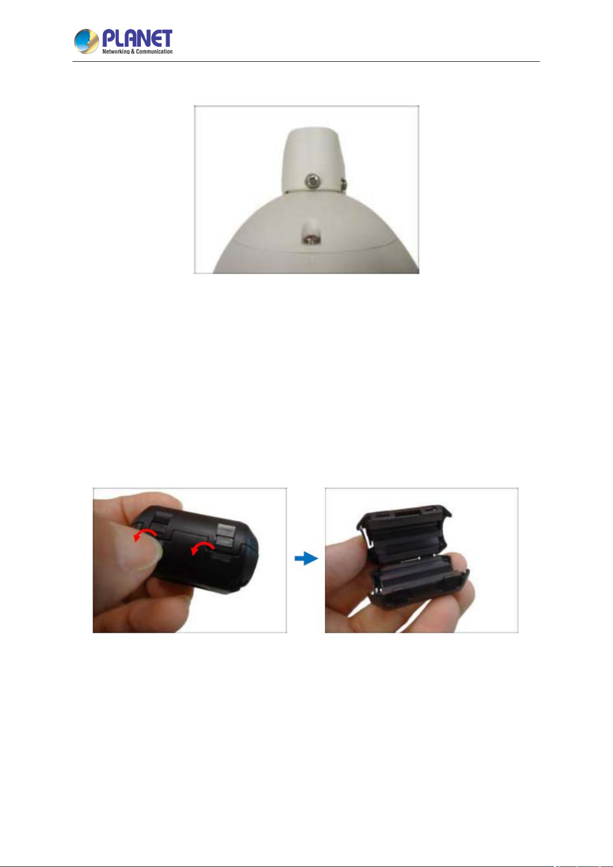
Align the gap on the camera to the tab inside the mounting solution and insert the camera through the
mounting tube.
Page 21
2 Mega-pixel IR PoE Plus Speed Dome IP Camera
21
Attach the screws included in the camera package to secure the camera.
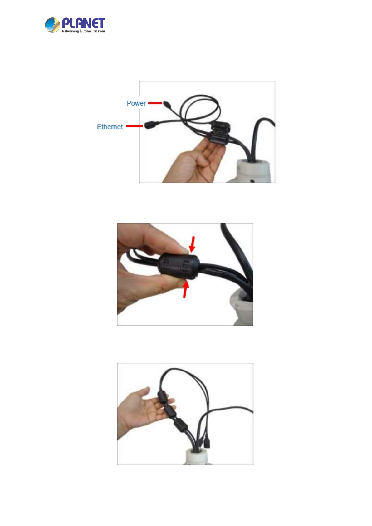
2.2.7 Attaching Ferrite Cores and Connecting Cables
ICA-E6265
The bundled ferrite cores should be attached to the camera cable to comply with EMC standards
either before or after mounting the camera depending on how the camera will be mounted and the type
of accessories that will be used (check the mounting accessory itself to validate if the ferrite core
passes through its hole before mounting). The ferrite cores are used to suppress electromagnetic
interference (EMI) from electronic devices, including this camera, which may affect one another.
(1) Unsnap and open the bundled ferrite core.
Page 22
2 Mega-pixel IR PoE Plus Speed Dome IP Camera
22
ICA-E6265
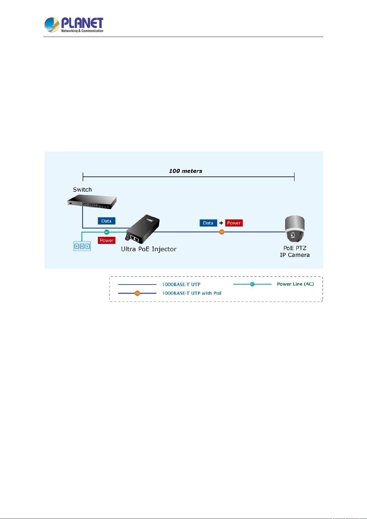
(2) Insert the Ethernet and 24V AC power cables in the ferrite core as close to the camera as
possible.
(3) Snap the ferrite core to secure it on the cable.
(4) Repeat steps 1 to 3 to attach the other two bundled ferrite cores on the cable close to each other.
Page 23
2 Mega-pixel IR PoE Plus Speed Dome IP Camera
23
ICA-E6265
2.2.8 Powering on the Camera via 60-watt Ultra PoE Injector
(1) Connect the AC power cord to “AC slot” of ultra PoE injector; the “POWER” LED will be on
steadily.
(2) Connect an Ethernet cable (not included in the package) to the port (PoE) of the camera. It is
recommended to use exterior-grade Ethernet cable that is already waterproof.
(3) Connect another end of the Ethernet cable to ultra PoE injector. Once ultra PoE injector detects
the existence of an IEEE 802.3at/802.3af device, the ACTIVE LED indicator will be on steadily to
show it is providing power.
2.2.9 Connecting the Camera to Network
Connect an Ethernet cable (not included in the package) from switch/workstation to “LAN” port of ultra
PoE injector.
Page 24
2 Mega-pixel IR PoE Plus Speed Dome IP Camera
24
ICA-E6265
2.3 Initial Utility Installation
This chapter shows how to quickly set up your H.264 camera. The camera is with the default settings.
However, to help you find the networked camera quickly the windows utility PLANET Smart Discovery
Lite can search the cameras in the network that will help you to configure some basic settings before
you start advanced management and monitoring.
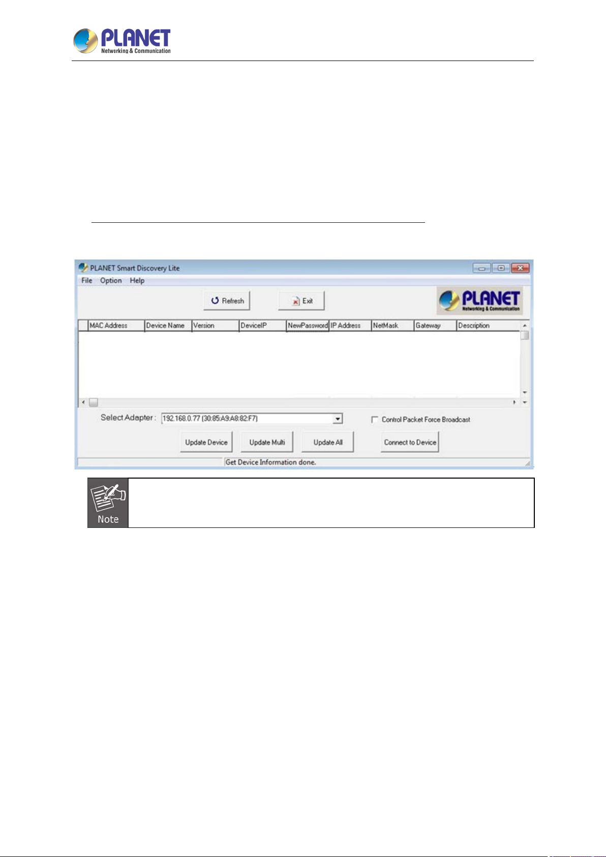
Step 1 Go to PLANET website and download the Smart Discovery Lite utility.
http://planet.com.tw/en/support/download.php?view=8184&key=ICA-E#list
Step 2 Run Smart Discovery Lite utility to start searching for cameras.
If there are two LAN cards or above in the same administrator PC, choose a different
LAN card by using the “Select Adapter” tool.
Page 25
2 Mega-pixel IR PoE Plus Speed Dome IP Camera
25
ICA-E6265
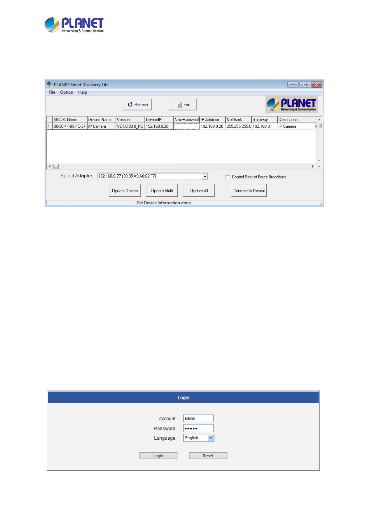
Step 3 Press the “Refresh” button to see the currently-connected devices in the discovery list as
the screen shows. If there is no DHCP server in the network, the default IP of camera is
192.168.0.20.
(1) This utility shows all necessary information from the devices, such as MAC address, device mame,
firmware version and device IP subnet address. You can also assign a new password, IP subnet
address and description to the devices.
(2) After setup is completed, press the “Update Device”, “Update Multi” or “Update All” button to
take affect. The definitions of the 3 buttons above are shown below:
Update Device: Use the current setting on one single device.
Update Multi: Use the current setting on choose multi-devices.
Update All: Use the current setting on whole devices in the list.
The same functions mentioned above can also be found in the “Option” tools bar.
To click the “Control Packet Force Broadcast” function, it allows you to assign a new setting
value to the Web Smart Switch under a different IP subnet address.
(3) Press the “Connect to Device” button and the Web login screen will appear.
(4) Press the “Exit” button to shut down the planet Smart Discovery Utility.
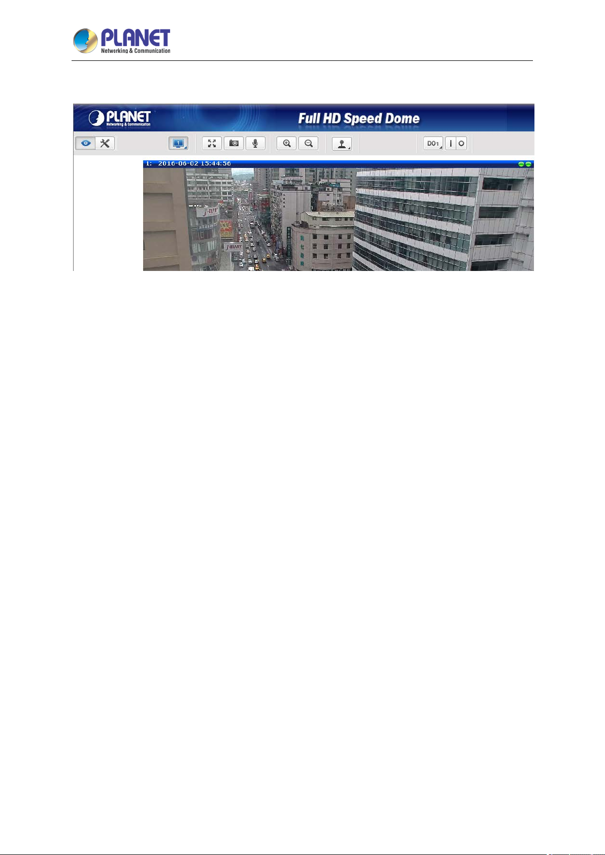
Step 4 Then, please key-in the default User Name “admin” and Password “admin” in the following
window.
Page 26
2 Mega-pixel IR PoE Plus Speed Dome IP Camera
26
Step 5 The following web page will be displayed.
ICA-E6265
Page 27
2 Mega-pixel IR PoE Plus Speed Dome IP Camera
27
ICA-E6265
2.4 Using UPnP of Windows XP or 7
2.4.1 Windows XP
UPnP™ is short for Universal Plug and Play, which is a networking architecture that provides
compatibility among networking equipment, software, and peripherals. This device is an UPnP enabled
device. If the operating system, Windows XP, of your PC is UPnP enabled, the device will be very easy
to configure. Use the following steps to enable UPnP settings only if your operating system of PC is
running Windows XP.
Please note that MS Windows 2000 does not support UPnP feature.
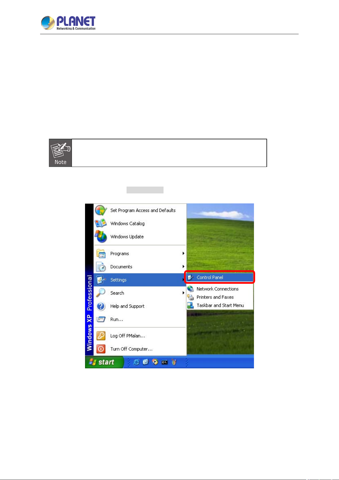
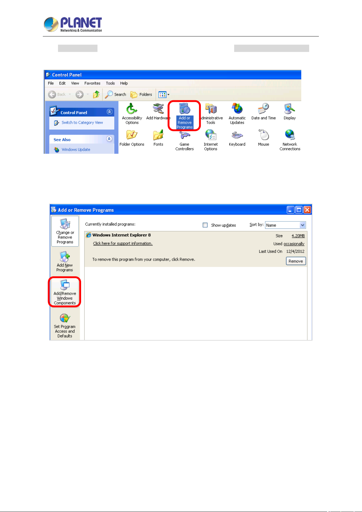
Go to Start > Settings, and Click Control Panel.
Page 28
2 Mega-pixel IR PoE Plus Speed Dome IP Camera
28
ICA-E6265
The “Control Panel” will be displayed on the screen and double-click “Add or Remove Programs” to
continue.
The “Add or Remove Programs” will be displayed on the screen and click Add/Remove Widows
Components to continue.
Page 29
2 Mega-pixel IR PoE Plus Speed Dome IP Camera
29
ICA-E6265
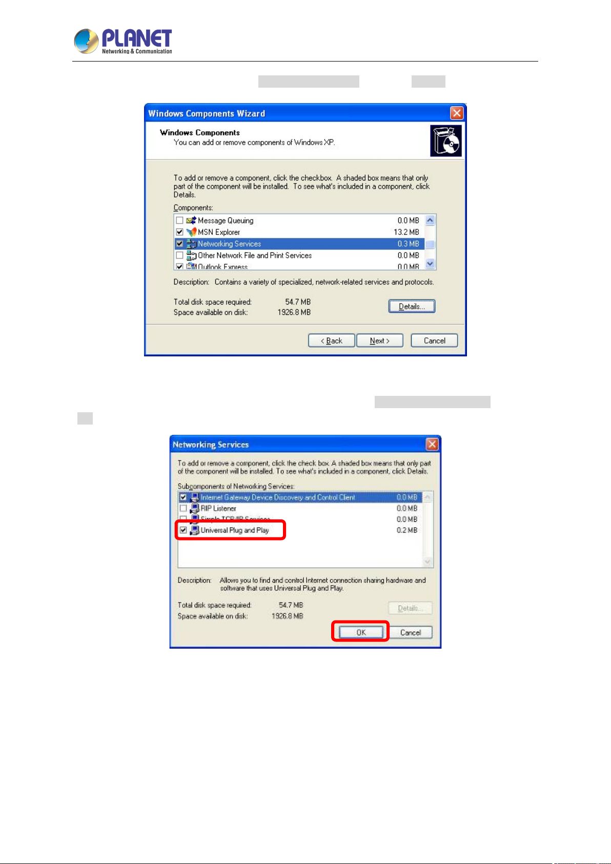
The following screen will appear; select “Networking Services” and click “Details” to continue.
The “Networking Services” will be displayed on the screen; select “Universal Plug and Play” and click
“OK” to continue.
Page 30
30
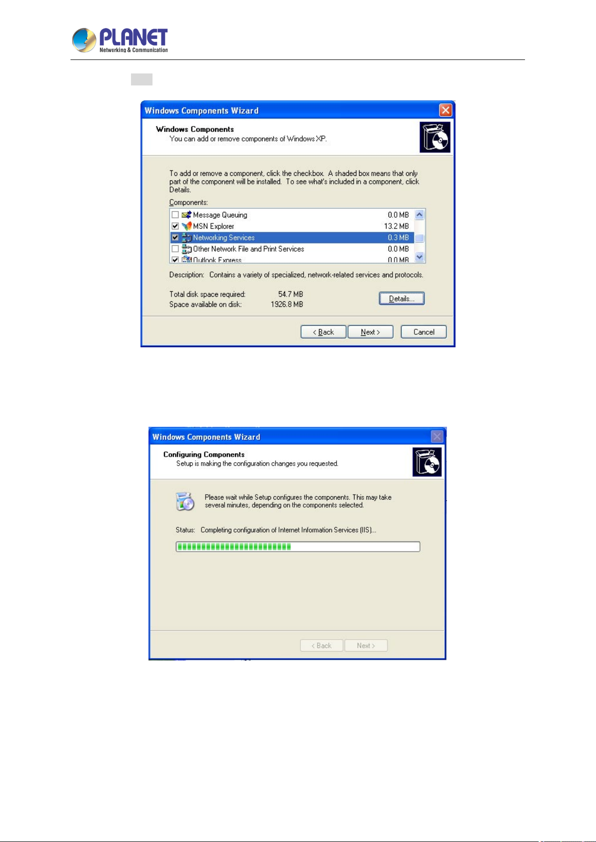
Please click “Next” to continue.
2 Mega-pixel IR PoE Plus Speed Dome IP Camera
ICA-E6265
The program will start installing the UPnP automatically. You will see the pop-up screen as shown
below. Please wait while Setup configures the components.
Page 31
2 Mega-pixel IR PoE Plus Speed Dome IP Camera
31
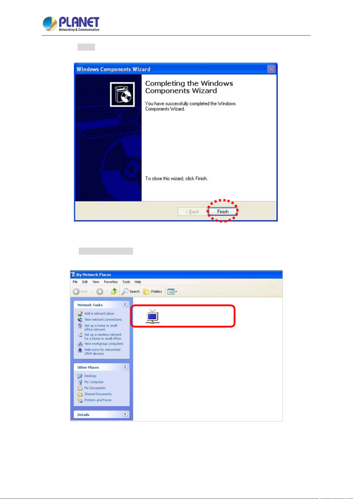
Please click “Finish” to complete the UPnP installation
ICA-E6265
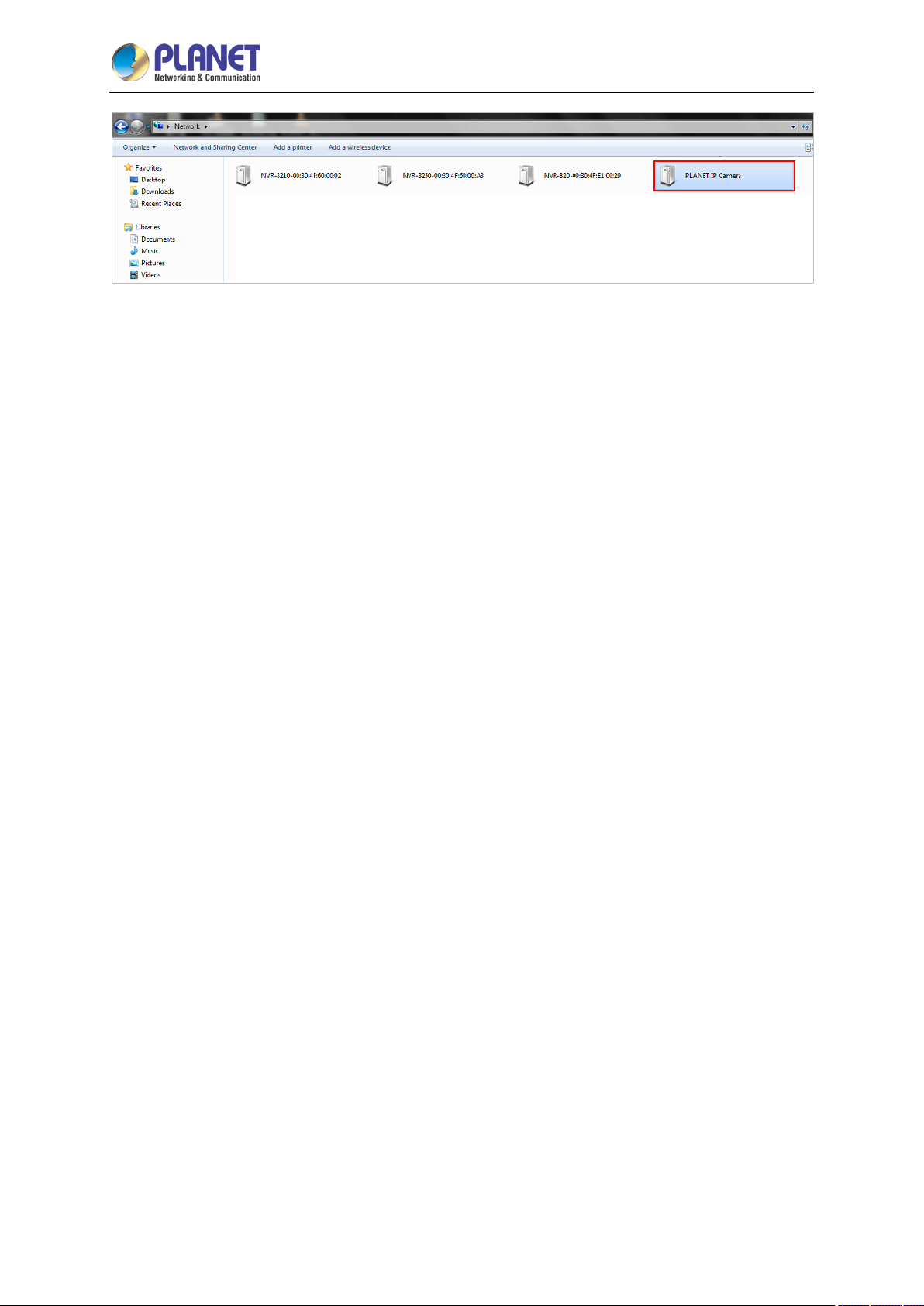
Double-click “My Network Places” on the desktop; the “My Network Places” will be displayed on the
screen and double-click the UPnP icon with IP camera to view your device in an Internet browser.
PLANET IP Camera
Page 32
2 Mega-pixel IR PoE Plus Speed Dome IP Camera
32
ICA-E6265
2.4.2 Windows 7
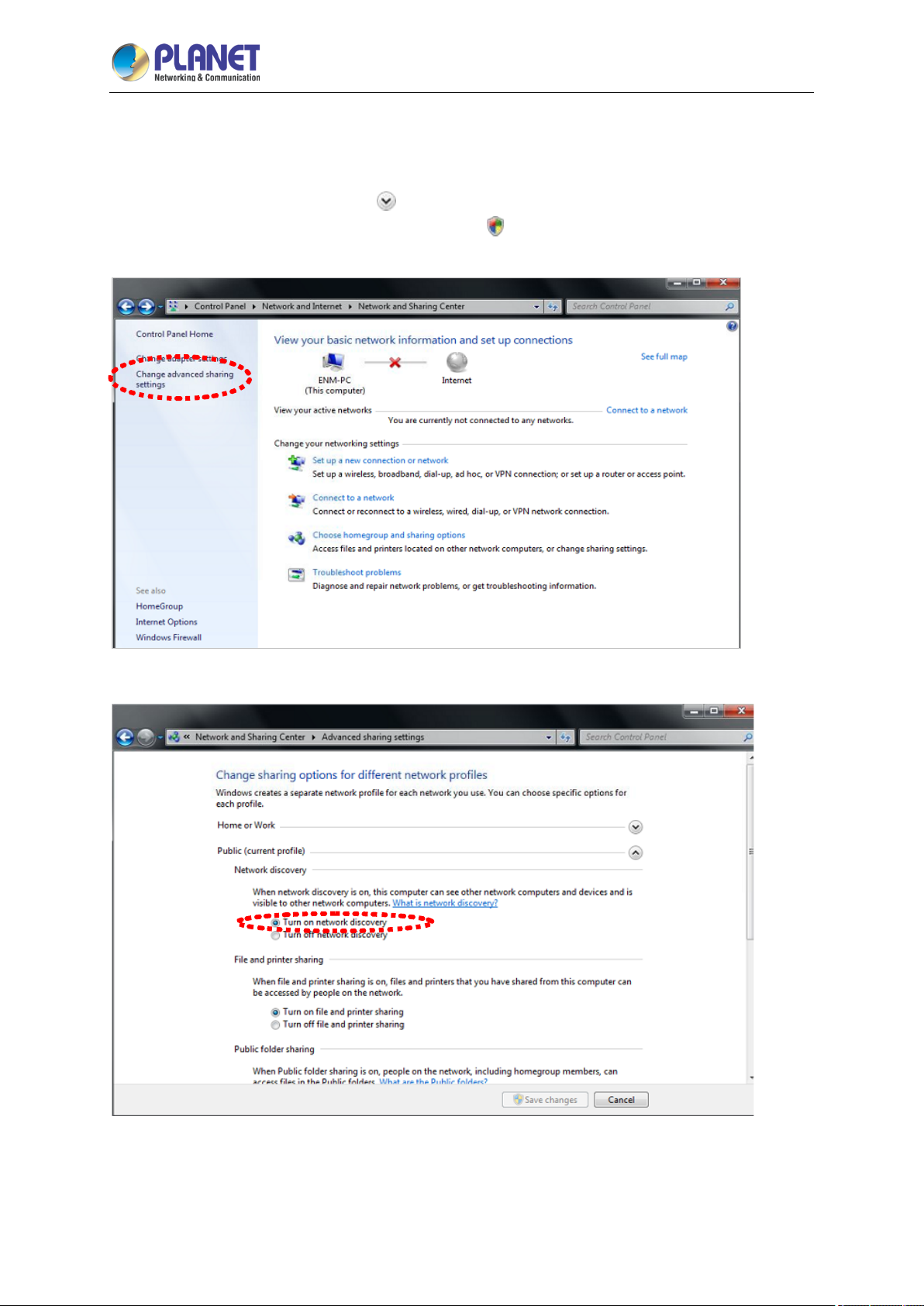
Go to Start > Control Panel > Network and Internet > Network and Sharing Center. If network
discovery is off, click the arrow button
Click Turn on network discovery, and then click Apply.
password or confirmation, type the password or provide confirmation.
to expand the section.
If you are prompted for an administrator
Page 33
2 Mega-pixel IR PoE Plus Speed Dome IP Camera
33
ICA-E6265
Page 34
2 Mega-pixel IR PoE Plus Speed Dome IP Camera
34
2 3
5
7 8
ICA-E6265
2.5 Setting Up ActiveX for IP Camera
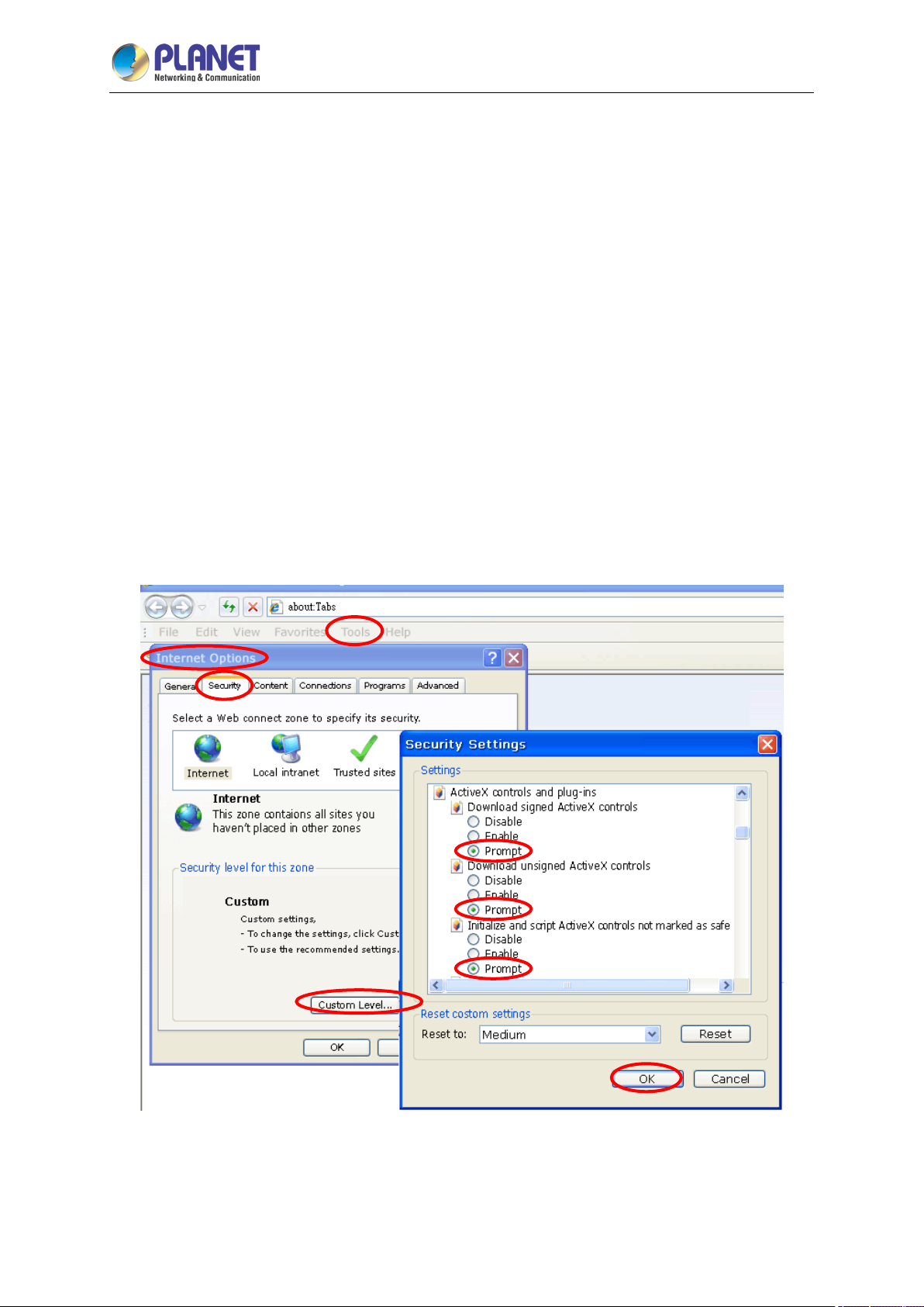
The IP camera web pages communicate with the IP camera using an ActiveX control. The ActiveX
control must be downloaded from the IP camera and installed on your PC. Your Internet Explorer
security settings must allow for the web page to work correctly. To use the IP camera, user must set up
his IE browser as follows:
2.5.1 Internet Explorer 6 for Windows XP
From your IE browse “Tools” “Internet Options…” “Security” “Custom Level…”, please set
up your “Settings” as follows:
Set the first 3 items
• Download the signed ActiveX controls
• Download the unsigned ActiveX controls
• Initialize and script the ActiveX controls not masked as safe to Prompt
1
6
4
Page 35
2 Mega-pixel IR PoE Plus Speed Dome IP Camera
35
ICA-E6265
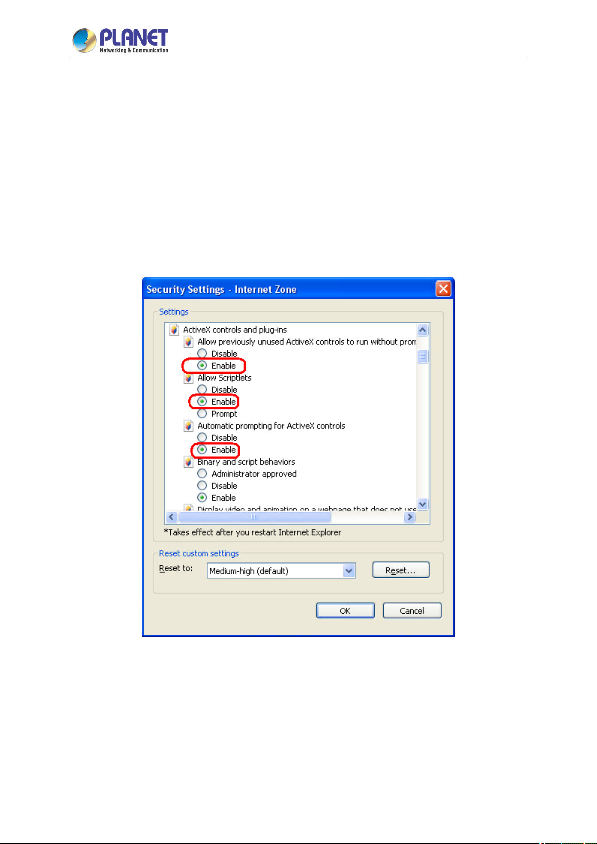
2.5.2 Internet Explorer 7 for Windows XP
From your IE browser “Tools” “Internet Options…” “Security” “Custom Level…”, please set
up your “Settings” as follows:
Set the first 3 items
• Allow previously unused ActiveX control to run…
• Allow Scriptlets
• Automatic prompting for ActiveX controls
By now, you have finished your entire PC configuration for IP camera.
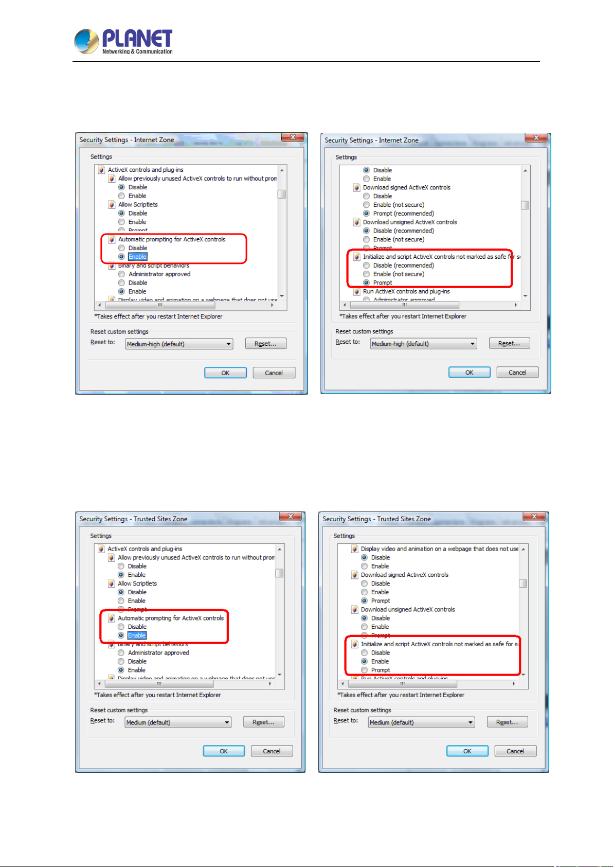
2.5.3 Internet Explorer 7 for Windows Vista
From your IE browser “Tools” “Internet Options…” “Security” “Internet” “Custom
Level…”, please set up your “Settings” as follows:
Page 36
2 Mega-pixel IR PoE Plus Speed Dome IP Camera
36
• Enable “Automatic prompting for ActiveX controls”
• Prompt “Initialize and script active controls not marked….”
ICA-E6265
From your IE browse “Tools” “Internet Options…” “Security” “Trusted Sites” “Custom
Level…”, please set up your “Settings” as follows:
• Enable “Automatic prompting for ActiveX controls”
• Prompt “Initialize and script active controls not marked….”
By now, you have finished your entire PC configuration for IP camera.
Page 37
2 Mega-pixel IR PoE Plus Speed Dome IP Camera
37
ICA-E6265
Chapter 3. Web-based Management
This chapter provides setup details of the IP camera’s web-based interface.
3.1 Introduction
The IP camera can be configured with your web browser. Before configuring, please make sure your
PC is under the same IP segment as IP camera.
3.2 Connecting to IP Camera
A. Use the following procedures to establish a connection from your PC to the IP camera.
B. Once the camera is connected, you can add the camera to your browser’s Favorites or Bookmarks.
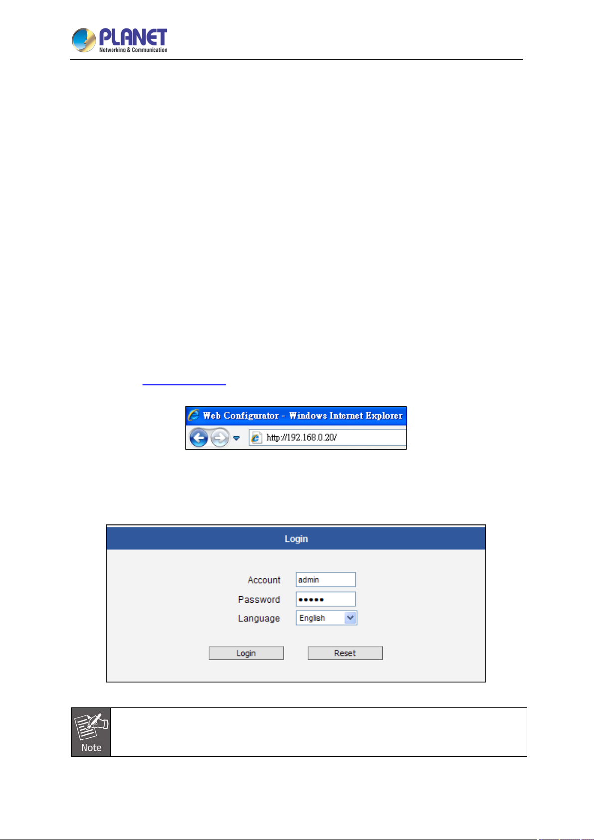
Start the web browser on the computer and type the IP address of the camera.
The default IP: “
The login window of IP camera will appear,
Default login username and password are both admin.
http://192.168.0.20“
If the User Name and Password have been changed, please enter the new User Name and
Password here.
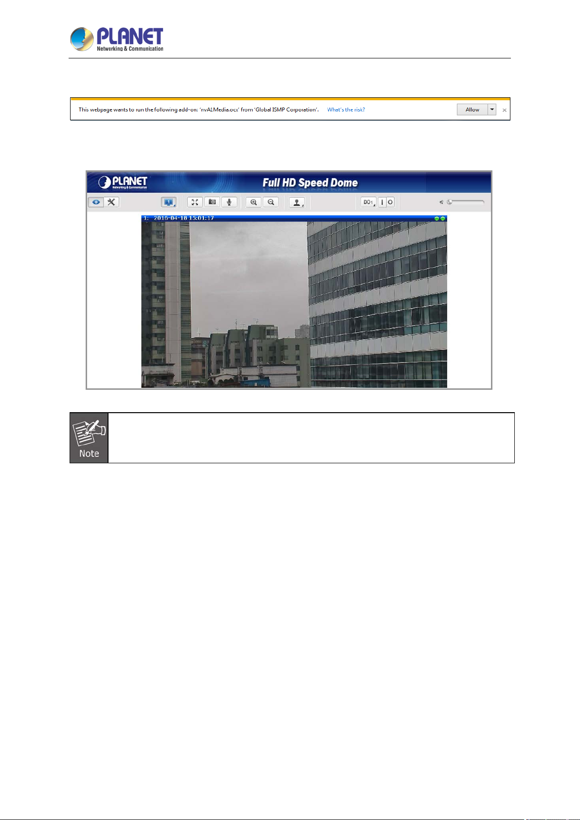
After logging on, you should see the following messages at the bottom of Internet Explorer:
Page 38
2 Mega-pixel IR PoE Plus Speed Dome IP Camera
38
When you see this message, click Allow to install the required ActiveX control.
After the ActiveX control is installed and run, the first image will be displayed.
ICA-E6265
If you log in to the camera as an ordinary user, setting function will be not available. If you log
in to the camera as the administrator, you can perform all the settings provided within the
device.
Page 39
2 Mega-pixel IR PoE Plus Speed Dome IP Camera
39
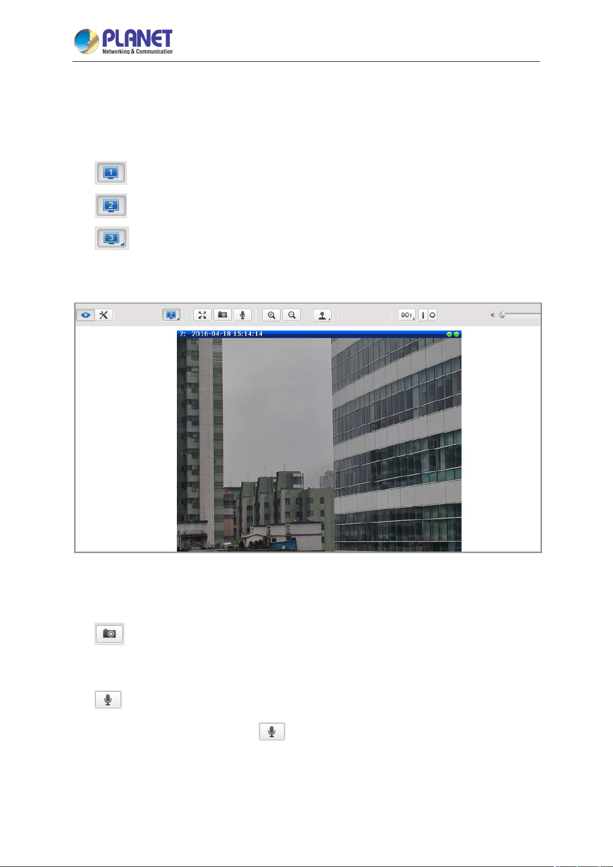
3.3 Live Viewing
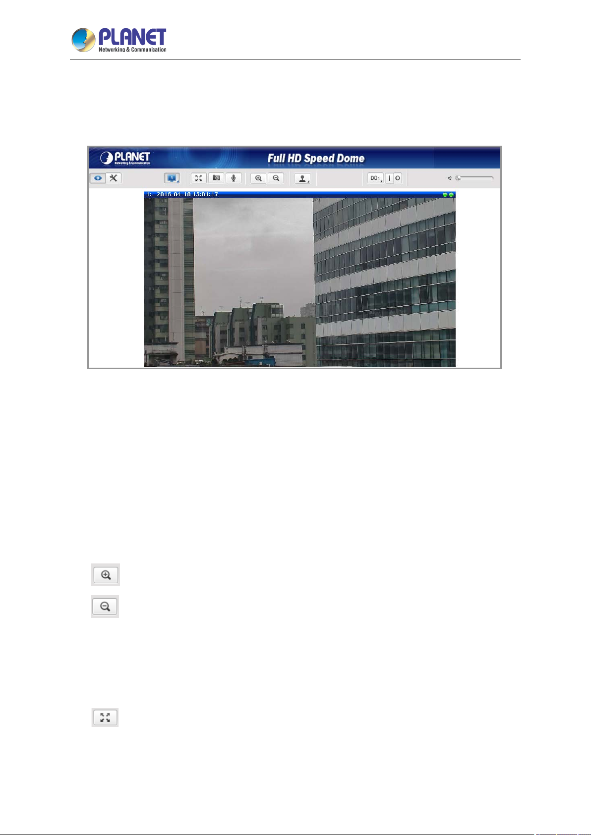
The live view will appear automatically with the video resolution of 1920 x 1080.
ICA-E6265
While being on the Live View page, the Live View icon appears as being pressed. If you leave the
Live View page, you can later return by pressing that button. The buttons shown on the Live View
page vary depending on the functions supported by the camera.
If the resolution of the PC’s monitor is bigger than the resolution of the live video, you will be able
to see the whole size of the video immediately. If not, you will only see part of the video at first and
you would have to use the scroll bars to see the rest of the video area. In order to see the whole
video on your display, you can temporarily re-scale the video to better fit your screen by pressing
the digital zoom buttons:
- Enlarge the video size digitally
- Reduce the video size digitally
Note: These digital zoom adjustments do not influence the actual video resolution of the camera.
Regardless of how large or small the video appears on the display after pressing the digital zoom
buttons, the actual video stream size of the camera is the same as before.
You can also digitally re-scale the video to fully match the size of your display with just 1 click:
- Full screen Mode
You may use ESC key from the keyboard to exit the full screen mode.
Page 40
2 Mega-pixel IR PoE Plus Speed Dome IP Camera
40
ICA-E6265
The cameras have the triple stream capability – Stream 1 is usually the high resolution stream
with the purpose of being recorded by NVR while Stream 2 and Stream 3 have lighter video
configuration for NVR live view purposes, to reduce the computing power of the NVR PC. Both
streams can be configured under Web Configurator’s Setup page. To see how each of the
streams looks like, there are quick buttons on the Live View page:
- Show Stream 1 video
- Show Stream 2 video
- Show Stream 3 video
When pressing the Stream 2 button, the Live View would look like this:
To capture the snapshots of the current live view, press the snapshot button. The snapshots are
saved in the Picture folder.
- Take a Snapshot
Cameras with audio function have the audio controls on the Live View page.
- Speak to Camera
To speak to the camera, press the
recorder, the audio will be recorded with the video stream. To adjust the volume level of the
speakers connected to the PC that runs the Web Management in order to hear the audio from the
camera’s microphone or line-in device, use the audio controls as shown below:
button. If the camera is connected to a network video
Page 41

2 Mega-pixel IR PoE Plus Speed Dome IP Camera
41
ICA-E6265
Audio muted:
Audio level adjusted to the maximum:
This volume control appears on the user interface only when the Audio-in function of the camera
has been “Enabled” under the Setup page.
The digital output controls appear on the Live View page of the cameras with digital input/output
function. The controls allow users to manually trigger a DO device.
- Select DO Port
Each DO port is controlled separately. For cameras with more than one DO port, select the DO
port and press
low. Consequently, setting the port to a high power level “activates” the DO device and setting the
port to a low power level “deactivates” the DO device. For example, if an alarm is set as DO1 and
is pressed, the alarm will continuously sound until is pressed to deactivate the device.
to set the output power level to high or to set the output power level to
Page 42

2 Mega-pixel IR PoE Plus Speed Dome IP Camera
42
ICA-E6265
3.4 PTZ Control Panel
For PTZ camera models, click the PTZ button on the Live View screen to display the PTZ
Control Panel. For PTZ cameras, the PTZ button can be one of the following:
This is the basic PTZ button. When the PTZ Control Panel is open, instead of using the pan/tilt controls,
move the mouse cursor over the Live View, the mouse cursor will turn into zoom in/out or directional
icons (e.g.
vi e w.
When the PTZ Control Panel is open, a red cross-hair (+) icon appears. Just like using a PC with a
mouse, users may draw a box using the mouse on the Live View area and the camera will zoom in on
the boxed area. Scroll down the mouse wheel to zoom out and scroll up to zoom in. To pan the camera,
double-click the mouse towards the direction you want to pan.
Joystick Mode:
/ / / / etc.). Click or drag the mouse to zoom in/out or pan/tilt the camera
Mouse Mode:
Page 43
43
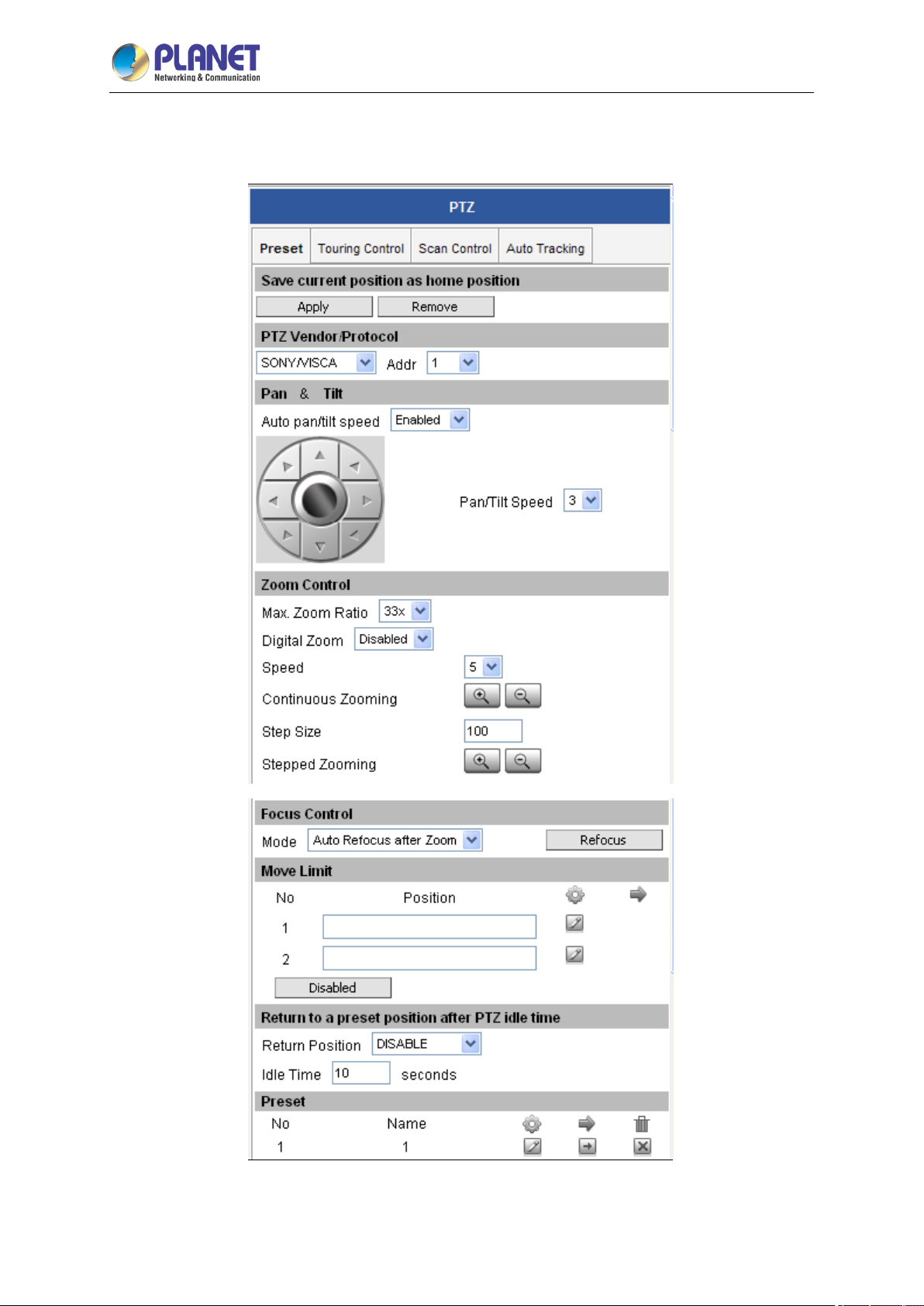
3.4.1 Preset
2 Mega-pixel IR PoE Plus Speed Dome IP Camera
ICA-E6265
Page 44
2 Mega-pixel IR PoE Plus Speed Dome IP Camera
44
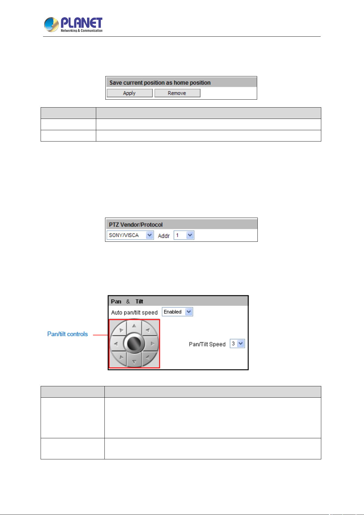
Set Home Position
Pan, tilt, and zoom on the area that you want to set as the home position.
Parameters Description
ICA-E6265
Apply
Remove
PTZ Vendor/Protocol
PLANET cameras and video management systems fully support the URL Command, a high level PT
command set. However, in case the cameras will be used with devices from third party vendors that
only support Serial Hex Command (low level PT command set), users must select the PTZ
Vendor/Protocol to use and its address. Otherwise, leave the default settings.
Pan & Tilt:
Click the pan/tilt controls to pan/tilt the PTZ camera.
Click the Apply button on the save current position as home position.
Click the Remove button to remove current home position.
Parameters Description
Auto Pan/Tilt
Speed
Pan/Tilt Speed
When “Enabled”, the camera automatically sets the pan/tilt speed according to
the zoom ratio and the selected pan/tilt speed while retaining the clarity and
quality of image even as the camera is panning or tilting. When “Disabled”, the
pan/tilt speed follows the value selected on the Pan/Tilt Speed field.
Select the desired pan/tilt speed. The bigger the number, the faster the speed
is.
Page 45
2 Mega-pixel IR PoE Plus Speed Dome IP Camera
45
While the PTZ Control Panel is open, instead of using the pan/tilt controls, move the mouse
cursor over the Live View. Click or drag the mouse to zoom in/out or pan/tilt the camera
vi e w.
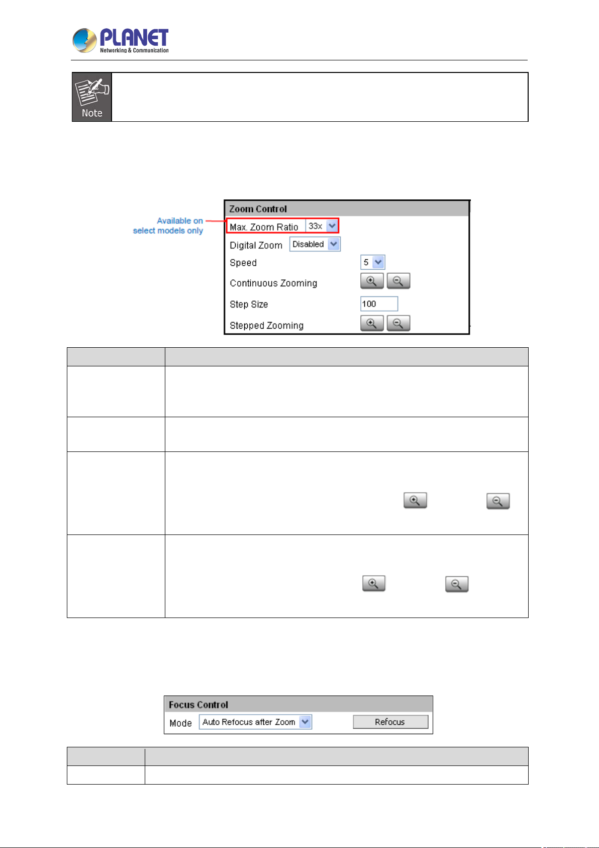
Zoom Control:
Zooming can be done continuously or by one click at a time.
ICA-E6265
Parameters Description
Max. Zoom Ratio
Digital Zoom
Zoom
Continuously
Zoom by Step
Zooming
Setting the maximum zoom ratio helps to ensure that focus is kept all
throughout the zoom in/out process. For other cameras with optical zoom lens,
setting the maximum zoom ratio can be done through the URL command.
When it is enabled, once the optical zoom reaches its maximum, the camera
continues to zoom in on the image using digital zoom.
On Zoom Control, select the Speed, wherein the bigger the number, the faster
the zoom speed will be.
Then click and hold the left mouse button to zoom in
When the mouse button is released, zooming stops.
On Zoom Control, enter the desired step size. Size is the amount of zoom scale
taken in each step.
Then click the left mouse button to zoom in
step is taken for each click.
or zoom out .
or zoom out . One zoom
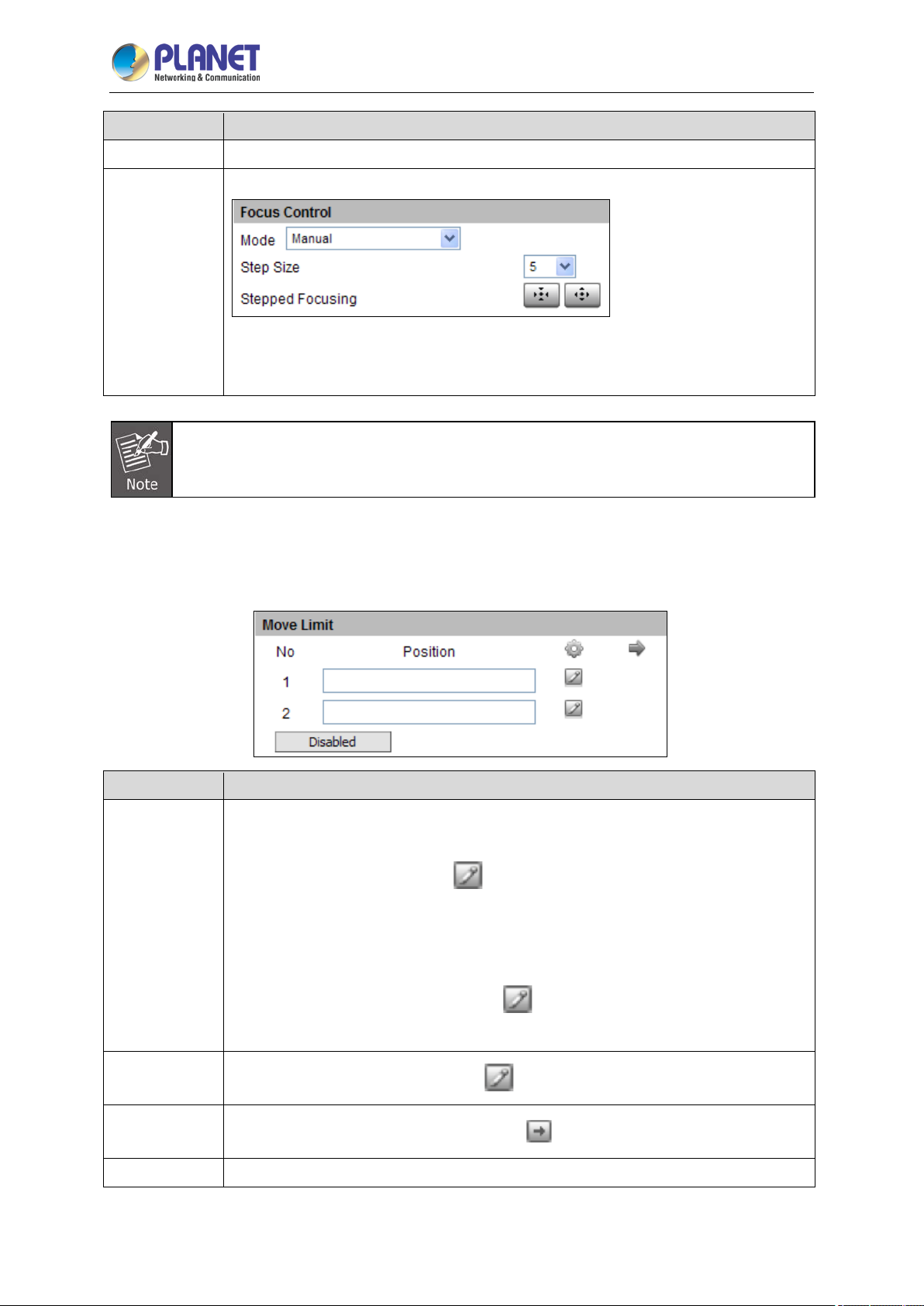
Focus Control:
After zooming the camera in or out, it is recommended to readjust the focus.
Parameters Description
Auto Refocus
Select this option to let the camera automatically adjust the focus after zooming.
Page 46
2 Mega-pixel IR PoE Plus Speed Dome IP Camera
46
Parameters Description
After Zoom:
ICA-E6265
Manual
When an option is selected, click the Refocus button to apply the focus adjustment.
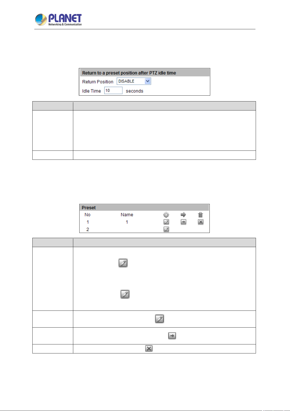
Move Limit:
Users can limit the movement of the camera from one point to another.
Select this option to manually adjust the focus.
This feature is useful if the automatic focus position is not the position that the user
wants to achieve. To adjust the focus manually, select the Step Size and then click
the step focus in or focus out icons until the desired focus is achieved.
Parameters Description
Position
Set
Go to
Disabled
To set the limit, do the following:
1. Click on the Position 1 text box, then pan and tilt the camera to the starting target
area of limitation, then click the
coordinates appear on the Position 1 box.
2. Click on the Position 2 text box, then tilt the camera to the ending target tilt
limitation, then click the corresponding
limit. The position coordinates appear on the Position 2 box.
To set the position as the limit, click
To go to the limitation points directly, click
To disable this limitation, click the Disabled button.
to set that area as the first limit. The position
button to set that area as the other
.
.
Page 47
2 Mega-pixel IR PoE Plus Speed Dome IP Camera
47
ICA-E6265
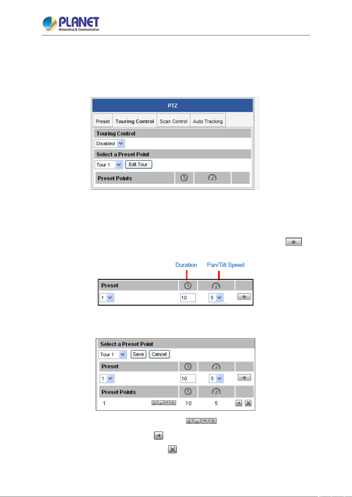
Return to a preset position after PTZ idle time
This feature allows the camera to go directly to a predefined position after an idle period of time.
Idle time refers to the time when the camera has no operation like pan, tilt, zoom or tour activity.
Parameters Description
Return
Position
Idle Time
Preset
Preset points are user-defined areas that the camera can zoom in to. A series of preset points can be
grouped as one tour.
Parameters Description
Preset
To select one of the following options:
a. Home Position: The camera will go to the home position.
b. Preset point name: The camera will go to the preset point which is already
configured.
c. DISABLE: To disable this function.
Input the duration of time (seconds) wherein the camera is considered idle.
To create a preset point, do the following:
Set
Go to
Delete
1. On Preset, click
2. Under the Name field, input a preset point name.
3. Pan, tilt, and zoom on the area that you want to set as the preset point.
4. Once done, click
5. Repeat the above procedures to create more preset points.
To set the position as the limit, click
To go to the limitation points directly, click
To delete the preset point, click
to start creating a preset point.
again to close and complete the preset point.
.
.
.
Page 48
2 Mega-pixel IR PoE Plus Speed Dome IP Camera
48
ICA-E6265
3.4.2 Touring Control
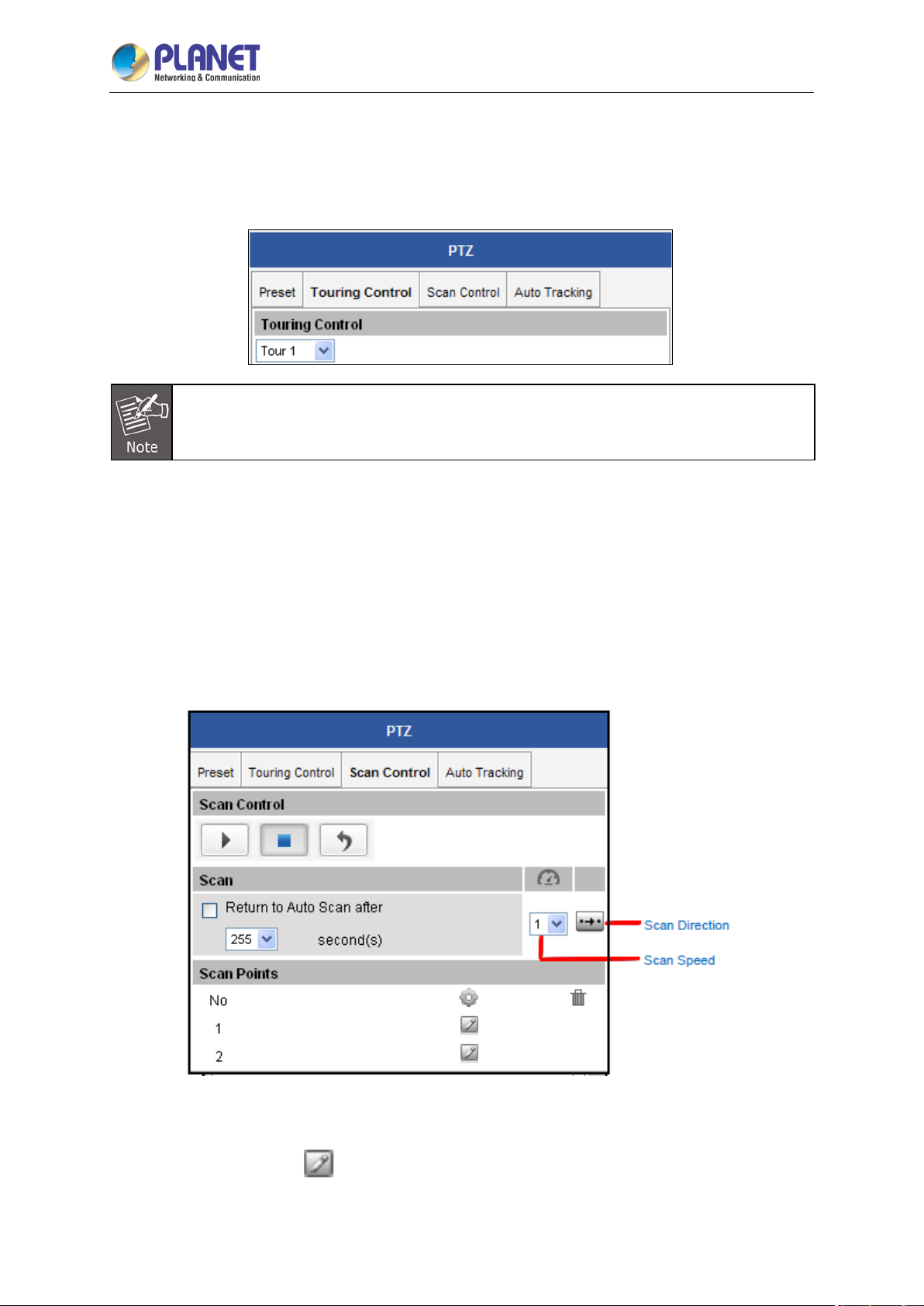
Once a preset point is created, the Touring Control page tab appears. Click the Touring Control page
tab to configure the Preset Tour. A Preset Tour directs the camera to cycle through a sequence of
preset points and stay on each preset point for a specific time.
To set or modify a tour, do the following:
(1) On Select a Preset Point, select a tour and then click Edit Tour.
(2) Select a preset point from the list, set the duration (sec) of how long the camera will stay in that
point and the pan/tilt speed (the bigger the number, the faster the speed), and then click
(3) On the Preset Points, the preset points added to the Tour are listed.
.
To change the sequence of preset points, click the (first/up/down/last) icons.
To directly go to the preset point, click
To delete the preset point from the list, click
.
.
Page 49
2 Mega-pixel IR PoE Plus Speed Dome IP Camera
49
ICA-E6265
(4) Repeat steps 2 and 3 to add more preset points to the tour.
(5) Once done, click the Save button on Select a Preset Point.
(6) On Touring Control, select the tour name to activate. Once activated, the camera will start the
tour.
Ensure Auto Tracking is disabled to use Touring Control.
3.4.3 Scan Control
The Scan Control page enables the camera to go from one predefined point to another by scanning the
view horizontally without losing focus. Unlike in preset tours, wherein the camera goes to one preset
point to another quickly and focusing only on the present point area, scan function goes over point 1 to
point 2 on a steady pace with the whole viewing angle in complete focus. The scan speed can also be
configured according to user preference.
Click the Scan Control page tab to configure scan function.
To set or modify scan points, do the following:
(1) On Scan Points, click
(2) Pan and tilt on the area that you want to set as scan point 1.
of scan point 1 to set the scan starting point.
Page 50
2 Mega-pixel IR PoE Plus Speed Dome IP Camera
50
(3) Once done, click again to close and complete first scan point.
ICA-E6265
(4) Click
(5) Pan and tilt on the area that you want to set as the ending point.
(6) Once done, click
(7) Select the preferred Scan Speed.
(8) Select the preferred Scan Direction: Clockwise or counter-clockwise.
Parameters Description
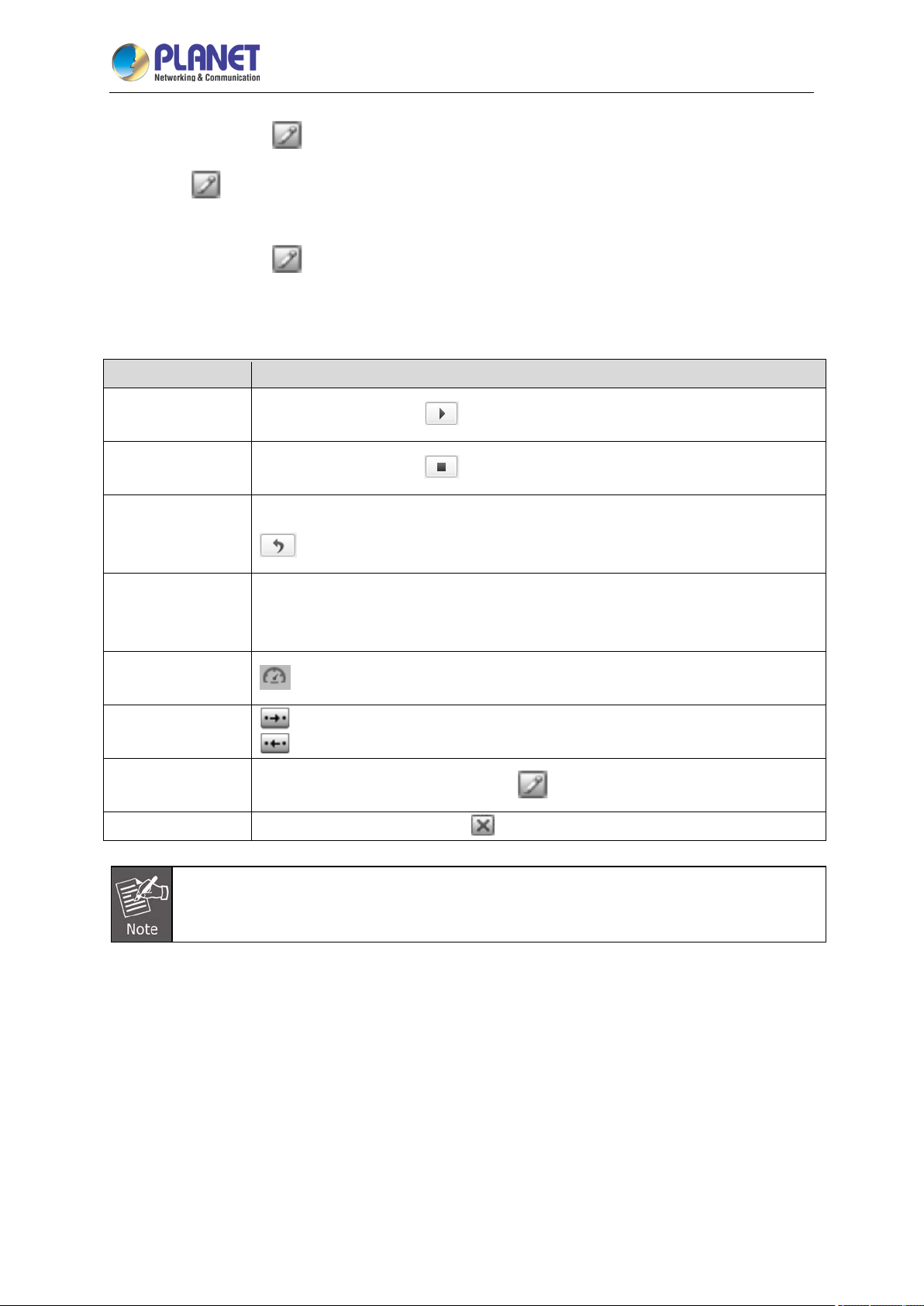
Start Scanning
Stop Scanning
Restart Scanning
Return to Auto
Scan after
of scan point 2 to set the scan ending point.
again to close and complete scan point 2.
To start scanning, click
To stop scanning, click
To restart scanning from the starting point while scanning is in progress, click
.
When scanning is interrupted by other camera operation, like pan, tilt, zoom, etc.,
checking Return to Auto Scan after box enables the camera to resume scan
function after the defined period of time (seconds).
.
.
Scan Speed
: The bigger the number, the faster the speed.
Scan Direction
Set
Delete
If both Tour and Scan Controls are enabled at the same time, Touring Control takes priority
over Scan. Tour must be disabled first to use the Scan function.
: Clockwise
: Anti-clockwise
To set the position as the point, click
To delete the scan point, click
.
.
3.4.4 Auto Tracking
Auto Tracking captures moving objects within the view and follows the objects as they move around
providing unattended surveillance. In case of opposing moving objects, the camera follows the objects
which are more in focus.
Note that Auto Tracking cannot function at the same time with Touring Control and Scan Control. To
enable Auto Tracking, disable Touring Control or Scan Control first.
Page 51
2 Mega-pixel IR PoE Plus Speed Dome IP Camera
51
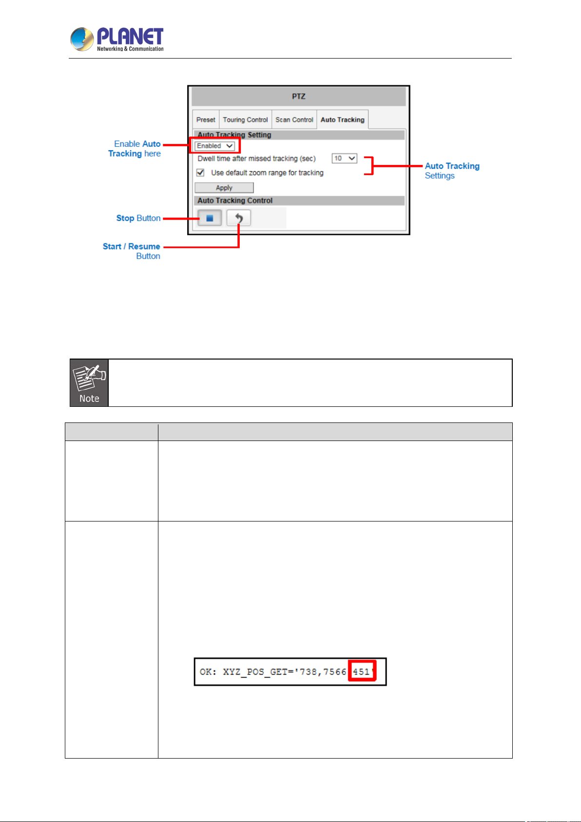
To configure the Auto Tracking function, do the following:
(1) Select Enabled on the box.
(2) Click Apply to confirm enable Auto Tracking.
ICA-E6265
If this box is Enabled, Touring Control and Scan Control functions are automatically
disabled.
Parameters Description
Dwell time after
missed tracking
(sec)
Use default zoom
range for tracking
It is the amount of time (in seconds) when the camera will stay in the last
position where the moving objects are detected.
After the objects being tracked are already out of viewing range and no other
movements are detected within the specified time, the camera goes back to the
viewing position where the Apply button was last clicked.
The default zoom range is enabled by default.
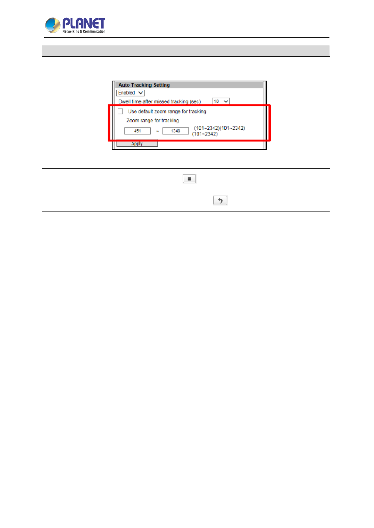
To limit the zoom range, follow the procedures below:
1. Use the URL command to get the maximum zoom out and zoom in position of
the camera.
a. Zoom out the camera to desired minimum position.
b. On the address bar, type the URL command
http://[ip_address:port]/cgi-bin/cmd/encoder?XYZ_POS_GET
c. A confirmation text with the XYZ position, as below, appears.
The last value (Z) is the zoom position. Take note of this value.
d. To get the maximum zoom position, zoom in the camera to the desired
position and repeat steps b and c.
2. Uncheck Use default zoom range for tracking.
Page 52
2 Mega-pixel IR PoE Plus Speed Dome IP Camera
52
Parameters Description
3. On Zoom range for tracking, type the zoom position values that you have
taken note of. For example, 451 and 1348.
4. Click Apply to save and apply settings.
Stop Scanning
To stop auto tracking, click
Restart Scanning
To start or resume auto tracking, click
.
ICA-E6265
.
Page 53
2 Mega-pixel IR PoE Plus Speed Dome IP Camera
53
ICA-E6265
3.5 Configuration
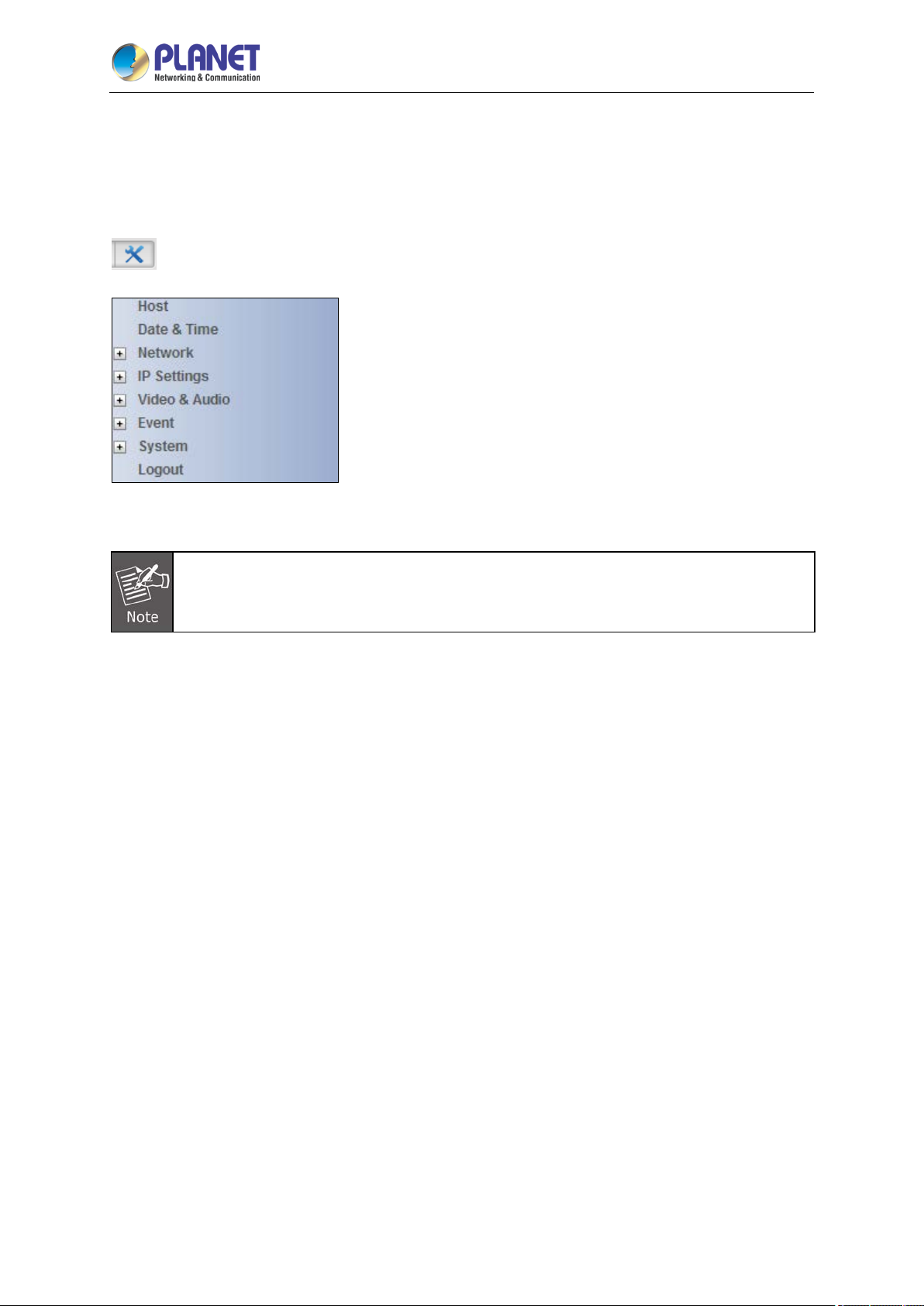
To configure any of the camera settings, go to the Setup menu by pressing the following button on the
Live View page:
- Go to
The left side of the Setup page contains the list of Setup items.
The exact content of the menu list varies for each camera, depending on the actual
capabilities of each camera. This manual, however, is designed to explai n all the possib le
functions.
Several items on the Setup page are divided into groups, such as Network, IP Settings, etc. You can
expand the groups to see the sub-items by pressing the [+] button.
The following chapters of this manual explain each Setup item separately. The chapters are listed in
the same order as the list of Setup menu items.
Page 54
2 Mega-pixel IR PoE Plus Speed Dome IP Camera
54
ICA-E6265
3.6 Host Setup
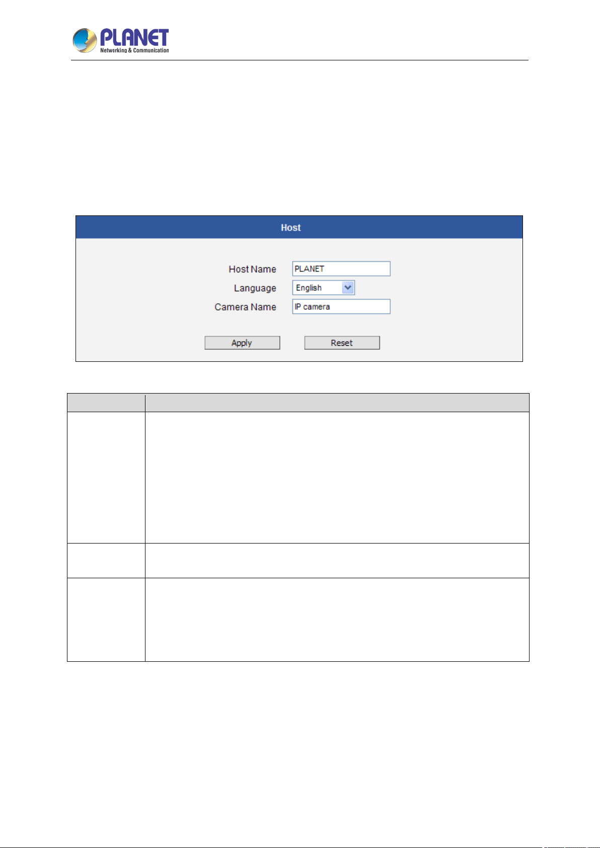
The “Host Setup” section allows the administrator to define the name of the camera and preferred user
interface language.
3.6.1 Host
Parameters Description
Host Name
Language
Camera Name
Host Name is used to identify the camera by a DHCP server. In some networks with
very strict security policy, it is required that all the network devices should have their
host name, and when the devices attempt to access the network by requesting an IP
address from a DHCP server, the DHCP server would check if the host name is
among the allowed devices. On this page, it is possible to edit the Host Name. To
actually include the Host Name in DHCP discovery packet sent from a camera,
please go to IP Settings and make sure the device is in Dynamic IP Address mode
and “Use host name” is checked.
Language selection under Host has the same purpose as the one on the login page
of Web Configuration.
Camera Name is used to identify the device by Video Management System or by
Software Tools. Usually, upon installation of the camera, the actual installation
location is used as an easy-to-remember Camera Name, such as “Front Gate” or
“Elevator 1”. In many cases the VMS is able to modify the Camera Name directly via
its own user interface without needing to access Web Configuration.
After changing any of the items above, press Apply to save the changes. The Reset button undoes
the changes that had just been made but not Applied yet.
Page 55
2 Mega-pixel IR PoE Plus Speed Dome IP Camera
55
ICA-E6265
3.6.2 GPS Position
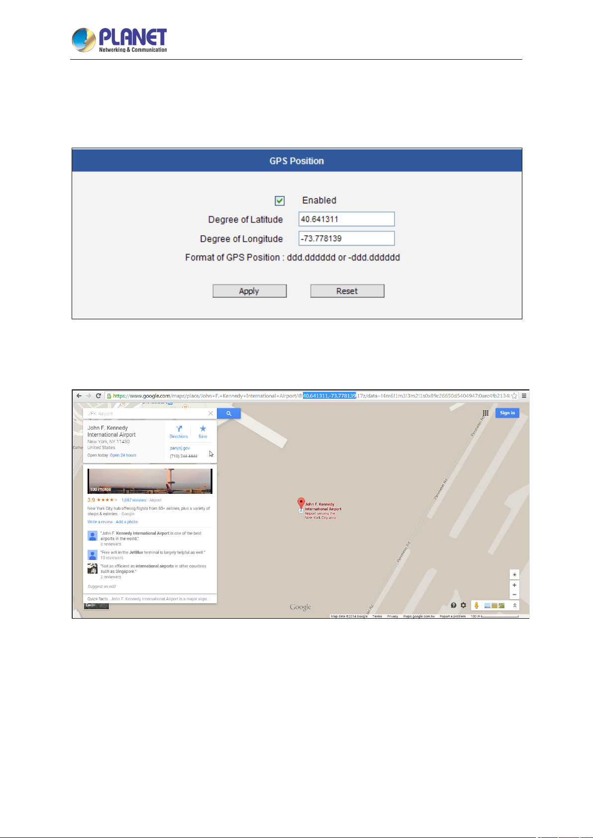
This section allows users to manually set the GPS position of the camera and find the location of the
camera on the map when using a Network Video Recorder (NVR).
Check the Enabled box to enable this feature.
Find the camera location on Google maps, for example, installed in the airport.
Copy the first GPS coordinates from the URL bar and paste it on Degree of Latitude. Copy the
second part of the GPS coordinates to Degree of Longitude.
Press Apply to save the changes.
Page 56
2 Mega-pixel IR PoE Plus Speed Dome IP Camera
56
ICA-E6265
3.7 Date and Time
Each video frame contains a time stamp. The accuracy of the time stamp is very important for incident
investigators. Therefore the clock of the camera has to be adjusted to the most accurate time possible.
The section Date & Time provides the options for adjusting the date and time of the camera.
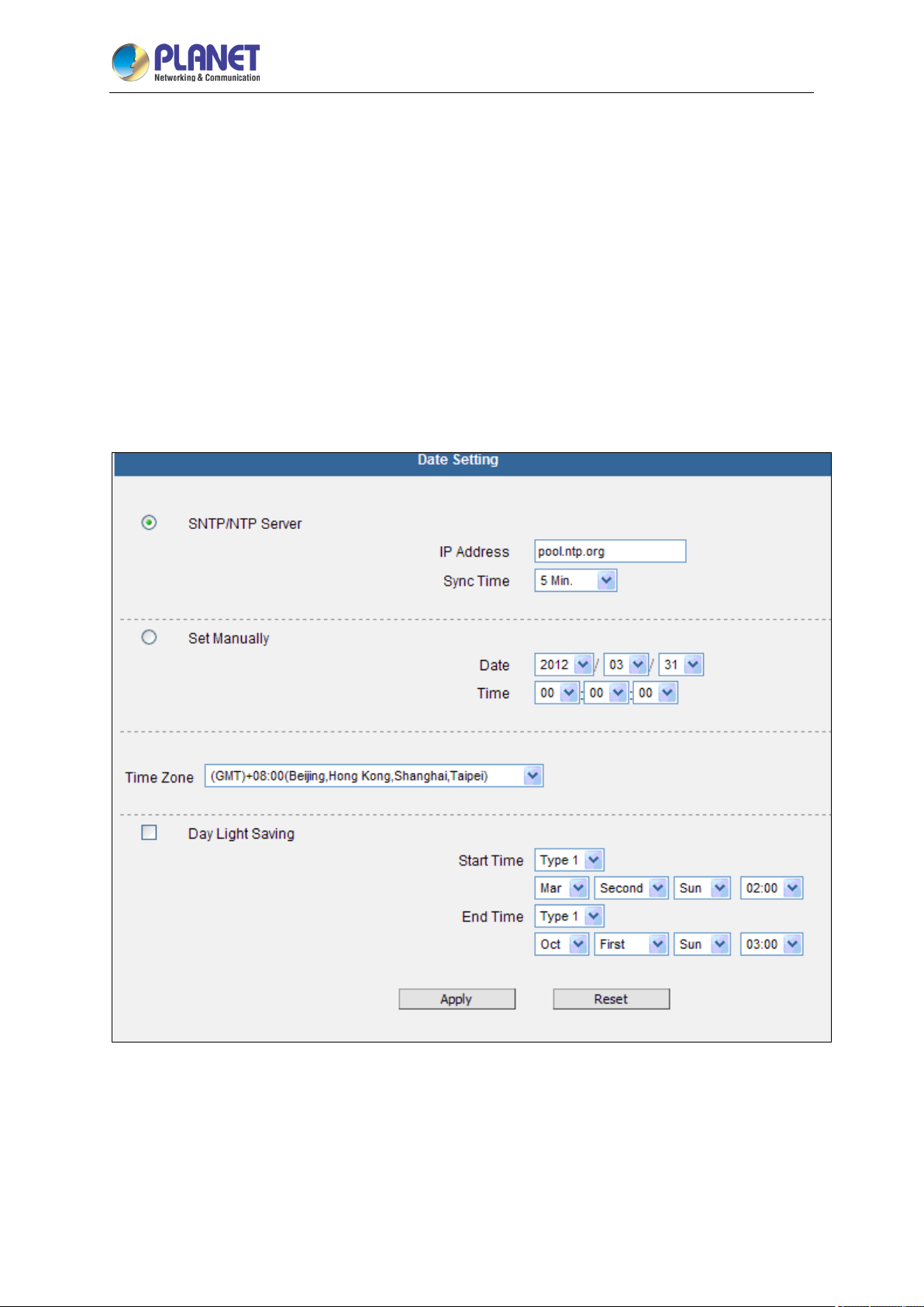
There are two ways to adjust the date and time – automatically by getting date and time regularly
from any of the NTP servers worldwide, or manually by selecting proper time zone, date and time.
The automatic way can be used only if the camera has an access to NTP servers. If you are using an
isolated Local Area Network without Internet access, you can only use Manual date and time
adjustment mode.
When choosing SNTP/NTP Server for automatic date and time updating, you can key-in the IP
address of the NTP server and the time interval for automatic time synchronization. If you want to
key-in the domain name of NTP server instead, please make sure the DNS server IP address has
been set under IP Settings; otherwise, the camera will not be able to resolve the domain name of the
NTP server.
Page 57

2 Mega-pixel IR PoE Plus Speed Dome IP Camera
57
ICA-E6265
If all the cameras are getting the date and time from the same NTP Server, you can be most sure that
the video clips from different cameras can be well synchronized later for comparison purposes.
To choose the most suitable NTP Server to synchronize date and time with, please refer to the
worldwide pool of NTP Servers:
When choosing Set Manually mode, you can adjust the date and time by the select boxes. Choose
the appropriate Time Zone from the select box, too. If your location is not listed there, then pick any of
the listed zones which GMT is identical with your location.
For the countries with daylight saving policy, there is Day Light Saving function with two different
types:
Type 1 – define the starting or ending time of daylight saving period by the number of the week in the
month (First, Second, Third or Last week).
Type 2 – define the starting or ending time of daylight saving period by the exact date in the month
(1-31).
Whether to choose Type 1 or Type 2, please refer to the daylight saving policy of the given country.
After changing any of the items above, press Apply to save the changes. The Reset button undoes the
changes that had just been made but not Applied yet.
http://www.pool.ntp.org/en/
Page 58
2 Mega-pixel IR PoE Plus Speed Dome IP Camera
58
ICA-E6265
3.8 Network
The section Network provides the list of network related functions and services. The [+] mark before
Network indicates that the list can be expanded by clicking on it. Once expanded, the list can later be
collapsed again by clicking on the [-] mark.
3.8.1 IP Address Filtering
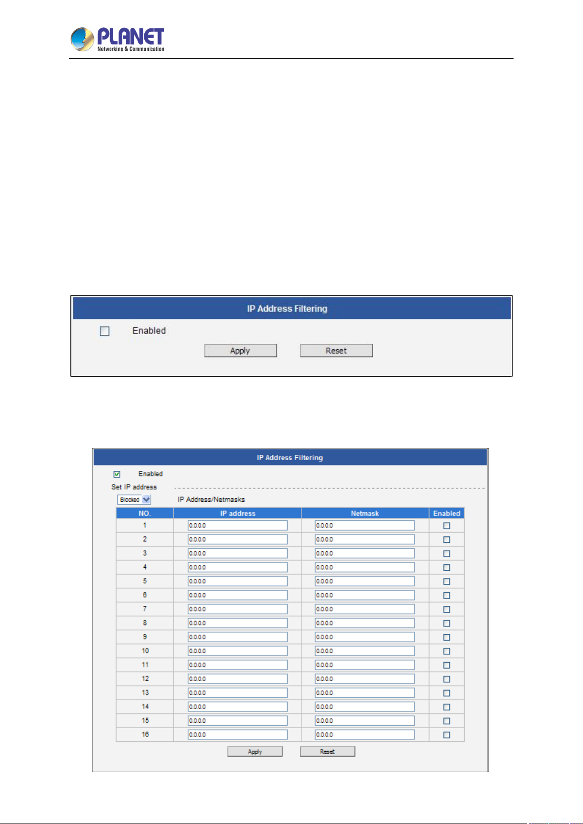
By “IP Address Filtering” function it is possible to define which devices (their IP addresses) are
allowed to connect to this camera, and which devices are forbidden to connect to this camera.
Check the box “Enabled” to activate the IP address filtering function and press Apply.
Below you can select either “Allowed” or “Blocked” list to add items there and Enable them with the
checkbox behind each row.
Page 59
2 Mega-pixel IR PoE Plus Speed Dome IP Camera
59
ICA-E6265
“Allowed” mode will refuse access to all IP addresses except the ones listed below.
“Blocked” mode will accept all incoming access except the IP addresses listed below.
Using Netmask (Subnet Mask) allows you to set filtering for a w hole range of IP address at once,
without the need to enter all of them individually. If you are not sure about the function of Netmask,
then you should use 255.255.255.255, and it will affect only a single IP address per line of entry, or use
255.255.255.0 to use the same setting for all IP addresses starting with the same three numbers. .
After changing any of the items above, press Apply to save the changes. The Reset button undoes
the changes that had just been made but not Applied yet.
Do not accidentally block your own IP address that you are connecting from; otherwise,
you will not be able to access the camera any more to undo the changes. If this happens
by mistake, you can do the hardware reset – it will clear all the filtering rules.
Page 60
2 Mega-pixel IR PoE Plus Speed Dome IP Camera
60
ICA-E6265
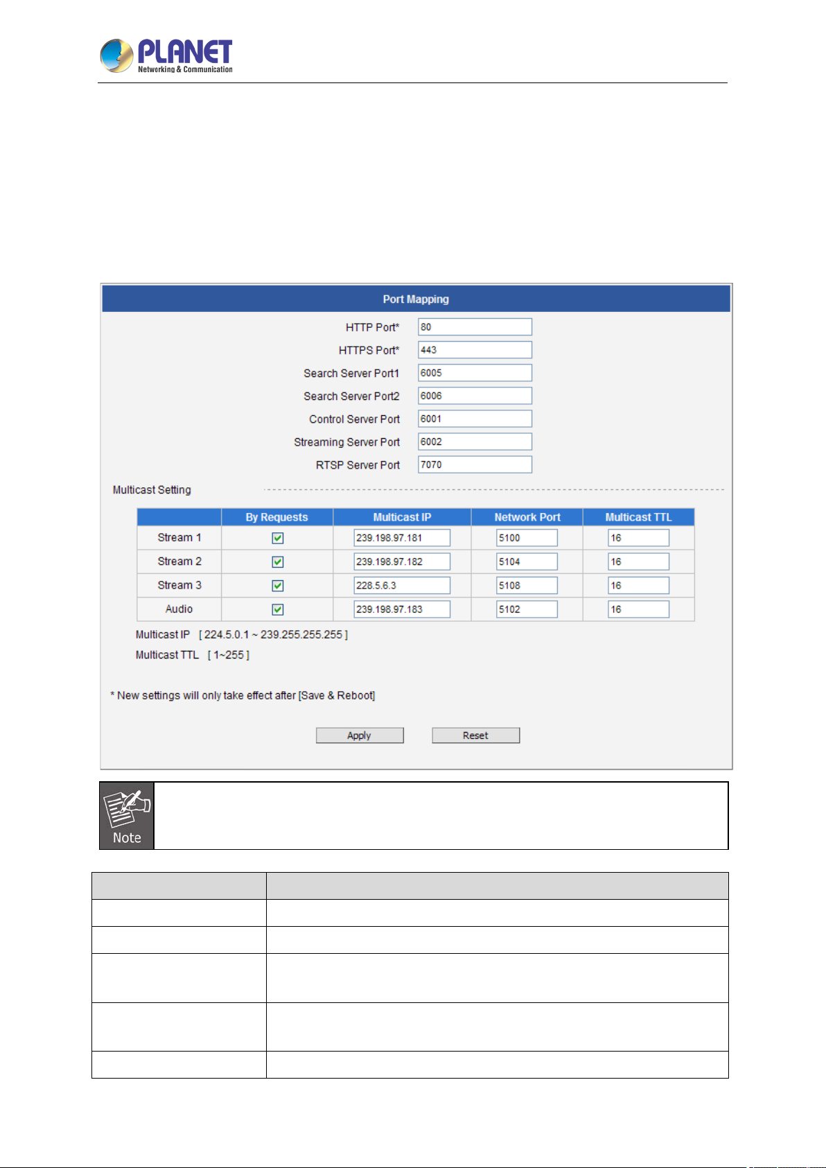
3.8.2 Port Mapping
The section Port Mapping provides the list of services and protocols that require their own port
number for communication. By default, the camera already has all the ports defined. On this page, the
user can modify the port numbers in case there is a specific need for that. Most often, the HTTP port is
changed to something other than 80 in order to match with easy-to-remember port forwarding rules of
the router that acts as a bridge between local area network and Internet.
Some items appear only if the camera model supports the function.
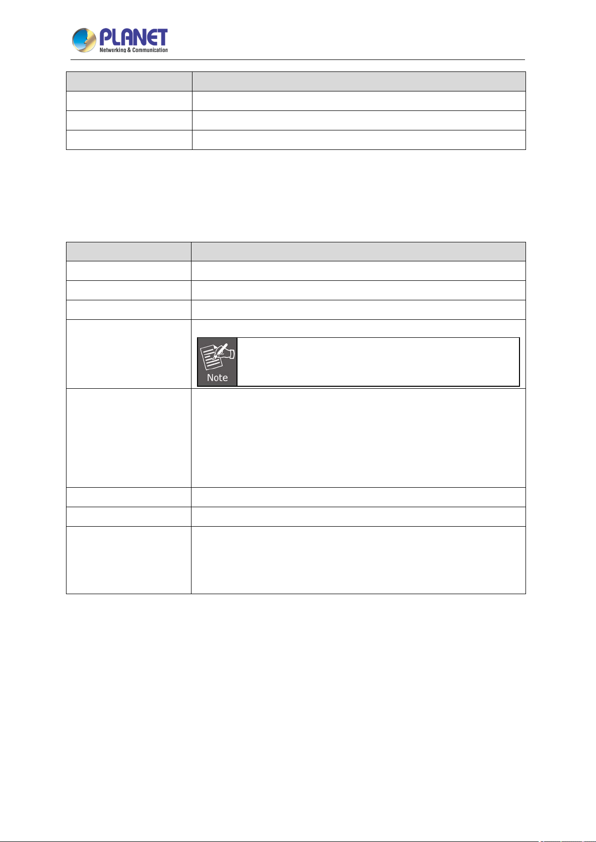
Parameters Description
HTTP port
HTTPS Port
Search Server Port1
Search Server Port2
Control Server Port
Select the port assigned for HTTP protocol access.
Select the port assigned for HTTPS protocol access.
Select the first port used by server search applications to detect this IP
device.
Select the second port used by server search applications to detect this
IP device.
Select the port used to support video control function by application
Page 61
2 Mega-pixel IR PoE Plus Speed Dome IP Camera
61
ICA-E6265
Parameters Description
programs (e.g., NVR).
Streaming Server Port
RTSP Server Port
Select the port used by this IP device for Video Streaming (TCP).
Select the port assigned for RTSP protocol access.
Multicast Setting allows users to configure the IP addresses and ports for multicast video and audio
(supported models only) streams. Multicast is a protocol where a data stream is sent only once and
shared to requesting devices. This in turn saves network bandwidth. However, to use this feature,
network devices, such as routers and switches, should support IP multicast.
Parameters Description
Stream 1
Stream 2
Stream 3
Refers to the video stream 1.
Refers to the video stream 2.
Refers to the video stream 3.
Refers to the audio stream.
Audio
Appears only if the camera model supports audio
input/output.
When checked, the video or audio stream will be streamed only to a
particular receiver when that receiver sends a request or in the case of
the Network Video Recorder (NVR), select to view or record the stream. If
By Request
unchecked, the video or audio stream will constantly be streamed to the
network whether there are devices viewing the video or not. To save on
network bandwidth, it is recommended to check this function.
Multicast IP
Network Port
Set the multicast IP of the corresponding stream.
Enter the assigned port for the corresponding stream.
Enter the multicast TTL (time-to-live) of the corresponding stream. This
value determines the time span (in seconds) when the packet is retained
Multicast TTL
in the network. When the time expires and no request is received, the
packet is then discarded.
After changing any of the items above, press Apply to save the changes. The Reset button undoes
the changes that had just been made but not Applied yet. New port settings will only take effect after
pressing System -> Save & Reboot.
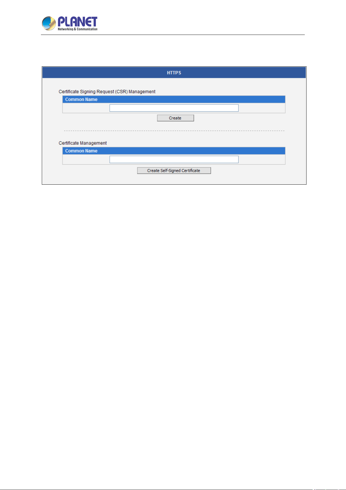
3.8.3 HTTPS
HTTPS protocol allows creating a secure channel over an insecure network in order to protect the data
sent between the camera and its counterpart. Two things are required to have a s ecure
communication – encrypted data, and verified counterpart of the communication. To make sure that
the messages are being sent and received from true counterpart, the certificate is needed.
Page 62
2 Mega-pixel IR PoE Plus Speed Dome IP Camera
62
ICA-E6265
There are two methods to create certificates – Certificate Signing Request (CSR) and Self-Signed
Certificate.
Certificate Signing Request (CSR): User uses a s igned certificate issued by trusted Certification
Authority (CA).
Self-Signed Certificate: User wants to use the certificate created and issued by user himself.
Press Create or Create Self-Signed Certificate button and configure settings in the pop-up screen to
install the certificate.
Note that the new setting will only take effect after Save & Reboot.
3.8.4 IEEE 802.1X
IEEE 802.1X is an IEEE standard for port-based Network Access Control. 802.1X authentication
involves three parties: a supplicant, an authenticator, and an authentication server.
The supplicant is a client device (such as an IP camera) that wishes to attach to the LAN/WLAN. The
authenticator is a net work device, such as an E thernet switch or wireless access point; and the
authentication server is typically a host running software supporting the RADIUS and EAP protocols.
The authenticator acts like a security guard to a protected network. The supplicant (i.e., client device)
is not allowed access through the authenticator to the protected side of the network until the
supplicant’s identity has been validated and authorized. An analogy to this is providing a valid passport
at an airport before being allowed to pass through security to the terminal. With 802.1X port-based
authentication, the supplicant provides credentials, such as user name/password or digital certificate,
to the authenticator, and the authenticator forwards the credentials to the authentication server for
verification. If the authentication server determines the credentials are valid, the supplicant (client
device) is allowed to access resources located on the protected side of the network.
Page 63
2 Mega-pixel IR PoE Plus Speed Dome IP Camera
63
ICA-E6265
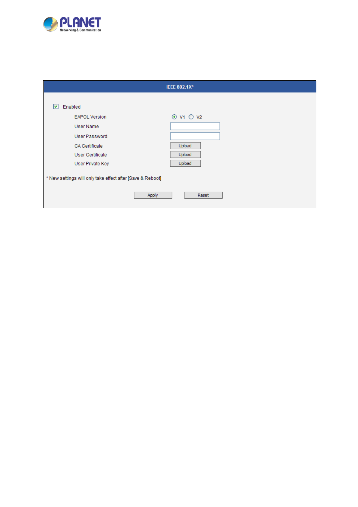
Please enable IEEE 802.1X and configure settings on the screen below. Note that the new setting will
only take effect after “Save & Reboot”.
EAPOL Version 1 and 2 are the 802.1X communication types. User name and User password area
created by user and set in RADIUS server. Certificates and Private Key are provided by RADIUS
Server.
If certificates or private key exist already, there will be a Remove button behind these items, in order to
remove these items when necessary.
After changing any of the items above, press Apply to save the changes. The Reset button undoes
the changes that had just been made but not Applied yet.
3.8.5 SNMP Setting
The SNMP Setting item displays the SNMP configuration page.
SNMP provides an easy way to manage network devices. The main features are:
(1) Monitoring device uptime
(2) System detail description. (e.g., model name, model description and firmware version.)
(3) Collect interface information. (e.g., MAC address, interface speed and local port.)
(4) Measuring network interface throughput.
Page 64
2 Mega-pixel IR PoE Plus Speed Dome IP Camera
64
ICA-E6265
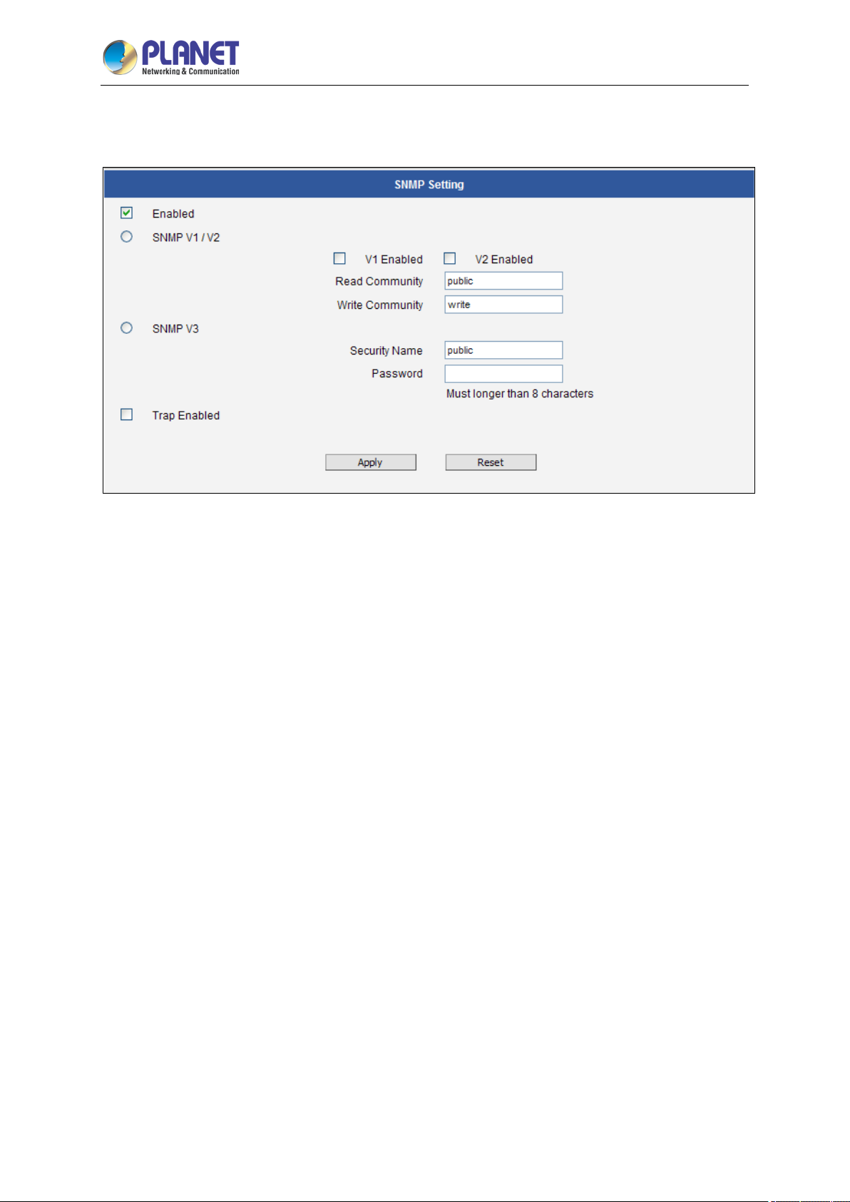
To use SNMP, just enable SNMP function in the camera (SNMP agents) and run SNMP management
software in server (NMS: Network Management Station) to connect to the devices.
The SNMP agent supports versions 1, 2 and 3. SNMP v1 is the initial implementation of SNMP. SNMP
v2 is proposed to enhance the performance of management, such as the communication of server and
devices, the confirmation of information delivery and receipt. Primary additions in SNMP v3 concern
security and remote configuration enhancements.
SNMP v1/v2 uses “Community” name as password to authenticate identity. “Read Community” is the
password for server to get information from devices. “Write Community” is the password for server to
edit values on devices. The default is “public” for Read Community and “write” for Write Community. Of
course, you can set any other password as your read/write community.
You can enable v1, v2 or both. Click “Apply” after you’ve completed the setup.
The security method of SNMP v3 uses account/password for authentication. “Security Name” is the
account name to be us ed with your “Password”. The default security name is “public” and the
password must be at least 8 characters long. You also can set any other security name or password.
Click “Apply” after you’ve completed the setup.
SNMP function is now enabled. You may now install and run the SNMP management software on
computer server.
Page 65
2 Mega-pixel IR PoE Plus Speed Dome IP Camera
65
ICA-E6265
SNMP Trap Usage:
SNMP traps enable notifications from devices. Devices may send message to the management server
whenever significant events occur such as cold start, warm start and authentication failure. The
manager will get the information immediately and take action if necessary.
Cold start means device reboot by power disconnection. Warm start means device reboot by
firmware without power disconnection. If there are other parties that attempt to connect to the device
with a wrong security password under SNMP v1, v2 or v3 setting, the device will send an
authentication failure message to the management server.
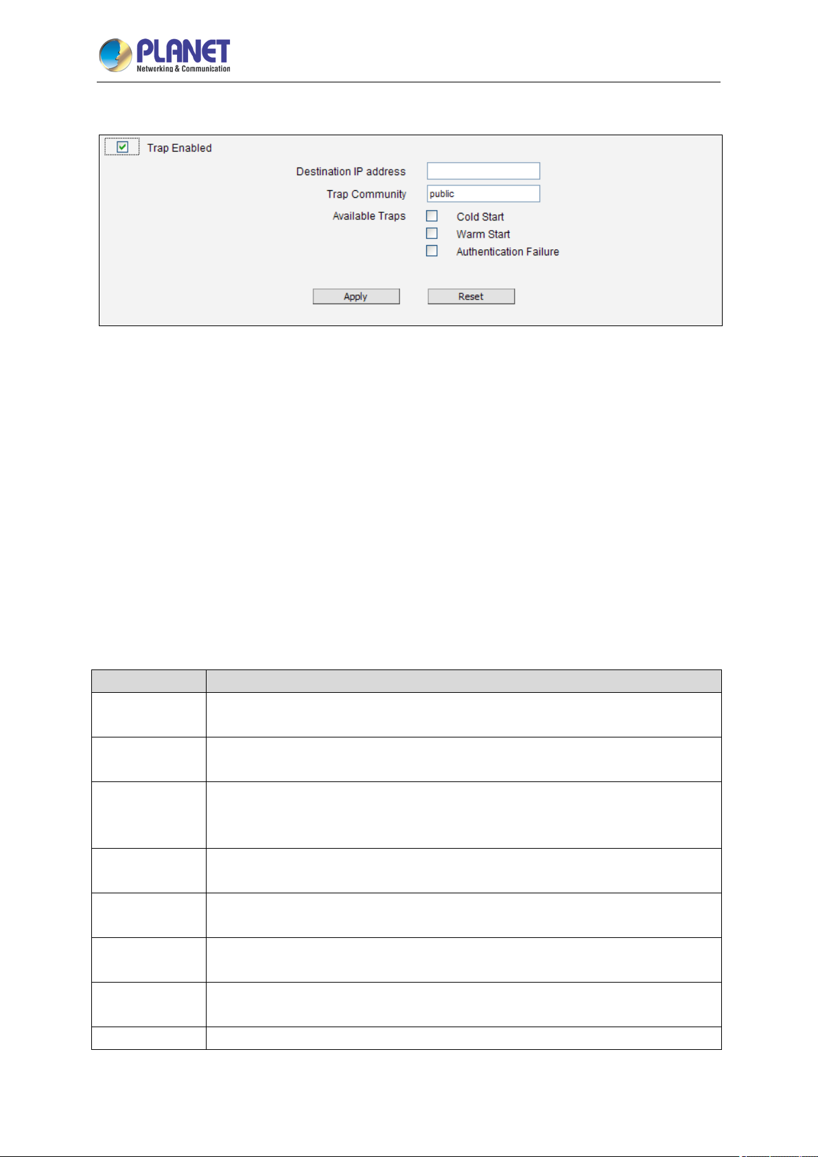
To enable SNMP Trap function in the camera, type the IP address of the computer running the SNMP
management software and type trap community as password to allow server to get trap message from
device (Default is public). Select available traps and click “Apply”.
Camera’s SNMP offers the following information:
Group Description
System
Interface
Address
Translation
IP
ICMP
TCP
UDP
SNMP Provides the related statistics through SNMP
Provides general information about the managed device.
For example, system description and system name.
Provides general information from the physical interfaces.
For example, interface speed and MAC addres s.
Provides information about the mapping between network addresses and physical
addresses for each physical interface.
For example, the IP/MAC addresses are to connect to the managed device.
Provides the status and operation of Network Layer (Layer 3).
For example, the informa tio n and traffic flow of received/delivered package.
Provides the status and statistics of ICMP.
For example, amount of receive/error message of ICMP.
Provides the status and operation of Transport Layer (Layer 4) using TCP protocol.
For example, TCP Local Port and incoming/outgoing TCP segments.
Provides the status and operation of Transport Layer (Layer 4) using UDP protocol.
For example, UDP Local Port and in/out datagram.
Page 66
2 Mega-pixel IR PoE Plus Speed Dome IP Camera
66
ICA-E6265
3.8.6 RTP
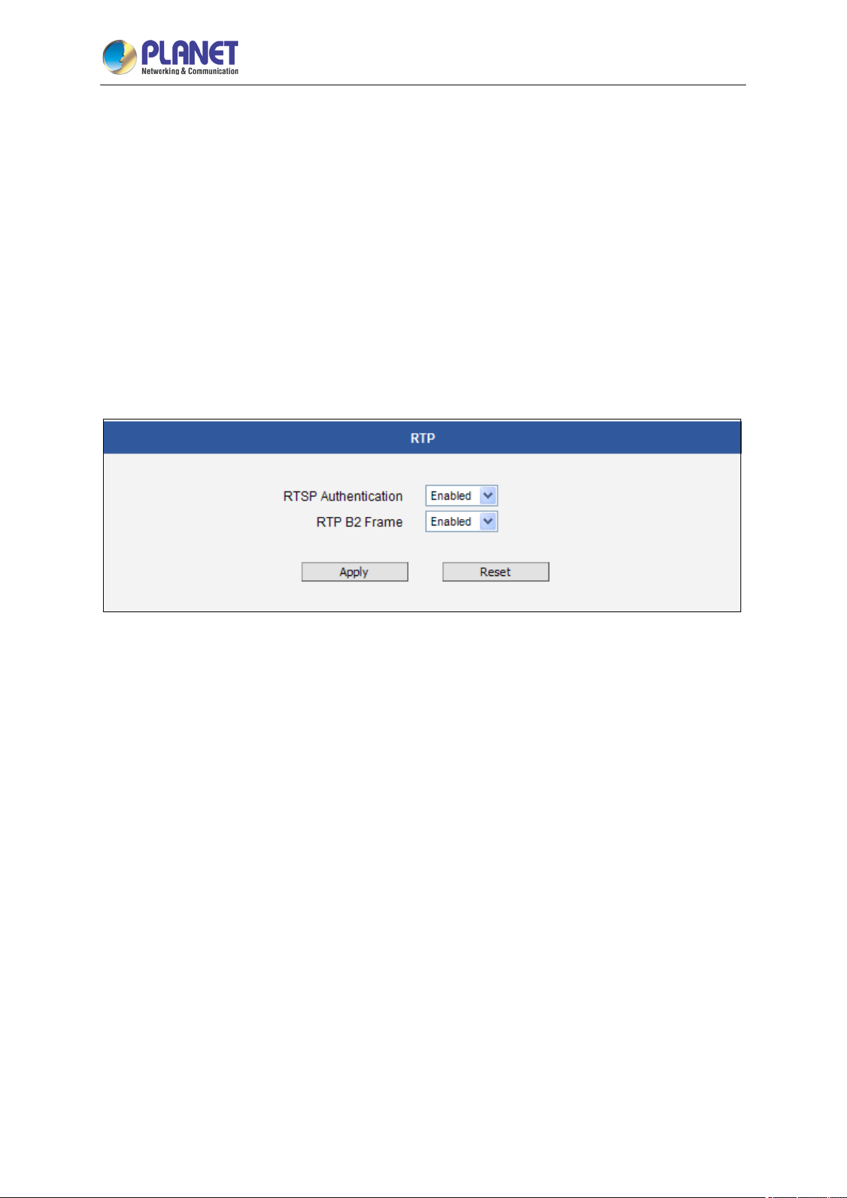
The RTP section allows user to configure RTP Settings.
If the RTSP Authentication is “Enabled”, then the RTP streaming will require account name and
password authentication.
If the RTP B2 Frame is “Enabled”, then the B2 frame is added to every video frame, containing an
additional information, such as motion detection status on each frame, digital input and digital
output levels, passive infrared status, other video intelligence data, frame counter, frame-rate
mode and the frame-rate, bitrate, resolution, timestamp and much more. The user side can
operate with video data easily, including event management, storage consumption estimation, image
resizing for preview, etc.
After changing any of the items above, press Apply to save the changes. The Reset button undoes
the changes that had just been made but not Applied yet.
3.8.7 Network
The Network section contains the controls for the following functions:
Type of Service
UPnP
Bonjour
ONVIF
Page 67
2 Mega-pixel IR PoE Plus Speed Dome IP Camera
67
ICA-E6265
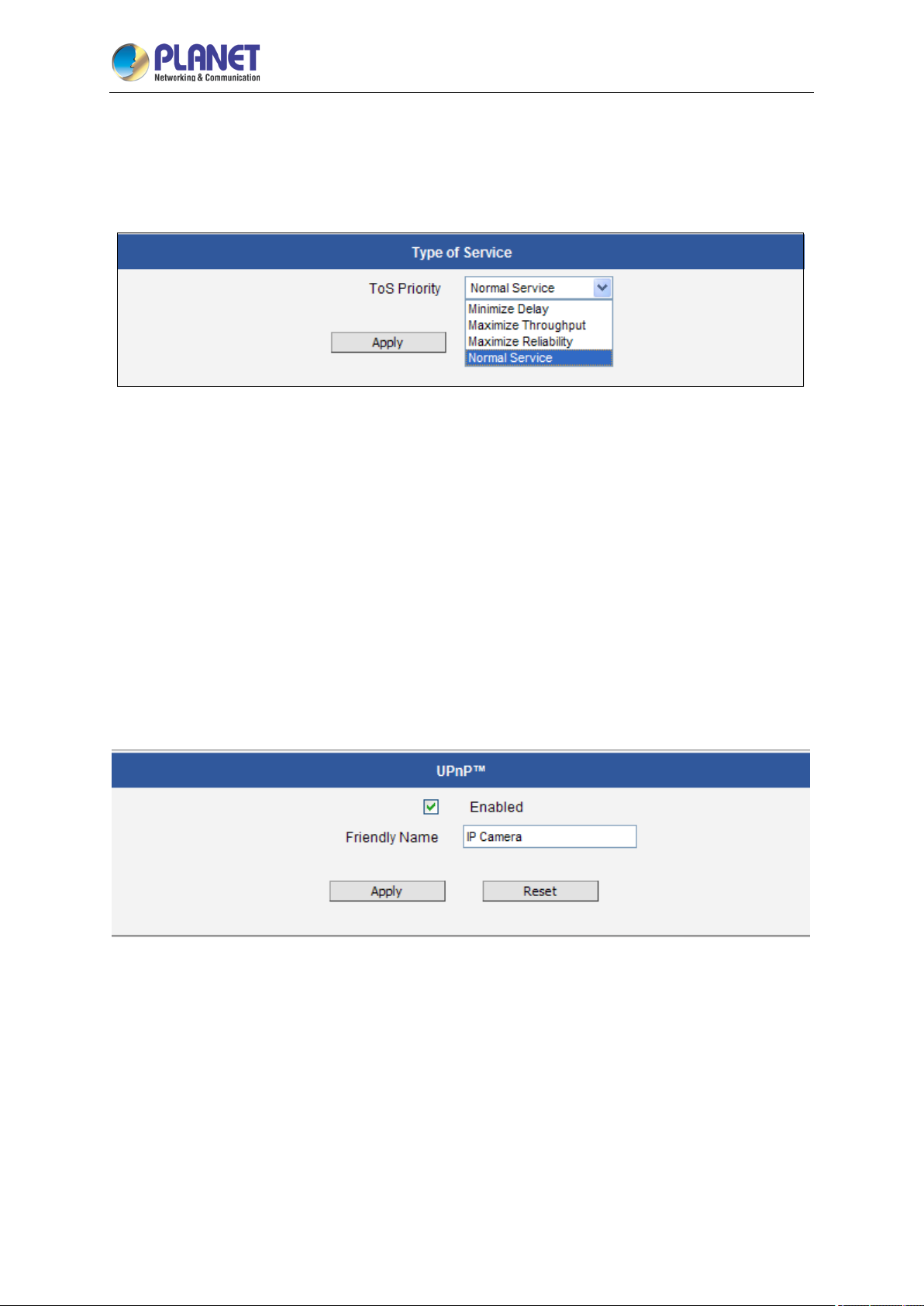
Type of Service
The “Type of Service” provides 4 options to define the priorities of how the data from the camera
should be handled by the routers that support ToS concept. By default, the ToS priority is set as
“Normal Service”.
For special priority arrangement, there are 3 more options:
Minimize Delay
Maximize Throughput
Maximize Reliability
After changing any of the items above, press Apply to save the changes. The Reset button undoes
the changes that had just been made but not Applied yet.
TM
UPnP
The UPnP
the camera. Having the UPnP
TM
section provides the option to enable or disable the Universal Plug and Play capability of
TM
enabled allows the other network devices to seamlessly discover it on
the network for convenient identification and access.
The Friendly Name is a human-readable name for the device that will be displayed when the camera
is found. By default, the serial number of the camera is used as a friendly name; however, the user can
modify the name according to the project needs.
After changing any of the items above, press Apply to save the changes. The Reset button undoes
the changes that had just been made but not Applied yet.
Page 68
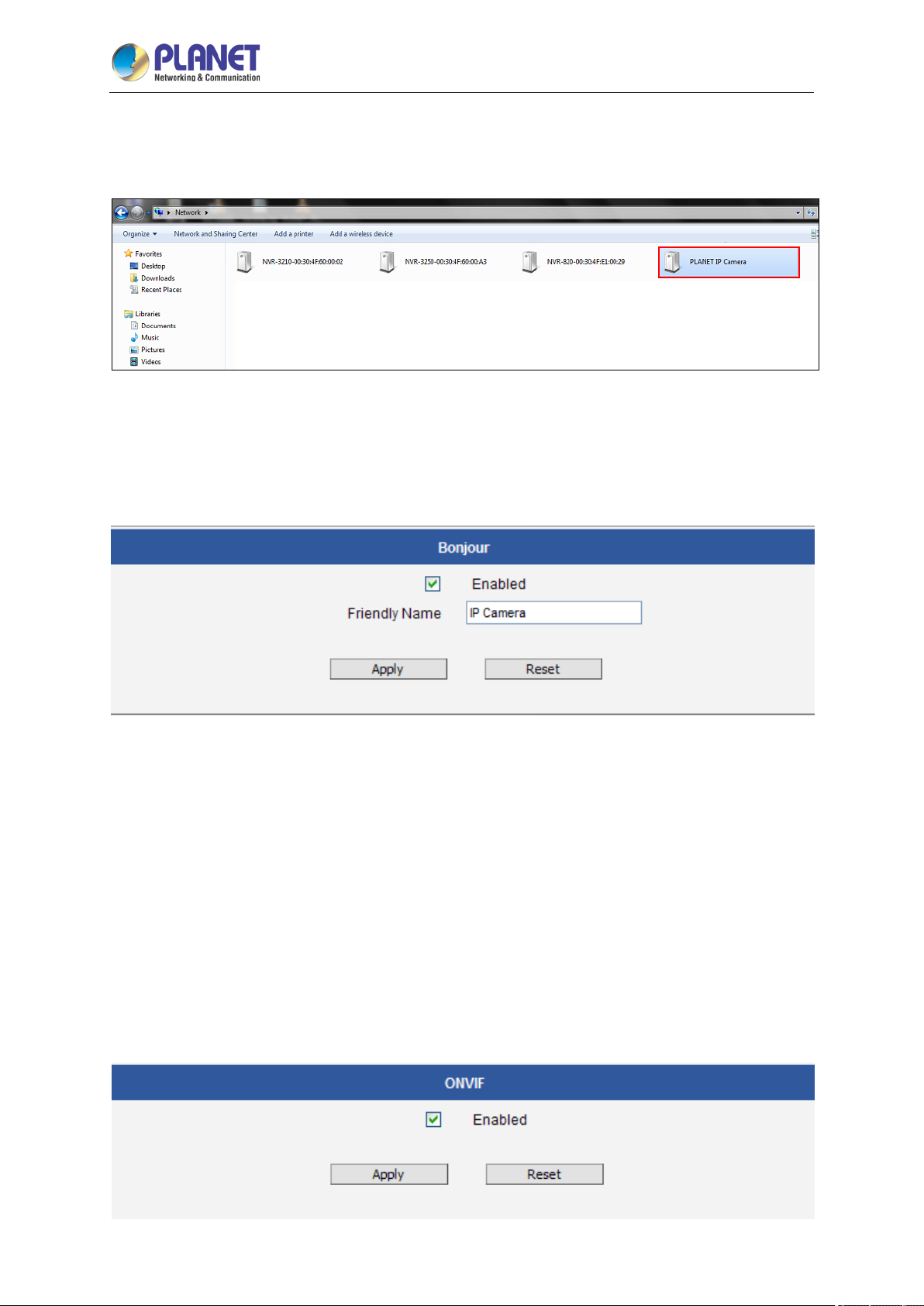
2 Mega-pixel IR PoE Plus Speed Dome IP Camera
68
ICA-E6265
Most of the Windows-based computers have the capability to discover the devices that support
TM
UPnP
will discover the cameras instantly.
Bonjour
The Bonjour section provides the option to enable or disable the ability of the camera to be
discovered by the other network devices using Bonjour protocol, developed by Apple Inc. Both Bonjour
and UPnP serve the similar purpose – to discover devices conveniently.
. Below is the example of Windows 7: By clicking on the Network icon of Windows 7, the PC
Similarly to UPnP, the human readable Friendly Name can be defined by the user. That name will be
displayed when the camera is found in the network. By default, the Friendly Name is the serial number
of the camera; however, the user can modify the name according to the project needs.
After changing any of the items above, press Apply to save the changes. The Reset button undoes
the changes that had just been made but not Applied yet.
ONVIF
The camera with the given firmware is ONVIF 2.2 compliant. By default, the ONVIF function is
enabled.
To disable the ONVIF support, remove the check mark from the check box and press Apply.
Page 69
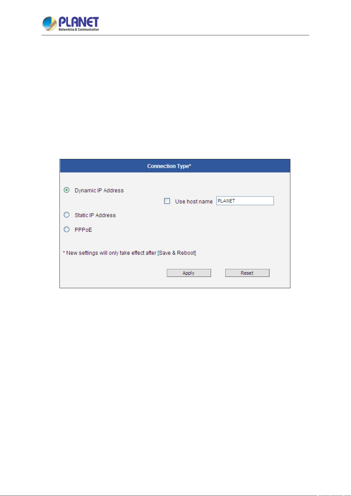
2 Mega-pixel IR PoE Plus Speed Dome IP Camera
69
ICA-E6265
3.9 IP Settings
The IP Settings section provides the options to define how the camera would obtain its IP address,
and to which DNS server should the camera connect, in order to resolve domain names.
3.9.1 Connection Type
The Connection Type allows defining the method of obtaining the IP address of the camera. By
default, the camera is in Dynamic IP Address mode and attempts to get the IP address from a DHCP
server. If such attempt fails after several seconds (for example, the DHCP server does not exist), the
camera will automatically assign itself an IP address, listed under the Static IP Address.
Page 70
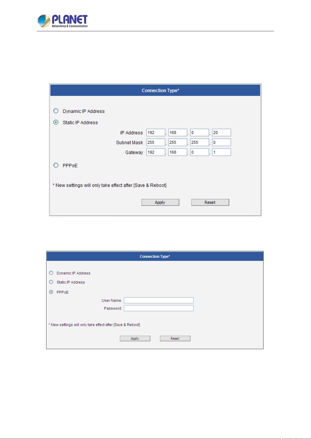
2 Mega-pixel IR PoE Plus Speed Dome IP Camera
70
ICA-E6265
Host Name is used to identify the camera by a DHCP server. In some networks with very strict security
policy, it is required that all the network devices should have their host name, and when the devices
attempt to access the network by requesting an IP address from a DHCP server, the DHCP server
would check if the host name is among the allowed devices. On this page, it is possible to edit the Host
Name and enable or disable the use of host name.
Most installation projects include clear network topology and static IP addresses for each camera. In
such cases, you can change the camera to Static IP Address mode and modify the IP Address,
Subnet Mask and Gateway accordingly.
In some rare cases, the camera may be connected to the control center over Internet. Usually, the
most cost efficient way is to use ADSL connection with PPPoE. To avoid the unexpected changes of IP
addresses by Internet Service Provider upon the restart of the camera, it is recommended to activate a
DDNS service for such scenario, and let the control center connect to the camera by the domain name
instead. Please refer to the DDNS section for more details.
Page 71
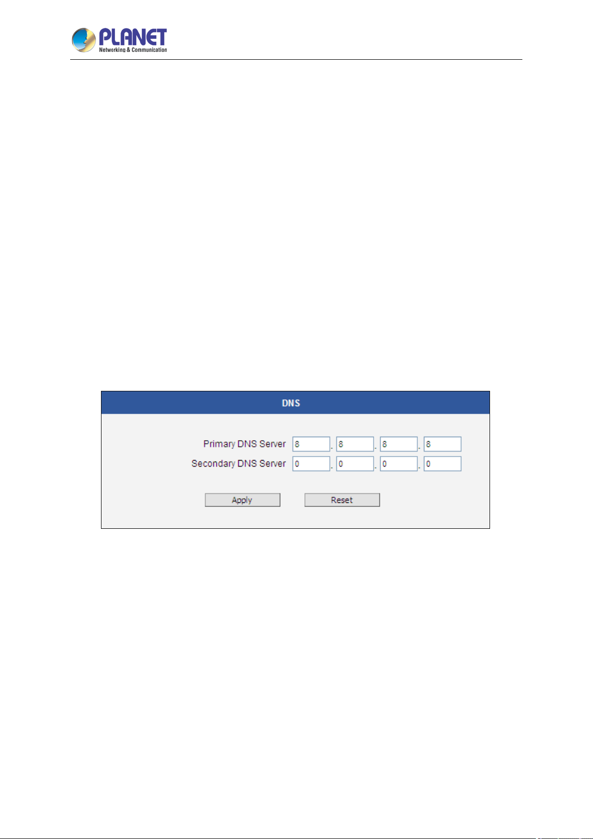
2 Mega-pixel IR PoE Plus Speed Dome IP Camera
71
ICA-E6265
To set the camera in PPPoE mode, set the radio button to PPPoE and key-in the User Name and
Password, provided by Internet Service Provider.
After changing any of the items above, press Apply to save the changes. The Reset button undoes
the changes that had just been made but not Applied yet.
New IP address settings will only take effect after pressing System -> Save & Reboot.
3.9.2 DNS
The DNS section allows setting up the Domain Name Service for the camera. The camera will connect
to the DNS server when there is a need to resolve a domain name for sending data to.
The most common usage is the FTP or e-mail server in the Event Handler section, which is defined by
using domain names. Without having DNS service configured, the camera would not know how to
resolve the domain names of FTP or e-mail servers.
It is possible to configure both Primary and Secondary DNS servers. The Secondary DNS Server will
be used when the connection to the Primary DNS Server fails.
After changing any of the items above, press Apply to save the changes. The Reset button undoes
the changes that had just been made but not Applied yet.
3.9.3 DDNS
There are surveillance solutions that consist of single cameras scattered over a wide territory,
therefore, each of those cameras should be connected to Internet in order to become accessible by
Control Centers, such as chain stores, bus stops, currency exchange booths, etc.
In such cases, one of the practical networking solutions is to use DSL modem on camera site and let
the camera obtain the dynamic IP address from the Internet Service Provider through the DSL modem
using PPPoE connection, which is much more cost-effective than applying for static IP address.
However, there is one dr awback in this solution – in order to do t he remote surveillance from the
Page 72
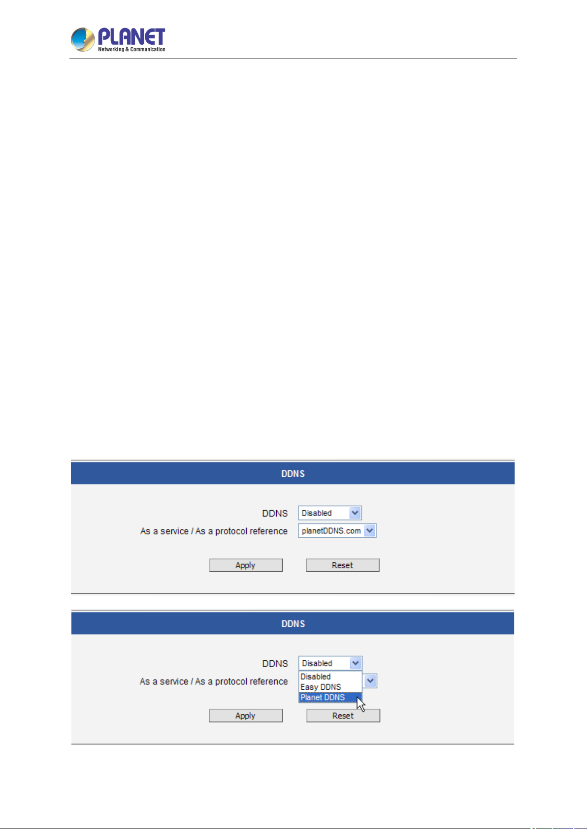
2 Mega-pixel IR PoE Plus Speed Dome IP Camera
72
ICA-E6265
Control Center, the NVR Server in the Control Center has to know the address of the IP camera at all
times in order to get the video stream from the camera. If the camera’s network connection has been
reset for any reason, the camera will get a new IP address through DSL modem, which may be
different from the previous one. NVR will not know about this change, and the connection between the
camera and NVR will fail.
There however exists a solution that makes sure the NVR can find the camera even if the camera IP
changes frequently. Our cameras support Dynamic DNS or DDNS service that allows frequently
changing IP be mapped to a c ertain unchangeable domain name. The mapping database and its
updating engine are hosted in one of the Dynamic DNS servers, the camera supports PLANET DDNS
services for free.
Every time the IP camera gets an IP that is different from previous one, it notifies the public DDNS
Service about the change. The DDNS Service updates its database immediately, mapping the
assigned domain name (for example camera123.planetddns.com) to the new IP address. In NVR
settings, only the domain name (camera123. planetddns.com) is used to identify the camera. Every
time when NVR needs to connect to the camera, it asks from DDNS Service what the current camera’s
IP is. The DDNS Service instantly responds to NVR and tells it the camera’s IP. Now NVR will use the
IP of the camera to connect to the camera and the video stream from the camera to NVR can be
initiated.
As a result, NVR can always find the IP camera regardless of frequently changing IP address of the
camera. Since there are so many public DDNS Services available, the PPPoE-based connection is
really a good and low-cost solution for single-camera sites.
Page 73
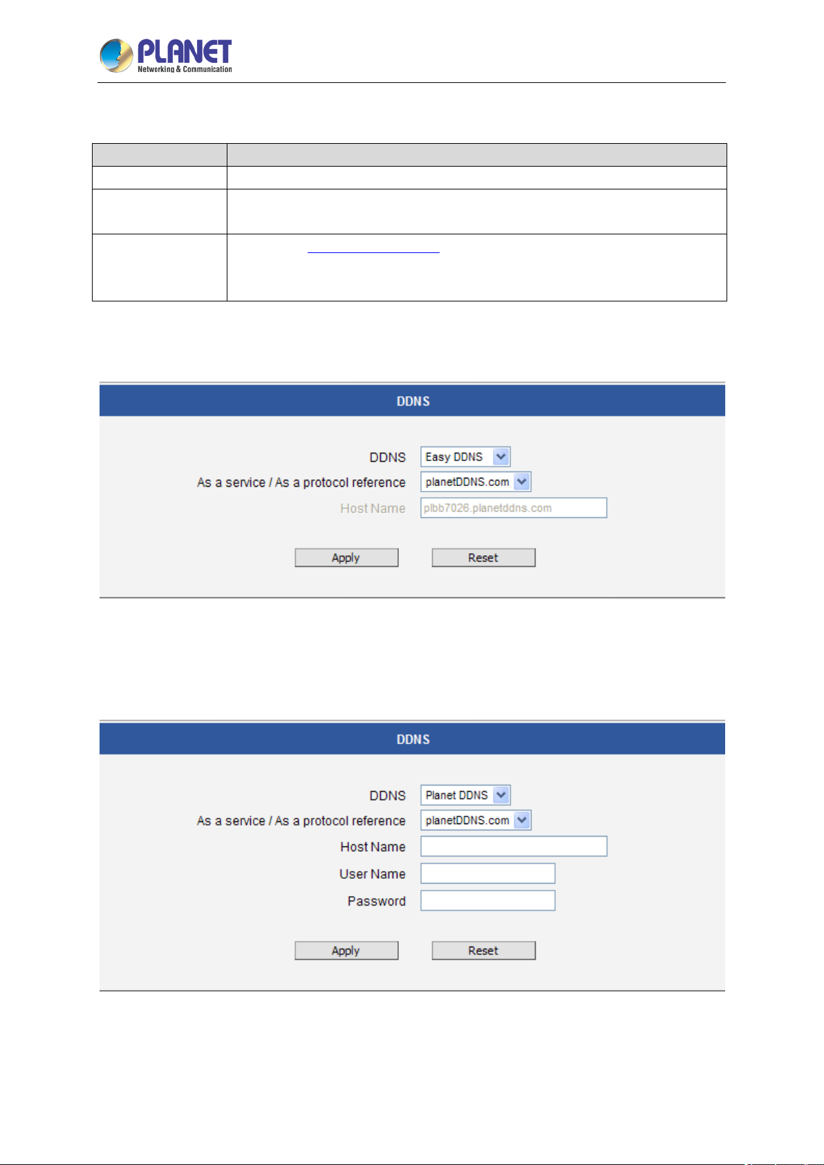
2 Mega-pixel IR PoE Plus Speed Dome IP Camera
73
To activate DDNS, please select the service, such as Easy DDNS or PLANET DDNS.
Parameters Description
Disabled
Easy DDNS
PLANET DDNS
On Easy DDNS page, press Apply to save the changes.
The host name will appear automatically after few seconds.
Disable the DDNS function.
When the function is enabled, it will appear a host name automatically.
User does not need to register an account or host name for your camera.
Please visit
one yet. User will get the needed Host Name, User Name and Password
information from the DDNS service provider
http://planetddns.com and register an account if user does not have
ICA-E6265
Click IP Settings DDNS and the following page will be displayed.
On PLANET DDNS page, you are allowed to modify the DDNS settings.
Page 74

2 Mega-pixel IR PoE Plus Speed Dome IP Camera
74
ICA-E6265
The page includes the following fields:
Parameters Description
DDNS
Host Name
User Name
Password
After changing any of the items above, press Apply to save the changes. The Reset button undoes
the changes that had just been made but not Applied yet.
Select a server provider or disable the DDNS function.
Enter the host name or domain name provided by DDNS provider.
Enter the DDNS user name of the DDNS account.
Enter the DDNS password of the DDNS account.
Page 75
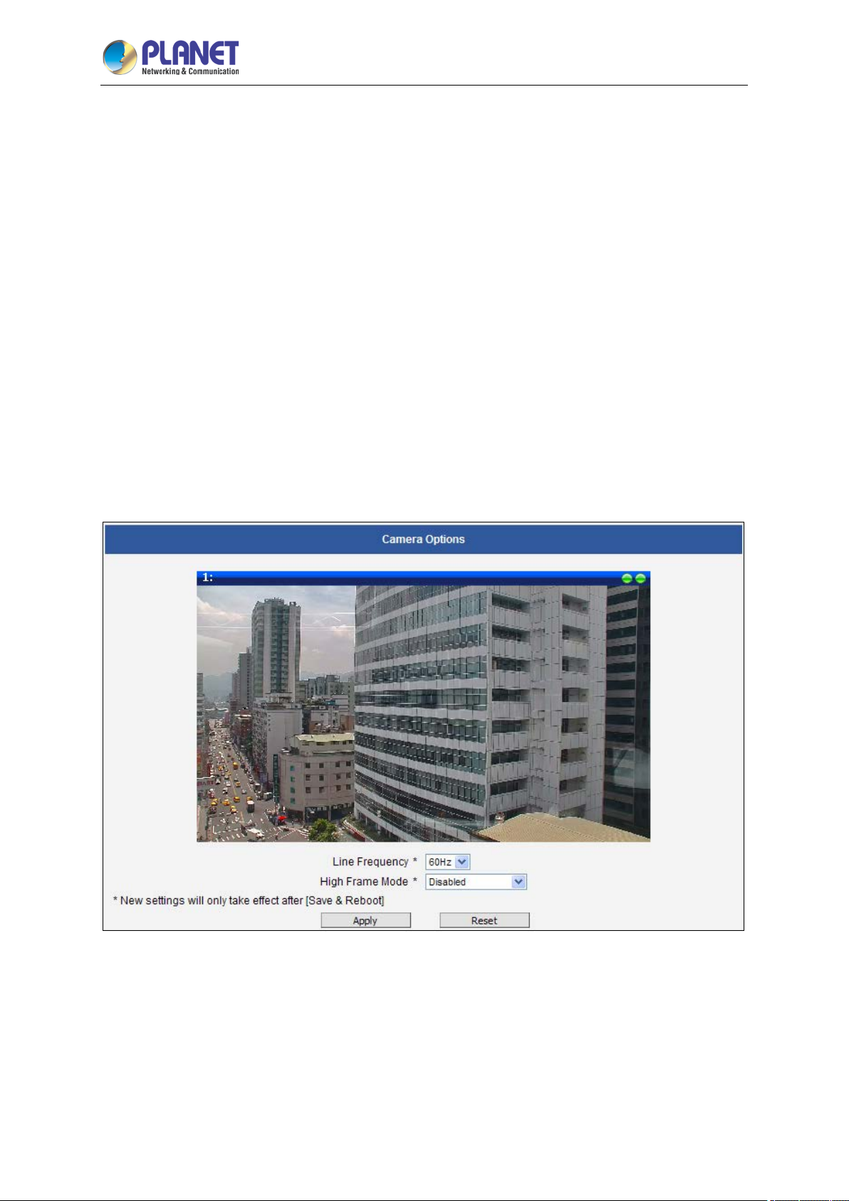
2 Mega-pixel IR PoE Plus Speed Dome IP Camera
75
ICA-E6265
3.10 Video & Audio
The section Video or Video & Audio (for audio supported cameras) provides the options to adjust the
video quality, configure the streaming details of the camera, and audio settings (for Audio supported
cameras only), which will be described on the succeeding pages.
The default settings of the camera are sufficient for most environments and the video adjustments are
not necessary. The following sections explain the ways to configure the video quality or streaming
details in case it is required to do so.
The [+] mark before Video indicates that the list can be expanded by clicking on it. Once expanded,
the list can later be collapsed again by clicking on the [-] mark.
3.10.1 Camera Options
In general, the Camera Options submenu allows users to set the Line Frequency and High Frame
Mode properties of the camera.
Line Frequency is the function that adjusts the shutter speed options to match with the
frequence of artificial light source of given country. For example, in Europe the light frequency
(due to power supply frequency of lights) is 50Hz, that is 50 flashes per second. By setting line
frequency to 50Hz in such case, the shutter speed options will be proportional with light source
frequency, such as 1/25s, 1/50s, 1/100s, etc.
It is necessary to have the camera’s Line Frequency adjusted according to the power
Page 76

2 Mega-pixel IR PoE Plus Speed Dome IP Camera
76
frequency of the light source to avoid flickering effect.
The natural light source (sun light) is a seamless flow of light – the Line Frequency setting does
not matter for the cameras that are only exposed to natural light.
H
igh Frame Mode allows users to select the resolution with 60fps frame rate, where some
deo settings such as Exposure and White Balance, etc. will be automatically configured. This
vi
configuration will be set as the video stream 1 and the original configuration of stream 1 will now
be video stream 2 and so on.
When any of the settings on this page have been modified, click the Apply button and reboot to
make the changes effective.
ICA-E6265
Page 77
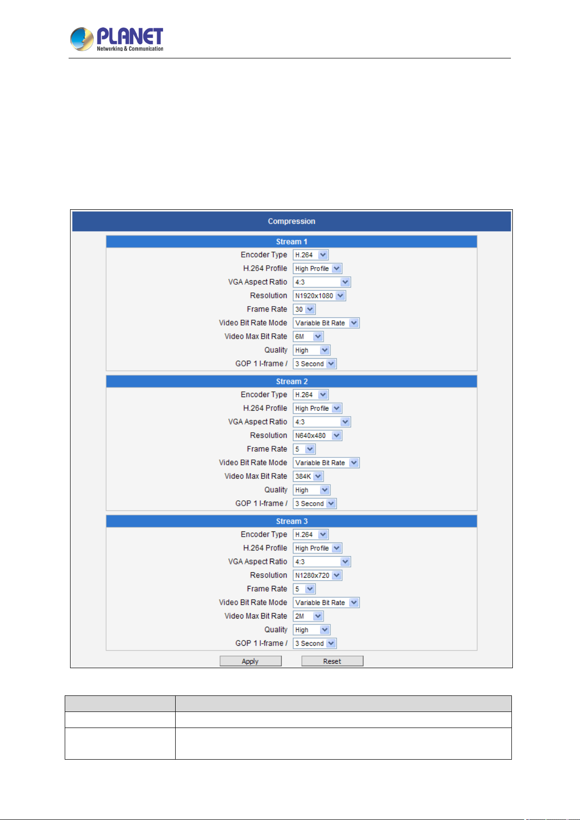
2 Mega-pixel IR PoE Plus Speed Dome IP Camera
77
ICA-E6265
3.10.2 Compression
The Compression section allows the user to define the compression settings of the video streams 1, 2,
and 3. The purpose of compression is to reduce the bandwidth and VMS storage consumption.
Usually the stream 1 is configured to be the best quality stream for NVR recording purposes while the
stream 2 and 3 are configured to be with the basic quality for the live view of NVR or mobile device, to
minimize the computing power of NVR used for video decoding.
Parameters Description
Encoder Type
H.264 Profile
There are two encoder types available: H.264 (High Profile) and MJPEG.
This item is available only if the Encoder Type is H.264. The H.264 Profile
defines the video compression scheme: High Profile, Main Profile, and
Page 78
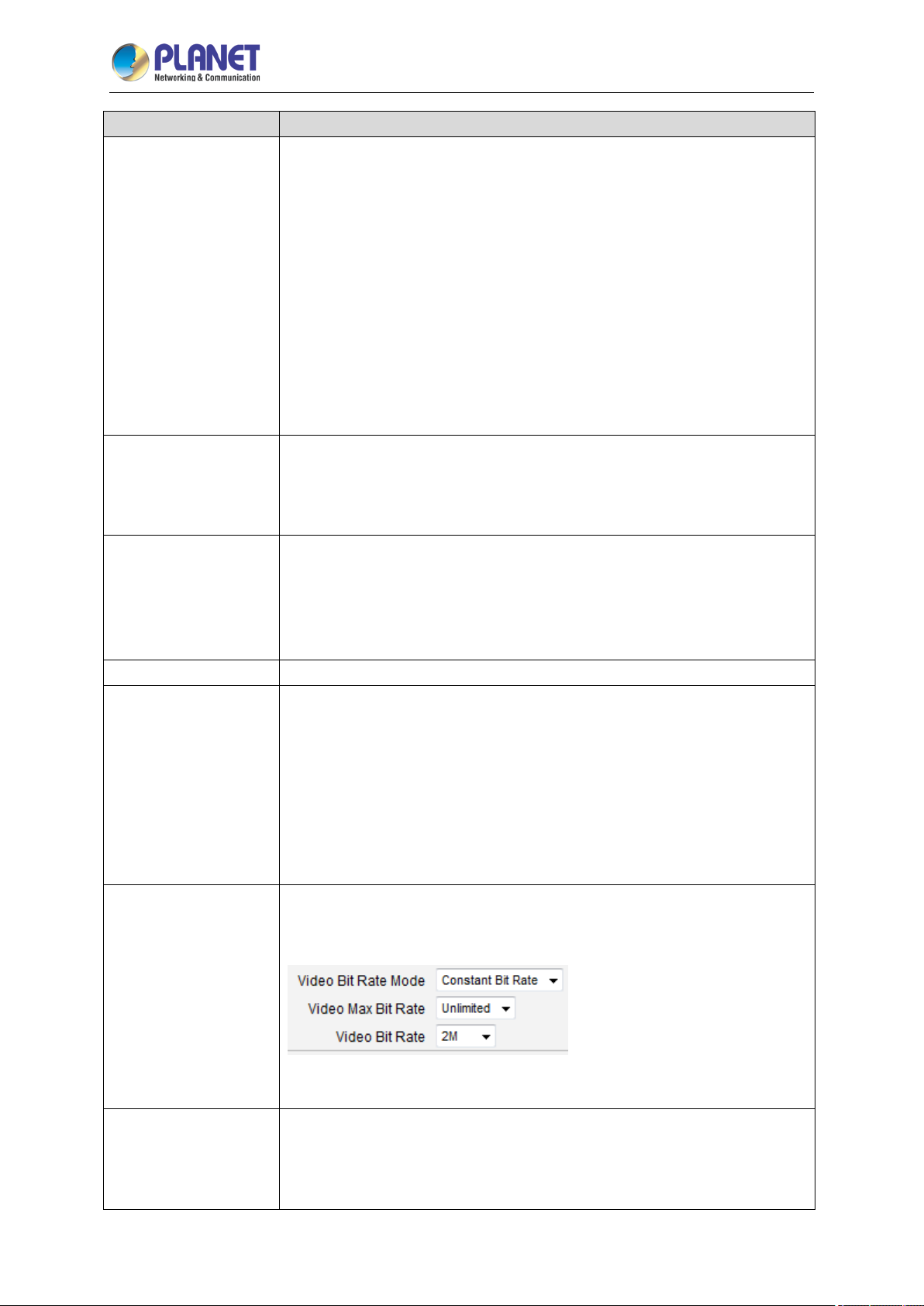
2 Mega-pixel IR PoE Plus Speed Dome IP Camera
78
be different. The default resolution setting of the camera may not
and network bandwidth consumption estimations under this mode
Parameters Description
Baseline. These schemes vary from least compressed, Baseline, to most
compressed, High Profile. By default, the H.264 Profile is High Profile,
which provides the most compression with the best video quality, but more
computing power.
Some third-party video management system has longer latency or takes
more time to decode High Profile compression scheme, in this case, you
can select Main Profile or Baseline. In order to get the same video quality,
you can select a higher bit rate with lower compression; this is the same as
having a lower bit rate with a High Profile. For example, a video on High
Profile with 2M bit rate will have the same video quality as a video with
Baseline Profile at 3.5M bit rate.
It is used to define the aspect ratio of VGA stream – it can be either 4:3 ratio
VGA Aspect Ratio
(640x480) or 16:9 ratio (640x360). When “Auto Detected” is chosen, the
VGA stream will follow the ratio of the higher resolution stream, to ensure
the identical view of stream 1 and stream 2.
Depending on the camera model, the number of available resolutions may
ICA-E6265
Resolution
Frame Rate
Video Bit Rate Mode
(only for H.264)
Video Max Bit Rate
(only for H.264)
necessarily be the maximum resolution of the camera. If the user wants to
use the maximum resolution, it is possible to do i t here. The maximum
possible resolution of stream 2 will be smaller than stream 1.
Defines the amount of frames per second.
Under “Constant Bit Rate” mode (CBR), the camera keeps the stable bitrate
regardless of the complexity of the scene. Under this mode, the video
quality may vary if the bit rate value is set too low. It is easier to do storage
compared to Variable Bit Rate mode.
Under “Variable Bit Rate” mode (VBR), the camera will keep the video
quality stable while the bit rate may occasionally go up or down, depending
on the complexity of the scene.
Defines the upper limit of the bitrate (only available under CBR mode). The
bitrate will be floating slightly under that limit. For example, if the limit is set
as 2M, the bitrate will be floating around 1.6~2.0 Mbps.
If the Video Max Bit Rate is chosen as “Unlimited”, then the “Video Bit Rate”
selection box will appear that defines the bit rate level.
Under CBR mode, when Video Max Bit Rate is chosen “Unlimited”, the user
Video Bit Rate
(only for H.264)
can define the AVERAGE bit rate. For example, if the Video Bit Rate is
chosen 2M, then occasionally, the actual bit rate may go below or beyond
2M, but in the long run, the average bit rate will be very close to 2M. This
Page 79
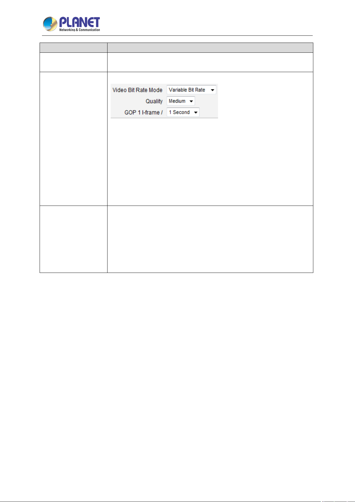
2 Mega-pixel IR PoE Plus Speed Dome IP Camera
79
ICA-E6265
Parameters Description
mode allows the most accurate storage estimations, however, while
planning the bandwidth, please consider the occasional peaks of bit rate.
H.264 Compression:
Under VBR mode, the bit rate will be floating while the video quality will be
Quality
GOP
(only for H.264)
After changing any of the items above, press Apply to save the changes. The Reset button undoes
the changes that had just been made but not Applied yet.
stable and follows the quality standard set by the user. The user can choose
either “High”, “Medium” or “Low” quality. The higher is the quality level, the
more bit rate the camera will use to achieve the target quality.
MJPEG Compression:
The user can define the quality with the numeric scale from 1 to 100. The
default MJPEG quality is 60. The higher is the quality level, the more bit rate
the camera will use to achieve the target quality.
Under VBR mode it is possible to adjust the GOP length - that is the
occurrence rate of I-frames. By default, there is one I-frame per second. For
example, in case of 30fps, there will be 1 I-frame and 29 P-frames every
second by default. When the GOP is changed to “1 I-frame per 5 seconds”,
then there will be o ne I-frame, followed by 149 P-frames. In case of the
static scenes, long GOP can further minimize the bandwidth and storage
consumption.
Page 80
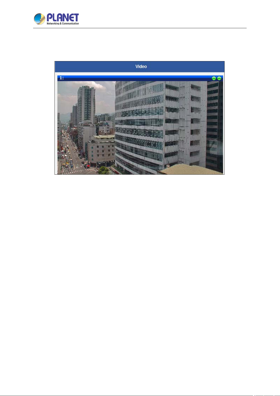
2 Mega-pixel IR PoE Plus Speed Dome IP Camera
80
ICA-E6265
3.10.3 Video
Upon opening the section named Video, the live view of the Stream 1 of the camera will appear.
Usually, Stream-1 is configured to be high quality video with maximum resolution and frame rate for
recording purposes while Stream-2 is usually a moderate quality stream for live view purposes of the
VMS, to reduce VMS computing power during video decoding of multiple channels.
Page 81

2 Mega-pixel IR PoE Plus Speed Dome IP Camera
81
ICA-E6265
Motion Detection
The “Motion Detection” section allows the user to configure the video motion detection system of the
camera. Motion detection regions are based on Stream 1. By default, there are three (3) enabled
pre-defined regions covering the whole camera view.
Click on “Setup” to adjust the motion detection regions or its parameters. Microsoft Internet Explorer
browser is required to configure the motion detection regions.
There are three independently configurable motion detection regions in the camera. Each
motion detection region has 6 configuration parameters:
Enabled or disabled
Location of the region
Size of the region
Sensitivity
Trigger threshold
Trigger interval
Enabled or disabled
Although all 3 motion detection regions are enabled by default, each can be disabled and enabled
individually. Look at the example: Only region 1 is enabled while 2 and 3 are disabled. The disabled
regions disappear from the video display.
Page 82
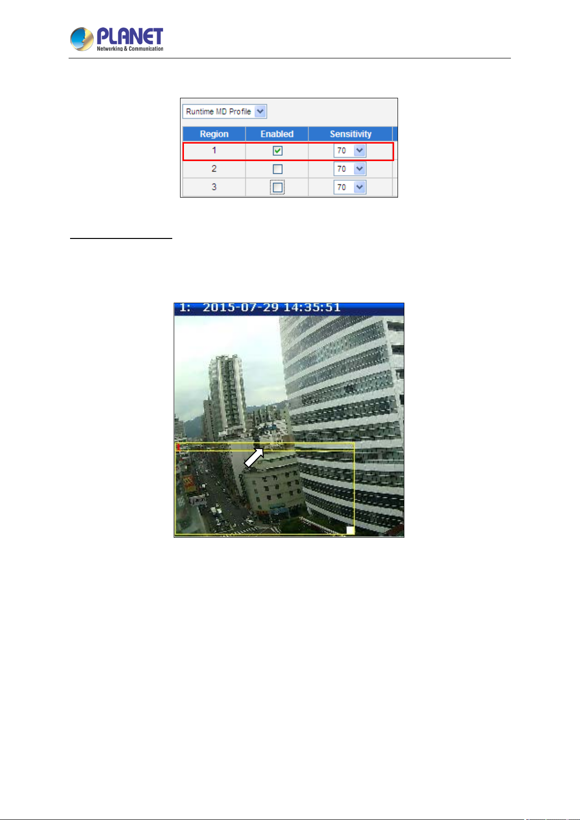
2 Mega-pixel IR PoE Plus Speed Dome IP Camera
82
ICA-E6265
Note that the number of the motion detection region is written in the upper left corner of the region.
Location of the region
You can move the motion detection region anywhere on the field of view by dragging the top of the
motion detection rectangle as shown on the image. The motion detection regions may even be
overlapping if you like.
Page 83
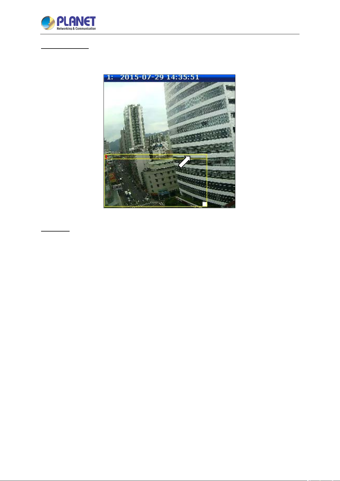
2 Mega-pixel IR PoE Plus Speed Dome IP Camera
83
ICA-E6265
Size of the region
By dragging the lower right corner of the motion detection region you can change the size of the region.
The maximum size of the region can even be as big as the whole screen.
Sensitivity
Sensitivity is the parameter that helps us distinguish actual moving targets (people, vehicles) from the
slightly moving background, such as leaves of the trees waving in the wind. In order to avoid false
alarms, we might want the camera be able to ignore small motion. The higher is the sensitivity level of
the camera the smaller shift of the object is needed to trigger the alarm. For example, if the object
within motion detection region has moved for about 1-3 pixels during two video frames, then such
small motion will be discarded by camera if the sensitivity is low, and will still trigger an alarm if the
sensitivity is high. In other words, you can think of sensitivity level as a reversed speed limit – the
smaller is the sensitivity, the faster are the objects allowed to move without being detected.
The biggest challenge of motion detection configuration is to find the settings that do not produce false
alarms and at the same time do not miss any actual intrusions. The rule of thumb is: the sensitivity
should be as high as possible while not producing false alarms. The default sensitivity level of the
cameras is 70 (on a scale of 0-100) and it is a good setting for most standard cases.
Page 84
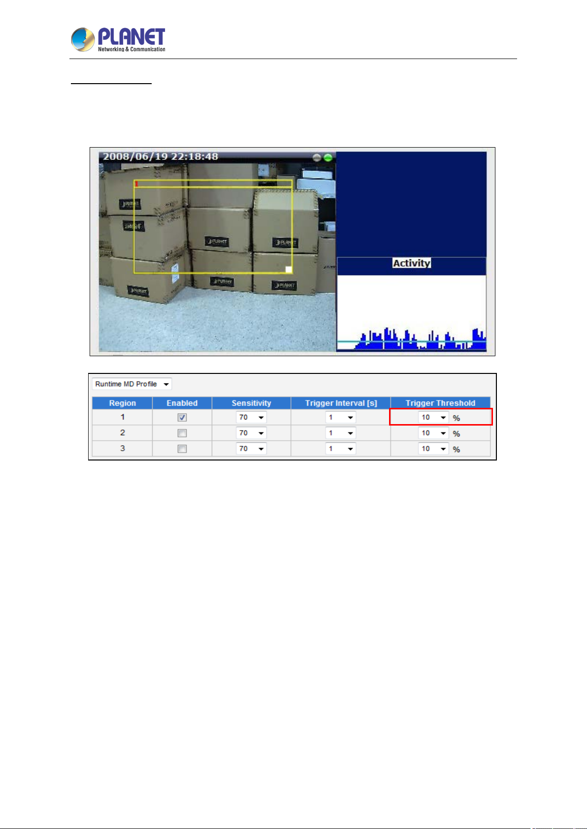
2 Mega-pixel IR PoE Plus Speed Dome IP Camera
84
ICA-E6265
Trigger threshold
Look at the moving object entering the area of motion detection: although moving quite slowly, it
caused motion activity – several pixel regions reported a motion that was faster than allowed “speed
limit” of sensitivity (70).
The blue graph on the right side of the image shows how many percent of pixels within the motion
detection region were considered as “currently in motion”. The activity panel itself is a timeline – for
each moment of time you can see the height of the blue bars. You may notice that at certain moment
the tallest bars in the activity graph reached about 25% (a quarter of the total height in activity panel) –
it means, 25% of this motion detection area were filled with moving pixels at that moment. By visual
observation you can also see that the object standing inside the motion detection region indeed covers
about 25% of its size.
What if the object is really small but moves rather fast (gets triggered by the current sensitivity level)?
For example, we want to detect people but not the cat walking in the room. Although both people and
cat may move with the speed that will trigger motion, they have different size of triggered pixels. For
example, a human passing by the motion detection region will trigger 25% of pixels in that region while
the cat would trigger only 2%. Since we want to have a real alarm in case of human or vehicle passing
by while ignoring birds, cats, butterflies, mice, etc, we need a filter that can define how many percent of
triggered pixels will be considered as a real alarm. This parameter is called trigger threshold. The
default value of trigger threshold is 10%. It means, only the objects that are bigger than 10% of the
motion detection region size and move faster than allowed by sensitivity level (70) will produce actual
alarm.
Page 85
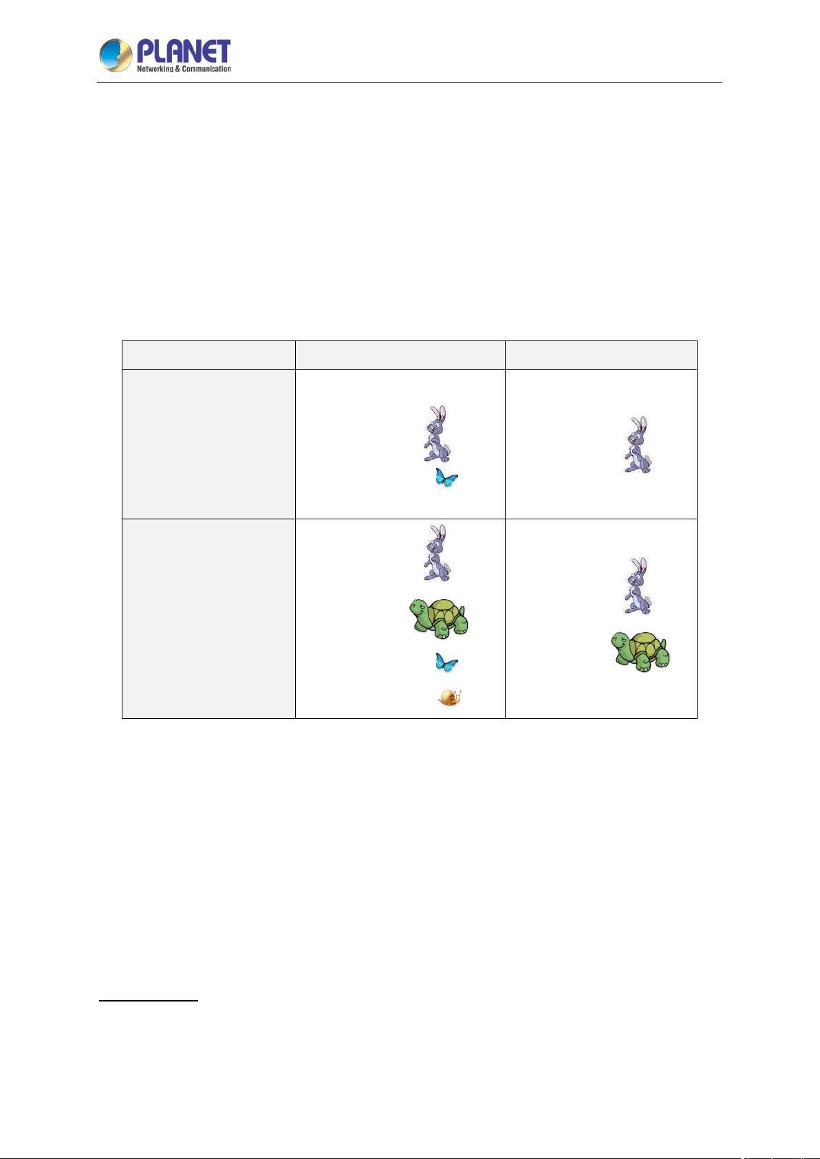
2 Mega-pixel IR PoE Plus Speed Dome IP Camera
85
ICA-E6265
How to choose the most optimal trigger threshold level? The rule of thumb, keep the trigger
threshold as small as possible while not causing false alarms by the moving objects that are
not humans or vehicles.
You c an have a different sensitivity level and trigger threshold level for each motion detection region.
In order to understand all of the above even better, please refer to the table below containing four
possible combinations of settings using sensitivity level and trigger threshold percentage.
The objects listed in each cell will trigger an alarm under given settings:
Low sensitivity
(0-65)
High sensitivity
(65-100)
The camera’s default sensitivity is 70 and threshold is 10%. By these default values, only the
rabbit and the turtle would trigger an alarm while the butterfly and the snail would be ignored by the
motion detection system.
Important: Please remember that changing the size of the motion detection region has an impact on
the threshold – the bigger is the size of the motion detection region the smaller should be the threshold
value if you want the same object size to trigger motion. For example, if you increase the motion
detection region to twice the previous size, please remember to reduce the threshold to half its original
value (from 10% to 5%). On the other hand, changing the location of the motion detection region has
no impact on threshold.
Trigger interval
The last configuration item is the trigger interval. It is the time period from the beginning of the
triggered event during which the all motion activities are ignored by the camera. This is designed to
avoid needless repetitive reporting of the same intrusion. Trigger interval 20 seconds would mean that
Low threshold (0-5%) High threshold (5-100%)
Big and fast
Small and fast
Big and fast
Big and slow
Small and fast
Small and slow
Big and fast
Big and fast
Big and slow
Page 86

2 Mega-pixel IR PoE Plus Speed Dome IP Camera
86
ICA-E6265
when the even happens, camera will take certain one-time actions and ignore the continuing activity in
the motion detection region for 20 seconds. When 20 seconds are over, the camera will produce a new
alarm if there are still action in the motion detection region, and take actions again.
There is one more item on the Motion Detection configuration page which was not explained above –
the Profile of Motion Detection. Think of them as Profile 1 (Runtime MD Profile) and Profile 2
(Event MD Profile). It means that you can configure two independent groups of Motion Detection
regions with at most 3 regions in each group. Normally, the Profile 1 (Runtime MD Profile) is used as
an active profile of the camera. However, in some cases it is possible to let the camera switch to Profile
2 by using the Event Handler system of the camera.
For example, you might want to have different motion detection parameters for day and night time.
Then the two profiles become really handy. In such case, remember to configure the motion detection
parameters for both profiles before moving on to configure the event response system.
After changing any of the items above, press Apply to save the changes. The Reset button undoes
the changes that had just been made but not Applied yet.
Day/Night
The Day/Night section allows user to control the switching between day mode and night mode. This
section will be displayed only for day/night models.
Parameters Description
There are three modes:
Day/Night mode
Auto: The camera will automatically switch between day mode (color) and
night mode (black/white) under certain exposure level, defined by user at
Page 87
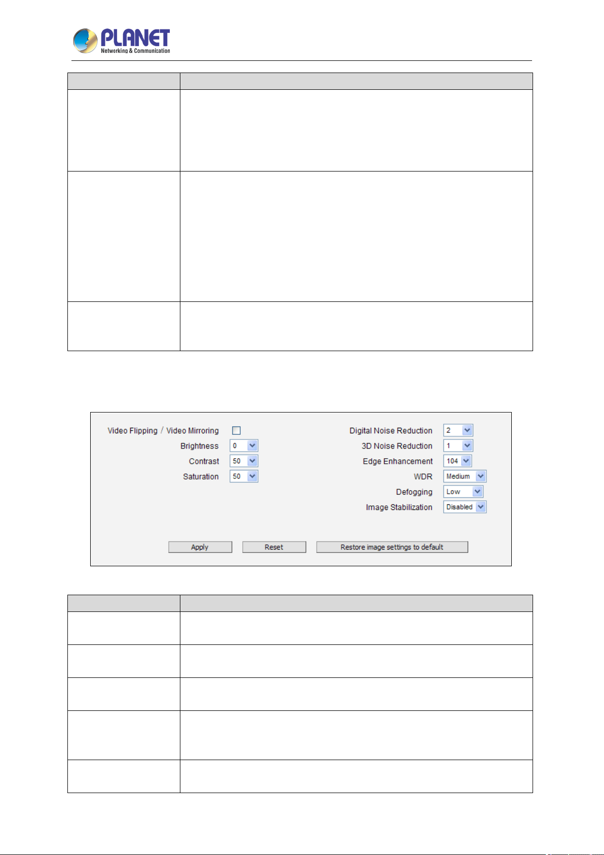
2 Mega-pixel IR PoE Plus Speed Dome IP Camera
87
Video Flipping/Video
Parameters Description
“Switch from Day mode to Night mode”.
Day: The camera always stays in day mode (color) regardless of exposure
level.
Night: The camera always stays in night mode (black/white) regardless of
exposure level.
This feature is visible only in cameras with built-in IR LED.
There are two modes:
Auto: The built-in IR LED will be turned on automatically upon day to night
IR LED Control
Switch from Day mode
to Night mode
Image
The Image section allows user to control certain parameters of a video frame.
switch and turned off upon night to day switch.
Disabled: The IR LED will be off regardless of day and night mode.
Zoom cameras have adaptive IR profile, which means that when IR LED
Control is set to “Auto” (default setting), the IR LED automatically adapts to
the required IR LED power as the camera is zoomed in or out.
The scale of 0~100 allows user define the exposure level at which the day to
night switch should happen. The higher is the value, the darker the
environment has to be to trigger the day to night switch.
ICA-E6265
Mirroring
Brightness
Contrast
Digital Noise
Reduction
3D Noise Reduction
Parameters Description
Check this box to flip the video up-side-down and left-right to achieve the
180-degree rotation effect.
Select the Brightness value (0~100). The higher the value, the brighter the
image.
Select the Contrast level from the following options: Lowest, low, medium,
high, highest.
Turn ON or OFF the Digital Noise Reduction. When turned on, the noise on
the video (especially in low light) is reduced and image will look smoother
and clearer.
Enable this feature for smooth and clear image. Disable this feature if the
scene contains extreme details that may be smoothed over with 3DNR.
Page 88
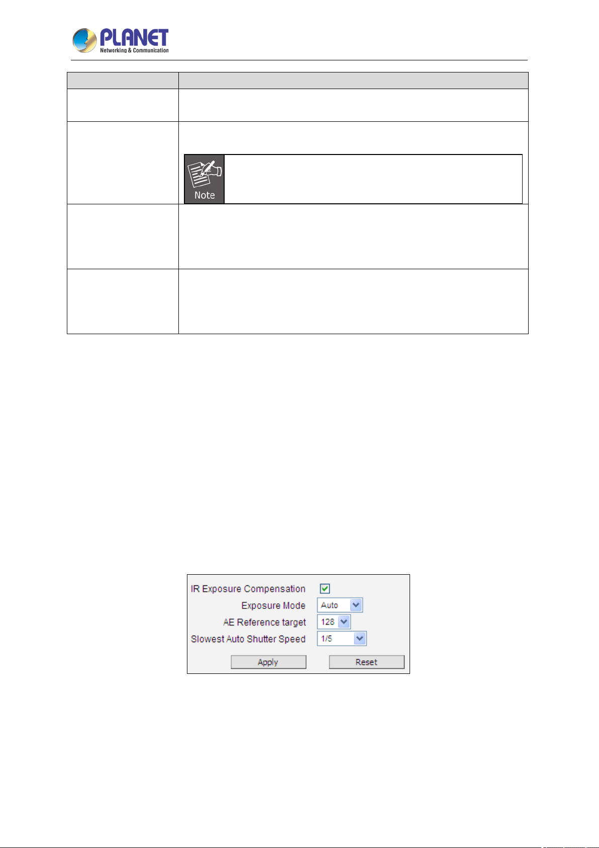
2 Mega-pixel IR PoE Plus Speed Dome IP Camera
88
ICA-E6265
Parameters Description
Select the Edge Enhancement value. The higher the value, the sharper the
Edge Enhancement
image.
Choose the WDR level from following options: Disabled, low, medium, high,
highest.
WDR
WDR is disabled and will not appear on screen if Exposure
Mode is set to “Manual”.
This feature provides a clear image even when the camera is installed in a
Defogging
foggy environment. Select the Defogging level: Disabled, Low, Medium,
High, and Highest. Wherein “Low” is ideal for a slightly foggy environment
and “Highest” for the foggiest environment.
This feature has no obvious effect under normal viewing conditions.
However, if the camera is installed inside a moving vehicle, such as a train,
Image Stabilization
etc., enable this feature to make the image stable even when the
environment is in constant motion.
After changing any of the items above, press Apply to save the changes. The Reset button undoes
the changes that had just been made but not Applied yet.
The button “Restore image settings to default” is a quick way of restoring factory default image
settings without needing to reset the whole camera to factory default.
Exposure/White Balance
The Exposure/White Balance section allows the user to configure Exposure (shutter, iris and gain
control) and White Balance settings. In most cases, the default settings are sufficient and no
adjustment is needed. Some options will only appear under certain Exposure/White balance modes.
Each mode is described in details below.
IR Exposure Compensation - Enabled
IR Exposure Compensation is available on all cameras with IR LEDs. This feature automatically
balances the IR exposure to eliminate over-exposed images cause by too much IR on the subject.
When enabled, the AE reference target is automatically adjusted to control the sensor’s shutter speed
and gain to compensate IR effect.
Page 89
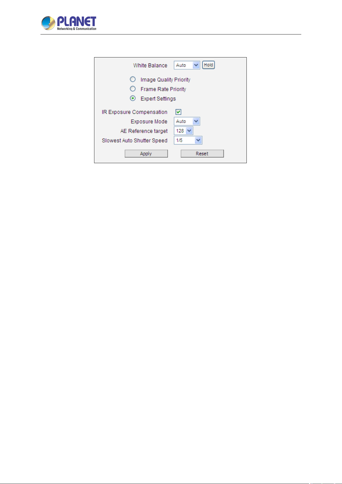
2 Mega-pixel IR PoE Plus Speed Dome IP Camera
89
ICA-E6265
Exposure Mode -Auto
In Auto Exposure Mode, you control the image brightness by configuring the AE Reference Target and
Slowest Auto Shutter.
AE Reference Target (Auto Exposure reference target) can be considered as the “Target Brightness
on Sensor”. The camera will use several internal parameters to achieve best quality with reference to
this. The higher this value, the brighter the overall scene, however, there may be more noise at
night in such case. The range of AE Reference Target is 1~255.
The camera will automatically control shutter speed, auto iris (if available) and signal gain to achieve
the target level set by the user. If the auto iris does not exist or is already opened to a maximum size,
and the image is still darker than the user defined target, it will further slow down the shutter speed
within the allowed range (set by user under Slowest Auto Shutter Speed) and increase the signal gain.
Slowest Auto Shutter Speed is the user defined threshold for slowest allowed speed of auto shutter.
For example, if by default the shutter speed would vary between 1/5s ~ 1/2000s depending on the
lighting conditions, then setting the Slowest Auto Shutter Speed to 1/30s would narrow down the auto
shutter range to work between 1/30s ~ 1/2000s. The purpose of allowing user to define the threshold
for slowest speed is to avoid motion blur caused by too slow shutter at night.
It is also important to know that very high shutter speed is not recommended for indoor solutions with
artificial light that flashes with certain frequency, as it may produce flickering effect, regardless of
Exposure mode.
In extreme low light conditions, the shutter speed is slown down to get more light into one image, but
not slower than the user defined threshold.
If the exposure time extends beyond the interval between frames (too slow shutter), (i.e. 1/30 second),
then the frame rate will be automatically reduced. Longer time in this value gives clearer images at
night for slow moving objects, but more motion blur for fast moving objects.
White balance refers to the capability of the camera to understand what “true white color is”. When
Page 90
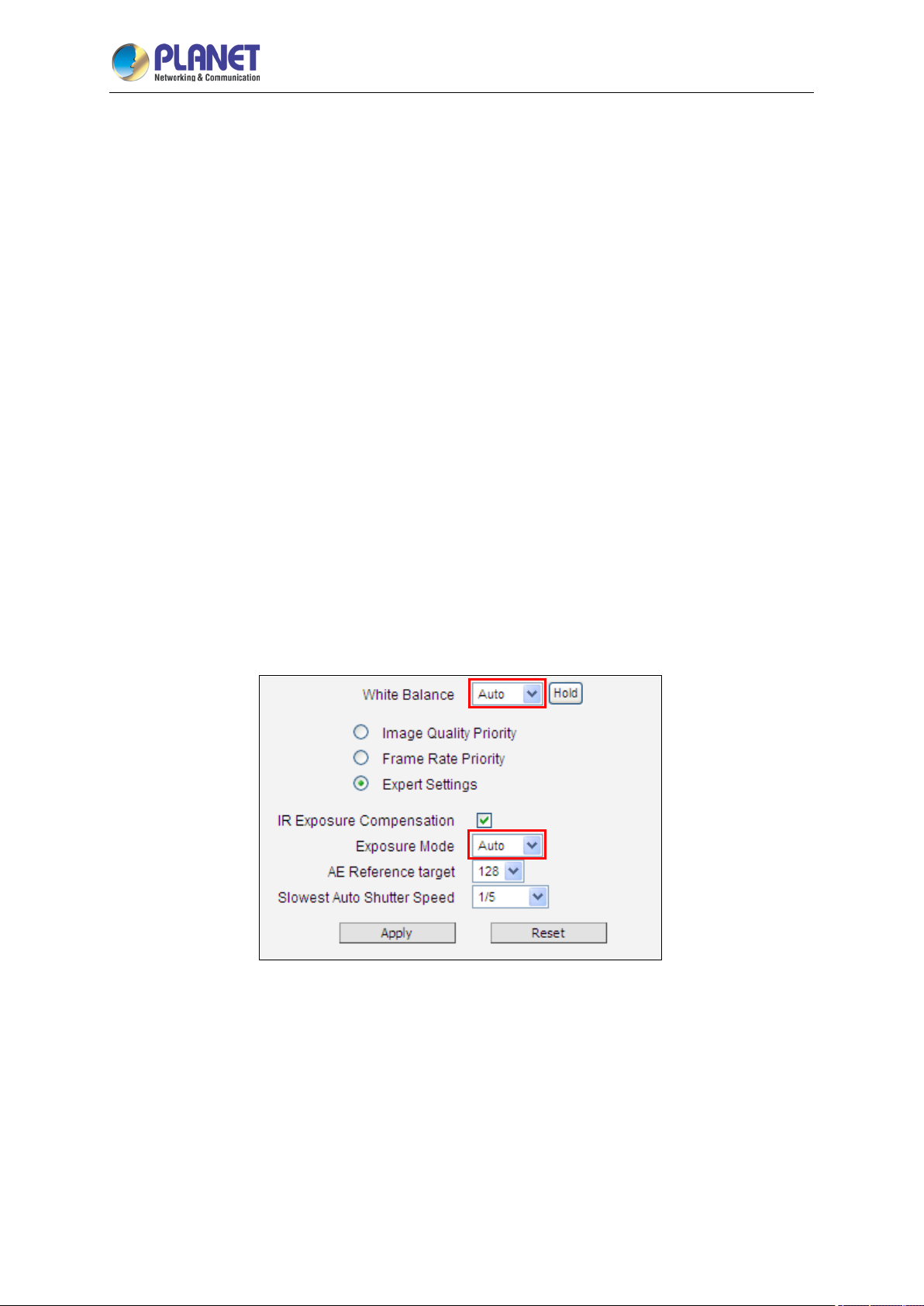
2 Mega-pixel IR PoE Plus Speed Dome IP Camera
90
ICA-E6265
the camera knows the true white color, then the rest of the colors will be accurate, too. While human
eye can easily adapt to different lighting sources (even mixed sources, such as sun light through the
window and indoor lights turned on at the same time), the camera has to understand what is the
dominant light source in given scene and what is the “white color” of such light source.
By default, the camera is in auto white balance mode and attempts to recognize the light source and
its color spectrum automatically and adjusts the image accordingly. This function works continuously in
the background. It is re-evaluated for each frame, to make sure if there is any change in dominant light
source (e.g. the user closes the curtains to block the sun light and turns on the indoor lights).
In most cases the auto white balance works perfectly and the user does not have to adjust anything! In
some rare installation cases, especially when there are no white color objects in the field of view, and
the light sources are mixed, the camera may have difficulty to identify the true white color to fine tune
the rest of the colors.
In such cases, the installer can “help” the camera to understand the true colors by placing a white
object (for example a piece of white paper) in front of the camera to cover the whole field of view and
wait a few seconds – the auto white balance system will adjust the colors until the white paper will
really look white on the display. At that moment, the user can freeze these white balance settings by
pressing the Hold button. After pressing that button, the White Balance will switch from Auto mode to
Manual mode, together with the color values captured at the moment of Hold. The user can now
remove the white object from the field of view, and the colors will stay correct for given scene.
For advanced users, there is also an option to switch from Auto mode to Manual mode of White
Balance directly and input the R Gain and B Gain values manually.
After changing any of the items above, press Apply to save the changes. The Reset button undoes
the changes that had just been made but not Applied yet.
Exposure Mode - Manual
When the lighting conditions are stable 24 hours a day, the advanced users may consider using
manual exposure mode, to further fine tune the image quality in order to fulfill the special project
Page 91
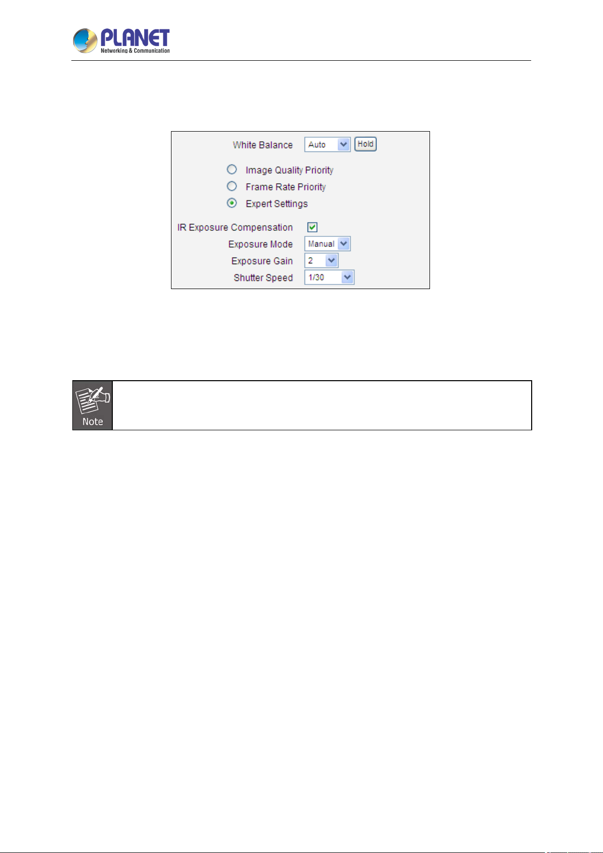
2 Mega-pixel IR PoE Plus Speed Dome IP Camera
91
ICA-E6265
requirements. Please note that in most cases, it is highly recommended to keep the camera in Auto
Exposure mode and let the intelligent system of the camera find the best possible exposure settings
instead.
In manual exposure mode, the user can directly manually adjust the signal Exposure Gain, Shutter
Speed, and even on select models. The White Balance and Line Frequency controls have already
been explained in the previous chapter.
WDR is disabled in manual exposure mode.
After changing any of the items above, press Apply to save the changes. The Reset button undoes
the changes that had just been made but not Applied yet.
OSD/Privacy Mask
The OSD / Privacy Mask section allows user to do one of the two on-video operations:
(1) Add text to the upper or lower left corner of the video. This function is called Text Overlay or
On-Screen Display (OSD). It is possible to display the camera name, date and time, IP address
or any custom text as Text Overlay. The text is kept as small as possible and is not resizable.
The text can be read normally when the video is enlarged on the display to 1:1 ratio. The purpose
of having the text so small is to provide sufficient legal evidence while blocking the smallest
possible area of the video to avoid valuable video evidence being blocked by text overlay. The text
will be embedded into video and cannot be removed later upon playback or export.
(2) Cover up some sensitive areas of the video that should not be captured by the camera, such as
manager’s computer screen or bathroom entrance. This function is called Privacy Mask. It is
possible to configure several independent regions for masking. Microsoft Internet Explorer
browser is required to configure the Privacy Mask. The privacy masks will be embedded into video
and cannot be removed later upon playback or export.
Page 92

2 Mega-pixel IR PoE Plus Speed Dome IP Camera
92
ICA-E6265
Text Overlay (OSD) Setup
It is possible to define up to 4 regions of text. If more than 1 region of text is enabled and positioned in
the same location, then the texts will appear one below another, row by row.
In the example above, one region of text was enabled with blue color and 50% transparency, located
at left lower corner and containing the text of “Office View“ together with current date. The date would
be automatically changing every day, according to camera’s date and time settings. The result of the
example configuration would look like this (Live View page, 1:1 scale):
Below is the list of characters with special meaning that can be used in the text field:
Parameters Description
%YYYY Year in four-digit format. For example, 2008
%YY Year in two-digit format. For example, 08
%MM Month in two-digit format. For example, 01 for January, 12 for December
%DD Date in two-digit format. 01~31
%hh Hour in two-digit format. 00~23. Note that only 24-hour indication is supported.
%mm Minutes in two-digit format. 00~59
%ss Seconds in two-digit format. 00~59
%H a hyphen, "-"
%C a colon, ":"
%X a slash, "/"
%N show Camera Name (It might be truncated if exceeds max OSD length)
After changing any of the items above, press Apply to save the changes. The Reset button undoes
the changes that had just been made but not Applied yet.
Privacy Mask Setup
This function puts blocks over parts of the cameras view that should not been seen.It is possible to set
up up to 4 regions of privacy masks. The adjustment of the privacy mask region can be done when
Page 93
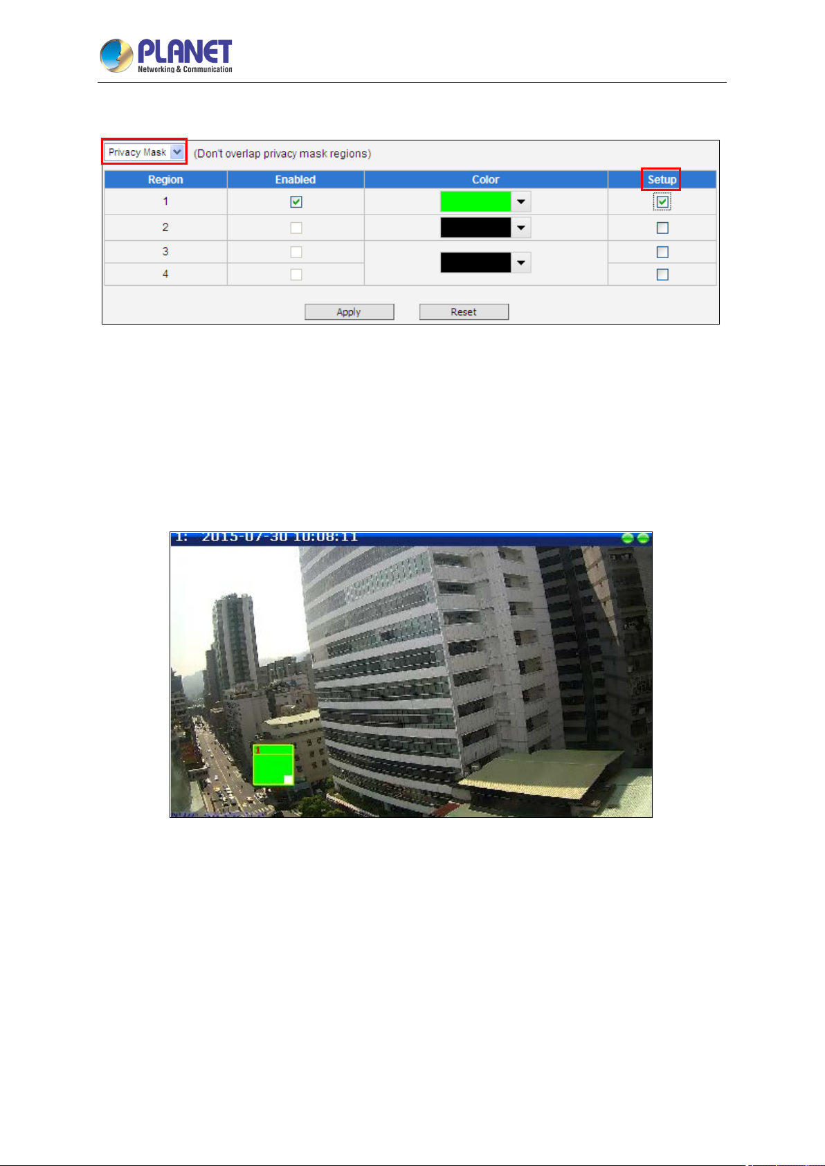
2 Mega-pixel IR PoE Plus Speed Dome IP Camera
93
ICA-E6265
region is checked under “Setup“ column.
You may resize and drag the region the same way as the motion detection regions: upper bar that
contains the number of the region can be used for dragging the region across the video while the white
box at the right lower corner of the privacy mask region can be used for resizing the region.
There are 4 pr e-defined color options for privacy masks. If the user wants to use any other colors,
please use URL commands to set up the privacy mask instead. To do that, please refer to the Guide
that explains the use of URL commands.
Page 94

2 Mega-pixel IR PoE Plus Speed Dome IP Camera
94
When switching back to live view, the privacy mask would look like this:
ICA-E6265
Please note that the Text Overlay (OSD) and Privacy Masks will take effect for both Stream 1 and
Stream 2.
After changing any of the items above, press Apply to save the changes. The Reset button undoes
the changes that had just been made but not Applied yet.
It may take several seconds to update the region location on video display after pressing
Apply!
3.10.4 Audio
The Audio section is available only for audio-supported models. The user interface for audio control
looks like below:
Parameters Description
Audio In The option “Enabled” would activate incoming audio (either line in or built-in
Page 95
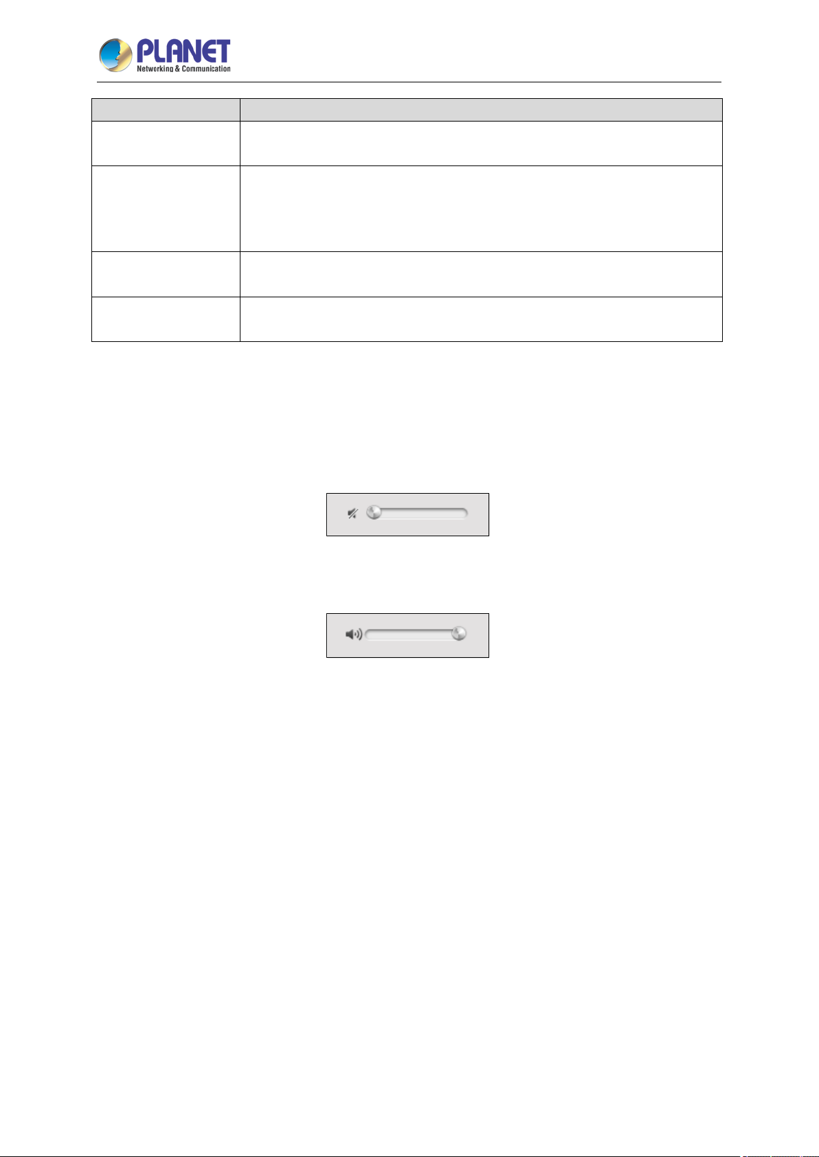
2 Mega-pixel IR PoE Plus Speed Dome IP Camera
95
Parameters Description
microphone). The option “Disabled” would turn off the coming audio. In such
case, the video stream is captured without audio.
Choose “High” when the target is farther away from the camera and choose
Audio In Level
“Low” when the target is near the camera. Under “High” mode, there may be
more audio noise due to higher level of signal amplification.
ICA-E6265
Audio Out Volume
Audio Format
To adjust the volume level of the speakers connected to the PC that runs the Web Configurator in
order to hear the audio from the camera’s microphone or line-in device, go to Live View page and use
the audio controls there:
Audio Muted:
Audio level adjusted to the maximum:
The audio out volume level can be adjusted in the scale of 0-100. It will
influence the volume level of the speakers connected to the camera.
Choose the compression format of audio: PCM, G.711A (A-law) or G.711U
(µ-law).
This volume control appears in user interface only when the Audio-in function of the camera has been
“Enabled”.
Page 96
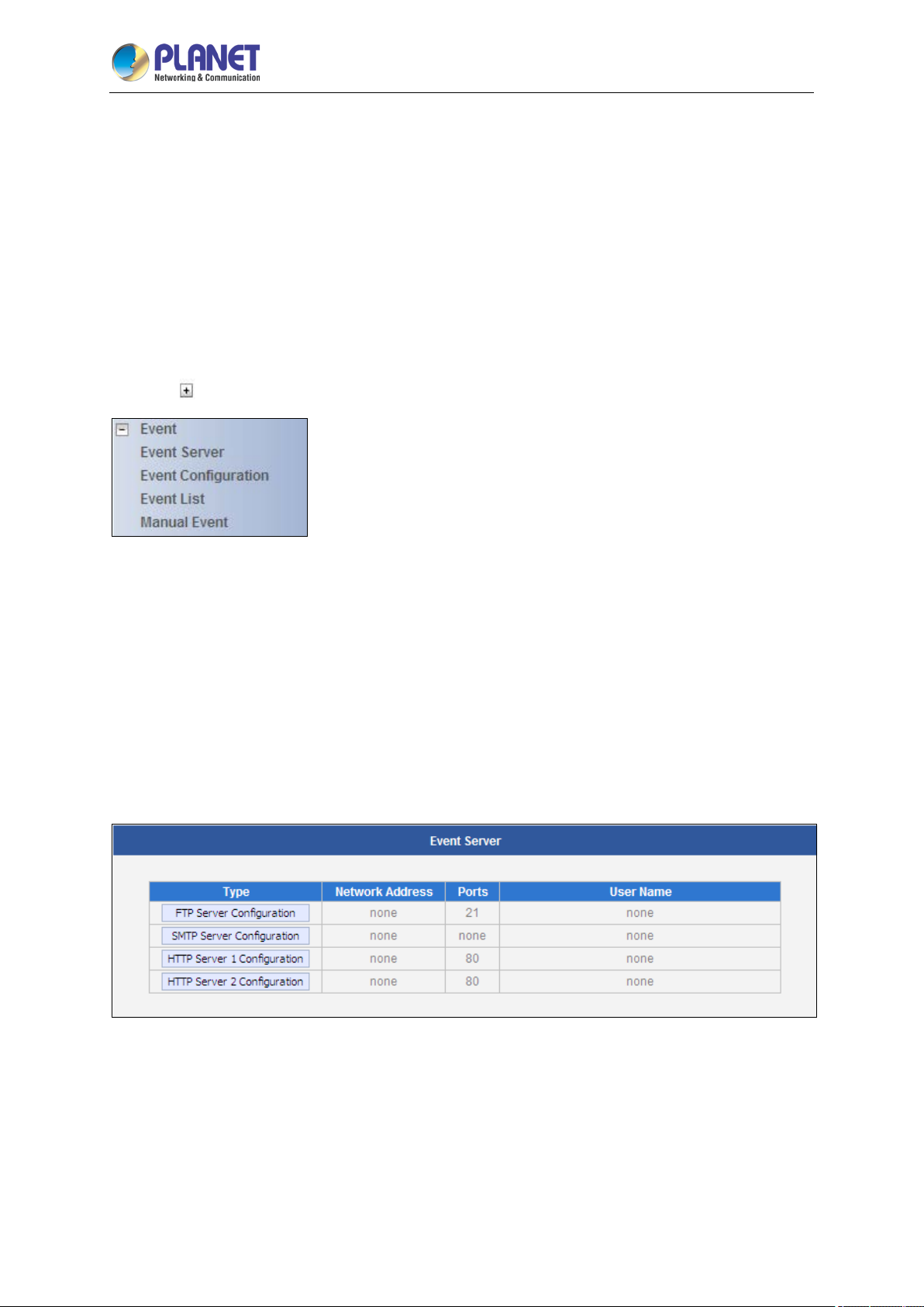
2 Mega-pixel IR PoE Plus Speed Dome IP Camera
96
ICA-E6265
3.11 Event
This section describes how to set up the Event Handler, which deals with how the IP devices respond
to situations. Each IP device can have a maximum of 10 Event Rules. Each rule includes one single
trigger, and one or many responses. Several types of responses are available. And there are multiple
external servers for the device to interact with.
When setting up Event Handler, there are four types of settings. Event Server, Event Configuration,
Event List and Manual Event
Click the
item before Event to expand the list.
3.11.1 Event Server
Event servers define whom the device may interact with. They can be other servers or devices on the
network, or even the camera itself. Event Configuration sets up a list of what to tell the other party
during interaction. Event list lays down the rules and conditions about when to initiate which responses
from which triggers. The o ptions available for Event rules a re selected from the event servers
and event configurations.
Event servers are classified as FTP servers, SMTP servers and HTTP servers
Page 97
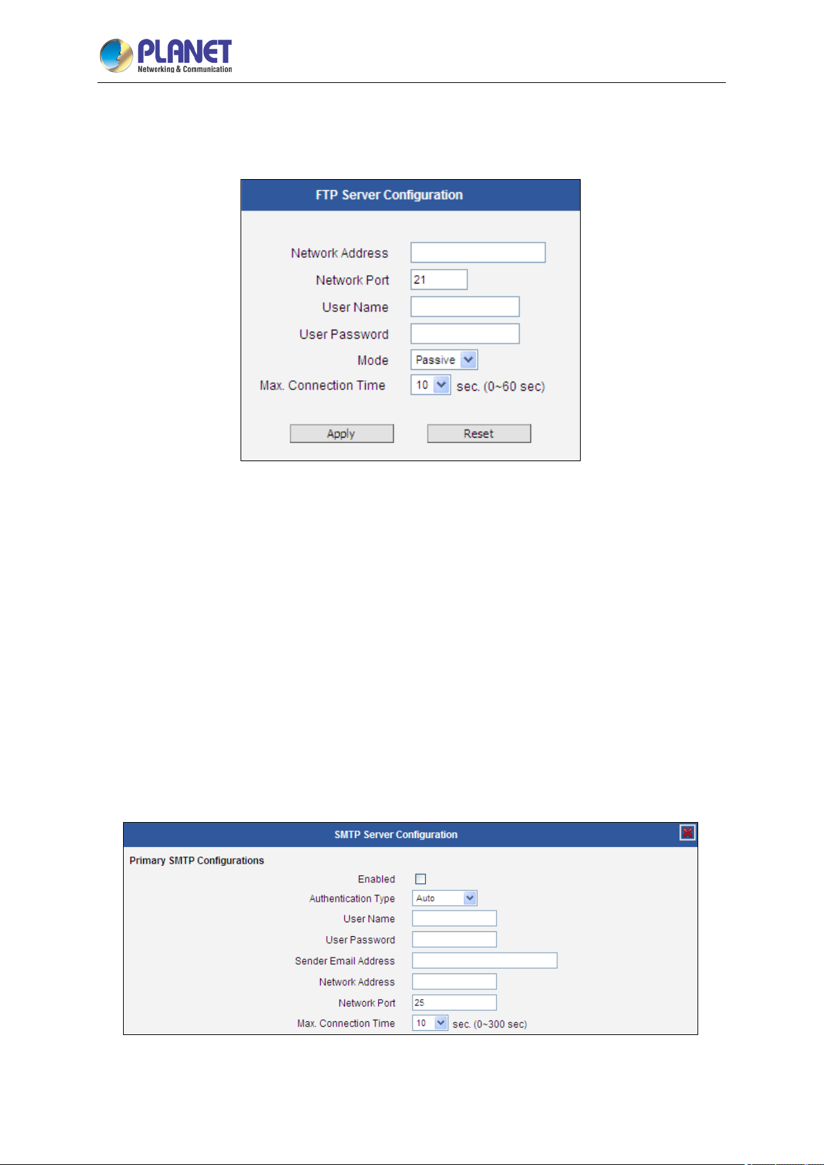
2 Mega-pixel IR PoE Plus Speed Dome IP Camera
97
ICA-E6265
FTP Server
FTP servers can receive snapshot or video uploads that are issued as part of the response from event
handlers. You may set up one FTP server.
To set up FTP servers, make sure to enter the network address of FTP server, the Network (FTP) port,
the User Name and Password of FTP account, Connection mode (Passive or Active) and Connection
time before timeout.
After changing any of the items above, press Apply to save the changes. The Reset button undoes
the changes that had just been made but not Applied yet.
SMTP Server
SMTP servers can send email upon request from the IP device. The email can be a simple subject
and text email, or attached with snapshot/video. You may set up two SMTP servers. The device will
first attempt to send the message via the Primary email SMTP server. If the first attempt fails (after the
maximum connecting time), the device will attempt to send it via the secondary SMTP server. If the
device sends email successfully via the primary SMTP server, then it will not use the secondary SMTP
server.
To set up SMTP servers, make sure to enable the SMTP account and choose the proper
Page 98
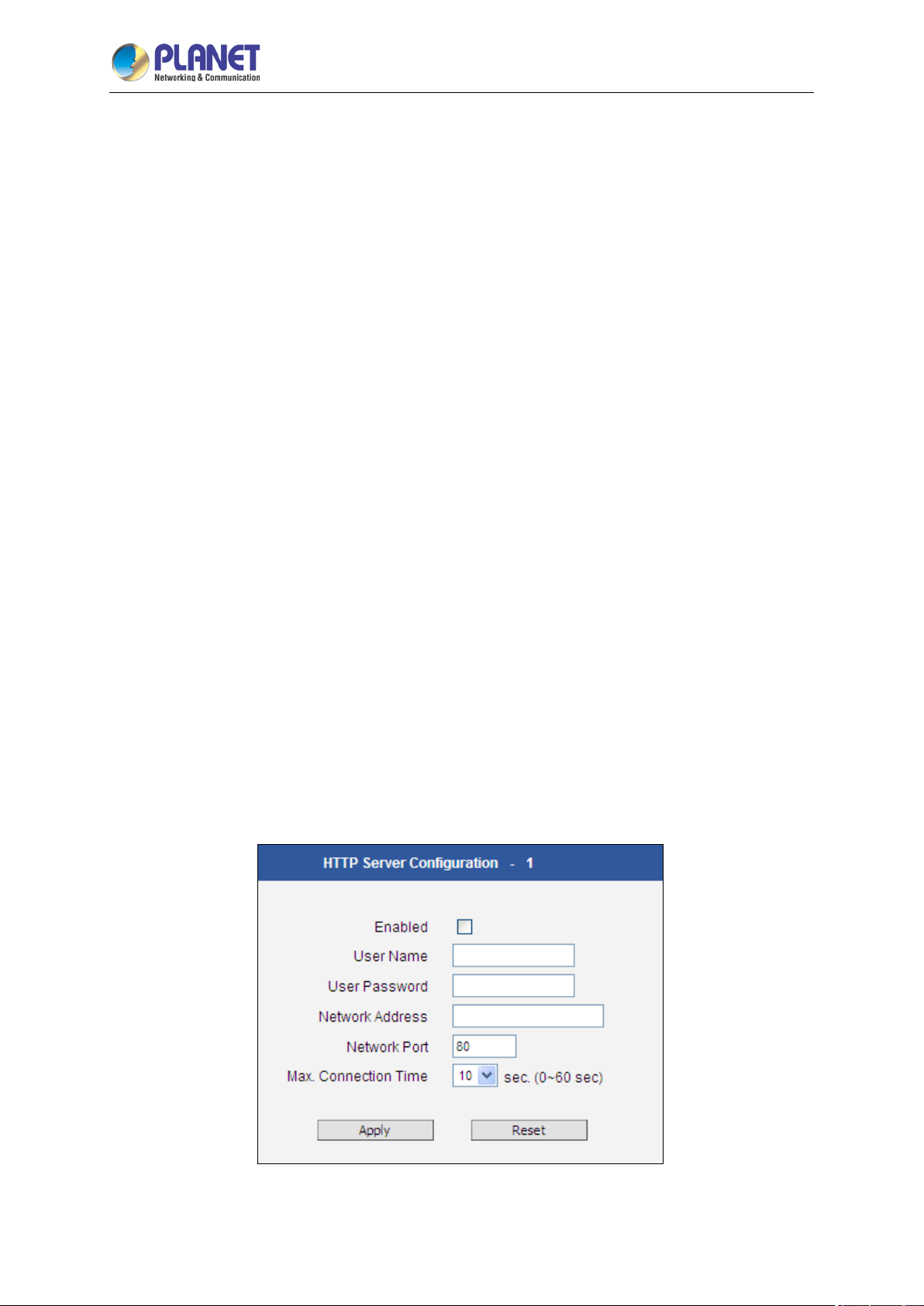
2 Mega-pixel IR PoE Plus Speed Dome IP Camera
98
ICA-E6265
Authentication type. There are many types available. The default is Login. We recommend you to use
Auto Detection. Available authentication types include: Auto Detection, None, Login, Plain, Cram MD5,
Digest MD5 and PoP Relay. Please also enter the User Name, Password, the email address displayed
as sender (can be different than the user name), Network (SMTP server) address, Network (SMTP
server) Port number and Max Connection time before timeout (in seconds).
After changing any of the items above, press Apply to save the changes. The Reset button undoes
the changes that had just been made but not Applied yet.
HTTP Server
HTTP CGI servers are programs that run on web sites or many devices. They can be
custom-programmed to perform a large variety of actions based upon the input. You can define which
CGI server to connect to here, and the user / password required to log into the target server. The
actual message/command is setup in the Notification messages/URL commands section. You may
define two separate CGI servers.
IP devices are also CGI servers. This means that IP devices can now issue commands to each other,
which creates endless possibilities for highly coordinated response. The IP device can also give a
loopback command to itself, in effect changing almost all possible settings dynamically. For details on
the commands used to control the cameras, please contact your customer representative.
An example will help you gain a better sense of how to utilize this unique function. Camera A is a fixed
camera that looks at a corridor leading to the main hall. It has a motion detection window located near
the point where the corridor arrives at the large hall. Camera B is a PTZ camera located in the hall,
which is usually left on auto-tour patrol. When motion activity in the motion detection region triggers
MD1 in Camera A, this then in turn activates an event rule in Camera A that gives out a command to
Camera B. Camera B would then swivel to the preset point where the corridor leads into the entrance
and switch to higher bit rate to temporarily provide clearer image. After the event ends, Camera B will
go back to its normal routine in lower bit rate.
To set up HTTP servers, make sure to enable the HTTP server, enter the user name, the user
Page 99
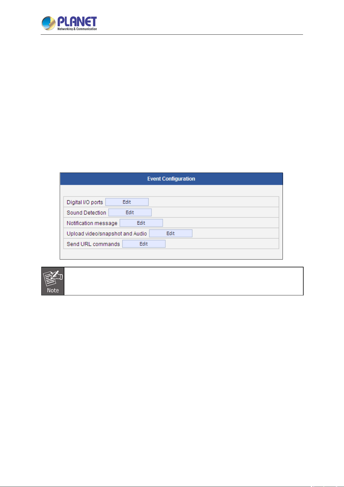
2 Mega-pixel IR PoE Plus Speed Dome IP Camera
99
ICA-E6265
password, Network (HTTP Server) address, Network (HTTP Server) port number and Max connection
time before timeout (in seconds).
After changing any of the items above, press Apply to save the changes. The Reset button undoes
the changes that had just been made but not Applied yet.
3.11.2 Event Configuration
Event configurations are the responses to be performed when an event is triggered. For most types
of responses, you can create several different preset responses, then mix and match in event rules.
The configurable responses are classified as Digital I/O ports, Notification messages, Upload
Video/Snapshot and Audio and Send URL Commands.
Digital I/O ports appear only for the camera models that support this function.
Page 100
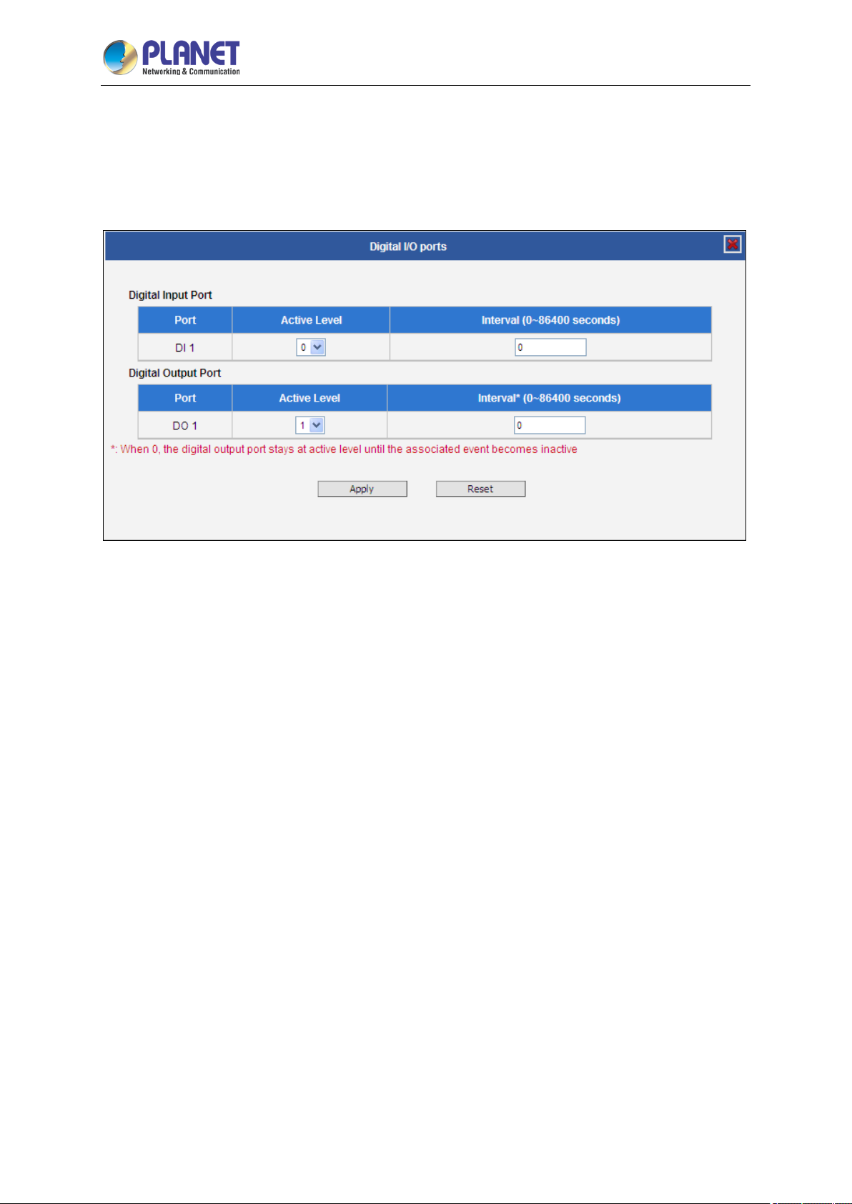
2 Mega-pixel IR PoE Plus Speed Dome IP Camera
100
ICA-E6265
Digital I/O ports
Digital input/output ports (select models only) are used to connect digital input (DI) and digital output
(DO) devices. DI is a trigger device like a switch or sensor (e.g., “panic button”), which when pressed
or triggered, notifies the camera to perform specific actions or the DO device to respond. DO’s can be
alarms or lights, etc.
The Digital I/O Ports page displays the number of available DI and DO ports on the camera, which
varies depending on camera model.
DI: To configure the digital input device, define the active level and trigger interval of the DI. The
default Active Level is “0”, which means the DI device remains inactive unless triggered. A good
example is a “panic button”, which always stays in inactive mode “0” until the button is pressed; when
the button is pressed, its active level becomes “1” which means the DI is triggered. Active level “1”
returns back to “0” (inactive mode) after the specified Interval. The Interval is the duration of time
when the trigger remains in active mode which is also the minimum time interval between the previous
trigger and the next. For example, if the interval is set to “5 seconds”, the DI will not respond if the
“panic button” is pressed within 3 seconds after the previous trigger. To issue another trigger, press the
button after 5 seconds from the previous trigger.
DO: To configure the digital output device, define the active level and response interval. The default
Active Level is “1”, which means the DO will turn to active mode and respond once triggered. The
duration of its response will last according to the set Interval. A good example is an alarm siren,
wherein the siren will start sounding only when it is triggered by an event or another device like a DI.
The siren will stop sounding once the set interval time elapsed.
After changing any of the items above, press Apply to save the changes. The Reset button undoes
the changes that had just been made but not yet applied or saved.
Sound Detection
Sound detection is available on cameras with Audio in capability and is shown on the user interface
 Loading...