

Page 1
User Manual of FRT-405N
1
Page 2

right
Copy
Copyright 2013 by PLANET Technology Corp. All rights reserved. No part of this publication may be
reproduced, transmitted, transcribed, stored in a retrieval system, or translated into any language or
computer language, in any form or by any means, electronic, mechanical, magnetic, optical, chemical,
manual or otherwise, without the prior written permission of PLANET.
PLANET makes no representations or warranties, either expressed or implied, with respect to the contents
hereof and specifically disclaims any warranties, merchantability or fitness for any particular purpose. Any
software described in this manual is sold or licensed "as is". Should the programs prove defective following
their purchase, the buyer (and not this company, its distributor, or its dealer) assumes the entire cost of all
necessary servicing, repair, and any incidental or consequential damages resulting from any defect in the
software. Further, this company reserves the right to revise this publication and to make changes from time
to time in the contents hereof without obligation to notify any person of such revision or changes.
All brand and product names mentioned in this manual are trademarks and/or registered trademarks of their
respective holders.
Federal Communication Commission Interference Statement
This equipment has been tested and found to comply with the limits for a Class B digital device,
pursuant to Part 15 of FCC Rules. These limits are designed to provide reasonable protection
against harmful interference in a residential installation. This equipment generates, uses, and
can radiate radio frequency energy and, if not installed and used in accordance with the instructions, may
cause harmful interference to radio communications. However, there is no guarantee that interference will not
occur in a particular installation. If this equipment does cause harmful interference to radio or television
reception, which can be determined by turning the equipment off and on, the user is encouraged to try to
correct the interference by one or more of the following me
1. Reorient or relocate the receiving antenna.
2. Increase the separation between the equipment and receiver.
3. Plug the equipment into an outlet on a circuit different from that to which the receiver is connected.
4. Consult the dealer or an experienced radio technician for help.
asures:
FCC Caution:
To assure continued compliance, (example-use only shielded interface cables when connecting to computer
or peripheral devices) any changes or modifications not expressly approved by the party responsible for
compliance could void the user’s authority to operate the equipment.
This device complies with Part 15 of the FCC Rules. Operation is subject to the Following two conditions:
2
Page 3

(1) This device may not cause harmful interference
(2) This Device must accept any interference received, including interference that may cause undesired
operation.
Federal Communication Commission (FCC) Radiation Exposure Statement
This equipment complies with FCC radiation exposure set forth for an uncontrolled environment. In order to avoid the
possibility of exceeding the FCC radio frequency exposure limits, human proximity to the antenna shall not be less than
20 cm (8 inches) during normal operation.
R&TTE Compliance Statement
This equipment complies with all the requirements of DIRECTIVE 1999/5/CE OF THE EUROPEAN PARLIAMENT AND
THE COUNCIL OF 9 March 1999 on radio equipment and telecommunication terminal Equipment and the mutual
recognition of their conformity (R&TTE).
The R&TTE Directive repeals and replaces in the directive 98/13/EEC (Telecommunications Terminal Equipment and
Satellite Earth Station Equipment) As of April 8, 2000.
Safety
This equipment is designed with the utmost care for the safety of those who install and use it. However, special attention
must be paid to the dangers of electric shock and static electricity when working with electrical equipment. All guidelines
of this and of the computer manufacture must therefore be allowed at all times to ensure the safe use of the equipment.
National Restrictions
This device is intended for home and office use in all EU countries (and other countries following the EU
directive 1999/5/EC) without any limitation except for the countries mentioned below:
Country Restriction Reason/remark
Bulgaria None
Outdoor use limited to 10
France
Italy None
Luxembourg None
Norway Implemented
Russian Federation None Only for indoor applications
mW e.i.r.p. within the band
2454-2483.5 MHz
General authorization required for outdoor use and
public service
Military Radiolocation use. Refarming of the 2.4 GHz
band has been ongoing in recent years to allow current
relaxed regulation. Full implementation planned 2012
If used outside of own premises, general authorization is
required
General authorization required for network and service
supply(not for spectrum)
This subsection does not apply for the geographical area
within a radius of 20 km from the centre of Ny-Ålesund
3
Page 4

WEEE regulation
To avoid the potential effects on the environment and human health as a result of the presence of
hazardous substances in electrical and electronic equipment, end users of electrical and electronic
equipment should understand the meaning of the crossed-out wheeled bin symbol. Do not dispose
of WEEE as unsorted municipal waste; WEEE should be collected separately.
sion
Revi
User’s Manual for 802.11n Wireless Internet Fiber Router
Model: FRT-405N
Rev: 2.0 (August, 2013)
Part No. EM-FRT-405N_v2 (2080-B53060-000)
User Manual of FRT-405N
4
Page 5

User Manual of FRT-405N
Table of Contents
CHAPTER 1.PRODUCT INTRODUCTION....................................................................................................... 8
1.1 Package Contents .............................................................................................................. 8
1.2 Product Description ........................................................................................................... 9
1.3 Product Features.............................................................................................................. 10
1.4 Product Specifications..................................................................................................... 12
CHAPTER 2. HARDWARE INSTALLATION ................................................................................................. 14
2.1 Hardware Description ...................................................................................................... 14
2.1.1 Front Panel of FRT-405N......................................................................................................... 14
2.1.2 LED Indications of FRT-405N .................................................................................................. 14
2.1.3 Rear Panel of FRT-405N ......................................................................................................... 15
2.2 Cabling .............................................................................................................................. 16
2.2.1 Installing the SFP Transceiver ................................................................................................. 16
2.2.2 Removing the Module .............................................................................................................. 17
CHAPTER 3. CONNECTING TO THE ROUTER ........................................................................................... 19
3.1 System Requirements...................................................................................................... 19
3.2 Installing the Router......................................................................................................... 19
CHAPTER 4. INSTALLATION GUIDE ........................................................................................................... 22
4.1 Configuring the Network Properties............................................................................... 22
4.2 Configuring with Web Browser ....................................................................................... 26
CHAPTER 5. SYSTEM SETTINGS ................................................................................................................ 27
5.1 Operation Mode ................................................................................................................ 29
5.2 Internet Settings ............................................................................................................... 30
5.2.1 WAN......................................................................................................................................... 30
5.2.2 LAN .......................................................................................................................................... 38
5.2.3 DHCP clients............................................................................................................................ 39
5.2.4 Advanced Routing.................................................................................................................... 39
5.2.5 IPv6 .......................................................................................................................................... 41
5.2.6 ARP Table................................................................................................................................ 41
5.3 Wireless Setting ............................................................................................................... 42
5.3.1 Basic......................................................................................................................................... 42
5.3.2 Advanced ................................................................................................................................. 45
5.3.3 Security .................................................................................................................................... 48
5
Page 6

5.3.4 WDS.........................................................................................................................................
5.3.5 WPS ......................................................................................................................................... 52
5.3.6 Station List ............................................................................................................................... 54
5.3.7 Statistics................................................................................................................................... 54
50
5.4 Firewall .............................................................................................................................. 55
5.4.1 MAC/IP/Port Filtering ............................................................................................................... 55
5.4.2 Port Forwarding (Virtual Server) .............................................................................................. 57
5.4.3 DMZ.......................................................................................................................................... 59
5.4.4 System Security Settings ......................................................................................................... 60
5.4.5 Content Filtering....................................................................................................................... 61
5.5 Layer 2 functions.............................................................................................................. 63
5.5.1 Port Status ............................................................................................................................... 63
5.5.2 Port Setting .............................................................................................................................. 63
5.5.3 VLAN Setting............................................................................................................................ 64
5.5.4 MAC Address Table................................................................................................................. 65
5.6 Utilities .............................................................................................................................. 66
5.6.1 Ping Test Setup........................................................................................................................ 66
5.6.2 IPv6 Ping Test.......................................................................................................................... 66
5.6.3 Trace Route ............................................................................................................................. 67
5.6.4 Watch Dog Ping ....................................................................................................................... 68
5.7 Fiber/OAM Setting ............................................................................................................ 69
5.7.1 Fiber Configuration................................................................................................................... 69
5.8 Administration .................................................................................................................. 70
5.8.1 Management ............................................................................................................................ 70
5.8.2 Uploading Firmware................................................................................................................. 70
5.8.3 Setting Management................................................................................................................ 71
5.8.4 SNMP Configuration ................................................................................................................ 72
5.8.5 Reboot...................................................................................................................................... 74
5.8.6 Status ....................................................................................................................................... 74
5.8.7 Statistics................................................................................................................................... 76
5.8.8 System Log .............................................................................................................................. 77
5.8.9 TR-069 Client ........................................................................................................................... 77
5.8.10 NTP ........................................................................................................................................ 78
5.8.11 DDNS ..................................................................................................................................... 79
6
Page 7

5.8.12 Max Session........................................................................................................................... 83
5.8.13 Session List............................................................................................................................ 83
CHAPTER 6. QUICK CONNECTION TO A WIRELESS NETWORK ............................................................ 84
6.1 Windows XP (Wireless Zero Configuration) .................................................................. 84
6.2 Windows 7 (WLAN AutoConfig) ...................................................................................... 86
6.3 Mac OS X 10.x................................................................................................................... 89
6.4 iPhone / iPod Touch / iPad .............................................................................................. 93
APPENDIX A: CABLE PROFILES ................................................................................................................. 96
A.1 Device‘s RJ-45 Pin Assignments ................................................................................... 96
A.2 RJ-45 Cable Pin Assignment .......................................................................................... 96
A.3 Fiber Optical Cable Connection Parameter................................................................... 97
A.4 Available Modules............................................................................................................ 98
APPENDIX B: PLANET SMART DISCOVERY UTILITY ............................................................................... 99
APPENDIX C: GLOSSARY .......................................................................................................................... 100
7
Page 8
User Manual of FRT-405N
Chapter 1.Product Introduction
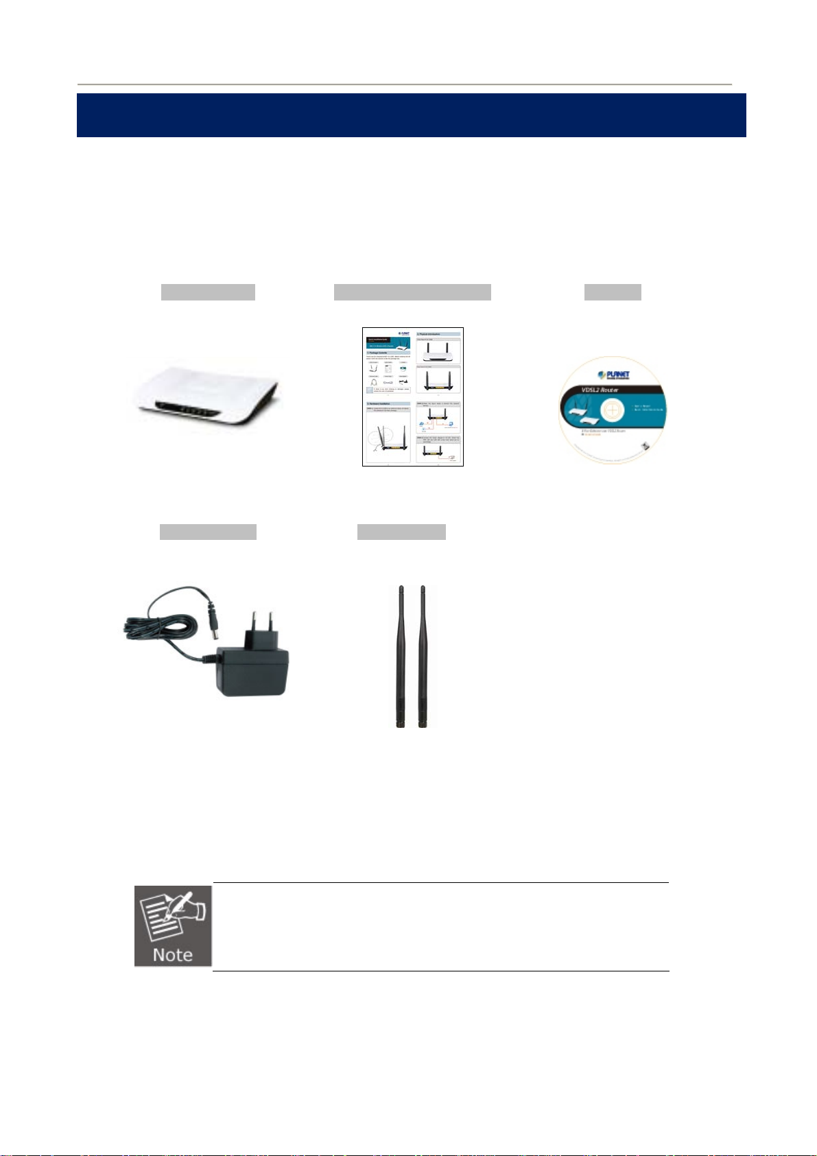
1.1 Package Contents
Thank you for choosing PLANET FRT-405N. Before installing the router, please verify the contents inside the
package box.
FRT-405N Unit Quick Installation Guide CD-ROM
(User Manual included)
Power Adapter 5dBi Antenna x 2
12V/1A DC output
100~240V AC input
If there is any item missing or damaged, please contact the seller
immediately.
8
Page 9

User Manual of FRT-405N
1.2 Product Description
Delivering High-Demand Service Connectivity for ISP / Triple Play Devices
With built-in 100Base-FX fiber interface, the FRT-405N supports different optic types for WAN and the
distance can be up to 15~60 km through the Fiber connection. The FRT-405N is the ideal solution for FTTH
(Fiber-to-the-home) applications. It can handle multiple high-throughput services such as IPTV, on-line
gaming, VoIP, Internet access and keep the bandwidth usage smoothly. The FRT-405N also incorporates a
4-port 10/100Base-TX switching hub, which makes it easily creates or extends your LAN and prevents the
attacks from Internet.
High-Speed 802.11n Wireless
With built-in IEEE 802.11b/g and 802.11n wireless network capability, the FRT-405N allows any computer and
wireless-enabled network device to connect to it without additional cabling. 802.11n wireless capability brings
users the highest speed of wireless experience ever; the data transmission rate can be as high as 30
The radio coverage is also doubled to offer high speed wireless connection even in widely spacious offices or
houses.
0Mbps.
802.11n
300Mbps
6X faster
802.11g
802.11b
Secure Wireless Access Control
To secure wireless communication, the FRT-405N supports most up-to-date encryptions including WEP,
WPA-PSK and WPA2-PSK. Moreover, the FRT-405N supports WPS configuration with PBC/PIN type for
users to easily connect to a secured wireless network.
Providing Superior Function
The FRT-405N provides user-friendly management interface to be managed easily through standard web
browsers. For networking management features, the FRT-405N not only provides basic router functions such
as DHCP server, virtual server, DMZ, QoS, and UPnP, but also provides full firewall functions including
Network Address Translation (NAT), IP/Port/MAC Filtering and Content Filtering. Furthermore, the
FRT-405N serves as an Internet firewall to protect your network from being accessed by unauthorized users.
11Mbps
*Theory Value
54Mbps
9
Page 10

1.3 Product Features
Internet Access Features
Shared Internet Access: All users on the LAN can access the Internet through the
FRT-405N using only one single external IP address. The local (invalid) IP addresses are
hidden from external sources. This process is called NAT (Network Address Translation).
IEEE 802.3u 100Base-FX standard: The FRT-405N provides long distance connection
base on optical fiber transceiver which supports FTTH and IPTV applications.
Multiple WAN Connection: Upon the Internet (WAN port) connection, the FRT-405N
supports Dynamic IP address (IP address is allocated upon connection), fixed IP address,
PPPoE, PPTP and L2TP.
Bridge and Router Application: The FRT-405N supports two application modes: bridging
and routing modes. Currently, the default mode is routing mode. Note: routing mode and
bridging mode cannot be used simultaneously.
Advanced Internet Functions
Virtual Servers: This feature allows Internet users to access Internet servers on your LAN.
The setup is quick and easy.
User Manual of FRT-405N
Firewall: The FRT-405N supports simple firewall with NAT technology.
Universal Plug and Play (UPnP): UPnP allows automatic discovery and configuration of
the Broadband Router. UPnP is supported by Windows ME, XP, or later.
User Friendly Interface: The FRT-405N can be managed and controlled through Web UI.
DMZ Support: The FRT-405N can translate public IP addresses into private IP address to
allow unlimited 2-way communication with the servers or individual users on the Internet. It
provides the most flexibility to run programs smoothly for programs that might be restricted in
NAT environment.
RIP1/2 Routing: It supports RIPv1/2 routing protocol for routing capability.
VPN Pass-through Support: PCs with VPN (Virtual Private Networking) software are
transparently supported - no configuration is required.
LAN Features
4-Port Switch: The FRT-405N incorporates a 4-Port 10/100Base-TX switching hub,
making it easy to create or extend your LAN.
DHCP Server Support: Dynamic Host Configuration Protocol provides a dynamic IP
address to PCs and other devices upon request. The FRT-405N can act as a DHCP Server
for devices on your local LAN.
Wireless Features
Supports IEEE 802.11b, g and 802.11n Wireless Stations: The 802.11n standard
provides backward compatibility with the 802.11b and 802.11g standard, so 802.11b,
802.11g, and 802.11n can be used simultaneously. IEEE 802.11n wireless technology is
capable of up to 300Mbps data rate.
Two External Antennas with MIMO Technology: The FRT-405N provides farther
coverage, less dead spaces and higher throughput with 2T2R MIMO technology.
10
Page 11

User Manual of FRT-405N
WPS Push Button Control: The FRT-405N supports WPS (Wi-Fi Protected Setup) for
users to easily connect to wireless network without configuring the security.
WEP Support: WEP (Wired Equivalent Privacy) is included. Key sizes of 64 bit and 128 bit
are supported.
WPA-PSK Support: WPA-PSK_TKIP and WAP-PSK_AES encryption are supported.
Wireless MAC Access Control: The Wireless Access Control feature can check the MAC
address (hardware address) of wireless stations to ensure that only trusted wireless stations
can access your LAN.
11
Page 12

1.4 Product Specifications
Model FRT-405N
Product Description 300Mbps 802.11n Wireless Internet Fiber Router
Hardware Specifications
LAN 4 x 10/100Base-TX, Auto-Negotiation, Auto MDI/MDI-X RJ45 port
Interface
WAN 1 x 100Base-FX SFP slot
Wireless 2x 5dBi detachable antenna
Connector SFP (Small form-factor Pluggable)
User Manual of FRT-405N
Optic Interface
LED Indicators PWR, WAN, LAN1-4, WLAN, WPS, Security
Button
Material Plastic
Dimensions (W x D x H) 186 x 143 x 35 mm
Power 12V DC, 1A
Router Features
Internet Connection Type Shares data and Internet access for users, supporting the following
Mode
Distance
Vary on module
Vary on module
1 x RESET button
1 x WPS button
internet accesses:
PPPoE
Dynamic IP
Static IP
PPTP
L2TP
Max. Session 15000
50/125μm or 62.5/125μm multi-mode fiber cable, up to 2km.
Fiber-optic cable
Protocol / Feature Router, Bridge and WISP mode
Routing Protocol Static Routing
VPN VPN Pass-through
Security Built-in NAT Firewall
9/125μm single-mode cable, provide long distance for
15/20/35/50km or longer (very on SFP module)
WDS and WPS
DMZ and Virtual Server
802.1D
QoS
DHCP Server / Client
IGMP Proxy and DNS Proxy
UPnP and DDNS
RIPv1/2
MAC / IP/ Port Filtering
Content Filtering
SPI Firewall support
12
Page 13

User Manual of FRT-405N
System Management Web-based (HTTP) configuration
SNTP time synchronize
System Log supports Remote Log
Password protection for system management
Wireless Interface Specifications
Wireless Standard IEEE 802.11b, g and 802.11n
Frequency Band 2.4 to 2.4835GHz (Industrial Scientific Medical Band )
Modulation Type
64-QAM)
802.11n(40MHz):
270/243/216/162/108/81/54/27Mbps
135/121.5/108/81/54/40.5/27/13.5Mbps (Dynamic)
802.11n(20MHz):
DBPSK, DQPSK, QPSK, CCK and OFDM (BPSK/QPSK/16-QAM/
Data Transmission Rates
130/117/104/78/52/39/26/13Mbps
65/58.5/52/39/26/19.5/13/6.5Mbps (Dynamic)
802.11g:
54/48/36/24/18/12/9/6Mbps (Dynamic)
802.11b:
11/5.5/2/1Mbps (Dynamic)
Channel Maximum 14 Channels, depending on regulatory authorities
Antenna Connector 2 x 5dBi detachable Antenna
Wireless Data Encryption
64/128-bit WEP, WPA-PSK, WPA2-PSK, 802.1x encryption, and
WPS PBC
Standards Conformance
Fiber Interface
Complaint with IEEE802.3 / 802.3u 10/100 Base-TX, 100Base-FX
Standard
standard
U0 Band Support (25KHz to 276KHz)
Packet Transfer Mode Ethernet in the First Mile(PTM-EFM)
Environment Specifications
Temperature / Humidity Operating: 0~50 degrees C, 5%~ 90% (non-condensing),
Storage: -20~70 degrees C, 0~95% (non-condensing)
Certification FCC, CE
13
Page 14
User Manual of FRT-405N
Chapter 2. Hardware Installation
This chapter offers information about installing your router. If you are not familiar with the hardware or software
parameters presented here, please consult your service provider for the values needed.
2.1 Hardware Description
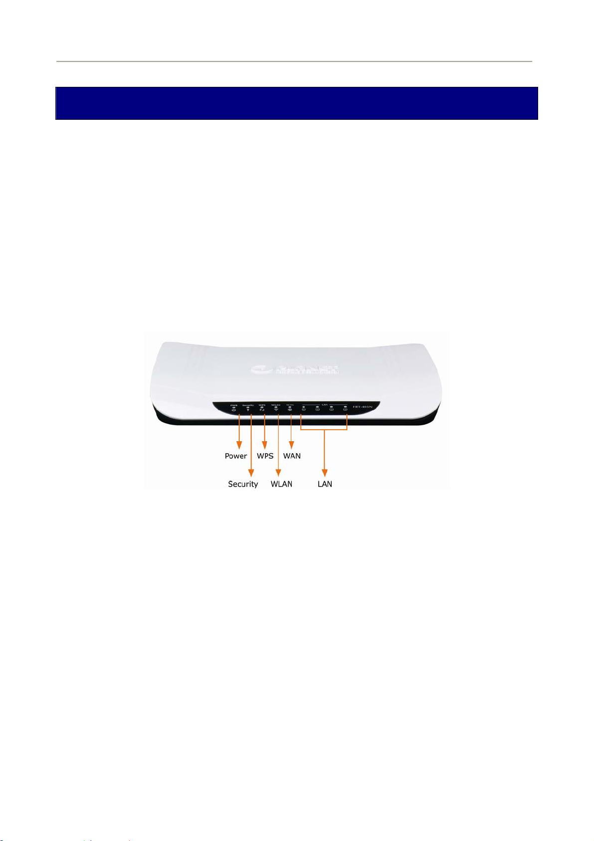
2.1.1 Front Panel of FRT-405N
The front panel provides a simple interface monitoring of the router. Figure 2-1 shows the front panel of the
FRT-405N.
Figure 2-1 FRT-405N Front Panel
2.1.2 LED Indications of FRT-405N
The LEDs on the top panel indicate the instant status of system power, WAN data activity and port links, and
help monitor and troubleshoot when needed. Figure 2-1 and Table 2-1 show the LED indications of the
FRT-405N.
14
Page 15
Front Panel LED Definition
LED State Description
User Manual of FRT-405N
WPS
Security
PWR
WLAN
WAN
LAN1-4
ON When the router is powered on, and in ready state.
OFF When the router is powered off.
ON WPS client registration is successful.
Flashing WPS client registration window is currently open.
OFF WPS is not available, or WPS is not enabled or initialized.
ON WLAN radio is on.
Flashing Data is being transmitted through WLAN.
OFF WLAN radio is off.
ON Enable WLAN encryption
OFF Disable WLAN encryption
Flashing Router is trying to establish a WAN connection to device.
ON The WAN is connected successfully.
Flashing Data is being transmitted or received via the corresponding LAN port.
ON The port is up.
Table 2-1 The LED indication of FRT-405N
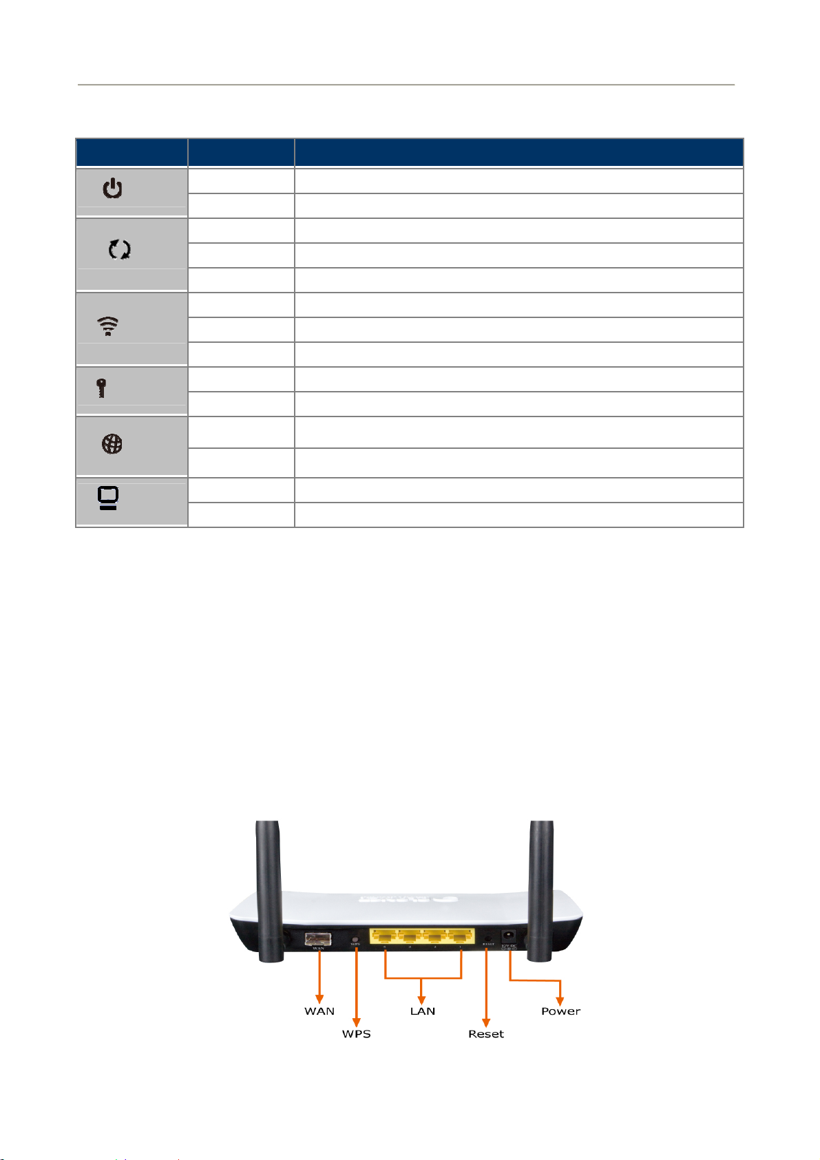
2.1.3 Rear Panel of FRT-405N
The rear panel provides the physical connectors connected to the power adapter and any other network device.
Figure 2-2 shows the rear panel of the FRT-405N.
Figure 2-2 FRT-405N Rear Panel
15
Page 16

Rear Panel Port and Button Definition
Connector Description
POWER Power connector with 12V DC 1 A
RESET Press more than 3 seconds for reset to factory default setting.
Router is successfully connected to a device through the corresponding port (1, 2, 3, or 4). If
LAN (1-4)
WPS WPS on or off switch.
the LED light of LNK/ACT is flashing, the Router is actively sending or receiving data over that
port.
User Manual of FRT-405N
WAN
The SFP connector allows data communication between the router and the fiber network
through a fiber wire
2.2 Cabling
100Base-TX and 100Base-FX
The 10/100Mbps RJ-45 ports come with Auto-Negotiation capability. Users only need to plug in working
network device into one of the 10/100Mbps RJ-45 ports. The FRT-405N will automatically run in 10Mbps
or 100Mbps after the negotiation with the connected device. The FRT-405N has one 100Base-FX SFP
interface (Optional Multi-mode / Single-mode 100Base-FX SFP module)
Cabling
Each 10/100Base-TX ports use RJ-45 sockets - for connection of unshielded twisted-pair cable (UTP).
Port Type Cable Type Connector
10Base-T Cat 3, 4, 5, 2-pair RJ-45
100Base-TX Cat.5, 5e, 6 UTP, 2-pair RJ-45
Any Ethernet devices like Hubs / PCs can connect to the Fiber router by using straight-through wires. The
10/100Mbps RJ-45 ports which support Auto MDI / MDI-X can be used on straight-through or crossover cable.
2.2.1 Installing the SFP Transceiver
This section describes how to insert a SFP transceiver into an SFP slot. The SFP transceiver is hot-pluggable
and hot-swappable. You can plug-in and out the transceiver to/from any SFP port without having to power
down the fiber router as the Figure 2-12 appears.
16
Page 17

User Manual of FRT-405N
Figure 2-3 Plug in the SFP transceiver
Before conn
1. Make sure both sides of the SFP transceiver are with the same media
100Base-FX to 100Base-FX, 100Base-BX20-U to 100Bas
2. Check whether the fiber-optic cable type matches the SFP transceiver model.
To connect to MFB-FX SFP trans
To connect to MFB-F20/F40/F60/FA20/FB20 SFP tra
Connecting the fiber cable
1. Attach the duplex LC connector on the network cable to the SFP transceiver.
2. Connect the other end of the cable
3. Check the LNK/ACT
ecting the other switches, workstation or Media Converter,
type or WDM pair; for example,
e-BX20-D.
ceiver, use the multi-mode fiber cable, with one side being the
male duplex LC connector type.
nsceiver, use the single-mode fiber cable, with
one side being the male duplex LC connector type.
to a device – switches with SFP installed, fiber NIC on a
workstation or a Media Converter.
LED of the SFP slot of the switch / converter. Ensure that the SFP transceiver is
operating correctly.
4. Check the Link mode of the SFP port if the link fails. It function
Converters; setting the Link mode to “100 Force” is needed.
2.2.2 Removing the Module
1. Please make sure there is no network activity by console o
can access the management interface
2. Remove the Fiber Optic Cable gently.
3. Turn the handle of the MFB module / mini GBIC
4. Pull out the module gently through the handle.
of the Fiber router to disable the port in advance.
SFP module to horizontal.
17
s with some fiber-NICs or Media
r check with the network admin
istrator. You
Page 18

User Manual of FRT-405N
Never pull out the module without pulling the lever or the push bolts on the
module. Directly pulling out the module with force could damage the module
and SFP module slot of the device.
18
Page 19
User Manual of FRT-405N
Chapter 3. Connecting to the Router
3.1 System Requirements
Broadband Internet Access Service (FTTH connection)
PCs with a working Ethernet Adapter and an Ethernet cable with RJ-45 connectors
PC of subscribers running Windows 98/ME, NT4.0, 2000/XP, Windows Vista / Win 7, MAC OS 9 or
later, Linux, UNIX or other platform compatible with TCP/IP protocols
The above PC is installed with Web browser
1. The Router in the following instructions is named as PLANET FRT-405N
2. It is recommended to use Internet Explore 7.0 or above to access the Router.
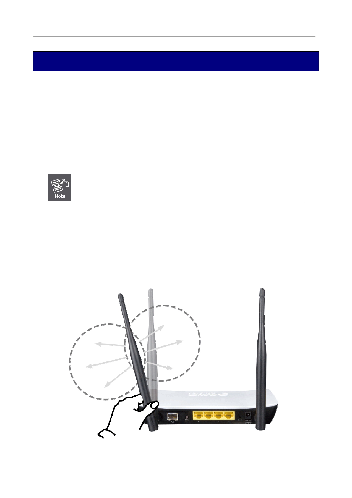
3.2 Installing the Router
Please connect the device to your computer as follows:
Locate the FRT-405N in an optimum place and adjust the antenna for the best coverage. Figure 3-1
shows the antenna connection diagram.
Figure 3-1: FRT-405N Antenna Adjustment Diagram
19
Page 20
User Manual of FRT-405N
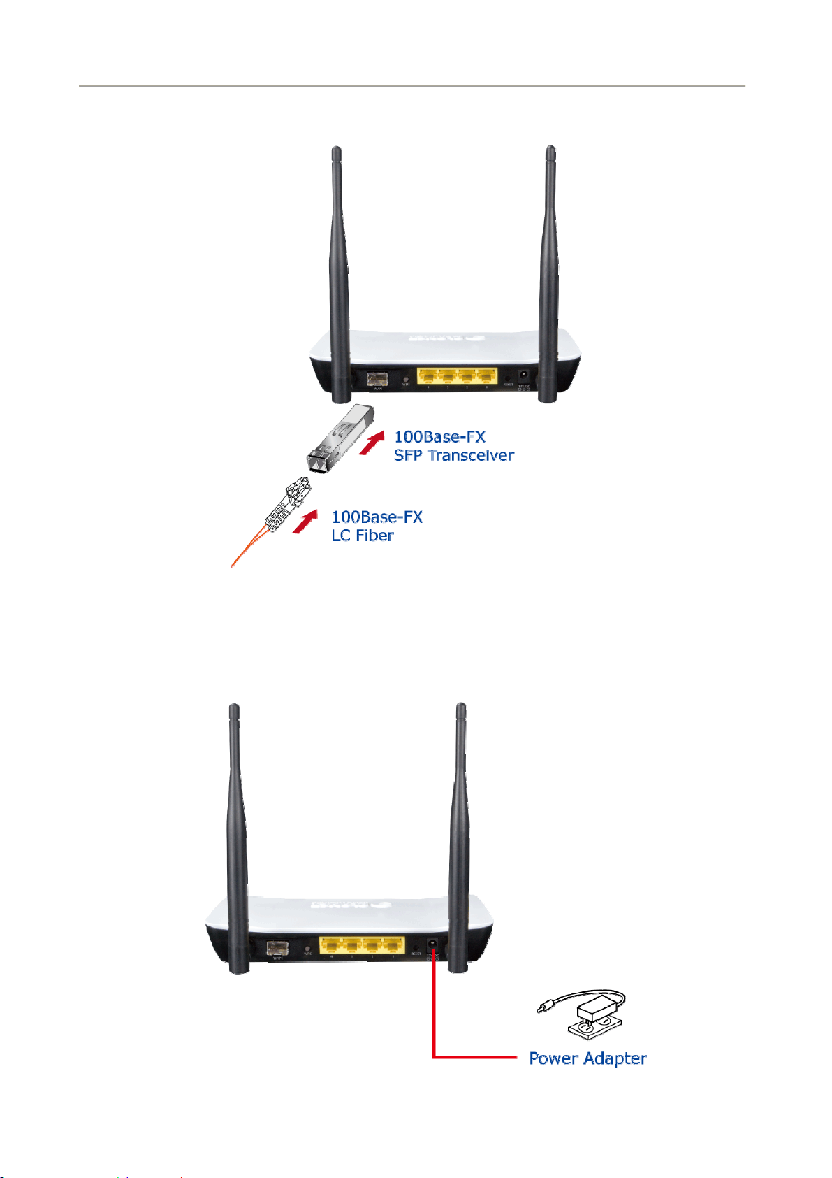
Connect your fiber wire to the “WAN” Port via SFP fiber wire.Figure3-2 shows the WAN port
connection diagram
Figure 3-2: FRT-405N WAN port Connection Diagram
Use Ethernet cable to connect “LAN” port of the modem and “LAN” port of your computer.
Connect Power Adapter to the FRT-405N. Figure3-3 shows the power adapter connection diagram.
Figure 3-3: FRT-405N Power Adapter Connection Diagram
20
Page 21
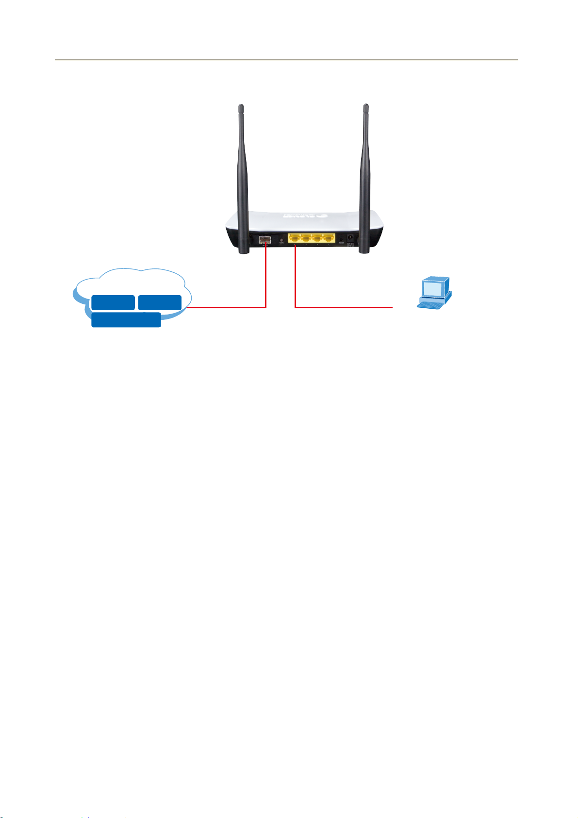
Follow Figure 3-4 to connect the network devices.
User Manual of FRT-405N
Internet
Data IPTV
Entertainment
100Base-FX
Fiber Optical
(DHCP Client or 192.168.1.2)
Figure 3-4: FRT-405N Connection Diagram
PC
21
Page 22
User Manual of FRT-405N
Chapter 4. Installation Guide
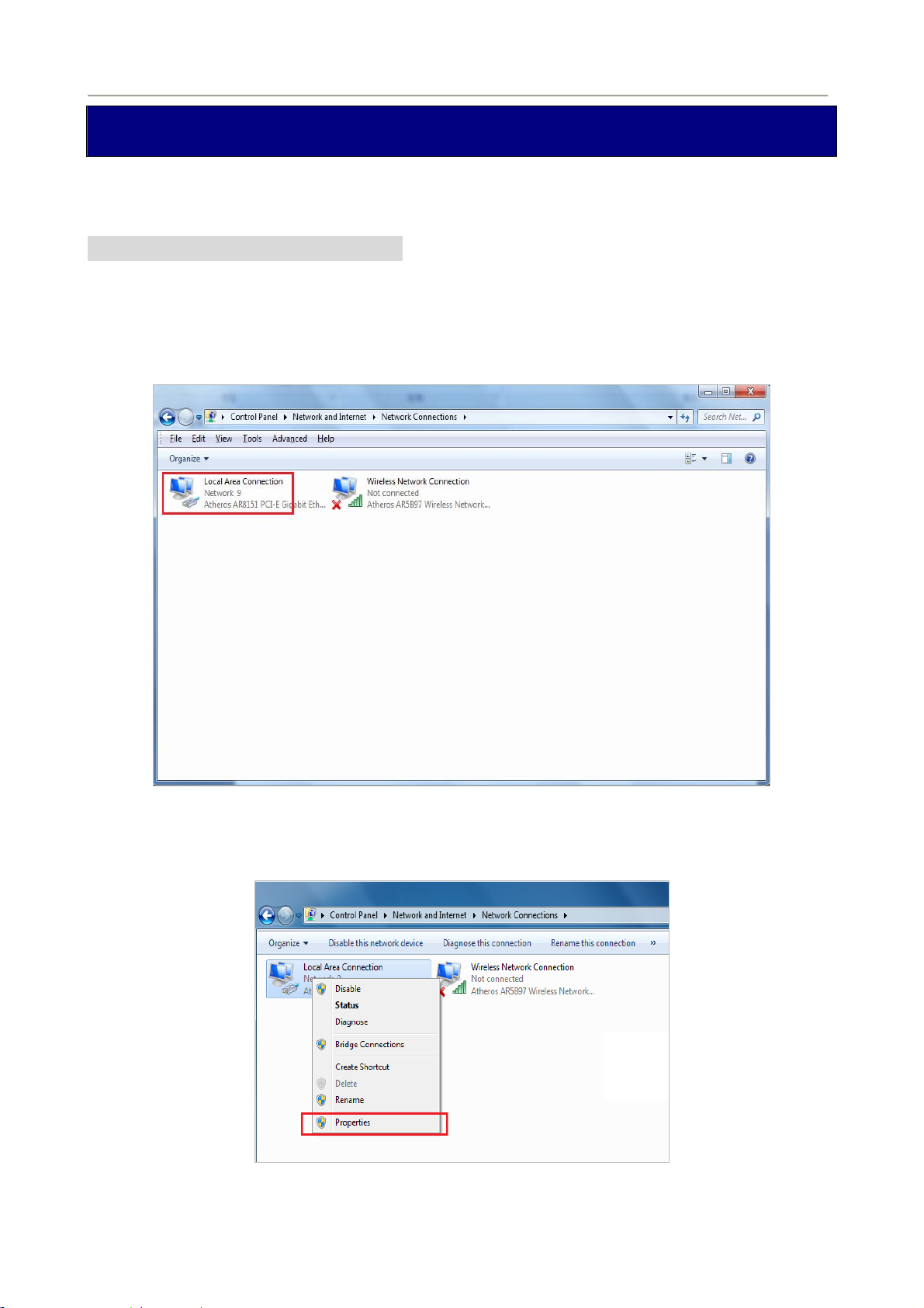
4.1 Configuring the Network Properties
Configuring PC in Windows 7
1. Go to Start / Control Panel / Network and Internet / Network and Sharing Center. Click Change
adapter settings on the left banner.
2. Double-click Local Area Connection.
Figure 4-1-1 Select Local Area Connection
3. In the Local Area Connection Status window, click Properties.
Figure 4-1-2 Network Connection Properties
22
Page 23
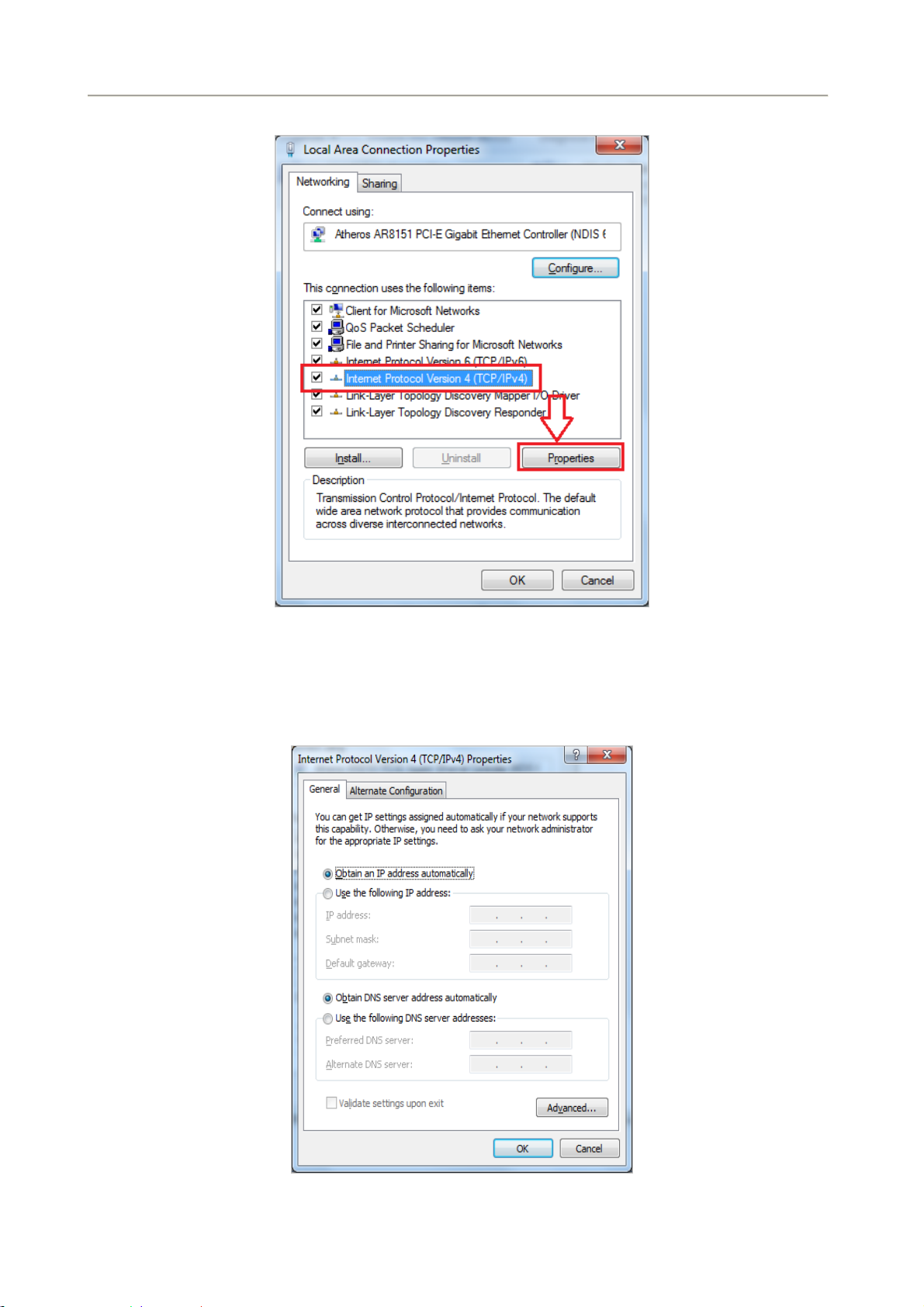
4. Select Internet Protocol Version 4 (TCP/IPv4) and click Properties.
User Manual of FRT-405N
Figure 4-1-3 TCP/IP Setting
5. Select the Obtain an IP address automatically and the Obtain DNS server address automatically
button.
6. Click OK to finish the configuration.
Figure 0-1-4 Obtain an IP address automatically
23
Page 24
User Manual of FRT-405N
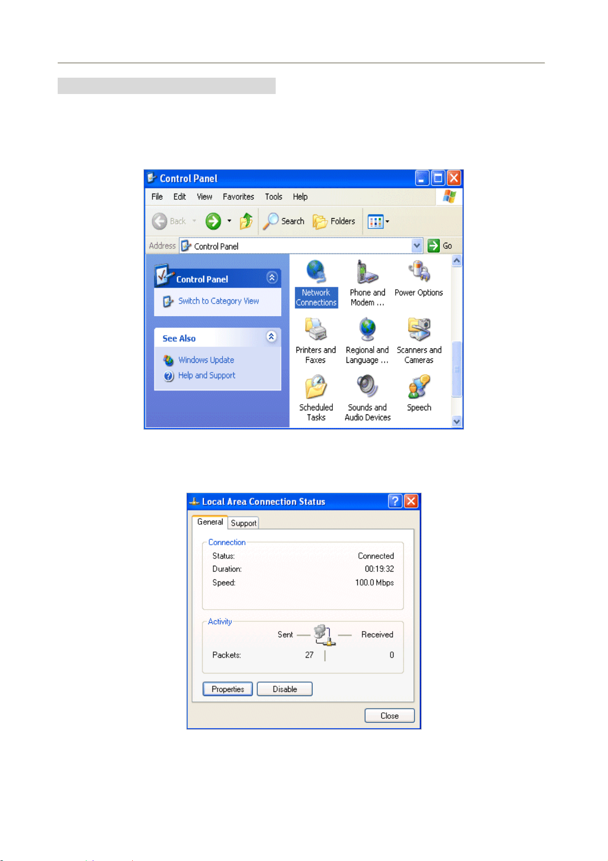
Configuring PC in Windows XP
1. Go to Start / Control Panel (in Classic View). In the Control Panel, double-click on Network
Connections
2. Double-click Local Area Connection.
Figure 4-1-5 Select Network Connections
3. In the Local Area Connection Status window, click Properties.
Figure 4-1-6
24
Page 25
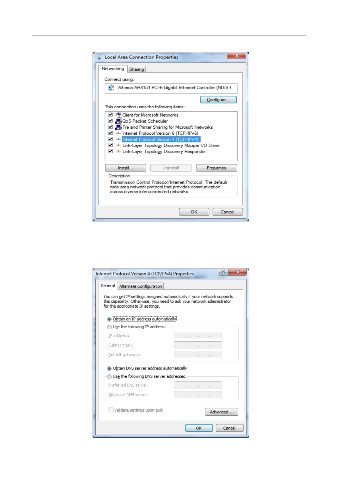
4. Select Internet Protocol (TCP/IP) and click Properties.
User Manual of FRT-405N
Figure 4-1-7 TCP/IP Setting
5. Select the Obtain an IP address automatically and the Obtain DNS server address automatically
button.
6. Click OK to finish the configuration.
Figure 4-1-8 Obtain an IP address automatically
25
Page 26
User Manual of FRT-405N
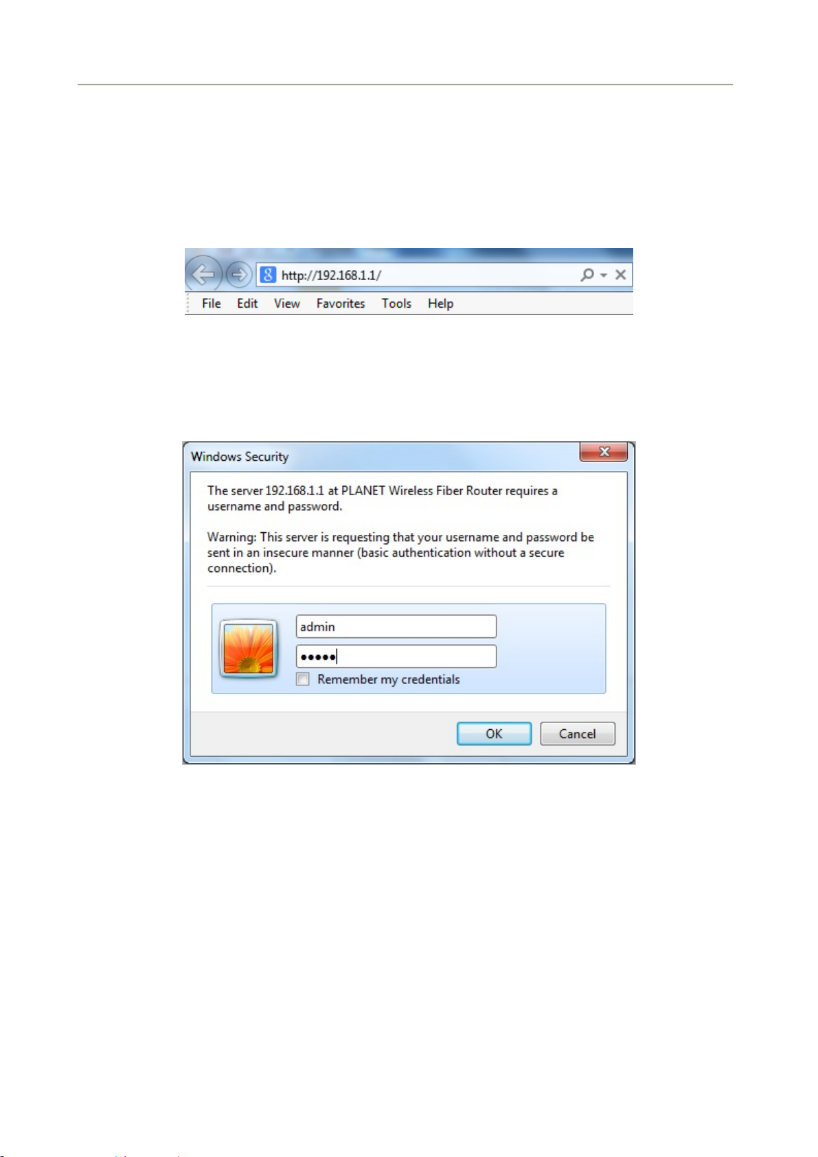
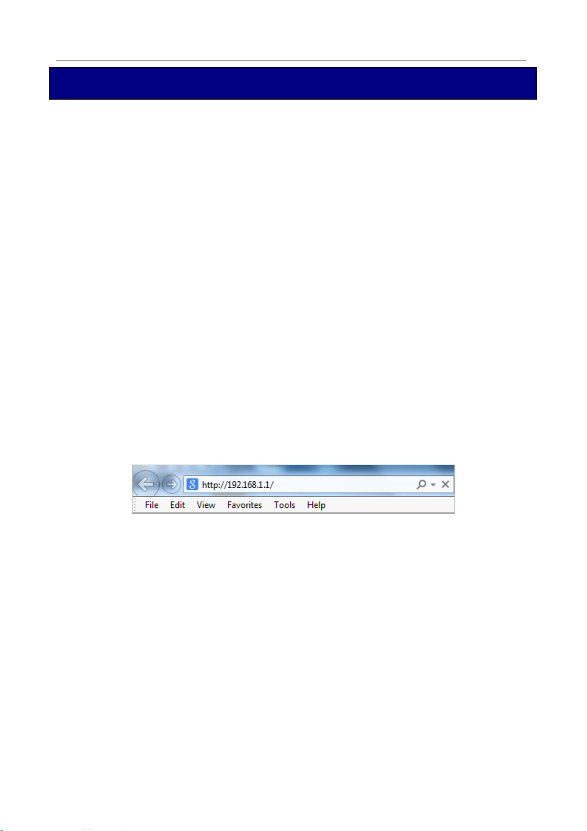
4.2 Configuring with Web Browser
It would be better to change the administrator password to safeguard the security of your network. To
configure the router, open your browser, type “http: //192.168.1.1” into the address bar and click “Go” to get
to the login page.
Save this address in your Favorites for future reference.
Figure 4-2-1 Login the Router
At the User Name and Password prompt, type your proper user name and password to login. The default user
name / password are “admin / admin”. You can change these later if you wish. Click “OK”
.
Figure 4-2-2 Login Window
If the user name and password are correct, you will login Fiber Router successfully and see the status page.
Now you can configure the Fiber Router for your needs.
26
Page 27
User Manual of FRT-405N
Chapter 5. System Settings
Determine your Connection Settings
Before you configure the router, you need to know the connection information supplied by your Internet
service provider.
Connecting the Fiber Router to your Network
Unlike a simple hub or switch, the setup of the Fiber Router consists of more than simply plugging everything
together. Because the Router acts as a DHCP server, you will have to set some values within the Router, and
also configure your networked PCs to accept the IP Addresses the Router chooses to assign them.
Generally there are several different operating modes for your applications. And you can know which mode is
necessary for your system from ISP. These modes are router, bridge, and PPPoE+NAT.
Configuring with Web Browser
It is advisable to change the administrator password to safeguard the security of your network. To configure
the router, open your browser, type “http: //192.168.1.1” into the address bar and click “Go” to get to the
login page.
Save this address in your Favorites for future reference.
Figure 5-1 Login the Router
At the User Name prompt, type “admin”, and the Password prompt, type “admin”. You can change these
later if you wish. Click “OK” to login the router and you can start to configure it now.
27
Page 28
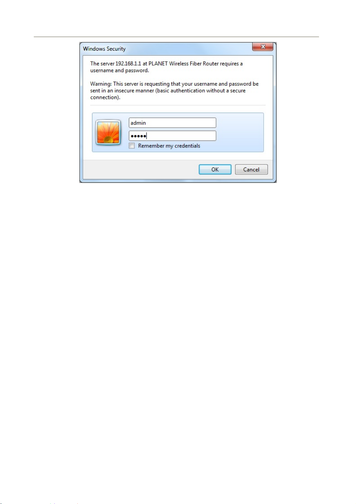
Figure 5-2 Login Window
User Manual of FRT-405N
28
Page 29

User Manual of FRT-405N
5.1 Operation Mode
The FRT-405N supports three operation modes – Bridge, Gateway and WISP. Currently, the default setting is
Gateway mode.
Please note that Bridge mode and Gateway mode cannot be used simultaneously.
For Bridge mode, all interfaces are bridged into a single bridge interface.
For Gateway mode, the fiber port is treated as WAN port. The other interfaces are bridged together and are
treated as LAN ports.
For WISP Mode, all the Ethernet ports (including fiber port) are bridged together and the wireless interface of
this router will come to WAN port for connecting to an ISP’s Access Point as Internet connection. The NAT is
enabled and PCs in Ethernet ports share the same IP to ISP through wireless LAN. The connection type can
be set up on WAN page by using PPPoE, DHCP client, PPTP/L2TP client or static IP.
If you select Bridge mode and WAN configuration in Internet Settings that are not
available, firewall functions on the left page are not available, either.
After finishing the settings, click Apply to save the settings and enable the new configuration to take effect.
Click Cancel to close without saving.
29
Page 30
User Manual of FRT-405N
5.2 Internet Settings
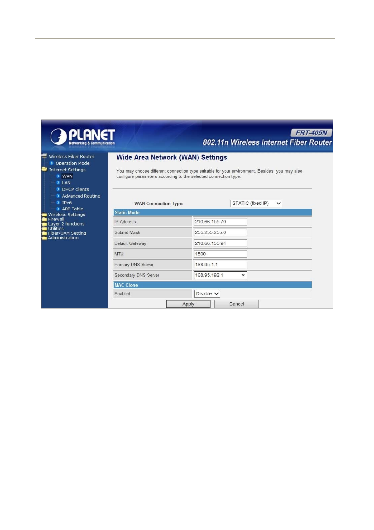
5.2.1 WAN
The WAN Settings screen allows you to specify the type of Internet connection. The WAN settings offer the
following selections for the router’s WAN port, STATIC (fixed IP), DHCP (Auto config), PPPoE, L2TP, and
PPTP.
STATIC (FIXED IP)
Select STATIC (fixed IP) in the WAN Connection Type drop-down list and the following page appears:
30
Page 31

The page includes the following fields:
User Manual of FRT-405N
Object Description
IP Address
Subnet Mask
Default Gateway
Primary/Secondary DNS
MAC Clone
Enter the IP address in dotted-decimal notation provided by your ISP.
Enter the subnet Mask in dotted-decimal notation provided by your ISP,
usually is 255.255.255.0
Enter the gateway IP address in dotted-decimal notation provided by
your ISP.
Enter one or two DNS addresses in dotted-decimal notation provided by
your ISP.
Enable or disable MAC clone.
DHCP (AUTO CONFIG)
Select DHCP (Auto config) in the WAN Connection Type drop-down list and the following page appears.
If the WAN connection type is set to DHCP, the device automatically obtains the IP address, gateway and
DNS address from the DHCP server on WAN interface.
31
Page 32

User Manual of FRT-405N
The page includes the following fields:
Object Description
Host Name
MAC Clone
This option specifies the Host Name of the Router.
Enable or disable MAC clone.
32
Page 33

User Manual of FRT-405N
PPPOE
Select PPPoE (ADSL) in the WAN Connection Type drop-down list and the following page appears. If the
WAN connection type is set to PPPoE, you can configure the following parameters to PPPoE dial up.
The page includes the following fields:
Object Description
User Name/Password
Verify Password
Operation Mode
MAC Clone
Enter the User Name and Password provided by your ISP. These fields
are case-sensitive.
Fill in the password again for verification.
Keep Alive: Keep the PPPoE connection all the time. Please also
On Demand: Please configure the Idle Time field. When time is
Manual: Close all function.
Enable or disable MAC clone.
configure the Redial Period field.
up, the PPPoE connection will disconnect. The connection will
re-connect when any outgoing packet arise.
33
Page 34

User Manual of FRT-405N
L2TP
Select L2TP in the WAN Connection Type drop-down list and the following page appears. There are two
address modes: Static and Dynamic.
1. If you select Static in the Address Mode field, the page shown in the following figure appears:
2. If you select Dynamic in the Address Mode field, the page shown in the following figure appears:
34
Page 35

User Manual of FRT-405N
The page includes the following fields:
Object Description
Allow user to make a tunnel with remote site directly to secure the data
transmission among the connection. User can use embedded L2TP client
Server IP
User Name/Password
MTU
Address Mode
IP Address
supported by this router to make a VPN connection.
If you select the L2TP support on WAN interface, fill in the IP address for
it.
Enter the User Name and Password provided by your ISP. These fields are
case-sensitive.
The Maximum Transmission Unit default setting is 1500.
Static: To configure the IP address information by manually, please
fill in the related setting at below.
Dynamic: The option allows the machine to get IP address
information automatically from DHCP server on WAN side.
Fill in the IP address for WAN interface.
Subnet Mask
Default Gateway
Operation Mode
MAC Clone
Fill in the subnet mask for WAN interface.
Fill in the default gateway for WAN interface out going data packets.
Keep Alive: Keep the L2TP connection all the time. Please also
configure the Redial Period field.
Manual: All functions are disabling.
Enable or disable MAC clone.
35
Page 36

User Manual of FRT-405N
PPTP
Select PPTP in the WAN Connection Type drop-down list and the following page appears. There are two
address modes: Static and Dynamic.
The page includes the following fields:
Object Description
Allow user to make a tunnel with remote site directly to secure the data
transmission among the connection. User can use embedded PPTP
Server IP
User Name/Password
MTU
Address Mode
IP Address
client supported by this router to make a VPN connection.
If you select the PPTP support on WAN interface, fill in the IP address
for it.
Enter the User Name and Password provided by your ISP. These fields
are case-sensitive.
The Maximum Transmission Unit default setting is 1500.
Static: To configure the IP address information by manually, please fill
in the related setting at below.
Dynamic: The option allows the machine to get IP address information
automatically from DHCP server on WAN side.
Fill in the IP address for WAN interface.
36
Page 37

User Manual of FRT-405N
Subnet Mask
Default Gateway
Operation Mode
MAC Clone
Fill in the subnet mask for WAN interface.
Fill in the default gateway for WAN interface out going data packets.
Keep Alive: Keep the PPTP connection all the time. Please also
configure the Redial Period field.
Manual: No function is enabling.
Enable or disable MAC clone.
37
Page 38

User Manual of FRT-405N
5.2.2 LAN
This page allows you to enable or disable networking functions and configure their parameters according to
your practice.
The page includes the following fields:
Object Description
The physical address of the Router, as seen from the LAN. The value
MAC Address
can't be changed.
Enter the IP address of your Router or reset it in dotted-decimal
IP Address
notation (factory default: 192.168.1.1).
An address code that determines the size of the network. Normally use
Subnet Mask
255.255.255.0 as the subnet mask.
MAC Address MAC address of LAN port (Read-only).
Disable: Disable DHCP server on LAN side.
DHCP Type
Server: Enable DHCP server on LAN side.
Start IP Address Fill in the start IP address to allocate a range of IP addresses; client
38
Page 39

User Manual of FRT-405N
with DHCP function set will be assigned an IP address from the range.
End IP Address
Subnet Mask The subnet mask of dynamic IP.
Primary DNS Server The primary DNS server address.
Secondary DNS Server The secondary DNS server address.
Default Gateway Fill in the default gateway for LAN interfaces out going data packets.
Lease Time Fill in the lease time of DHCP server function.
Statically Assigned
802.1d Spanning Tree
LLTD
IGMP Proxy Select enable or disable the IGMP proxy function from pull-down menu.
UPNP Select enable or disable the UPnP protocol from pull-down menu.
Router Advertisement You can select Enable or Disable.
Fill in the end IP address to allocate a range of IP addresses; client with
DHCP function set will be assigned an IP address from the range.
Assign IP to the assigned MAC address. Enter the assigned MAC
address and IP in the corresponding fields.
Select enable or disable the IEEE 802.1d Spanning Tree function from
pull-down menu.
Select enable or disable the Link Layer Topology Discover function
from pull-down menu.
PPPoE Relay You can select Enable or Disable.
DNS Proxy Select enable or disable the DNS Proxy function from pull-down menu.
5.2.3 DHCP clients
You can view the information about DHCP clients on the page.
5.2.4 Advanced Routing
You can add or delete routing rules, and enable or disable dynamic routing protocol on the page.
39
Page 40

User Manual of FRT-405N
The page includes the following fields:
Object Description
Destination
Range
Gateway
Interface
Comment
Enter the legal destination IP address.
Destination IP address is a host address or the network address.
Enter the specific gateway.
The interface for this route. You can select LAN, WAN and Custom.
Add the description of this route.
Current Routing Table in the System
You can delete or reset the routing rules.
Dynamic Routing Settings
You can enable or disable the RIP.
After finishing the settings above, click Apply to enable the new routing rule to take effect. Otherwise, click
Reset to cancel the new routing rule.
40
Page 41

User Manual of FRT-405N
5.2.5 IPv6
You may set up rules to provide Quality of Service (QoS) guarantee for some specific applications. On the
page, you can enable or disable Quality of Service.
The page includes the following fields:
Object Description
Address
Prefix
Router
You can set up IPV6 address here.
You can set up the IPv6 Prefix here.
You can set up the IPv6 router here.
5.2.6 ARP Table
You can view the information about ARP Table on the page.
41
Page 42

User Manual of FRT-405N
5.3 Wireless Setting
5.3.1 Basic
You can configure the minimum number of wireless settings for communication, such as network name (SSID)
and channel.
The page includes the following fields:
Object Description
Driver Version Show the driver version.
WiFi On/Off Enable or disable the wireless LAN.
Network Mode This field determines the wireless mode which the Router works on.
Network Name (SSID) Enter a value of up to 32 characters. The same name of SSID (Service
Set Identification) must be assigned to all wireless devices in your
network. Considering your wireless network security, the default SSID
is set to be default. This value is case-sensitive. For example, PLANET
42
Page 43

User Manual of FRT-405N
is NOT the same as planet.
Multiple SSID 1/2/3/4 There are 4 multiple SSIDs. Enter their descriptive names that you
want to use.
Broadcast Network
Name (SSID)
Select Enable to allow the SSID broadcast on the network, so that the
STA can find it. Otherwise, the STA cannot find it.
AP Isolation Enable or disable AP Isolation. When many clients connect to the
same access point, they can access each other.
If you want to disable the access between clients which connect the
same access point, you can enable this function.
MBSSID AP Isolation Enable or disable MBSSID AP Isolation.
BSSID Basic Service Set Identifier. This is the assigned MAC address of the
station in the access point.
This unique identifier is in Hex format and can only be edited when
Multi BSSID is enabled in the previous screen.
Frequency (Channel)
A channel is the radio frequency used by wireless device. Channels
available depend on your geographical area. You may have a choice
of channels (for your region) and you should use a different channel
from an adjacent AP to reduce the interference. The Interference and
degrading performance occurs when radio signals from different APs
overlap.
HT Physical Mode
43
Page 44

The page includes the following fields:
Object Description
User Manual of FRT-405N
Operation Mode
Channel Bandwidth
Guard Interval
MCS
Reverse Direction
Grant (RDG)
Space Time Block
Coding (STBC)
Aggregation MSDU
(A-MSDU)
Select Mixed Mode or Green Field.
Select 20 or 20/40.
Select 20 or 20/40.
Select the proper value from 0 to 32. Auto is the default value.
The purpose of the 802.11n RD protocol is to more efficiently transfer
data between two 802.11 devices during a TXOP by eliminating the
need for either device to initiate a new data transfer.
Select Disable or Enable.
Space time block coding is a technique used in wireless
communi
number of an
data to improv
cations to transmit multiple copies of a data stream across a
tennas and to exploit the various received versions of the
e the reliability of data-transfer.
Select Disable or Enable.
A-MSDU aggregation, which allows several MAC-level service data
units (MSDUs) to be aggregated into a single MPDU.
Select Disable or Enable.
Auto Block ACK
Decline BA Request
HT Disallow TKIP
HT TxStream
HT RxStream
Not to respond to each sent data (ACK), but to block unit (Block).
Select Disable or Enable.
To decline the Block ACK request by the other devices.
Select Disable or Enable.
Using TKIP, the operation will be in 802.11g.
Select Disable or Enable.
Select 1 or 2.
Select 1 or 2.
44
Page 45

User Manual of FRT-405N
5.3.2 Advanced
This page includes more detailed settings for the AP. Advanced Wireless Settings page includes items that
are not available on the Basic Wireless Settings page, such as basic data rates, beacon interval, and data
beacon rate.
The page includes the following fields:
Object Description
BG Protection Mode
Beacon Interval
Date Beacon Rate
(DTM)
Fragment Threshold
RTS Threshold
It provides 3 options, including Auto, On, and Off. The default BG
protection mode is Auto.
The interval time range is between 20ms and 999ms for each beacon
transmission. The default value is 100ms.
The DTM range is between 1 ms and 255 ms. The default value is
1ms.
This is the maximum data fragment size (between 256 bytes and 2346
bytes) that can be sent in the wireless network before the router
fragments the packet into smaller data frames. The default value is
2346.
Request to send (RTS) is designed to prevent collisions due to hidden
node. A RTS defines the biggest size data frame you can send before
a RTS handshake invoked. The RTS threshold value is between 1 and
45
Page 46

2347. The default value is 2347.
User Manual of FRT-405N
Tx Power
Short Preamble
Short Slot
Tx Burst
Pkt_Aggregate
Country Code
The Tx Power range is between 1 and 100. The default value is 100.
Short preambles work with every wireless type other than older types
with limited transmission rates in the 1 to 2 Mbps range.
Select Disable or Enable.
Short slot time reduces the slot time from 20 microseconds to 9
microseconds, thereby increasing throughput.
Select Disable or Enable.
TX burst is a feature for wireless device speed up the connection in the
same environment as it is without.
Select Disable or Enable.
Select Disable or Enable.
Select the region which area you are. It provides three regions in the
drop-down list.
Object Description
WMM Capable
APSD Capable
DLS Capable
WiFi Multimedia (WMM) refers to Qos over WiFi. It is suitable for simple
applications that require QoS, such as Voice over IP (VoIP)
r
Enable o
disable WMM.
Automatic power save delivery (APSD) is an efficient power
management method.
Enable or disable APSD.
Direct-Link Setup (DLS) are able to automatically create a secure,
direct link between them after accessing the Wi-Fi network, removing
the need to transmit data through the access point.
Enable or disable DLS.
46
Page 47

Object Description
Multicast-to-Unicast
User Manual of FRT-405N
There are two main ways that Windows Media servers send data to
Windows Media Player clients: multicast and unicast.
Enable or Disable Multicast-to-Unicast
47
Page 48

User Manual of FRT-405N
5.3.3 Security
Choose Wireless Settings>Security and the following page appears. It allows you to modify the settings to
prevent the unauthorized accesses.
The page includes the following fields:
Object Description
SSID choice
Security Mode
Select SSID in the drop-down list.
There are 5 options, including Disable, OPENWEP, WPA-PSK,
WPA2-PSK, and WPAPSKWPA2PSK.
[EXAMPLE]
Take WPAPSKWPA2PSK for example. Select WPAPSKWPA2PSK in the Security Mode down-list. The
page shown in the following page appears:
48
Page 49

User Manual of FRT-405N
Access Policy
Object Description
Policy
Add a station MAC
There are three options, including Disable, Allow, and Reject. Select
Allow, only the clients whose MAC address is listed can access the
router. Select Reject, the clients whose MAC address is listed are
denied to access the router.
If you want to add a station MAC, enter the MAC address of the
wireless station that are allowed or denied access to your router in this
address field.
49
Page 50

User Manual of FRT-405N
5.3.4 WDS
WDS (Wireless Distribution System) allows access points to communicate with one another wirelessly in a
standardized way. It can also simplify the network infrastructure by reducing the amount of cabling required.
Basically the access points will act as a client and an access point at the same time.
WDS is incompatible with WPA. Both features cannot be used at the same time. A WDS link is bi-directional,
so the AP must know the MAC address of the other AP, and the other AP must have a WDS link back to the
AP.
Dynamically assigned and rotated encryption key are not supported in a WDS connection. This means that
WPA and other dynamic key assignment technologies may not be used. Only Static WEP keys may be used
in a WDS connection, including any STAs that are associated with a WDS repeating AP.
Enter the MAC address of the other APs that you want to link to and click enable. Supports up to 4 point to
multipoint WDS links, check Enable WDS and then enable on the MAC addresses.
WDS Mode: There are four options, including Disable, Lazy Mode, Bridge Mode, and Repeater Mode.
Disable
Select Disable to disable the WDS mode.
Lazy Mode
50
Page 51

The page includes the following fields:
Object Description
User Manual of FRT-405N
Lazy Mode
Phy Mode
Encryp Type
The FRT-405N WDS Lazy mode is allowed the other FRT-405N WDS
bridge / repeater mode link automatically.
It provides 4 options, including CCK, OFDM, HTMIX, and
GREENFIELD.
It provides 4 options, including None, WEP, TKIP, and AES.
Bridge Mode/ Repeater Mode
WDS Mode
Phy Mode
Encryp Type
AP MAC Address
Object Description
Select Bridge Mode or Repeater Mode.
It provides 4 options, including CCK, OFDM, HTMIX, and
GREENFIELD.
It provides 4 options, including None, WEP, TKIP, and AES.
It provides 4 AP MAC Address. Enter the MAC address of the other
APs.
51
Page 52

User Manual of FRT-405N
5.3.5 WPS
You can enable or disable the WPS function on this page.
Select Enable in the WPS drop-down list. Click Apply and the following page appear.
52
Page 53

User Manual of FRT-405N
WPS Summary
It displays the WPS information, such as WPS Current Status, WPS Configured, and WPS SSID.
Object Description
Reset OOB
Reset to out of box (OoB) configuration
WPS Progress
There are two ways for you to enable WPS function: PIN or PBC. You can use a push button configuration
(PBC) on the Wi-Fi router. If there is no button, enter 4 digit PIN code. Each STA supporting WPS comes with
a hard-coded PIN code.
Object Description
PIN If you select PIN mode, you need to enter the PIN number in the field.
WPS Status
It displays the information about WPS status.
53
Page 54

User Manual of FRT-405N
5.3.6 Station List
Through this page, you can easily identify the connected wireless stations. It automatically observes the ID of
connected wireless station (if specified), MAC address, and current status.
5.3.7 Statistics
This page will show you the connected TX, RX statistics.
54
Page 55

User Manual of FRT-405N
5.4 Firewall
The VDSL Router provides the fully firewall functions, such as MAC/IP/Port Filtering, Port Forwarding, DMZ,
SPI Firewall and Content Filtering. It serves as an Internet firewall to protect your network from being accessed
by outside users.
5.4.1 MAC/IP/Port Filtering
Use the MAC/IP/Port filters to deny / allow particular LAN IP addresses from accessing the Internet. You can
deny / allow specific port numbers or all ports for a specific IP address.
You may set up firewall rules to protect your network from malicious activity on the Internet. It is also
convenient for you to delete these settings.
55
Page 56

Basic Settings
Object Description
User Manual of FRT-405N
MAC/IP/Port Filtering
Default Policy
Enable or disable the MAC/IP/Port filtering function.
The Packet that does not match any rules would be dropped or
accepted.
MAC/IP/Port Filter Settings
Object Description
Source MAC address
Dest IP Address
Source IP Address
Protocol
Destination Port Range
Enter the MAC address that matches the source address of the packet
(optional).
Enter the IP address that matches the destination address of the
packet (optional).
Enter the IP address that matches the source address of the packet
(optional).
There are 4 options, including none, TCP, UDP and ICMP.
After setting a valid protocol, you may enter the UPD or TCP
destination port range.
Source Port Range
Action
Comment
After setting a valid protocol, you may enter the UPD or TCP source
port range.
Select Drop or Accept in the drop down list.
Add description for this rule.
The maximum rule number you can add is 32.
Current MAC/IP/Port Filtering Rules in System
If you want to delete some rules in the table above, select the rules, and then click Delete Selected. Otherwise,
click Reset.
56
Page 57

User Manual of FRT-405N
5.4.2 Port Forwarding (Virtual Server)
This page allows you to configure to re-direct a particular range of service port numbers from the Internet
network to a particular LAN IP address, and set virtual server to provide services on the Internet.
Port Forwarding Settings
Object Description
Virtual Server Settings
IP Address
Port Range:
Protocol
Comment
The maximum rule number you can add is 32.
Enable or disable this function. After selecting Enable, you can set the
following parameters.
Enter the virtual server IP address in internal network.
You can setup your port range for your WAN side.
There are 3 options, including none, TCP&UDP, TCP and UDP.
Add description for this rule.
57
Page 58

User Manual of FRT-405N
Virtual Server Settings
Object Description
Virtual Server Settings
IP Address
Public Port
Private Port
Protocol
Comment
Enable or disable this function. After selecting Enable, you can set the
following parameters.
Enter the virtual server IP address in internal network.
Enter the WAN service port.
Enter the LAN service port.
There are 3 options, including none, TCP&UDP, TCP and UDP.
Add description for this rule.
The maximum rule number you can add is 32.
58
Page 59

User Manual of FRT-405N
5.4.3 DMZ
DMZ (De-militarized Zone) allows a single computer on your LAN to expose ALL of its ports to the Internet.
Enter the IP address of that computer as a DMZ (De-militarized Zone) host with unrestricted Internet access.
When doing this, the DMZ host is no longer behind the firewall.
This page allows you to set a De-militarized Zone (DMZ) to separate internal network and Internet.
DMZ Settings: Enable or disable this function. After selecting Enable, you can set the DMZ IP address.
DMZ IP Address: Enter the DMZ host IP address.
59
Page 60

User Manual of FRT-405N
5.4.4 System Security Settings
Choose Firewall > System Security and the following page appears. This page allows you to configure the
system firewall to protect Router from attacking.
Remote Management
Object Description
Remote management
(via WAN)
Remote Web
management Port
Ping from WAN Filter
Object Description
Ping from WAN Filter
Deny or allow remote management through web.
The default remote management port is 80. You can change the
remote management port for your needs. e.g. 8080.
You may select enable or disable to determine whether to filter the
ping package which comes from the external network.
60
Page 61

Block Port Scan
Object Description
User Manual of FRT-405N
Block Port Scan
You may select enable or disable to determine whether to block the
scanning which comes from the external network.
Block SYN Flood
Object Description
Block SYN Flood
You may select enable or disable to determine whether to block the
SYN Flood attacks come from the external network.
Stateful Packet Inspection (SPI)
Object Description
SPI Firewall
You may disable or enable the SPI firewall.
5.4.5 Content Filtering
This page is used to configure the Blocked FQDN (Such as tw.yahoo.com) and filtered keyword. Here you can
add / delete FQDN and filtered keyword.
Choose Firewall > Content Filtering and the following page appears. You can set content filter to restrict the
improper content access.
61
Page 62

Webs Content Filters
Object Description
User Manual of FRT-405N
Webs Content Filters
Current Webs URL Filters
Object Description
Current Webs URL
Filters
Add a URL filter
Object Description
Add a URL filter
If you want to block some applications as Proxy, Java and ActiveX of
web pages please select the check box and click “Apply”.
If you want to delete some filters in the table above, select the rules,
and then click Delete. Otherwise, click Reset.
Enter the FQDN and click “Add” to apply this URL filter rule.
Click Add to add a URL filter. Otherwise, click Reset to cancel the
URL filter.
62
Page 63

User Manual of FRT-405N
5.5 Layer 2 functions
A single layer-2 network may be partitioned to create multiple distinct broadcast domains. Such a domain is
referred to as a Virtual LAN or VLAN. Network administrators set up VLANs to provide the segmentation
services traditionally provided by routers in LAN configuration. This page allows you to set the VLAN.
5.5.1 Port Status
Choose Layer 2 Function > Port Status and the following page appears. This page displays each port’s
Speed, Duplex mode, Flow Control status.
5.5.2 Port Setting
This page allows you to select a different Mode, Flow Control or Port Enable.
63
Page 64

The page includes the following fields:
Object Description
User Manual of FRT-405N
Port
Mode
Flow Control
Port Enable
This is the LAN port number for this row.
You can choose 5 modes.
Auto Negotiation
100 Full
100 Half
10 Full
10 Half
Please select the check box and click “Apply”.
You can choose Enable or Disable.
You can choose Enable or Disable.
5.5.3 VLAN Setting
You can enable or disable the VLAN setting. There are four groups that can be set. The first one is NAT group
and the others are bridged with WAN port.
64
Page 65

User Manual of FRT-405N
VLAN Mode Setting
Mode: You can enable or disable the VLAN here.
VLAN Member Configuration
Object Description
VLAN Group:
VID:
LAN1~4:
PVID:
Click Apply to enable the configuration to take effect. Click Cancel to cancel the new configuration.
You can select enable or disable.
Set the VID here for each Virtual LAN.
It means the LAN port on the router.
You can set the PVID for each port here.
5.5.4 MAC Address Table
This page shows MAC Address Table.
Click Refresh button to renew the list above immediately.
65
Page 66

User Manual of FRT-405N
5.6 Utilities
The FRT-405N provides four functions for users to use.
5.6.1 Ping Test Setup
This page is used to configure the parameters for Ping Test which pings to IP address or Domain Name.
5.6.2 IPv6 Ping Test
This page is used to configure the parameters for IPv6 Ping Test which pings to IPv6 address or Domain
Name.
66
Page 67

User Manual of FRT-405N
5.6.3 Trace Route
This page is used to configure the Traceroute which traces to IP address or Domain Name.
67
Page 68

User Manual of FRT-405N
5.6.4 Watch Dog Ping
On this page you can enable Ping Watchdog. And configure the parameters for Ping Watchdog which pings to
IP address every time interval. System will reboot when failing to ping the IP address 3 times.
The page includes the following fields:
Object Description
Ping Count
Time Interval
Set times from 1 to 100.
Set minutes from 1 to 15.
68
Page 69

User Manual of FRT-405N
5.7 Fiber/OAM Setting
You can configure fiber setting in this part. It includes Flow Control, Ingress Rate Limit, Egress Rate Limit.
5.7.1 Fiber Configuration
Choose Fiber/OAM Setting > Fiber Configuration, and the following page appears. This function allows
displaying the Fiber port status, Mode, Flow Control and Rate limit. The Link Status in the screen displays the
current connection speed and duplex mode.
Fiber Configuration
Object Description
Link
Mode
Flow Control
Ingress Rate Limit
Egress Rate Limit
Display the Link situation.
Display the network speed.
Enable or Disable Flow Control function.
Enable: 802.3x flow control is enabled on Full-Duplex mode or
Half-Duplex mode
Disable: No flow control function.
The value of inbound traffic limitation.
Set the Ingress Rate Limit to No Limit, 512K, 1M, 2M, 4M, 8M, 10M,
50M
The value of outbound traffic limitation.
Set the Egress Rate Limit to No Limit, 512K, 1M, 2M, 4M, 8M, 10M,
50M
69
Page 70

User Manual of FRT-405N
5.8 Administration
You can configure admin management in this part. It includes Management, Update Firmware, Setting
Management, Reboot, Status, Statistics and System Log.
5.8.1 Management
Choose Administration > Management, and the following page appears. You may configure administrator
account and password on the page.
Administrator Settings
Object Description
Account
Password
Enter the user name of the administrator in the field.
Enter the user name of the administrator in the field.
5.8.2 Uploading Firmware
Choose Administration > Upload Firmware and the following page appears. On this page, you may
upgrade the correct new version firmware to obtain new functionality. It takes about 2 minutes to upload and
upgrade the flash.
If the firmware is uploaded in an improper way, the system would core dump.
70
Page 71

Updating Firmware
Object Description
User Manual of FRT-405N
Location
Click Browse to select the firmware file, and click Apply to upgrade
the firmware.
5.8.3 Setting Management
Choose Administration > Settings Management and the following page appears. You may save system
settings by exporting them to a configuration file, restore them by importing the file, or reset them to the
factory default.
71
Page 72

Exporting Settings
Object Description
User Manual of FRT-405N
Export Button
Click the Export to export the settings
Importing Settings
Object Description
Import Settings
Import
Click Browse to select the configuration file, and then click
Upload the configuration file. Click Cancel to cancel the uploading
operation.
Loading Factory Defaults
Object Description
Load Default
Click Load Default to make Router return to the default settings.
5.8.4 SNMP Configuration
Simple Network Management Protocol (SNMP) is a popular protocol for network management. It is widely
used in local area networks (LAN) for collecting information, and managing and monitoring, network devices,
such as servers, printers, hubs, switches, and routers from a management host.
Managed devices that support SNMP including software are referred to as an SNMP agent, which usually
interacts with third-party SNMP management software to enable the sharing of network status information
between monitored devices and applications and the SNMP management system.
A defined collection of variables (managed objects) are maintained by the SNMP agent and used to manage
the device. These objects are defined in a Management Information Base (MIB), which provides a standard
presentation of the information controlled by the on-board SNMP agent. SNMP defines both the format of the
MIB specifications and the protocol used to access this information over the network.
Choose Administration > SNMP configuration and the following page appears. You may enable SNMP
Configuration and Trap Configuration settings.
72
Page 73

User Manual of FRT-405N
The page includes the following fields:
SNMP Configuration
Object Description
Indicates the SNMP mode operation. Possible modes are:
Mode
System Description
System Contact:
System Name:
System Location:
Enabled: Enable SNMP mode operation.
Disabled: Disable SNMP mode operation.
Describe the model of the device.
Set the name to access the router. Usually set the administrator’s
name.
Set the router’s name, such as “FRT-405N”.
Set the router’s network location.
Allowed IP to access
Read Community:
Show you the IP that allowed to access.
Indicates the community read access string to permit reading this
router’s SNMP information.
73
Page 74

Write Community:
Trap Configuration
Object Description
User Manual of FRT-405N
The default is Public.
Indicates the community write access string to permit reading and
re-writing this router’s SNMP information.
The default is Private.
Mode :
Trap Community:
Trap Destination :
Click Apply to enable the configuration to take effect. Click Reset button to reset the whole configuration to
default.
Indicates the SNMP trap mode operation. Possible modes are:
Enabled: Enable SNMP trap mode operation.
Disabled: Disable SNMP trap mode operation.
Enter the community string for the trap station.
Enter the IP address of the trap manager.
5.8.5 Reboot
The Reboot screen allows you to restart your router with its current settings. Click the “Reboot” button and the
device will restart.
5.8.6 Status
Choose Administration > Status and the following page appears. It displays the information about Router
status, including system information, Internet configurations, and local network.
74
Page 75

User Manual of FRT-405N
75
Page 76

User Manual of FRT-405N
5.8.7 Statistics
You can see the Statistic information on this screen. It includes the Traffic for all interfaces.
76
Page 77

User Manual of FRT-405N
5.8.8 System Log
The system log dialog allows you to view the system log and click the “Refresh” button to refresh the system
event logs. Choose Administration > System Log and the following page appears. You are allowed to view
and disable / enable the system log on this page.
Click Refresh to refresh the log. Click Clear to clear the log.
5.8.9 TR-069 Client
Choose Administration > TR-069 Client and the following page appears. You are allowed to disable or
enable the function on this page.
77
Page 78

User Manual of FRT-405N
5.8.10 NTP
Choose Administration > NTP and the following page appears. You may configure NTP settings on this
page.
NTP Settings
Object Description
Current Time
Time Zone
NTP Server
NTP synchronization
Display the current date and time. Click Sync with host, the current
time is synchronized by your PC which is connected to Router.
Select the proper time zone in the drop-down list.
Enter the IP address or domain name of NTP server.
Enter the time interval for synchronization. From 1 to 300 minutes.
78
Page 79

User Manual of FRT-405N
5.8.11 DDNS
The Wireless Router offers the DDNS (Dynamic Domain Name System) feature, which allows the hosting of a
website, FTP server, or e-mail server with a fixed domain name (named by yourself) and a dynamic IP address,
and then your friends can connect to your server by entering your domain name no matter what your IP
address is. Before using this feature, you need to sign up for DDNS service providers such as PLANET DDNS
or dynamic DNS
Choose Administration > DDNS and the following page appears. You can choose Disable, Enable Easy
DDNS and Dynamic DDNS settings on this page.
. The Dynamic DNS client service provider will give you a password or key.
Easy DDNS
Planet Easy DDNS is a way help to get your Domain Name with just one click. Once you enabled the Easy
DDNS, your Planet Network Device will use the format PLxxxxxx where xxxxxx is the last 6 characters of your
MAC address that can be found on the web page or bottom label of the device. (For example,
00-30-4F-12-34-07, it will be converted into PL123407.planetddns.com)
79
Page 80

User Manual of FRT-405N
DDNS Settings
Object Description
Select the proper dynamic DNS provider in the drop-down list. After
Dynamic DNS Provider
Account
Password
DDNS
selecting a dynamic DNS provider, you are allowed to set the following
parameters.
Enter the username of DDNS provider in the field.
Enter the password of DDNS provider in the field.
Enter the domain name of your device.
Planet DDNS
First of all, please go to http://www.planetddns.com to register a Planet DDNS account, and refer to the FAQ
(http://www.planetddns.com/index.php/faq
) for how to register a free account.
80
Page 81

To select Dynamic DNS Provider > PlanetDDNS.com
User Manual of FRT-405N
Step 1. Type the User Name for your DDNS account.
Step 2. Type the Password for your DDNS account.
Step 3. Type the Domain Name you received from dynamic DNS service provider.
Go to Firewall >System Security> Remote management and choose Allow to allow remote access from
WAN port.
81
Page 82

User Manual of FRT-405N
Apply the settings and ensure you have connected the WAN port to the Internet. In a remote device, enter the
Domain Name to the internet browser’s address bar.
You can go to My Devices page of Planet DDNS website to check if the “Last Connection IP” is displayed. This
indicates your DDNS service is working properly.
82
Page 83

User Manual of FRT-405N
5.8.12 Max Session
Choose Administration > Max Session and the following page appears. You may configure Max Session on
this page.
5.8.13 Session List
Choose Administration > Session List and the following page appears. You may monitor Session List on
this page.
83
Page 84

User Manual of FRT-405N
Chapter 6. Quick Connection to a Wireless Network
In the following sections, the default SSID of the FRT-405N is configured to “default”.
6.1 Windows XP (Wireless Zero Configuration)
Step 1: Right-Click on the wireless network icon displayed in the system tray
Figure 6-1 System Tray – Wireless Network Icon
Step 2: Select [View Available Wireless Networks]
Step 3: Highlight and select the wireless network (SSID) to connect
(1) Select SSID [default]
(2) Click the [Connect] button
Figure 6-2 Choose a wireless network
84
Page 85

Step 4: Enter the encryption key of the Wireless AP
(1) The Wireless Network Connection box will appear
(2) Enter the encryption key that configured in section 5.3.3
(3) Click the [Connect] button
User Manual of FRT-405N
Figure 6-3 Enter the network key
Step 5: Check if “Connected” is displayed
Figure 6-4 Choose a wireless network -- Connected
85
Page 86

User Manual of FRT-405N
Some laptops are equipped with a “Wireless ON/OFF” switch for the internal wireless LAN. Make
sure the hardware wireless switch is switch to “ON” position.
6.2 Windows 7 (WLAN AutoConfig)
WLAN AutoConfig service is built-in in Windows 7 that can be used to detect and connect to wireless network.
This built-in wireless network connection tool is similar to wireless zero configuration tool in Windows XP.
Step 1: Right-Click on the network icon displayed in the system tray
Figure 6-5 Network icon
Step 2: Highlight and select the wireless network (SSID) to connect
(1) Select SSID [default]
(2) Click the [Connect] button
Figure 6-6 WLAN AutoConfig
86
Page 87

If you will be connecting to this Wireless AP in the future, check [Connect automatically].
Step 4: Enter the encryption key of the Wireless AP
(1) The Connect to a Network box will appear
(2) Enter the encryption key that configured in section 5.3.3
(3) Click the [OK] button
User Manual of FRT-405N
Figure 6-7 Type the network key
Figure 6-8 Connecting to a Network
Step 5: Check if “Connected” is displayed
87
Page 88

User Manual of FRT-405N
Figure 6-9 Connected to a Network
88
Page 89

User Manual of FRT-405N
6.3 Mac OS X 10.x
In the following sections, the default SSID of the FRT-405N is configured to “default”.
Step 1: Right-Click on the network icon displayed in the system tray
The AirPort Network Connection menu will appear
Figure 6-10 Mac OS – Ne
Step 2: Highlight and select the wireless network (SSID) to connect
(1) Select and SSID [default]
(2) Double-click on the selected SSID
twork icon
Figure 6-11 Highlight and select the wireless network
Step 4: Enter the encryption key of the Wireless AP
(1) Enter the encryption key that configured in section 5.3.3
(2) Click the [OK] button
89
Page 90

User Manual of FRT-405N
Figure 6-12 Enter the Password
If you will be connecting to this Wireless AP in the future, check [Remember this
network].
Step 5: Check if the AirPort is connected to the selected wireless network.
If “Yes”, then there will be a “check” symbol in the front of the SSID.
Figure 6-13 Connected to the Network
90
Page 91

User Manual of FRT-405N
There is another way to configure the MAC OS X Wireless settings:
Step 1: Click and open the [System Preferences] by going to Apple > System Preference or Applications
Figure 6-14 System Preferences
Step 2: Open Network Preference by clicking on the [Network] icon
Figure 6-15 System Prefe
rences -- Network
91
Page 92

Step 3: Check Wi-Fi setting and select the available wireless network
(1) Choose the AirPort on the left-menu (make sure it is ON)
(2) Select Network Name [default] here
If this is the first time to connect to the Wireless AP, it should show “Not network selected”.
User Manual of FRT-405N
Figure 6-16 Select the Wireless Network
92
Page 93

User Manual of FRT-405N
6.4 iPhone / iPod Touch / iPad
In the following sections, the default SSID of the FRT-405N is configured to “default”.
Step 1: Tap the [Settings] icon displayed in the home screen
Figure 6-17 iPhone – Settings icon
Step 2: Check Wi-Fi setting and select the available wireless network
(3) Tap [General] \ [Network]
(4) Tap [Wi-Fi]
If this is the first time to connect to the Wireless AP, it should show “Not Connected”.
Figure 6-18 Wi-Fi setting
93
Page 94

User Manual of FRT-405N
Figure 6-19 Wi-Fi setting – Not Connected
Step 3: Tap the target wireless network (SSID) in “Choose a Network…”
(1) Turn on Wi-Fi by tapping “Wi-Fi”
(2) Select SSID [default]
Figure 6-20 Turn on Wi-Fi
Step 4: Enter the encryption key of the Wireless AP
(1) The password input screen will be displayed
(2) Enter the encryption key that is configured in section 5.3.3
94
Page 95

(3) Tap the [Join] button
User Manual of FRT-405N
Figure 6-21 iPhone -- Enter the Password
Step 5: Check if the device is connected to the selected wireless network.
If “Yes”, then there will be a “check” symbol in the front of the SSID.
Figure 6-22 iPhone -- Connected to the Network
95
Page 96

A.1 Device‘s RJ-45 Pin Assignments
■ 10/100Mbps, 10/100Base-TX
Contact MDI MDI-X
1 1 (TX +) 3
2 2 (TX -) 6
3 3 (RX +) 1
User Manual of FRT-405N
Appendix A: Cable Profiles
6
4, 5, 7, 8
6 (RX -)
Not used
2
Not used
Implicit implementation of the crossover function within a twisted-pair cable, or at a wiring panel, while not
expressly forbidden, is beyond the scope of this standard.
A.2 RJ-45 Cable Pin Assignment
21
36
2136
6
3
2
1
There are 8 wires on a standard UTP/STP cable and each wire is color-coded. The following shows the pin
allocation and color of straight cable and crossover cable connection:
96
Page 97

User Manual of FRT-405N
Straight Cable SIDE 1 SIDE2
12345678
12345678
SIDE 1
SIDE 2
1 = White / Orange
2 = Orange
3 = White / Green
4 = Blue
5 = White / Blue
6 = Green
7 = White / Brown
8 = Brown
1 = White / Orange
2 = Orange
3 = White / Green
4 = Blue
5 = White / Blue
6 = Green
7 = White / Brown
8 = Brown
Crossover Cable SIDE 1 SIDE2
12345678
12345678
SIDE 1
SIDE 2
1 = White / Orange
2 = Orange
3 = White / Green
4 = Blue
5 = White / Blue
6 = Green
7 = White / Brown
8 = Brown
1 = White / Green
2 = Green
3 = White / Orange
4 = Blue
5 = White / Blue
6 = Orange
7 = White / Brown
8 = Brown
Figure A-1: Straight-Through and Crossover Cable
Please make sure your connected cables are with same pin assignment and color as above picture before
deploying the cables into your network.
A.3 Fiber Optical Cable Connection Parameter
The wiring details are shown below:
■ Fiber Optical patch Cables:
Standard Fiber Type Cable Specification
100Base-FX
(1300nm)
100Base-FX
(1310nm)
100Base-BX-U
(TX :1310/RX :1550)
100Base-BX-D
(TX :1550/RX :1310)
Multi-mode 50/125μm or 62.5/125μm
Multi-mode 50/125μm or 62.5/125μm
Single-mode 9/125μm
Single-mode 9/125μm
97
Page 98

A.4 Available Modules
The following list the available Modules for FRT-40x / 40xN
MFB-FX SFP-Port 100Base-FX Transceiver (1310nm) -2km
MFB-F20 SFP-Port 100Base-FX Transceiver (1310nm) - 20km
MFB-FA20 SFP-Port 100Base-BX Transceiver (WDM,TX:1310nm) -20km
MFB-FB20 SFP-Port 100Base-BX Transceiver (WDM,TX:1550nm) -20km
User Manual of FRT-405N
98
Page 99

User Manual of FRT-405N
Appendix B: Planet Smart Discovery Utility
To easily list the FRT-405N in your Ethernet environment, the Planet Smart Discovery Utility from user’s
manual CD-ROM is an ideal solution.
The following installation instructions guide you to running the Planet Smart Discovery Utility.
Step 1: Deposit the Planet Smart Discovery Utility in administrator PC.
Step 2: Run this utility and the following screen appears.
Step 3: Press “Refresh” button for current connected devices in the discovery list as shown in the following
screen:
Step 3: Press “Connect to Device” button and then the Web login screen appears.
The fields in white background can be modified directly, and then you can apply the new
setting by clicking the “Update Device” button.
99
Page 100

User Manual of FRT-405N
Appendix C: Glossary
Address mask
A bit mask select bits from an Internet address for subnet addressing. The mask is 32 bits long and selects
the network portion of the Internet address
and one or more bits of the local portion. Sometimes it called subnet mask.
VDSL
VDSL2 (Very High-Bit-Rate Digital Subscriber Line 2), G.993.2 is the newest and most advanced standard of
xDSL broadband wire line communications.
ADSL
Asymmetric digital subscriber line
AAL5
ATM Adaptation Layer - This layer maps higher layer user data into ATM cells, making the data suitable for
transport through the ATM network.
ATM
Asynchronous Transfer Mode - A cell-based data transfer technique in which channel demand determines
packet allocation. ATM offers fast packet technology,
real time, and demand led switching for efficient use of network resources.
AWG
American Wire Gauge - The measurement of thickness of a wire
Bridge
A device connects two or more physical networks and forward packets between them. Bridges can usually be
made to filter packets, that is, to forward only certain traffic. Related devices are repeaters which simply
forward electrical signals from one cable to the other and full-fledged routers which make routing decisions
based on several criteria.
Broadband
Characteristic of any network multiplexes independent network carriers onto a single cable. Broadband
technology allows several networks to coexist on one single cable; traffic from one network does not interfere
with traffic from another. Broadcast a packet delivery system where a copy of a given packet is given to all
hosts attached to the network. Example: Ethernet.
100
 Loading...