

Page 1
Overview
This quick installation guide describes the objectives, organization and basic
installation of the PLANET DVR-470/DVR-1670 surveillance system, and offers
stand-alone system to build a distributed surveillance system, which can be
monitored over the Internet, and equipped with Hard Disc Drive that records the
video directly. Also, this guide shows you how to find additional information on
related products and services.
Package Content
1 x DVR-470/DVR-1670
1 x Power Cord
1 x CD Disk
1 x Quick Installation Guide
1 x HDD Rack
1 x 3.5” plastic panel
2 x IDE Cable
1 x Screws Kit
1 x Remote Controller
2 x 1-8 Loop Cable (DVR-1670)
NOTE:
If any of the above items are missing or damaged, contact your local
dealer for support.
Installing HDD
1. Open the DVR Case.
2. If you want to install 2 HDD for one IDE interface, please set master
and slaver HDD. If you want to install 4 HDD, please remove
CD-R/W mount bracket.
3. Place the HDD on the soleplate and fix it with screw.
4. Connect the ATA data cable correctly. The cable has three connectors
for DVR main board, master HDD and slaver HDD.
5. Plug the HDD power connector.
6. Cover and fix the DVR case.
NOTE After install the HDD and first time power on the DVR, you must
format your HDDs. Please refer to section 6.4 in the manual of
bundled CD disk for the format procedure.
1
Page 2
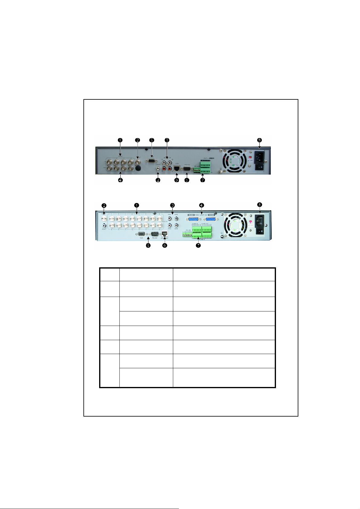
Rear Panel Description
Please refer to the connect description and connect to correct device.
DVR-470 Rear Panel
DVR-1670 Rear Panel
Index Physical Interface Description
1
Video Input
Video Output
2
Audio Output
3
Audio input
4
Video Loop out
VGA Interface
5
RS-232
Standard BNC connector.
Connect monitor, output video and menu.
1 channel RCA (1.0 Vp-p, 75Ω).
4 channel RCA (1.0 Vp-p, 75Ω).
DVR-1670 uses DB15 connectors.
DVR-470 uses on board BNC connectors.
VGA display.
Connect RS-232 devices. You may refer to
Appendix B of our manual to know the pin
definition.
2
Page 3
UTP Network
6
Interface
RS-485
External Alarm
7
Input
Connect to your switch or hub.
For PTZ camera connection. You may refer
to Appendix B of our manual to know the
pin definition.
4/8/16 Alarm in.
2/4 Alarm out
100V~240VAC
8
Relay Output
AC Input
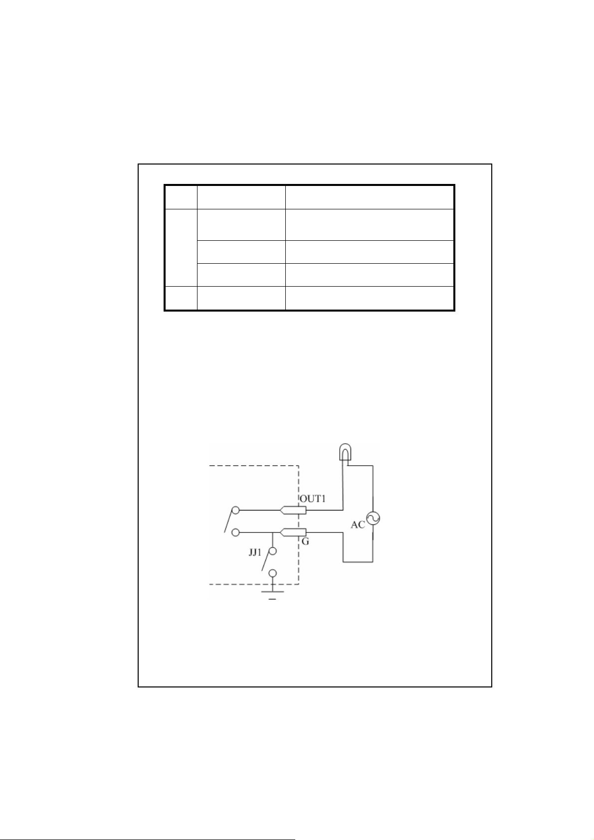
External Alarm In/Out Connection
Alarm input port:
G (GND):Connect the GND of sensor.
1~16:Alarm input, support normal open/normal close.
0:Reserved.
Alarm output:
1G~4G:4 relay output.
Alarm output connection
3
Page 4

Please note the usage of jumper JJ1. If you use DC, either of connections
is OK. We suggest you to use those DC under 12V, 1A.
If you use AC, please open the jumper. There are 4 jumpers (JJ1, JJ2, JJ3
and JJ4) in DVR main board, corresponding with 4 alarm output. The
default is closed.
Warning:If you use AC input for relay output, please open the jumpers.
Further Configuration
If you want to configure DVR-470/DVR-1670 and know the operation,
please refer to our manual in the CD disk.
2011-AB3480-000
4
 Loading...