

Page 1
Page 2

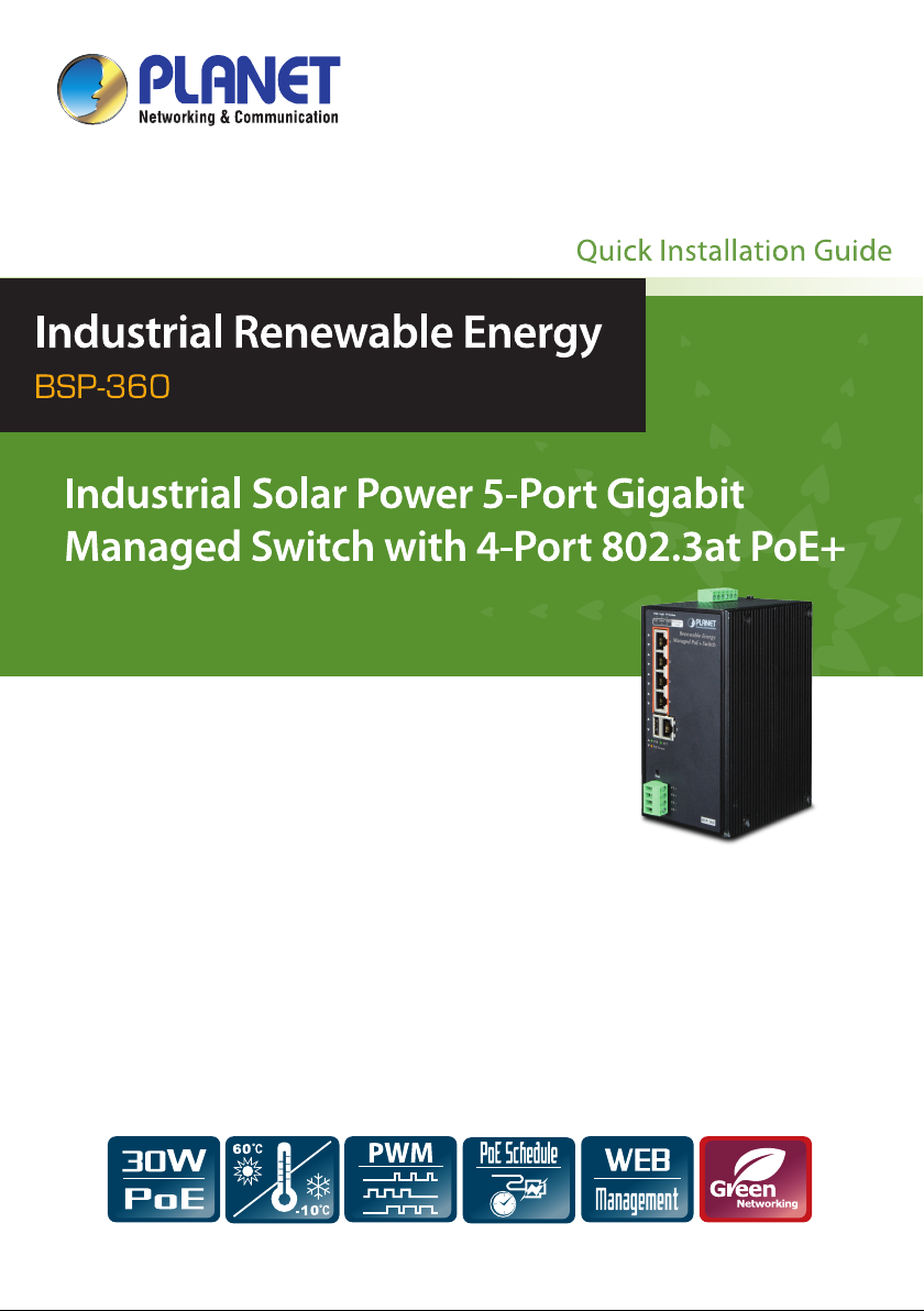
Industrial Renewable Energy
4-Port 10/100/1000T 802.3at PoE+
Managed Ethernet Switch
BSP-360
Quick Installation Guide
Page 3

Safety Precautions
Please read the following before using:
1. All electrical work must be done in accordance with local, and/or international
electrical codes.
2. Before installing or using this device, read all instructions and cautionary
marking located in (or on) this guide, the controller, the batteries, PV (Photovoltaic) array and any other device used.
3. To reduce the risk of short-circuits, use insulated tools when installing or working
with the inverter, the controller, the batteries, or any DC source (e.g., PV).
4. Remove all jewelry. This will greatly reduce the chance of accidental exposure to
live circuits.
5. The controller contains more than one live circuit (batteries and PV array).
Power may be present at more than one source.
6. This product contains no user serviceable parts. Do not attempt to repair this
unit unless fully qualied.
Page 4

Table of Contents
1. Package Contents ....................................................................................... 4
2. Requirements ............................................................................................. 5
3. Hardware Introduction ................................................................................ 6
3.1 Front Panel ......................................................................................... 6
3.2 LED Indicators..................................................................................... 7
3.3 Upper Panel ........................................................................................ 8
4. Hardware Installation .................................................................................10
5. Web Management ...................................................................................... 16
6. Customer Support .....................................................................................18
Appendix A: Recommended Use of the Connected Wires ....................................19
Appendix B: Recommended Settings for Different Batteries ................................20
Page 5
1. Package Contents
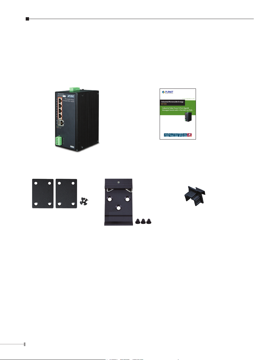
Thank you for purchasing PLANET Industrial Renewable Energy Managed PoE
Switch, BSP-360. Open the box of the BSP-360 and carefully unpack it. The box
should contain the following items:
1 x BSP-360 1 x Quick Installation Guide
1 x Wall Mounting Kit 1 x DIN Rail Kit 5 x RJ45 Dust Cap
If any of these are missing or damaged, please contact your dealer immediately. If
possible, retain the carton including the original packing materials to enable you to
repack the product in case there is a need to return it to us for repair.
4
Page 6
2. Requirements
PLANET BSP-360 provides a remote login interface for management purposes. The
following equipment is necessary for further management:
Workstation is installed with Ethernet NIC (Network Interface Card)
Choice of Internet browsers includes Windows XP/2003, Vista, Windows 7,
Windows 8, Windows 10, MAC OS X, Linux, Fedora, Ubuntu or other platforms
compatible with TCP/IP protocols.
The above workstation is installed with Web browser and JAVA runtime envi-
ronment plug-in.
Ethernet Port connection
Use standard network (UTP) cables with RJ45 connectors.
PV and battery
Two 12V batteries connected in series.
The maximum operating voltage of PV is 45V.
It is recommended to use Internet Explorer 8.0 or above to access
Note
the BSP-360.
5
Page 7
3. Hardware Introduction
3.1 Front Panel
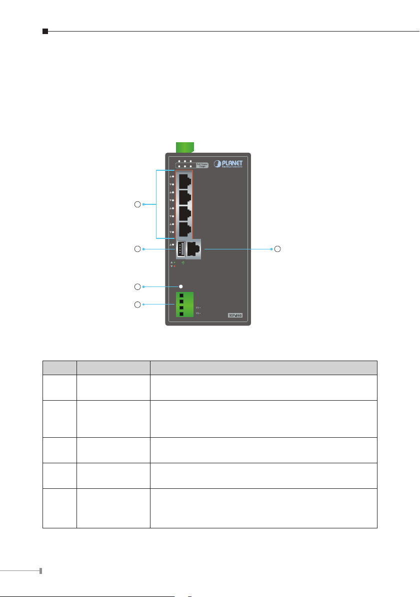
The front panel of the BSP-360 consists of 5 auto-sensing 10/100/1000Mbps
Ethernet RJ45 ports and one USB interface. The LED Indicators are also located on
the RJ45 ports of the BSP-360.
PWR Fault PV System
PoE Power
50W 100W 120W
Usage
Renewable Energy
1
Managed PoE+Switch
1
2
3
4
5
ACTLNK
PoE In-use
4
5
Reset
V1+
V2+
DC Out
BSP-360
23
Figure 3-1 shows the front panel of BSP-360
Item Interface Description
1 Port-1~Port-4
4 10/100/1000BASE-T RJ45 auto-MDI/MDI-X ports
with 802.af/at PoE+ injector function.
One 10/100/1000BASE-T RJ45 auto-MDI/MDI-X port.
2 Port-5
Port-5 functions as WAN port when the operation
mode of BSP-360 is congured to “Gateway mode”
3 USB
4 Reset Button
4-pin Terminal
5
Block
Connect the USB storage to USB port and back up
the conguration le.
< 5 seconds: System reboot.
> 5 seconds: Factory default.
24V DC output connector.
The output voltage is the same as battery voltage.
Maximum voltage is clamped at 24V, 1A.
6
Page 8
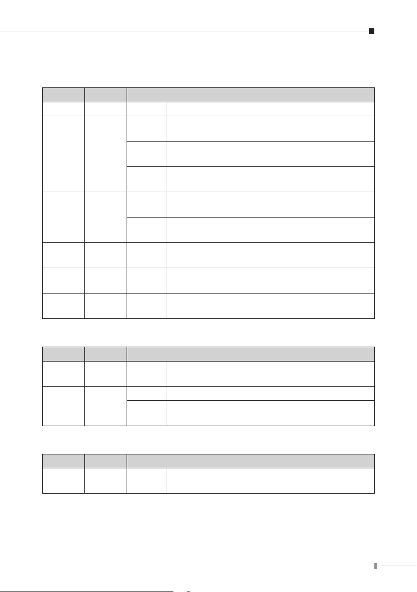
3.2 LED Indicators
System
LED Color Function
PWR Green On To indicate BSP-360 has power.
Slow
Blinks
Fault Green
PV
System
50W Green On
100W Green On
120W Green On
PoE 10/100/1000BASE-T Interfaces (Port-1 to Port-4)
Green
Fast
Blinks
On
Slow
Blinks
Fast
Blinks
To indicate the PV is disconnected.
To indicate the battery voltage is less than the
value for low voltage disconnection.
To indicate bad battery, over-current or
short-circuit.
To indicate the system is “on”.
To indicate the battery is “charging”.
To indicate the system consumes over 50-watt
PoE power budget.
To indicate the system consumes over 100-watt
PoE power budget.
To indicate the system consumes the total
120-watt PoE power budget.
LED Color Function
LNK/
ACT
PoE Orange
10/100/1000BASE-T Interfaces (Port-5)
LED Color Function
LNK/
ACT
Green Blinks
Lights To indicate the port is providing DC in-line power.
Off
Green Blinks
To indicate the link through that port is
successfully established.
To indicate the connected device is not a PoE
Powered Device (PD).
To indicate the link through that port is
successfully established.
7
Page 9
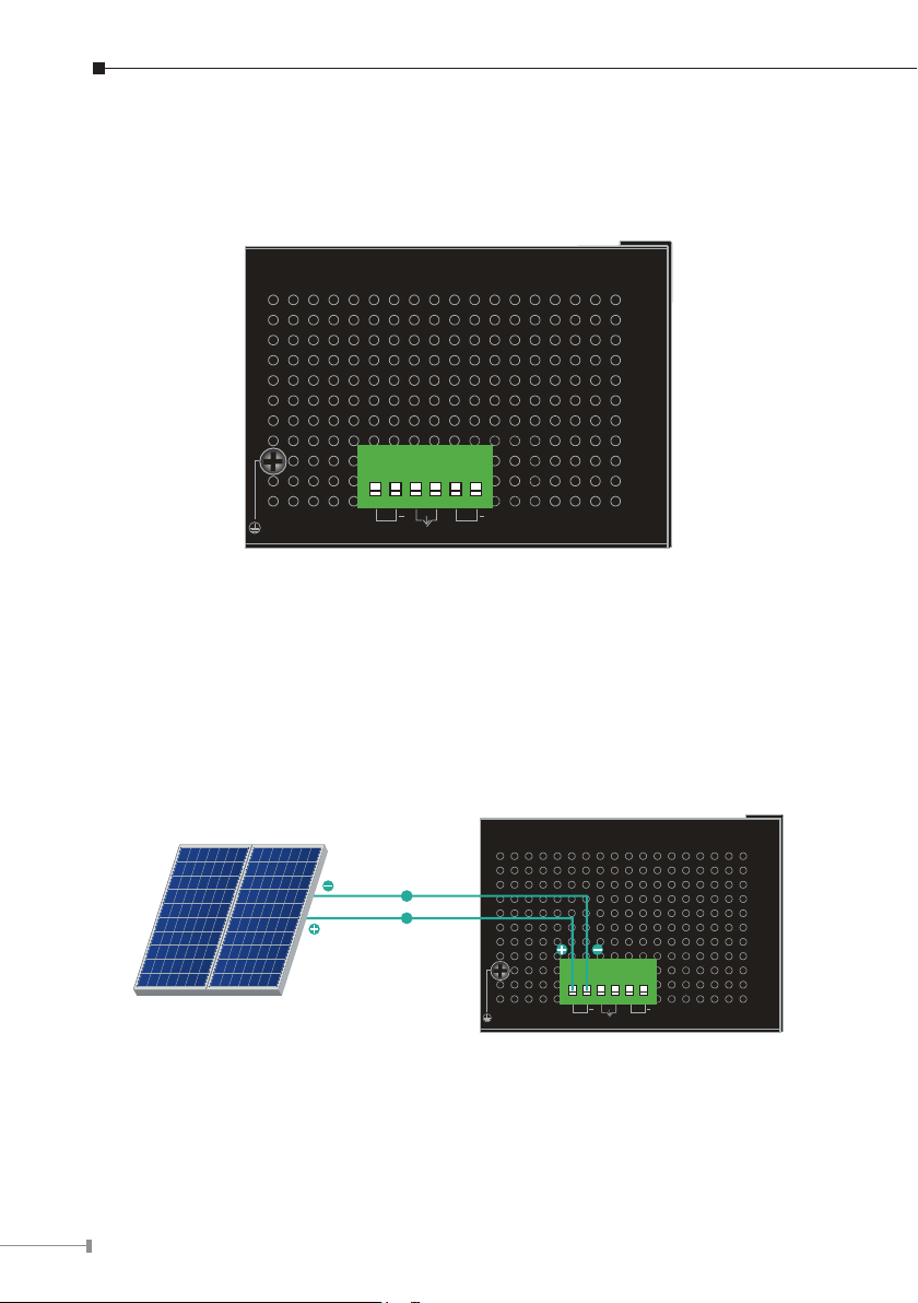
3.3 Upper Panel
The upper panel of the BSP-360 consists of one terminal block connector with PV
and battery power inputs.
1 2 3 4 5 6
+ +
PV DC 24~45V
The input voltage range of each interface is shown as follows:
PV In Connector
24~45V DC
Alarm
PV
Bat.
Bat. DC 24V
Figure 3-2 Upper Panel
DC
DC
24~45V DC
1 2 3 4 5 6
Solar PV
PV DC 24~45V
+ +
Alarm
Bat.
PV
Bat. DC 24V
Figure 3-3 PV In Connector
8
Page 10
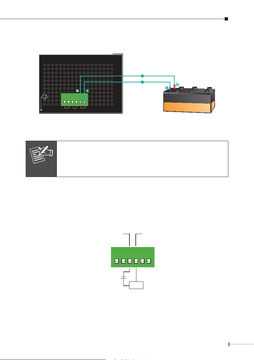
Battery In/Out
24V DC
1 2 3 4 5 6
PV DC 24~45V
+ +
Alarm
Bat.
PV
The wire gauge for the terminal block should be in the range from
14 to 24 AWG.
Note
DO Connectors
Level 0: -24V~2.1V (±0.1V)
Level 1: 2.1V~24V (±0.1V)
DC
DC
24V DC
Bat. DC 24V
Battery
Figure 3-4 Battery In/Out
DO
5~24VDC
GND
1 2 3 4 5 6
Load
9
Page 11
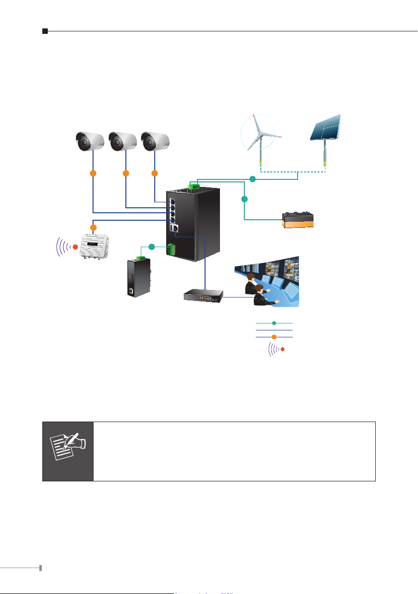
4. Hardware Installation
The following section describes the hardware installation of the BSP-360. Before
connecting any network device to the BSP-360, read this chapter carefully.
CAM1 CAM2 CAM3
Turbine
PoE PoE PoE
PoE
N
DC
DC
DC
Battery
BSP-360
Wireless CPE/AP
Media Converter/
DC Powered Device
Ethernet Switch
Monitoring Center
DC
PoE
N
Power Line (DC)
1000BASE-T UTP
1000BASE-T UTP with PoE
2.4GHz 802.11n
Please follow the following steps to install the system:
Step 1. Install BSP-360
Place the BSP-360 in a desired location using the wall-mount xtures.
a. Please install the BSP-360 in a proper enclosure or shelter.
b. The BSP-360 must be grounded.
Note
Solar PV
10
Page 12
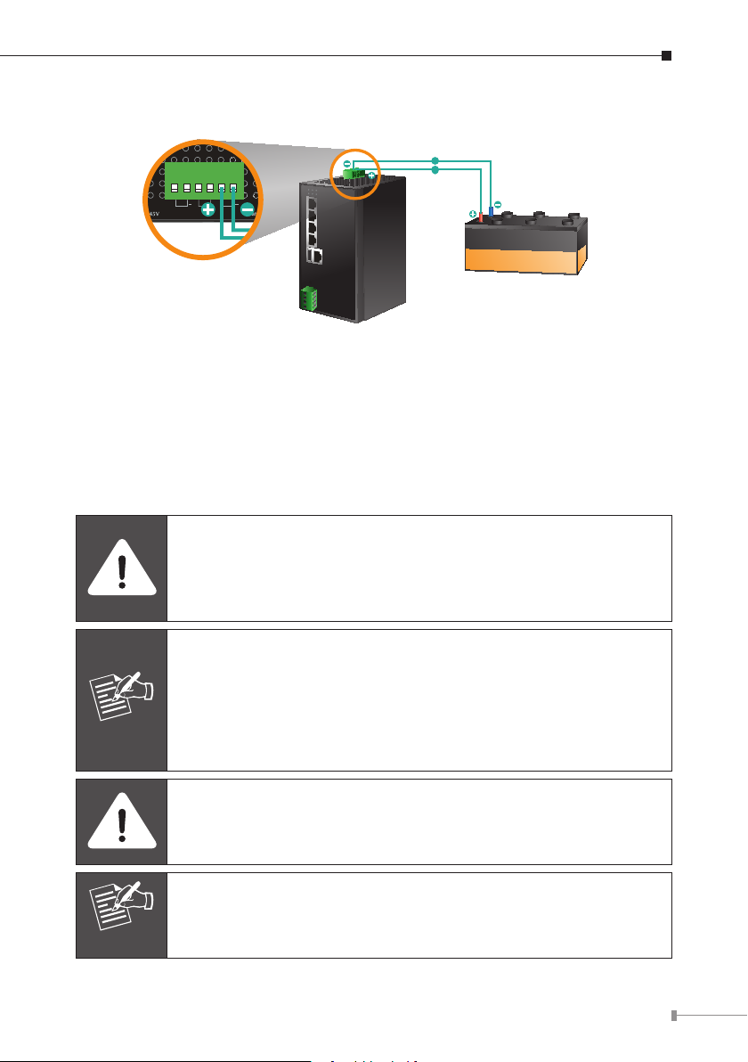
Step 2. Install battery
Bat.
PV
Alarm
+ +
1 2 3 4 5 6
DC
DC
Bat.In/Out
Battery
1. Connect the negative electrode of the battery to the terminal for the negative
electrode of the battery on the BSP-360.
2. Connect the positive electrode of the battery to the terminal for the positive
electrode of the battery on the BSP-360.
3. After the battery is well connected to the BSP-360, the PWR LED will be ON
and System LED will slowly blink, and Fault LED will slowly blink for PV
not connected.
The BSP-360 accepts the 24V DC battery system. Please pay
attention to the battery characteristics and also refer to the section
-- Recommended Settings for Different Batteries in the Quick
Installation Guide.
Note
Note
Be noted for the thickness of electric wire and please refer to the
section -- Recommended Use of the Connected Wires in the
Quick Installation Guide.
The default LVD (Low Voltage Disconnection) is set at 22.2V
DC; we suggest charge the voltage of battery to 23.5V DC or
above for the BSP-360.
Check the total power consumption of your connected network
device before installation. Improper battery capacity could shorten
the battery life or make your network device lack of power supply.
Please link PLANET download center and download BSP-
360-PV&BAT_calculation. The calculation list can help you to
select solar panel and battery.
11
Page 13
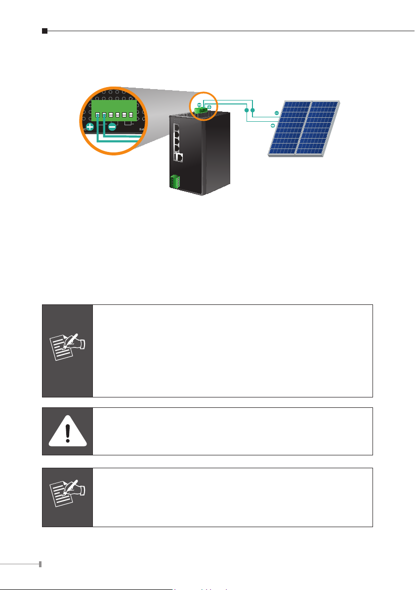
Step 3. Install PV Panel
Bat.
PV
Alarm
+ +
1 2 3 4 5 6
DCDC
PV In
Solar PV
1. Connect the negative electrode of the PV panel to the terminal for the negative
electrode of the PV panel on the BSP-360.
2. Connect the positive electrode of the PV panel to the terminal for the positive
electrode of the PV panel on the BSP-360.
3. After the PV is well connected to the BSP-360 and providing 24V or above
voltage, the System LED will blink fast for battery charge if the battery is not
full. And Fault LED will turn off.
Be noted for the thickness of electric wire and please refer to the
section -- Recommended Use of the Connected Wires in the
Quick Installation Guide.
Check the total power consumption of your device and the
Note
sunshine duration of your area from the weather bureau for a
proper PV. Improper PV could shorten the battery life or provide
insufficient power to the BSP-360.
12
Note
The BSP-360 supports a maximum of 45V DC input.
Please link PLANET download center and download BSP-
360-PV&BAT_calculation. The calculation list can help you to
select solar panel and battery.
Page 14
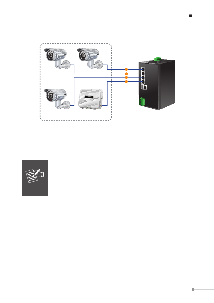
Step 4. Connect 802.3af/802.3at PoE Device
PoE
PoE
PoE
PoE
802.3af/at PoE Device
1. Connect the PoE devices to ports 1~4 on the BSP-360.
2. Check the PoE-in-Use LED. If the network devices such as PoE camera and PoE
wireless AP are powered, the PoE-in-use LED will turn ON and Link/Act LED
will blink for a successful connection or data receiving.
Please use Cat5/5e or above cable and the maximum distance
should within 100 meters.
If the Network devices are installed outdoors, please consider to
Note
install a lightening arrestor to protect the network device and the
BSP-360.
13
Page 15
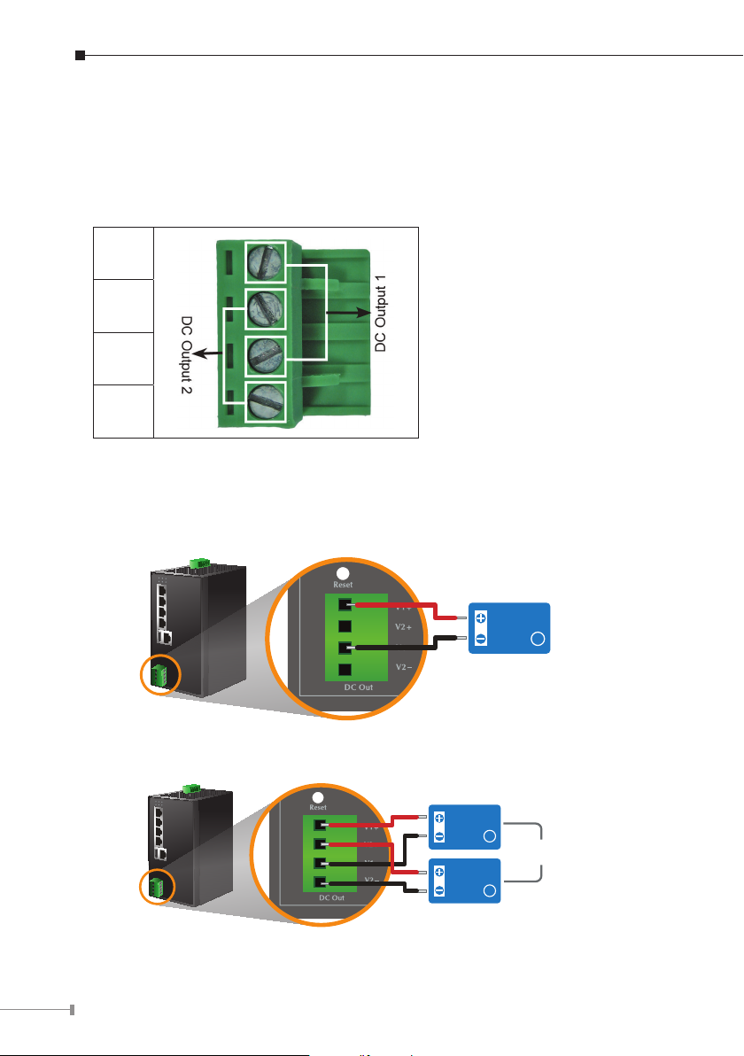
Step 5. Wiring the DC Outputs
Please follow the steps below to insert the power wires for DC power required
equipment.
1. Please nd the terminal block connector with two DC power outputs shown
below:
V1+
V2+
V1-
V2-
2. Insert the Positive and Negative DC wires into the V+ and V- terminals, respectively; Terminals 1 and 3 for Power 1, and Terminals 2 and 4 for Power 2.
3. Connect the other points of DC power wires to the power devices. Tighten the
wire-clamp screws for preventing the wires from loosening.
14
V1+
V2+
V1-
V2-
One Powered Device
V1+
V2+
V1-
V2-
Two Powered Devices
Powered
Device
Maximum Output 24 Watts
Powered
Device
1
Total Maximum
Powered
Device
Output 24 Watts
2
1
Page 16
4. Install the terminal block on the BSP-360.
The voltage of DC out is based on the battery voltage and the
maximum DC out from the BSP-360 is 24VDC, 1A.
The wire gauge for the terminal block should be in the range
Note
from 14 to 24 AWG.
The external device should also be grounded properly.
Please ensure the output voltage is correct for remote device.
Otherwise, it will damage your remote device.
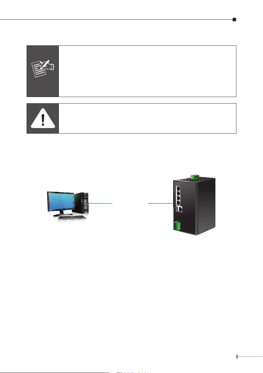
Step 6. Connect to PC
RJ45/UTP Cable
IP Address:
192.168.0.x
IP Address:
192.168.0.100
After completing the above 6 steps, the BSP-360 is ready for service.
15
Page 17
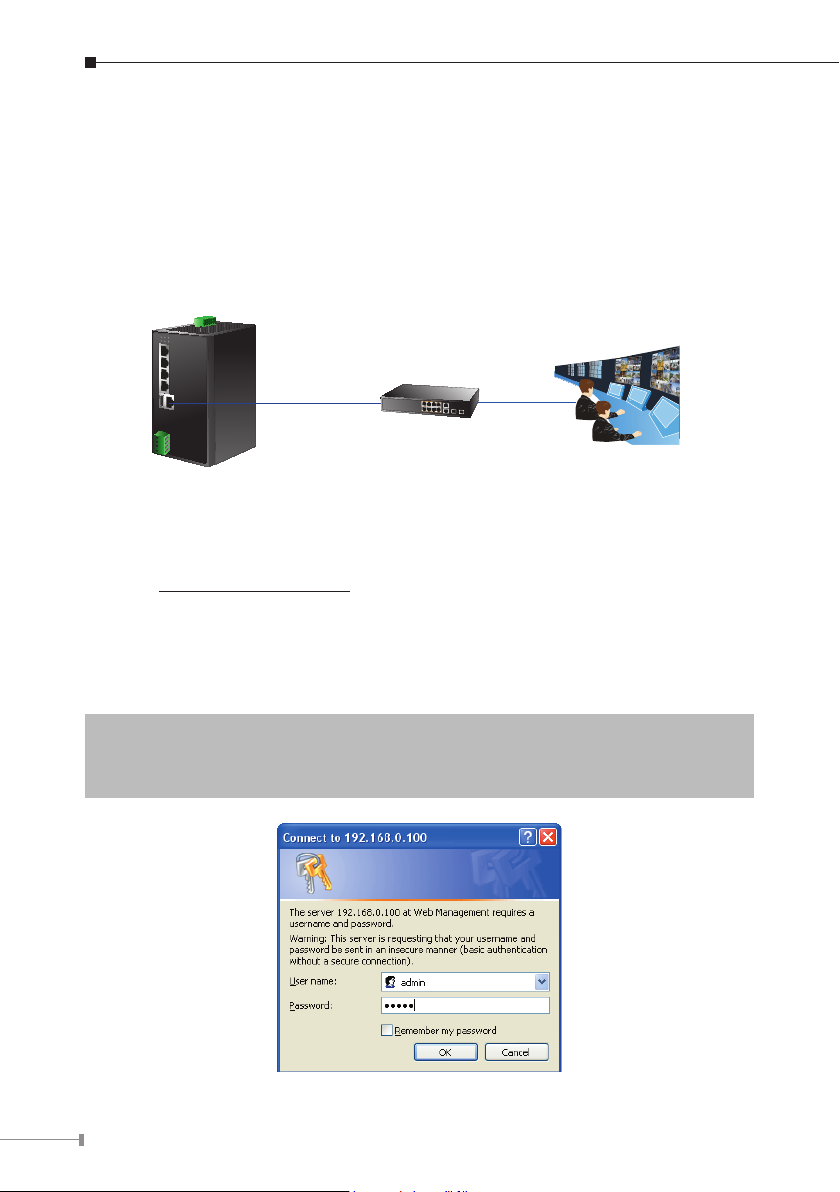
5. Web Management
The following shows how to start up the Web Management of the BSP-360. Note
the BSP-360 is congured through an Ethernet connection. Please make sure the
manager PC must be set to the same IP subnet address.
For example, the default IP address of the BSP-360 is 192.168.0.100, then the
manager PC should be set to 192.168.0.x (where x is a number between 1 and
254, except 100), and the default subnet mask is 255.255.255.0.
Ethernet Switch
Monitoring Center
BSP-360
Logging in to the BSP-360
Step 1. Use Internet Explorer 8.0 or above for Web browser and enter IP address
http://192.168.0.100 (the factory-default IP address) to access the
Web interface.
Step 2. When the following dialog box appears, please enter the default user
name “admin” and password “admin” (or the password you have
changed before).
Default IP Address: 192.168.0.100
Default User Name: admin
Default Password: admin
16
Page 18
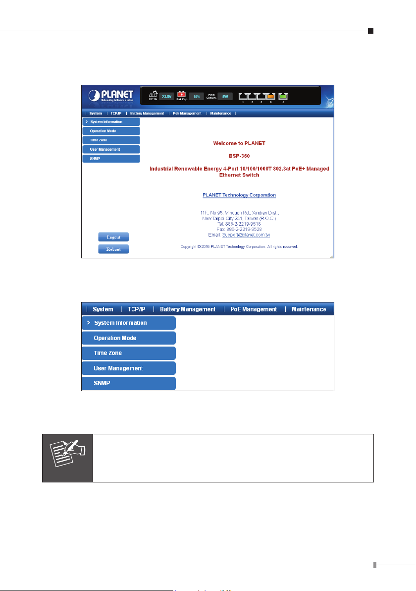
Step 3. After entering the password, the main screen appears. The above banner
shows the information of DC IN, Battery and Power Consumption.
Step 4. The Switch Menu on the left of the Web page lets you access all the
functions and status the BSP-360 provides.
Now, you can use the Web management interface to continue the Switch
management. Please refer to the user manual for more understanding.
For security reason, please change and memorize the new password after this first setup.
Note
17
Page 19
6. Customer Support
Thank you for purchasing PLANET products. You can browse our online FAQ
resource on PLANET web site rst to check if it could solve your issue. If you need
more support information, please contact PLANET switch support team.
Switch support team mail address:
[email protected]
BSP-360 User’s Manual:
http://www.planet.com.tw/en/support/download.php?type1=22153&model=48944&
type=3
BSP-360 PV&BAT Calculation:
http://www.planet.com.tw/en/support/faq.php?key=%5BBSP-360%5D%20
PV%26BAT-Calculation
Copyright © PLANET Technology Corp. 2016.
Contents are subject to revision without prior notice.
PLANET is a registered trademark of PLANET Technology Corp.
All other trademarks belong to their respective owners.
18
Page 20

Appendix A: Recommended Use of the Connected Wires
(Applicable to the system with voltage attenuation less than 3%) The following
table is applicable to the applications in the system.
Distance in feet ( meters )
Amps 24 AWG 22 AWG 20 AWG 18 AWG 16 AWG 14 AWG
2.5
5.0
7.5
10
12.5
15
5.6 ft
(1.95m)
2.80 ft
(0.86m)
1.86 ft
(0.56m)
1.40 ft
(0.42m)
1.12 ft
(0.34m)
0.94 ft
(0.28m)
8.8 ft
(2.70m)
4.4 ft
(1.36m)
2.96 ft
(0.90m)
2.22ft
(0.68m)
1.78ft
(0.54m)
1.48 ft
(0.46m)
14.12 ft
(4.30m)
7.06 ft
(2.16m)
4.70 ft
(1.44m)
3.52 ft
(1.08m)
2.82 ft
(0.86m)
2.36 ft
(0.72m)
22.50 ft
(6.86 m)
11.26 ft
(3.42m)
7.50 ft
(2.28m)
5.62 ft
(1.72m)
4.50 ft
(1.38m)
3.76 ft
(1.14m)
36.0 ft
(11.0m)
18.0 ft
(5.48m)
12.0 ft
(3.66m)
9.0 ft
(2.74m)
7.20 ft
(2.20m)
6.0 ft
(1.82m)
56.4 ft
(17.22m)
28.2 ft
(8.6m)
18.82 ft
(5.74m)
14.12 ft
(4.30m)
11.30 ft
(3.44m)
9.42 ft
(2.86m)
19
Page 21

Appendix B: Recommended Settings for Different Batteries
We suggest Nickel-cadmium battery and Lead-acid battery for BSP-360. You could
set the Battery type at Battery Management on the web.
Description Specications
Battery type Nickel-cadmium Battery
System voltage 24V
Maximum input voltage 45V DC
Output voltage for load Equal to battery’s voltage
Float charge voltage 27.2V DC (26.0~30.0V)
Absorption charge voltage 29.2V DC (28.0~32.0V)
LVD (Low Voltage
Disconnection)
22.2V DC (21.0~25.0V)
LVR (Low Voltage
Reconnection)
Temperature compensation
Baseline@25°C
Battery type Lead-acid Battery (Default Setting)
System voltage 24V
Maximum input voltage 45V DC
Output voltage for load Equal to battery’s voltage
Float charge voltage 27.2V DC (26.0~30.0V)
Absorption charge voltage 29.2V DC (28.0~32.0V)
LVD (Low Voltage
Disconnection)
LVR (Low Voltage
Reconnection)
Temperature compensation
Baseline@25°C
24.8V DC (23.0~27.0V)
±40 mV/°C for NiCad type batteries, Charge
cut-off @ 55°C
22.2V DC (21.0~25.0V)
24.8V DC (23.0~27.0V)
±60 mV/°C for lead acid type batteries, Charge
cut-off @ 55°C
20
Page 22

 Loading...