

Page 1

`
25M Infrared Internet Camera
ICA-312
User’s Manual
Version: 1.00
Date: June. 2007
1/57
Page 2

Copyright
Copyright © 2007 by PLANET Technology Corp. All rights reserved. No part of this publication
may be reproduced, transmitted, transcribed, stored in a retrieval system, or translated into any
language or computer language, in any form or by any means, electronic, mecha nical, magnetic,
optical, chemical, manual or otherwise, without the prior written permission of PLANET.
PLANET makes no representations or warranties, either expressed or implied, with respect to
the contents hereof and specifically disclaims any warranties, merchantability or fitness for any
particular purpose. Any software described in this manual is sold or licensed "as is". Should the
programs prove defective following their purchase, the buyer (and not PLANET, its distributor, or
its dealer) assumes the entire cost of all necessary servicing, repair, and any incidental or
consequential damages resulting from any defect in the software. Further, PLANET reserves the
right to revise this publication and to make changes from time to time in the contents hereof
without obligation to notify any person of such revision or changes.
All brand and product names mentioned in this manual are trademarks and/or
registered trademarks of their respective holders.
Federal Communication Commission Interference Statement
This equipment has been tested and found to comply with the limits for a Class B digital device,
pursuant to Part 15 of FCC Rules. These limits are designed to provide reasonable protection
against harmful interference in a residential installation. This equipment generates, uses, and
can radiate radio frequency energy and, if not installed and used in accordance with the
instructions, may cause harmful interference to radio communications. However, there is no
guarantee that interference will not occur in a particular installation. If this equipment does cause
harmful interference to radio or television reception, which can be determined by turning the
equipment off and on, the user is encouraged to try to correct the interference by one or more of
the following measures:
1. Reorient or relocate the receiving antenna.
2. Increase the separation between the equipment and receiver.
3. Connect the equipment into an outlet on a circuit different from that to which the receiver
is connected.
4. Consult the dealer or an experienced radio technician for help.
FCC Caution
To assure continued compliance. (example-use only shielded interface cables when connecting
to computer or peripheral devices). Any changes or modifications not expressly approved by the
party responsible for compliance could void the user’s authority to operate the equipment.
This device complies with Part 15 of the FCC Rules. Operation is subject to the Following two
conditions: ( 1 ) This device may not cause harmful interference, and ( 2 ) this Device must
accept any interference received, including interference that may cause undesired operation.
Federal Communication Commission (FCC) Radiation Exposure Statement
This equipment complies with FCC radiation exposure set forth for an uncontrolled
environment. In order to avoid the possibility of exceeding the FCC radio frequency exposure
limits, human proximity to the antenna shall not be less than 20 cm (8 inches) during normal
operation.
R&TTE Compliance Statement
1/57
Page 3

This equipment complies with all the requirements of DIRECTIVE 1999/5/CE OF THE
EUROPEAN PARLIAMENT AND THE COUNCIL OF 9 March 1999 on radio equipment
and telecommunication terminal Equipment and the mutual recognition of their
conformity (R&TTE)
The R&TTE Directive repeals and replaces in the directive 98/13/EEC
(Telecommunications Terminal Equipment and Satellite Earth Station Equipment) As of
April 8,2000.
Safety
This equipment is designed with the utmost care for the safety of those who in st all and use it.
However, spe cial attention must be paid to the dangers of electric shock and static electricity
when working with electrical equipment. All guidelines of this and of the computer
manufacture must therefore be allowed at all times to ensure the safe use of the equipment
CE Mark Warning
This is a Class A product. In a domestic environment, this product may cause radio
interference, in which case the user may be required to take adequate measures.
WEEE Regulation
To avoid the potential effects on the environment and human health as a result of the
presence of hazardous substances in electrical and electronic equipment, end users
of electrical and electronic equipment should understand the meaning of the
crossed-out wheeled bin symbol. Do not dispose of WEEE as unsorted municipal
waste and have to collect such WEEE separately.
Revision
User’s Manual for PLANET 25M Infrared Internet Camera
Model: ICA-312
Rev: 1.0 (June. 2007)
Part No. EM-ICA312
.
2/57
Page 4

Table of Content
1. Introduction................................................................................................................ 5
1.1 Overview............................................................................................................. 5
1.2 Features.............................................................................................................. 5
1.3 Package Contents............................................................................................. 5
2. Basic Setup...............................................................................................................7
2.1 System Requirements....................................................................................... 7
2.2 Physical Details.................................................................................................. 7
2.3 Hardware Installation........................................................................................8
2.4 Initial Utility Installation ..................................................................................... 8
2.5 IPWizard............................................................................................................ 11
2.6 Configure With IPWizard................................................................................ 13
2.7 Using UPnP of Windows
2.8 Setup ActiveX to use the ICA-312................................................................ 20
3. Web-based Management...................................................................................... 22
3.1 Introduction....................................................................................................... 22
3.2 Connecting to ICA-312 ................................................................................... 22
3.3 Live View........................................................................................................... 24
3.4 ActiveX Control ................................................................................................ 24
3.4.1 Digital Zoom.......................................................................................... 25
3.4.2 Record.................................................................................................... 25
3.4.3 Snapshot................................................................................................ 26
3.4.4 Statistics................................................................................................. 26
3.4.5 About......................................................................................................27
3.5 System Setting................................................................................................. 27
3.5.1 Network.................................................................................................. 28
3.5.2 DDNS server......................................................................................... 29
3.5.3 PPPoE.................................................................................................... 30
3.5.4 3GPP...................................................................................................... 32
3.5.5 UPnP...................................................................................................... 33
3.6 Camera.............................................................................................................. 34
3.7 System............................................................................................................... 34
3.7.1 Date & Time...........................................................................................34
3.7.2 Maintenance.......................................................................................... 36
3.8 Video.................................................................................................................. 37
3.8.1 MPEG4/VGA......................................................................................... 37
3.8.2 MPEG4/QVGA...................................................................................... 38
3.8.3 MPEG4/QQVGA................................................................................... 39
3.8.4 JPEG/QVGA......................................................................................... 40
3.9 User ................................................................................................................... 41
3.10 E-Mail..............................................................................................................42
3.11 FTP .................................................................................................................. 42
3.12 Object detection............................................................................................. 43
Appendix A: Hardware Restore....................................................................................45
Appendix B: Troubleshooting & FAQ .......................................................................... 46
®
XP™.................................................................... 16
3/57
Page 5

Appendix C: PING IP Address ..................................................................................... 50
Appendix D: Bandwidth Estimation............................................................................. 51
Appendix E: DDNS Application.................................................................................... 52
4/57
Page 6

1. Introduction
This 25M Infrared Internet Camera is an inexpensive fully scalable surveillance technology.
Because the 25M Infrared Internet Cameras can be plugged into your existing local area network
infrastructure, you will potentially save thousands of dollars on unnecessary cabling.
The 25M Infrared Internet Camera is accessible via the LAN or Internet connection. Connect your
25M Infrared Internet Camera directly to a local area network or xDSL modem, and with Microsoft
Internet Explorer you get instant, on demand video streams. Within minutes you can set up the
25M Infrared Internet Camera to capture a video sequence to a PC. The live video image can be
uploaded to a website for the world to see or made available only to select users on the network.
1.1 Overview
This user’s manual explains how to operate the 25M Infrared Internet Camera from a computer.
Basically, the user’s manual is written to be read on the computer display. However, users might
consider printing it out to access easily and read it before you operate the Network Camera.
1.2 Features
z High quality 1/3 inch color CCD sensor of 25M IR distance
z Clear and high-image quality pictures in the daytime and at night
z 3GGP for 3G mobile remote application
z Multi-profile encoder supports MPEG-4 and M-JPEG video compression simultaneously
z LED used on ICA-312 are 4 times brighter than ordinary IR LED
z Special mental base enhances lighting and dissipates heat
z Weather-proof protection housing against the various weather
z Plug-N-Watch is able to simplify system integration in an existing network environment
z Because of supporting TCP/IP networking, SMTP e-mail, and HTTP public network
standards, ICA-312 can be applied and utilized to a mixed IP network environment
z Easy configuration: the network administrator can configure and manage ICA-312 via
Windows-based utility or web interface
z DDNS, PPPoE, FTP upload supports provide more alternative in your surveillance network
z Motion Detection, the motion detection feature can monitor any suspicious movement in
specific area
1.3 Package Contents
User can find the following items in the package:
1. ICA-312 x 1
2. Power adapter x 1
3. Wall mount accessories x 1
5/57
Page 7

4. User’s manual and Utility CD x 1
5. Software CD x 1
6. Quick Start Guide x 1
NOTE:
1. If any of the above items are missing, please contact your dealer immediately.
2. Using the power supply that is not the one included in ICA-312 packet will cause damage and
void the warranty for this product.
6/57
Page 8
2. Basic Setup
This chapter provides details of installin g and configuring the ICA-312
2.1 System Requirements
Network Interface 10/100MBase-TX Ethernet
Monitoring System Recommended for Internet Explorer 6.0 or later
System Hardware · CPU: Pentium 4, 1.5GHz or above
· Memory Size : 512 MB (512 MB or above Recommended )
· VGA card resolution : 1024 x 768 or above
· Network bandwidth: In VGA resolution mode, minimum
upload bandwidth is 1Mbps.
System Requirement For Viewer & Recorder Application
Support OS Win 2000 , Win XP
System Hardware 16 cameras surveillance application
· CPU: Pentium 4, 2.8GHz or faster
· Memory Size : 512 MB or above
· VGA card resolution : 1024 x 768 or above
· Free space of hard disk: 10GB or higher
· Power Supply: 300W or higher
Note: The listed information is minimum system requirements only. Actual requirement will vary
depending on the nature of your environment.
2.2 Physical Details
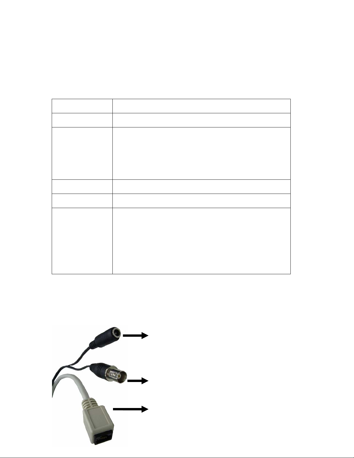
z Power Connector – Connect to DC 12V power
adapter.
z BNC Connector – For analog v i deo output.
z RJ-45 Connector – For connect a CAT5 cable to hub
or switch.
7/57
Page 9

Cable Connections:
1. Power Connector: The input power is 12VDC.
Note: Supplies the power to the ICA-312 with the power adapter included in package.
2. Video Output Connector (BNC port)
The ICA-312 also provides composite video output. User can use BNC video cable to
connect the ICA-312 with a TV monitor or DVR.
3. RJ-45 LAN Connector: For connect a LAN cable to your Hub/Switch.
The LAN port is a RJ-45 connec tor for connections to 10Base-T Ethernet or 100Base-TX
Fast Ethernet cabling. This Ethernet port built N-Way protocol can detect or negotiate the
transmission speed of the network automatically. Please use Category 5 “straight” cable to
connect the ICA-312 to a 100Mbps Fast Ethernet network switch or hub.
Note: In case you need to connect the device to PC or notebook directly, you should use a
cross-over cable instead.
2.3 Hardware Installation
1. Fix ICA-312 to the location with wall mount fixture.
2. Plug-in Ethernet Cable into RJ-45 LAN port. Connect an Ethernet cable to the LAN port on the
ICA-312 and connect the other side of the Ethernet cable to a hub/switch.
3. Connect the attached power adapter to camera and plug-in this adapter into power outlet.
4. Connect Video BNC connector to a local TV monitor or DVR if necessary.
5. Done.
2.4 Initial Utility Installation
Insert the bundled CD into the CD-ROM drive to launch the autorun program. Once completed, a
welcome menu screen will appear.
Click the “IPWizard Utility” hyperlink in the welcome screen, the below InstallShield Wizard dialog
box will appear.
Note: If the welcome screen does not appear, click “Start” at the taskbar. Then, select “Run” and
type “D:\Utility\setup.exe”, assume D is your CD-ROM drive.
8/57
Page 10
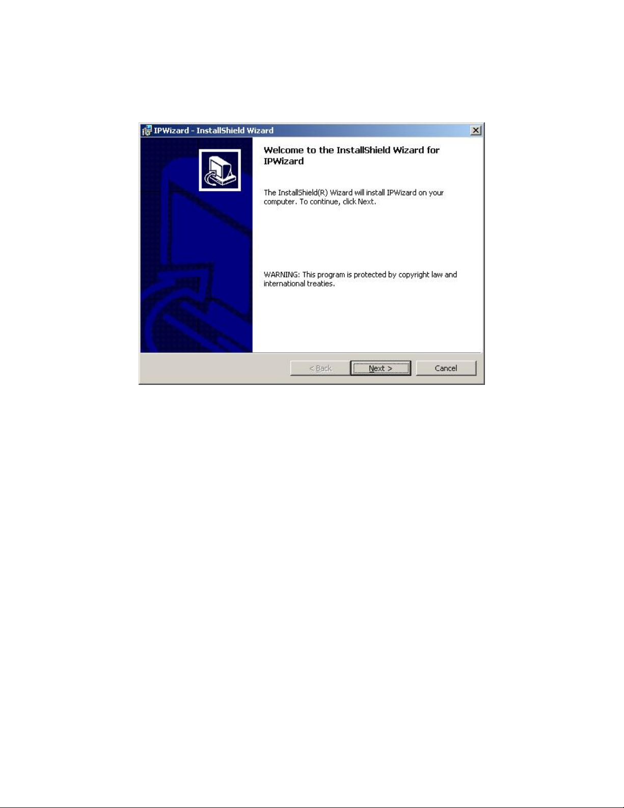
The “Welcome to the InstallShield Wizard for IPWizard” will display on the screen and click “Next”
to continue.
9/57
Page 11
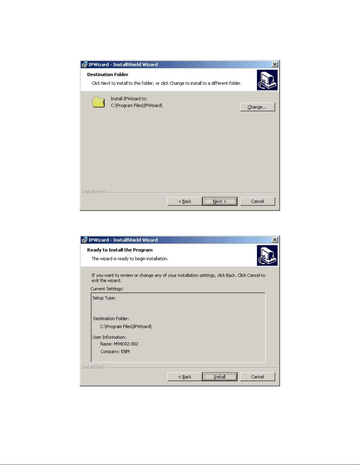
Please click “Next” to install with original settings, or you may click “Change…” button to modify
the install folder then press “Next” to continue.
Please click “Install” to start the installation.
10/57
Page 12
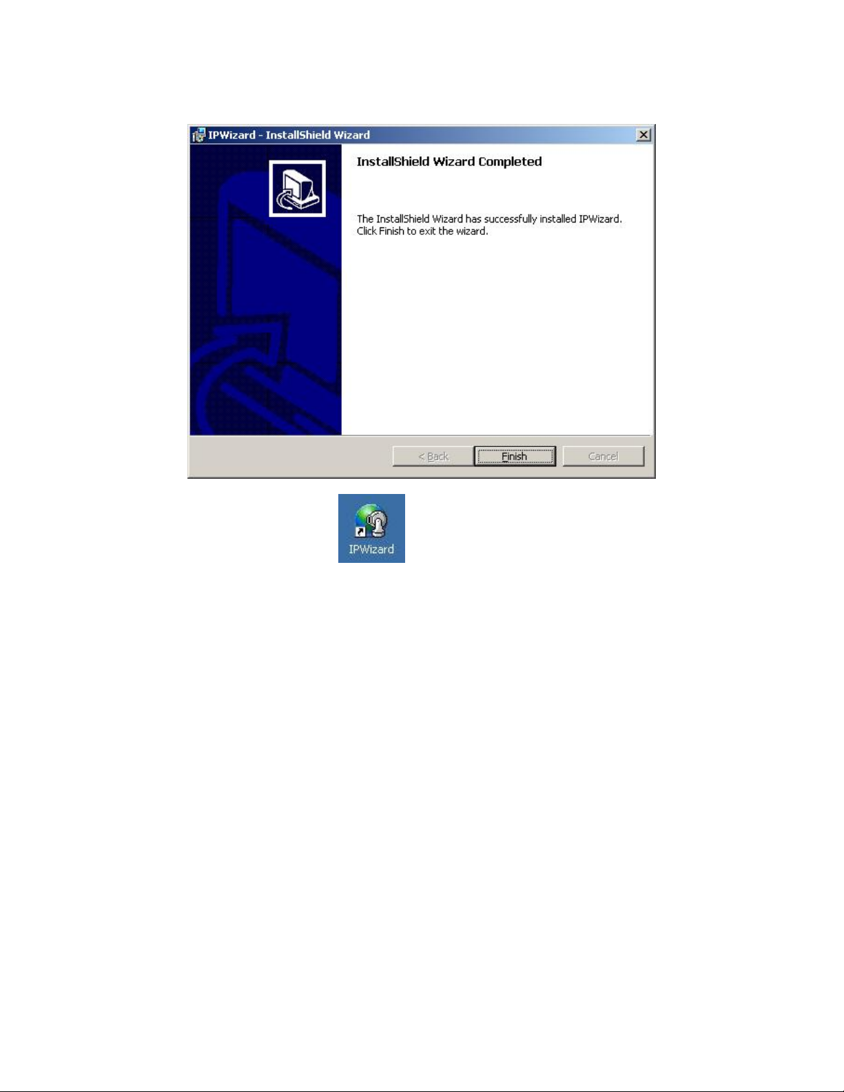
Please click “Finish” to complete the driver installation
Please double-click the utility icon
initial utility - IPWizard. Please refer to the next section to operate this utility to finish the initial
configuration of your ICA-312.
on the desktop, and then you will see the ICA-312
2.5 IPWizard
When you installed the ICA-312 on a LAN environment, you may execute IPWizard to discover
ICA-312’s IP address and set up related parameters in the ICA-312.
Search Button:
When click Search button, a searching window will pop up. IPWizard is starting to search ICA-312
on the LAN. The message “No Network Devices Is Found” will appear on this window if IPWizard
cannot find any camera on the LAN. Otherwise, existed cameras will be listed. If total quantity is
over, please move the cursor to Information Box. Click on the left button of the mouse and the
Information Box of the Listing Window will roll upward automatically; on the contrary, move the
cursor to the Information Box on the top of Listing Window and click on the left button of the mouse
and Listing Window will roll downward.
11/57
Page 13
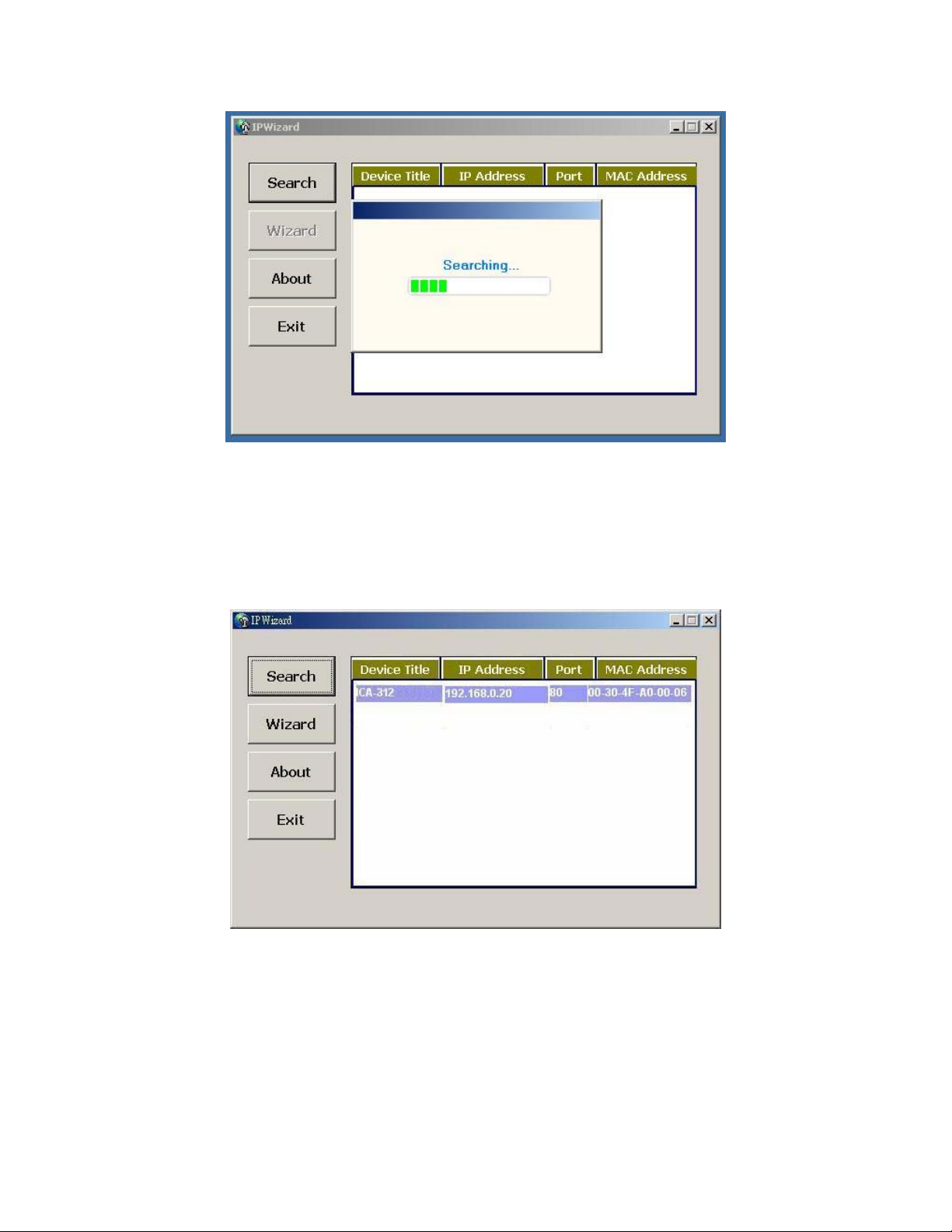
Wizard Button:
If IPWizard finds your camera, Wizard button will become available. Please select the device you
would like to configure in the Information Box. The device will turn into yellow which means this
device is selected; please press “Wizard” button. Or you coul d double click the mouse left key on
the selected camera. Relative settings will be carried out. Details of Install Wizard will be specified
as Section 2.6.
12/57
Page 14
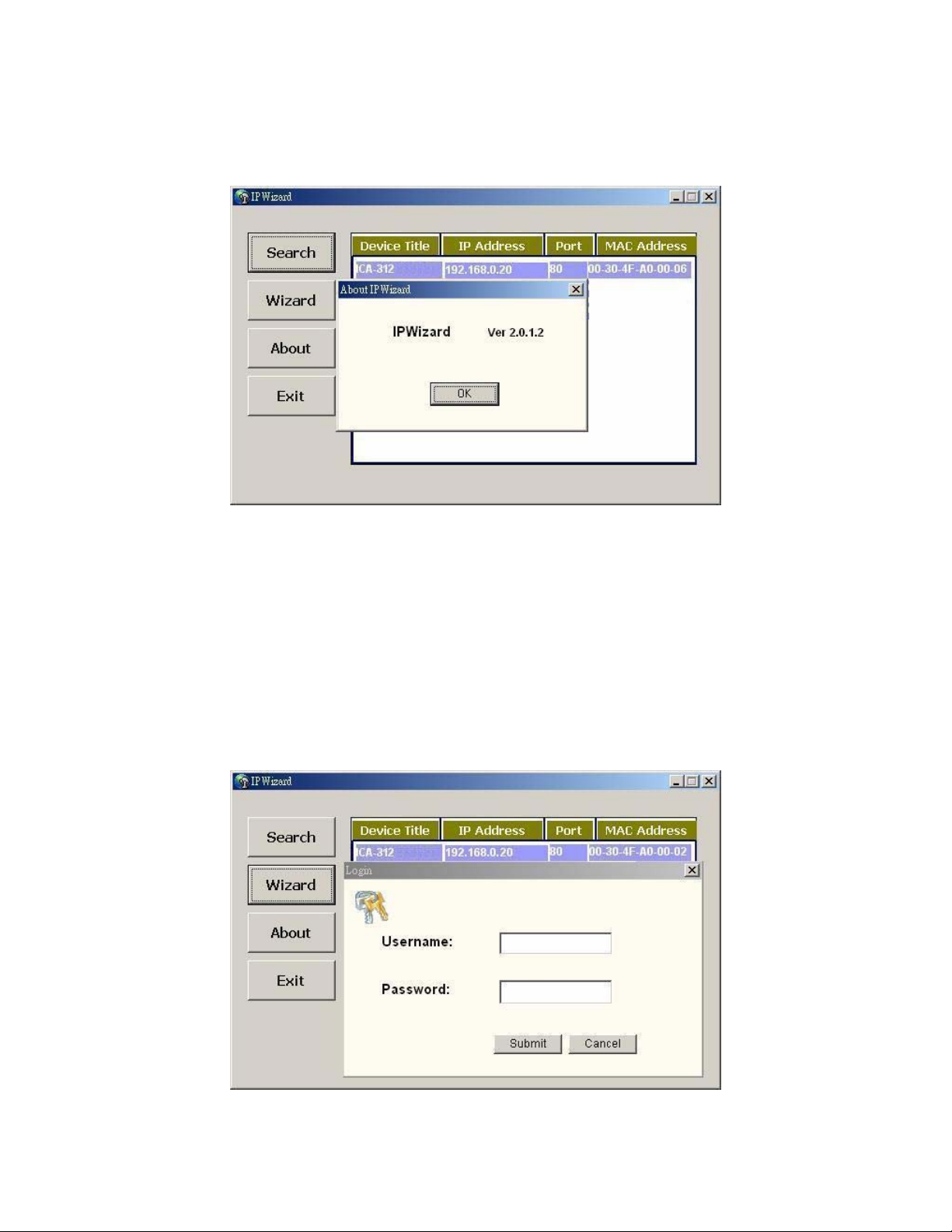
About Button:
When click “About” button, you will see the version information of IPWizard shown in the pop-up
dialog box.
Exit Button:
Click “Exit” button will close the IPWizard Program.
2.6 Configure With IPWizard
After pressing Installation Wizard, please key in Username and Pa ssword of the device when login
dialog box appears on the screen. You can login the setup page if authorized name and password
is correct. Default username/password for machine login: admin/<no password>
Note: If you open the case and reset to default, the warranty will be invalid, please write down the
username and password.
13/57
Page 15
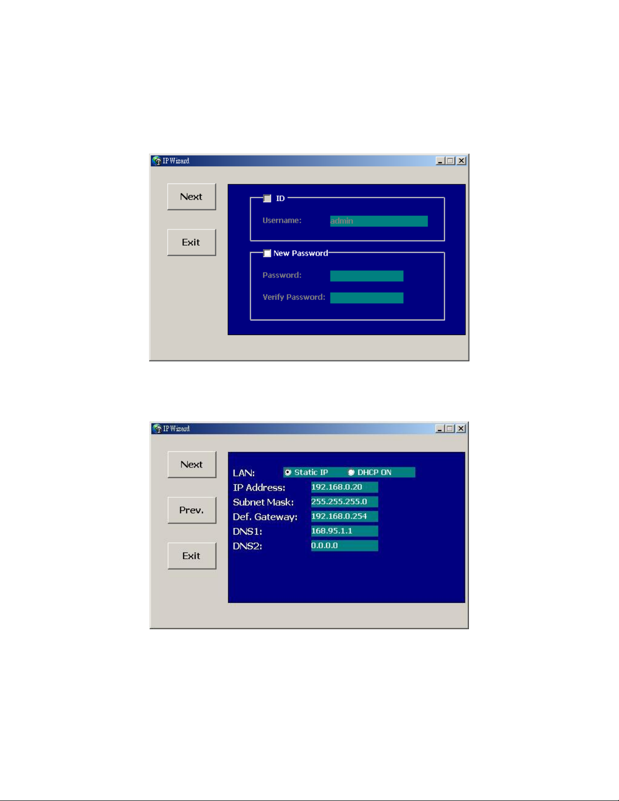
Wizard Page 1: Username and Password
This page is about the change of the authorized user name and password of the selected device. If
you don’t want to change them, please click “Next” to move to the next page. Press “Exit” button if
you don’t want to set up right now. If you want to change authorized name or password, you have
to check the box in front of ID or New Pas sword. Authorized Username should contain at least 5~
20 characters and New Password should contain at least 4~8 characters.
Wizard Page 2: LAN Setting
This page is about the select of Static IP or DHCP ON.
LAN: You can configure this ICA-312 to obtain its address automatically or manually assign. If
there is a DHCP server in your network environment and you select “DHCP ON”, ICA-312 can
automatically obtain an IP address. If you don’t have DHCP server or you want to use fixed IP
address, please select “Static IP” and fill in the following fields with proper parameters.
IP Address: IP address is a unique number for identifies this device on the WAN or LAN. These
14/57
Page 16
numbers are usually shown in groups separated by periods, for example: 192.168.0.200
Subnet Mask: Subnets allow network traffic between hosts to be separated based on the
network's configuration. In IP networking, traffic takes the form of packets. IP subnets advance
network security and performance to some level by organizing hosts into logical groups. Subnet
masks contain four bytes and usually appear in the same "dotted decimal" data. For example, a
very common subnet mask in its binary demonstration 11111111 11111111 11111111 00000000 will
usually be shown in the corresponding, more readable form as 255.255.255.0.
Def. Gateway: A gateway is a piece of software or hardware that passes information between
networks. You'll see this term most often when you either log in to an Internet site or when you're
transient email between different servers.
DNS1: When you send email or position a browser to an Internet domain such as xxxxx.com, the
domain name system translates the names into IP addresses. The term refers to two things: the
conventions for naming hosts and the way the names are control across the Internet.
DNS2: The same function as DNS1. It is optional, not necessary
Note: If no IP address is assigned after 30 seconds, the ICA-312 will work with its default IP
address 192.168.0.20. User may now open your web browser, and key in http://192.168.0.20
in
the address bar of your web browser to logon ICA-312’s web configuration page.
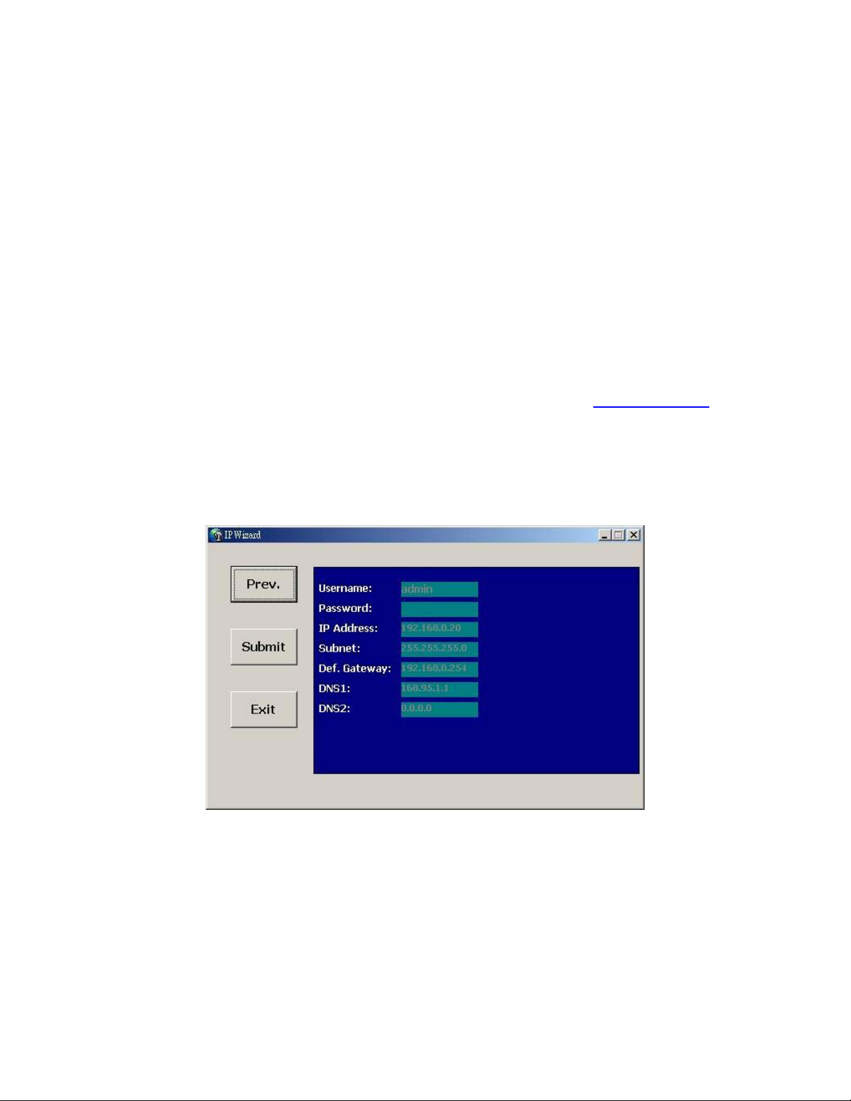
Wizard Page 3: Confirmation
This page shows the new configurations. If it is correct, please press “Submit” icon and the setting
information will be save to your ICA-312. Click on “Exit” to close this window.
15/57
Page 17
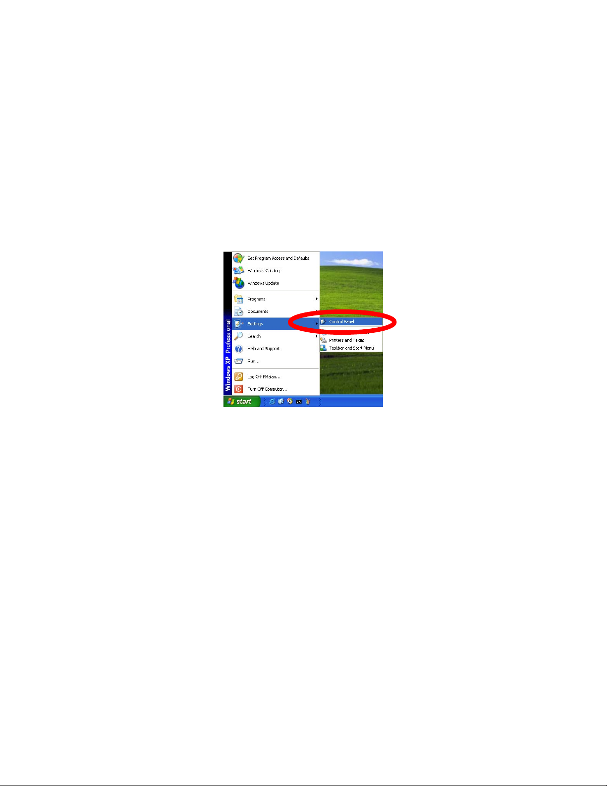
2.7 Using UPnP of Windows® XP™
UPnP™ is short for Universal Plug and Play, which is a networking architecture that provides
compatibility among networking equipment, software, and peripherals. This device is an UPnP
enabled device. If the operating system, Windows XP, of your PC is UPnP enabled, the device will
be very easy to configure. Use the following steps to enable UPnP settings only if your operating
system of PC is running Windows XP.
Note: Windows 2000 does not support UPnP feature.
Go to Start > Settings, and Click Control Panel
16/57
Page 18
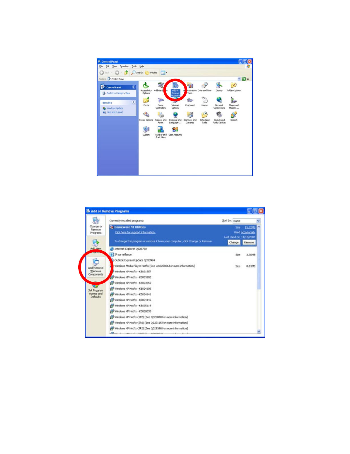
The “Control Panel” will display on the screen and double click Add or Remove Programs to
continue
The “Add or Remove Programs” will display on the screen and click Add/Remove Widows
Components to continue.
17/57
Page 19
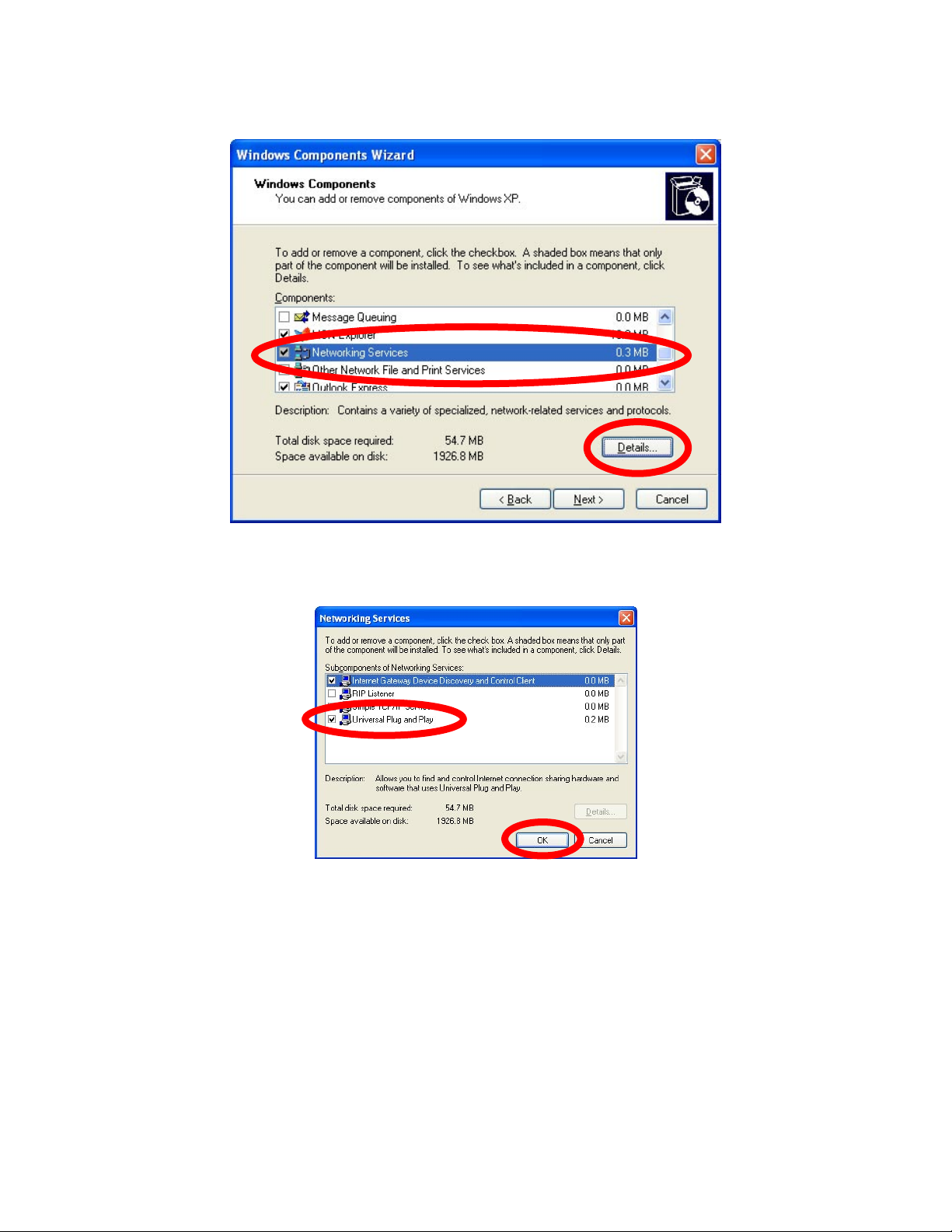
The following screen will appear, select Networking Services and click Details to continue.
The “Networking Services” will display on the screen, select Universal Plug and Play and click
OK to continue.
18/57
Page 20
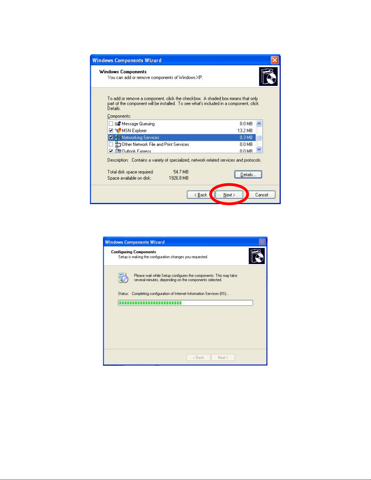
Please click Next to continue
The program will start installing the UPnP automatically. You will see the below pop-up screen,
please wait while Setup configures the components.
19/57
Page 21
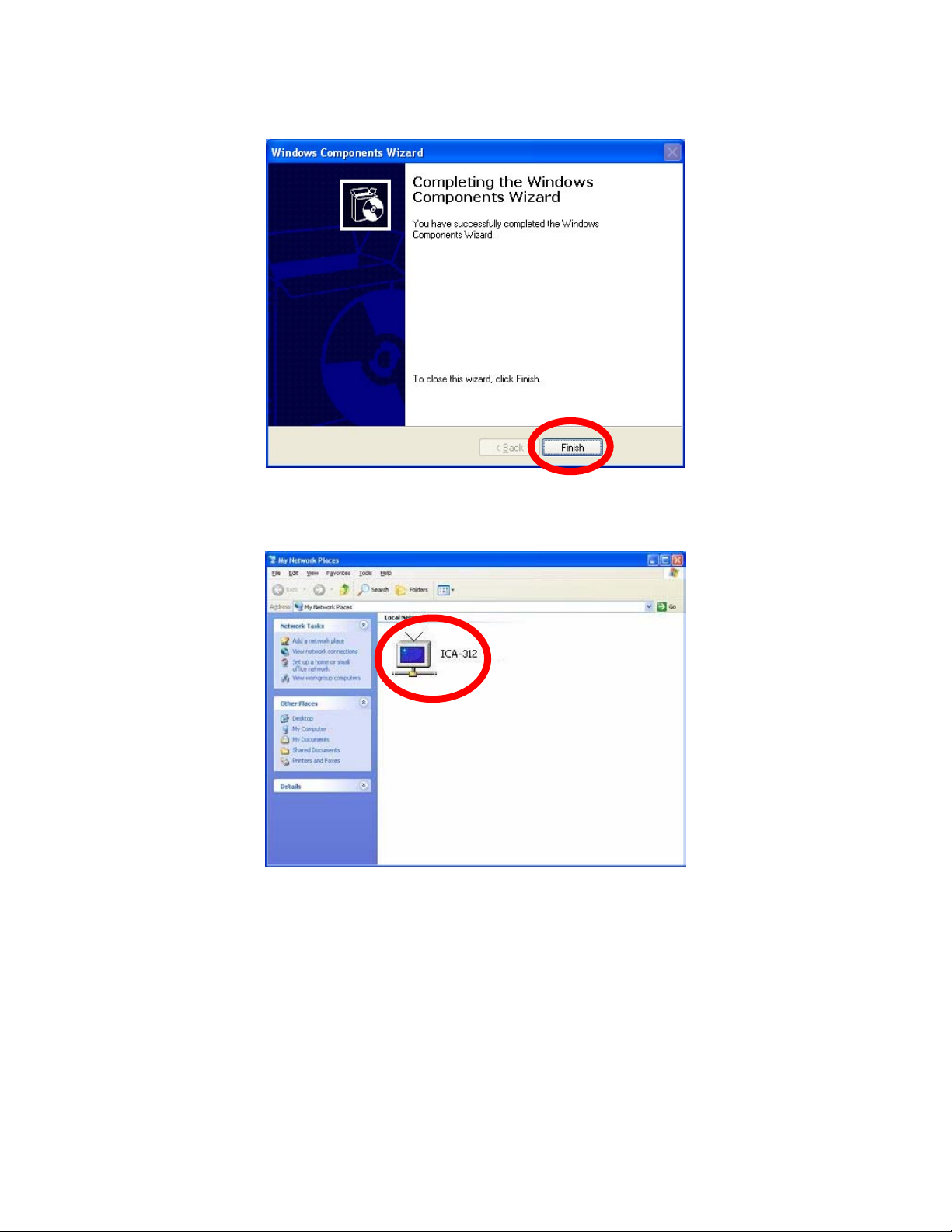
Please click Finish to complete the UPnP installation
Double-click My Network Places on the desktop, the “My Network Places” will display on the
screen and double-click the UPnP icon with ICA-312 to view your device in an internet browser.
2.8 Setup ActiveX to use the ICA-312
The ICA-312 web page communicates with the ICA-312 using an ActiveX control. The ActiveX
control must be downloaded from the ICA-312 and installed on your PC. Your Internet Explorer
security settings must allow for the web page to work correctly. To use the ICA-312, user must
setup his IE browser as follows:
From your IE browse Î ”Tools” Î ”Internet Options…” Î ”Security” ΔCustom Level…”, please
setup your “Settings” as follow.
20/57
Page 22
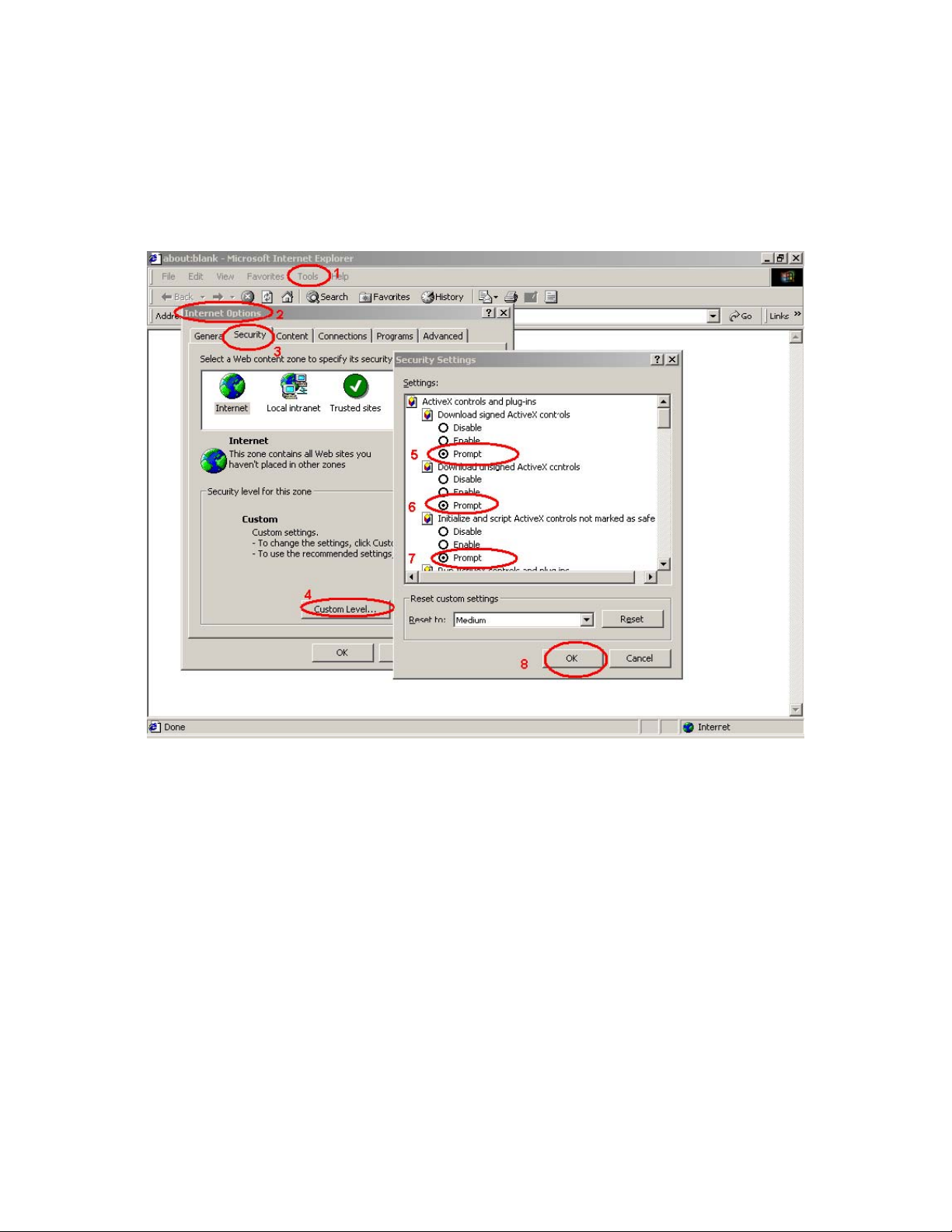
Set the first 3 items
• Download the signed A ctiveX co ntrols
• Download the unsigned ActiveX controls
• Initialize and script the ActiveX controls not masked as safe to Prompt
By now, you have finished your entire PC configuration for ICA-312.
21/57
Page 23
3. Web-based Management
This chapter provides setup details of the ICA-312’s Web-based Interface.
3.1 Introduction
The ICA-312 can be configured with your Web Browser. Before configure, please make sure
your PC is under the same IP segment with ICA-312.
3.2 Connecting to ICA-312
z Use the following procedure to establish a connection from your PC to the ICA-312.
z Once connected, you can add the ICA-312 to your Browser’s Favorites or Bookmarks.
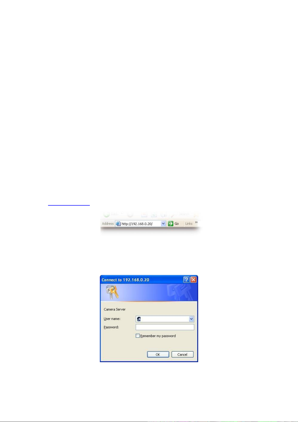
Start the web browser on the computer a nd type the IP addres s of the ICA-312. The Default IP:
“ http://192.168.0.20
The login window of ICA-312 will appear, Default login username/password is :
admin/ <no password>
“
Note: If the User name and Password have been changed with IPWizard, please enter the
new User name and Password here.
22/57
Page 24
Note: If you open the case and reset to default, the warranty will be invalid, please write down
the username and password.
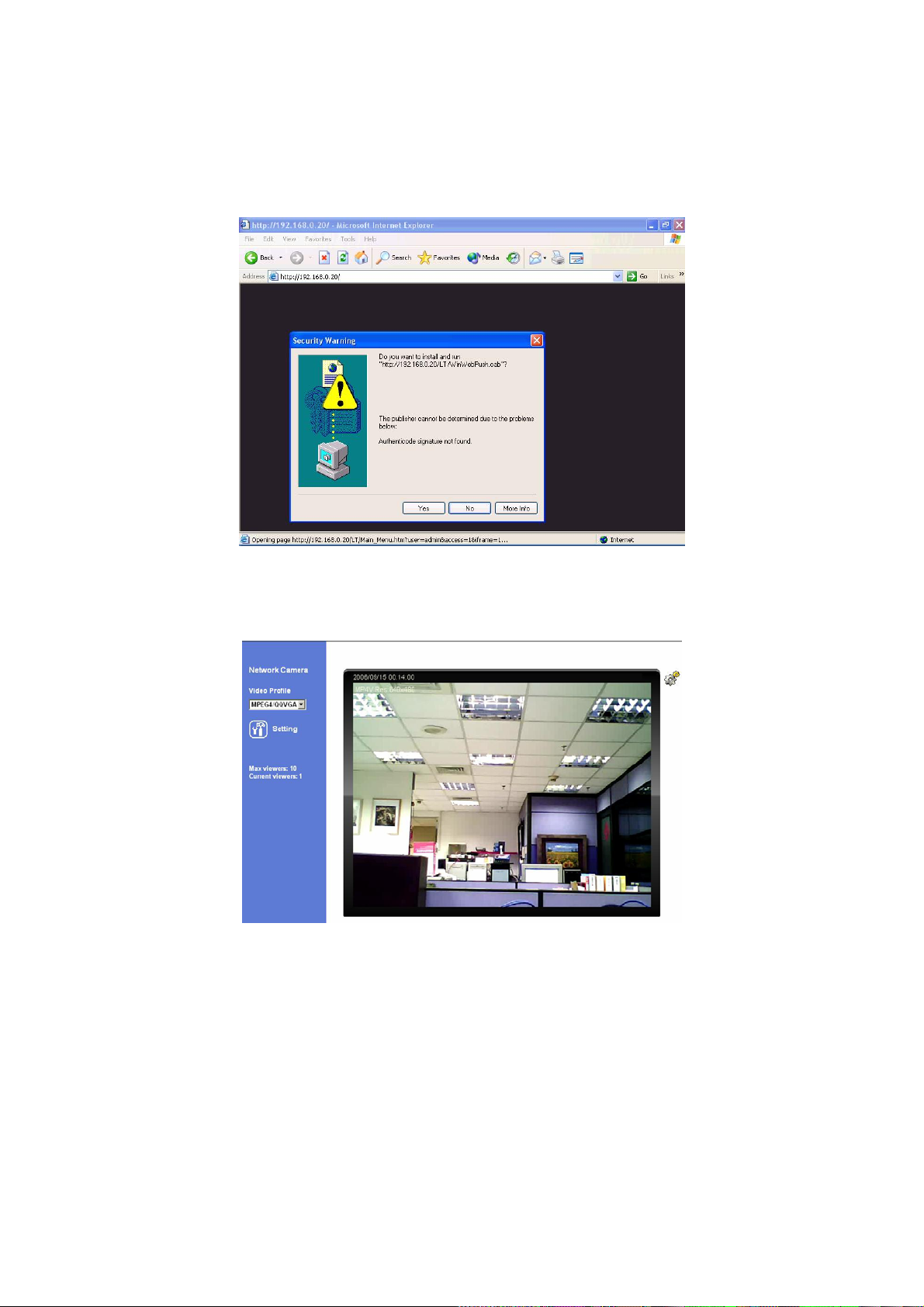
Web browser may display the “Security Warming” window, select “Yes” to install and run the
ActiveX control into your PC.
After the ActiveX control was installed and run, the first image will be displayed.
Note: If you log in the ICA-312 as an ordinary user, setting function will be not available. If you
log in the ICA-312 as the administrator, you can perform all the settings provided within the
device.
23/57
Page 25
3.3 Live View
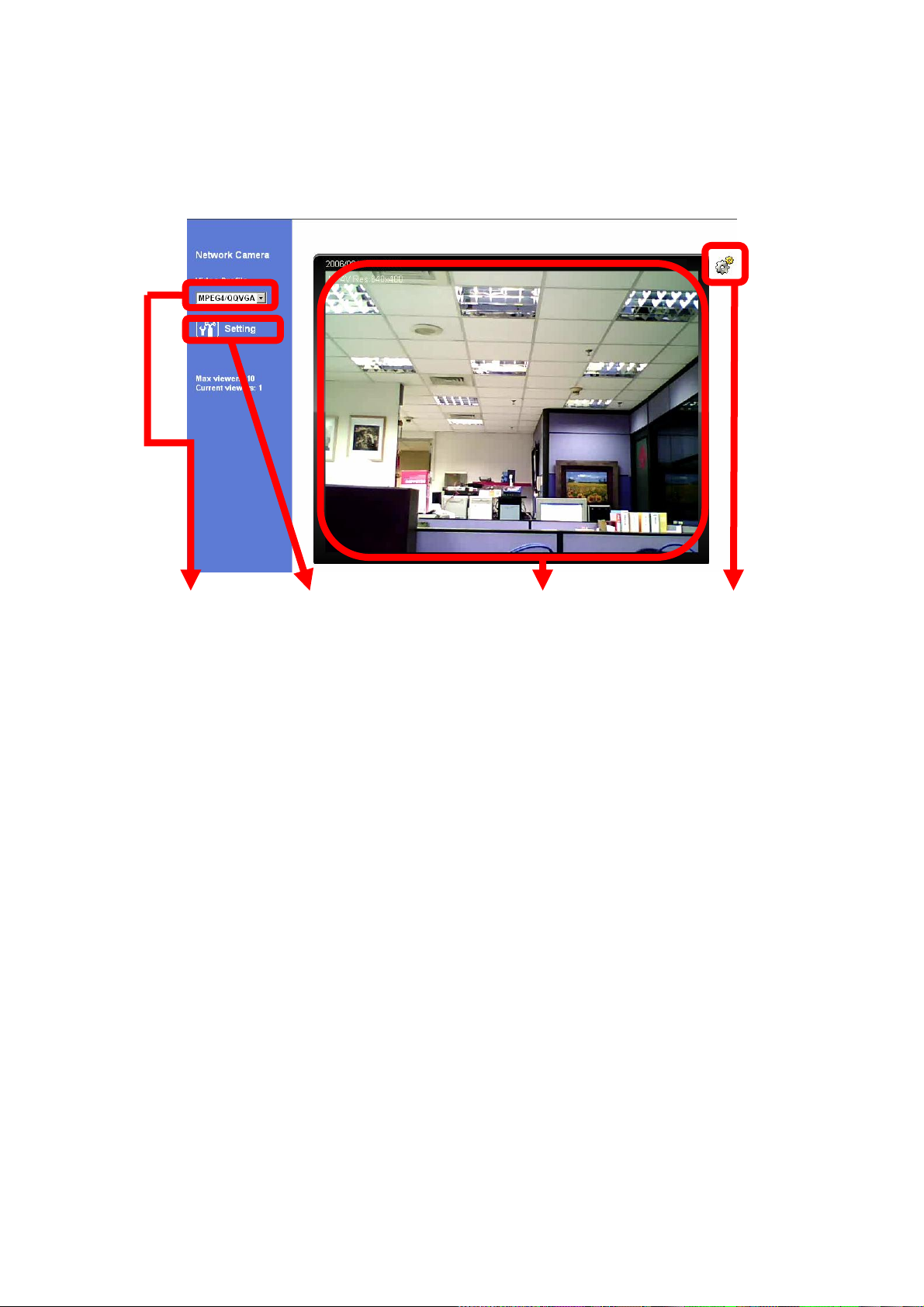
Start-up screen will be as follow no matter an ordinary users or an administrator.
Video Profile Setting Menu Monitor Image Section ActiveX Control
Monitor Image Section: The image shot by the ICA-312 is shown here. The date and time are
displayed at the top of the window.
Video Profile: The ICA-312 support multi-profile for both MEPG4 and M-JPEG simultaneously.
User can chose the proper and/or preferred profile here.
ActiveX Control: The plug-in ActiveX control supports a lot of functions by clicking the left
mouse button. Note that this feature only supports on the ActiveX control within Microsfoft®
Internet Explorer.
Setting Menu: This function is detail setting for ICA-312 that only available for user logged
into ICA-312 as administrator.
3.4 ActiveX Control
On the ActiveX control icon, click the LeftMouseButton, then a menu pop-up. This menu
provides features that are unique to the ActiveX control. These features include:
• “Digital Zoom”,
• “Record”, d”,
• “Snapshot”, • “Snapshot”,
• “Statistics”, • “Statistics”,
24/57
Page 26
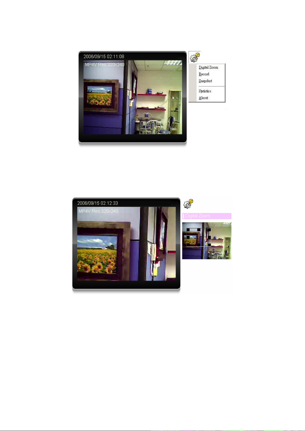
• “About”
3.4.1 Digital Zoom
Click Digital Zoom to active this function as above. User can drag or scale the box over the
video to adjust zoom ratio and position.
3.4.2 Record
Click Record to activate this function. Press Record button to start recording. The video file is
saved as ASF format into your local PC. While you want to stop it, pre ss Stop to stop recording.
Select Browser, the pop-up window to select the save path and file name prefix, select OK to
continue.
After stop recording, list the files, this file is named as Video_yyyymmddhhmmss.asf
The ASF files can be display by the standard Windows Media Player, but it needs the DixectX
9.0 or later version to be installed.
Note: Default save path is “C:\Documents and Settings\All user\Desktop
25/57
Page 27
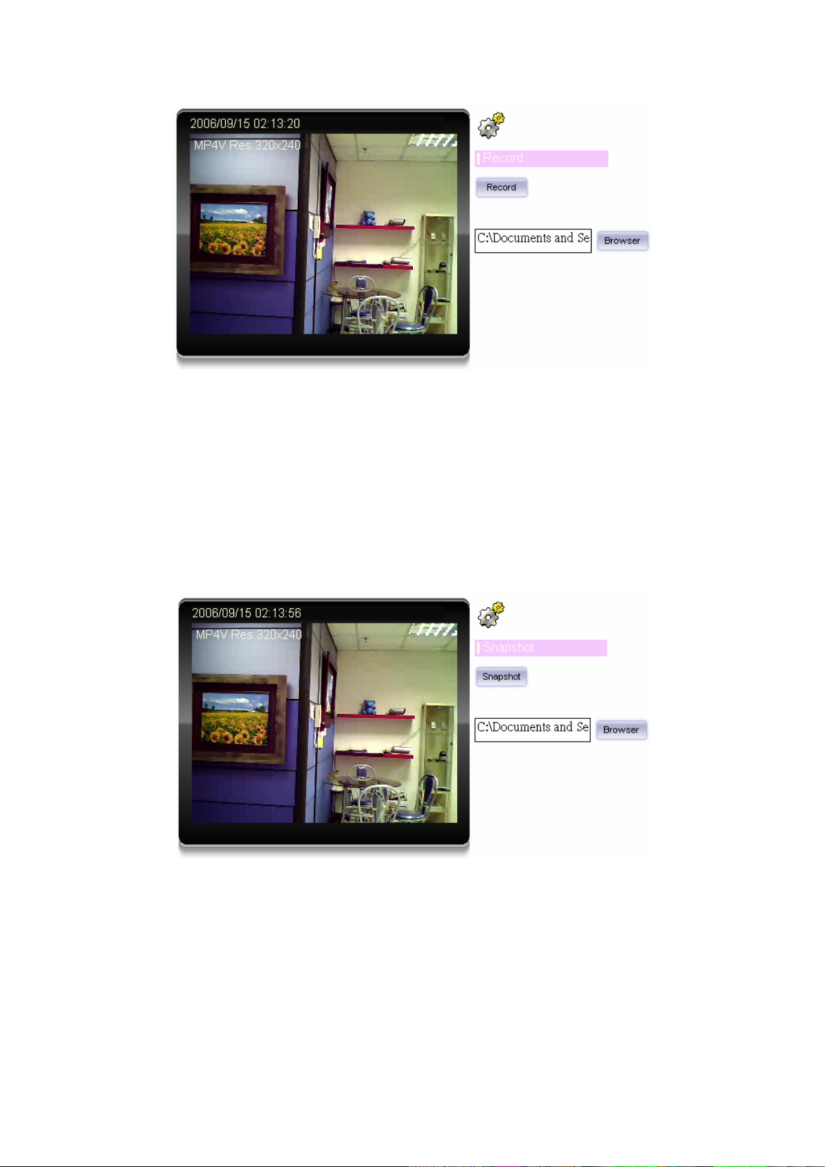
3.4.3 Snapshot
Click Snapshot to activate this function. Press Snapshot button to take a picture. The image
file is saved as JPEG format into your local PC. Select Browser, the pop-up window to select
the save path and file name prefix, select OK to continue.
If you like to retrieve the saved image, select the file to display the saved image by using any
one of graph editing tools.
Note: Default save path is “C:\Documents and Settings\All user\Desktop
3.4.4 Statistics
Click Statistics to activate this function. A window will be popup to show the statistics
information of the streaming status. Note that this information is the statistics between the
device and your local PC.
26/57
Page 28
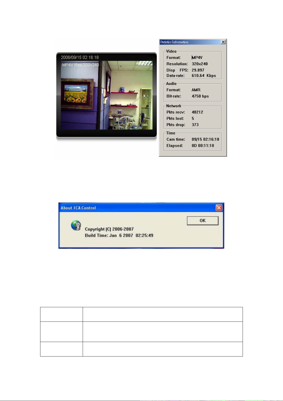
3.4.5 About
Click About to show the ActiveX information
3.5 System Setting
This function is only available for user logged into ICA-312 as administrator.
Click in each menu name to display its setting page.
Item Action
Network Configure Network settings such as DHCP, DDNS, 3GPP, PPPoE and
UPnP
Camera Adjust camera parameters
27/57
Page 29
System Configure system information, date & time, maintenance, and view
system log file.
Video Configure bit rate and frame rate of video profiles
User Setup user name, password and login privilege
E-Mail Setup E-Mail configuration
FTP This device is a client site and configure information to upload images to
server
Object detection Setup Object detection
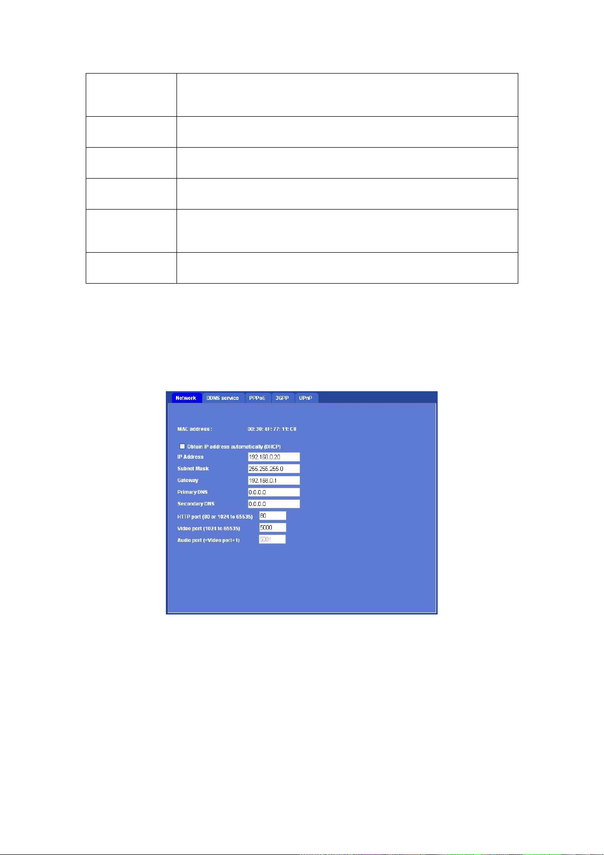
3.5.1 Network
Use this menu to configure the network to connect the device and the clients.
This section provides the menu of connecting the device through Ethernet cable.
MAC address: Display the Ethernet MAC address of the device. Note that user cannot
change it.
Obtain an IP address automatically (DHCP): DHCP: Stands for Dynamic Host Configuration
Protocol. Enable this checked box when a DHCP server is installed on the network to issue IP
address assignment. With this setting, the IP address is assigned automatically. If this device
cannot get an IP address within limited tries, the device will assign a default IP address,
192.168.0.20, by itself as the default IP address.
IP address, Subnet mask, Gateway, 1st DNS, 2nd DNS server: If you do not select Obtain
an IP address automatically, then you need to enter these network parameters by yourself.
28/57
Page 30

IP Address: This address is a unique numbers that identifies a computer or device on the
WAN or LAN. These numbers are usually shown in groups separated by periods, for example:
192.168.0.200
Subnet Mask: Subnets allow network traffic between hosts to be separated based on the
network's configuration. In IP networking, traf fic takes the form of packets. IP sub nets advance
network security and performance to some level by organizing hosts into logical groups.
Subnet masks contain four bytes and usually appear in the same "dotted decimal" data. For
example, a very common subnet mask in its binary demonstration 11111111 11111111 11111111
00000000 will usually be shown in the corresponding, more readabl e form as 255.255.255.0.
Gateway: A gateway is a piece of software or hardware that passes information between
networks. You'll see this term most often when you either log in to an Internet site or when
you're transient email between different servers.
Primary DNS: When you send email or position a browser to an Internet domain such as
xxxxx.com, the domain name system translates the names into IP addresses. The term refers
to two things: the conventions for naming hosts and the way the names are control across the
Internet.
Secondary DNS: The same function as DNS1. It is option not necessary
Note: need to reboot the device to take this setting effect.
HTTP Port: The device supports two HTTP ports. The first one is default port 80 and this port
is fixed. This port is very useful for Intranet usage. The second HTTP port is changeable.
Users could assign the second port number of http protocol, and the WAN users should follow
the port number to login. If the http port is not assigned as 80, users have to add the port
number in back of IP address. For example: http://192.168.0.20:80
If multiple devices are installed on the LAN and also required to be accessed from the WAN,
then the HTTP Port can be assigned as the virtual server port mapping to support multiple
devices.
Video Port: Specify the transmission port number of video stream. The default value is 5000.
User can specify a number between 1024 and 65535.
Audio Port: The Audio port value is equal to Video port plus one and it cannot be modified by
user manually. (The function is useless in this model)
When the configuration is finish, please click “OK” to save and enable the setting.
.
3.5.2 DDNS server
DDNS: Stands for Dynamic Domain Name Server
The device supports DDNS. If your device is connected to xDSL directly, you might need this
feature. However, if your device is behind a NAT router, you will not need to enable this feature.
Because DDNS allows the device to use an easier way to remember naming format rather
than an IP address. The name of the domain is like the name of a person, and the IP address
is like his phone number. On the Internet we have IP numbers for e ach host (computer, server,
router, and so on), and we replace these IP numbers to easy remember names, which are
organized into the domain name. As to xDSL environment, most of the users will use dynamic
IP addresses. If users want to set up a web or a FTP server, then the Dynamic Domain Name
Server is necessary. For more DDNS configuration, please consult your dealer.
Your Internet Service Provider (ISP) provides you at least one IP address which you use to
29/57
Page 31
connect to the Internet. The address you get may be static, meaning it never changes, or
dynamic, meaning it’s likely to change periodically. Just how often it changes, depends on your
ISP. A dynamic IP address complicates remote access since you may not know what your
current WAN IP address is when you want to access your network over the Internet. The
solution to the dynamic IP address problem comes in the form of a dynamic DNS service.
The Internet uses DNS servers to lookup domain names and translates them into IP
addresses. Domain names are just easy to remember aliases for IP addresses. A dynamic
DNS service is unique because it provides a means of updating your IP address so that your
listing will remain current when your IP address changes. There are several excellent DDNS
services available on the Internet and best of all they’re free to use. One such service you can
use is www.DynDNS.org. You’ll need to register with the service and set up the domain name
of your choice to begin using it. Please refer to the home page of the service for detailed
instructions or refer to Appendix E for more information.
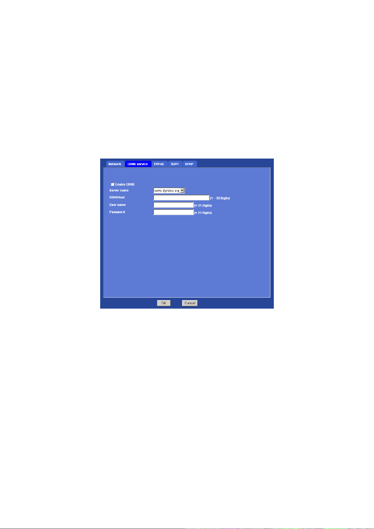
Enable DDNS: To enable or disable the DDNS service here.
Server name: Choose the built-in DDNS server.
DDNS Host: The domain name is applied of this device.
User name: The user name is used to log into DDNS.
Password: The password is used to log into DDNS.
3.5.3 PPPoE
PPPoE: Stands for Point to Point Protocol over Ethernet
A standard builds on Ethernet and Point-to-Point network protocol. It allows ICA-312 connect
to Internet with xDSL or cable connection, it can dial up your ISP and get a dynamic IP address.
For more PPPoE and Internet configuration, please consult your ISP.
It can directly connect to the xDSL, however, it should be setup on a LAN environment to
30/57
Page 32
program the PPPoE information first, and then connect to the xDSL modem. Power on again,
then the device will dial on to the ISP connect to the WA N through the xDSL modem.
The procedures are
• Connect to a LAN by DHCP or Fixed IP
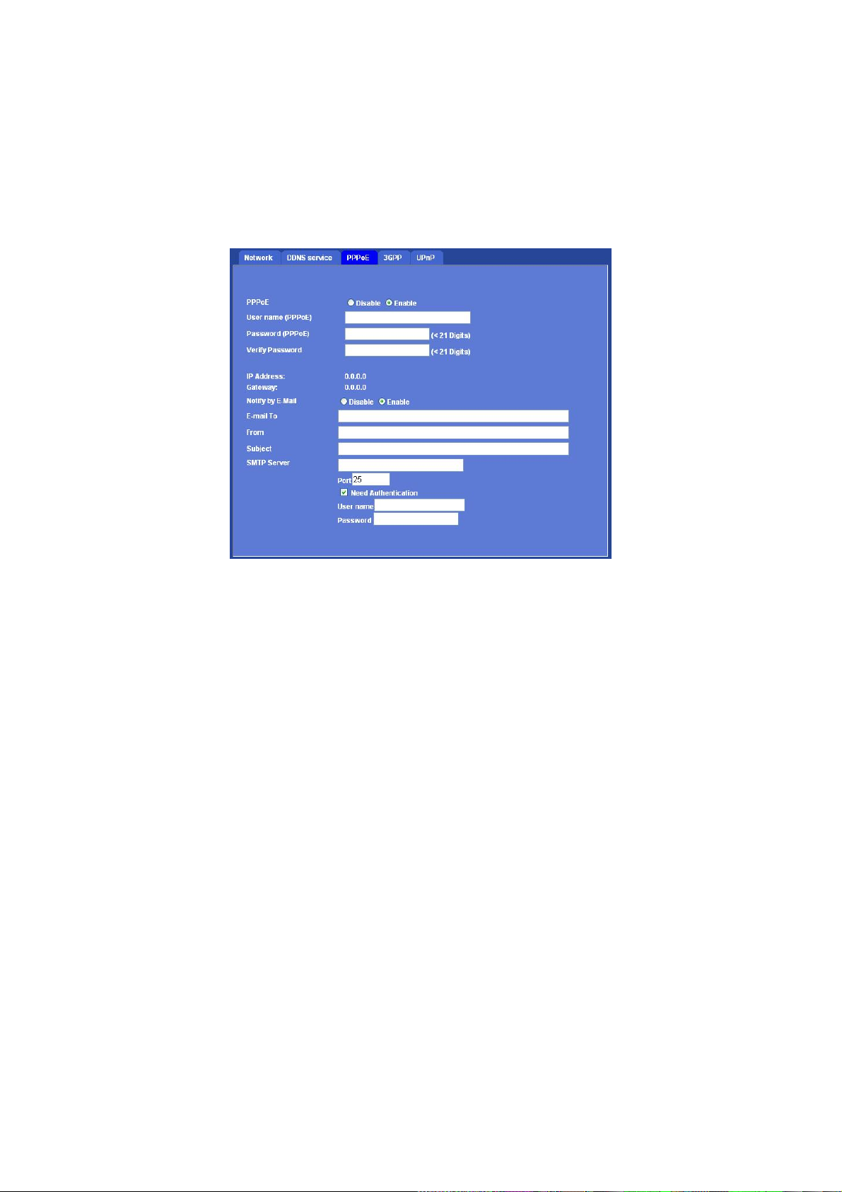
• Access the device, enter Setting Î Network Î PPPoE as below
Enable PPPoE: To enable or disable the PPPoE service here.
User name (PPPoE): Ty pe the user name for the PPPoE service which is provided by ISP.
Password (PPPoE): Type the password for the PPPoE service which is provided by ISP.
IP Address / Gateway: It will display IP address and gateway that ICA-312 gets a dynamic IP
from ISP, when ICA-312 each dials up success.
Notify by E-Mail: If enable this function, then the “SMTP Server” and “E-mail To” field need to
be filled.
E-mail To: Type the receiver’s e-mail address. This address is used for replay mail.
From: Type the sender’s E-mail address.
Subject: T y pe the server name of SMTP server.
Port: Set port number of SMTP service.
Need Authentication: If the mail server needs authentication, then choose the option “On”.
Also the password information needs to be inputted.
User name: Type the user name for the SMTP server.
Password: Type the password for the SMTP server.
31/57
Page 33
3.5.4 3GPP
The device is 3GPP compatible by default. To view live video over 3GPP:
• Contact your cell phone provider and make sure that 3GPP service is available and the
configuration is correct for your cell phone.
• Check that the device has a completely public IP address, i.e. no ports blocked by a
firewall. It is highly recommended that you have a fixed and public IP address.
• In Setting Î Video Î MP4/QQVGA Î Bit rate, set the maximum bit rate to 128 k bit/s.
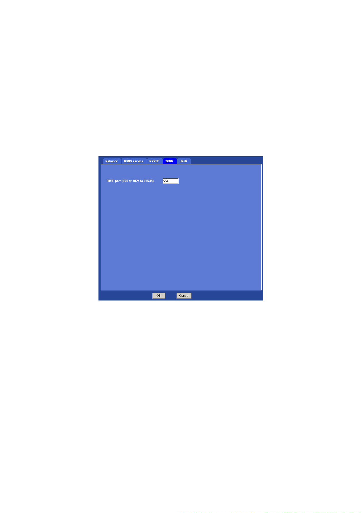
RTSP port: Choose the RTSP port. The default value is 554.
RTSP: Sands for Real Time Streaming Protocol
Mobile Phone Dialing procedure:
Step 1: Contact your cell phone provider and make sure that 3GPP service is available.
Step 2: Enable “internet access” function on your mobile phone. Some telecom will
automatically download the setup profile to your mobile phone; some telecom need
you call the service center to enable the internet access function
Step 3: Choose a verified video player (ex. PacketVideo)
Step 4: Open the video player. Base on your requirement, type either URL address:
rtsp://host:554/avN for both audio and video tracks.
rtsp://host:554/videoN for video track only.
rtsp://host:554/audio for audio track only.
Note: Where host is the host name or IP address of the ICA-312, and N is the number of the
profile (1-=MPEG4 VGA, 2=MPEG4 QVGA, 3=MPEG4 QQVGA) for the video stream. 3 is
recommended.
32/57
Page 34
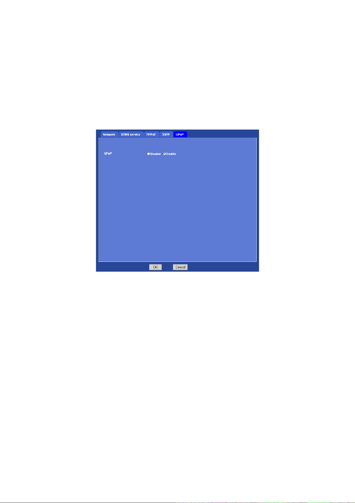
3.5.5 UPnP
UPnP (Universal Plug and Play) which is a networking architecture that provides compatibility
among networking equipment, software, and peripherals. This device is an UPnP enabled
ICA-312. If your operating system is UPnP enabled, the device will automatically be detected
and a new icon will be added to “My Network Places.” If you do not want to use the UPnP
functionality, it can be disabled.
Enable UPnP discovery: To enable or disable the UPnP discovery service here.
33/57
Page 35
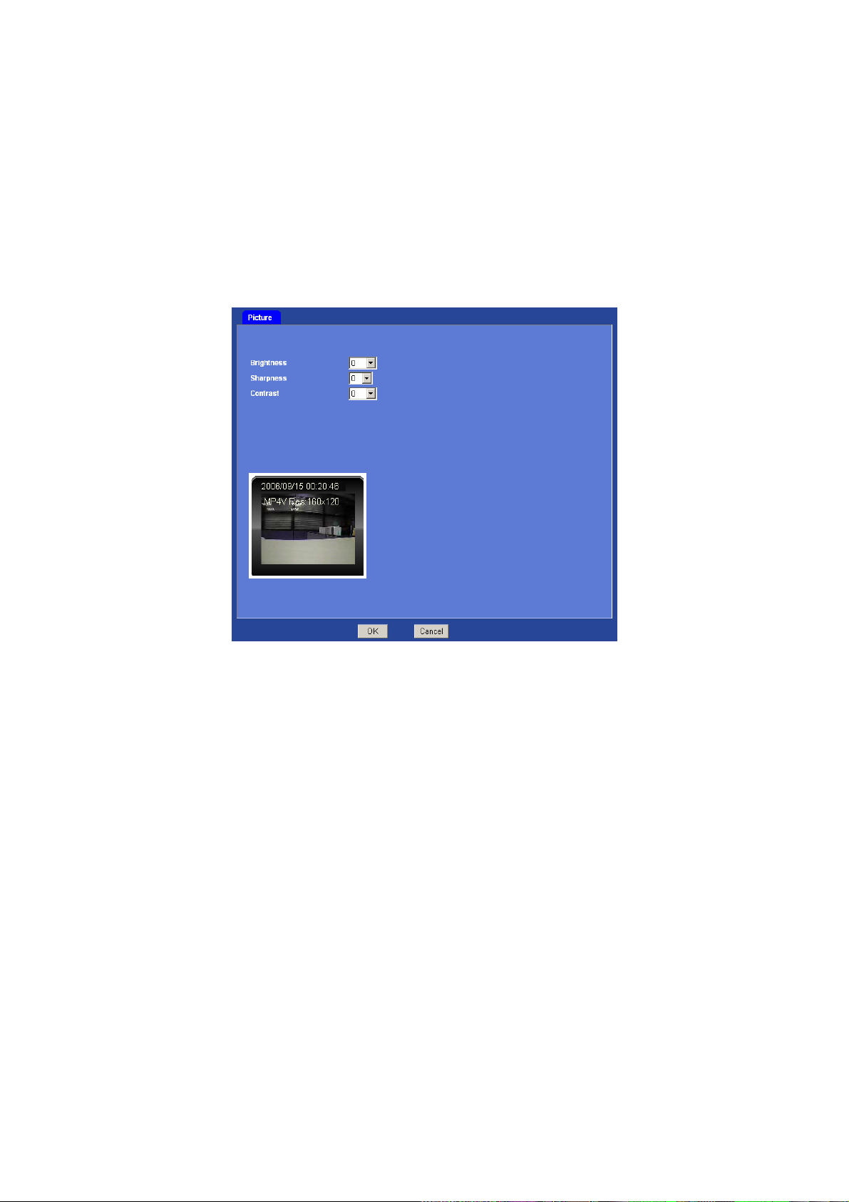
3.6 Camera
You can adjust the camera view quality in this menu.
Picture
Brightness: Large value will brighten camera.
Sharpness: Large value will sharpen camera.
Contrast: Large value will contrast camera heavily.
3.7 System
Use this menu to perform the principal settings of ICA-312.
3.7.1 Date & Time
Y ou ca n setup the time setting of ICA-312, make it synchroni zed with PC or remote NTP server.
Also, you may select the correct time zone of your country.
34/57
Page 36
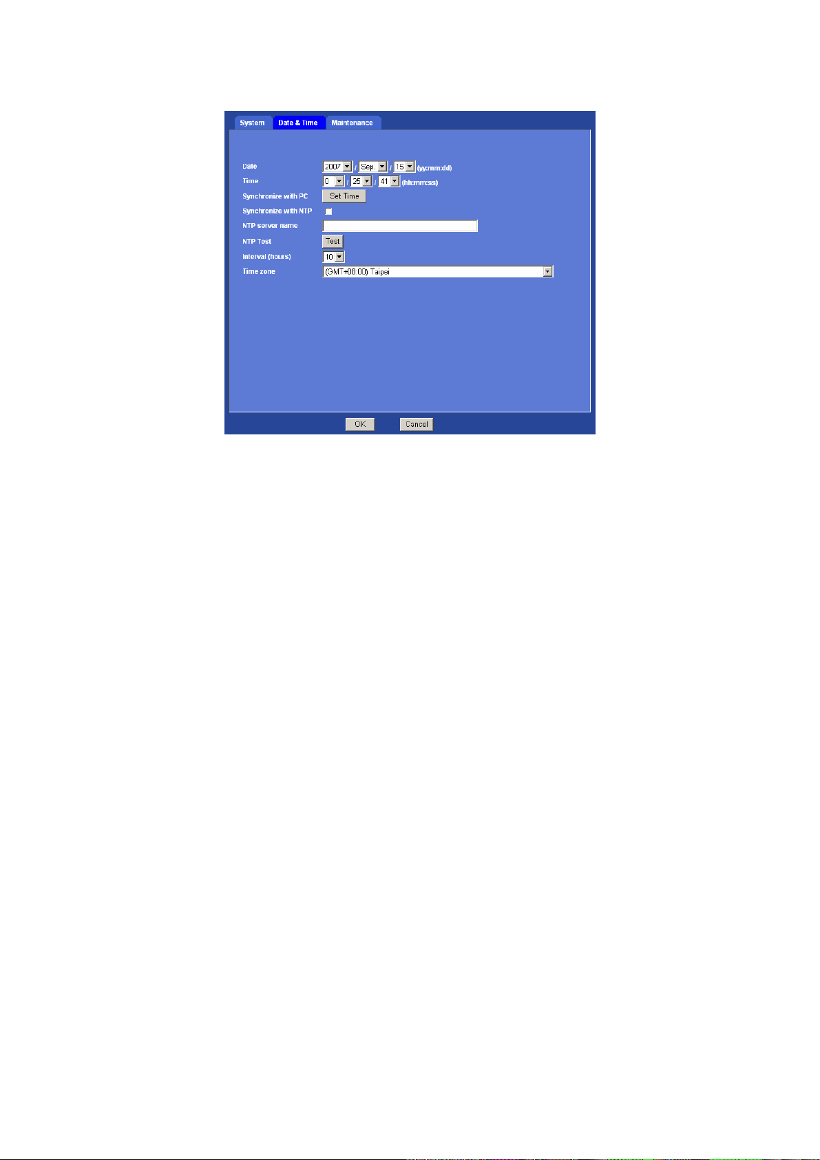
Date: Displays the date of the device.
Time: Displays the date of the device.
Synchronize with PC: Press “Set Time” button to do the time synchronization with PC time.
Synchronize with NTP: Select if you want to synchronize the date and time with NTP server
(Network Time Protocol). Please set the NTP server name and the Interval.
NTP server name: Type the host name or IP address of the NTP serve r.
Interval: Select an interval between 1 and 24 hours at which you want to adjust the device’s
time referring to NTP server.
Time zone: Set the time difference from Greenwich Mean Time in the area where the device is
installed.
35/57
Page 37

3.7.2 Maintenance
Factory Default: Reset this device to factory default settings. Note that click this button will
reset all device parameters to the factory settings.
Firmware upgrade: The device supports new firmware upgrade.
Unzip this firmware file to binary file and store it into your PC. Then follow the steps as bello ws
carefully:
1. Close all other application programs which are not necessary for firmware update.
2. Make sure that only you access this device at this moment
3. Disable Motion Detection function.
4. Select “Firmware name”
5. Select the Firmware binary file. (Note that it must make sure that the Firmware only applies
to this device, once update, it will be burned into FLASH ROM of system.)
6. Once the firmware file was selected, select “Upgrade”.
7. The upgrade progress information will be displayed on the screen.
8. A message will be shown while the firmware upgraded. Once the upgrading
process completed, the device will reboot the system automatically.
9. Please wait for 80 seconds, and then you can use IPWizard to search the device again.
Warning!!! The do wnload firm ware procedure cannot be interr upted. If the power and/or
network connection are broken during the download procedure, it might possibly cause
serious damage to the device.
Please be aware that you should not turn off the power during updating the firmware
and wait for finish message.
Furthermore, do not try to upgrade new firmware if it’s not necessary.
36/57
Page 38
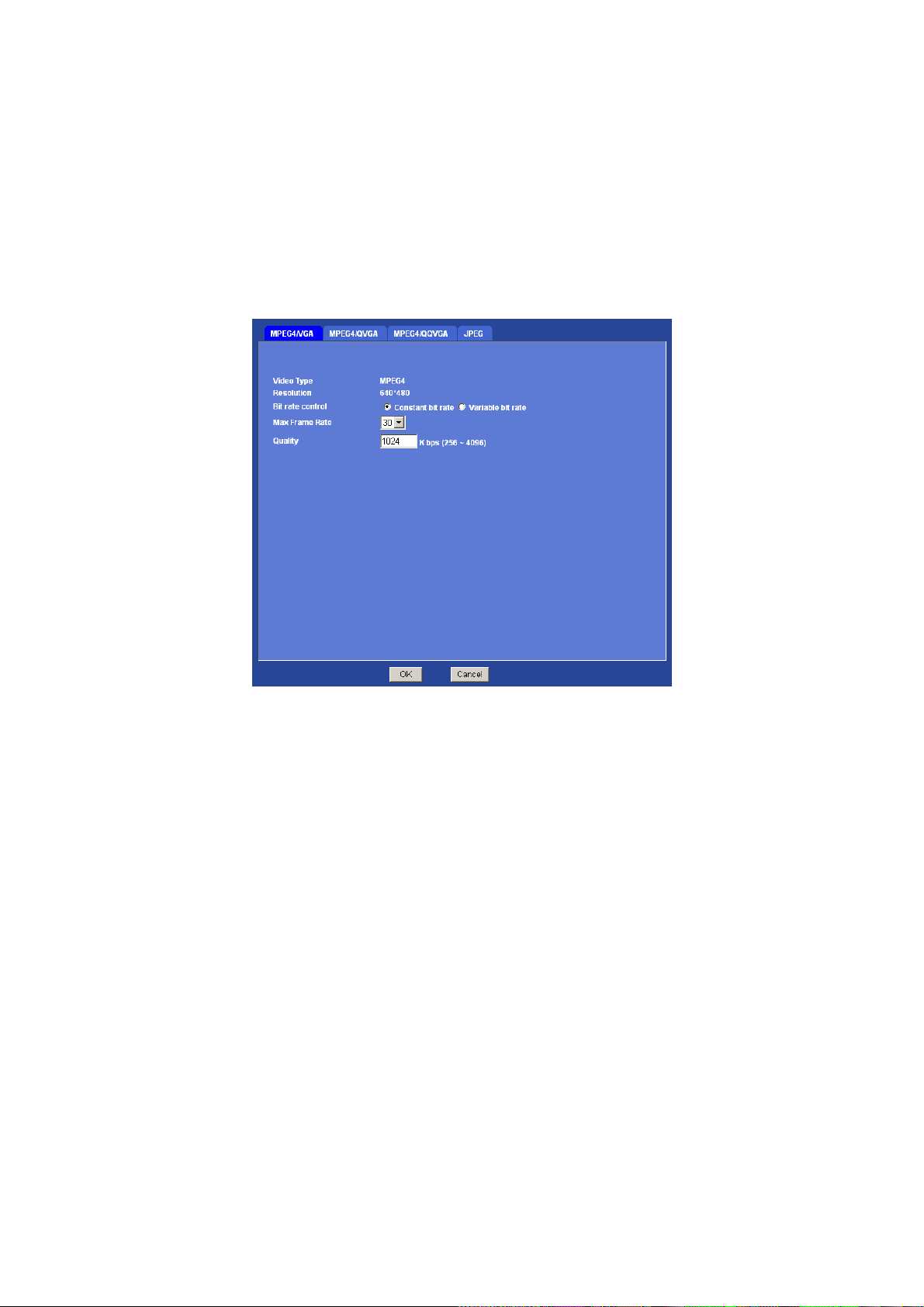
3.8 Video
This device provides 4 video profiles as below to support different request to each client
simultaneously. Each user can choose his preferred video profile as his request indep endently.
3.8.1 MPEG4/VGA
Video Type: It’s MPEG4 mode in this profile.
Resolution: It’s VGA mode (640x480) in this profile.
Bit rate control: Defines the rate control method of this profile. There are two options:
Constant Bit Rate (CBR) or Variable Bit Rate (VBR). For CBR, the idea bit rate is between
256kbps and 4096kbps. User can set the desired bit rate to match the limitation of bandwidth.
For VBR, user should choose the quantization level to set the video quality rather than bit rate.
Max Frame Rate: Defines the targeted frame rate of this profile. For example, set the frame
rate to 15 fps, then the image will be updated for 15 frames per second. User can set the
desired max frame rate versus video quality under the limited bandwidth.
Quality or Quantization level: For CBR mode, user should define the bit rate of this profile.
For VBR mode, user should define the quantization level of this profile.
37/57
Page 39
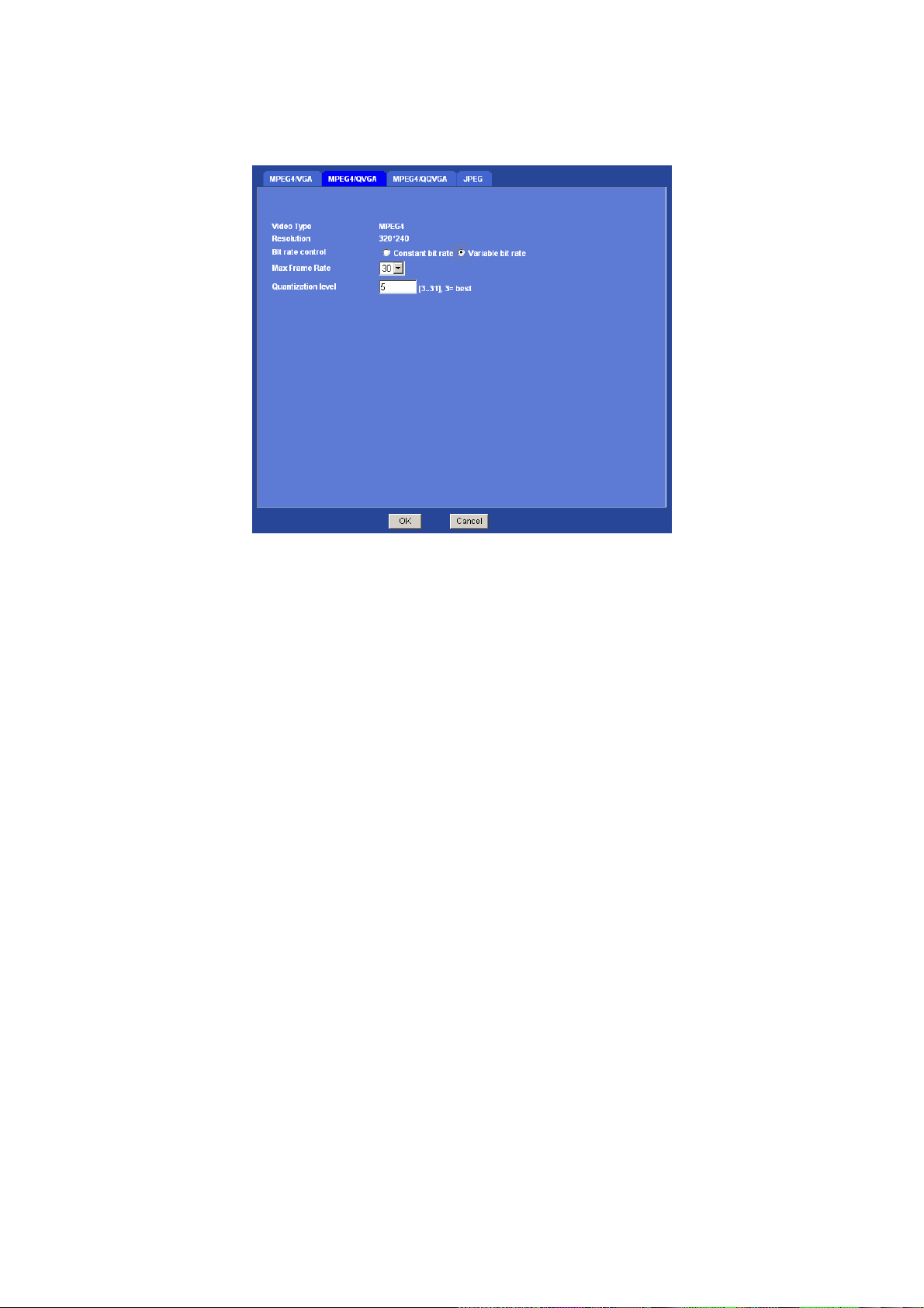
3.8.2 MPEG4/QVGA
Video Type: It’s MPEG4 mode in this profile.
Resolution: It’s QVGA mode (320x240) in this profile.
Bit rate control: Defines the rate control method of this profile. There are two options:
Constant Bit Rate (CBR) or Variable Bit Rate (VBR). For CBR, the idea bit rate is between
256kbps and 4096kbps. User can set the desired bit rate to match the limitation of bandwidth.
For VBR, user should choose the quantization level to set the video quality rather than bit rate.
Max Frame Rate: Defines the targeted frame rate of this profile. For example, set the frame
rate to 15 fps, then the image will be updated for 15 frames per second. User can set the
desired max frame rate versus video quality under the limited bandwidth.
Quality or Quantization level: For CBR mode, user should define the bit rate of this profile.
For VBR mode, user should define the quantization level of this profile.
38/57
Page 40
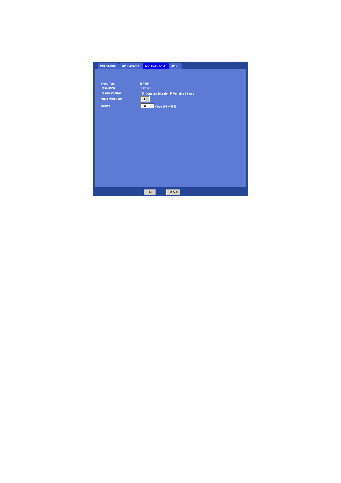
3.8.3 MPEG4/QQVGA
Video Type: It’s MPEG4 mode in this profile.
Resolution: It’s QQVGA mode (160x120) in this profile.
Bit rate control: Defines the rate control method of this profile. There are two options:
Constant Bit Rate (CBR) or Variable Bit Rate (VBR). For CBR, the idea bit rate is between
64kbps and 384kbps. User can set the desired bit rate to match the limitation of bandwidth. For
VBR, user should choose the quantization level to set the video quality rather than bit rate.
Max Frame Rate: Defines the targeted frame rate of this profile. For example, set the frame
rate to 15 fps, then the image will be updated for 15 frames per second. User can set the
desired max frame rate versus video quality under the limited bandwidth.
Quality or Quantization level: For CBR mode, user should define the bit rate of this profile.
For VBR mode, user should define the quantization level of this profile.
39/57
Page 41

3.8.4 JPEG/QVGA
Video Type: It’s JPEG mode in this profile.
Resolution: User can select VGA, QVGA, or QQVGA mode as the resolution of this JPEG
profile.
Quality: This profile provides 5 quality levels: Best, Better, Normal, Low, and Lowest in which
Best: Video is the best but need more bandwidth to transmit image
Lowest: Video is much worse but the bandwidth requirement is also lower.
Frame rate: Defines the targeted frame rate of this profile. For example, set the frame rate to
15 fps, then the image will be updated for 15 frames per second. User can set the desired max
frame rate versus video quality under the limited bandwidth.
40/57
Page 42
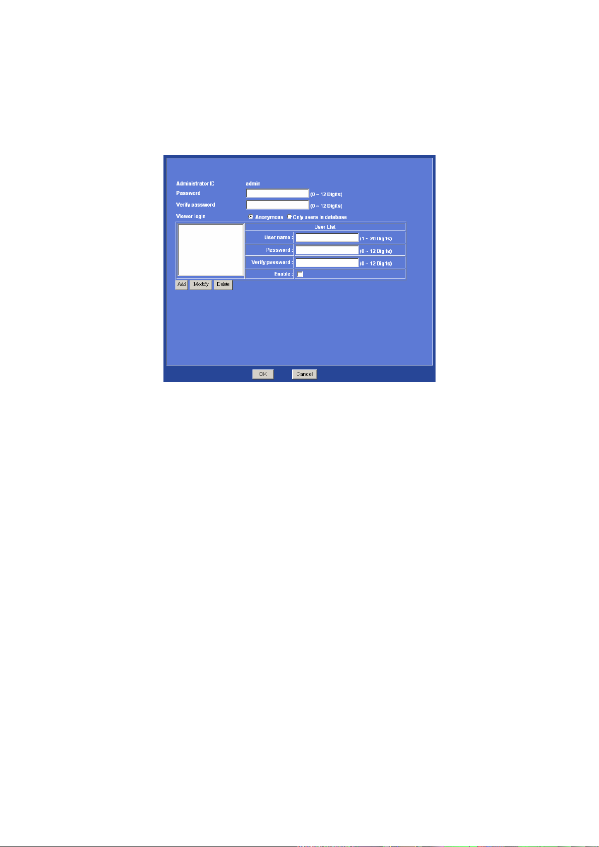
3.9 User
Use this menu to set the user names and password of the Administrator and up to 10 users,
and access right of each user.
Administrator level has authority to setup and modify all settings of ICA-312, thus please keep
this account for higher security.
Administrator ID: The username of “Administrator” is fixed as “ad m in”
Password: Enter the administrator’s new password here.
Verify Password: Please enter the administrator’s new password here again to confirm.
Note: If you open the case and reset to default, the warranty will be invalid, please write down
the username and password.
Anonymous: Choose this to enable anonymous user login.
Only users in database: Choose this to disable ano nymous u se r login.
General user level only has authority of video previewing, thus it cannot modify any setting of
ICA-312.
User name: Enter the user’s new account here which you want.
Password: Enter the user’s new password here.
Verify Password: Please enter the user’s new password here again to confirm.
Enable: Select if you want to enable user account.
41/57
Page 43
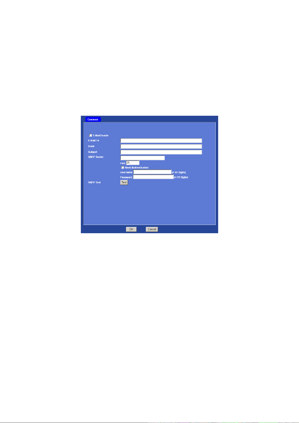
3.10 E-Mail
Using E-Mail function, user can send an e-mail with attached image file that has been shot
triggered with an external sensor or the built-in object detection function. The image file also
can be sent periodically.
Common
You may setup SMTP mail parameters for future event-message receiving such as object
detected or sensor activated.
E-Mail Enable: To enable or disable E-Mail function.
E-mail to: Type the receiver’s e-mail address. Note: you can specify multiple recipient email
addresses at the time.
From: Type the sender’s E-mail address. This address is used for reply e-mails.
Subject: Type the subject/title of the e-mail.
SMTP Server: Type the SMTP server name or the IP address of the SMTP server.
Port: Set port number of SMTP service.
Need Authentication: Select the authentication required when you send an e-mail.
On: if authentication is required when an e-mail is sent.
Off: if no authentication is required when an e-mail is sent.
User name: Type the user name for the SMTP server if Authentication is On.
Password: Type the password for the SMTP server if Authentication is On.
SMTP Test: Send a test mail to mail server to check this account is available or not.
3.11 FTP
Use this menu to set up for capturing and sending still images to an FTP server. Using FTP
42/57
Page 44
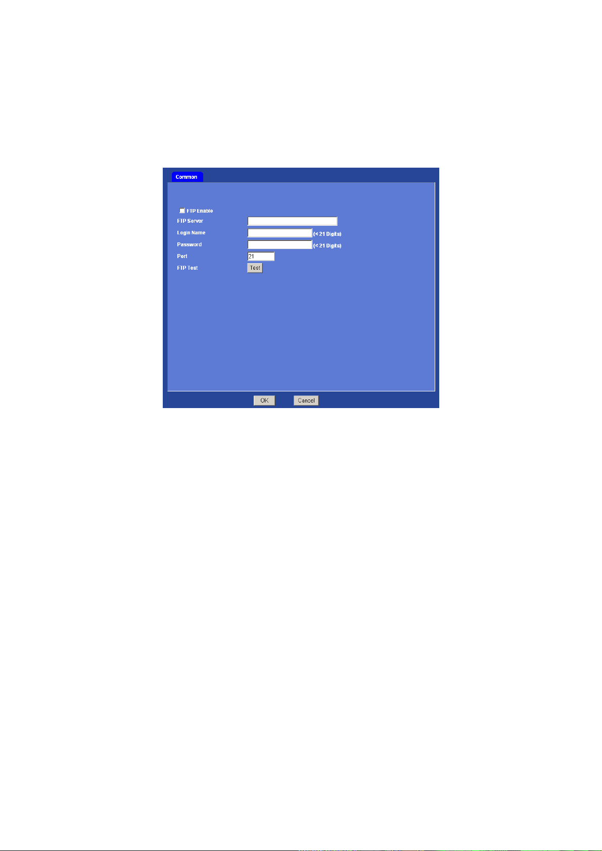
client function, user can send an image that has been shot linked with the built-in object
detection or external sensor input to an FTP server. The image file also can be sent
periodically.
Common
FTP Enable: To enable or disable the FTP function.
FTP Server: Type the server name or the IP address of the FTP server.
Login name: Type the user name for the FTP server.
Password: Type the password for the FTP server.
Port: Set port number of FTP service.
FTP Test: Check the FTP server whether this account is available or not.
3.12 Object detection
Using this menu, user can set the conditions to activate the built-in “Motion detection” and
“Object tracking” functions.
Motion detection
Use this menu to specify motion detection window 1 to window 4 and set the conditions for
detection while observing a captured image.
43/57
Page 45
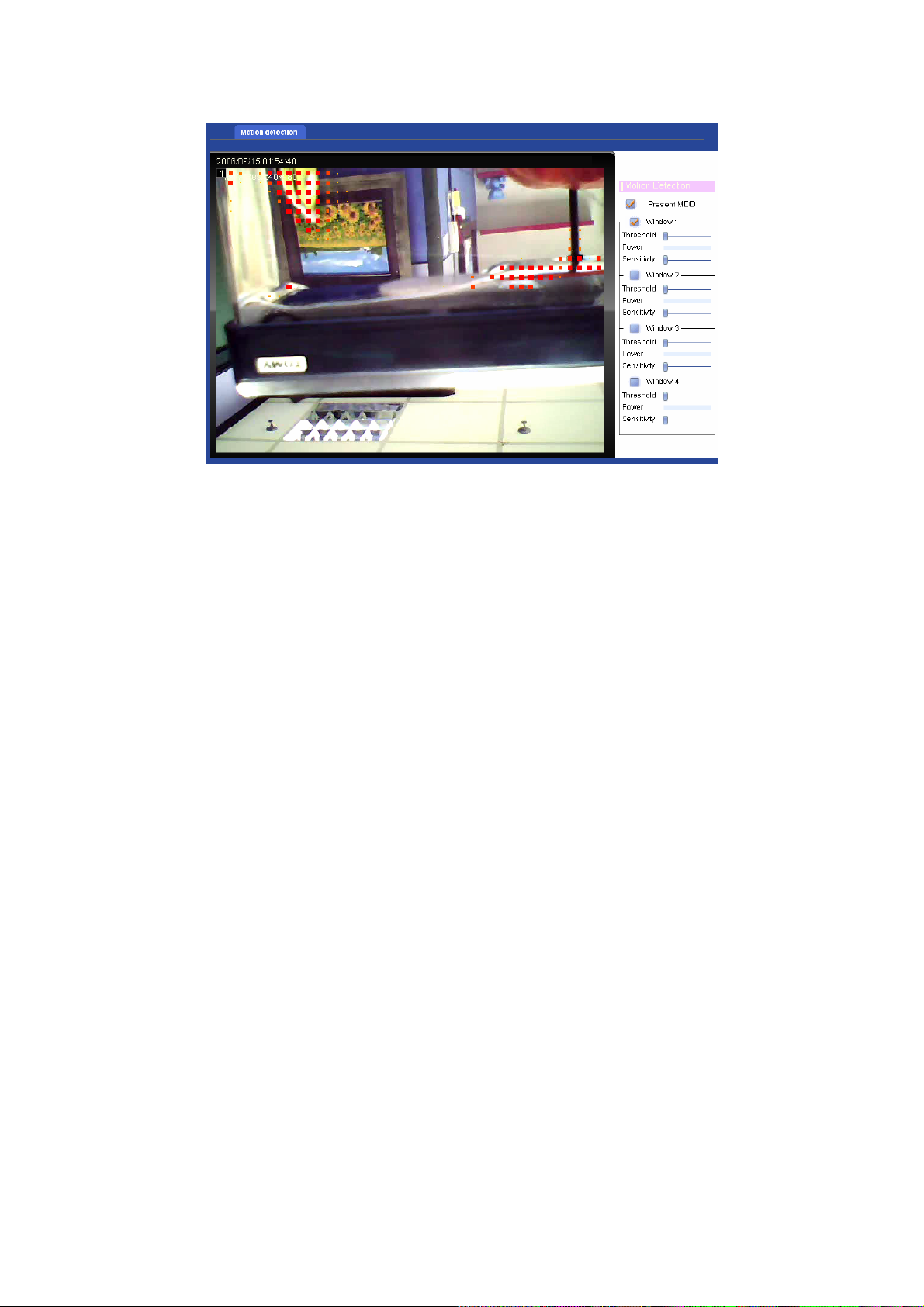
Present MDD:
To enable or disable the MDD (motion detection data) function. The motion object/area will be
marked by red block while this function is enabled.
Window 1 to 4:
User can specify up to 4 areas to monitor the image captured by this device. By dragging
mouse on the image, you can change the position and size of the window accordingly.
Threshold setting slide bar:
Define the threshold level of moving object detection that is common for all the windows. The
threshold level is used to judge whether or not there has been any motion in the window. Mov e
this bar to the right will increase the threshold. An alarm is triggered when motion that exceeds
the threshold level is detected in the window.
Move the slide bar to right will increase the threshold.
Power:
Show the detected power of the motion detection within the specified window.
Sensitivity
Define the sensitivity value of motion detection. Move this bar to the right will increase the
sensitivity.
Move the slide bar to right will increase the sensitivity.
44/57
Page 46

Appendix A: Hardware Restore
There is a button hidden under the ICA-312 housing. User must open the housing cover first
and then access this button. This button is use for hardware restore to factory default settings.
Sometimes restarting the ICA-312 will make the system back to a normal state. If the system
still got problems after reset, user can restore the factory default settings and install it again.
Restore the ICA-312:
1. Press and hold the button down continuously.
2. Wait at least 3 seconds and release the button. Then the ICA-312 has been
restored to factory default settings and reboot again.
Note: Restoring the factory default setting will lose the all previous settings included IP
address forever. User will need to run th e IPWizard program to search the device and
configure it to let the device work properly again.
45/57
Page 47
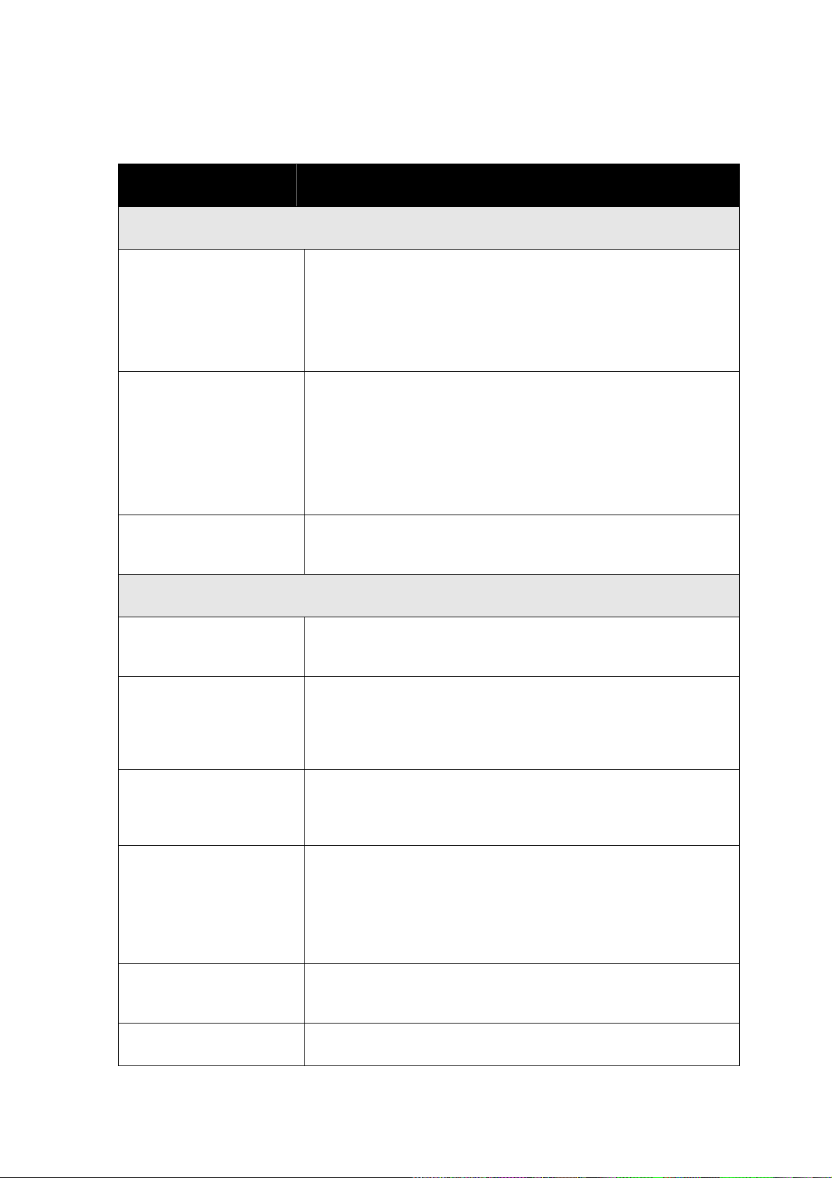
Appendix B: Troubleshooting & FAQ
Question Answer or Resolution
Features
The video and audio codec
is adopted in the ICA-312.
The maximum number of
users access ICA-312
simultaneously.
The ICA-312 can be used
outdoors or not.
The network cabling is
required for the ICA-312.
The ICA-312 utilizes MPEG-4 and M-JPEG dual compression to
providing high quality images. Where MPEG-4 is a standard for
video compression and M-JPEG is a standard for image
compression.
The audio codec is selectable by either AMR or G.726 com pressio n.
The maximum number of users is 10. However, it also depends on
the total bandwidth accessed to this device from clients. The data
throughput of the device is around 20~25Mbps. Therefore, the
actual number of connected clients is varying by settings of
resolution, codec type, frame rate and bandwidth. Obviously, the
performance of the each connected client will slow down when many
users are logged on.
Yes, this ICA-312 is weatherproof. However, it might need to be
equipped with a weatherproof case for better performance.
Install ICA-312
The ICA-312 uses Category 5 UTP cable allowing 10 and/or 100
Base-T networking.
The ICA-312 will be
installed and work if a
firewall exists on the
network.
The username and
password for the first time
or after factory default reset
Forgot the username and
password
Forgot the IP address of
the ICA-312.
IPWizard program cannot • Re power the ICA-312 if cannot find the unit within 1 minutes.
46/57
If a firewall exists on the network, port 80 is open for ordinary data
communication. This HTTP port and Video/Audio streaming ports
needs to be opened on the firewall.
Username = admin and leave password blank.
Note that it’s all case sensitivity.
Follow the steps below.
1. Restore the factory default setting by press pressing and holding
down more than 3 seconds on ICA-312.
2. Reconfigure the ICA-312.
Check IP address of ICA-312 by using the IPWizard.exe program.
Page 48

find ICA-312. • Do not connect ICA-312 over a router. IPWizard program cannot
detect ICA-312 over a router.
• If IP address is not assigned to the PC which running IPWizard
program, then IPWizard program cannot find ICA-312. Make sure
that IP address is assigned to the PC properly.
• Antivirus software on the PC might interfere with the setup
program. Disable the firewall of the antivirus software during setting
up ICA-312.
• Check the firewall setting of your PC or Notebook.
Internet Explorer does not
seem to work well with the
ICA-312
IPWizard program fails to
save the network
Make sure that your Internet Explorer is version 6.0 or later. If you
are experiencing problems, try upgrading to the latest version of
Microsoft’s Internet Explorer from the Microsoft webpage.
• Network may have trouble. Confirm the parameters and
connections of the ICA-312.
parameters.
Cannot access the login
page and other web pages
of ICA-312 from Internet
Explorer
• Maybe the IP Address of the ICA-312 is already being used by
another device or computer. To confirm this possible problem,
disconnect the ICA-312 from the network first, and then run the
PING utility to check it out.
• May be due to the network cable. Try correcting your network cable
and configuration. Test the network interface by connecting a local
computer to the ICA-312 via a crossover cable.
• Make sure the Internet connection and setting is ok.
• Make sure enter the IP address of Internet Explorer is correct. If
ICA-312 has a dynamic address, it may have changed since you last
checked it.
Access ICA-312
• Network congestion may prevent the web page appearing quickly.
Wait for a while.
The IP address and Subnet Mask of the PC and ICA-312 must be in
the same class of the private IP address on the LAN.
• Make sure the http port used by the ICA-312, default=80, is
forward to the ICA-312’s private IP address.
• The port number assigned in your ICA-312 might not be available
via Internet. Check your ISP for available port.
• The proxy server may prevent you from connecting directly to
ICA-312, set up not to use the proxy server.
• Confirm that Default Gateway address is correct.
• The router needs Port Forwarding feature. Refer to your router's
manual for details.
• Packet Filtering of the router may prohibit access from an external
47/57
Page 49

network. Refer to your router's manual for details.
• Access ICA-312 from the Internet with the global IP address of the
router and port number of ICA-312.
• Some routers reject the global IP address to access ICA-312 on
the same LAN. Access with the private IP address and correct port
number of ICA-312.
• When you use DDNS, you need to set Default Gateway and DNS
server address.
• If it’s not working after above procedure, reset ICA-312 to default
setting and installed it again.
• If the problem is not solved, the ICA-312 might be faulty. Contact
your dealer for further help.
Image or video does not
appear in the main page.
• The first time the PC connects to ICA-312, a pop-up Security
Warning window will appear to download ActiveX Controls. When
using Windows 2000 or Windows XP, log on with an appropriate
account that is authorized to install applications.
• Network congestion may prevent the Image screen from appearing
quickly. You may choose lower resolution to reduce the required
bandwidth.
Internet Explorer displays
the following message:
Setup the IE security settings or configure the individual settings to
allow downloading and scripting of unsigned ActiveX controls.
“Your current security
settings prohibit
downloading ActiveX
controls”.
The ICA-312 work locally
but not externally.
• Might be caused from the firewall protection. Check the Internet
firewall with your system or network administrator. The firewall may
need to have some settings changed in order for the ICA-312 to be
accessible outside your LAN.
• Make sure that the ICA-312 isn’t conflicting with any other web
server running on your LAN.
• Check the configuration of the router settings allow the ICA-312 to
be accessed outside your local LAN.
• Check the bandwidth of Internet connection. If the Internet
bandwidth is lower than target bit rate, the video streaming will not
work correctly.
The unreadable characters
are displayed.
Use the operating system of the selected language. Set the
Encoding or the Character Set of the selected language on the
Internet Explorer.
Frame rate is slower than
the setting.
• The traffic of the network and the object of the image affect the
frame rate. The network congestion causes frame rate slower than
the setting.
48/57
Page 50
• Check the bandwidth of Internet connection. If the Internet
bandwidth is lower than target bit rate, the video streaming will not
work correctly.
• Ethernet switching hub can smooth the frame rate especially in
viewing on the Multi-Camera screen.
Image Transfer on e-mail
or FTP does not work.
Cannot play the recorded
ASF file
• Default Gateway and DNS server address should be set up
correctly.
• If FTP does not work properly, ask your ISP or network
administrator about the transferring mode of FTP server.
Miscellaneous
Have installed Microsoft®’s DirectX 9.0 or later and use the
Windows Media Player 9 or later to play the ASF filed recorded by
the Device.
49/57
Page 51
Appendix C: PING IP Address
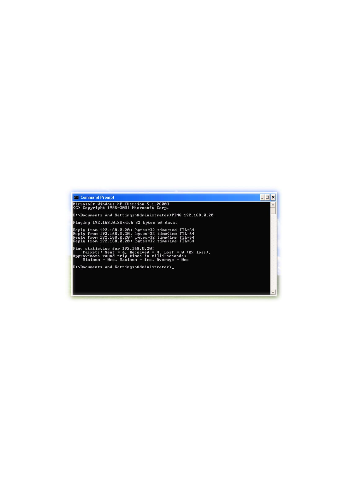
The PING (stands for Packet Internet Groper) command is used to detect whether a specific IP
address is accessible by sending a packet to the specific address and waiting for a reply. It’s
also a very useful tool to confirm ICA-312 installed or if the IP address conflicts with any other
devices over the network.
If you want to make sure the IP address of ICA-312, utilize the PING command as follows:
z Start a DOS window.
z Type ping x.x.x.x, where x.x.x.x is the IP address of the ICA-312.
The replies, as illustrated below, will provide an explanation to the problem.
If you want to detect any other devices conflicts with the IP address of ICA-312, also can utilize
the PING command but you must disconnect the ICA-312 from the network first.
50/57
Page 52
Appendix D: Bandwidth Estimation
The frame rate of video transmitted from the ICA-312 depends on connection bandwidth
between client and server, video resolution, codec type, and quality setting of server. Here is a
guideline to help you roughly estimate the bandwidth requirements for your ICA-312.
The required bandwidth depends on content of video source. The slow motion video will
produce smaller bit rate generally and fast motion will produce higher bit rate vice versa.
Actual results generated by the ICA-312 may be varying.
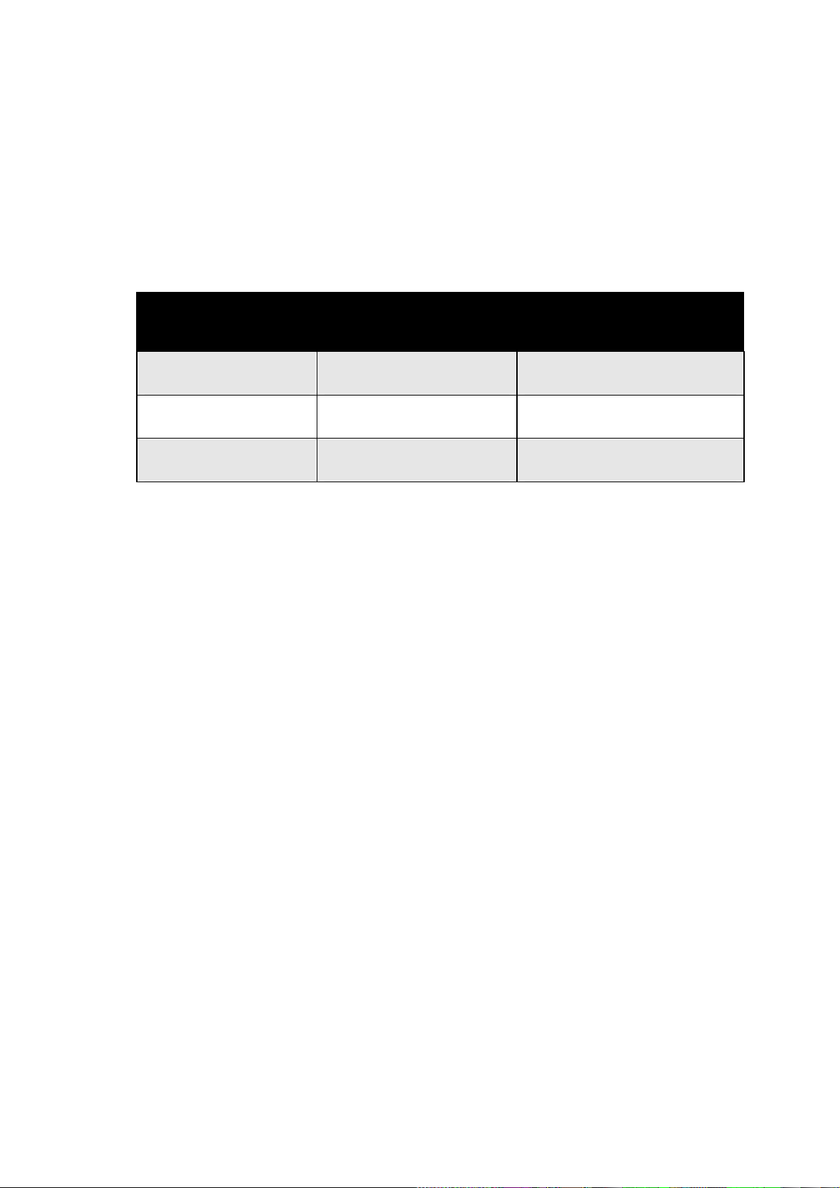
Image Resolution Average range of Data Sizes
for JPEG mode
160 x 120 (QQVGA) 3 ~ 6k byte per frame 64kbps~384kbps @ 30fps
320 x 240 (QVGA) 8 ~ 20k byte per frame 128kbps~768kbps @ 30fps
640 x 480 (VGA) 20 ~ 50K byte per frame 256kbps~4096kbps @ 30fps
Note: Audio streaming also takes bandwidth around 5 kbps to 64kbps. Most
xDSL/Cable modem upload speeds may not even reach up to 128 kbps. Thus,
you may not be able to receive any video while streaming audio on a 128 kbps or
lower connection. Even though the upload speed is more than 128kbps, for
optimal video performance, disabling audio streaming will get better video
performance.
Average bit rate for MPEG4 mode
51/57
Page 53

Appendix E: DDNS Application
1. Preface
If you have a Cable modem or xDSL, this is a great way to host your own Networked
Device or other TCP/IP Service. Get your own domain like www.yourname.com,
www.yourname.com.tw etc. (Note: This domain must be registered with Internic via
registration authorities such as Network Solutions, DirectNIC, Register.com etc). Your
domain name's dynamic IP address is automatically tracked by a DDNS server.
Host your own Networked Device and much more no matter what your computer's IP
address may be and even if you have dialup, DSL or cable modem internet connection
where your computer's IP address changes all the time!! DDNS service supports all top
level domain names including but not limited to .com, .net, .org, .to, .uk etc.
2. Ethernet Network Environment
Normally, DDNS service is only necessary for the users that could only obtain dynamic IP
addresses. As to the users that could obt ain the static valid IP address, they do not usually
have to apply the DDNS service. Before we decide if DDNS is necessary for the use rs, we
have to check what kind of Ethernet network environment we have to install our Networked
Device on.
(1) Environment of Fixed Valid IP Network
If users could obtain valid IP addresses, they could save the effort to apply DDNS service.
Because the IP address in this environment is fixed, users could input the IP address or
domain name of demo site directly in the IE browser.
(2) Environment of Dynamic IP Net work
If users is under an environment of dynamic IP network (Dial-up xDSL), they have to apply
a domain name in advance. Then apply DDNS service. Finally setup the necessary
information of DDNS and PPPoE of the Networked Device in order to let the outside
administrator be able to access through internet.
3. Application Steps – DDNS & Domain Name
(1). Visit the following web site: http://www.dyndns.org/
(2). Click “Account”
52/57
Page 54
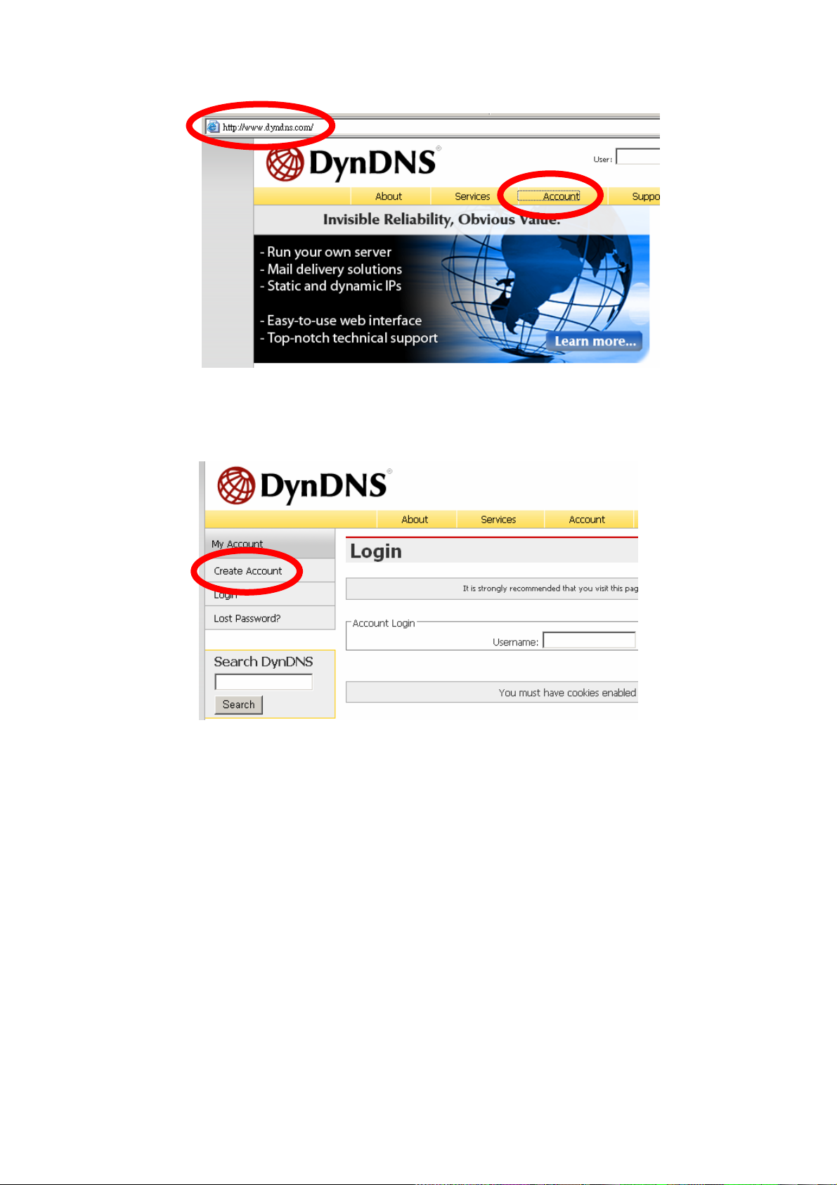
(3). After the columns show up at the left side, click “Create Account”.
(4). Fill the application agreement and necessary information.
a. Username
b. E-mail address and confirmation
c. Password and confirmation
d. Submit all the input information and finish creating an account
53/57
Page 55
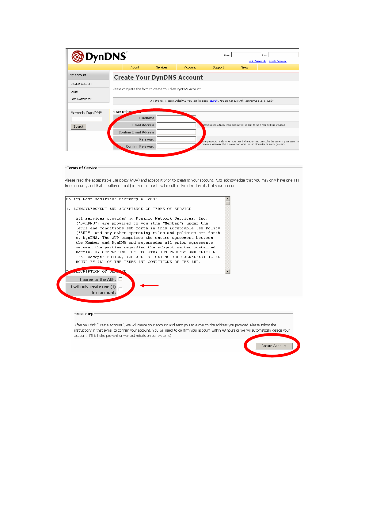
Click these two options
(5). Check your e-mail mailbox. There will be an e-mail with a title “Your DynDNS Account
Information“. Click the hyperlink address to confirm the DDNS service that you just
applied. Then DDNS you applied activated.
54/57
Page 56
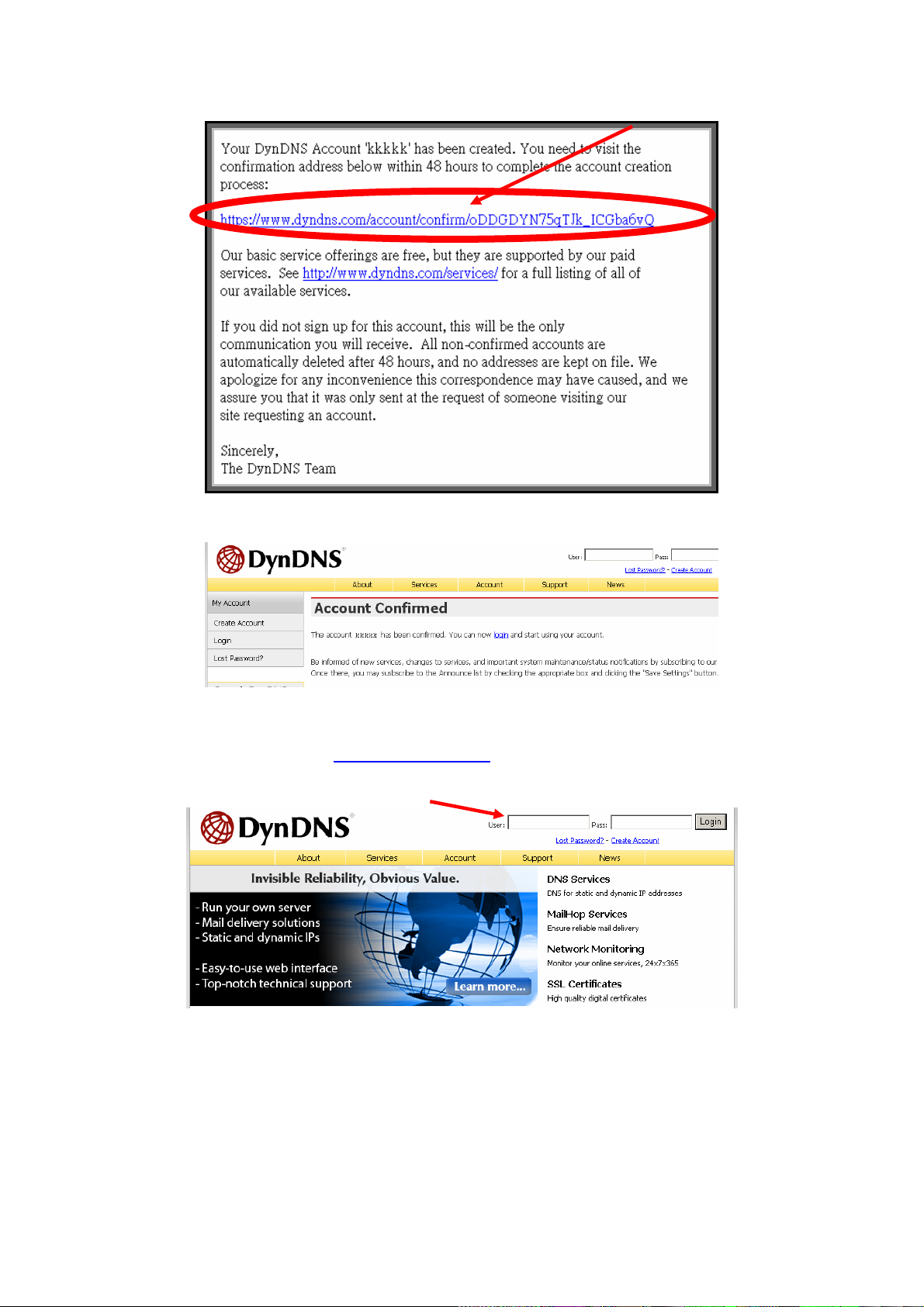
Click to confirm
(6). Enter the web page http://www .dyndns.org/
that you just applied to login administration interface of DDNS server.
again. Input your username and password
Input your account
(7). If the correct username and password are input, you can see the following picture at
the top-right of the login page.
(8). Click the “Services”.
55/57
Page 57
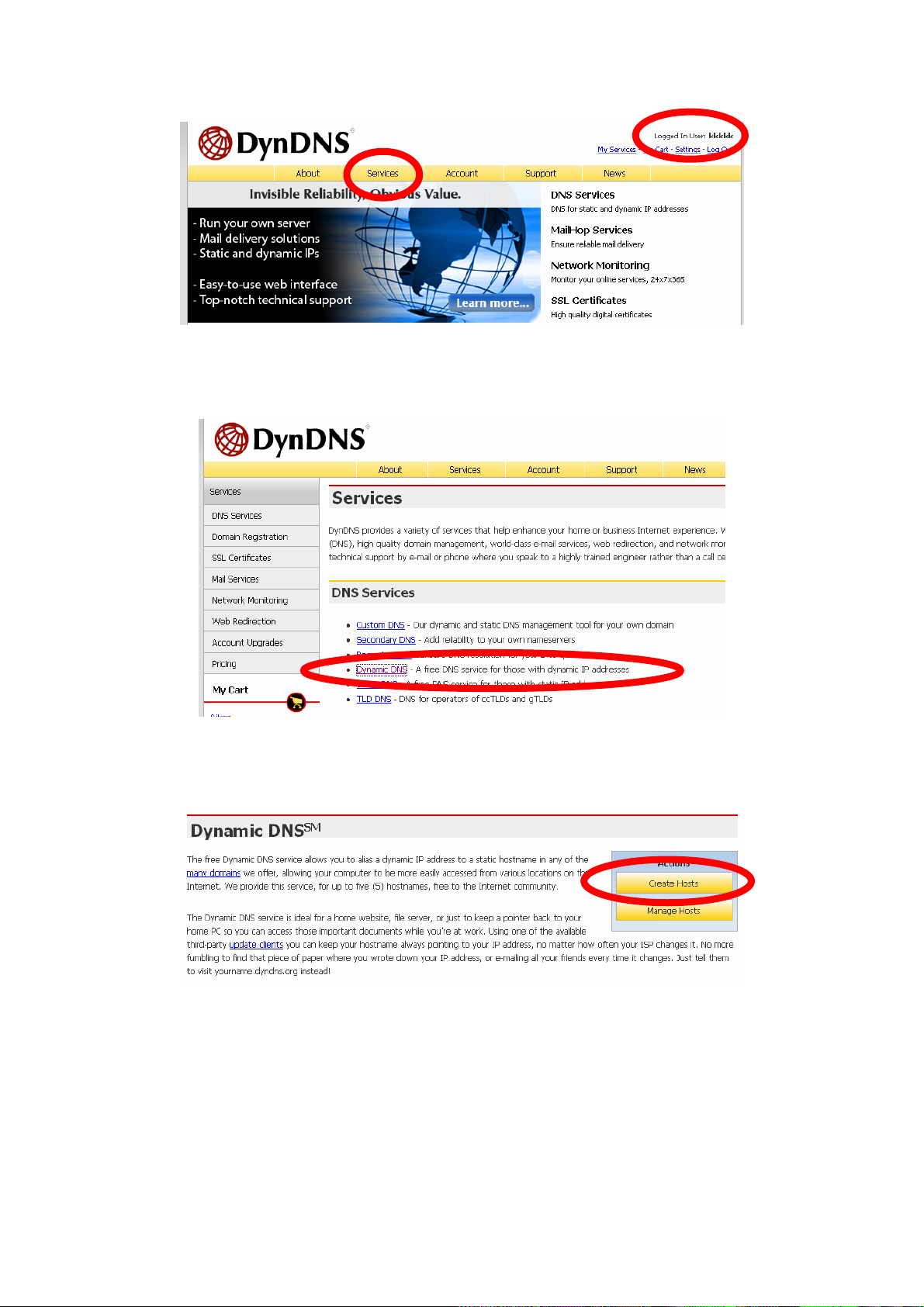
(9). Click the “ Dynamic DNS ”.
(10). Click the “Create Hosts”.
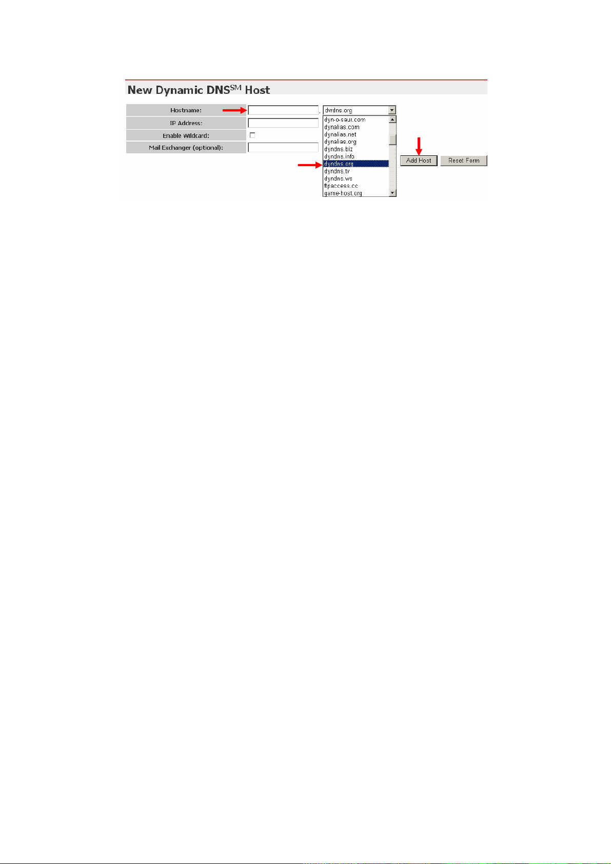
(11). We could create a domain name without any charge at this step. First, we input the
host name. (No.1) Then we pick a domain that is easy to remember. Finally (No.2), click
the “Add Host” to submit the domain name information. (No.3)
56/57
Page 58
1
3
2
4. Setup the DDNS and PPPoE of Network Device
At last, users have to enter the web page of Networked Device and setup the necessary
information of DDNS and PPPoE after the application of DDNS service. Please check the
user manual to access the DDNS and PPPoE pages. After saving the modification, restart
the device. The external users could browse the Networked Device by the input of their
domain name.
57/57
 Loading...