

Page 1
s
Megapixel FireWire Camera Megapixel FireWire Camera
System Guide System Guide
PL-A630 to PL-A660 Series Cameras PL-A630 to PL-A660 Series Cameras
Imaging Modules
3030 Conroy Road • Ottawa, Ontario • K1G 6C2 • Canada • Tel: (613) 247-1211 • Fax: (613) 247-2001
Email:
Camera
Copyright © 2000–2004 PixeLINK. All Rights Reserved.
PixeLINK
[email protected] • Web Site: www.pixelink.com
Page 2

ii
PixeLINK™ Megapixel FireWire Camera
System Guide
Copyright Notice
PL-A630 to PL-A660 Series Cameras
Copyright © 2000–2004, PixeLINK. All rights reserved.
This document contains proprietary and confidential information of PixeLINK. The contents of this document may not be copied
nor duplicated in any form, in whole or in part, without prior written consent from PixeLINK.
By purchasing this product, the Purchaser(s) and/or any subsequent legitimate owner(s) of the product, henceforth referred to as
“the Purchaser,” agree(s) to abide by the terms of this Agreement and read and recognize the following set of definitions
appertaining to the intellectual-property items and trademark references as can be found throughout this System Guide.
PixeLINK provides the information and data included in this document for the Purchaser’s benefit, but it is not possible for PixeLINK
to entirely verify and test all of this information in all circumstances, particularly information relating to non-PixeLINK manufactured
products. PixeLINK makes no warranties or representations relating to the quality, content, or adequacy of this information. Every
effort has been made to ensure the accuracy of this Guide; however, PixeLINK assumes no responsibility for any errors or
omissions in this document. PixeLINK shall not be held liable for any errors or for incidental or consequential damages in
connection with the furnishing, performance, or use of this System Guide or the examples herein.
PixeLINK assumes no responsibility for any damage or loss resulting from the use of this System Guide, loss or claims by third
parties which may arise through the use of this product, any damage or loss caused by deletion of data as a result of malfunction
or repair, or any other damage related to the use of this product or associated documentation. The information in this document is
subject to change without notice.
Definitions of Intellectual Property and Trademark Attributions
This Section is intended to ensure proper attribution and honoring of any and all trademarks and intellectual-property items in
terms of attribution to their respective owners as mentioned in this System Guide. The reader is encouraged to consult this Section
whenever uncertainty presents itself as to the terms, their meaning within the System Guide, and the trademarks and intellectualproperty items they stand to identify, whether by themselves or in conjunction with other terms and items.
PixeLINK
is either a trademark or a registered trademark of PixeLINK in Canada and/or other countries;
trademark or service mark of the Institute of Electrical and Electronics Engineers, Incorporated in the United States and/or other
countries;
other countries;
the United States and/or other countries. All other products, brand names, company names are trademarks or registered
trademarks of their respective owners.
The above Sections set forth Terms and Conditions, compliance with which constitutes a mandatory prerequisite for owning and/or
using the product for which the Guide was created. It is the Purchaser’s responsibility to ensure that the information contained
within the Sections is maintained as a part of the System Guide at all times—should the Purchaser discover that the page(s)
containing the Sections is (are) missing, and/or was not provided with the System Guide, and/or become illegible, PixeLINK should
be contacted as soon as possible and the Sections requested. PixeLINK shall not be held liable for any and all copyright violations
that may ensue in relation to its products and/or the consequences of their intended and unintended usage.
January 2004
Part Number: 03622-04
Mac, Mac OS, Macintosh, QuickTime,
Microsoft, DirectShow,
Definition of Terms
This Section is intended to define certain terminology used in this System Guide, while ensuring proper attribution and
honoring of any and all trademarks and intellectual-property items in terms of attribution to their respective owners as
mentioned in this System Guide.
The Purchaser shall hereby recognize the following definitions set herein, as can be found throughout this System Guide:
Camera
shall henceforth refer to a PixeLINK FireWire Camera or Imaging Module;
Camera Application Programming Interface;
henceforth refer to the IEEE 1394a interface specification;
multimedia software;
QuickTime multimedia software
Mac
shall henceforth refer to the Apple Macintosh computer;
; Windows
and
FireWire
and
Windows
Kit
are trademarks of Apple Computer, Inc., registered in the U.S. and
are either trademarks or registered trademarks of Microsoft Corporation in
API
shall henceforth refer to a PixeLINK Camera Kit;
DirectShow
shall henceforth refer to the Microsoft DirectShow
shall henceforth refer to the PixeLINK
QuickTime
shall henceforth refer to a Microsoft Windows operating system.
shall henceforth refer to Apple
IEEE
FireWire
is a registered
and
1394
shall
PL-A630 to PL-A660 Series Cameras PixeLINK
Megapixel FireWire Camera
Copyright © 2000–2004 PixeLINK
All Rights Reserved
System Guide
Page 3

TABLE OF CONTENTS iii
Table of Contents
1 Introduction 1
1.1 The PixeLINK Megapixel FireWire Camera.................................................................1
1.2 Topics Covered in this Guide....................................................................................2
1.3 System Requirements..............................................................................................2
1.3.1 Windows ................................................................................................................2
1.3.2 Macintosh...............................................................................................................3
1.3.3 Laptop Computers...................................................................................................3
1.4 Camera Accessories ................................................................................................3
1.5 The PixeLINK Camera Application Programming Interface .........................................4
1.6 Compatibility with Other PixeLINK Camera Products..................................................4
1.7 Related PixeLINK Documentation .............................................................................4
2 Hardware Overview 6
2.1 PL-A6xx Camera Features........................................................................................6
2.2 PL-A640 and PL-A660 Series Camera Hardware ........................................................6
2.2.2 PL-A640 and PL-A660 Camera Dimensions ...............................................................8
2.3 PL-A630 and PL-A650 Series Imaging Module Hardware............................................9
2.3.1 Imaging Module Assembly.......................................................................................9
2.3.2 FireWire Interface Board LEDs ............................................................................... 11
2.3.3 Headers ...............................................................................................................11
2.3.4 PL-A650 Series Imaging Module Dimensions...........................................................13
2.3.5 PL-A630 Series Imaging Module Dimensions...........................................................14
2.4 FireWire Connectors and Multiple Cameras ............................................................. 15
2.5 Attaching Lenses and Tripods ................................................................................ 16
2.6 Power ..................................................................................................................16
2.7 IR Filter................................................................................................................ 16
3 Host Software Overview (Microsoft Windows) 18
3.1 Overview.............................................................................................................. 18
3.2 Software Components ........................................................................................... 19
4 Exposure Methods 21
4.1 Video Mode Exposure............................................................................................ 21
4.2 Still Mode Exposure............................................................................................... 21
4.2.1 Using PL-A650 and PL-A660 Series Cameras in Still Mode........................................22
4.2.2 Using PL-A630 and PL-A640 Series Cameras in Still Mode........................................22
4.2.3 Using External Triggering, Flash and Shutter Signals ...............................................23
Appendix A. Glossary 24
TECHNICAL SUPPORT 25
INDEX 26
PixeLINK PL-A630 to PL-A660 Series Cameras
Megapixel FireWire Camera
System Guide
Copyright © 2000–2004 PixeLINK
All Rights Reserved
Page 4

iv LIST OF FIGURES
List of Figures
Figure 2.1 PL-A6xx Cameras.................................................................................................. 6
Figure 2.2 Camera Features, Top View................................................................................... 7
Figure 2.3 Camera Features, Bottom View.............................................................................. 7
Figure 2.4 Camera, Top, Side and End Views.......................................................................... 8
Figure 2.5 Camera, Bottom View (Showing Mount Holes)......................................................... 9
Figure 2.6 PL-A650 Series Imaging Module (PL-A630 Series similar) ....................................... 10
Figure 2.7 FireWire Interface Board (product may not be exactly as shown)........................... 10
Figure 2.8 External Power Header, Oriented as in Figure 2.9.................................................. 11
Figure 2.9 Enhanced Control/External Power Headers (may not be exactly as shown) .............. 12
Figure 2.10 PL-A650 Series Imaging Module, Top View.......................................................... 13
Figure 2.11 PL-A650 Series Imaging Module, Side View and End View ................................... 14
Figure 2.12 PL-A650 Series Imaging Module, Bottom View, Showing Mount Holes .................. 14
Figure 2.13 Camera C-Mount (PL-A650 and PL-A660 Series shown)........................................ 17
Figure 2.14 Camera C-Mount, Exploded View (PL-A650 and PL-A660 Series shown)................. 17
Figure 3.1 Host Software Architecture.................................................................................. 18
List of Tables
Table 1.1 PixeLINK Megapixel FireWire Camera Models ........................................................... 1
Table 2.1 FireWire Interface Board LEDs .............................................................................. 11
Table 2.2 PL-A653/PL-A654 Pinout of the Enhanced Control Header ....................................... 12
Table 2.3 PL-A633/PL-A634 Pinout of the Enhanced Control Header ....................................... 13
Table 2.4 Packet Sizes ........................................................................................................ 15
Table 2.5 Tripod Mount Selection Table................................................................................ 16
PL-A630 to PL-A660 Series Cameras PixeLINK
Megapixel FireWire Camera
Copyright © 2000–2004 PixeLINK
All Rights Reserved
System Guide
Page 5
APPENDIX A. GLOSSARY PAGE 1
1
1
1
Introduction
1.1 The PixeLINK Megapixel FireWire Camera
PixeLINK 1.3 Megapixel FireWire (IEEE 1394) Cameras offer a fast and affordable
means of viewing and capturing high quality color images on a desktop or laptop
computer. The cameras are connected to a host computer by a single FireWire interface
and all camera functions are controlled by the computer. PixeLINK supplies host
software consisting of drivers and application software called
Applications Programming Interface (API) compatible with C/C++ and Visual Basic along
with LabVIEW API function wrappers is also available. The driver supports Direct Show
and
PixeLINK Capture
provides a TWAIN interface for use with third party applications.
PixeLINK Capture
. An
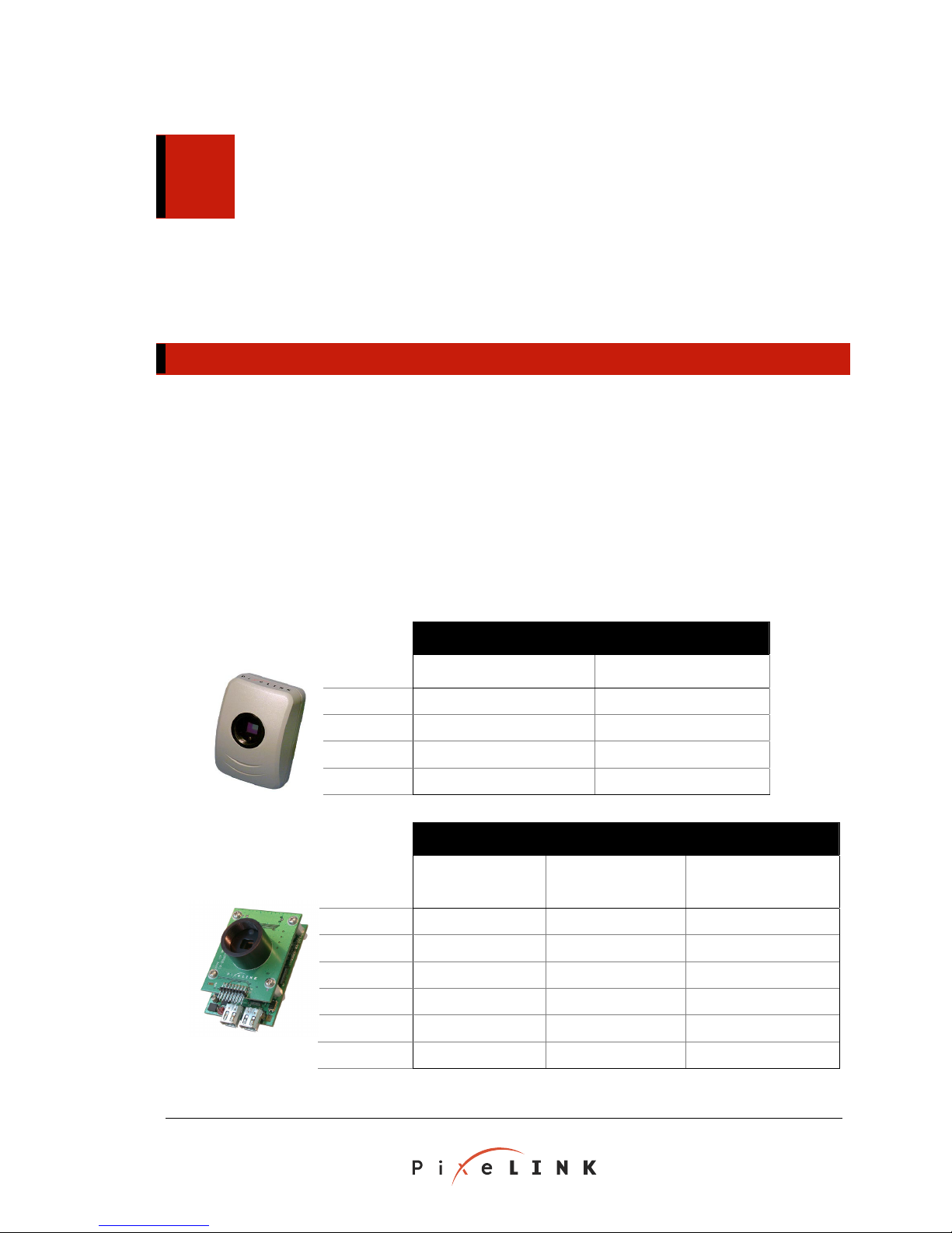
Table 1.1 PixeLINK Megapixel FireWire Camera Models
Cameras
PL-A661
PL-A662
PL-A641
PL-A642
Imaging
Modules
PL-A653
PL-A654
PL-A631
PL-A632
PL-A633
PL-A634
Color Monochrome
Color Monochrome
Camera Type
Camera Type
Enhanced
Control
PixeLINK PL-A630 to PL-A660 Series Cameras
Megapixel FireWire Camera
System Guide
Copyright © 2000–2004 PixeLINK
All Rights Reserved
Page 6

PAGE 2 APPENDIX A. GLOSSARY
1.2 Topics Covered in this Guide
This Guide provides a reference for the PixeLINK camera hardware, firmware and system
software for the camera models listed in Table 1.1 above.
Users should consult this Guide …
… before using the Enhanced Control header on a PixeLINK Imaging Module
… as a guide for mounting a camera within a system or enclosure
… to gain a basic understanding of the relationship between the camera and the
operating system
Sections include:
A description of the camera hardware—
An overview of selected host software and architecture (Microsoft Windows)—
Section 3
Notes about exposure methods—
References in the PDF version of this Guide are hyperlinked for easy navigation and
access.
Section 2
Section 4
Refer to your PixeLINK Camera User's Manual for information on
Camera software installation
PixeLINK Capture
TWAIN (Microsoft Windows) or QuickTime (Mac OS X)
1.3 System Requirements
1.3.1 Windows
One of the following Microsoft Windows operating systems must be installed:
Windows 98 Second Edition (SE)
Windows 2000, with Service Pack 1 (SP1) installed
Windows XP, with Service Pack 1 (SP1) installed
Service Packs are available for download from the Microsoft Web Site,
http://www.microsoft.com/
Hardware requirements:
Microprocessor:
Recommended—Pentium
Minimum—Pentium® III or equivalent, 450 MHz
Memory:
Recommended—128 MB RAM
Minimum—64 MB RAM
®
4 or equivalent, 1.5 GHz
PL-A630 to PL-A660 Series Cameras PixeLINK
Megapixel FireWire Camera
Copyright © 2000–2004 PixeLINK
All Rights Reserved
System Guide
Page 7

APPENDIX A. GLOSSARY PAGE 3
Desktop resolution:
Recommended—1280 × 1024
Minimum—VGA (640 × 480)
30 MB of hard drive space
A video card with 24-bit or 32-bit True Color graphics capability, at least 8 MB of
video memory and the latest vendor driver installed
Desktops: A preinstalled FireWire PCI card or a built-in FireWire port. PixeLINK
supplies a compatible PCI FireWire card with it’s camera and developer kits.
Laptops: A preinstalled FireWire Cardbus card or a built-in FireWire port
1.3.2 Macintosh
The PixeLINK Camera software is designed to work on a Macintosh platform running Mac
OS X.
Additional Software
The most recent versions of FireWire and QuickTime are available for download on
the Apple Web site (
http://developer.apple.com/quicktime/).
Additional Hardware
A FireWire (IEEE 1394) port (standard on most Mac platforms):
Built-in—B&W G3, Power Books, G4 Power Macs, iMacs, iBooks
CardBus FireWire Card (laptop computers)
Third Party OHCI or LYNX PCI FireWire Card
1.3.3 Laptop Computers
Because of the specialized hardware configurations of laptop computers, they require
additional installation considerations:
An external 12 V DC power supply—Check the connectors on the FireWire
Cardbus card or built-in FireWire port. If the connectors have six pins, the FireWire
cable may be able to supply the necessary power to the camera (refer to the
computer’s documentation for confirmation). If the connectors have four pins, the
Camera will need an external power supply.
PixeLINK provides accessory kits for both FireWire enabled laptops (product number PL1394-LAPTOP-ACC) and laptops without FireWire ports (product number PL-LAPTOPACC). Please contact your local PixeLINK dealer for more information.
1.4 Camera Accessories
Accessories such as tripod mounts, lenses, laptop accessory kits and hands-free switches
are available from PixeLINK. For a current list of accessories, visit the PixeLINK Web site
http://www.pixelink.com/ or contact your PixeLINK vendor.
at
PixeLINK PL-A630 to PL-A660 Series Cameras
Megapixel FireWire Camera
System Guide
Copyright © 2000–2004 PixeLINK
All Rights Reserved
Page 8

PAGE 4 APPENDIX A. GLOSSARY
1.5 The PixeLINK Camera Application Programming Interface
The PixeLINK Camera Application Programming Interface (API) offers application
software developers a means to adapt existing programs or develop new imaging
applications for PixeLINK cameras. The API is designed to simplify the most common
tasks associated with configuring and controlling the cameras. Applications can also
leverage the advanced command and control capabilities to enable enhanced functions
via available I²C or general purpose I/O connectors.
The PixeLINK Camera API software and reference documentation are available as
Software Developer’s Kits (SDK) and are included in PixeLINK Camera Developer's Kits.
1.6 Compatibility with Other PixeLINK Camera Products
PL-A630 to PL-A660 Series cameras are compatible with PixeLINK software from Release
3.2 and earlier. Cameras with version numbers less than 3.0 will not function with
Release 3.2 software on a Mac OS X operating system.
1.7 Related PixeLINK Documentation
• PixeLINK Megapixel FireWire Camera User’s Manual, Release 3.2
This manual describes the functionality of the PixeLINK Megapixel FireWire
camera hardware and software, including
Users should consult the User’s Manual
… before installing the camera hardware or software
… as a guide when using
PixeLINK Capture
… for tips on using the camera with TWAIN-enabled (Windows)
Sections include:
Installation of the camera hardware and software
Basic features of the camera hardware
Features and operation of
PixeLINK Capture
An overview of TWAIN (Windows)
• PixeLINK Megapixel FireWire Camera User’s Manual – Mac OS X,
Release 3.2
This manual describes the functionality of the Mac OS X version of
Capture.
PixeLINK Capture.
PixeLINK
Users should consult the User’s Manual
… before installing the camera hardware or software
… as a guide when using the Mac OS X version of
… as a guide when using QuickTime-enabled third-party software.
PL-A630 to PL-A660 Series Cameras PixeLINK
Megapixel FireWire Camera
Copyright © 2000–2004 PixeLINK
All Rights Reserved
System Guide
PixeLINK Capture
Page 9

APPENDIX A. GLOSSARY PAGE 5
Sections include:
Installation of the camera hardware and software
Basic features of the camera hardware
Features and operation of the Mac OS X version of
PixeLINK Capture
Using PixeLINK Cameras with QuickTime Video Panels.
• PixeLINK Megapixel FireWire Camera API Reference, Release 3.2
[Applies to Microsoft Windows only]
This manual provides a reference for the
PixeLINK Camera API and related software.
Sections include:
Basic principles of using the PixeLINK Camera API
A summary of the PixeLINK Camera API functions
Descriptions of individual API functions
PixeLINK PL-A630 to PL-A660 Series Cameras
Megapixel FireWire Camera
System Guide
Copyright © 2000–2004 PixeLINK
All Rights Reserved
Page 10
PAGE 6 APPENDIX A. GLOSSARY
2
2
2
Hardware Overview
2.1 PL-A6xx Camera Features
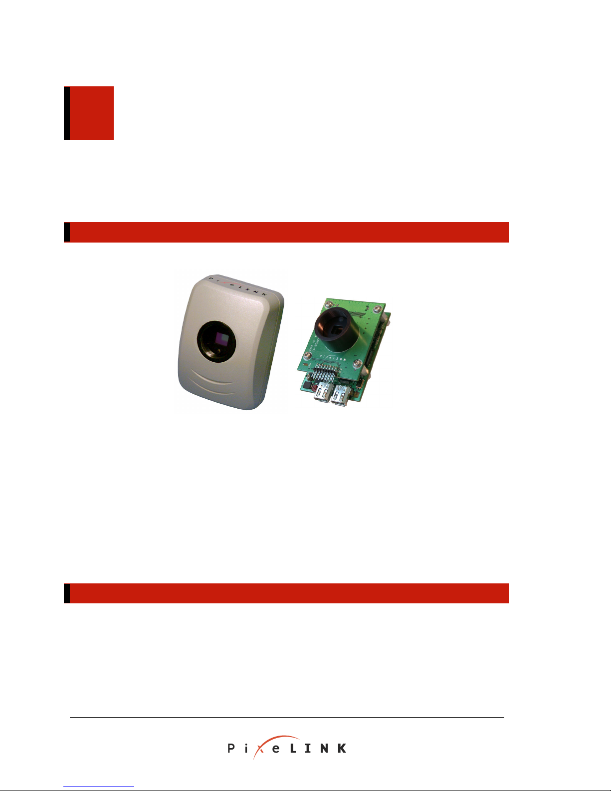
Figure 2.1 PL-A6xx Cameras
Camera Features:
1.3 Megapixel imager resolution (1280 × 1024)
8/10-bit RGB (color) or monochrome pixels
Integrated infra-red (IR) filter over the image sensor
Two FireWire connectors
Lens mount for a standard C-mount lens (1" × 32 tpi)
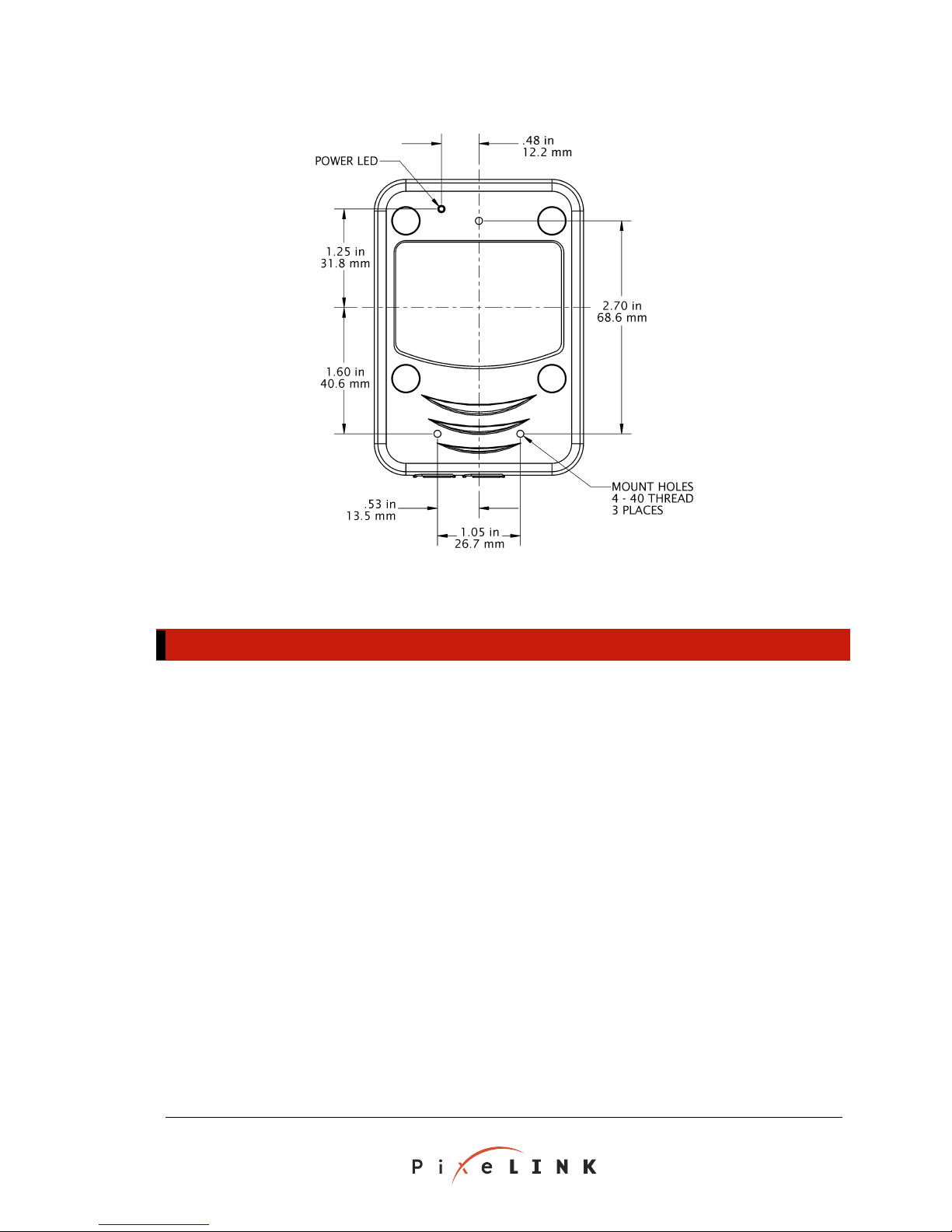
Mounting holes for a tripod or other mounting fixture (4–40 screws)
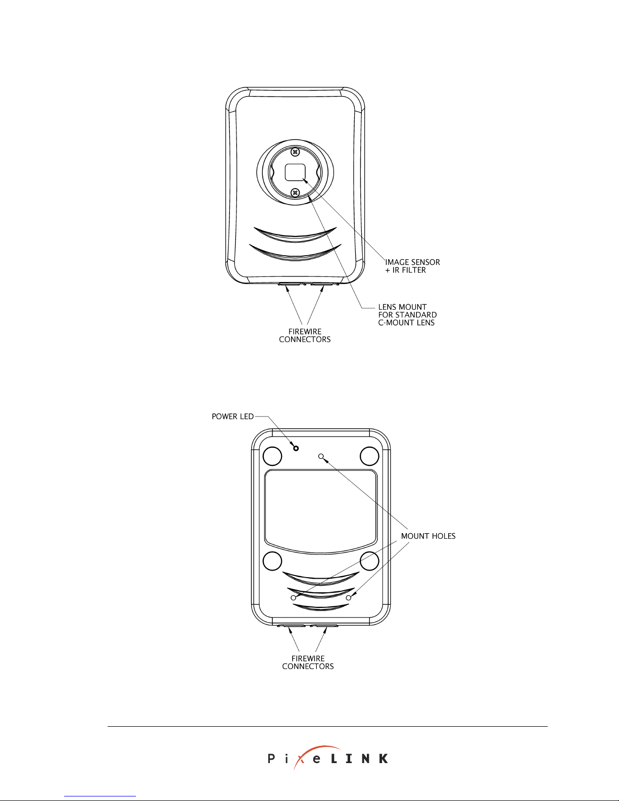
2.2 PL-A640 and PL-A660 Series Camera Hardware
The PL-A640 and PL-A660 cameras are enclosed in an aluminum housing. The cameras
have two FireWire ports, both identical, and a C-mount lens adapter with a removeable
infra-red (IR) filter. Three mounting holes are provided in the rear of the unit for
mounting to a fixture or the compatible PixeLINK 1/4-20 mount accessory. See Figure
2.2 and Figure 2.3 (on page 7) for locations of hardware features.
PL-A630 to PL-A660 Series Cameras PixeLINK
Megapixel FireWire Camera
Copyright © 2000–2004 PixeLINK
All Rights Reserved
System Guide
Page 11
APPENDIX A. GLOSSARY PAGE 7
Figure 2.2 Camera Features, Top View
PixeLINK PL-A630 to PL-A660 Series Cameras
Megapixel FireWire Camera
System Guide
Figure 2.3 Camera Features, Bottom View
Copyright © 2000–2004 PixeLINK
All Rights Reserved
Page 12
PAGE 8 APPENDIX A. GLOSSARY
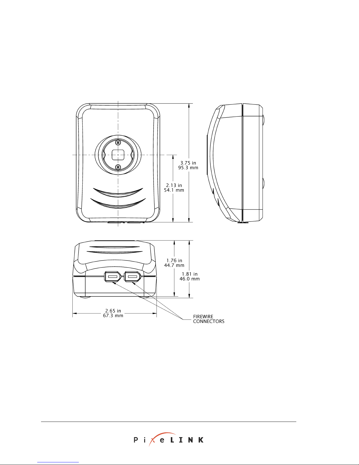
2.2.2 PL-A640 and PL-A660 Camera Dimensions
Note that outlines of the PL-A661 and PL-A662 cameras are shown in these figures; PLA641 and PL-A642 cameras differ only in the configuration of the C-mount and infra-red
(IR) filter. All measurements are ± 0.01 inches (0.3 mm).
Figure 2.4 Camera, Top, Side and End Views
PL-A630 to PL-A660 Series Cameras PixeLINK
Megapixel FireWire Camera
Copyright © 2000–2004 PixeLINK
All Rights Reserved
System Guide
Page 13
APPENDIX A. GLOSSARY PAGE 9
APPENDIX A. GLOSSARY PAGE 9
Figure 2.5 Camera, Bottom View (Showing Mount Holes)
2.3 PL-A630 and PL-A650 Series Imaging Module Hardware
2.3.1 Imaging Module Assembly
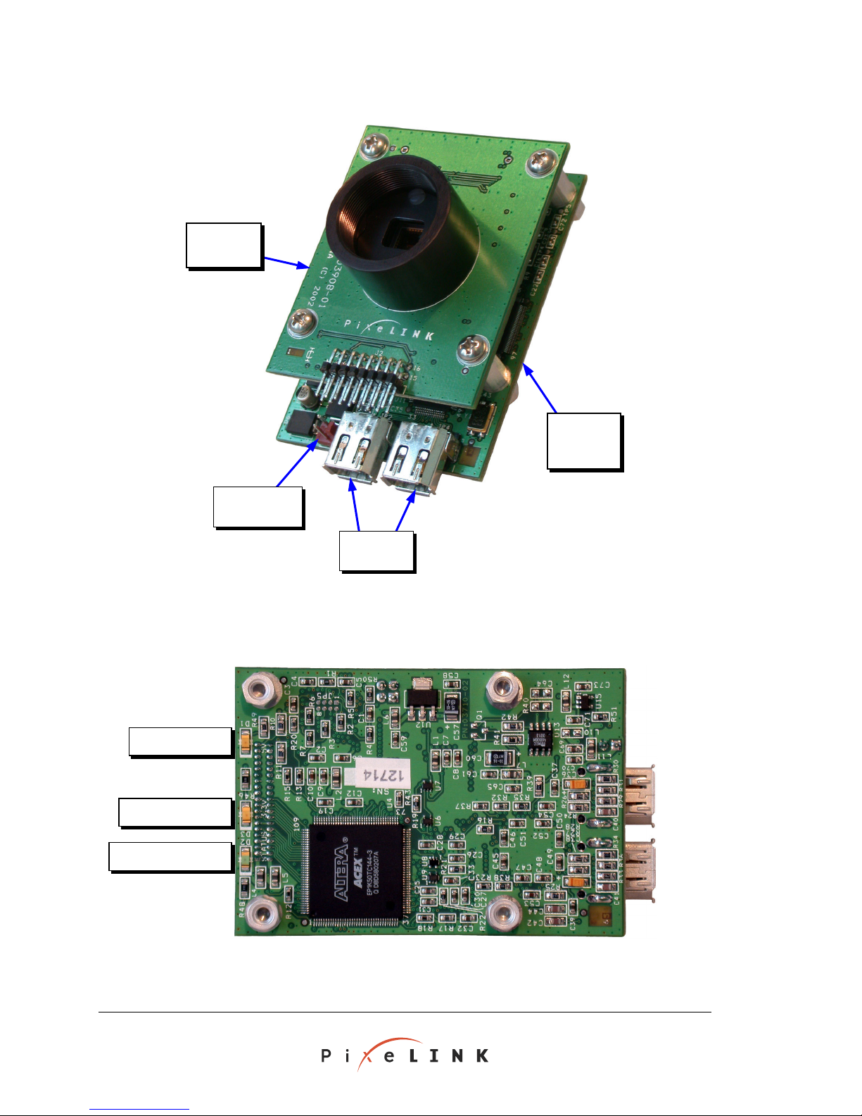
As shown in Figure 2.6 (on page 10), each PixeLINK imaging module consists of two
boards: an Imaging Assembly (the top board) and a FireWire Interface Board (the
bottom board, also shown in Figure 2.7 (on page 10). Note that an imaging module
might not be exactly as shown, depending on the model.
The camera is fitted with a 1" × 32 tpi standard C-mount lens adapter and equipped with
an Enhanced Control header (shown in Figure 2.9, on page 12). Mounting hardware may
be attached to the FireWire Interface Board at bottoms of the four spacing posts. A
mount suitable for attachment to a tripod is included in each PixeLINK Developer's Kit.
PixeLINK PL-A630 to PL-A660 Series Cameras
PixeLINK PL-A630 to PL-A660 Series Cameras
Megapixel FireWire Camera
Megapixel FireWire Camera
System Guide
System Guide
Copyright © 2000–2004 PixeLINK
Copyright © 2000–2004 PixeLINK
All Rights Reserved
All Rights Reserved
Page 14
PAGE 10 APPENDIX A. GLOSSARY
r
s
Imaging
Assembly
FireWire
Interface
Board
F
igure 2.6 PL-A650 Series Imaging Module (PL-A630 Series similar)
5 Volt Power LED
3.3 Volt Power LED
Firmware Status LED
External Power
Heade
FireWire
Connector
Figure 2.7 FireWire Interface Board (product may not be exactly as shown)
PL-A630 to PL-A660 Series Cameras PixeLINK
Megapixel FireWire Camera
Copyright © 2000–2004 PixeLINK
All Rights Reserved
System Guide
Page 15
APPENDIX A. GLOSSARY PAGE 11
2.3.2 FireWire Interface Board LEDs
The FireWire Interface Board has three LEDs, described in Table 2.1 (below).
Table 2.1 FireWire Interface Board LEDs
Function Color Location
in Figure 2.7
(page 10)
Firmware status indicator Green Left, bottom Double pulse—Firmware is running properly
3.3 V Power indicator Yellow Left, center Solid—3.3 V power present
5 V Power indicator Yellow Left, top Solid—5 V power present
Signal Type and Status
2.3.3 Headers
2.3.3.1 External Power Header
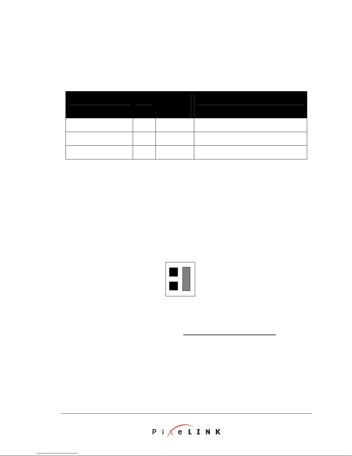
As shown in Figure 2.9 (on page 12), an external supply can be attached to the two-pin
friction lock external power header. The pinout is shown in Figure 2.8 (below).
The external power source must a power of at least 3.0 W for the Imaging
Module to operate correctly. Tw (12 V) operation is recommended, but the
voltage
may be 8 V to 30 V.
provide
elve-volt
Power
Connector
GND
8 - 30 V
Figure 2.8 wer Header, Oriented as in Figure 2.9
External Po
2.3.3.2 Enhanced Control Header [For use with Microsoft Windows only
Latch
]
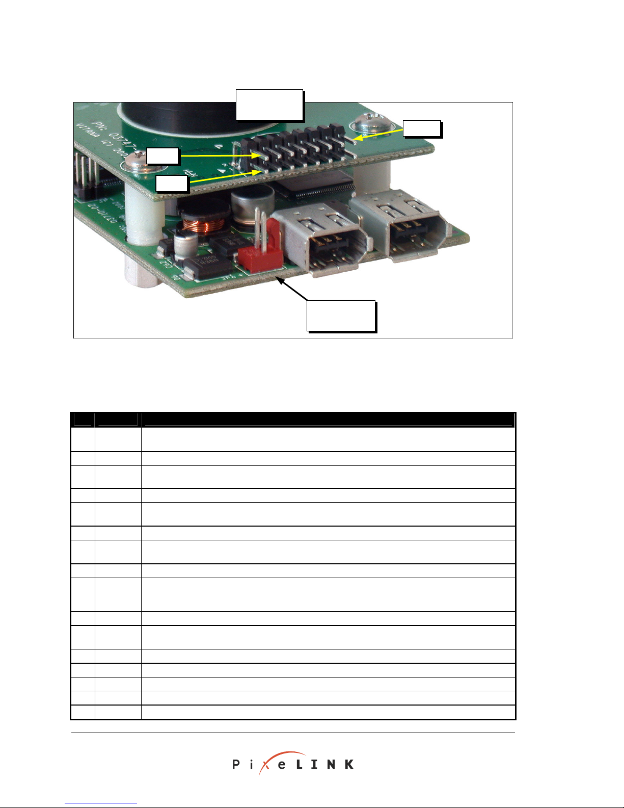
PL-A633, PL-A634, PL-A653 and PL-A654 imaging modules are each equipped with a
16-pin Enhanced Control header. This header—shown in Figure 2.9 (on page 12)—can
be connected to external devices such as a flash, trigger or I²C devices. The header
pinouts are listed in Table 2.2 (on page 12) for PL-A653 and PL-A654 imaging modules,
and in Table 2.3 (on page 13) for PL-A633 and PL-A634 imaging modules.
PixeLINK PL-A630 to PL-A660 Series Cameras
Megapixel FireWire Camera
System Guide
Copyright © 2000–2004 PixeLINK
All Rights Reserved
Page 16
PAGE 12 APPENDIX A. GLOSSARY
Enhanced
Control Header
Pin 16
Pin 2
Pin 1
External Power
Header
Fi s shown)
gure 2.9 Enhanced Control/External Power Headers (may not be exactly a
Table 2.2 ontrol Header
Pin Pin Name Function
1
TRIGGER
2
GND Ground
3
4
GND Ground
5
GP1 General p output— V HCMOS
6
GND Ground
7
FLASH External flash—5 VHCMOS
8
GND Ground
9
SH control device—5 V HCMOS outpUTTER Shutter ut; active high pulse.
10
GND Ground
11
GP2 General purpose output—5 V HCMOS output.
12
GND Ground
13
VSYNC Vertical synchronization—5 V HCMOS output; active high.
14
GND Ground
15
SCL I²C interface clock —5 V HCMOS buffered output.
16
SDA I²C interface data—3.3 V HCMOS level unbuffered bi-directional signal.
Trigger—3.3 V or 5 V TTL or high-to-low transition triggers image capture.
Refer to PixeLINK API function PimMegaReturnFrameAfterTrigger.
module.
Refer to PixeLINK API functions PimMegaGetGpo and PimMegaSetGpo.
Refer to PixeLINK API funct
Refer to the PixeLINK API functions PimMegaCaptureFrameToBitmap and
PimMegaReturnStillFrame.
Refer to the PixeLINK API functions PimMegaGetGpo and PimMegaSetGpo.
PL-A653/PL-A654 Pinout of the Enhanced C
CMOS input;
HC a bo eset the imaging /RESET Reset—5 V
MOS sign l output low for a ut 200 milliseconds at power-up to r
urpose 5 output.
output; active high pulse.
ions PimMegaCaptureFrameToBitmap and PimMegaReturnStillFrame.
PL-A630 to PL-A660 Series Cameras PixeLINK
Megapixel FireWire Camera
Copyright © 2000–2004 PixeLINK
All Rights Reserved
System Guide
Page 17
APPENDIX A. GLOSSARY PAGE 13
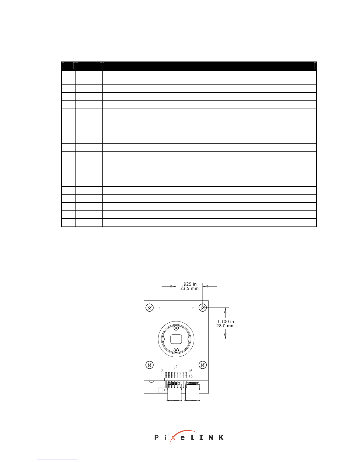
Table 2.3 PL-A633/PL-A634 Pinout of the Enhanced Control Header
Pin Pin Name Function
1
2
3
4
5
6
7
8
9
10
11
12
13
14
15
16
Trigger
GND
Reset/
GND
GP1
GND
Fla
sh
GND
SHUTTER
GND
GP2
GND
Vsynch/
GND
I2C Clock
I2C Data
Trigger—5 V (TTL) input, 10 ms pulse; active low.
Refer to PixeLINK API function PimMegaReturnFrameAfterTrigger.
Ground
Reset—TTL output; active low. Output is the Board-Level Camera reset signal to the external device.
Ground
General purpose output—TTL output.
Refer to PixeLINK API functions PimMegaGetGpo and PimMegaSetGpo.
Ground
l flash—TTL output, 10 ms pulse; active high.
Externa
r to PixeLINK API functions PimMegaCaptureFrameToBitmap and PimMegaReturn
Refe StillFrame.
Ground
Shutter control device—TTL output; active high.
Refer to PixeLINK API functions PimMegaCaptureFrameToBitmap and PimMegaReturnStillFrame.
Ground
General purpose output—TTL output.
Refer to PixeLINK API functions PimMegaGetGpo and PimMegaSetGpo.
Ground
Vertical synchronization— e vertical synchronization. TTL output. Imag
Ground
I²C interface clock —TTL output.
I²C interface data—TTL level bi-directional.
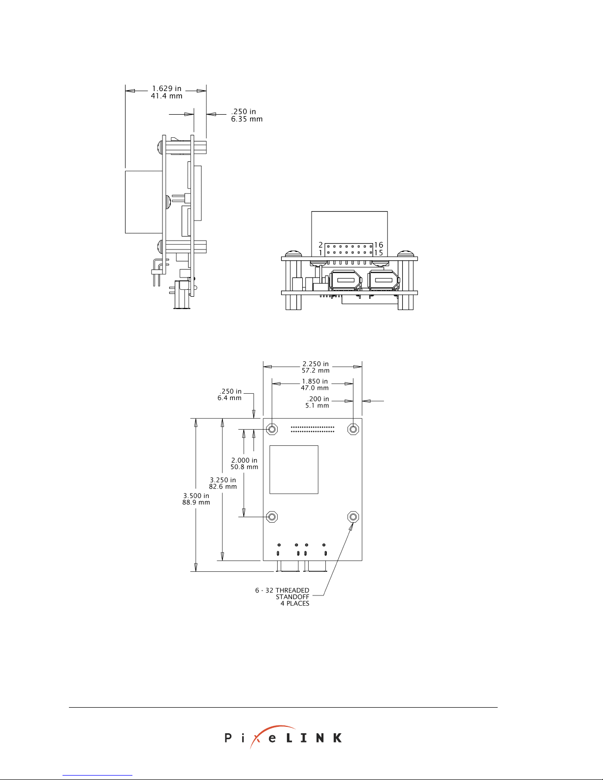
2.3.4 PL-A650 Series Imaging Module Dimensions
Dimensions of the PL-A650 Series imaging modules (PL-A653 and PL-A654) are shown in
Figures 2.10–2.12 (pages 13–14). All measurements are ± 0.005 inches (0.15 mm).
Module, Top View Figure 2.10 PL-A650 Series Imaging
PixeLINK PL-A630 to PL-A660 Series Cameras
Megapixel FireWire Camera
System Guide
Copyright © 2000–2004 PixeLINK
All Rights Reserved
Page 18
PAGE 14 APPENDIX A. GLOSSARY
Figur
e 2.11 PL-A650 Series Imaging Module, Side View and End View
Fi 2.1 odule, Bottom View, Showing Mount Holes
gure 2 PL-A650 Series Imaging M
.5
2.3 PL-A630 Series Imaging Module Dimensions
For dimensions of the PL-A630 Series Imaging Modules, please contact PixeLINK support.
(S
ee page 25 for contact information.)
PL-A630 to PL-A660 Series Cameras PixeLINK
Megapixel FireWire Camera
Copyright © 2000–2004 PixeLINK
All Rights Reserved
System Guide
Page 19
APPENDIX A. GLOSSARY PAGE 15
2.4 FireWire Connectors and Multiple Cameras
Each PixeLINK camera has two FireWire connectors (ports), allowing several devices to
be daisy-chained. The connectors are identical and either may be used to connect to the
computer. The other can be used to connect to other FireWire devices.
The number of cameras that may be managed simultaneously depends on the total
bandwidth and may be limited by power availability (see Section 2.6, below) and the
processing capabilities of the host computer.
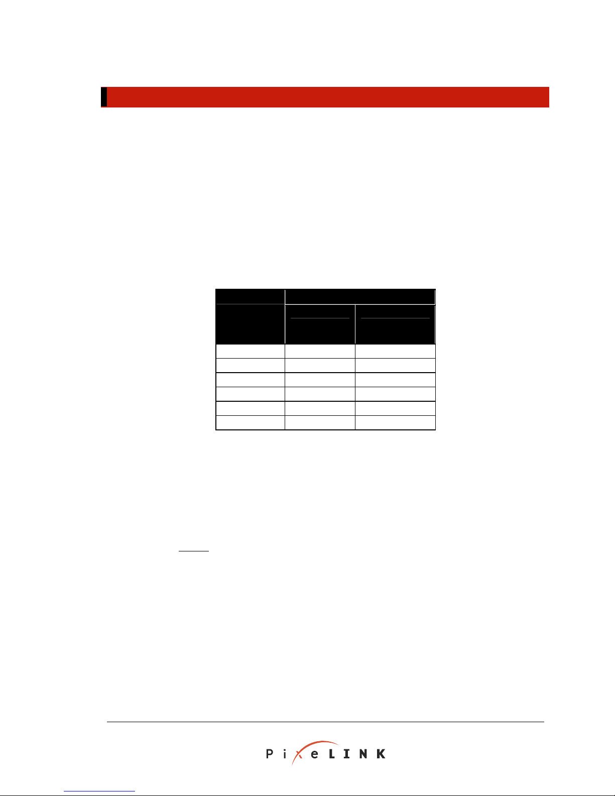
The FireWire bus requires that the sum of the packet sizes of the attached cameras be
less than 4800. Packet sizes for cameras operating with 640 × 480 and 1024 × 1280
subwindows are given in Table 2.4 (below).
Table 2.4 Packet Sizes
Clock
Frequency
(MHz)
4 640 1280
6 1280 1280
8 1280 1280
12 1920 2560
16 3200 2560
24 3840 2560
Subwindow Size
640 × 480 1024 × 1280
Example: Based on the FireWire bus only, what is the largest number of
cameras that can be managed simultaneously if each one operates
with 640 × 480 subwindow and an 8 MHz clock frequency?
Solution:
The FireWire packet limit is 4800. From Table 2.4 (above),
the packet size for a 640 × 480 subwindow at 8 MHz is 1280.
4800
753
.=
1280
To confirm:
Therefore, no more than three cameras can be
managed simultaneously at 640 × 480 and 8 MHz.
The total packet size for four cameras is 4 × 1280 = 5120, which
exceeds the FireWire packet limit. The total packet size for three
cameras is 3 × 1280 = 3840, which is less than the limit.
PixeLINK PL-A630 to PL-A660 Series Cameras
Megapixel FireWire Camera
System Guide
Copyright © 2000–2004 PixeLINK
All Rights Reserved
Page 20
PAGE 16 APPENDIX A. GLOSSARY
2.5 Attaching Lenses and Tripods
The camera can be fitted with a standard C-mount lens or attached to a microscope with
a C-mount threading. Simply attach the lens or connect to the microscope using the
threaded lens mount indicated in Figure 2.5 on page 9.
The back of the camera has three 4–40 screw holes for the attachment of a mounting
fixture such as a tripod. The imaging module can be mounting using the four standard
standoffs attached to the Interface Board.
PixeLINK offers custom mounting fixtures for attaching a tripod with a standard ¼–20
screw threading at a 90° angle to the Camera. The tripod mounts are specific to the type
of camera.
Table 2.5 Tripod Mount Selection Table.
For this camera … Use this tripod mount:
PL-A641, PL-642
PL-A661, PL-662
PL-A633, PL-634
PL-A653, PL-654
PL-640/660-CAMERA 1/4-20 MOUNT
PL-MODULE 1/4-20 MOUNT
more i PixeLINK Web site at For nformation, contact your PixeLINK vendor or visit the
http://www.pixelink.com/.
2.6 Power
The computer’s FireWire bus can supply power to the camera if the host computer has a
six-pin FireWire connector and the total power demand on the bus does not exceed the
bus capacity. Some systems—such as laptop computers or those with several FireWire
devices daisy-chained—require an external 12 V supply to power the camera.
An external power supply can be connected to the FireWire bus. Imag
ing modules are
capable of having an external power supply attached directly to a power header (see
Section 2.3.3.1, on page 11).
2.7 IR Filter
Each camera (color and monochrome) is fitted with an integrated infra-red (IR) filter over
the image sensor. This filter a ver over the image sensor. The
filter may be removed, but doing so increa
sensor. Because o the risk of dama r, only the manufacturer
should perform modifications to the camera fittings.
lso acts as a protective co
ses the likelihood of contaminating the image
ge to the sensof
The IR filter is held in place by the cam , on page 17).
PL-A630 to PL-A660 Series Cameras PixeLINK
Megapixel FireWire Camera
Copyright © 2000–2004 PixeLINK
All Rights Reserved
System Guide
era's C-mount (Figure 2.13
Page 21
APPENDIX A. GLOSSARY PAGE 17
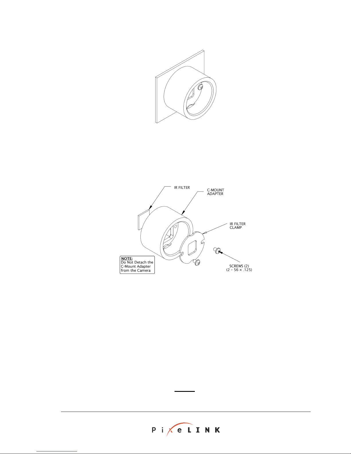
Fi
gure 2.13 Camera C-Mount (PL-A650 and PL-A660 Series shown)
To remove the IR filter:
1. Ensure that the FireWire cable is disconnected from the camer
a. Remove the lens or
other C-mount attachment.
2. Remove the screws holding the IR filter clamp in place (see Figure 2.14, below).
F
igure 2.14 Camera C-Mount, Exploded View (PL-A650 and PL-A660 Series shown)
3. Using a pair of fine-point tweezers, carefully lift out the IR Filter Clamp.
4. Place a lint-free cloth over the C-mount. Slowly tip the camera until the IR filter lands
gently in
the cloth.
5. Replace the IR filter clamp and screws.
6. Reattach the len t the FireWire cable.
Minor Clea
1. Carefull ry, compr nter of the
ning of the IR Filter
y apply puffs of d essed air to move particles off the ce
glass.
2. Remove moistened l alcohol. The swab
oils with a swab with reagent-grade isopropy
should be damp but not dripping. Do not
PixeLINK PL-A630 to PL-A660 Series Cameras
Megapixel FireWire Camera
System Guide
s or other C-mount attachment and reconnec
use acetone to clean the IR filter.
Copyright © 2000–2004 PixeLINK
All Rights Reserved
Page 22
PAGE 18 APPENDIX A. GLOSSARY
3
3
3
Host Software Overview
(Microsoft Windows)
3.1 Overview
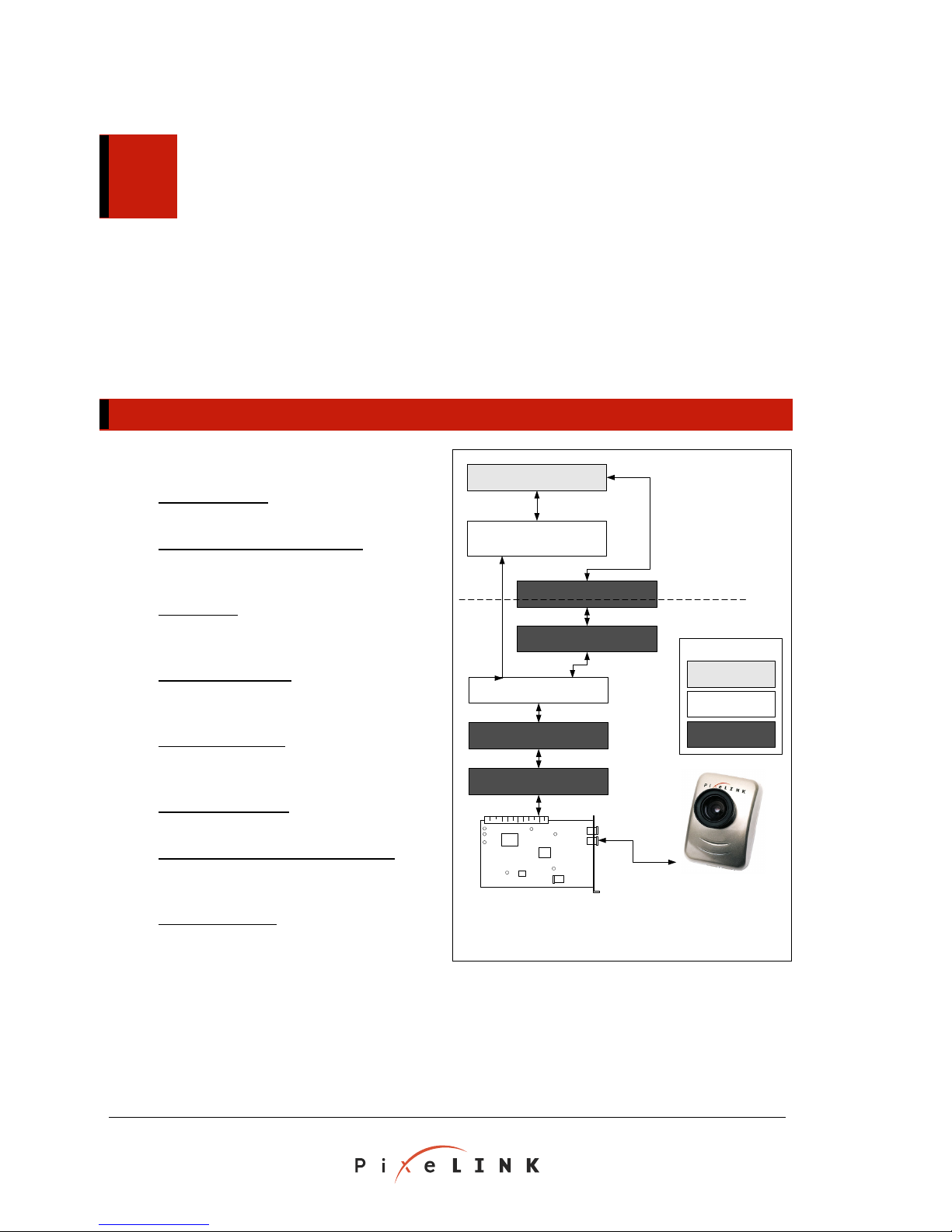
Overview of Figure 3.1
Application:User Provides a custom
control interface for the camera
PixeLINK API (PimMegaApi.dll):
software designed for the development of
custom cameras applications
DirectShow:
be used to develop custom camera
applications
Stream Class Driver:
between core PixeLINK camera software
and DirectShow
FireWire Minidriver:
software for controlling the camera and
video stream via FireWire
FireWire Bus Driver:
information sent via FireWire
OHCI FireWire Driver and Firmware:
Adapt the host interface to work with
FireWire
Pixe
LINK Camera: Receives commands
and sends video data via FireWire
Microsoft software that can
Provides a bridge
Core PixeLINK
Manages the
PixeLINK
User Application
PixeLINK API
(PimMegaApi.dll)
DirectShow
Stream Class Driver
FireWire Minidriver
FireW ire Bu s Driver
OHCI FireWire Driver
OHCI FireWire F irmw are
Figure 3.1 Host Software Architecture
User space
Kernel space
Legend
Created by the
User
Provided by
PixeLINK
Provided by
Microsoft
PixeLINK
Camera
The PixeLINK camera software consists of two types of software: the embedded
cutable software that runs exe on the camera—that is, the firmware—and the host
software that runs on the Windows system. This section focuses on the host softw
and its interaction with the embedded executable software.
PL-A630 to PL-A660 Series Cameras PixeLINK
Megapixel FireWire Camera
Copyright © 2000–2004 PixeLINK
All Rights Reserved
System Guide
are
Page 23

APPENDIX A. GLOSSARY PAGE 19
An application such as
PixeLINK Capture
(described in the PixeLINK Camera User's Manual)
can control the camera through a stack of software modules, drivers and libraries. Some of
this software is accessible to the user; the rest is in the kernel. The relationship between
user space and kernel space is illustrated in Figure 3.1 (on page 18).
3.2 Software Components
The function of each software component shown in Figure 3.1 (on page 18) is listed below.
User Application: A custom application, based on the PixeLINK API or DirectShow
(both described below), controls the camera, retrieves data from it, and displays or
stores the data. This application can be written by the user, provided by PixeLINK o
incorporated into third-party software (in cooperation with PixeLINK).
PixeLINK API (PimMegaApi.dll): This standard library provides th
with functions to control the camera and the video stream. The PixeLINK API
(described in the PixeLINK Camera API Reference) is used to create custom
applications to acce
imaging data can be formatted for sc
ss imaging data directly from the FireWire Minidriver. The
reen display or for further processing or
analysis.
a software implements a specific
DirectShow: Microsoft DirectShow multimedi
hardware and software sta
ndard for image streaming and is part of the DirectX suite
of multimedia APIs provided my Microsoft. DirectShow software can be used, as an
alternat
ive to the PixeLINK API, to integrate control of the camera with that of other
multimedia hardware and software, enhancing the functionality of the camera.
e application
r
Microsoft offers several DirectShow filters for functions such as:
• Data compression and decompression
• Data coding and decoding
• Color conversion
• Rendering (DirectDraw)
For more information about DirectShow and DirectX, visit the DirectX Web site at
http://www.microsoft.com/windows/directx/.
Stream Class Driver: This driver allows the camera to work with DirectShow by
enabling the transfer of data between DirectShow and the PixeLINK FireWire
Minidriver.
FireWire Minidriver: This PixeLINK software is the interface between the FireWire
bus and either the PixeLINK API or the Direct Show/Stream Class Driver. The
FireWire Minidriver is responsible for:
Detecting the features supported by the camera and reporting them to the
PixeLINK API or the Direct Show/Stream Class Driver;
Receiving streams of data from the FireWire Bus Driver and transmitting them
in the appropriate format to the PixeLINK API or to the Stream Class Driver;
PixeLINK PL-A630 to PL-A660 Series Cameras
Megapixel FireWire Camera
System Guide
Copyright © 2000–2004 PixeLINK
All Rights Reserved
Page 24

PAGE 20 APPENDIX A. GLOSSARY
Handling FireWire bus resets and device removal (e.g., when the cable is
unplugged from the camera)
Th
e PixeLINK FireWire mini-driver exports the following functionality to the
DirectShow:
- Exposure
- Gain
- Pan/Tilt
FireWire Bus Driver: This component perform
OHCI FireWire Firmware. That is, it manages th
s serial bus management for the
e content (video data and camera
control signals) transmitted over the FireWire cable between the camera and the host
computer. The FireWire Bus Driver can act as the cycle master, isochronous resource
man manager.
ager and bus
OHCI FireWire Driver: This component instructs the OHCI FireWire Firmware to
send and receive pack
OHCI FireWire Firmware: T
card that enables the host co
ets of information via the FireWire cable.
his generic firmware is programmed on an adapter
mputer to work with FireWire. An adapter card
designed for desktop computers is included in selected PixeLINK camera kits. If the
host desktop computer already ha
necessary. Laptop computers requir
Refer to your PixeLINK Cam
era User's Manual for more information.
PixeLINK Camera: The camera is linked to the
cable. The cable carries cont
s a FireWire port available, the card is not
e a preinstalled FireWire port or CardBus slot.
rest of the system via the FireWire
rol signals and power to the camera and the video
stream to the host computer.
PL-A630 to PL-A660 Series Cameras PixeLINK
Megapixel FireWire Camera
Copyright © 2000–2004 PixeLINK
All Rights Reserved
System Guide
Page 25

APPENDIX A. GLOSSARY PAGE 21
4
4
4
Exposure Methods
“Video Mode” and “Still Mode” refer to imager exposure methods. While all of the
PL-A630 to PL-A660 Series cameras can operate i
with Enhanced Control headers can be connected to external flash and shutter control
dev
ices (preferable for Still Mode).
PL-A Mode and Still
650 and PL-A660 Series cameras use a rolling shutter in both Video
Mode. Earlier cameras use a rolling
Still Mode.
shutter in Video Mode and simultaneous exposure in
n either mode, only cameras equipped
4.1 Video Mode Exposure
In video mode, exposure of the image sensor is controlled by a virtual window that
moves from the top to the bottom of the subwindow and then rolls up to the top of the
window for the next image frame. This virtual window is the same width as the
sub
window and has a height proportional to the exposure time. This is similar to a
sub
ling shutter in conventional photography.
rol
Row oves. The virtual
s are removed from and added to the virtual window as it m
window moves one row on its trailing
edge is a nexposed row is added to its leading
edge. e
rolls to w to start exposing rows for the next frame. Thus, at any
given ti particular row depends the amount of time since it
was
As ge frame is built from top to bottom.
Since all rows in a finished frame are exposed equally and rows are transferred
con
con o capture and interactive image control.
4.2 Still Mode Exposure
tr nsferred to the image frame and an u
Wh n the leading edge reaches the bottom of the subwindow, the virtual window
the top of the subwindo
me, the level of exposure of a
added to the virtual window.
each trailing edge row is transferred, an ima
tinually, this strategy is appropriate for still image capture in ambient lighting
ditions, vide
at a time, when the fully exposed row of pixels
Note:
External flash and shutter control devices can be connected to cameras
with Enhanced Control headers only
L-A654). P
PixeLINK PL-A630 to PL-A660 Series Cameras
Megapixel FireWire Camera
System Guide
(PL-A633, PL-A634, PL-A653,
Copyright © 2000–2004 PixeLINK
All Rights Reserved
Page 26

PAGE 22 APPENDIX A. GLOSSARY
4.2.1
Using PL-A650 and PL-A660 Series Cameras in Still Mode
PL-A650 and PL-A660 Series cameras return a still frame using the same rolling shutter
techniq
camera e capture under ambient light by providing consistent exposures
ue used for a video frame. These cameras therefore respond better than earlier
s to still imag
throughout the frame. However, if used with synchronized flash, a slightly different
approach m st be employed. An exposure time of sufficient duration to integrate all
u
rows in the active region of interest must be used, with the flash firing between the time
of all rows being simultaneously exposed and prior to the start of data read-out.
To determine the exposure and flash timing, consider the camera clock rate, size of the
reg
ion of interest (columns and rows), and decimation. The simplest way to do so is to
use
PixeLINK Capture
Wit
h the video preview playing, observe the measured frame rate. Take the inverse of
this exposure time required for a still-image capture with an
number to get the minimum
or the
PL-A6xx Application
and set the appropriate subwindow size.
external flash. Use this number as a starting point to determine the proper exposure
time camera operating at
and flash delay for your application. For example, with the
12 MHz, the full-resolution frame rate is 11.7 fps. The minimum still frame exposure is
then (1/11.7) = 85.5 ms. In our tests, we chose an exposure time of 120 ms to add a
gen
erous buffer. We chose a flash delay of 90 ms as a starting point, and, after some
exp
erimentation, we discovered that having the flash fire 110 ms after the trigger would
pro
duce good results.
4.2.2 Mode
Using PL-A630 and PL-A640 Series Cameras in Still
When in Still Mode, the entire subwindow of a PL-A630 or PL-A640 Series camera is
exposed simultaneously for a specified exposu
re time, rather than using the row-by-row
rolling shutter strategy of Video Mode. Exposure times can range from sub-milliseconds
about half a second. However, the build-up of dark current noise will be noticeable in
to
the output image for exposure times greater than 100 ms.
After the specified exposure time has elapsed, the image sensor is read out from top to
bottom at maximum speed. So, under ambient light conditions, the bottom rows of the
image sensor would continue to be exposed for the length of time required for read-out.
This results in the image being over-exposed towards the bottom of the image. Thus, it
is usually best to use Still Mode under controlled lighting conditions.
For Enhanced Control cameras (PL-A633 and PL-A634), one method to control the
lighting conditions is to use the built-in capability to synchronize a flash pulse during the
still frame capture under dark conditions. (In the PixeLINK Camera API, refer to API
functions
PimMegaReturnFrameAfterTrigger
and
PimMegaReturnStillFrame
.) Where dark
conditions are not possible and ambient light cannot be controlled, an electronically
triggered shutter can be used to cut off the ambient light at the end of the specified
exposure time. With the shutter closed, the read out from the image sensor can proceed
without any further influence from ambient light.
The PixeLINK Camera API functions also provide the ability to control a shutter,
synchronized with a still frame capture. Exposure times, flash pulse timing, and shutter
timing signals can be specified to 1/10 of a millisecond.
PL-A630 to PL-A660 Series Cameras PixeLINK
Megapixel FireWire Camera
Copyright © 2000–2004 PixeLINK
All Rights Reserved
System Guide
Page 27

APPENDIX A. GLOSSARY PAGE 23
4 Using External Triggering, Flash and Shutter Signals
.2.3
Note:
External flash and shutter control devices can be connected to cameras
with Enhanced Control headers only
PL-A654).
(PL-A633, PL-A634, PL-A653,
PixeLINK cameras with Enhanced Control headers can receive external triggering signals
and can issue flash and shutter timing controls. These signals are controlled by the
PixeLINK API functions
PimMegaReturnFrameAfterTrigger
and
PimMegaReturnStillFrame
.
•
PimMegaReturnFrameAfterTrigg
er
puts the camera into a trigger mode and begins to
capture a still image no more than 90 µs after an external trigger signal is detected.
PimMegaReturnStillFrame
•
be used
as a software trigger. However, due to operating system and interface
returns a still frame immediately after being called and can
delays, the minimal response time will be 15 ms with possible delays greater than 60
ms depending on the system configuration.
Flash and shutter timing controls pro
delay in milliseconds following the trigger signal
vided to the PixeLINK API functions represent the
. The delays are accurate to one decimal
place (0.1 ms). It is important to note that negative numbers are allowed. In the case
where a negative delay is used with an external trigger, the timing signals occur in order.
For example, with a flash delay of –15 ms and shutter delay of –5 ms, on receipt of the
trigger signal the flash signal will be fired immediately, followed 10 ms later by the
shutter signal. 5 ms after the shutter, the camer
a will start the exposure.
The shutter timing signals also include a shutter close delay to close an external shutter
following an exposure.
PixeLINK PL-A630 to PL-A660 Series Cameras
Megapixel FireWire Camera
System Guide
Copyright © 2000–2004 PixeLINK
All Rights Reserved
Page 28

PAGE 24 APPENDIX A. GLOSSARY
Appendix A.
1394 Short for the IEEE 1394 digital bus protocol (also known as
FireWire, a trademark of Apple Computer, Inc.)
API Application Programming Interface
DLL Dynamic Link Library
FireWire Apple Computer’s trademark for the IEEE 1394 digital bus protocol
fps Frames Per Second
GPO General Purpose Output
I²C Inter-IC (also known as I2C), a bus standard invented by Philips
IEEE Institute of Electrical and Electronics Engineers
MB Megabyte
MHz Megahertz
OHCI Open Host Controller Interface
PC Personal Computer
PCI Peripheral Component Interconnect
preview windowThe window used to display video images on the screen. The
size is the same number of rows and columns as in the image.
Glossary
default
QuickTime Apple Computer multimedia software
RAM Random Access Memory
ROM Read-Only Memory
sensor The Camera’s image sensing chip
subwindow The area exposed on the imager (not a window defined for viewing
the image on the screen)
TWAIN An image capture standard typically used as an interface between
image processing software and a camera or scan
ner
PL-A630 to PL-A660 Series Cameras PixeLINK
Megapixel FireWire Camera
Copyright © 2000–2004 PixeLINK
All Rights Reserved
System Guide
Page 29

APPENDIX A. GLOSSARY PAGE 25
Te t chnical Suppor
Tech Notes
Tech Notes o
http://supp
Download the Latest Software and Firmware
We recommend that you check
v
ersions of your PixeLINK software and firmware.
Technical Questions
Plea
se follow these steps before contacting our technical support team:
• Review the relevant sections of the documentation.
• Check the PixeLINK Support Site for
o new software and firmware;
o applicable Tech Notes.
• Carefully document the problem you are experiencing, noting any warning or
error messages that may appear during operation.
• Have your camera's serial number and other identifying inform
The serial number can be found on the camera, on the “About” screen in
PixeLINK
PimMegaGetHardwareVersion.
n a variety of topics are available on the PixeLINK Support Site, at
ort.pixelink.com/.
http://support.pixelink.com/ regularly for the latest
Capture,
or by using the PixeLINK Camera API function
ation at hand.
PixeLINK PL-A630 to PL-A660 Series Cameras
Megapixel FireWire Camera
System Guide
PixeLINK Customer Support
Email: [email protected]
PixeLINK Support Site: http://support.pixelink.com/
PixeLINK Main Site: http://www.pixelink.com/
Copyright © 2000–2004 PixeLINK
All Rights Reserved
Page 30

PAGE 26 APPENDIX A. GLOSSARY
Index
Acce
ssories—3
Camera dimensions—8
Camera models—1
C-mount—9, 16, 17
Dimensions—13, 14
Enhanced Contr
22, 23
Enha
nced Control header pinout—11, 12, 13
Expo
sure—20, 21, 22, 23
Expo
sure time—21, 22
FireW
ire connectors—3, 4, 6, 15
FireW
ire interface board—9, 10, 11
Flas
h—11, 12, 13, 21, 22, 23
GPO
—24
Imag
ing modules—11, 13, 14, 16
Insta
llation—4, 5
IR fil —6, 16, 17
ter
IR fil
ter, removal—17
LED
s—11
Lens
es—3, 6, 9, 16, 17
Mac OS X—2,
ol header—1, 2, 9, 11, 12, 13, 21,
3
Multiple cameras, controlling—15
PixeLINK Camera Applicatio
Interface
25
Power—3, 11, 12, 15, 16, 20
Power, external—3, 11, 12, 16
Preview window—24
QuickTime—2, 3, 24
Rolling shutter—21, 22
Serial number—25
Shutter—21, 22, 23
Still mode—2, 21, 22
Subwindow—15, 21, 22, 24
Technical Support—25
Trigger—11, 12, 13, 22, 23
Tripods—16
TWAIN—
Video compression—19
Video mode—21, 22
Windows—2,
(API)—4, 5, 12, 13, 18, 19, 22, 23, 24,
2, 4, 24
4, 5, 11, 18
n Programming
PL-A630 to PL-A660 Series Cameras PixeLINK
Megapixel FireWire Camera
Copyright © 2000–2004 PixeLINK
All Rights Reserved
System Guide
 Loading...