

Page 1
X-Series Hyperconverged Nodes
Powered by Acuity 2.3
Setup & User Guide
Document Version 1.0
January 15, 2018
Page 2

X-Series Hyperconverged Nodes Powered by Acuity
Setup & User Guide, v1.0
Purpose
This edition applies to Pivot3’s X-Series Hyperconverged Nodes powered by the Acuity software platform (Version
2.3.1 and above) and to any subsequent releases until otherwise indicated in new editions. Specific
documentation on other Pivot3 offerings are available in the Pivot3 documentation repository.
This document contains information proprietary to Pivot3, Inc. and shall not be reproduced or transferred to
other documents or used for any purpose other than that for which it was obtained without the express written
consent of Pivot3, Inc.
How to Contact Pivot3
Pivot3, Inc. General Information: [email protected]
221 West 6th St., Suite 750 Sales: [email protected]
Austin, TX 78701 Tech Support: [email protected]
Tel: +1 512-807-2666 Website: www.pivot3.com
Fax: +1 512-807-2669 Online Support: support.pivot3.com
About This Guide
This document provides procedures for:
• Connecting X-Series Hyperconverged Nodes powered by Acuity to the VMware and ESXi management
networks
• Combining nodes to create an Acuity vPG
This guide is written for Service Engineers and System Administrators configuring a Pivot3 X-Series Solution. The
Pivot3 nodes should be set up as described in the appropriate hardware setup guide, and the procedures in this
document require an understanding of the following:
• The operating systems installed on the application servers connected to the Acuity vPG
• Communication protocols installed on local application servers
• vSphere Client for access to VMware ESXi hosts or vCenter
© Copyright 2018 Pivot3, Inc.
All rights reserved. Specifications are subject to change without notice. Pivot3, Acuity, RAIGE, Pivot3 vSTAC, Pivot3 vSTAC OS, Pivot3 vSTAC Enterprise
HCI, Pivot3 vSTAC P Cubed, Pivot3 vSTAC R2S, Pivot3 vSTAC Edge, Pivot3 vSTAC Manager, Pivot3 vSTAC Watch, Pivot3 Virtual Security Server (VSS),
Pivot3 Enterprise HCI, and High-Definition Storage are trademarks or registered trademarks of Pivot3. All other brands or products are trademarks or
registered trademarks of their respective holders and should be treated as such. Pivot3 reserves the right to make changes or corrections to this
document as needed without notification.
| 2
DOC-246-GDE-Pivot3 Acuity 2.3 Setup & User Guide-v1.0.docx
Page 3

X-Series Hyperconverged Nodes Powered by Acuity
Setup & User Guide, v1.0
Table of Contents
SECTION 1 INSTALL ACUITY-BASED PIVOT3 NODES ....................................................................................................................... 7
I
NSTALL PIVOT3 NODES................................................................................................................................................................... 7
S
ECTION 2 ACUITY NODES: DISKS & NETWORK PORTS ................................................................................................................. 8
X5-6500
X5-6500
X5-6000
X5-6000
X5-2500
X5-2500
X5-2000
X5-2000
NVM
S
ECTION 3 CONFIGURE ESXI FOR VMWARE ACCESS ................................................................................................................... 13
C
ONFIGURE THE IP ADDRESSES FOR THE VMWARE MANAGEMENT NETWORK .......................................................................... 13
C
ONFIGURE SSH ........................................................................................................................................................................... 17
S
ECTION 4 INSTALL PLUGIN FOR WINDOWS ................................................................................................................................ 18
D
OWNLOAD AND OPEN PLUGIN EXECUTABLE .............................................................................................................................. 18
F
OLLOW INSTALLATION WIZARD .................................................................................................................................................. 18
(D1) FLASH ACCELERATOR NODE ................................................................................................................................... 8
(L1) FLASH ACCELERATOR NODE ................................................................................................................................... 8
(D1) FLASH STANDARD NODE ......................................................................................................................................... 9
(L1) FLASH STANDARD NODE ......................................................................................................................................... 9
(D1) HYBRID ACCELERATOR NODE .............................................................................................................................. 10
(L1) HYBRID ACCELERATOR NODE .............................................................................................................................. 10
(D1) HYBRID STANDARD NODE .................................................................................................................................... 11
(L1) HYBRID STANDARD NODE .................................................................................................................................... 11
E PCIE FLASH LED STATUS DEFINITIONS ........................................................................................................................... 12
S
ECTION 5 INSTALL PLUGIN FOR LINUX ....................................................................................................................................... 26
B
EFORE YOU START ...................................................................................................................................................................... 26
D
OWNLOAD AND OPEN PLUGIN PACKAGE ................................................................................................................................... 26
P
REPARE ENVIRONMENT ............................................................................................................................................................... 26
S
ECTION 6 NETWORK FINE TUNING ............................................................................................................................................. 32
T
IME SYNCHRONIZATION .............................................................................................................................................................. 32
S
ECTION 7 NAVIGATING THE PLUGIN ............................................................................................................................................ 38
L
OG IN TO VSPHERE WEB CLIENT ................................................................................................................................................. 38
D
ASHBOARD OVERVIEW - HOME ................................................................................................................................................... 38
D
ASHBOARD OVERVIEW – VIRTUAL PERFORMANCE GROUP ....................................................................................................... 41
P
ROVISIONING OVERVIEW: STORAGE PROVISIONING .................................................................................................................. 43
C
ONFIGURE TAB: OVERVIEW ......................................................................................................................................................... 47
3
|
DOC-246-GDE-Pivot3 Acuity 2.3 Setup & User Guide-v1.0.docx
Page 4

X-Series Hyperconverged Nodes Powered by Acuity
Setup & User Guide, v1.0
ACUITY SOFTWARE PLATFORM: NODE ICONS EXPLAINED ........................................................................................................... 49
T
OOLBOX: OVERVIEW & REPORTING ............................................................................................................................................ 50
VCENTER ALARMS & NOTIFICATIONS ........................................................................................................................................... 56
T
ASKS............................................................................................................................................................................................. 56
W
EB PLUGIN ALARMS AND LOGS .................................................................................................................................................. 57
C
HANGING VMWARE VCENTER CREDENTIALS .............................................................................................................................. 58
P
LUGIN TROUBLESHOOTING ........................................................................................................................................................ 58
S
ECTION 8 CONFIGURE NIC PORTS FOR PIVOT3 FEATURES ...................................................................................................... 60
C
ONFIGURE MANAGEMENT NIC IN PIVOT3 VCENTER PLUGIN .................................................................................................... 60
S
ECTION 9 CREATE A PIVOT3 VPG ............................................................................................................................................... 61
D
ISCOVER NODES .......................................................................................................................................................................... 61
C
REATE AN ACUITY VPG ................................................................................................................................................................ 62
A
DD AN N5 STORAGE NODE.......................................................................................................................................................... 63
A
SSIGN IP ADDRESSES FOR ISCSI CONNECTIVITY ...................................................................................................................... 64
S
ECTION 10 HOST ACCESS GROUPS .......................................................................................................................................... 66
H
OST ACCESS GROUP BASICS ...................................................................................................................................................... 66
C
REATE A HOST ACCESS GROUP .................................................................................................................................................. 67
S
ECTION 11 CREATE VOLUMES & ASSOCIATED DATASTORES .................................................................................................. 69
C
REATING AN ACUITY VOLUME ..................................................................................................................................................... 70
C
REATING A VSTAC VOLUME ........................................................................................................................................................ 71
C
REATE AN N5 STORAGE VOLUME ............................................................................................................................................... 73
P
ERFORMANCE POLICIES .............................................................................................................................................................. 75
S
ERVICE LEVELS – BEST PRACTICES & BEHAVIOR ....................................................................................................................... 76
A
CUITY ESXI HOSTS AND MAINTENANCE MODE .......................................................................................................................... 78
A
DDING ESXI HOSTS & DATASTORES .......................................................................................................................................... 78
S
ECTION 12 SNAPSHOT MANAGEMENT ...................................................................................................................................... 81
S
NAPSHOTS OVERVIEW ................................................................................................................................................................. 81
P
ROTECTED HOSTS ....................................................................................................................................................................... 82
S
CHEDULES ON A VOLUME OR AN APPLICATION GROUP ............................................................................................................. 87
P
ROTECTION POLICIES EXPLAINED .............................................................................................................................................. 88
W
ORKING WITH PROTECTION POLICIES ....................................................................................................................................... 88
R
ECOVERING A SNAPSHOT ............................................................................................................................................................ 92
| 4
DOC-246-GDE-Pivot3 Acuity 2.3 Setup & User Guide-v1.0.docx
Page 5

X-Series Hyperconverged Nodes Powered by Acuity
Setup & User Guide, v1.0
RD
3
PARTY BACKUP APPLICATIONS ............................................................................................................................................... 96
S
ECTION 13 REPLICATION .......................................................................................................................................................... 97
A
SYNCHRONOUS REPLICATION OVERVIEW .................................................................................................................................. 97
T
AKING A MANUAL SNAPSHOT WITH REPLICATION ................................................................................................................... 102
S
CHEDULING REPLICATION ON A VOLUME ................................................................................................................................. 103
S
ECTION 14 USING PIVOT3 ACUITY SOFTWARE ...................................................................................................................... 105
B
EST PRACTICES ......................................................................................................................................................................... 105
S
ET HYPERVISOR CREDENTIALS ................................................................................................................................................. 105
SSO
USER MANAGEMENT ........................................................................................................................................................... 106
SSO
GROUP MANAGEMENT ........................................................................................................................................................ 110
A
SSIGNING ADMINISTRATOR ROLES FOR THE AD USER ............................................................................................................ 112
P
ROACTIVE DIAGNOSTICS & PHONE HOME ............................................................................................................................... 114
S
ECTION 15 UPGRADE ACUITY SOFTWARE ON VPGS .............................................................................................................. 117
D
ETERMINE UPGRADE REQUIRED ............................................................................................................................................... 117
S
ECTION 16 MANAGEMENT THROUGH SNMP ......................................................................................................................... 120
M
ANAGED DEVICES ...................................................................................................................................................................... 120
N
ETWORK-MANAGEMENT SYSTEM (NMS) ................................................................................................................................ 121
C
OMMUNITY STRINGS ................................................................................................................................................................. 121
P
IVOT3 MIB................................................................................................................................................................................. 121
S
ECTION 17 SHUTDOWN PROCEDURE ..................................................................................................................................... 123
A
PPLICATION SERVER VM ........................................................................................................................................................... 123
P
IVOT3 VCENTER PLUGIN ........................................................................................................................................................... 123
A
CUITY ESXI HOST ...................................................................................................................................................................... 124
P
ROCEDURE VERIFICATION AFTER POWER UP .......................................................................................................................... 124
STATUS ICONS & DEFINITIONS ............................................................................................................................ 125
MIGRATING TO SINGLE SIGN-ON ......................................................................................................................... 127
A
BOUT THIS FEATURE ................................................................................................................................................................. 127
C
ONFIGURING PPD FOR SSO USERS ........................................................................................................................................ 128
CONFIGURING PIVOT3 FOR IPV4 ......................................................................................................................... 129
P
IVOT3 VCENTER PLUGIN ........................................................................................................................................................... 129
RESOLVE HOST IDENTIFIERS & ISCSI ALIASES ................................................................................................... 131
I
N VSPHERE WEB CLIENT ............................................................................................................................................................ 131
5
|
DOC-246-GDE-Pivot3 Acuity 2.3 Setup & User Guide-v1.0.docx
Page 6

X-Series Hyperconverged Nodes Powered by Acuity
Setup & User Guide, v1.0
UNINSTALL OR UPGRADE THE VCENTER PLUGIN ................................................................................................ 132
U
NREGISTER PLUGIN USING INSTALLER FILE FOR WINDOWS .................................................................................................. 132
U
NREGISTER PLUGIN USING INSTALLER FILE FOR LINUX ......................................................................................................... 134
U
PGRADING PIVOT3 VCENTER PLUGIN ...................................................................................................................................... 135
A
CUITY DATA USAGE REPORTING ............................................................................................................................................... 135
S
NAPSHOTS & REPLICATIONS: REPORTING DISCREPANCIES EXPLAINED ................................................................................ 135
ADD UPGRADE PACKAGE TO VCSA-BASED VCENTER ......................................................................................... 137
| 6
DOC-246-GDE-Pivot3 Acuity 2.3 Setup & User Guide-v1.0.docx
Page 7

X-Series Hyperconverged Nodes Powered by Acuity
Setup & User Guide, v1.0
Section 1 Install Acuity-Based Pivot3 Nodes
This section describes how to:
• Connect Pivot3 X-Series Nodes and Ethernet switches to create an iSCSI SAN
• Connect Pivot3 X-Series Nodes to the management network Ethernet switch
Required items for this section:
• Pivot3 X5 Nodes and latest Pivot3 Bare-Metal Installation
• An industry standard 19” data center rack
• Two 10 Gigabit Ethernet switches for the Storage Area Networks
• An Ethernet switch for the management network, or if connecting to an existing management network, an
open switch port on the management network Ethernet switch for each node
NOTE: Pivot3 X-Series Nodes have two Network Interface Card (NIC) ports dedicated for iSCSI SAN connectivity.
Each SAN NIC port must be on a different subnet (no routers).
NOTE: 10GbE is required for SAN switch connections.
NOTE: Pivot3’s system architecture calls for using two physically separate switches
for the SAN Networks, each
dedicated to a different subnet. This protects the Acuity vPG from a single switch failure and provides the
performance as stated in any Pivot3 testing results. Not following this guideline may result in less-thanoptimal system operation in regard to performance and system fault tolerance.
Install Pivot3 Nodes
1. Follow the manufacturer’s instructions to install hardware in a standard 19” server rack.
CRITICAL: Use two separate power circuits.
node should be connected to a different power circuit.
2. Follow the switch vendor’s instructions to install the Ethernet switches in the rack.
3. Connect the nodes to the Ethernet switches:
a. Connect the NIC ports labeled “SAN Network 0” of all nodes to the Ethernet switch for SAN Network 0.
b. Connect the NIC ports labeled “SAN Network 1” of all nodes to the Ethernet switch for SAN Network 1.
c. Connect the NIC ports labeled “Management Network” of all nodes to the Ethernet switch for the
Management Network. The Management Network is used to manage Acuity OS on all nodes and ESXi if
applicable.
d. Application Network ports are for use with the local application network if applicable. Connect as needed.
Each node has two power supplies, and each power supply for each
e. Connect the interlink NIC ports on each Accelerated node to each other (direct NIC to NIC, not connected
through a switch).
For simplicity, this guide refers to “SAN Network 0” and “SAN Network 1” throughout. Local network naming
NOTE:
conventions may vary.
7
|
DOC-246-GDE-Pivot3 Acuity 2.3 Setup & User Guide-v1.0.docx
Page 8
X-Series Hyperconverged Nodes Powered by Acuity
Setup & User Guide, v1.0
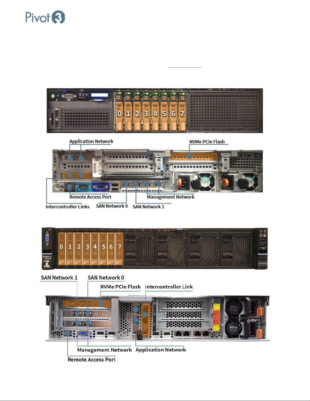
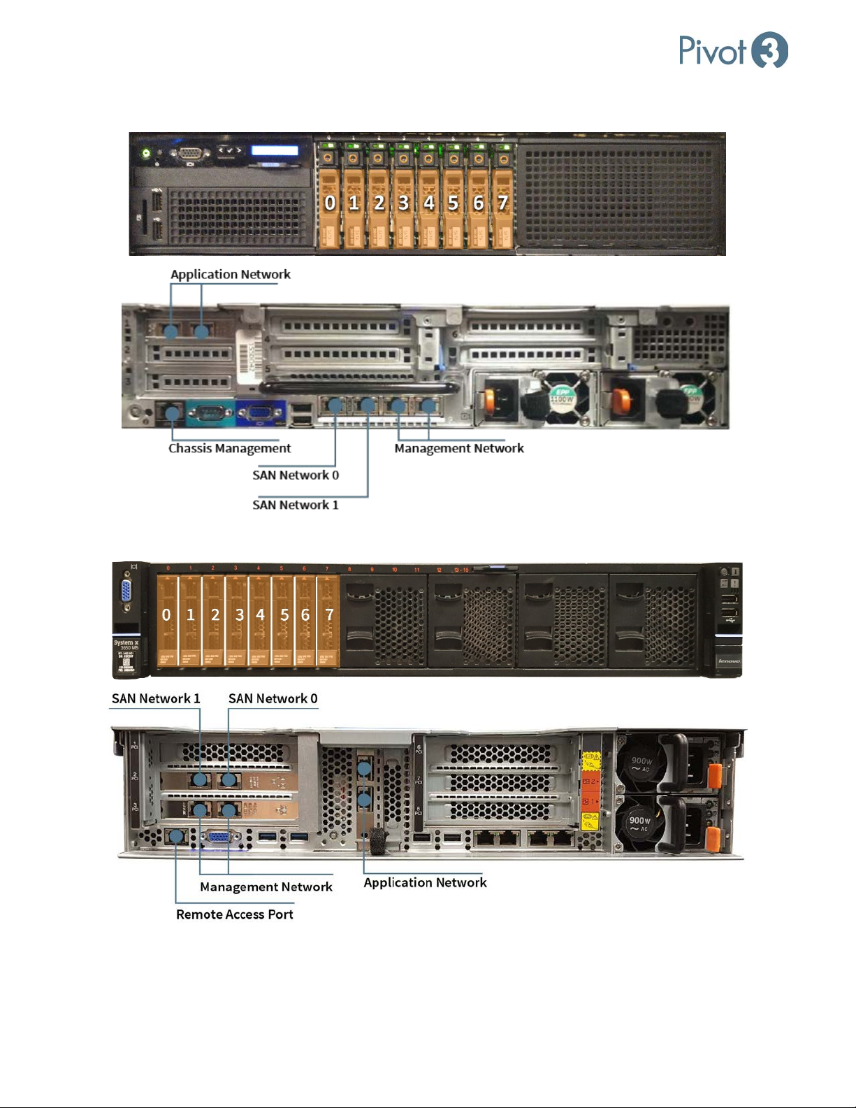
Section 2 Acuity Nodes: Disks & Network Ports
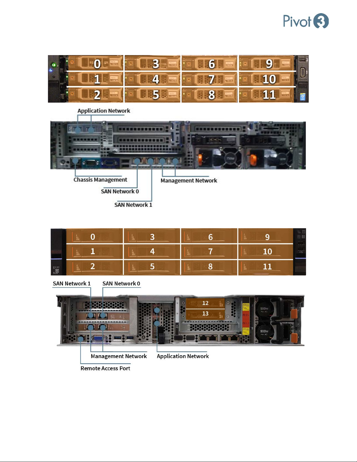
This section describes some of the current Pivot3 hardware configurations, and more items are being added
regularly. For specific information on hardware not listed here, contact Pivot3
X5-6500 (D1) Flash Accelerator Node
.
X5-6500 (L1) Flash Accelerator Node
| 8
DOC-246-GDE-Pivot3 Acuity 2.3 Setup & User Guide-v1.0.docx
Page 9
X-Series Hyperconverged Nodes Powered by Acuity
Setup & User Guide, v1.0
X5-6000 (D1) Flash Standard Node
X5-6000 (L1) Flash Standard Node
9
|
DOC-246-GDE-Pivot3 Acuity 2.3 Setup & User Guide-v1.0.docx
Page 10
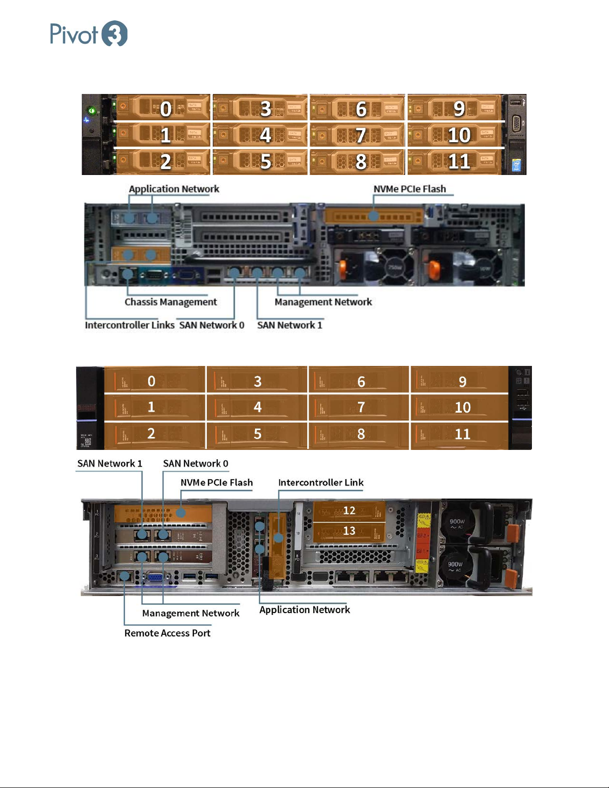
X5-2500 (D1) Hybrid Accelerator Node
X-Series Hyperconverged Nodes Powered by Acuity
Setup & User Guide, v1.0
X5-2500 (L1) Hybrid Accelerator Node
| 10
DOC-246-GDE-Pivot3 Acuity 2.3 Setup & User Guide-v1.0.docx
Page 11
X-Series Hyperconverged Nodes Powered by Acuity
Setup & User Guide, v1.0
X5-2000 (D1) Hybrid Standard Node
X5-2000 (L1) Hybrid Standard Node
11
|
DOC-246-GDE-Pivot3 Acuity 2.3 Setup & User Guide-v1.0.docx
Page 12
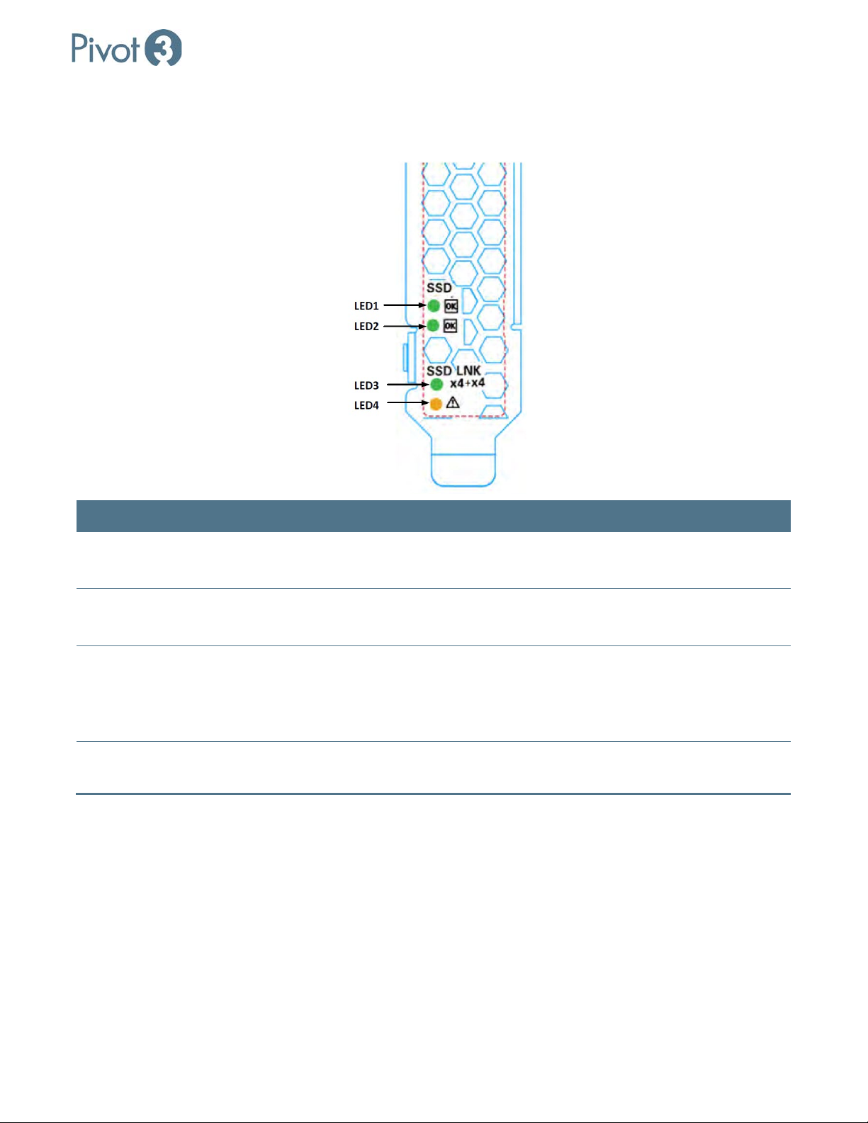
NVMe PCIe Flash LED Status Definitions
On-board LED are provided to indicate the status of the drive.
X-Series Hyperconverged Nodes Powered by Acuity
Setup & User Guide, v1.0
LED Description Blink Behavior
LED 1 – Activity (Green) Shows I/O activity for ASIC1 –
Blinking, Controlled by Firmware
LED2 – Activity (Green)
Shows I/O activity for ASCI2 –
Blinking, controlled by Firmware
LED 3 – Link Behavior Shows link behavior for both
Physical drive controllers
Solid GREEN: No read/write activity.
Blinking GREEN: read/write activity.
Solid GREEN – No read/write activity
Blinking GREEN: read/write activity
Solid GREEN: Link is established and
GEN3 on all 8 lanes
OFF: Link is established, but Gen 1/2 not
using all 8 lanes.
LED 4 – Fault (Yellow) Fault Solid YELLOW: Critical warning or fault
condition.
| 12
DOC-246-GDE-Pivot3 Acuity 2.3 Setup & User Guide-v1.0.docx
Page 13
X-Series Hyperconverged Nodes Powered by Acuity
Setup & User Guide, v1.0
Section 3 Configure ESXi for VMware Access
VMware ESXi is the hypervisor for the Acuity software platforms. As ESXi patches and updates become available,
functionalities may change; patching or updating ESXi past the level recommended for the currently released
Acuity software platform version is a calculated risk. Pivot3 recommends using only the version of ESXi supported
by the current Acuity software platform version.
This section describes how to:
• Configure the Management Network settings for ESXi on new Pivot3 X-Series Nodes
• Allow X-Series nodes to be accessed by VMware management tools
VMware documentation:
More information on getting started with ESXi is available from VMware.
Required items for this section:
• Pivot3 Nodes that have been installed as detailed in Section 1 and are powered on
• A keyboard and monitor or KVM connection to each node
Configure the IP Addresses for the VMware Management Network
The Management Network must be configured before VMware management tools can manage the nodes.
When using DHCP, the IP address is automatically determined and displayed on the console. Make a note of
NOTE:
the IP address assigned and skip to Section 4.
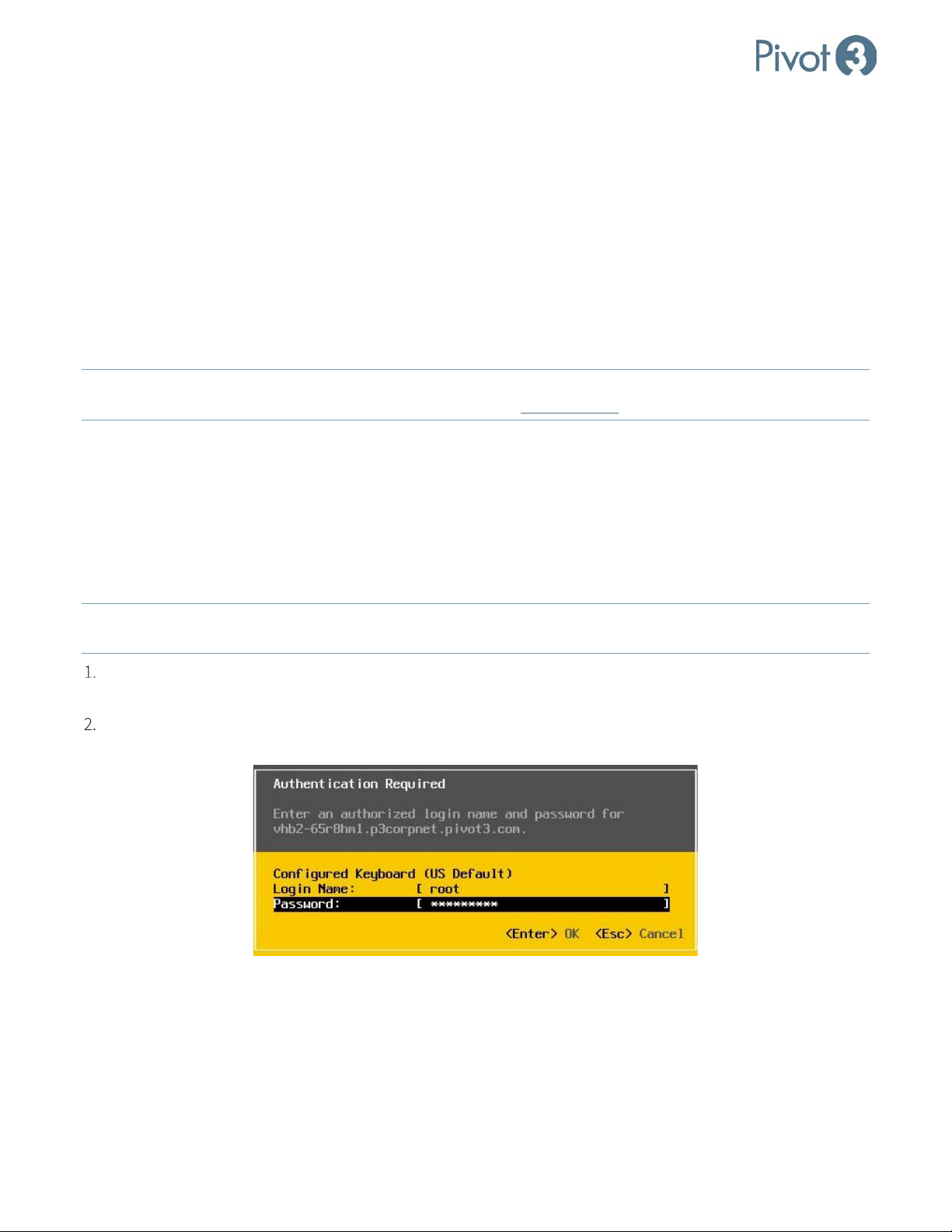
Connect the node to a KVM or connect a keyboard and monitor. The monitor shows the VMware ESXi direct
console.
Press <F2> to login to the ESXi console. The default user name is root and the default password is
vSphereP3. Press <Enter>.
13
|
DOC-246-GDE-Pivot3 Acuity 2.3 Setup & User Guide-v1.0.docx
Page 14
X-Series Hyperconverged Nodes Powered by Acuity
Setup & User Guide, v1.0
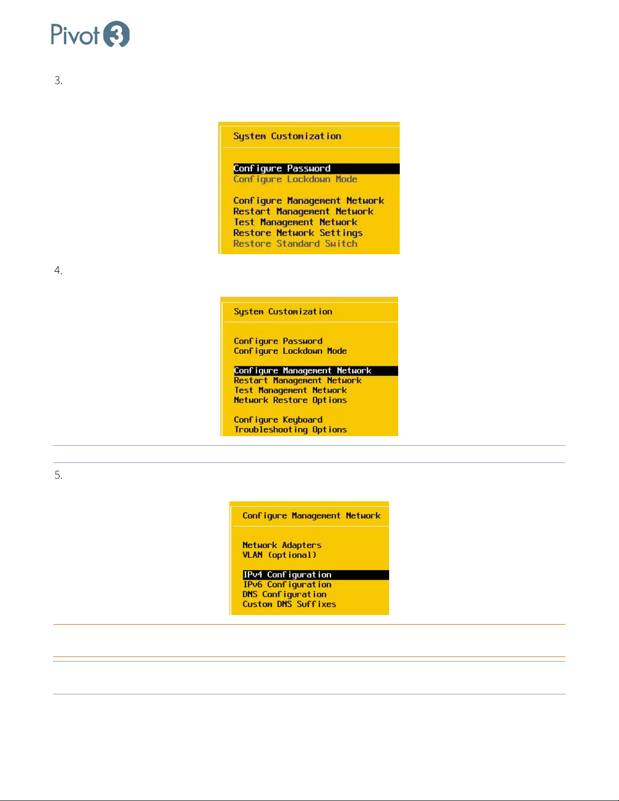
ESXi displays the System Customization screen. (Password can be configured whenever it is convenient.
Remember to make a note of Administrator credentials when set. User name and password can be reset, but
credentials will not be recoverable if lost or forgotten.)
Use the up and down arrow keys on the keyboard to highlight Configure Management Network. Press
<Enter>.
NOTE: To configure the host using SSH, enable SSH in this menu from Troubleshooting Options
.
On the Configure Management Network screen, use the up and down arrow keys on the keyboard to
highlight IPv4 Configuration. Press <Enter>.
CRITICAL:
Ensure that the chosen Network Adapter is the correct one. Default is Adapter 2, but may vary in the local
environment setup.
NOTE: Ensure that, if the management port is a trunk port, the management VLAN has been entered and tagged on
the menu. Trunk ports cannot accept a native VLAN that is identical to the management VLAN.
| 14
DOC-246-GDE-Pivot3 Acuity 2.3 Setup & User Guide-v1.0.docx
Page 15
X-Series Hyperconverged Nodes Powered by Acuity
Setup & User Guide, v1.0
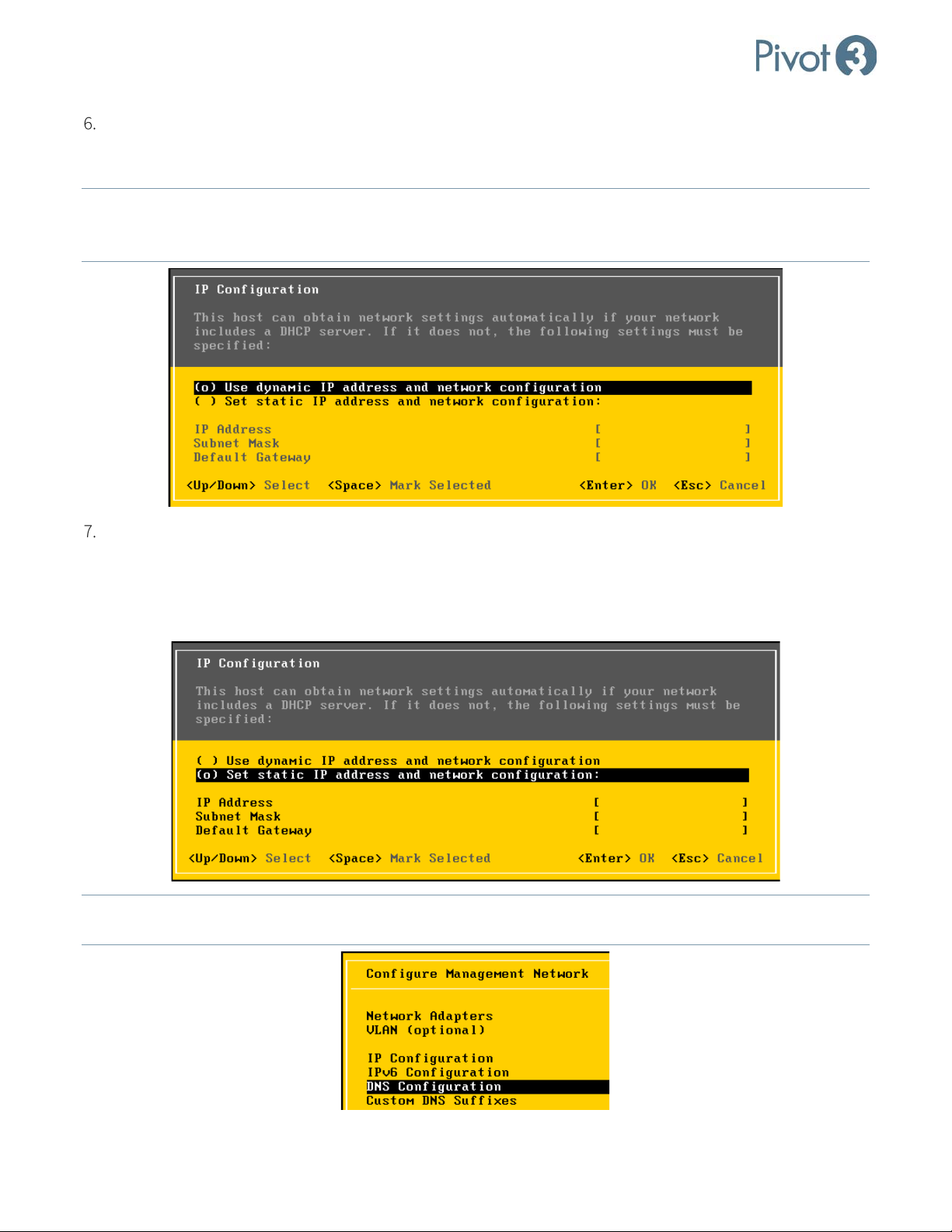
If there is a DHCP server on the VMware Management Network, select the top option in the display dialog, Use
dynamic IP address & network configuration. The values for IP Address, Subnet Mask, and Default
Gateway will be set dynamically by the DHCP server. Make a note of the IP address for this host.
NOTE: If using Use dynamic IP address & network configuration,
ensure that the IP address of the ESXi host does
not change on reboot. If the host IP changes on reboot, VMware management tools will not be able to
auto-connect to the ESXi host.
If there is not a DHCP server on the VMware Management Network, the values for IP Address, Subnet Mask,
and Default Gateway must all be manually entered. Select the second option on the display console, Set
static IP address and network configuration, and complete the manual entry of values for IP Address,
Subnet Mask, and Default Gateway. Make a note of this host’s IP address. Once completed, press <Enter> to
return to the Configure Management Network screen.
NOTE: If the VMware Management Network is using DNS, on the Configure Management Network
DNS Configuration. Press <Enter>.
15
|
DOC-246-GDE-Pivot3 Acuity 2.3 Setup & User Guide-v1.0.docx
screen, select
Page 16
X-Series Hyperconverged Nodes Powered by Acuity
Setup & User Guide, v1.0
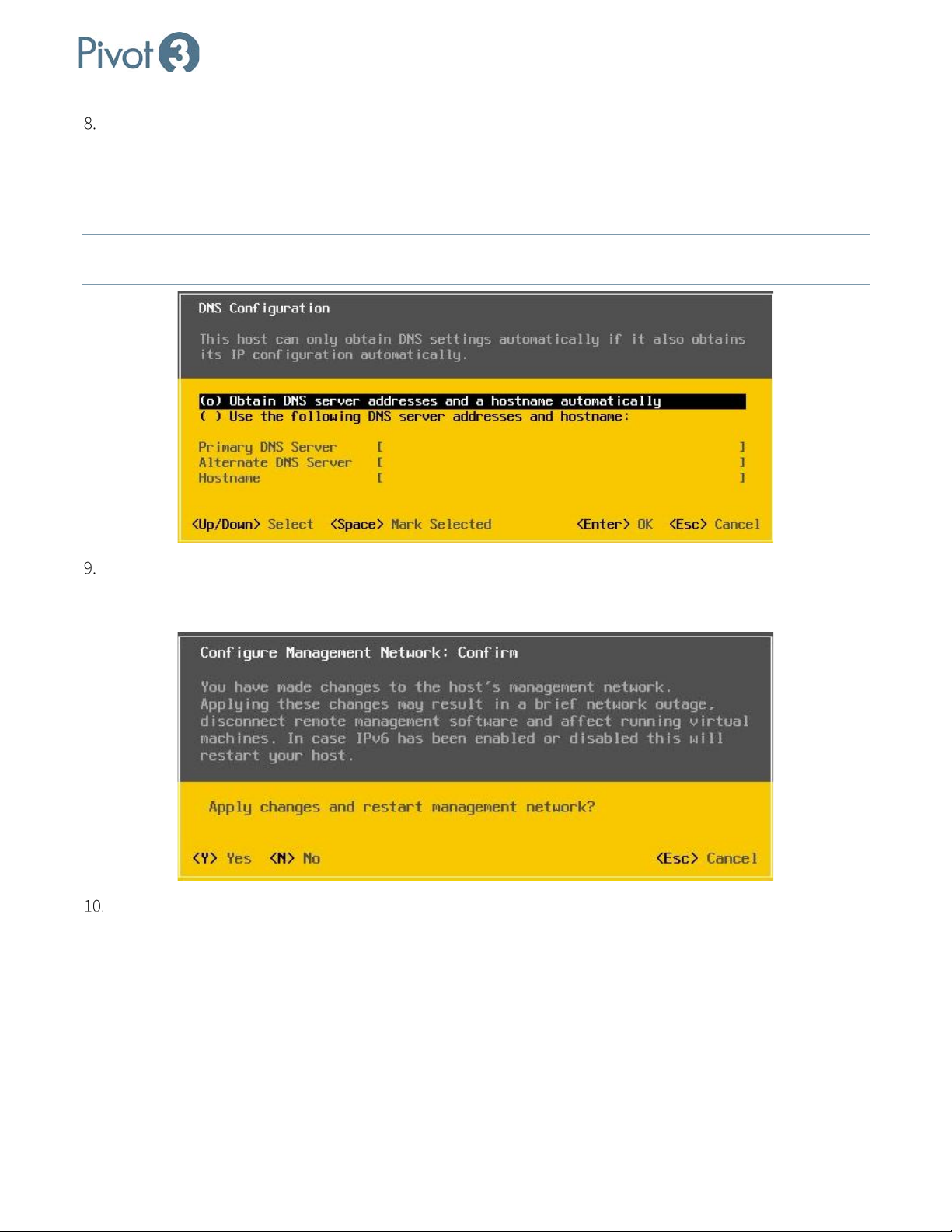
With a choice of Obtain DNS server addresses and a hostname automatically, the selection task will be
completed automatically. Simply press the Enter key to move through this screen. The other available option,
Use the following DNS server addresses and hostname, requires that the information be entered manually
and connected to host name that is unique on the network. Once complete, press <Enter> to return to the
Configure Management Network screen.
NOTE: For vCenter to communicate with the host, the hostname must be resolvable on the network
from vCenter,
ESXi host in cluster, client PC, and any 3rd party tool that references the host by hostname.
Press <Esc> to return to the System Customization screen. If any changes were made to the Management
Network settings, a confirmation prompt will appear. Press <Y> to apply the changes and restart the
management network.
Repeat Steps 1-8 for each node.
| 16
DOC-246-GDE-Pivot3 Acuity 2.3 Setup & User Guide-v1.0.docx
Page 17
X-Series Hyperconverged Nodes Powered by Acuity
Setup & User Guide, v1.0
Configure SSH
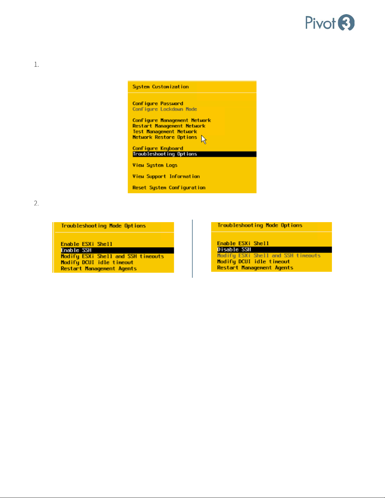
To Enable or Disable SSH, log in to the main ESXi screen and use the arrow keys to navigate to
Troubleshooting Options. Press Enter to select.
The SSH option provided will differ depending on whether SSH has already been enabled on this machine.
Enter to activate the desired state and press Esc to exit the dialog.
Press
17
|
DOC-246-GDE-Pivot3 Acuity 2.3 Setup & User Guide-v1.0.docx
Page 18
X-Series Hyperconverged Nodes Powered by Acuity
Section 4 Install Plugin for Windows
Before the installation procedure begins, ensure the following items are easily accessible:
• vCenter Server IP address
• Plugin installation package from Pivot3
• Administrator credentials for each host
• Email addresses of all known administrators
Setup & User Guide, v1.0
NOTE: The Pivot3 vCenter Plugin is only compatible with the vSphere Web Client
installable VMware vSphere software client.
CRITICAL: For full functionality, ensure all Pivot3 nodes managed by the Plugin are included in the vCenter inventory.
. It is not compatible with the
Download and Open Plugin Executable
Download the file Pivot3_vCenter_Plugin_10.3.x.xxx.exe received from Pivot3 Support to the Management
Station. Double-click the .exe file to open the file and begin the process.
NOTE: To request a Pivot3 vCenter Plugin installation file, send a request
through the Support Portal.
Follow Installation Wizard
The Installation Wizard for the vCenter plugin is designed to be intuitive and user-friendly. This section will
explain the steps, though most of the installation process will seem familiar.
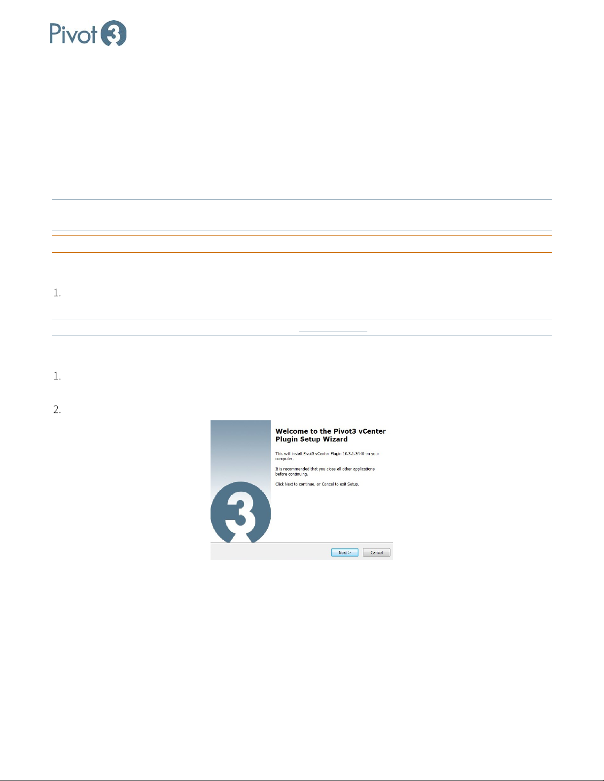
When the splash screen appears, click Next. (Pivot3 Acuity version may differ.)
| 18
DOC-246-GDE-Pivot3 Acuity 2.3 Setup & User Guide-v1.0.docx
Page 19
X-Series Hyperconverged Nodes Powered by Acuity
Setup & User Guide, v1.0
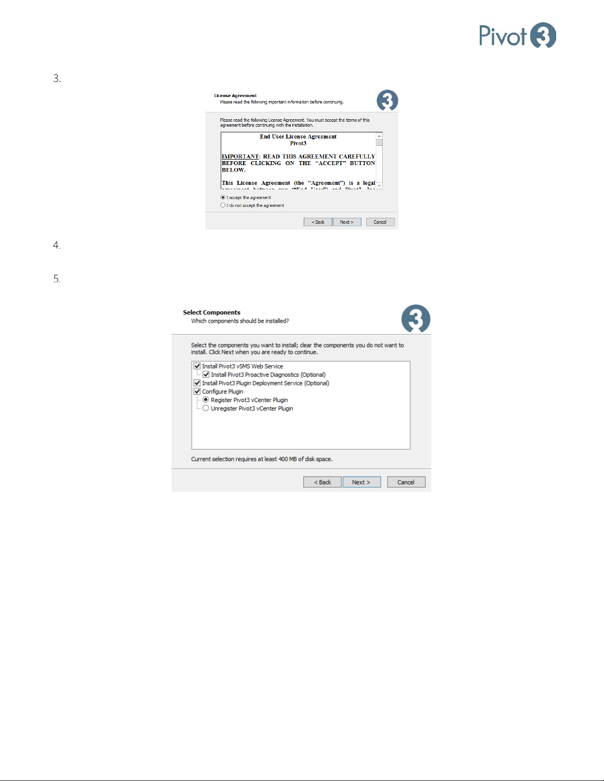
Read and accept the End User License Agreement. Click Next.
Read the information about Pivot3 Proactive Diagnostics and the Pivot3 Plugin Deployment Service, then
press Next.
Select the components to be installed. Configure Plugin, if checked, will take steps to register the plugin
without further intervention. It is recommended to install all components as shown.
19
|
DOC-246-GDE-Pivot3 Acuity 2.3 Setup & User Guide-v1.0.docx
Page 20
X-Series Hyperconverged Nodes Powered by Acuity
Setup & User Guide, v1.0
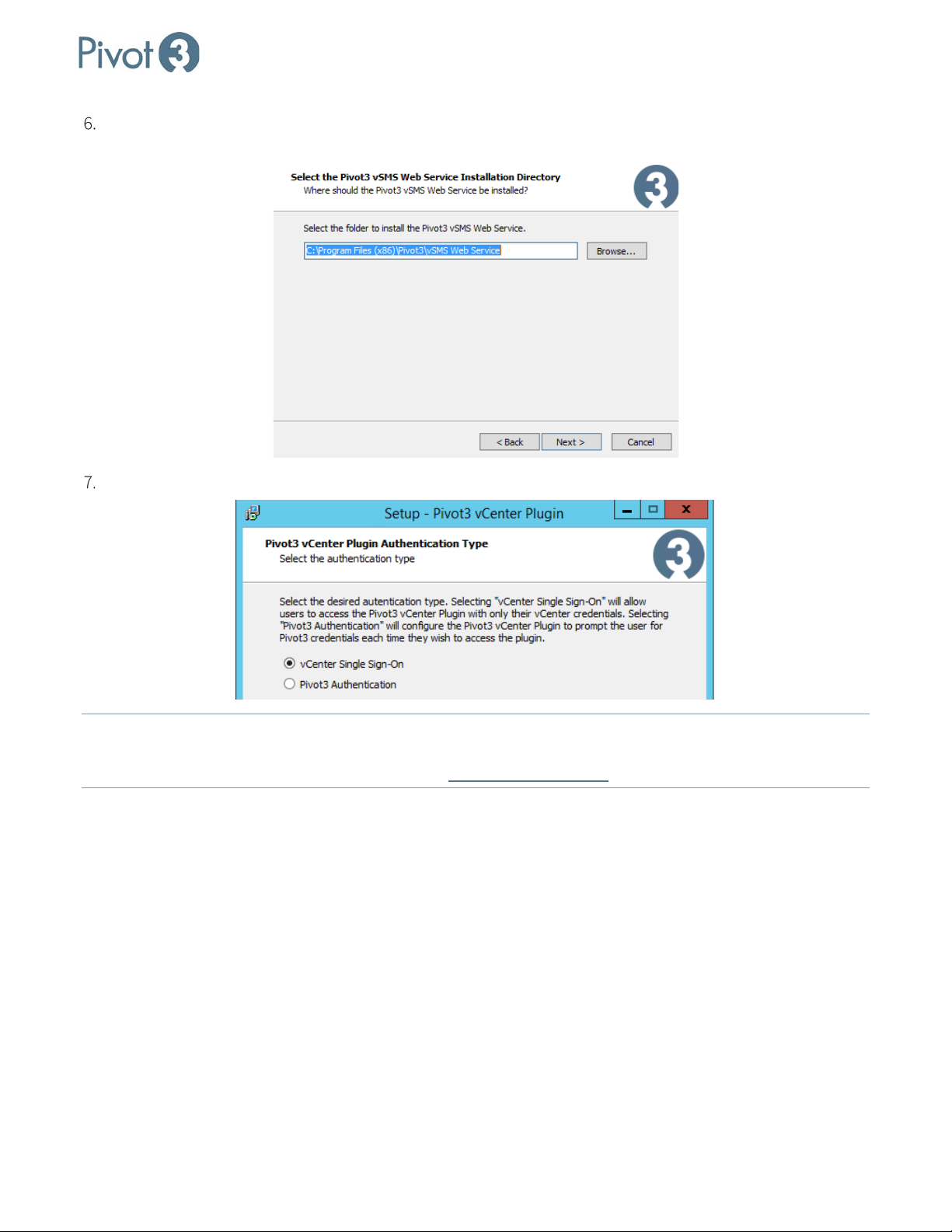
Select the directory to install the web server. If the default location is not preferred, use the Browse function
to navigate to a desired location.
Choose the desired authentication type between vCenter Single Sign-On or Pivot3 Authentication.
NOTE: vCenter Single Sign-On
Pivot3 Authentication requires Pivot3 credentials to also be entered for each login. For more information on
the vCenter Single Sign-On feature, consult the Pivot3 Support Portal
will allow the user to access the Pivot3 vCenter Plugin with vCenter credentials only;
.
| 20
DOC-246-GDE-Pivot3 Acuity 2.3 Setup & User Guide-v1.0.docx
Page 21
X-Series Hyperconverged Nodes Powered by Acuity
Setup & User Guide, v1.0
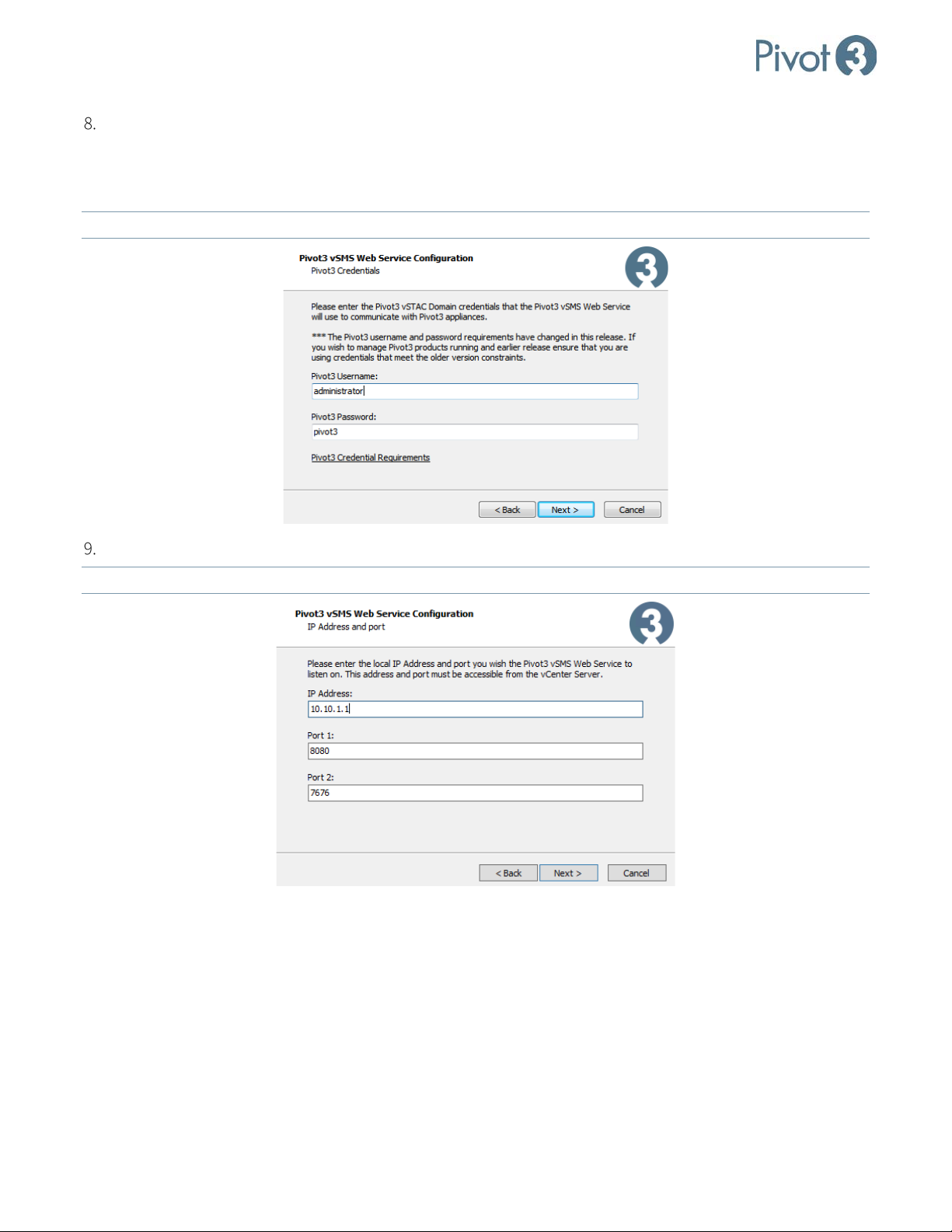
Enter the Administrator credentials to be used on the web server determined in Step 6. Even for Single Sign-
On setup, Pivot3 credentials still need to be entered here. The default username for Single Sign-On is
pivot3ssouser, and the password can be custom-set. The default Single Sign-On username cannot be
changed; only the password can be modified.
NOTE: For this step, the password will not be obscured, so ensure all credentials are accurate before clicking Next
Enter the local IP address and port for the vSMS Web Server to listen on.
NOTE: The address and port must be accessible from the vCenter Server.
.
21
|
DOC-246-GDE-Pivot3 Acuity 2.3 Setup & User Guide-v1.0.docx
Page 22
X-Series Hyperconverged Nodes Powered by Acuity
Setup & User Guide, v1.0
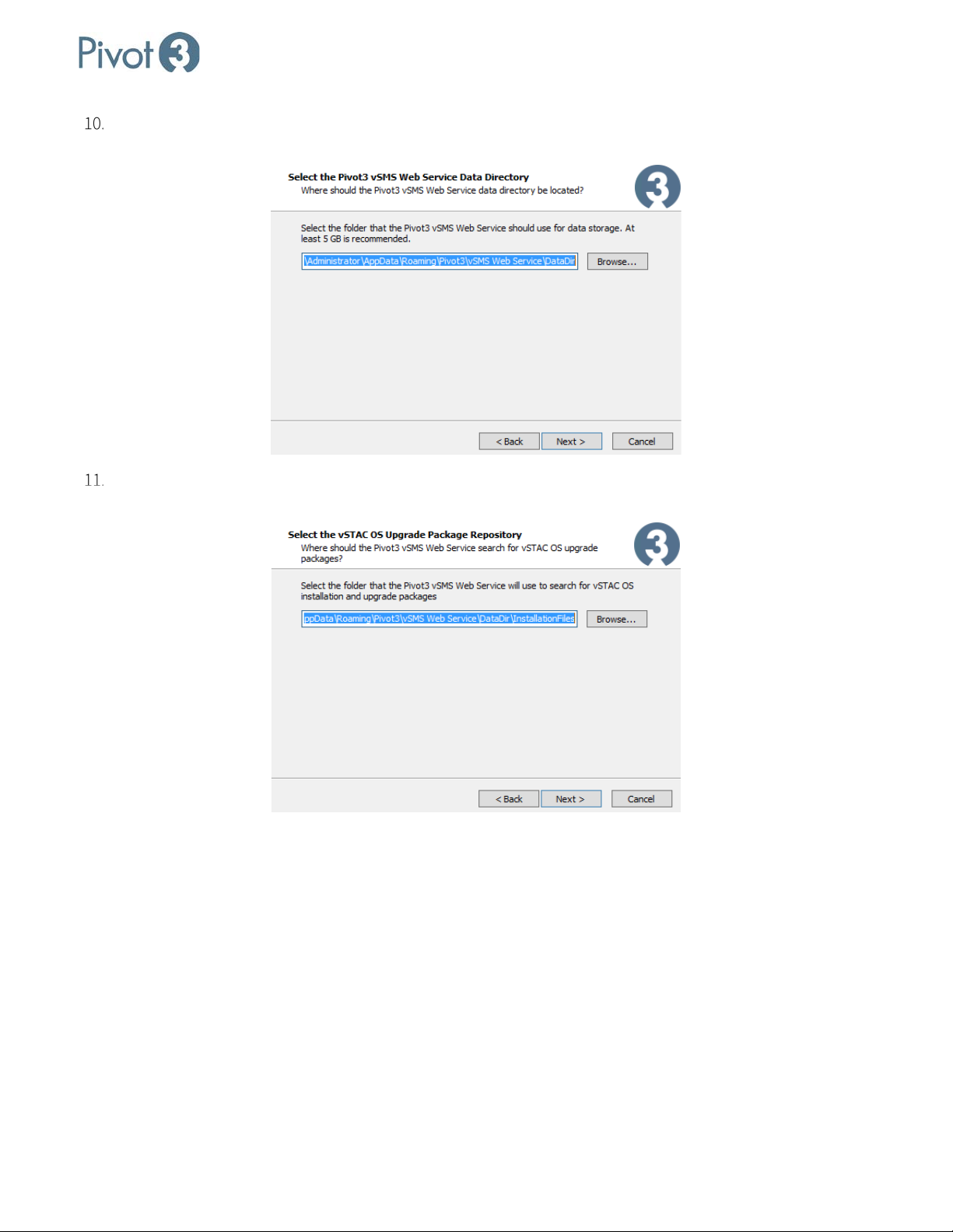
Select the folder that the plugin should use as a local data storage repository for temporary files. If the default
location is acceptable,
make a note of this location for future reference.
Select the file folder to host the Acuity software files. This will also be the folder that will hold upgrade files
once they are received from Support, so
keep a record of this location.
| 22
DOC-246-GDE-Pivot3 Acuity 2.3 Setup & User Guide-v1.0.docx
Page 23
X-Series Hyperconverged Nodes Powered by Acuity
Setup & User Guide, v1.0
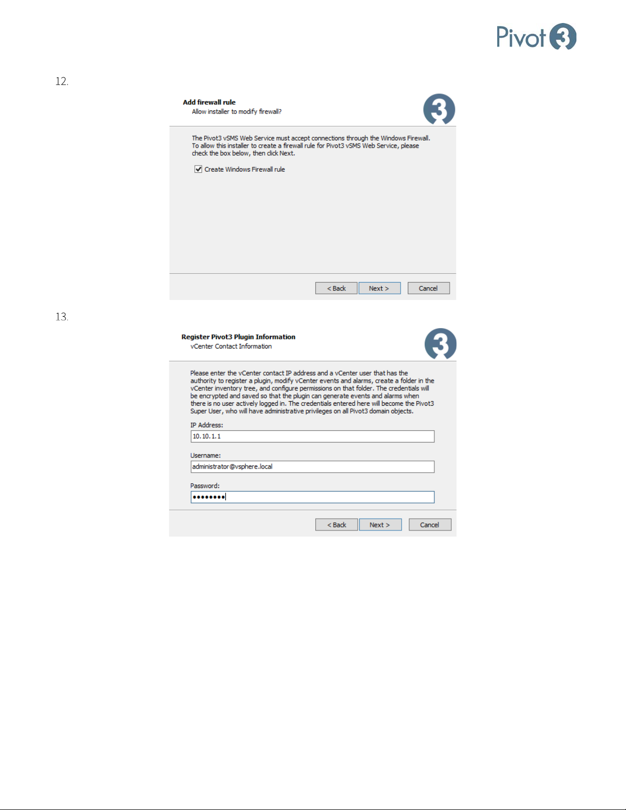
Click the check box or verify that the box is checked to Create a Windows Firewall rule.
Enter the vCenter server contact IP address and the vCenter credentials to be used for that IP.
23
|
DOC-246-GDE-Pivot3 Acuity 2.3 Setup & User Guide-v1.0.docx
Page 24
X-Series Hyperconverged Nodes Powered by Acuity
Setup & User Guide, v1.0
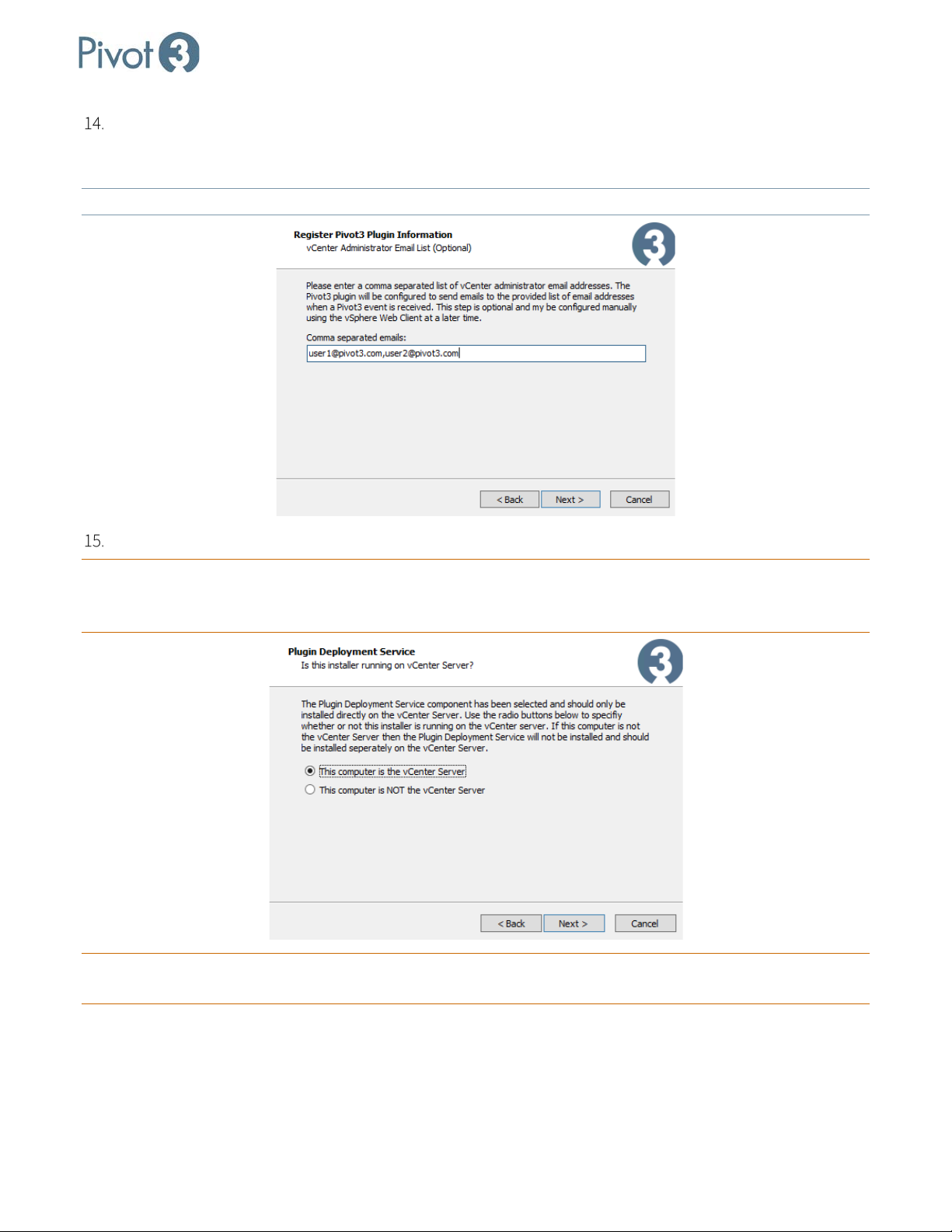
For the contact IP address and vCenter credentials set up in the previous step, enter a comma-separated list
of email addresses for the vCenter administrators who are authorized to receive emails from Pivot3 and the
Pivot3 plugin.
NOTE: The email addresses provided here will also control who receives alarm notifications.
Choose the appropriate radio button for the local setup and click Next.
CRITICAL: If the option This computer is NOT the vCenter Server is chosen,
not install. A successful deployment installation will require setup beginning at Step 2 of this section on
the vCenter server’s Management Station
.
the plugin’s deployment service will
CRITICAL: For full Pivot3 functionality,
reboot.
| 24
DOC-246-GDE-Pivot3 Acuity 2.3 Setup & User Guide-v1.0.docx
a fresh login to vSphere Web Client is required after each vCenter server
Page 25
X-Series Hyperconverged Nodes Powered by Acuity
Setup & User Guide, v1.0
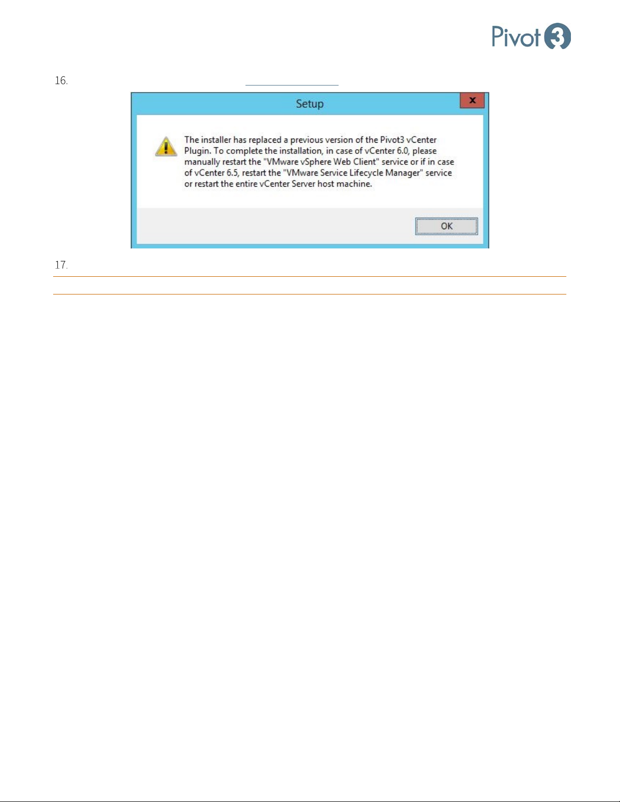
After upgrading, it will be necessary to clear browser cache before logging back in to the vSphere Web Client.
Confirm the settings in the final setup box. When ready, click Install to complete setup and install plugin.
CRITICAL:
This will require the web portion of the vCenter server to be restarted.
25
|
DOC-246-GDE-Pivot3 Acuity 2.3 Setup & User Guide-v1.0.docx
Page 26
X-Series Hyperconverged Nodes Powered by Acuity
Section 5 Install Plugin for Linux
Before You Start
Before the installation procedure begins, ensure the following items are easily accessible:
• vCenter Server IP address
• Plugin installation package from Pivot3
• Administrator credentials for each host
• Email addresses of all known administrators
Setup & User Guide, v1.0
NOTE: The Pivot3 vCenter Plugin is only compatible with the vSphere Web Client
installable VMware vSphere software client.
. It is not compatible with the
Download and Open Plugin Package
Download the file Pivot3_vCenter_Plugin_10.3.1.[####].tar.gz received from Pivot3 Support to the
Management Station. (For the purposes of this document, [####] stands for the build number and may vary.)
CRITICAL:
NOTE: To obtain a Pivot3 vCenter Plugin installation file, send a request through the Support Portal.
CRITICAL: To install the plugin on a Linux vCenter from a Windows client, WinSCP and PuTTY clients will be
For full functionality, ensure all Pivot3 nodes managed by the Plugin are included in the vCenter inventory.
required.
Prepare Environment
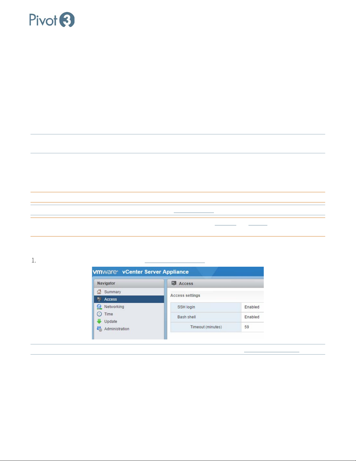
Enable bash and SSH on Linux vCenter (https://vCenterIP:5480).
NOTE: For any issues opening the connection to Linux vCenter using WinSCP, consult VMware KB 2107727
| 26
DOC-246-GDE-Pivot3 Acuity 2.3 Setup & User Guide-v1.0.docx
.
Page 27
X-Series Hyperconverged Nodes Powered by Acuity
Setup & User Guide, v1.0
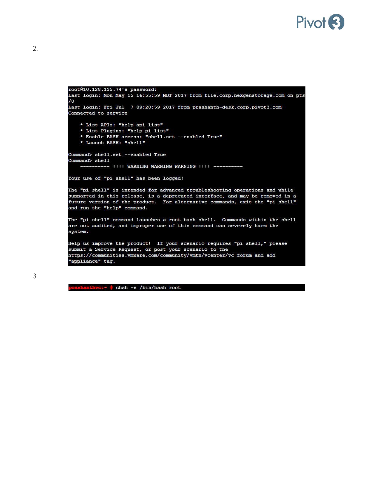
Using PuTTY, open an SSH session to Linux vCenter. After the connection is completed, enable shell by using
the following commands:
Command> shell.set --enabled True
Command> shell
Then use the command # chsh -s /bin/bash root
27
|
DOC-246-GDE-Pivot3 Acuity 2.3 Setup & User Guide-v1.0.docx
Page 28

X-Series Hyperconverged Nodes Powered by Acuity
Setup & User Guide, v1.0
Open WinSCP and connect to Linux vCenter. Drag the Pivot3_vCenter_Plugin_10.3.1.[####].tar.gz file to
the default directory of vCenter as shown below.
Return to the Appliance Shell by running the following command:
# chsh -s /bin/appliancesh root
Format and extract the .tar file and list directory contents at the command prompt as follows:
Localhost:~ # ls
Multiple files will be listed. Ensure Pivot3_vCenter_Plugin_10.3.1.[####].tar.gz is one of them.
| 28
DOC-246-GDE-Pivot3 Acuity 2.3 Setup & User Guide-v1.0.docx
Page 29
X-Series Hyperconverged Nodes Powered by Acuity
Setup & User Guide, v1.0
CRITICAL: If Pivot3_vCenter_Plugin_10.3.0.####.tar.gz does not show up in this list command, begin the process
again from Step 4 of this section.
Create a new directory so that the file has a fresh location to extract to:
Localhost:~# mkdir plugin10.3.1.xx
Navigate to the new directory created for file extraction:
Localhost:~# cd tmp/
Now that the Plugin installer file has been correctly placed and identified, open the .tar.gz file as follows:
localhost:~# tar xvf Pivot3_vCenter_Plugin_10.3.1.[####].tar.gz
List directory contents once more to ensure the files p3vcenterplugin-installer.sh and P3VMwarePlugin-
10.3.1.xx.zip have been extracted.
Change the permissions for the installation file to make it executable:
localhost:~# chmod 777 p3vcenterplugin-installer.sh
Run the installation file and answer the wizard’s questions as prompted with desired information:
Localhost:~# ./p3vcenterplugin-installer.sh
At this point, the Linux CLI installation aligns closely with the Windows installation options. For each question,
choose the desired variables to enter for each of the information requests:
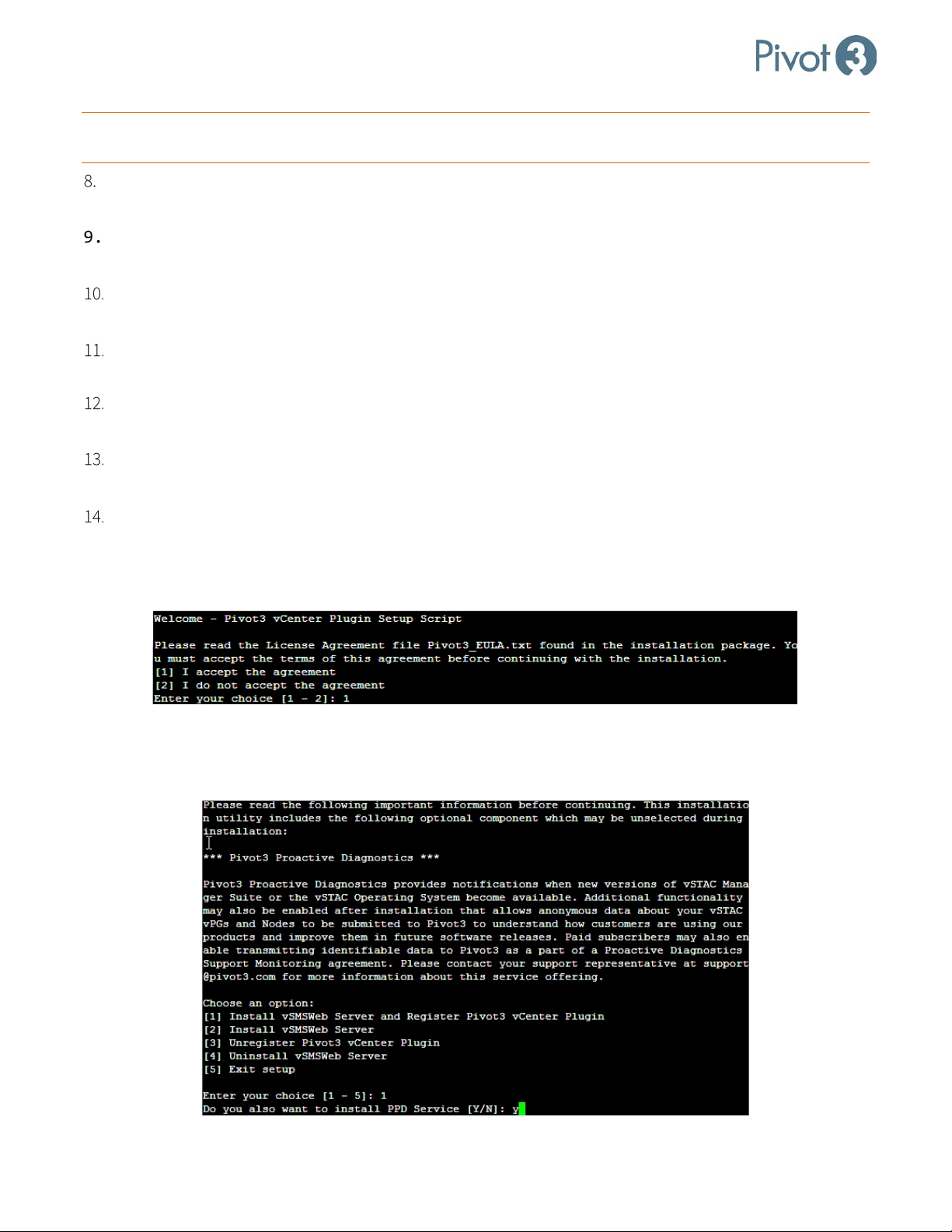
a. Read the License Agreement file Pivot3_EULA.txt that was sent with the installation package. To accept
the License Agreement, press 1.
b. Read the Pivot3 Proactive Diagnostics blurb, and press 1 to install vSMS Web Server and Register Pivot3
vCenter Plugin.
c. Press Y to install PPD Service.
29
|
DOC-246-GDE-Pivot3 Acuity 2.3 Setup & User Guide-v1.0.docx
Page 30
X-Series Hyperconverged Nodes Powered by Acuity
Setup & User Guide, v1.0
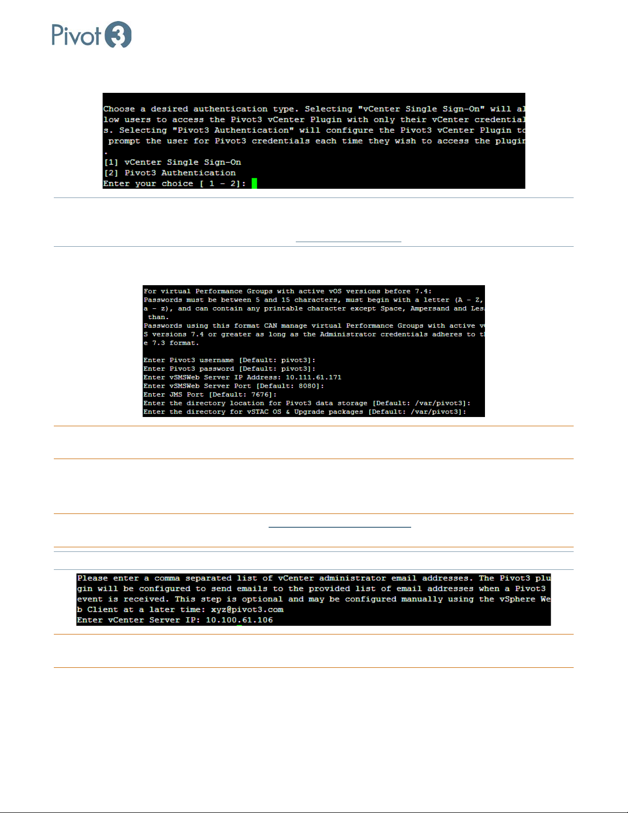
d. Choose an authentication type between vCenter Single Sign-On and Pivot3 Authentication.
NOTE: vCenter Single Sign-On
will allow the user to access the Pivot3 vCenter Plugin with vCenter credentials only;
Pivot3 Authentication requires Pivot3 credentials to also be entered for each login. For more information on
the vCenter Single Sign-On feature, consult the Pivot3 Support Portal
.
e. Continue following the wizard prompts, entering the desired strings to answer each question. For many
questions, the default values are listed; to accept the default values, simply press Enter.
CRITICAL: The vSMS IP and the vCenter Server IP will most likely be the IP of the
currently connected vCenter
Virtual Appliance, unless vCenter services have been split between separate servers.
f. For the contact IP address and vCenter credentials set up in the previous step, enter a comma-separated
list of email addresses for the vCenter administrators who are authorized to receive emails from Pivot3
and the Pivot3 plugin.
CRITICAL: The vCenter credentials will either be [email protected]
or a service account set up in
vCenter with an Administrator Role.
NOTE: The email addresses provided here will also control who receives alarm notifications.
CRITICAL: If SSO Authentication has been chosen, the Pivot3 username entered must be pivot3ssouser
coded and cannot be changed.
| 30
DOC-246-GDE-Pivot3 Acuity 2.3 Setup & User Guide-v1.0.docx
. This is hard-
Page 31
X-Series Hyperconverged Nodes Powered by Acuity
Setup & User Guide, v1.0
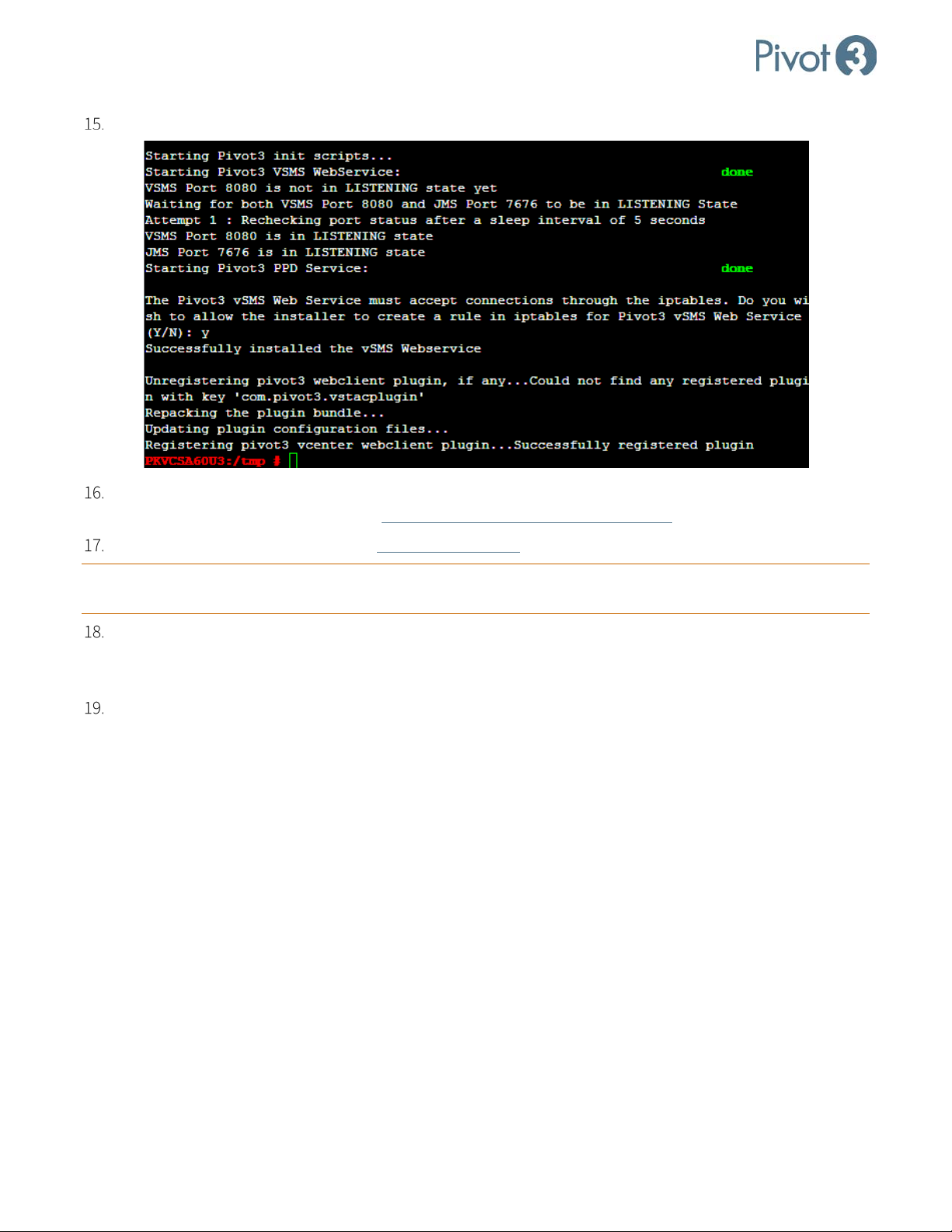
At the final question, enter Y to allow the installer to create a rule in iptables for Pivot3 vSMS Web Service.
If upgrading, it will be necessary to restart the vSphere Web Client Service or reboot the vCenter. For more
information on this procedure, consult
VMware Knowledge Base Article 2109887.
After upgrading, it will be necessary to clear browser cache before logging back in to the vSphere Web Client.
CRITICAL: For full Pivot3 functionality, a fresh login to vSphere Web Client is required after each vCenter server
reboot.
To reset the vCenter after installing the Linux plugin for Linux vCSA 6.0, use service vsphere-client
restart. For Linux vCSA 6.5, use the commands service-control --stop vsphere-client and then
service-control --start vsphere client.
At this point, installation is complete. Log in to the vSphere Web Client and continue to Section 6.
31
|
DOC-246-GDE-Pivot3 Acuity 2.3 Setup & User Guide-v1.0.docx
Page 32
X-Series Hyperconverged Nodes Powered by Acuity
Setup & User Guide, v1.0
Section 6 Network Fine Tuning
There are a few procedures that need to be performed before the Acuity software platform can be considered
optimally configured. These represent best practices for any X-Series Acuity environment.
Time Synchronization
With the Acuity software platform, time synchronization between vCenter nodes, Host Servers, and VMs is critical
for proper functionality of features such as scheduled tasks. NTP should be configured for the vCenter Server
Appliance, the ESXi Nodes, external host servers, and VMs to ensure that all are synchronized.
CRITICAL:
Ensure all ESXi hosts are configured to sync via NTP.
vCenter Server & External Host Servers in Windows
Configuration Process
# Configuration Task Procedure Details / Expected Results
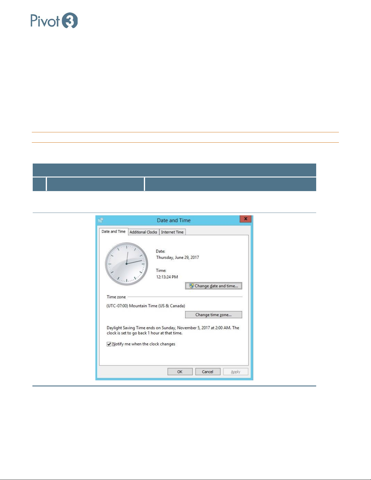
Change date and time settings on
1
Server
Click on the time at the bottom right corner of the vCenter
Server Windows UI.
| 32
DOC-246-GDE-Pivot3 Acuity 2.3 Setup & User Guide-v1.0.docx
Page 33
X-Series Hyperconverged Nodes Powered by Acuity
Setup & User Guide, v1.0
Configuration Process
# Configuration Task Procedure Details / Expected Results
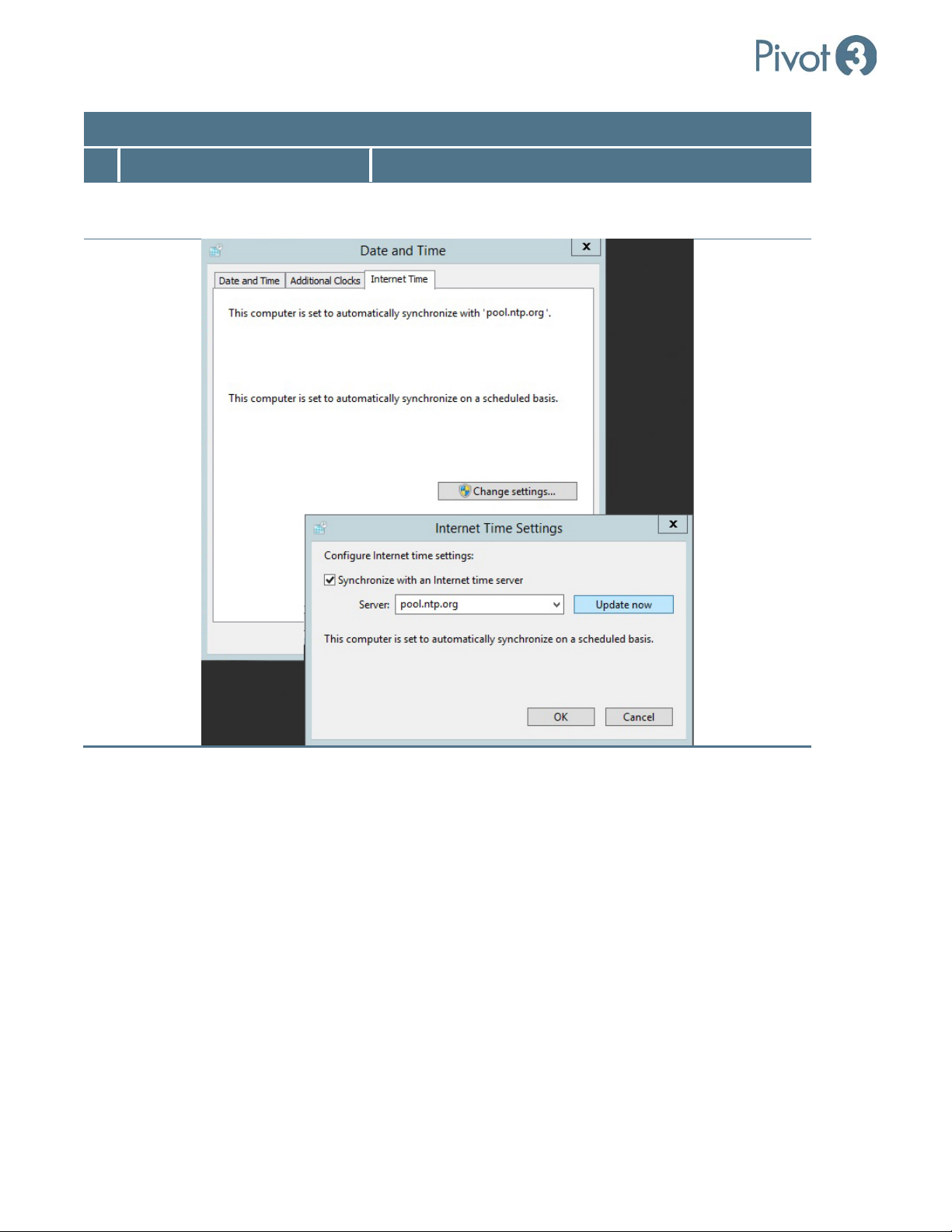
2 Sync with NTP Internet Time > Change Settings > Synchronize with an
Internet time server > pool.ntp.org
33
|
DOC-246-GDE-Pivot3 Acuity 2.3 Setup & User Guide-v1.0.docx
Page 34
X-Series Hyperconverged Nodes Powered by Acuity
2
vCenter Server & External Host Servers in Linux
Configuration Process
# Configuration Task Procedure Details / Expected Results
Setup & User Guide, v1.0
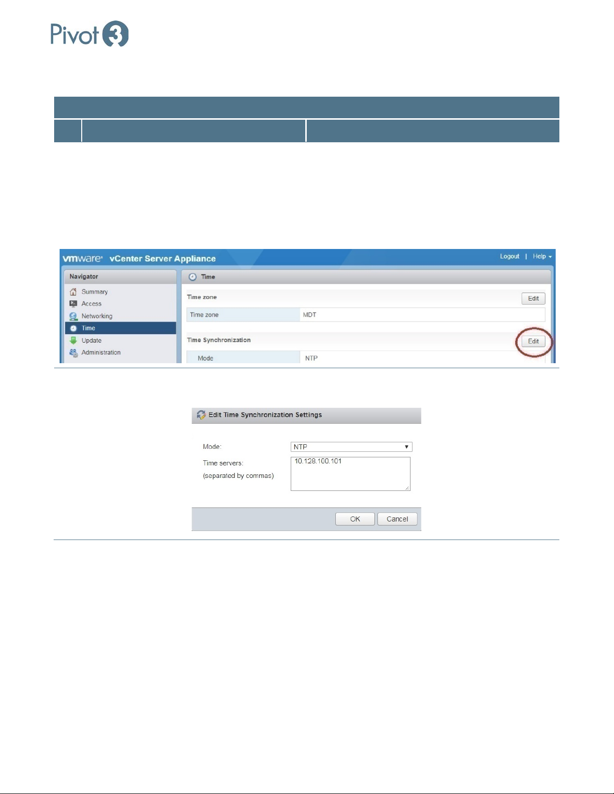
1 Edit time synchronization settings.
(i.e., [vCenterIP]:5480)
In a web browser, connect to the IP address of the
Linux vCenter on port 5480.
Log in with an account that has administrative
privileges.
Navigate to the Time settings page.
In the Time Synchronization box, click Edit.
Set Mode. Select NTP from the Mode pulldown and enter
pool.ntp.org in the Time Servers box. Click OK.
| 34
DOC-246-GDE-Pivot3 Acuity 2.3 Setup & User Guide-v1.0.docx
Page 35
X-Series Hyperconverged Nodes Powered by Acuity
Setup & User Guide, v1.0
ESXi Nodes
Configuration Process
# Configuration Task Procedure Details / Expected Results
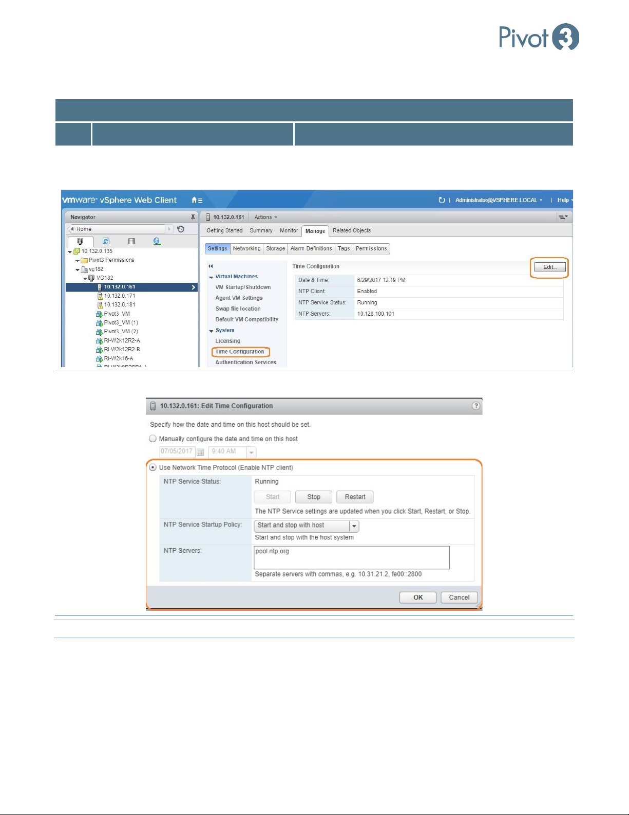
1
Set up Time Configuration in Acuity ESXi
Host > Settings tab > Time Configuration > Edit
nodes
2 Enable NTP NTP Client Enabled > Options
NOTE: This must be done on each ESXi node.
35
|
DOC-246-GDE-Pivot3 Acuity 2.3 Setup & User Guide-v1.0.docx
Page 36
X-Series Hyperconverged Nodes Powered by Acuity
Sync VMs with Host Upon Creation (Recommended)
Configuration Process
# Configuration Task Procedure Details / Expected Results
Setup & User Guide, v1.0
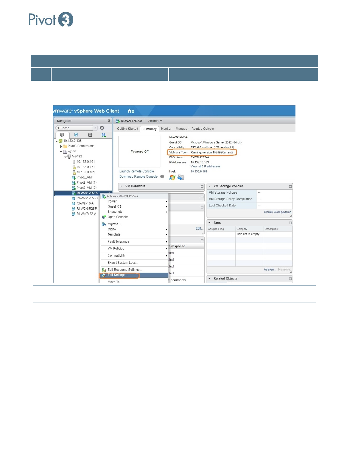
1 Synchronize guest time with host
Create VM > Ensure VMware Tools are Installed >
Right-click VM > Edit Settings…
NOTE: VMware tools are not installable on the Pivot3 VM directly
noting that “VMware Tools are not installed on this virtual machine” can be disregarded.
| 36
DOC-246-GDE-Pivot3 Acuity 2.3 Setup & User Guide-v1.0.docx
. This is expected behavior; any error messages
Page 37
X-Series Hyperconverged Nodes Powered by Acuity
Setup & User Guide, v1.0
Configuration Process
# Configuration Task Procedure Details / Expected Results
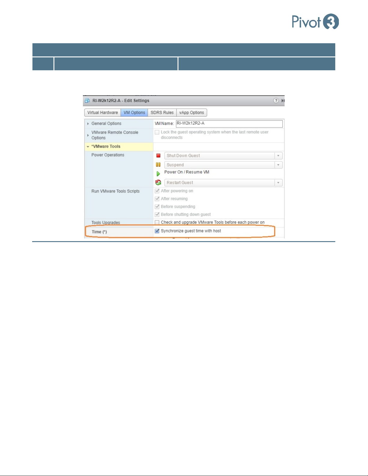
2 Activate synchronization option VM Options tab > Synchronize guest time with host >
OK
37
|
DOC-246-GDE-Pivot3 Acuity 2.3 Setup & User Guide-v1.0.docx
Page 38
X-Series Hyperconverged Nodes Powered by Acuity
Setup & User Guide, v1.0
Section 7 Navigating the Plugin
Log In to vSphere Web Client
In a preferred web browser, navigate to the IP address of the server hosting vCenter and log in to the vSphere
Web Client.
NOTE: Microsoft Internet Explorer is not recommended; Google Chrome or Mozilla Firefox seem to offer a
smoother plugin experience.
NOTE: To prevent sync issues, Pivot3 recommends only using a single management utility (one vSMS or one Pivot3
Plugin) to configure the domain. Multiple users can be logged in simultaneously, but only one plugin or client
should manage the entire domain.
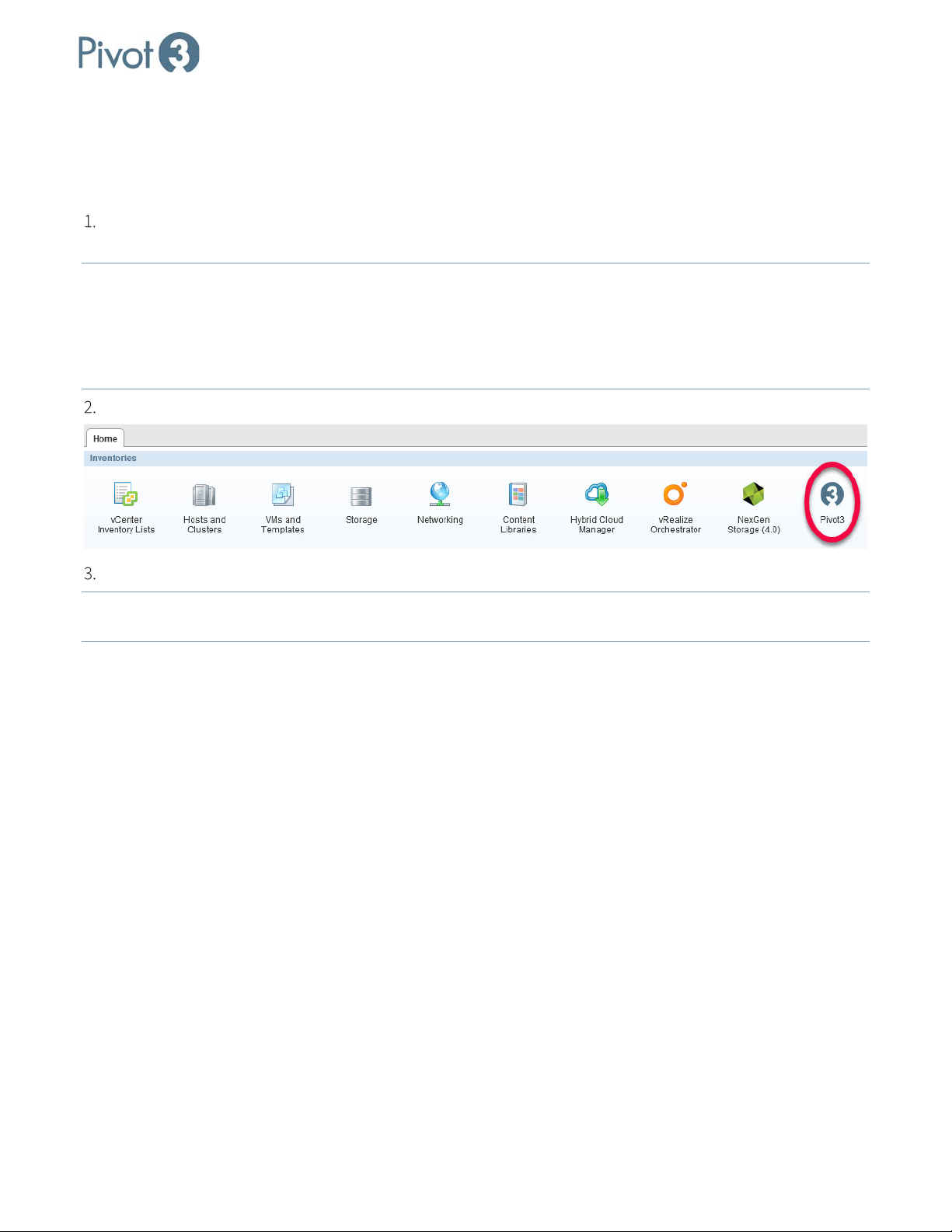
Click the Pivot3 icon located in the Inventories section of the Home tab as shown below.
Log in with the same Pivot3 credentials entered in Section 3, Step 8.
NOTE:
If Single Sign-On was configured during installation, Pivot3 credentials will not be required at this step and
users will be taken directly to the plugin home page.
Dashboard Overview - Home
The Dashboard section of the plugin is designed to show a quick overview of the domain from two perspectives:
Home, an overall perspective; and virtual Performance Group, information which is broken down as it relates to
each vPG available on the domain
| 38
DOC-246-GDE-Pivot3 Acuity 2.3 Setup & User Guide-v1.0.docx
Page 39
X-Series Hyperconverged Nodes Powered by Acuity
Setup & User Guide, v1.0
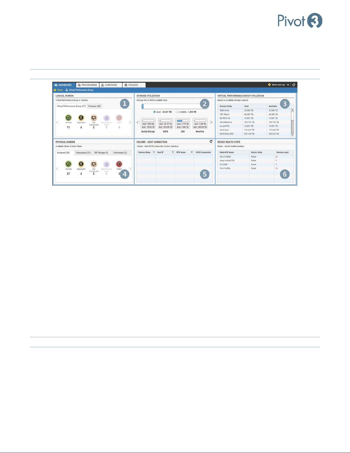
The Home view includes total storage details such as types of drives used (e.g., SATA, SSD) and available capacity,
all Acuity vPG utilization based on available storage, node States, active and inactive iSCSI Host connections, all
logical volumes within the domain, and summary of critical devices within the nodes.
NOTE: Linux-based Dashboards will not populate with nodes & vPGs until Discover Nodes
has been performed.
1. Logical Domain Health Summary
The Logical Domain component shows a summary of the health states for all discovered vPGs in the domain and
Volumes in separate tabs.
2. Storage Utilization
The Storage Utilization component shows a summary of all used and available storage in the domain.
3. Virtual Performance Group Utilization
The Virtual Performance Group Utilization component shows a list of vPGs along with their total and available
capacities. This data can be sorted in ascending or descending order by clicking on the desired column header.
4. Physical Domain Health Summary
The Physical Domain component shows a health summary of all nodes. The node can be in any status among
Normal, Degraded, Not Connected, Maintenance Mode, or Failed. This section breaks down into four
categories: Assigned, Unassigned, N5 Storage, and Unlicensed.
The Unlicensed view will only show up if an unlicensed vSTAC node has been discovered in the domain.
NOTE:
39
|
DOC-246-GDE-Pivot3 Acuity 2.3 Setup & User Guide-v1.0.docx
Page 40

X-Series Hyperconverged Nodes Powered by Acuity
Setup & User Guide, v1.0
5. Volume – Host Connection
This component shows details about the volumes, the hosts and vPGs they belong to, and all iSCSI Connection
statuses to them. A refresh icon ( ) is available at the top right of the component to update the displayed
information whenever necessary. When populated, the columns for Volume Name, Host IP, and vPG Name have a
filter function ( ) for limiting the amount of information displayed. The numbers shown in the iSCSI Connection
column represent the number of connection paths between the ESXi Server iSCSI initiator and the volume, and
whether the connections are active or inactive.
6. Device Health State
This component lists the summary of devices that are failed or rebuilding or otherwise need administrative
attention. This component will only be populated if there are errors on any assigned/unassigned nodes. In the
case of assigned nodes, vPG name will be listed.
| 40
DOC-246-GDE-Pivot3 Acuity 2.3 Setup & User Guide-v1.0.docx
Page 41
X-Series Hyperconverged Nodes Powered by Acuity
Setup & User Guide, v1.0
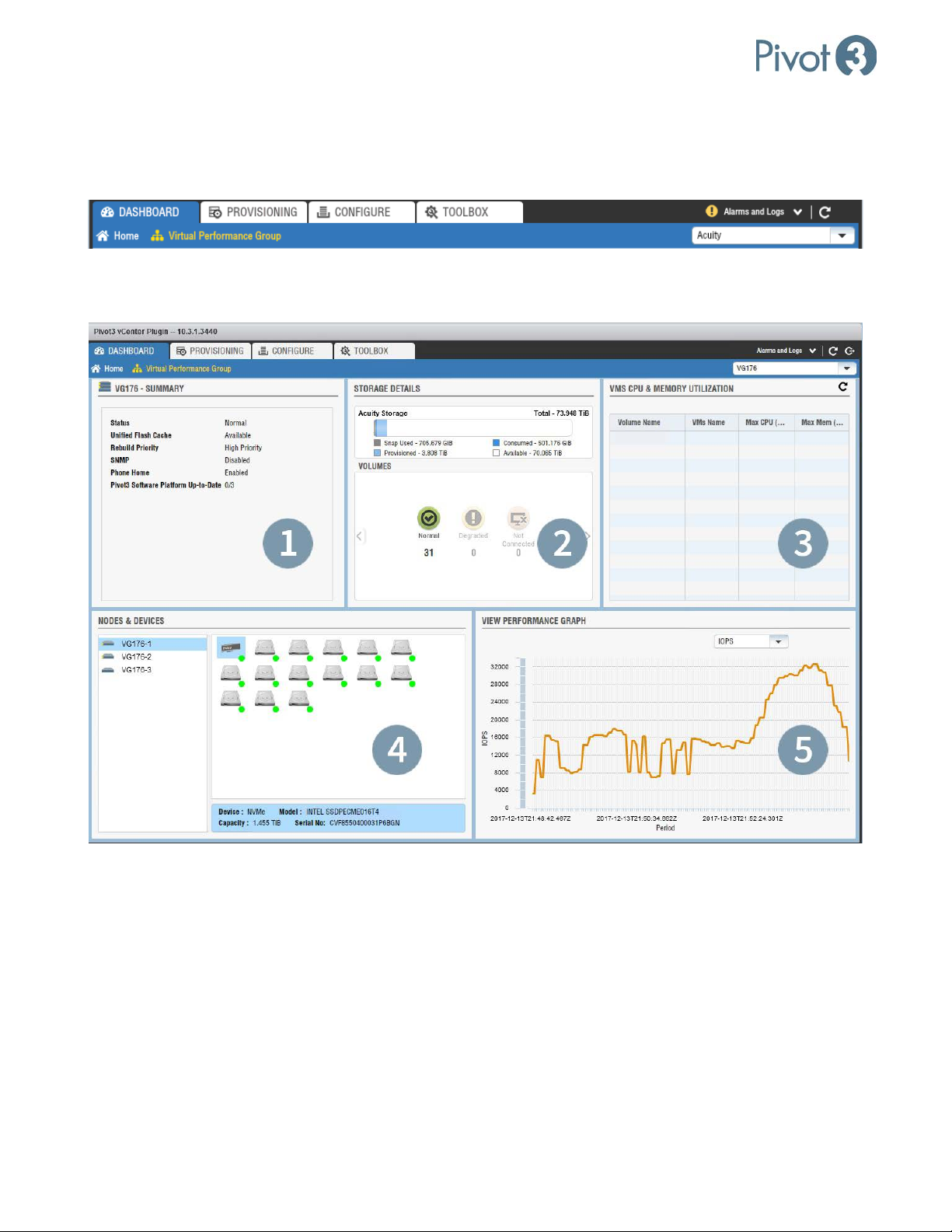
Dashboard Overview – Virtual Performance Group
The Virtual Performance Group Dashboard will not populate until a vPG is populated in the upper right dropdown box. Ensure the desired vPG has been selected.
After the desired vPG has been selected, the components will populate with detailed information about that vPG.
Dashboard Tab
1. vPG - Summary
This component shows the properties summary of the vPG selected.
2. Storage Details
This component shows a summary of the storage in the selected vPG, including used and available capacity. The
Volumes section displays a summary count of the states of the volumes in the vPG.
41
|
DOC-246-GDE-Pivot3 Acuity 2.3 Setup & User Guide-v1.0.docx
Page 42
X-Series Hyperconverged Nodes Powered by Acuity
Setup & User Guide, v1.0
3. VM’s CPU & Memory Utilization
This component shows a list of VMs, the vCenter datastore volume that the VMs reside on, and the maximum CPU
and Memory Utilization they were configured with. Click the refresh icon ( ) at the top right of the component to
populate this data.
4. Nodes & Devices
This component shows a list of nodes in the vPG as well as a detailed summary of the devices inside the selected
node. Selecting a node displays a graphical representation of the devices in the node with details on the device’s
state, tier type, model name, capacity, and location. It will also show the NVMe details once the NVMe icon is
clicked (this is only applicable to accelerated nodes). A colored status dot provides a quick indication of device
status with the following color code:
Normal (Green) Failed (Red) Rebuilding (Blue)
NOTE: The position of the drive in the graphical representation does not represent the physical location of the drive
in the node. Drive placement information is provided at the bottom of the window when the drive is selected
Nodes & Devices component.
in the
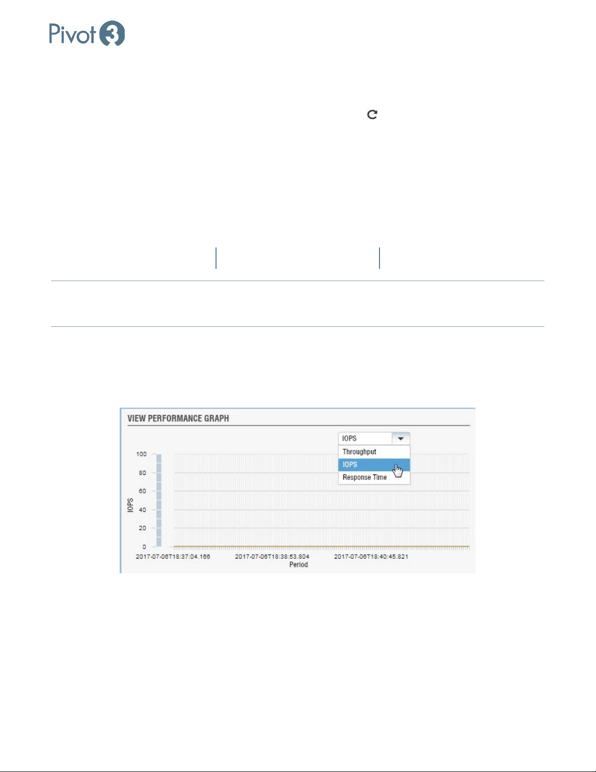
5. View Performance Graph
This component shows a graph of select details for the currently selected vPG. Choose which data to display from
the drop-down box at the top right of the component. Data choices are Throughput, IOPS, or Response Time.
The chart will then populate with a line graph displaying the selected data for the last 10 minutes.
| 42
DOC-246-GDE-Pivot3 Acuity 2.3 Setup & User Guide-v1.0.docx
Page 43
X-Series Hyperconverged Nodes Powered by Acuity
Setup & User Guide, v1.0
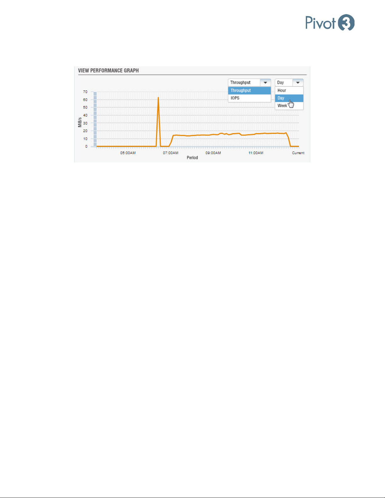
vSTAC vPGs will have different options. For these environments, choose between IOPS and Throughput View.
There is also the opportunity to customize the line graph for the previous Hour, Day, or Week.
Provisioning Overview: Storage Provisioning
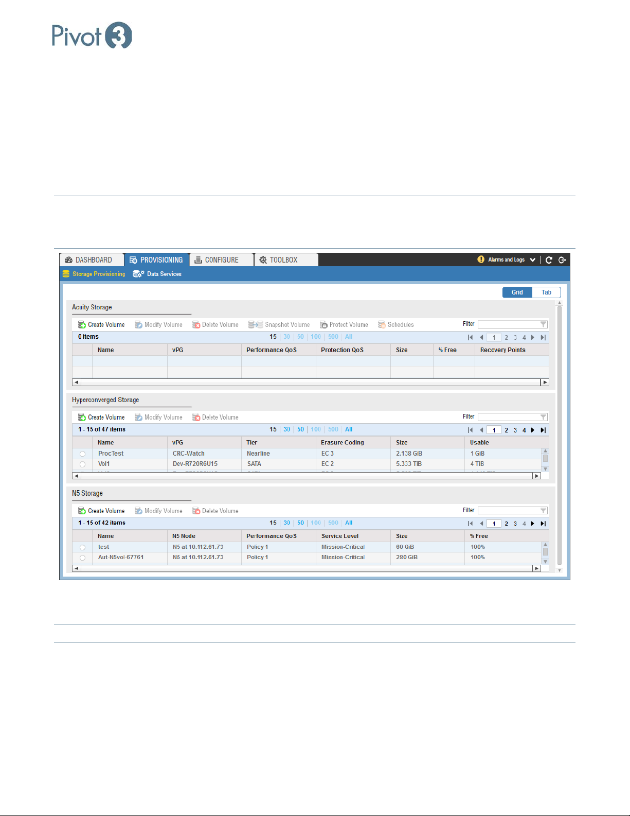
The Provisioning tab provides a view of Acuity Storage, Hyperconverged Storage, and N5 Storage, depending on
environment setup. There are two views on this tab: Storage Provisioning and Data Services.
43
|
DOC-246-GDE-Pivot3 Acuity 2.3 Setup & User Guide-v1.0.docx
Page 44
X-Series Hyperconverged Nodes Powered by Acuity
Setup & User Guide, v1.0
Storage Provisioning
Storage Provisioning provides for the creation of Acuity Storage volumes in the same window as vSTAC and N5
volumes. The volume creation procedures differ in presentation from creating volumes in the Configure tab, but
the result remains the same. There are view options on the right side of this tab when selected: Grid view and Tab
view. Grid view provides an overview of all storage available, whether set up in Acuity or vSTAC environments; Tab
view provides the opportunity to get a more focused view in either environment. N5 Storage, if applicable, is also
visible here.
If only one platform solution has been connected, that will be all that is visible.
NOTE:
NOTE: Acuity vPGs will not be visible in the Hyperconverged Storage tab, and vSTAC vPGs will not be visible in the
Acuity Storage section.
From here, an administrator can also set up schedules to take snapshots and change the performance policies on
individual volumes.
NOTE: For more information on Volumes, Snapshots, and how to protect them, see Section 12
.
| 44
DOC-246-GDE-Pivot3 Acuity 2.3 Setup & User Guide-v1.0.docx
Page 45
X-Series Hyperconverged Nodes Powered by Acuity
Setup & User Guide, v1.0
Data Services
CRITICAL: This view is only available on the Acuity software platform.
From the Data Services view, tabs provide access to the following information about the platform:
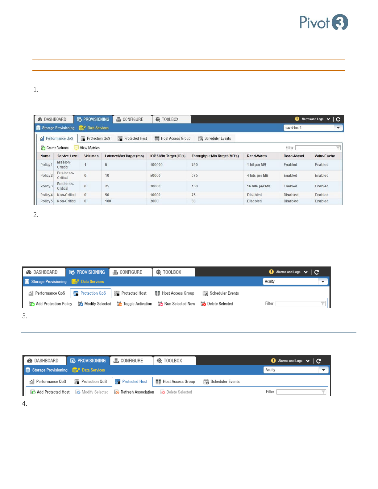
Performance QoS: Volumes are assigned to one of the five performance policies when created. Volumes can
be migrated between policies on the fly even while application servers are actively using the volumes. The
Performance QoS tab provides the ability to Create Volume or View Metrics on each Policy level.
Protection QoS: Volumes may have been assigned a protection policy when created. From this screen,
administrators can perform the following actions:
• Add Protection Policy
• Modify Selected
• Run Selected Now
• Delete Selected
• Toggle Activation
Protected Host: Protected hosts are servers that utilize the application-consistent snapshot capability. From this
menu, users can add, modify, or delete protected hosts or refresh associations with the protected hosts.
If new volumes are added to an existing protected host, Refresh Associations must be used for the new volumes to be
NOTE:
discovered and protected by that host.
Host Access Group: For servers to access volumes, the volumes must be assigned to a host access group that the
servers are also associated with. Host access groups are logical representations of the servers that may have iSCSI
initiators that will connect to the volumes in the group. ESXi hosts need to be assigned to a Host Access Group to
allow the servers to connect to the datastores. By controlling the connection of server to volume, host access groups
promote data integrity and security. For more information on Host Access Groups, consult Section 10.
45
|
DOC-246-GDE-Pivot3 Acuity 2.3 Setup & User Guide-v1.0.docx
Page 46
Setup & User Guide
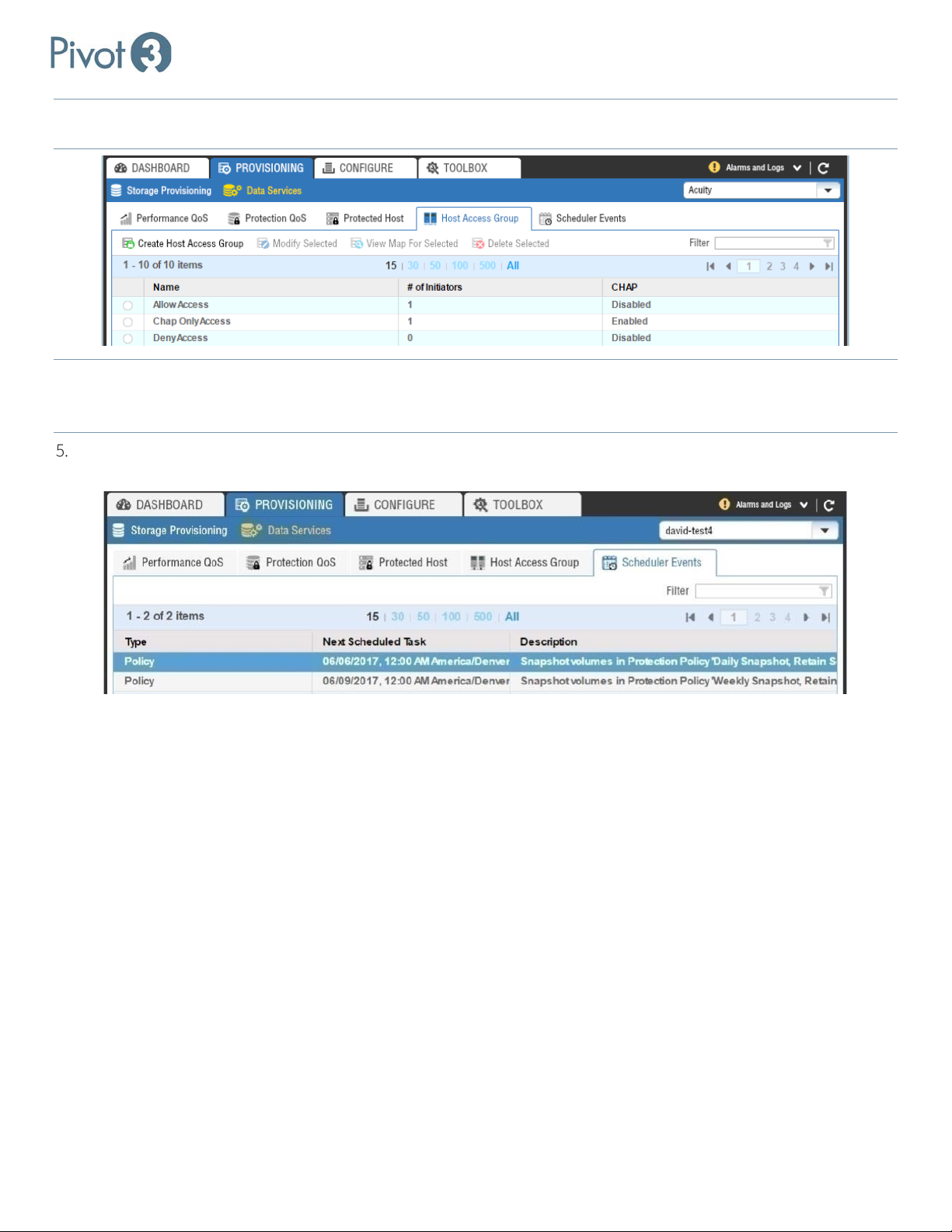
NOTE: Three Host Access Groups are set up by default: Allow Access, Chap Only Access, and Deny Access. Chap Only Access
is limited to volumes or Host Access Groups that have been set up with CHAP Authentication.
NOTE:
CHAP Authentication must be set up at the Volume level for vSTAC vPGs and at the Host Access Group level for Acuity
vPGs. Allow Access Host Access Group will provide access to any user with credentials for this Plugin and is not
recommended.
Scheduler Events: The Scheduler Events tab lists upcoming scheduled tasks. Policies are described more thoroughly
in Protection Policies Explained.
| 46
DOC-246-GDE-Pivot3 Acuity 2.3 Setup & User Guide-v1.0.docx
Page 47
Setup & User Guide
Configure Tab: Overview
The Configure tab allows the user to view the Logical and Physical layouts of the storage and vPGs in the Acuity software
platform. The Logical, Physical, and Unlicensed views are available, and Acuity vPGs as well as N5 arrays and vSTAC
vPGs are supported in this section.
The Unlicensed view will not be a common utility on Acuity configurations.
NOTE:
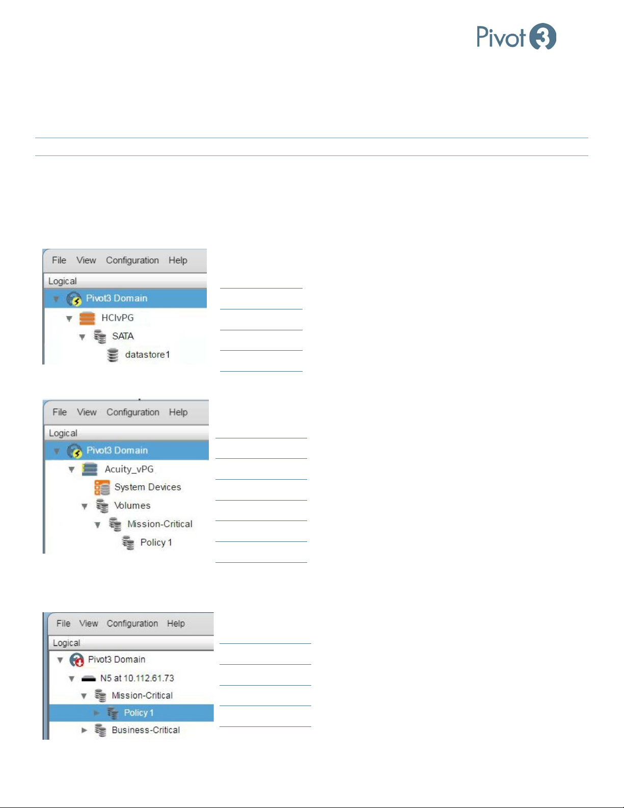
Logical Tree View
The Logical tree view covers vSTAC vPGs as well as Acuity-based vPGs. vSTAC-based vPGs do not contain the same Quality
of Service options as Acuity vPGs do, and therefore are not displayed in the same structure.
Logical Structure – vSTAC vPGs
Domain Level
vPG Level
Logical Structure – Acuity vPGs
Logical Structure – N5 Storage Arrays
Tier Level
Volume Level
Domain Level
vPG Level
Tier Level
Volume Level
Criticality Level
Policy Level
Domain Level
Node Level
Criticality Level
Policy Level
47 |
DOC-246-GDE-Pivot3 Acuity 2.3 Setup & User Guide-v1.0.docx
Page 48
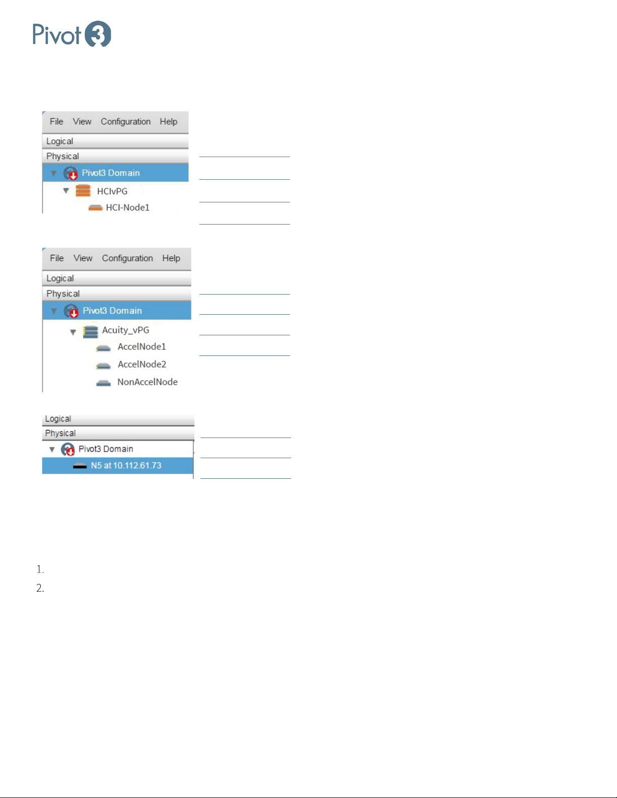
Physical Tree View
Physical Structure: vSTAC vPGs
Physical Structure: Acuity vPGs
Domain Level
vPG Level
Node Level
Domain Level
Setup & User Guide
vPG Level
Node Level
Physical Structure: N5 Storage
Domain Level
Node Level
Smart Clean
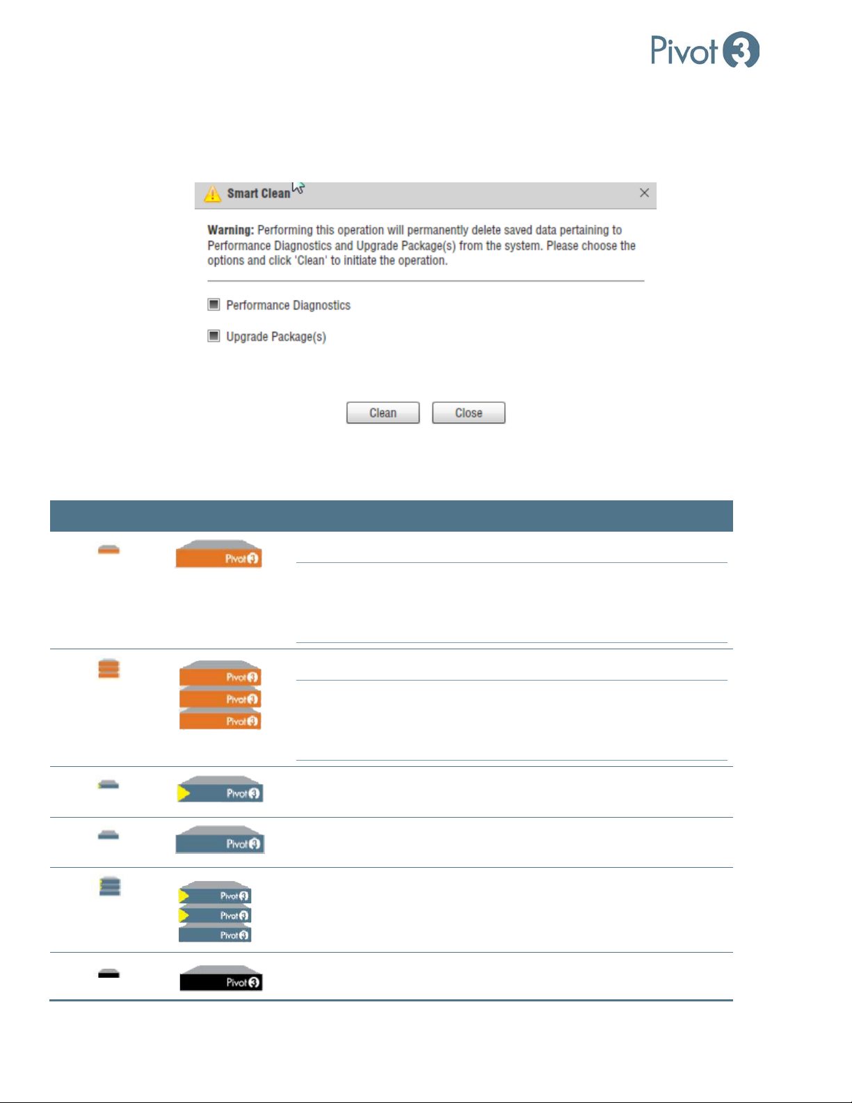
Smart Clean is a new option that cleans up old data that may accumulate during Performance Diagnostics data collection
and log pulls. This feature also provides an option to clean up any outdated OS Packages.
On the Configure tab, navigate to Help > Smart Clean.
Click the boxes next to the desired option(s) and click Clean.
| 48
DOC-246-GDE-Pivot3 Acuity 2.3 Setup & User Guide-v1.0.docx
Page 49
Setup & User Guide
a. Performance Diagnostics removes old data that was generated during previous log pulls and is no longer being
used.
b. Upgrade Package(s) removes outdated Upgrade files and frees up disk space on the Upgrade Package
repository.
Acuity Software Platform: Node Icons Explained
Status flags that show up next to these icons in the Plugin are explained in Appendix A.
Small Icon Large Icon Represents
A Healthy vSTAC node capable of being in a vSTAC vPG
Any node running vSTAC OS version 7.x will have normal
NOTE:
functionality in the Acuity version of the plugin. Only vSTAC
nodes running 2.2 or later will be eligible for Acuity vPG
membership.
A Healthy vSTAC vPG
Any node running vSTAC OS version 7.x will have normal
NOTE:
functionality in the Acuity version of the plugin. Only vSTAC
nodes running 2.2 or later will be eligible for Acuity vPG
membership.
A Healthy X-Series Accelerator (2500 or 6500) node capable of being
one of two accelerator nodes in an Acuity vPG
A Healthy X-Series Standard (2000 or 6000) node capable of being
one of the non-accelerator nodes in an Acuity vPG
A Healthy Acuity vPG with exactly two Accelerator nodes and up to 10
(Hybrid) or 14 (Flash) non-accelerator nodes
A Healthy N5 node capable of being a part of an N5 Storage Array
49 |
DOC-246-GDE-Pivot3 Acuity 2.3 Setup & User Guide-v1.0.docx
Page 50
Setup & User Guide
Toolbox: Overview & Reporting
The Toolbox tab has been provided as a central location for tools that are useful for diagnosing potential issues on
managed vPGs. There are three categories for the Toolbox view: Performance Monitor, Performance Diagnostics, and
Connection Map.
CRITICAL:
The Toolbox tab will not populate until a vPG is chosen in the dropdown box in the top right of the screen.
Performance Monitor
The Performance Monitor view provides a view of the activity within the domain and each volume within an Acuity vPG.
These charts update continuously for the most up-to-date information.
: Only Acuity vPGs will be visible in this section. vSTAC vPGs will be greyed out and not selectable.
NOTE
Begin by choosing a vPG to monitor in the top right drop-down box.
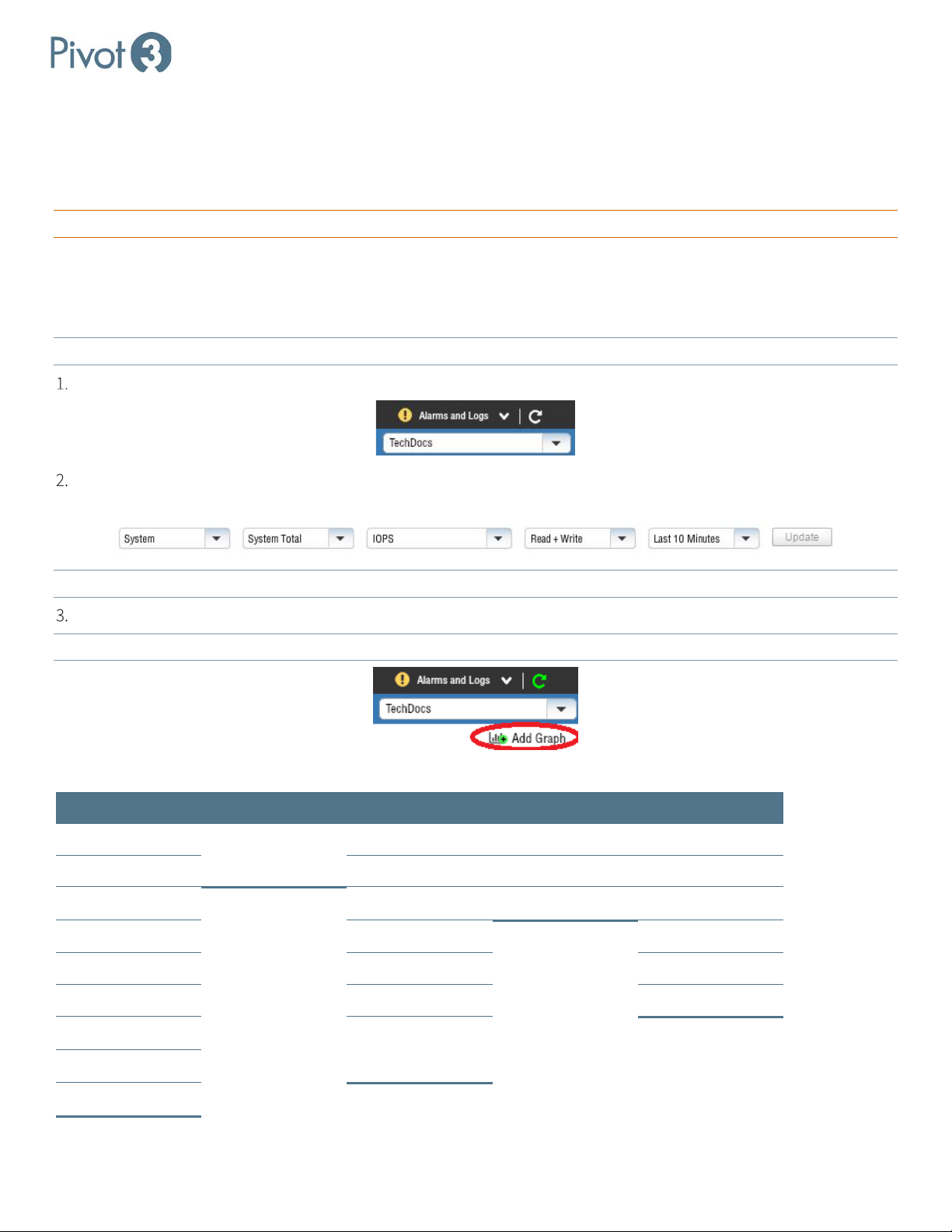
For the selected vPG, make selections from the drop-down boxes at the top of the graph. Up to 12 graphs may be
displayed simultaneously for comparison viewing.
NOTE: To switch the graph from one view to another, make different selections in the drop-down boxes and click Update
To add a new live monitor, click the Add Graph feature under the vPG dropdown box.
Maximum of 12 graphs are available at one time.
NOTE:
.
The options are broken out in the table below:
Type of Monitor Category Metrics I/O Type Interval
System Contingent on
Service Level IOPS Write Last Hour
Monitor Selection
Throughput Read Last 10 Minutes
Policy Queue Depth Read + Write Last Day
Volume Block Size Last Week
Storage Processor Response Time Last Month
Network Port IOPS Histogram Last Year
Access Group Response Time
Host Connection
Histogram
Tier
| 50
DOC-246-GDE-Pivot3 Acuity 2.3 Setup & User Guide-v1.0.docx
Page 51

Setup & User Guide
Performance Diagnostics
NOTE: This section is available for both Acuity and vSTAC vPGs.
Performance Diagnostics provides an in-depth look into the performance of network connections and disk usage for the
selected Acuity vPG. This view provides Network information from a node perspective and is updated when the dropdown
menu is changed. Performance Diagnostics does not update continuously like Performance Monitor, and the view will
remain static until a variable is changed; however, multiple entities can be selected for viewing.
For the selected vPG, there are two main views: Global View and Node View. Global View separates Networks and
Storage (as well as Volumes, as applicable) into relevant sub-categories, and shows this data as pulled from the vPG.
Node View provides information on those same sub-categories specific to the chosen node.
These options all have the same basic drop-down menu at the top that allow for the selection of Time, Entities, Metrics,
Chart Type, and Scale Type.
• Time selections are contingent on vPG type and offer: 5 minutes, 1 hour, 1 day, 1 week, or 1 month.
• Entities dropdown provides different options depending on the view chosen in the navigation tree. Global View
Entities will be a list of the available nodes on which to pull this data, and Node View Entities are the same Networks
listed above in Global View. Choose one, multiple, or Select All.
• Metrics options will vary depending on the option chosen in the navigation tree. The same data sets are available two
different ways: from the Global View or Node View.
View Level Tier Category Available Metrics
Global View Networks Dednet
SAN0
SAN1
Node View Networks
Receive bytes
Receive packets
Transmit bytes
Transmit packets
Receive multicast
Global View Storage Cache
SATA
Maximum Latency (ms)
Write IOPS
Write MBPS
Total IOPS
Total MBPS
Queue Write Avg Queue Depth
Queue Write Max Queue Depth
Queue Write Percent Busy
Queue Write Avg Latency (ms)
Queue Total Avg Queue Depth
Queue Total Max Queue Depth
51 |
DOC-246-GDE-Pivot3 Acuity 2.3 Setup & User Guide-v1.0.docx
Page 52

View Level Tier Category Available Metrics
Setup & User Guide
Node View Storage
Queue Total Percent Busy
Queue Total Avg Latency
Device Write Avg Queue Depth
Device Write Max Queue Depth
Device Write Percent Busy
Device Write Avg Latency (ms)
Device Total Avg Queue Depth
Device Total Max Queue Depth
Device Total Percent Busy
Device Total Avg Latency (ms)
Read IOPS
Read MBPS
Queue Read Avg Queue Depth
Queue Read Max Queue Depth
Queue Read Percent Busy
Queue Read Avg Latency (ms)
Device Read Avg Queue Depth
Device Read Max Queue Depth
Device Read Percent Busy
Device Read Avg Latency (ms)
• Line Chart or Bar Chart: Choose view between these. Line Chart is chosen as default.
• Linear Scale or a Log Scale.: Choose view between these. Linear Scale is chosen as default.
| 52
DOC-246-GDE-Pivot3 Acuity 2.3 Setup & User Guide-v1.0.docx
Page 53
Setup & User Guide
Connection Map
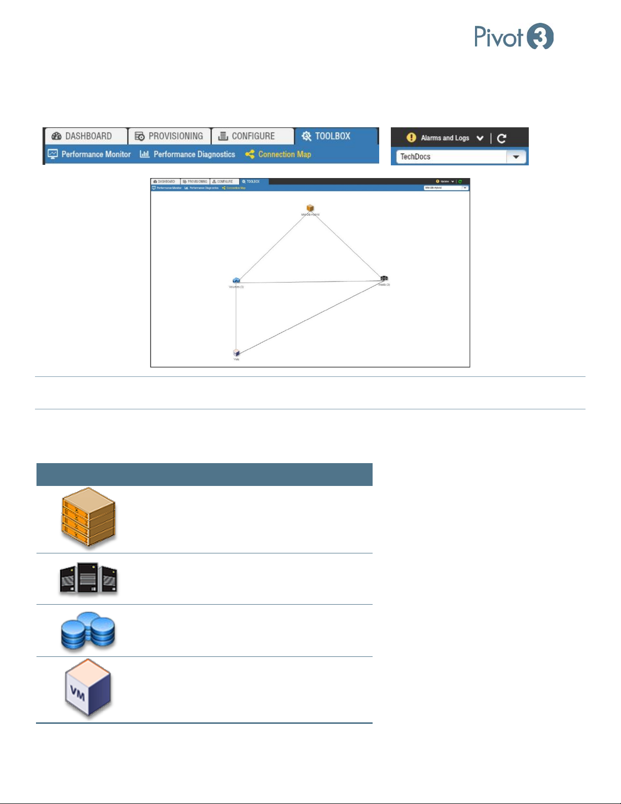
The Connection Map provides an interactive, high-level mapping diagram of the local environment. Click on the
Connection Map view of the Toolbox tab, then choose the desired vPG from the drop-down box in the top right corner.
NOTE:
The entities shown here may be moved around to improve visibility or double-clicked to drill down further into the
domain structure. Hover over each icon for more information.
After selecting a vPG, the screen will display a summary diagram that allows the user to drill down for additional details on
several aspects of the vPG. At this highest level, the map has icons that represent the nodes in the vPG, the volumes in the
vPG, the ESXi hosts associated with the vPG, and the VMs hosted by these ESXi hosts.
Icon Double-Click for Details On
vPG
Host
Volume
VMs
53 |
DOC-246-GDE-Pivot3 Acuity 2.3 Setup & User Guide-v1.0.docx
Page 54
Setup & User Guide
Connection Map – Node Map View
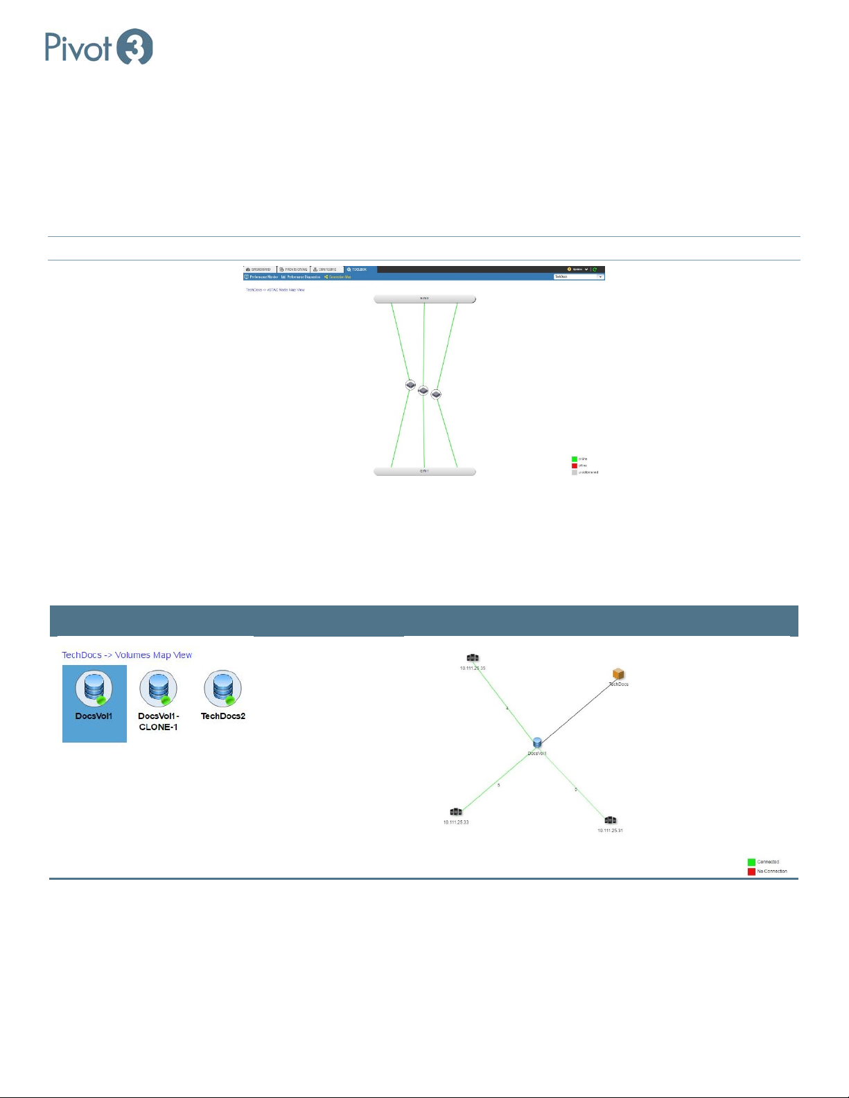
Double-clicking on the vPG icon will provide the Node Map View with color-coded connectivity displayed. This view
shows the nodes that make up the selected vPG.
Hovering over one of the node icons will provide a popup with additional details about the node (e.g., node name, model,
current physical state); hovering over the colored line will display data round trip times. Lines will not be colored for vPGs
running a vSTAC OS version lower than 7.3.0.
NOTE: Double-clicking on any of the nodes displayed will navigate to the Configure
tab view for that node.
To return to the vPG view, click on the leftmost entity in the top left of the window.
Connection Map – Volume Details
Double-clicking on the Volumes icon will navigate to a Volumes Map View. In this view, each volume may be doubleclicked to navigate to the Volume Details Map view for that specific volume.
Volumes Available Volume Details Map View
The combination of the icons here represents, for the selected volume:
• Hosts connected to the volume
• Number of connections from each host to the volume
To return to the vPG view, click on the leftmost entity in the top left of the window.
| 54
DOC-246-GDE-Pivot3 Acuity 2.3 Setup & User Guide-v1.0.docx
Page 55
Setup & User Guide
Connection Map – Host Details
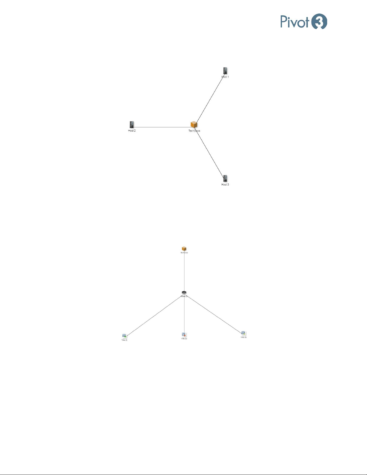
Double-clicking on any of the Hosts icon in the Connection Map will navigate to the Hosts Map View.
Hover over any Host icon to see more granular information about that specific host.
To return to the main vPG view, click on the leftmost entity in the top left of the window or double-click on the vPG icon.
Connection Map – VM Details
Double-clicking the VMs icon will navigate to the VM Map View.
This view shows VMs and hosts associated with the selected vPG as well as the connection details of the host and VMs
(powered on shows a green arrow icon, and powered off shows a red square icon).
To return to the main vPG view, either double-click on the vPG icon in this screen or click the click on the leftmost entity in
the top left of the window.
To return to the Hosts Map View, double-click on the Hosts icon.
55 |
DOC-246-GDE-Pivot3 Acuity 2.3 Setup & User Guide-v1.0.docx
Page 56
Setup & User Guide
vCenter Alarms & Notifications
The Alarms section of the plugin notifies the administrator of active issues requiring attention. The audible alarm has
been disabled in the plugin’s functionality, but the plugin provides additional tabs for more detail.
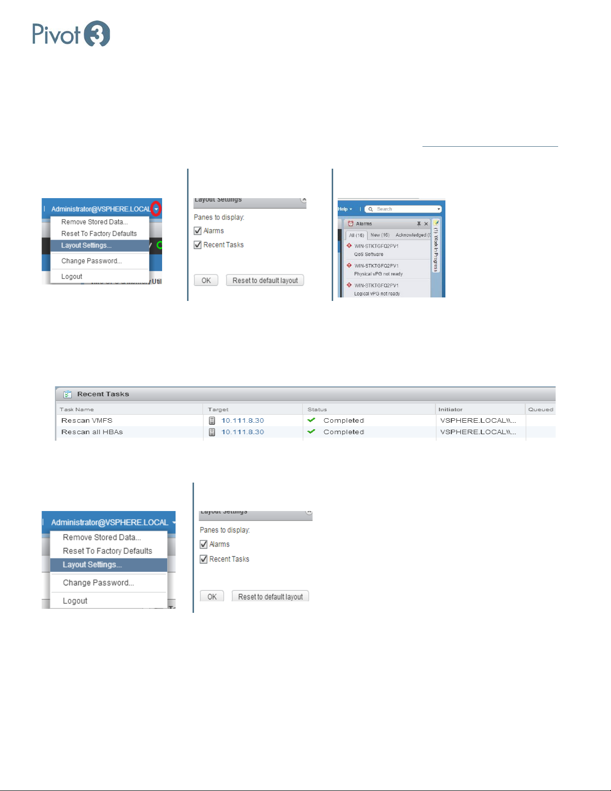
If the Alarms panel is not visible, enable it by navigating to Layout Settings from the drop-down arrow next to the domain
username at the top of the browser window and outside of the plugin (for this example, [email protected]
used). Then check the box next to Alarms, click OK, and a vCenter Alarms panel will appear next to the plugin.
Username > Layout Settings Check Box Next To “Alarms” vCenter Alarms Panel
is
Tasks
The vSphere Web Client has two task windows to monitor: Tasks and Recent Tasks.
Recent Tasks is an optional window at the bottom of the vSphere Web Client that reports every task performed on the
vCenter host by anyone with access.
If this window disappears, it can be reactivated by clicking the credentials at the top of the plugin and choosing Layout
Settings. A dialog box will pop up with two checkboxes; select Recent Tasks and click OK.
Username > Layout Settings Check Box Next To “Recent Tasks”
There are two ways to access the Task Console. Click the Tasks menu item on the left pane of the vSphere Web Client as
shown, or click More Tasks at the bottom right corner of the Recent Tasks Window when visible.
These tasks are different from the tasks accessible through the Pivot3 Plugin via the Alarms and Logs menu.
| 56
DOC-246-GDE-Pivot3 Acuity 2.3 Setup & User Guide-v1.0.docx
Page 57

Setup & User Guide
Tasks Menu Item in Left Pane
Task Console Window
“More Tasks” Hyperlink on Recent
Tasks Window
NOTE: To return to the Main Screen views of the vCenter Plugin, click Home
at the top of the left menu pane.
Web Plugin Alarms and Logs
The Alarms and Logs menu provides a quick shortcut to Alarms that are active, a list of the most recent tasks performed
by the Plugin, OS version running on each node in the vPG, and a list of upcoming scheduled tasks.
The Alarms/Tasks listed here are Plugin-specific and differ from the Alarms/Recent Tasks window generated by the
NOTE:
vSphere Web Client.
57 |
DOC-246-GDE-Pivot3 Acuity 2.3 Setup & User Guide-v1.0.docx
Page 58
Setup & User Guide
Changing VMware vCenter Credentials
If the user credentials used for the VMware login needs to be changed for any reason, the credentials in the vCenter Plugin
must be changed first to retain functionality once the VMware credentials are altered.
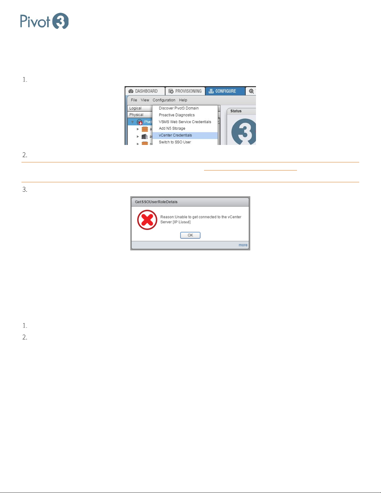
From the Domain level on the Configure tab, select Configuration > vCenter Credentials.
Enter the new username and password expected to be used for the VMware Administrator login.
CRITICAL: The credentials in the vCenter Plugin must be changed before the credentials in vCenter are altered, or access
to the plugin will not be possible.
If this order is not adhered to during credential changes, an error message will appear:
Plugin Troubleshooting
Flash Storage Limitation
When the plugin uses its available storage space, it will provide a popup that prompts the user to increase storage space
or block the write operation. If this popup is not attended to, it can consume all available memory and cause the browser
to terminate the plugin. This can be avoided a couple ways:
Refresh the browser page occasionally (approximately once an hour) to free up the browser memory
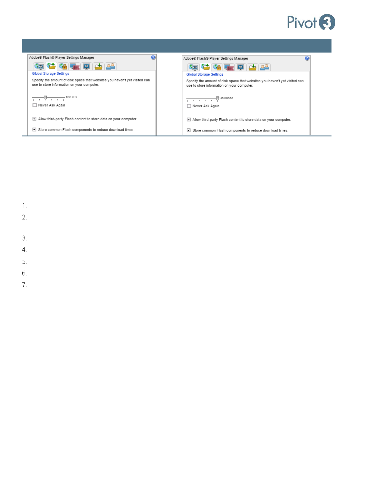
Alter the browser’s Global Storage Settings to Unlimited or check the box labeled Never Ask Again.
| 58
DOC-246-GDE-Pivot3 Acuity 2.3 Setup & User Guide-v1.0.docx
Page 59
Setup & User Guide
Default Settings Suggested Settings
NOTE: If error message [1] Error creating firewall rule incorrect function displays, that means that the Windows Firewall
Service has been stopped but not disabled. Either restart or disable the firewall service.
Mutual CHAP
To ensure a Mutual CHAP handshake between volumes and a Host Access Group, a manual procedure must be followed.
This issue should be resolved in future releases of the Pivot3 Acuity software platform.
Use the Pivot3 vCenter Plugin to Create a Host Access Group with Mutual CHAP configured.
Use the Pivot3 vCenter Plugin to create a Volume and assign the Host Access Group with Mutual CHAP configured to
the volume. More information on this procedure is found in
Section 11.
Rescan for new storage devices on all ESXi hosts.
Disable CHAP on all ESXi hosts.
Re-enable CHAP on all ESXi hosts.
Rescan for new storage devices on all ESXi hosts.
The ESXi hosts will now see the new volume with Mutual CHAP properly configured, and can be formatted as a
datastore.
59 |
DOC-246-GDE-Pivot3 Acuity 2.3 Setup & User Guide-v1.0.docx
Page 60

Setup & User Guide
Section 8 Configure NIC Ports for Pivot3 Features
The SAN Networks managed through the Acuity software platform operate as an isolated network, processing storage
data through physical switches. Isolating the SAN Networks provides greater security by leaving the Management and
Application networks available to run virtual machines and support an application-specific configured environment.
CRITICAL: If IPv6 has not yet been enabled on the network, follow the procedure in Configuring Pivot3 for IPv4
beginning this section’s procedure.
before
This section describes how to:
• Configure the Management NIC settings in the Pivot3 vCenter Plugin for direct control over the Management Network.
Required items for this section:
• Pivot3 X-Series Node with Acuity software installed that has been powered on and is visible by the Pivot3 vCenter
Plugin.
• Access to desired static IP Address, Subnet Mask, and Default Gateway settings
• Each node will need 1× static MGMT IP and 2× Static Storage IPs.
CRITICAL: Pivot3 features will not function correctly without a Management NIC defined
.
Configure Management NIC in Pivot3 vCenter Plugin
The vCenter Server / Client for the Plugin must be on the same network as the vPG.
In Physical view, select a node (either within a vPG or Unassigned) and click Configuration > Management NIC.
For DHCP, choose the radio button next to Obtain DHCP IP Address and click Apply.
For Static IP, choose the Specify Static IP Address radio button.
Enter Subnet Mask, IP Address, and Default Gateway. Click Apply.
It may be necessary to rediscover the Pivot3 domain to gain access to the Plugin.
CRITICAL: If the IP address that the Plugin connects to is changed on an unassigned node, the node may not be accessible.
This applies to changing any IP address in a vPG.
CRITICAL: Do not configure the Gateway on the SAN NICs.
| 60
DOC-246-GDE-Pivot3 Acuity 2.3 Setup & User Guide-v1.0.docx
Page 61
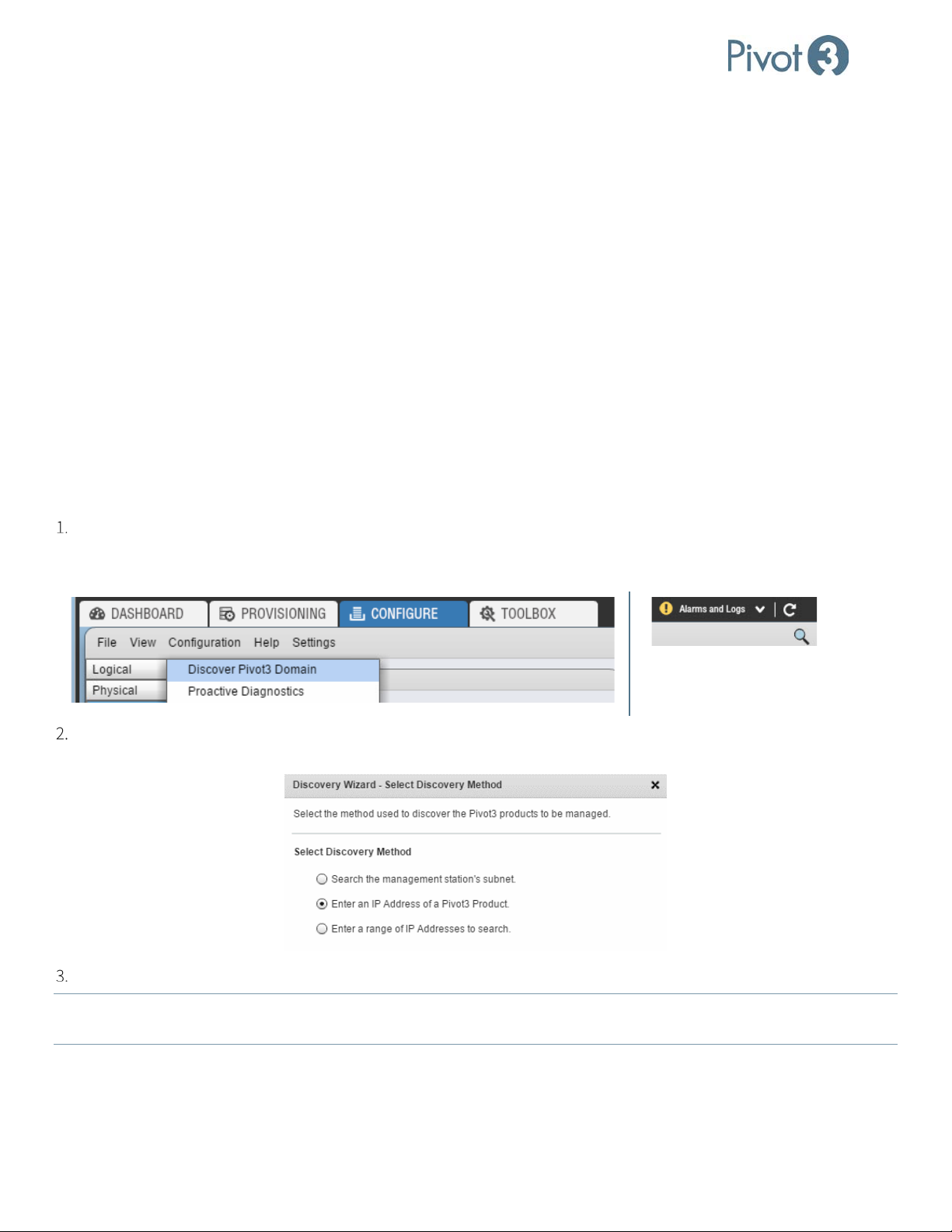
Setup & User Guide
Section 9 Create a Pivot3 vPG
Creating a Pivot3 vPG involves assigning Pivot3 Nodes to a new Pivot3 vPG, naming the vPG, and setting up IP addresses
for the nodes in the vPG.
In this section:
• Discover Pivot3 Nodes in the Acuity Domain
• Create a vPG
Required items for this section:
• The user name and password for the vPG Administrator
• The name to be assigned to the Acuity vPG
• The IP addressing information (IP addresses, subnet masks, and any applicable default gateways) for the SAN
Networks
Discover Nodes
To discover vSTAC, N5, and Acuity X-Series nodes available to the Pivot3 vCenter Plugin, select the Configure tab and
click Configuration > Discover Pivot3 Domain. Alternatively, this can be done by clicking on the magnifying glass at
the upper right corner of the Configure tab underneath the Alarms and Logs dropdown.
Click the radio button next to the desired Discovery Method (Enter an IP Address of a Pivot3 Product
recommended) and click Next. Follow the wizard as prompted until the desired IP addresses are chosen.
If the information entered is accurate, the node will now be visible in the Physical view of the Configure tab.
If the vSMS Web Service is installed directly on the vCenter Server Appliance, perform a targeted IP discovery or IP
NOTE:
range discovery each time the vCSA is restarted.
61 |
DOC-246-GDE-Pivot3 Acuity 2.3 Setup & User Guide-v1.0.docx
Page 62
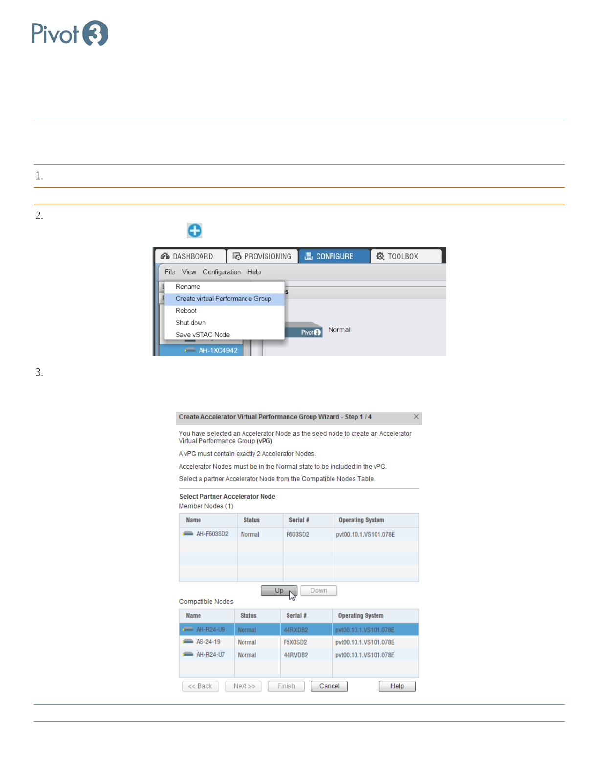
Setup & User Guide
Create an Acuity vPG
Pivot3 X-Series nodes are combined into a vPG, allowing them to be viewed and managed as a single, unified storage
system. A node can only be a member of one vPG, and Acuity vPGs must begin with an unassigned Accelerator node.
Acuity vPGs must have two accelerated nodes and at least one non-accelerated node minimum. A hybrid vPG can
NOTE:
have a maximum of 12 X5 nodes (including two Accelerator nodes) and a flash Acuity vPG can have a maximum of 16
X5 nodes (including two Accelerator nodes).
While still in the Physical tree view at the node level, click on any desired unassigned accelerator node.
CRITICAL: Acuity vPGs must be created by starting with an unassigned accelerator node
.
Click File > Create virtual Performance Group from the main menu. (Alternatively, this can be done by selecting an
available node and clicking on on the upper right of the dialog.)
Choose a partner node. This node must also be an unassigned accelerator node. No other type of node will be visible
during this step. To include an unassigned accelerator node, ensure it is highlighted in the
Compatible Nodes list and
click up. Then click Next.
No more than 2 accelerated nodes may be added to the vPG.
NOTE:
| 62
DOC-246-GDE-Pivot3 Acuity 2.3 Setup & User Guide-v1.0.docx
Page 63
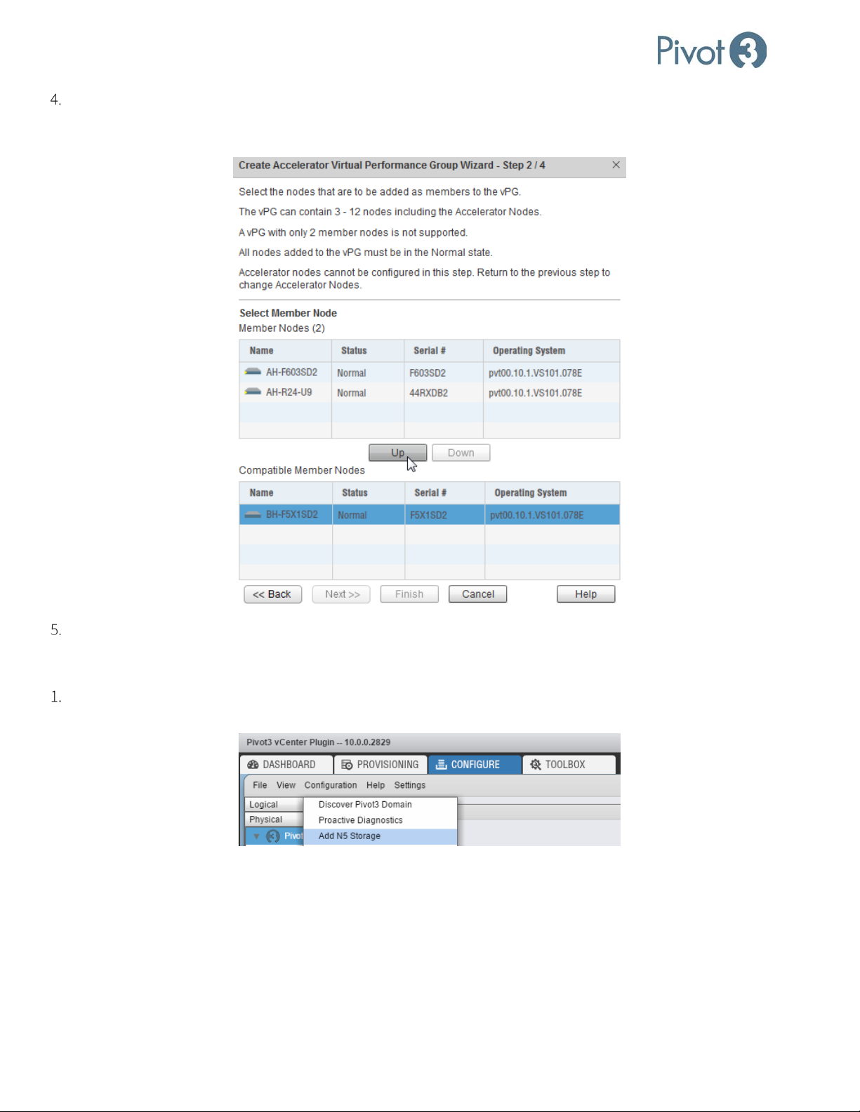
Setup & User Guide
Next, choose an unaccelerated node to add to the vPG. Compatible, unaccelerated X-Series nodes that have been
discovered in the Domain will be visible. Choose the node to add to the vPG and click
Up. When all desired nodes
have been added, click Next.
Name the vPG. The vPG name must be between 1-15 alphanumeric characters.
Add an N5 Storage Node
Adding an N5 Storage Node is similar to configuring vSTAC and X-series nodes. From the Configure tab, click to
highlight the Pivot3 domain level and navigate to Configuration > Add N5 Storage.
63 |
DOC-246-GDE-Pivot3 Acuity 2.3 Setup & User Guide-v1.0.docx
Page 64
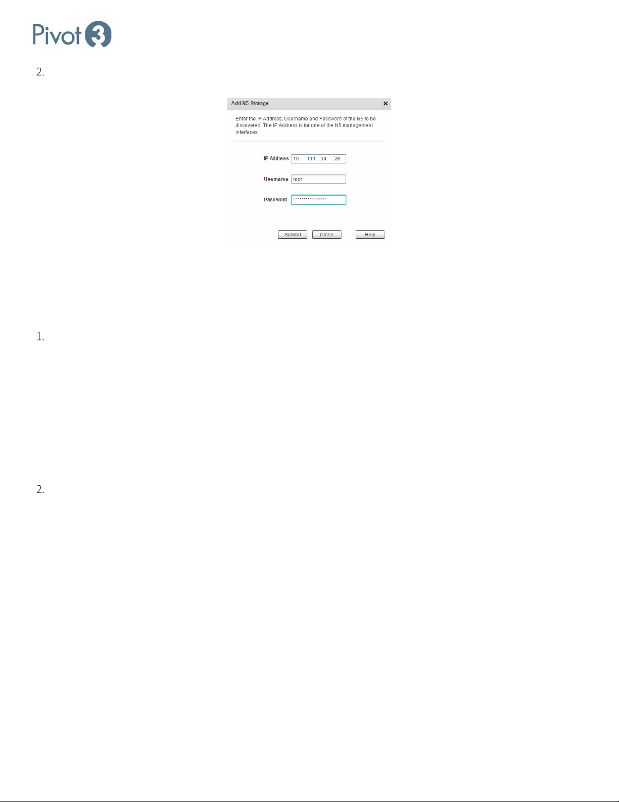
Setup & User Guide
Enter the IP Address, Username, and Password for the desired node and click Submit. If the information entered is
accurate, the N5 Node will now be visible in the Physical view of the Configure tab.
Assign IP Addresses for iSCSI Connectivity
At this point, static IP addresses must be assigned to the nodes so that the iSCSI initiator can connect to Pivot3 logical
volumes and send I/O. Each storage NIC on every member node must be assigned a unique static IP address. If the static
IP addresses have been preconfigured, this step is used to validate the IP addresses of all nodes in the expected subnets.
This requires each IP address to be manually assigned to each NIC in every node (preferred). Values must be entered
in the subnet information table for each SAN Network. The Pivot3 Acuity Plugin will automatically fill in the following
values if any node has a static or DHCP address:
• Subnet Mask –by default is assigned the common Class C value of 255.255.255.0 for each subnet. This value
may be changed based on the IP address requirements of the local SAN Networks.
• Network Address – enter a unique value for each subnet. This is the value of the Network Portion of a full IP
address after applying the Subnet Mask value.
• Default Gateway – set only if a SAN Network is routable to another IP subnet. In most configurations, this field
will be left blank.
For IP address manual entry, click to activate the field, then enter the desired (and verified available) IP addresses into
each NIC for every node until all IP addresses have been entered. Ensure that the IP addresses are valid and available
on the network.
| 64
DOC-246-GDE-Pivot3 Acuity 2.3 Setup & User Guide-v1.0.docx
Page 65
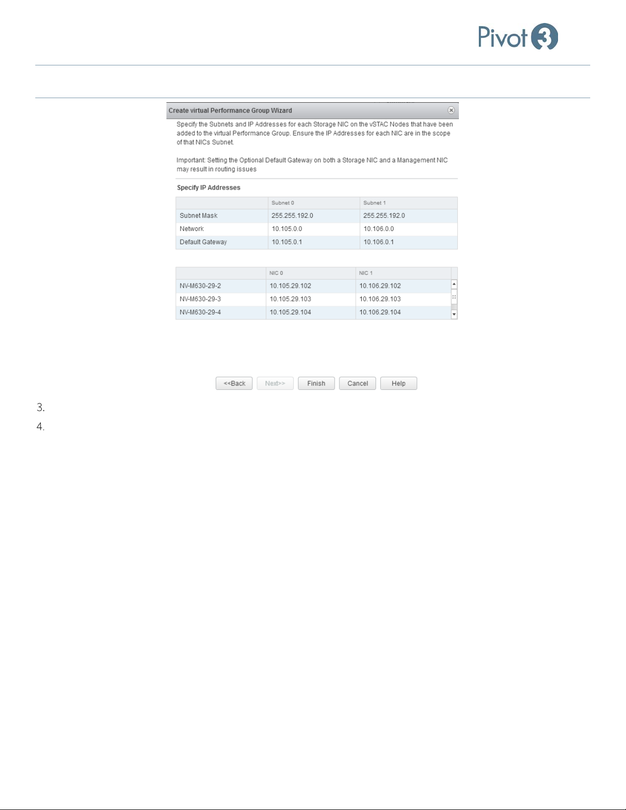
Setup & User Guide
NOTE: The IP Addresses for NIC 0 must all be on the subnet defined by Subnet 0; the IP Addresses for NIC 1 must all be on the
subnet defined by Subnet 1.
Once all IP addresses have been entered or discovered, click Finish.
Verify Administrator credentials (user name and password) if applicable. The vPG creation process will begin. This
may take several minutes to complete; the time to completion varies depending on the number of nodes.
65 |
DOC-246-GDE-Pivot3 Acuity 2.3 Setup & User Guide-v1.0.docx
Page 66

Setup & User Guide
Section 10 Host Access Groups
Host Access Group Basics
For application servers to access volumes, the volumes must be assigned to a host access group that the servers are also
associated with. Host access groups are logical representations of the servers that have iSCSI initiators that will connect to
the volumes in the group. By controlling the connection of server to volume, host access groups promote data integrity
and security.
Default Host Access Groups
There are three default host access groups to which servers and volumes may be assigned:
Default Groups Purpose
Chap Only Access Group for aggregating hosts that use CHAP.
Allow Access Group that allows all hosts to write to any associated volume.
Deny Access
Acuity volumes must be assigned a Host Access Group upon creation. When vSTAC volumes are created, they are put into
the Deny Access group by default. This prevents any unintended I/O from getting to the volume until a valid access group
is set up.
BEST PRACTICE:
Set up and use a custom Host Access Group instead of using any of the default groups.
Group that prevents write access to associated volumes. New volumes are
placed in this group by default.
Servers
A host access group can represent a single iSCSI initiator or multiple iSCSI initiators. Host access groups act as a filter to
restrict access to a volume to a given set of servers.
CRITICAL:
IQNs are used to attach iSCSI initiators to the node. Host access groups limit access to volumes to the iSCSI initiators that
are specifically included in a group. Each iSCSI initiator should have a unique IQN on the IP SAN network.
NOTE: A storage volume cannot be deleted until its associated Host Access Group is changed to Deny Access
When assigning multiple application servers for read/write access to the same volumes, the servers must be aware
via application/hypervisor clustering and/or a clustered file system that they are concurrently accessing the same
volumes. Assigning the same volumes for concurrent read/write access to multiple application servers that are not
cluster-aware will result in data inconsistencies or data-integrity issues on the volume.
.
The most common use cases for host access groups are as follows:
Host Access Group Use Case Description
Single application server host
access group
| 66
One or more iSCSI initiators in a single application server are
assigned to the host access group.
Each iSCSI initiator is identified by an IQN (iSCSI qualified name)
that is unique within the IP SAN.
DOC-246-GDE-Pivot3 Acuity 2.3 Setup & User Guide-v1.0.docx
Page 67

Setup & User Guide
Host Access Group Use Case Description
Cluster of application servers
host access group
Multiple iSCSI initiators in multiple application servers are assigned
to the host access group. Typically, multiple-server host access
groups are used for application/hypervisor server clusters that must
have shared access to volumes.
Each iSCSI initiator is identified by an IQN that is unique within the
IP SAN.
NOTE: Changes to the host access group (e.g., changing IQNs, names, enabling, or changing CHAP) requires user to
disconnect and re-establish iSCSI sessions on the application server. Changes on the application server require the
changes to be mimicked on the plugin as well.
Volumes
A volume can only be assigned to a single host access group at a time.
Assigning volumes to the Allow Access
that connect to the Acuity vPG. Assigning the same volumes for concurrent read/write access to multiple servers that are
not cluster aware will likely result in data inconsistencies or data integrity issues on the volume.
Although a volume’s host access group can be changed, if the new host access group does not include the application
server IQNs that are already connected to the volumes, the volumes will be forcibly disconnected from those
servers/initiators. Similarly, re-assigning volumes to the Deny Access group will forcibly disconnect the volume from
application server(s) connected to the volume.
group is the equivalent to the volume being accessible to all application servers
When creating a volume + datastore with the Pivot3 vCenter Plugin, Mutual CHAP between the Host Access Group and
NOTE:
the volume will not succeed. For more information on this issue, consult Plugin Troubleshooting.
Create a Host Access Group
Log in to vSphere Web Client and locate the IQN of the node to connect the volume’s datastore to.
a. Click on the node level and navigate to Manage > Storage > Storage Adapters. Choose the iSCSI Software
Adapter. The IQN is located on the Properties tab of this screen.
In the Plugin, Provisioning tab > Data Services view > Host Access Group tab > Create Host Access Group.
Enter the IQNs in the Initiator List fields, then click the + to add another node to the Host Access Group.
67 |
DOC-246-GDE-Pivot3 Acuity 2.3 Setup & User Guide-v1.0.docx
Page 68
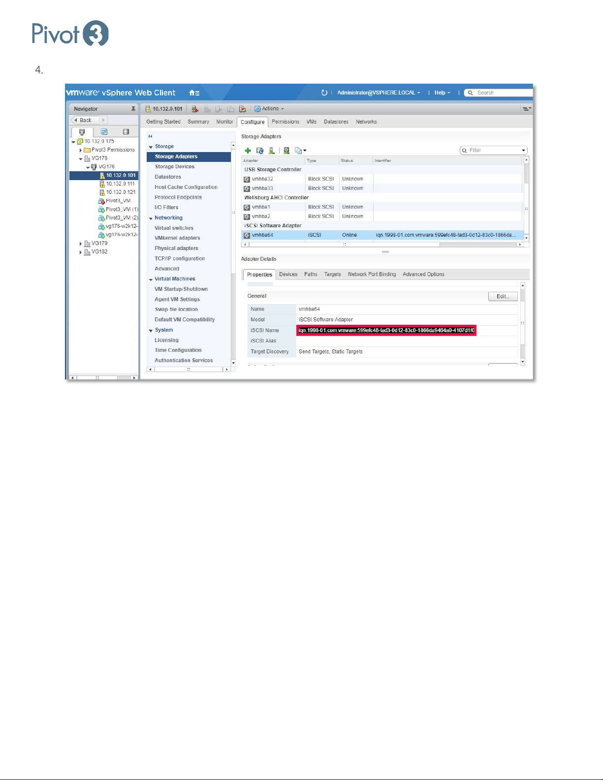
IQNs can be found in vCenter, here:
Setup & User Guide
| 68
DOC-246-GDE-Pivot3 Acuity 2.3 Setup & User Guide-v1.0.docx
Page 69

Setup & User Guide
Section 11 Create Volumes & Associated Datastores
This section explains how to use the Pivot3 vCenter Plugin to create Acuity, vSTAC, and N5 logical volumes and add them
as VMware Datastores. It describes the available Erasure Coding protection levels and setting rebuild priority, capacity,
and iSCSI Initiator access to the volume.
BEST PRACTICE: Provide a custom Access Group instead of the default. Allow Access is strongly discouraged
The administrator can allocate available capacity into logical volumes on the Provisioning tab of the Pivot3 vCenter
Plugin. A logical volume is physically distributed across all devices of the selected storage type on all physical nodes in an
vPG. This approach utilizes the I/O potential from every node and allows the I/O potential for logical volumes containing
frequently accessed data to be increased by adding additional nodes to the host vPG. At the time of volume creation, the
Administrator can name the logical volume, define its capacity, set its protection level (Erasure Coding, vSTAC only) or
Performance Policy (Acuity and N5), and select Protection Policy options (Acuity only).
NOTE:
To create Volumes and Datastores simultaneously, all nodes to be used will need to be already set up and managed
through vCenter.
.
This section describes how to:
• Create a logical volume and associated datastore using the Pivot3 vCenter Plugin
• Configure access to the datastore by multiple ESXi hosts
Required items for this section:
• Volume name to be assigned
• Erasure Coding level of protection desired (vSTAC volumes only)
• Usable capacity in gibibytes (GiB) which is defined as 2
30
= 1073741824 bytes
• Host identifier value to be used to grant access (must be identical to iSCSI Alias – vSTAC volumes only)
• CHAP secret requirements (if applicable)
• Determine which kind of volume to create. In vCenter Plugin 10.x, three types of volumes are available, depending on
the version and Pivot3 software installed on each node:
— Acuity volumes
— vSTAC volumes
— N5 volumes
NOTE: A storage volume cannot be deleted until its associated Host Access Group is changed to Deny Access
69 |
DOC-246-GDE-Pivot3 Acuity 2.3 Setup & User Guide-v1.0.docx
.
Page 70
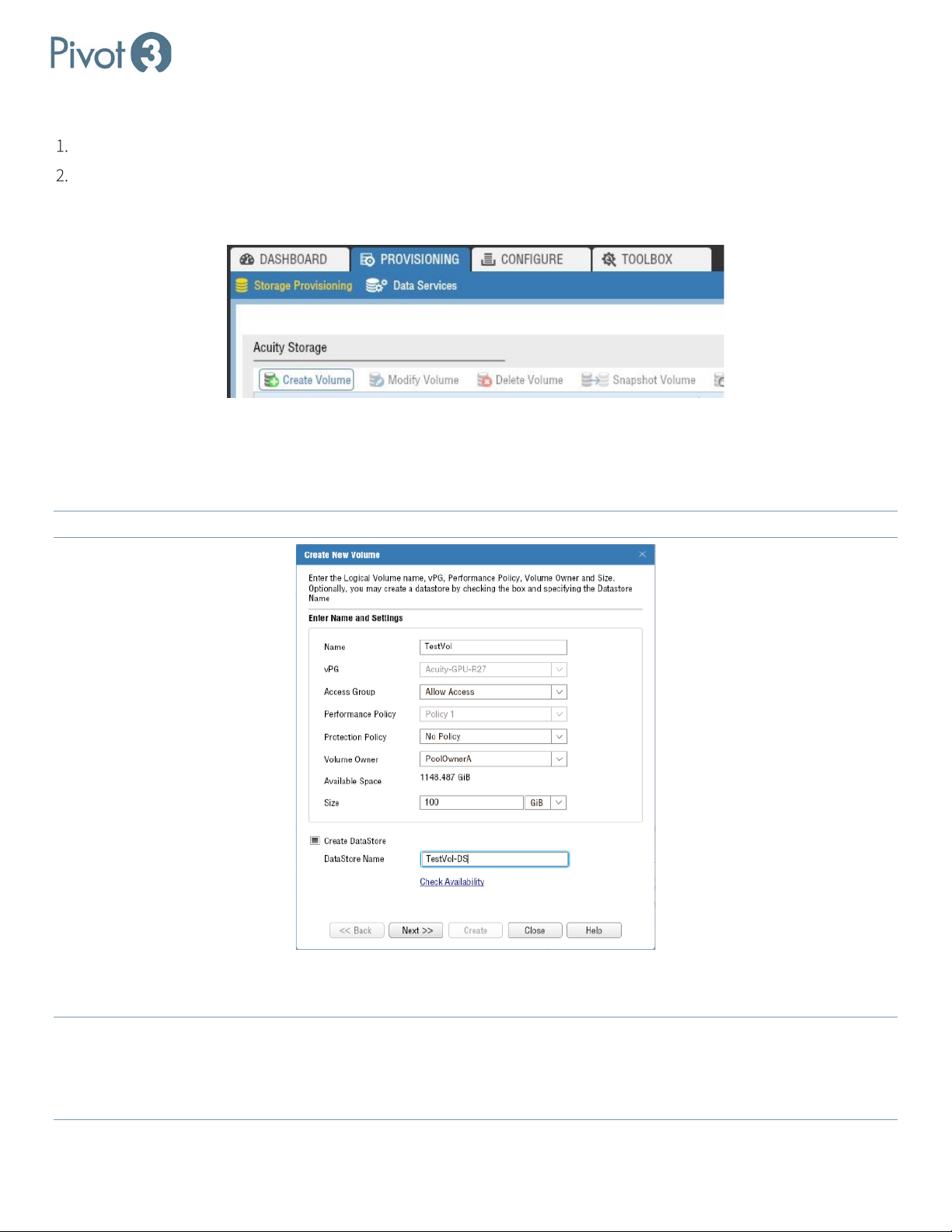
Setup & User Guide
Creating an Acuity Volume
If a Host Access Group has not been created, create one. Consult Section 10 for more information.
There are two ways to initiate the creation of an Acuity volume. The first is through the Provisioning tab.
a. On the Provisioning tab, go to the Storage Provisioning view. Under the Acuity Storage section, choose Create
Volume or the Performance QoS tab of the Data Services view.
b. This popup provides a dialog where details such as the Volume Name, associated vPG, Access Group,
Performance Policy, Protection Policy, and Volume Owner are required. The size of the volume is also determined
in this dialog. If the volume is intended to be used as a datastore, ensure Create Datastore has been checked and
Datastore Name has been entered. Click Next.
NOTE: The Check Availability
option will check all ESXi hosts to ensure a unique datastore name.
c. Confirm the details in the dialog and click Create to finalize the volume. Once the procedure is complete, the new
volume will be visible in the Acuity Storage list and can be modified.
NOTE: Volume and datastore names must be fewer than 40 characters and cannot contain any of the following characters:
\
' ; / { * } " : ~ % & @ + = < > ? ` _ ^ #
NOTE: This process can take a significant amount of time, depending on the number and configuration of ESXi hosts, network
connectivity, etc.
| 70
DOC-246-GDE-Pivot3 Acuity 2.3 Setup & User Guide-v1.0.docx
Page 71
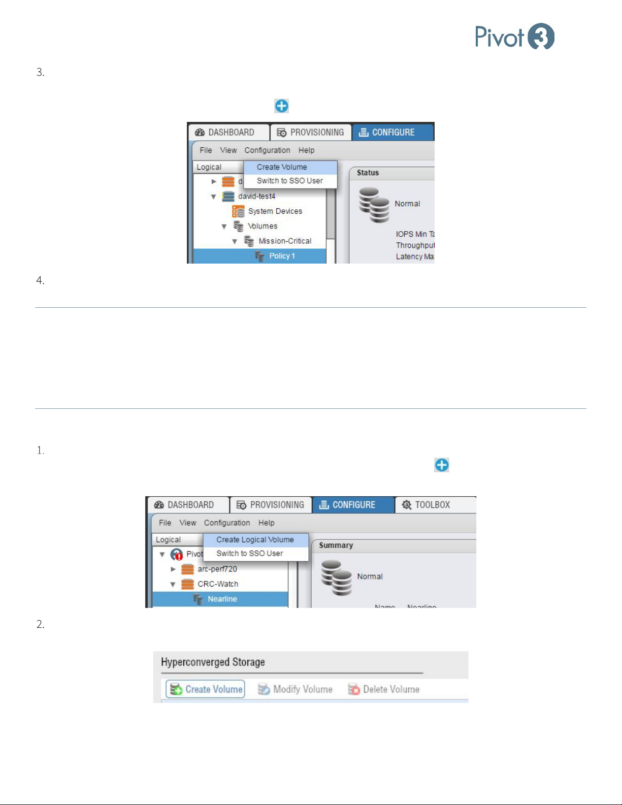
Setup & User Guide
The second way to create a volume is through the Configure tab’s Logical view.
a. On the Configure tab, click on the Policy level desired for the volume (as explained on p.47). Either choose
Configuration > Create Volume or click the in the top right of the menu bar.
Regardless of how the procedure is initiated, the same dialog box will pop up asking for volume details. Populate
these fields with the preferred settings.
NOTE: If volume creation has been initiated from the Policy level of the Configure tab, Performance Policy and vPG name will
already be chosen and cannot be altered.
NOTE: Volume names must be fewer than 40 characters, and cannot contain any of the following characters: \ ' ; / { * } " : ~
% & @ + = < > ? ` _ ^ #
NOTE:
This process can take a significant amount of time, depending on the number and configuration of ESXi hosts, network
connectivity, etc.
Creating a vSTAC Volume
vSTAC volumes are also supported in Pivot3’s Acuity software platform. In the Logical tree view of the Configure tab,
highlight the tier level and click Configuration > Create Logical Volume or click the in the top right of the menu
bar.
Alternatively, click Create Volume in the Hyperconverged Storage section of the Provisioning tab’s Storage
Provisioning view.
71 |
DOC-246-GDE-Pivot3 Acuity 2.3 Setup & User Guide-v1.0.docx
Page 72
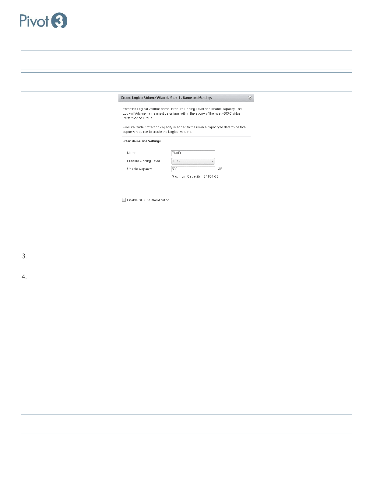
a. First, create the logical volume name (called Pivot3 in the example below).
Setup & User Guide
NOTE: Volume names must be fewer than 40 characters, and cannot contain any of the following characters:
\ ' ; / { * } " : ~
% & @ + = < > ? ` _ ^ #
NOTE: Datastores will be created using the default VMware configuration, datastore type VMFS5, utilizing all available
partitions as well as the entire Pivot3 volume capacity.
b. If desired, enable CHAP (Challenge Handshake Authentication Protocol) authentication. CHAP is an optional
security mechanism that allows network entities to perform additional authentication. If this box is checked, iSCSI
initiators must provide the correct CHAP secret when accessing the logical volume. If this box is not checked, no
CHAP secret will be required.
Click Next on the Create New Volume dialog box, review the information displayed, then click Create to complete
the volume creation process.
Assign the settings to the logical volume according to definitions below.
• Tier – Choose from the available SATA/SAS Tiers in the drop-down menu.
• Erasure Coding Level – Erasure Coding levels are unique to Pivot3 in that they are one step more efficient than
enhanced RAID, which are provided to meet the data protection goals of each application. Not all supported
Erasure Coding levels may be available due to node or drive failures, or available capacity constraints. Only the
Erasure Coding levels compatible with the current tier and volume will be displayed in the drop-down menu.
Acuity vPGs are supported by EC Level 3, which is enhanced striping with disk parity and protects up to 3
simultaneous disk failures or 1 disk and 1 node failure.
• CHAP Secret - If CHAP Authentication was selected in the previous screen, define or auto-generate it here.
• Usable Capacity – the amount of usable storage for the logical volume. Pivot3 Acuity solutions use “GB” and “TB”
30
to mean standards based on binary multiples of the byte. For example, 1GB is 2
bytes. 1TB is 240 bytes.
The minimum capacity for a logical volume is 1GB. Capacity must be specified in 1GB increments. The maximum usable
capacity is displayed under the Capacity text field and is updated when the EC Level is changed. Changing the EC level
updates the maximum usable capacity. The Next button will be enabled or disabled based on remaining capacity.
To dynamically expand capacity or change the EC level of a logical volume, these options are available in the
NOTE:
Configuration menu. Access Control for a volume may also be modified in this menu.
| 72
DOC-246-GDE-Pivot3 Acuity 2.3 Setup & User Guide-v1.0.docx
Page 73
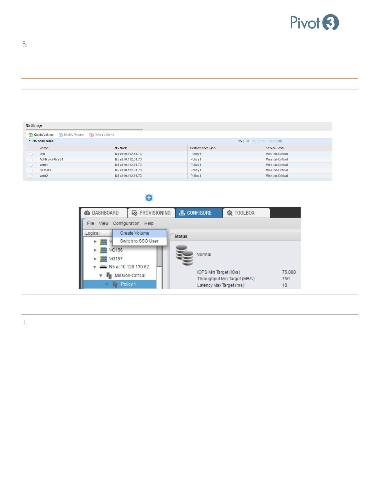
Setup & User Guide
At this time, both the volume and the datastore are created and configured based on the settings entered. Once the
process is complete, the dialog box will disappear.
Create an N5 Storage Volume
CRITICAL: An N5 Storage node must be added to the domain for this procedure to be possible.
N5 Storage volumes and Hyperconverged volumes differ in that they have been configured to run on different types of
hardware for separate purposes. Begin this procedure from the Dashboard tab, Storage Provisioning section. Click the
Create Volume option at the top left of the N5 Storage section.
N5 Storage Volume Creation can also be commenced from the Configure tab. With the Policy level selected, navigate to
Configuration > Create Volume or click the in the top right of the menu bar.
NOTE: For N5 Storage volumes created from the Configure
tab, the N5 Storage and Performance Policy settings will be
greyed out and not customizable.
Follow the instructions in the Create Volume dialog.
73 |
DOC-246-GDE-Pivot3 Acuity 2.3 Setup & User Guide-v1.0.docx
Page 74
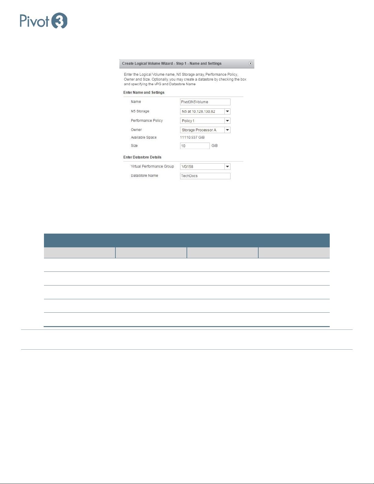
Setup & User Guide
Policy Number
Service Level
IOPS Target
Latency Target
a. First, create the logical volume name (called Pivot3N5Volume in the example below). The name must be unique
and comprised of 1-15 alphanumeric characters.
b. Choose the N5 Storage node to host this volume by IP. Only N5 nodes that have been properly added to the
domain will be available.
c. Assign the Performance Policy based on the definitions below. If the wizard was initiated from the Configure tab,
the Performance Policy will already be set and cannot be changed on this menu.
Performance Policy Service Levels Available
Policy 1 Mission Critical 100,000 5ms
Policy 2 Business Critical 50,000 10ms
Policy 3 Business Critical 20,000 25ms
Policy 4 Non-Critical 10,000 50ms
Policy 5 Non-Critical 2,000 100ms
NOTE: Prioritization of each policy may impact service levels below that policy. If more than ½ of the available performance is
provisioned to Mission Critical, the benefits of this feature may not be realized.
d. Next, choose a Storage Processor (A or B) to own the volume. Once a Storage Processor is selected, the available
capacity will automatically display. Enter the desired volume capacity in the text field.
e. To simultaneously create a Datastore during volume creation, click the checkbox next to Create Datastore and
choose the vPG for the Datastore from the drop-down, then enter a name in the field provided. Click Next to
continue.
| 74
DOC-246-GDE-Pivot3 Acuity 2.3 Setup & User Guide-v1.0.docx
Page 75
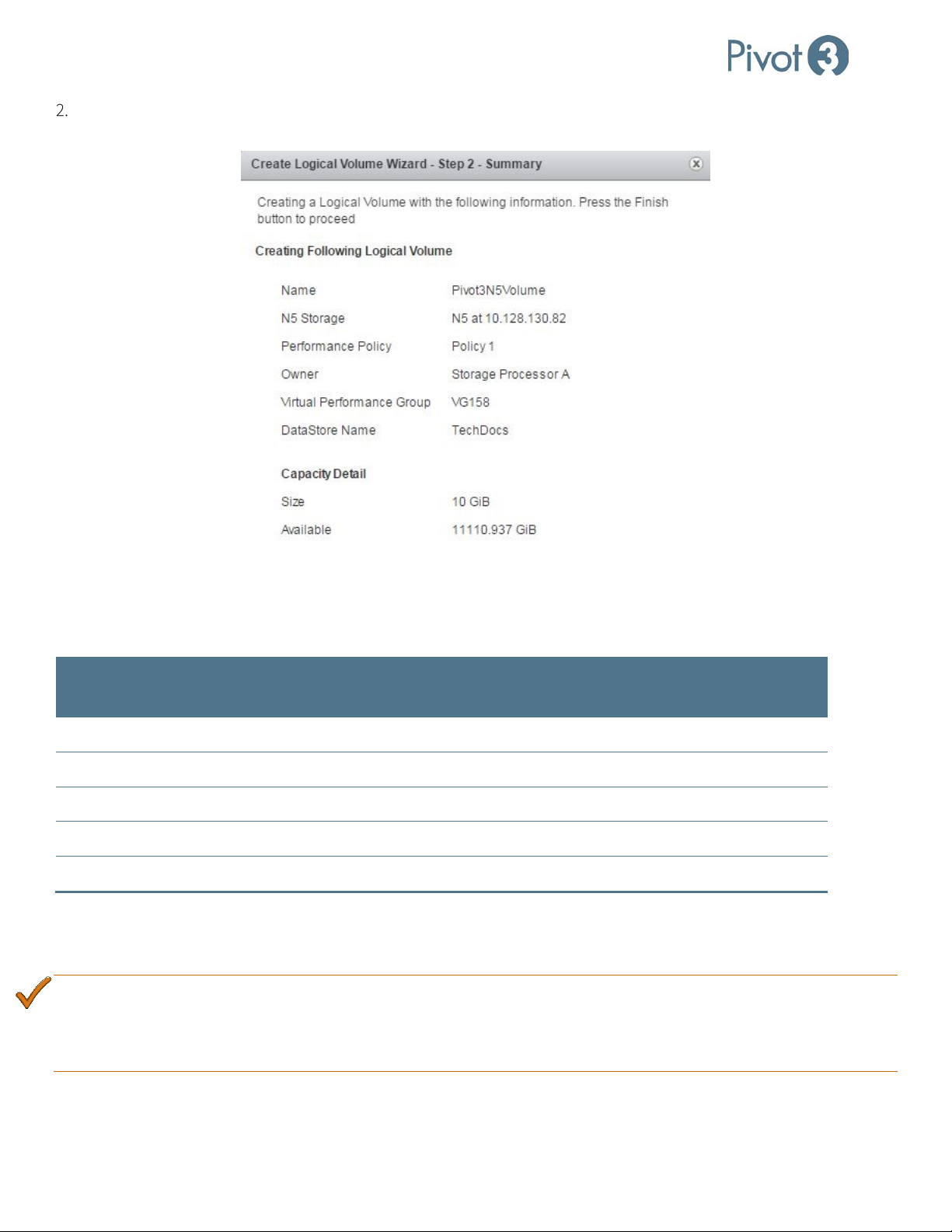
Setup & User Guide
Mission Critical
Business Critical
Non-Critical
Review the summary page and click Create to complete volume creation. To change any of the input, click Back to
edit settings.
Performance Policies
Performance policies are a way of associating specific performance parameters with volumes. There are five performance
policies. The table below summarizes the performance targets.
Service Level Policy Name
IOPS Min Target
(IO/s)
Policy 1 100,000 750 5
Business Critical
Policy 2 50,000 375 10
Policy 3 20,000 150 25
Policy 4 10,000 75 50
Non-Critical
Policy 5 2,000 38 100
To view the attributes of a specific performance policy, navigate to the Provisioning tab’s Data Services View and click
on the Performance QoS tab and choose the vPG in the upper-right corner of the screen. This view also shows the
number of volumes available for each Policy within the selected vPG.
BEST PRACTICE:
Carefully consider distributing volumes evenly across policies rather than assigning all of them to a single
policy. Configuring all volumes to the same policy negates Acuity’s ability to provide targeted performance
to a volume. This is especially important when volumes are provisioned by application in a mixed workload
environment.
Throughput Min
Target (MB/s)
Latency Max
Target (ms)
75 |
DOC-246-GDE-Pivot3 Acuity 2.3 Setup & User Guide-v1.0.docx
Page 76
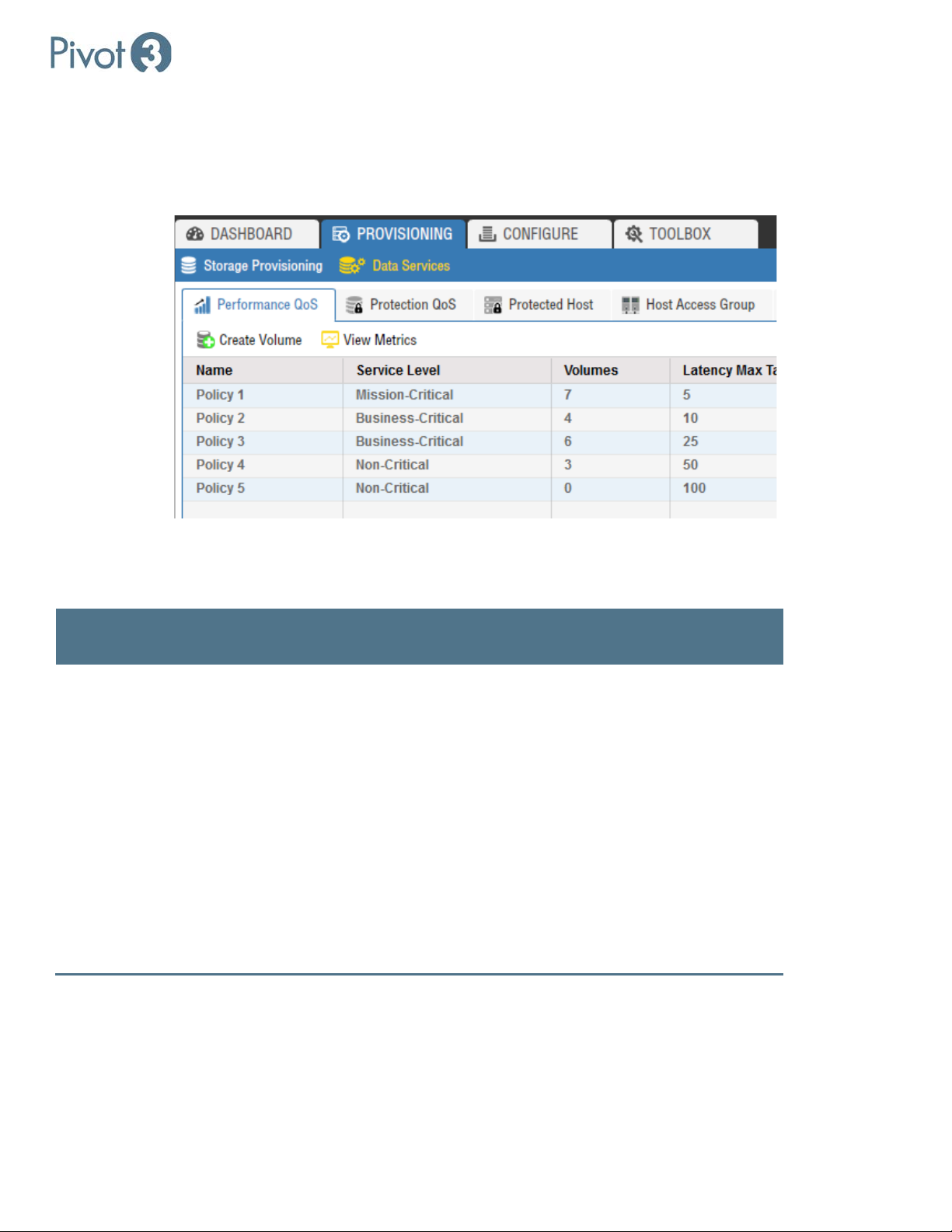
Setup & User Guide
Mission
spike above the service level targets.
•
Service Levels – Best Practices & Behavior
Service levels are a way to categorize the priority of applications. There are three service levels defined for Acuity and N5
volumes. Policies are assigned to the Mission Critical, Business Critical, and Non-Critical service levels in order of
performance priority.
Volumes assigned to the different service levels will have different behavior based on the current load and state of the
Acuity and N5 platforms. The enforcement of the performance policy targets is based on how the system responds in
different situations. Service levels guarantee performance to each application by isolating workloads from one another.
Service
Steady-state Behavior Degraded Behavior
Level
If the system is in a degraded state,
performance of Non-Critical and then
Business Critical volumes may be
impacted to meet the Mission Critical
service level.
Critical
• Volumes in the Mission Critical service
level receive the highest priority in the
system.
• If there is contention for performance
resources in the system, Mission Critical
volumes will receive a higher priority
for I/O processing.
• Performance of Non-Critical and then
Business Critical volumes may be
impacted to meet the Mission Critical
service level.
• If there are available resources in the
system, Mission Critical volumes may
| 76
DOC-246-GDE-Pivot3 Acuity 2.3 Setup & User Guide-v1.0.docx
Page 77

Setup & User Guide
Business
spike above the service level targets.
•
Non-
spike above the service level targets.
•
Service
Level
Critical
Critical
Steady-state Behavior Degraded Behavior
• Volumes in the Business Critical service
level receive the 2nd highest priority in
the system.
• If there is contention for performance
resources in the system, Business
Critical volume I/O will fall behind
Mission Critical volumes in priority.
• Performance of Non-Critical and then
Business Critical volumes may be
impacted to meet the Mission Critical
service level.
• If there are available resources in the
During a degraded state, Business
Critical volumes may take some of the
performance impact as required for
the system to continue to meet the
Mission Critical service level.
• Performance of Business Critical
volumes is “best-effort.”
• The system will impact the Non-
Critical volumes the most to attempt
to continue to meet the minimum
performance policy targets for
Business Critical volumes.
system, Business Critical volumes may
• Volumes in the Non-Critical service
level receive the lowest priority in the
system.
• If there is contention for performance
resources in the system, Non-Critical
volume I/O will fall behind Mission
Critical and Business Critical volumes
in priority.
• Performance of Non-Critical and then
Business Critical volumes may be
impacted to meet the Mission Critical
service level.
• If there are available resources in the
system, Non-Critical volumes may
During a degraded system, NonCritical volumes will take most of the
performance impact as required for
the system to continue to meet the
Mission Critical and Business Critical
service levels.
• Performance of Non-Critical volumes
is “best-effort”.
• The system will impact the Non-
Critical volumes the most to attempt
to continue to meet the steady-state
performance policy targets for Mission
Critical volumes and the minimum
performance policy targets for
Business Critical volumes.
BEST PRACTICE: Recommendations for assigning volumes to policies:
• Choose the highest priority applications and place the application volumes in Policy 1, Mission Critical service level.
• Do not assign all the volumes to Policy 1 as this will simply mean that all I/O is treated equally by the system. There
will be no real prioritization of I/O through the system.
• Typically, most customers have 20% of their volumes in the Mission Critical service level, 30-40% of their volumes in
Business Critical and the remaining volumes in Non-Critical.
• Applications that require low latency I/Os should be in either Policies 1 or 2. Applications that require low latency are
transaction based, like OLTP (online transaction processing) databases.
• Applications that are not as latency-sensitive should be placed in Polices 3, 4 or 5. Applications that fall into this
category are collaboration / file share type applications.
77 |
DOC-246-GDE-Pivot3 Acuity 2.3 Setup & User Guide-v1.0.docx
Page 78
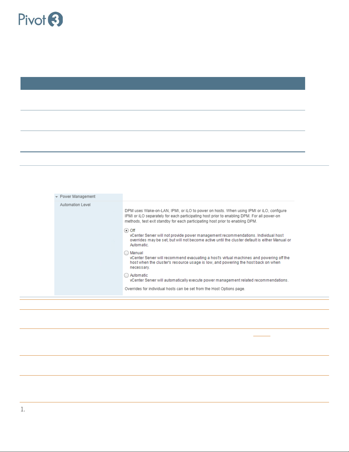
Setup & User Guide
Acuity ESXi Hosts and Maintenance Mode
Before an ESXi host goes into Maintenance Mode, its guest VMs must be migrated to a different host. The cluster type
where the host resides can affect the procedure this follows. The table below explains the configurations and their
migration processes, as well as specific user actions if applicable.
ESXi Host’s Cluster Type Host Migration Procedure
vSphere DRS-protected cluster
Cluster without vSphere DRS
protection
Not a member of a cluster User must manually shut down all guest VMs on the Acuity ESXi host or
To enable DRS protection, select the ESXi cluster and navigate to Configure tab > Services > vSphere DRS.
NOTE: If the Power Management’s Automation Level is set to Automatic
Power off if the vPG is shut down from the Plugin.
Pivot3 recommends leaving the Power Management Automation Level setting to Off.
vCenter will automatically use vMotion to migrate all guest VMs on the
Acuity ESXi host to another member of the cluster.
User must manually shut down all guest VMs on the Acuity ESXi host or
migrate them to another member of the cluster.
migrate them to another Acuity ESXi host.
in vCenter, the hosts may enter Standby Mode and
CRITICAL: Never move a Pivot3_VM. It is tied to the host and must not be migrated.
Adding ESXi Hosts & Datastores
CRITICAL: When adding a new host to a vPG, configure the iSCSI adapter with the new alias before adding the host to
the vPG. If the iSCSI alias or name is configured after the node has been added to the vPG, a manual rescan will be
required to see the new datastore from the new host.
For vPGs With vSTAC Storage
CRITICAL: When adding a new host to a vPG, configure the iSCSI adapter with the new alias before adding the host to the
vPG. If the iSCSI Alias is configured after the node has been added to the vPG, a manual rescan will be required to
see the new datastore from the new host.
Log in to vCenter Web Client on the new host and update the host’s iSCSI Alias.
| 78
DOC-246-GDE-Pivot3 Acuity 2.3 Setup & User Guide-v1.0.docx
Page 79
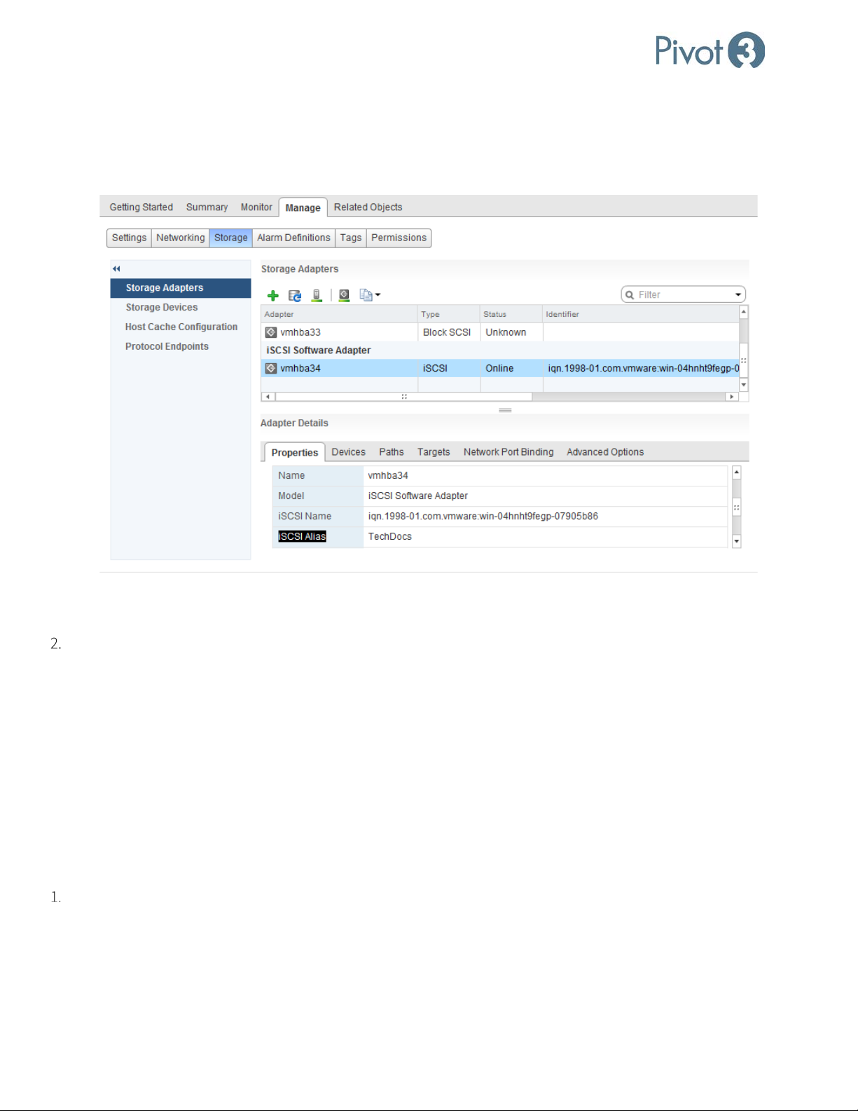
Setup & User Guide
a. Navigate to Home > Hosts and Clusters.
b. Select the new ESXi host in the Navigator panel and navigate to Manage > Storage > Storage Adapters.
c. Locate the iSCSI software adapter section and click on the vmhba.
d. The web client lists the ESXi host’s iSCSI Alias in the General section within the vmhba’s Properties panel.
e. To modify or add the iSCSI Alias, click on the Edit button on the General header row and enter the desired Alias
name in the popup.
Log in to the vCenter Web Client Pivot3 Plugin and use the Modify Membership wizard to add the new vSTAC node to
the vPG.
a. If the new ESXi host already has an iSCSI Alias, the vPG modification process will automatically add the
necessary iSCSI addresses to the host’s Dynamic Discovery list, and the software will automatically start a storage
rescan on the ESXi host.
b. If the iSCSI Alias is added before the host is added to the vPG, the datastore will show up automatically
without further user intervention.
c. If the iSCSI Alias is added after the host is added to the vPG, a manual storage rescan on the ESXi will be
required after the new ESXi host is added to the vPG.
For vPGs with Acuity Storage
Log in to the vCenter Web Client on the new host and locate the host’s iSCSI Name.
a. Navigate to Home > Hosts and Clusters.
b. Select the new ESXi host in the Navigator panel and navigate to Manage > Storage > Storage Adapters.
c. Locate the iSCSI software adapter section and click on the vmhba.
d. The web client lists the ESXi host’s iSCSI name in the details within the vmhba’s Properties panel.
79 |
DOC-246-GDE-Pivot3 Acuity 2.3 Setup & User Guide-v1.0.docx
Page 80

Setup & User Guide
Log in to the vSphere Web Client Pivot3 Plugin.
a. Navigate to Provisioning > Data Services > Host Access Group.
b. Select the Host Access Group associated with the volume(s) backing the applicable datastore(s) for the vPG.
c. Modify the selected Host Access Group and add the iSCSI Name found in step 1d.
Use the Plugin’s Modify Membership wizard to add the new Acuity-based X5 node to the vPG. The vPG modification
process will automatically add the necessary iSCSI addresses to the host’s iSCSI software adapter, and the software
will automatically start a storage rescan on the ESXi host.
For vPGs with N5 Storage
Log in to vCenter Web Client on the new host and locate the host’s iSCSI Name.
a. Navigate to Home > Hosts and Clusters.
b. Select the new ESXi host in the Navigator panel and navigate to Manage > Storage > Storage Adapters.
c. Locate the iSCSI software adapter section and click on the vmhba.
d. The web client lists the ESXi host’s iSCSI Name in the details within the vmhba’s Properties panel.
In the vCenter Web Client, add the N5 SAN addresses to the host’s Dynamic Discovery list.
a. Navigate to Home > Hosts and Clusters.
b. Select the new ESXi host in the Navigator panel and navigate to Manage > Storage > Storage Adapters.
c. Locate the iSCSI software adapter section and click on the vmhba.
d. Select the Targets tab.
e. Select the Dynamic Discovery tab and press Add.
f. One at a time, enter all SAN addresses for the N5 node in the box labeled iSCSI Server.
Log in to the N5 Web Application.
a. Navigate to Provision > Host Access Groups.
b. Select the Host Access Group associated with the volume(s) backing the applicable datastore(s) for the vPG.
c. Modify the selected Host Access Group and add the iSCSI name found in step 1d.
In the vSphere Web Client Pivot3 plugin, use the Modify Membership wizard to add the new Acuity-based node to the
vPG.
Perform a manual rescan of the ESXi hosts, and the new datastore should be visible.
BEST PRACTICE: To remove a ghosted datastore, shut down all associated VMs and reboot the affected host.
| 80
DOC-246-GDE-Pivot3 Acuity 2.3 Setup & User Guide-v1.0.docx
Page 81

Setup & User Guide
Section 12 Snapshot Management
This chapter describes how to protect data using snapshots of volumes to create recovery points. This can be done on an
individual-volume level (manually or using schedules) or with policies to protect groups of volumes. The Data Protection
Quality of Service feature uses policies − named collections of up to three scheduled tasks − to easily apply sets of tasks to
multiple volumes.
CRITICAL:
Servers that are not added to the Protected Host list, with refreshed associations run, will not be configured to take
host-consistent snapshots.
Snapshots Overview
A SAN-based snapshot is an image of a disk at a specific point in time. Snapshots allow for basic recovery functions and
can be converted into new volumes as needed. The Protected Hosts feature allows for host consistent snapshots of
volumes on ESXI and Microsoft Windows using the Volume Shadow Copy Service (VSS) Provider.
Snapshots are thin provisioned, and as the active volume changes, previously unreferenced blocks will be kept as part of
the last snapshot. Over time, the oldest snapshot will take up additional space, with a maximum equivalent to the size of
the volume at the time the snapshot was taken.
BEST PRACTICE: Use ESXi iSCSI storage instead of guest-mounted storage.
sessions will occasionally lose connectivity while VMware pauses the VM.
NOTE: Snapshots are not meant to replace primary backup methods.
SAN-based snapshots can be useful in the following situations:
• Snapshots can be created right before the upgrade of a system to provide an additional backup mechanism for the
environment.
• Cloned snapshots provide a mechanism to perform development or testing scenarios on an exact copy of data
without affecting production data.
Datastore snapshots on guest-mounted iSCSI
Types of Snapshots
• Host Consistent: These snapshots are coordinated with the protected host to quiesce I/O before taking a snapshot,
and there is a much better chance of recovering from this type of snapshot. The Pivot3 vCenter Plugin defaults to this
type of snapshot whenever possible; if not, it relegates to Crash Consistent.
• Crash Consistent: These snapshots are not negotiated but taken at the exact moment of request, without quiescing
I/O.
NOTE: If there is not enough space on the vPG to generate a snapshot, the schedule or task returns an error:
invalid snapshot configuration. Configure datastores and virtual disks as thin provisioned to help avoid this issue.
CRITICAL: Snapshots of datastore volumes that contain a VM using Raw Device Mapping will not be host-consistent.
Detected an
Before Creating a Snapshot on Other Operating Systems
To take a restorable, host-consistent snapshot of other operating systems, the file system must be quiesced and then
synchronized before the snapshot is taken. No I/O can be running during this procedure.
81 |
DOC-246-GDE-Pivot3 Acuity 2.3 Setup & User Guide-v1.0.docx
Page 82

Setup & User Guide
Protected Hosts
Protected Hosts are ESXi Servers and Windows Servers hosting volumes on Acuity. The implementation of Protected
Hosts allows customers to create snapshots that are properly quiesced from the perspective of the operating system and
applications running on Acuity volumes.
CRITICAL:
Protected Hosts attempt to generate host consistent snapshots. If the host can’t quiesce IO, it will retry three times,
then take a crash consistent snapshot.
The ESXi Servers hosting Data Stores and VMFS volumes on Acuity are eligible for host consistent snapshots. Pivot3 works
with the ESXi API to accomplish the task.
Windows servers are eligible for host consistent snapshots if the Pivot3 VSS provider is installed. The Provider works with
Windows VSS Providers and Windows Writers to quiesce I/O on the server to accomplish the task.
NOTE:
Servers should have volumes configured for use before adding the Protected Host. Windows servers must have the
Pivot3 VSS Provider installed and authenticated.
To Add a Protected Host, click Add Protected Host and provide the following details:
Name Enter a descriptive name for the host.
Username Enter a username for a user on the host.
Password Enter a password for the user.
Retype Password Re-enter the password for the user.
Address Enter an IP address for the host.
Port (optional) Enter a specific port, if necessary.
Volume Shadow Copy Service (VSS)
The Volume Shadow Copy Service (VSS), introduced in Windows Server 2003, is a set of COM interfaces that implements a
framework to allow volume snapshots to be performed while applications on a system continue to write to the volumes.
rd
NOTE: Certain types of 3
the vPG. Once the failed node is restored, the 3rd party backups will complete successfully.
VSS allows applications to quiesce data prior to creating a snapshot. This framework allows for backup application to
utilize the ioControl feature of storage-based snapshots.
A high-level overview of the steps in the VSS process is described below:
The requestor creates a backup.
The writer quiesces the application to the volume.
The provider takes the snapshot.
Install the VSS Provider
Download and install the Pivot3 VSS provider install package.
Execute the install package on the Windows Client Servers.
party backups, when using the VSS provider, may fail if one of the Accelerated nodes is failed out of
| 82
DOC-246-GDE-Pivot3 Acuity 2.3 Setup & User Guide-v1.0.docx
Page 83
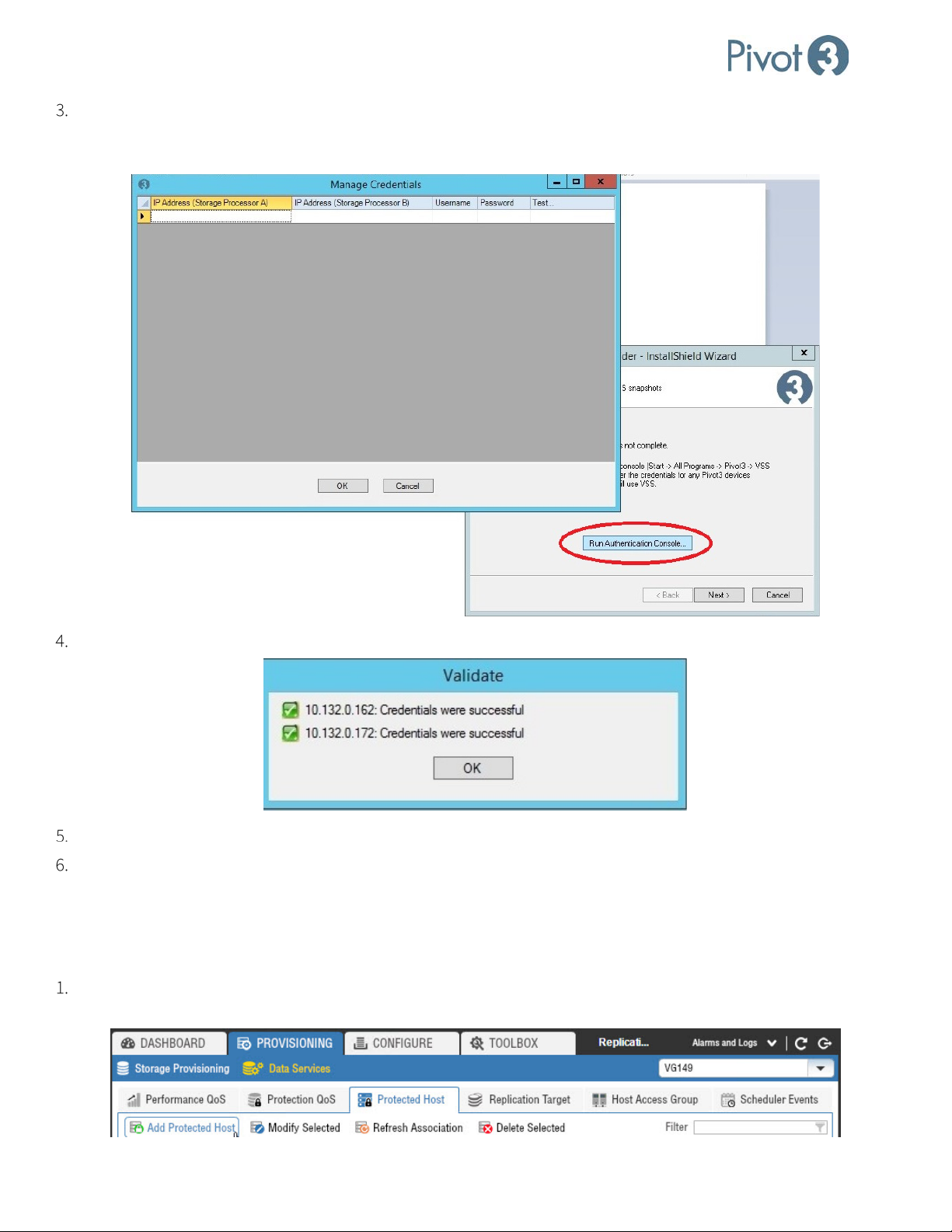
Setup & User Guide
Follow the wizard to the Install step. After clicking Install, run the Authentication Console by clicking the Run
Authentication Console button. Provide the Pivot3 Management IPs and Administrative user authentication for both
accelerated nodes and click OK.
Validate the Authentication Settings.
Select OK to exit the Authentication Console and Finish to close the wizard.
To open the VSS Provider Authentication Console after the installation has completed, navigate to
C:\ProgramFiles\Pivot3\VSS Provider\AuthConsole.exe. Execute the file to set and validate the
Management Credentials as needed.
Add a Protected Host - Pivot3 vCenter Plugin
Log in to the plugin. Navigate to Provisioning tab > Data Services view > Protected Host tab. Select a vPG and click
Add Protected Host.
83 |
DOC-246-GDE-Pivot3 Acuity 2.3 Setup & User Guide-v1.0.docx
Page 84
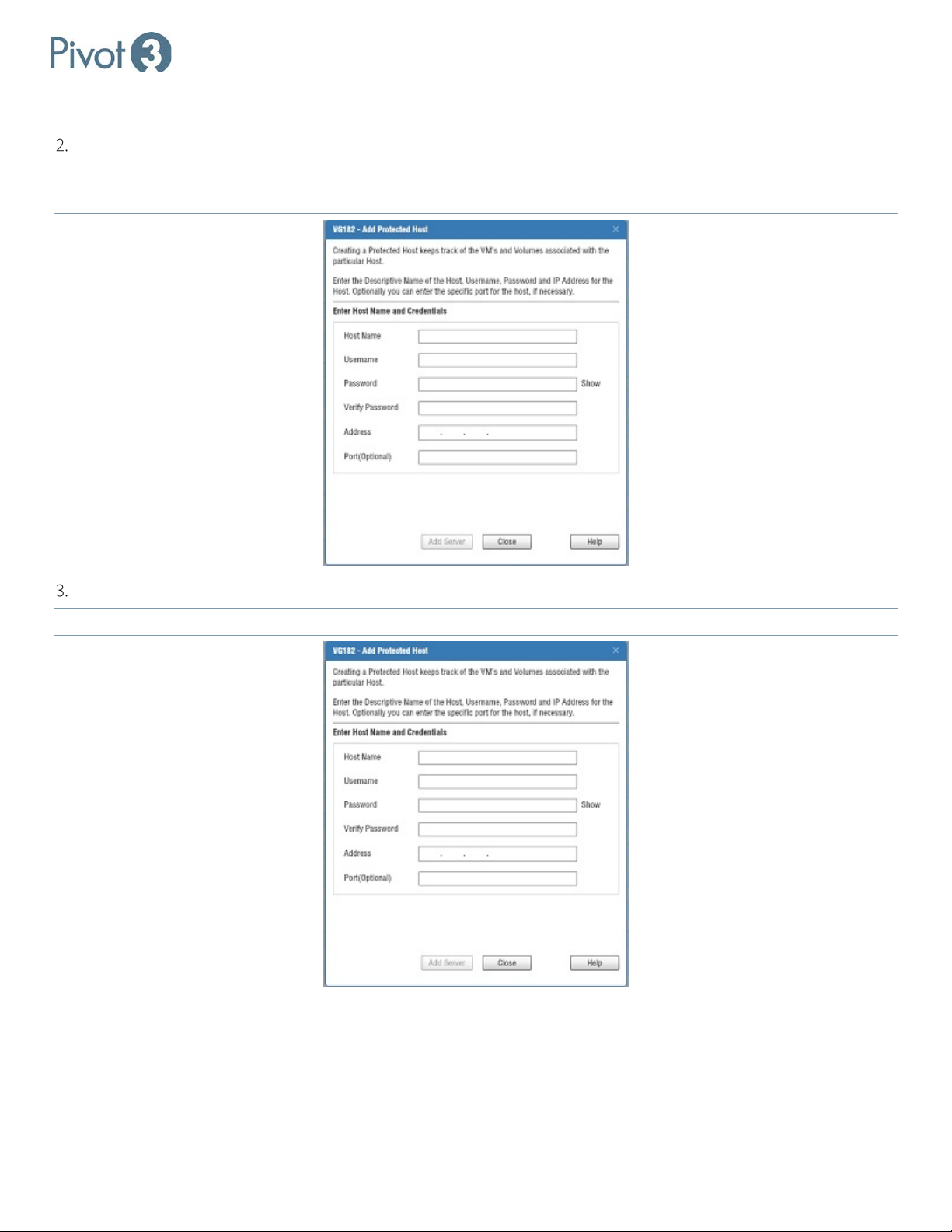
Setup & User Guide
Add a Server as a Protected Host, providing its Management IPs and Administrative credentials. Provide the Server’s
Management IP and Administrative credentials.
NOTE: When the server is added, authentication will complete and the host will be added.
To add the Pivot3 vCenter Server / Client, provide its Management IPs and the Administrative user credentials.
NOTE: When the client is added, users may access the VMs hosted on the Pivot3 node.
| 84
DOC-246-GDE-Pivot3 Acuity 2.3 Setup & User Guide-v1.0.docx
Page 85
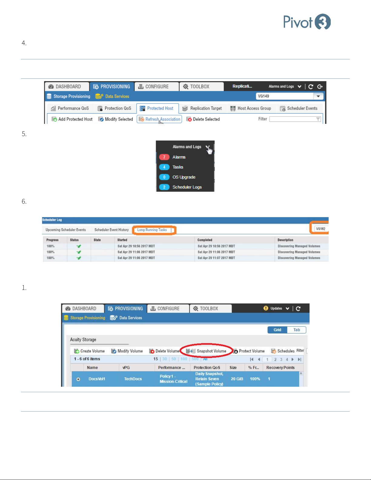
Setup & User Guide
Click Refresh Association. Volume-to-Server associations are discovered and the association is persisted. This
generates a Long-Running Task to Discover Managed Volumes.
NOTE: When Protected Hosts are added, Refresh Association runs automatically.
If changes are made to volume
assignments, this needs to be run manually to update the Volume-to-Server associations.
To view Long Running Tasks, drop down the Alarms and Logs tab and select Scheduler Logs.
Select vPG and select Long Running Tasks to see the various scheduled tasks that have been attempted and/or
completed. More information on this is available in sub-section
Creating a Manual Snapshot
To create a snapshot of a volume, navigate to the Provisioning tab’s Storage Provisioning view. Click the radio
button next to the volume to receive a snapshot and click Snapshot Volume.
NOTE:
Retention on a schedule does not apply to manual snapshots. If a snapshot is taken manually, it must be deleted
manually. Manual snapshots are not included in the retention count.
85 |
DOC-246-GDE-Pivot3 Acuity 2.3 Setup & User Guide-v1.0.docx
Page 86
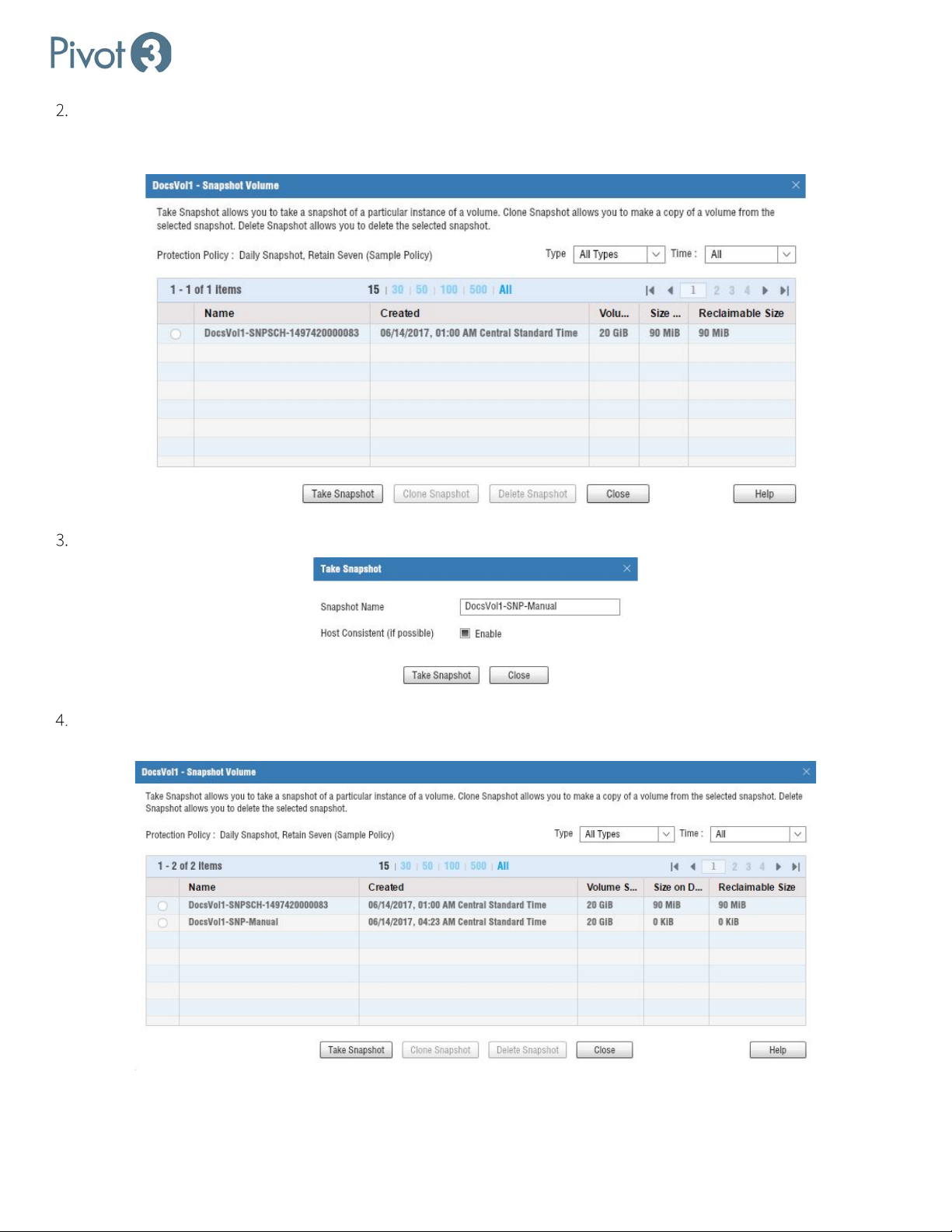
Setup & User Guide
The dialog expands to include snapshot parameters. If there are any existing snapshots, they will show up here and
can be cloned or deleted when selected. To create a new manual snapshot, simply click
Take Snapshot at the
bottom of the dialog box.
Rename the snapshot if desired, and ensure Host Consistent (if possible) is Enabled. Click Take Snapshot.
A popup will confirm if the snapshot is successful. Note that the snapshot may not immediately show up in the list;
this is expected behavior.
| 86
DOC-246-GDE-Pivot3 Acuity 2.3 Setup & User Guide-v1.0.docx
Page 87
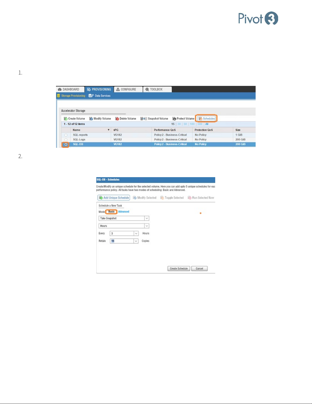
Setup & User Guide
Schedules on a Volume or an Application Group
Schedules are set on a volume and only apply to that volume, unless there is an application with a writer to define the
volume association between multiple volumes on the Server. Snapshots, Replications, and Performance Policy changes
can be scheduled and monitored in Long Running Tasks.
Log in to the Web plugin and open the Provisioning tab, Storage Provisioning view. Select the radio button next to
the desired volume and click Schedules.
Select Add Unique Schedule – Basic to create a basic schedule to run at a time interval chosen by the administrator.
In this example, a Snapshot will be performed every 3 hours and the system will retain 16 copies before removing the
oldest snapshot.
87 |
DOC-246-GDE-Pivot3 Acuity 2.3 Setup & User Guide-v1.0.docx
Page 88
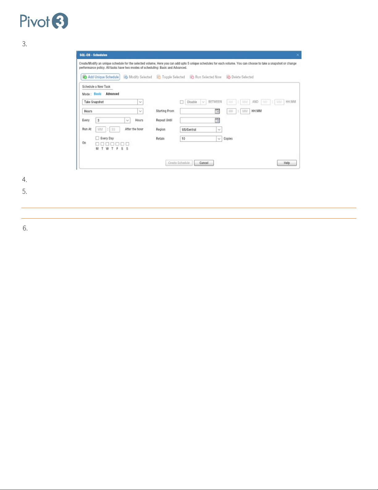
Setup & User Guide
Other options:
Modify Selected
Modification changes will be persisted and will run as scheduled.
Toggle Activation
Toggle allows users to pause and resume schedule execution without making
other changes.
Run Selected Now
scheduled time.
Delete Selected
Delete will remove the schedule, but not the snapshots it created.
The Advanced schedule mode provides more options to allow users to refine schedules.
Click Create Schedule. The schedule will be created and can be viewed on the Schedules tab.
Retention is set on a scheduled task. If there are multiple schedules on a volume, each schedule can have its own
retention setting and more snapshots may be maintained than originally perceived.
CRITICAL: The retention setting only applies to snapshots from that schedule.
This command will execute the schedule now, then will continue to execute at the
Protection Policies Explained
The Acuity Data Protection Policy feature uses policies to protect multiple volumes systematically. A policy is a named
collection of up to three scheduled tasks that can be applied to multiple volumes (without having to enter all the details
for each volume).
Schedule tasks within the policies carefully. Throughput and time spent completing the tasks are optimized by
sequencing a few jobs at a time and not scheduling them to kick off all at the same time.
To view, add, or change policies, navigate to the Provisioning tab > Data Services View > Protection QoS tab.
Working with Protection Policies
The Actions menu on the Protection QoS tab allows for policies to be added, modified, activated or deactivated, run, or
deleted.
Each policy can have up to three tasks, which can be either snapshots or replications. Each task has a basic and an
advanced mode. For more information on configuring tasks, see Snapshots Overview.
| 88
DOC-246-GDE-Pivot3 Acuity 2.3 Setup & User Guide-v1.0.docx
Page 89
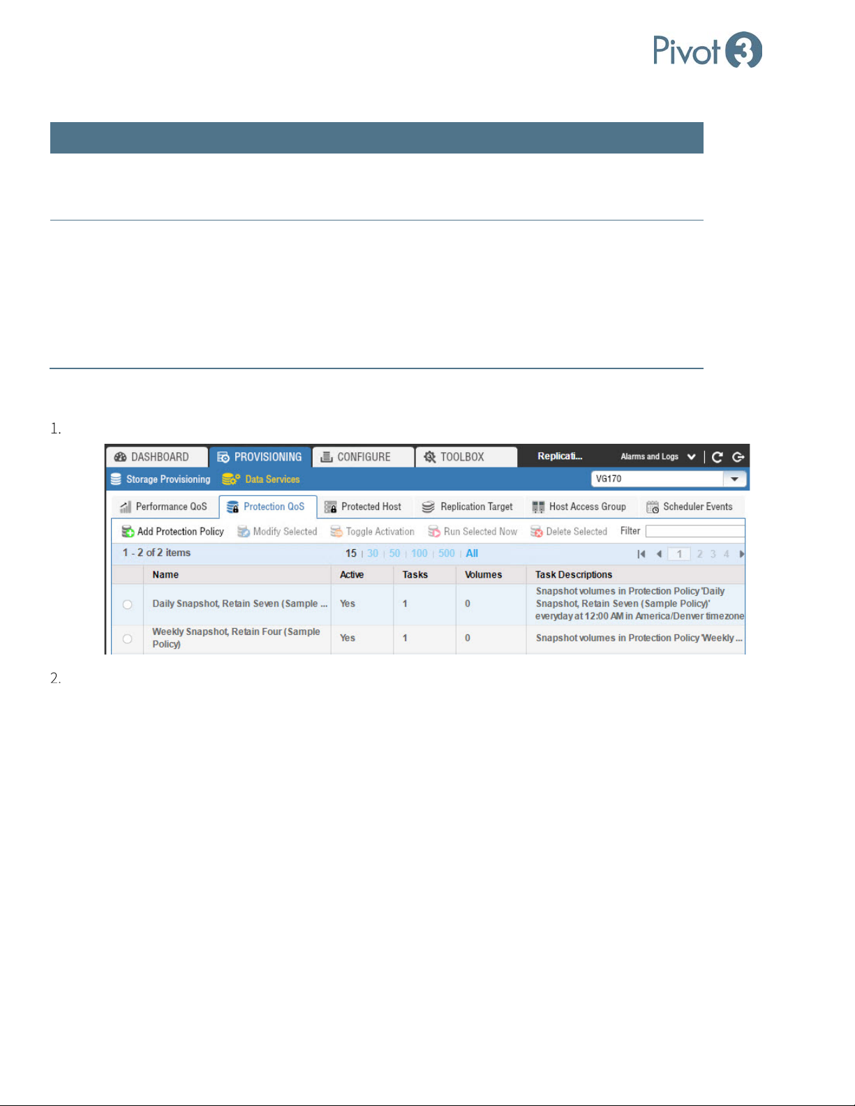
Setup & User Guide
Creating snapshots
quiescing of a single database at a time, rather than all volumes.
Protection Policy Best Practices Summary
Item Best Practice
Load balancing Create multiple policies, carving our smaller sections of work, so that the work
can be spread out. Tasks should be balanced across the day, factoring in IO
load, number of volumes processed, how much data is to be processed, etc.
of Exchange Data
Access Groups
(DAGs)
host-consistent snapshots of DAGs, use a protection policy:
— Verify that the VSS provider is installed on the Exchange servers
— Create a policy to snapshot or replicate as needed
— Assign the policy to the DAG volumes
• Best practice is to set individual policies for each DAG. This allows
Creating a Custom Policy
From Provisioning tab > Data Services view > Protection QoS tab, click Add Protection Policy.
• Exchange does not identify DAGs as an application group. To approximate
The Add Protection Policy dialog opens. Within this dialog, there are two views: Basic and Advanced.
89 |
DOC-246-GDE-Pivot3 Acuity 2.3 Setup & User Guide-v1.0.docx
Page 90
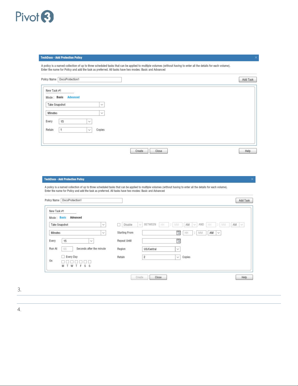
Setup & User Guide
a. The Basic view provides options regarding Type of task (Take Snapshot), Time Period (Minutes, Hours, Days,
Weeks, or Months), Increment (Changes based on Period of Time selected), and Retention instructions (how many
copies to retain of this snapshot; the options are 1-50 and Unlimited).
b. The Advanced view provides similar options but with much more granular variables so that administrators may
have more control over the scheduled tasks.
In either view, simply choose the preferred variables and then click Create.
NOTE: The Create
option will be disabled until all required variables have been defined.
A pop-up dialog will confirm the creation of the new Protection Policy, and it will now show up in the list in
Provisioning tab > Data Services > Protection QoS tab.
| 90
DOC-246-GDE-Pivot3 Acuity 2.3 Setup & User Guide-v1.0.docx
Page 91
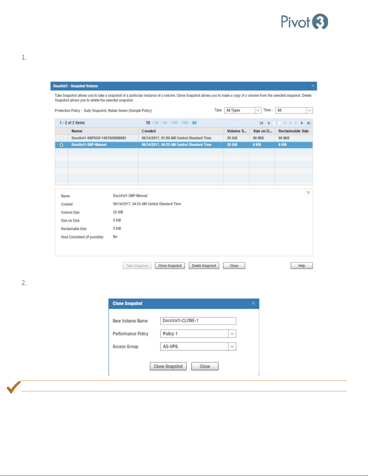
Setup & User Guide
Clone a Snapshot
Navigate through the same Provisioning > Storage Provisioning View > Select Volume > Take Snapshot route
used to create a snapshot, select the snapshot to be deleted or cloned from the options available, and the screen will
change to provide these options.
The Clone Snapshot option will provide an opportunity to modify the clone volume’s name, Performance Policy, and
Access Group.
BEST PRACTICE: Provide a custom Access Group instead of the default. Allow Access is strongly discouraged
.
91 |
DOC-246-GDE-Pivot3 Acuity 2.3 Setup & User Guide-v1.0.docx
Page 92
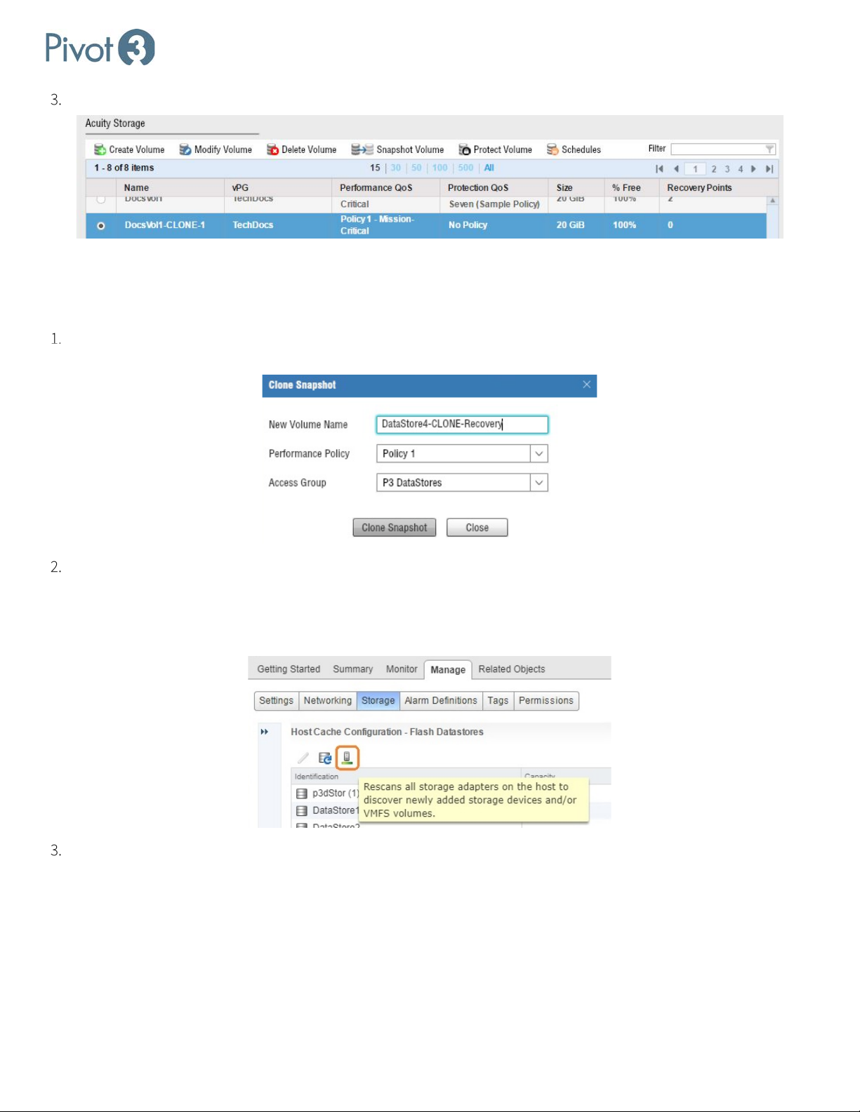
Setup & User Guide
Once the clone has been created, a new volume will be visible in the Storage volume list.
Recovering a Snapshot
ESXi
Select a snapshot to clone from Provisioning > [Select a volume] > Snapshot Volume > [Select a Snapshot] >
Clone Snapshot.
Rescan storage from the vSphere Web Client.
a. Navigate to Home > Hosts and Clusters.
b. Select the new ESXi host in the Navigator panel and navigate to Manage > Storage > Host Cache Configuration.
Click the Rescan icon.
Add the new Datastore.
a. Navigate to Home > Hosts and Clusters.
| 92
DOC-246-GDE-Pivot3 Acuity 2.3 Setup & User Guide-v1.0.docx
Page 93
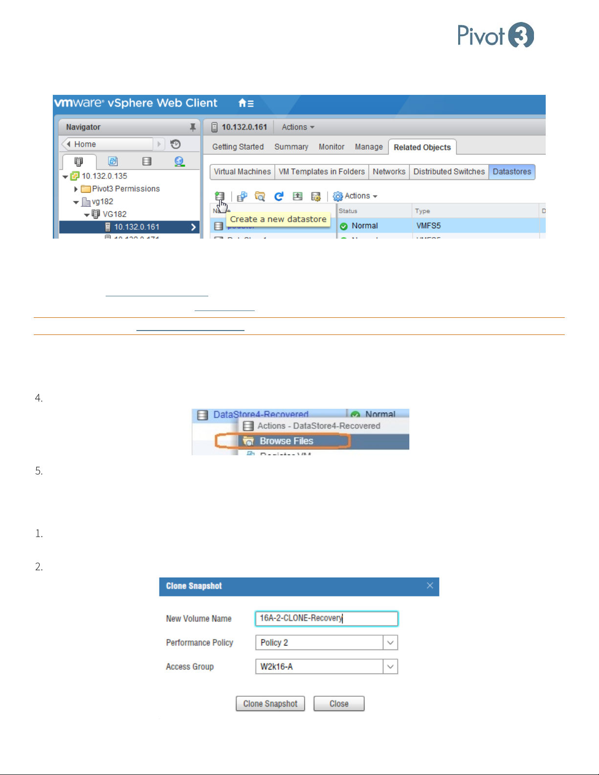
Setup & User Guide
b. Select the ESXi host in the Navigator panel and navigate to Related Objects > Datastores. Click the New
Datastore icon.
c. For Type, select the radio button next to VMFS. Click Next.
d. VMware will automatically name the new Datastore; change this name as desired and click Next.
e. Choose Assign a new signature (recommended) or Format the disk
if desired. More information on the different
mount options are available from VMware. Click Next.
CRITICAL: Using option Keep existing signature can occasionally cause unpredictable results and is not recommended.
f. Review the details on the summary page and click Finish to complete.
g. The volume clone will now be visible in the Related Objects > Datastores view. VMware will provide a default
string; rename the clone to something more meaningful.
Right-click on the volume clone and click Browse Files.
This will change the view to a screen with the contents of the restored snapshot. The recovered data can now be
deleted, moved, copied, or cloned repeatedly.
Windows
Select a snapshot to clone from Provisioning > [Select a volume] > Snapshot Volume > [Select a Snapshot] >
Clone Snapshot.
Edit the clone’s Name, Performance Policy, and Access Group if desired.
93 |
DOC-246-GDE-Pivot3 Acuity 2.3 Setup & User Guide-v1.0.docx
Page 94
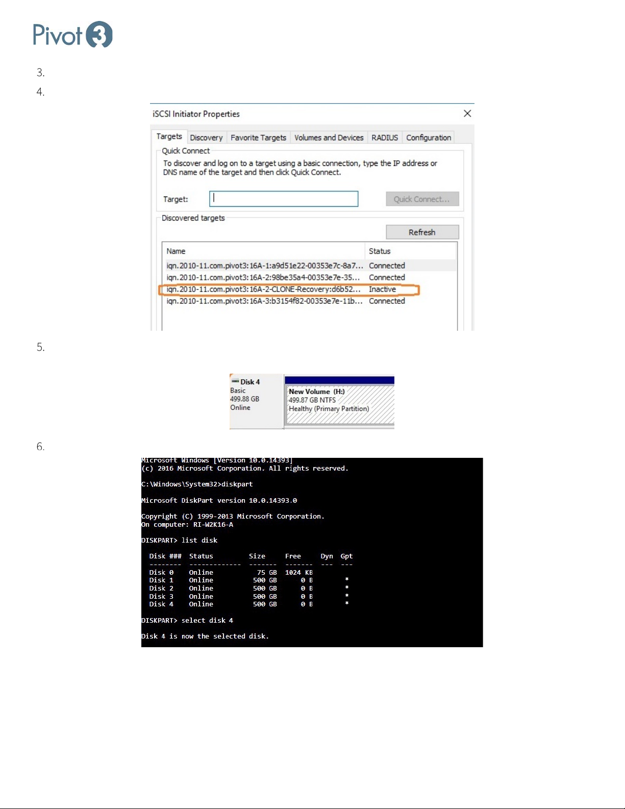
Setup & User Guide
The clone is created and will now show up as a new volume.
Discover the new volume and log in via iSCSI Initiator. The new volume will initially show up as Inactive.
Open Computer Management > Storage > Disk Management and bring the new disk online. The disk will be
recognized as it is formatted; it may be necessary to assign a drive letter.
Open a command prompt and run diskpart to select the correct disk.
| 94
DOC-246-GDE-Pivot3 Acuity 2.3 Setup & User Guide-v1.0.docx
Page 95
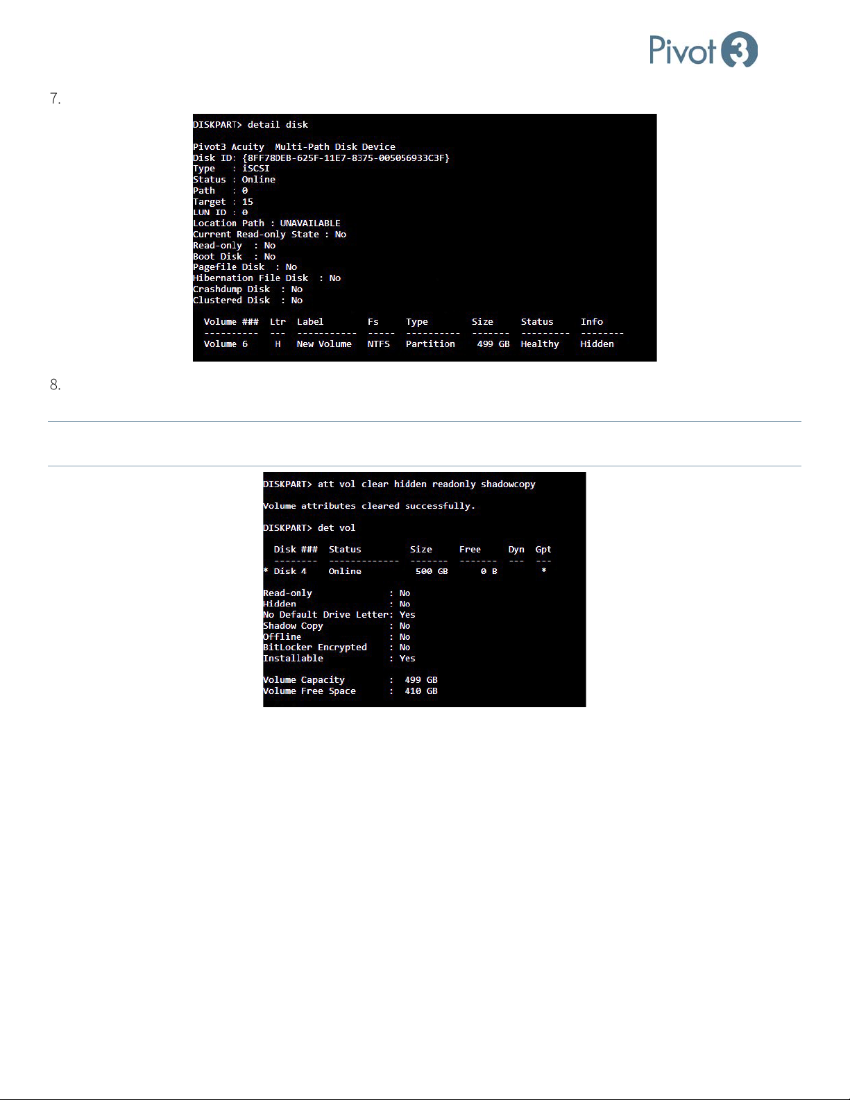
Setup & User Guide
Get details on the disk and identify the volume associated with the clone.
Clear hidden, readonly, and shadowcopy attributes on the volume with the command att vol clear hidden
readonly shadowcopy. Then run details on the volume to verify this has been done.
When a Windows snapshot is cloned, these cloned attributes must be removed before the clone is fully functional. Use
NOTE:
diskpart to remove those attributes.
95 |
DOC-246-GDE-Pivot3 Acuity 2.3 Setup & User Guide-v1.0.docx
Page 96
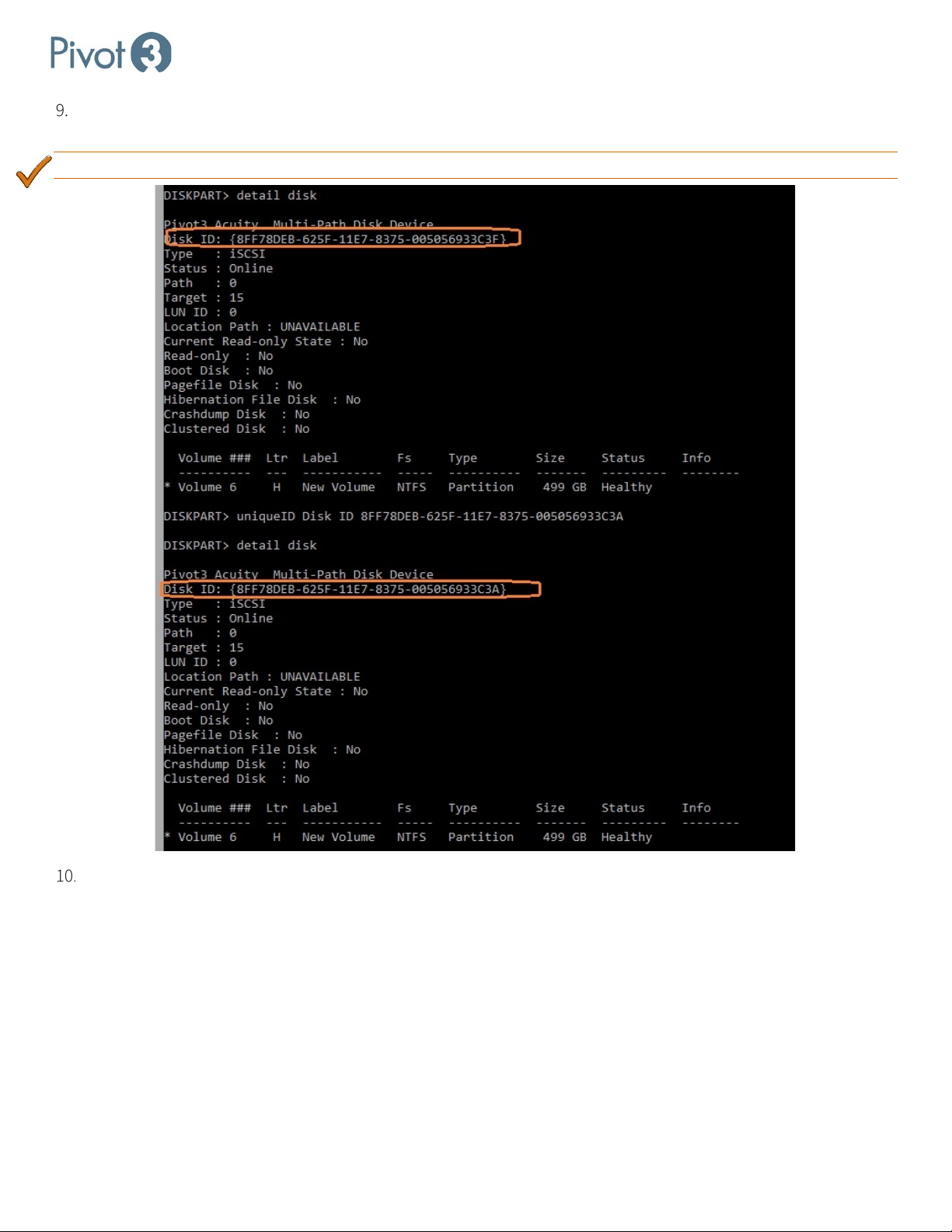
Setup & User Guide
Change the disk ID to ensure a unique disk ID for the new clone. Run detail on the disk to ensure the ID has been
changed successfully.
BEST PRACTICE:
If this is not done, duplicate disk IDs will exist in the partition and can cause issues with Windows.
The volume can now be accessed for data recovery.
3rd Party Backup Applications
Snapshots should not be a replacement for a disaster recovery strategy; administrators should always have access to a
rd
full backup. Pivot3 Acuity Software Platform supports 3
provider, and can interact with applications such as:
• Veeam
• Backup Exec
• CommVault
• NetBackup
| 96
DOC-246-GDE-Pivot3 Acuity 2.3 Setup & User Guide-v1.0.docx
party backup applications interfacing with ESX and the VSS
Page 97

Setup & User Guide
Section 13 Replication
Asynchronous Replication Overview
Asynchronous replication creates a copy of a source volume on a target Acuity vPG. When a snapshot is taken of a source
volume, the source data is copied to an inbound replication volume on the target vPG. Only data that has changed from
the previous snapshot is sent, so replication is faster and impact on system performance is minimized.
Asynchronous replication allows multiple source volumes on a vPG to be replicated in parallel, up to four source jobs per
accelerated node for a total of eight jobs per vPG. When multiple simultaneous jobs are started, they run in parallel on the
two accelerated nodes of the source vPG. Replication will automatically select the pool with the most available space to
host the inbound replication target. If there are multiple jobs with the same performance policy, they run in the order that
the snapshots were taken. The snapshots inherit a performance policy one less than the source volumes being copied.
It’s important to remember that while there is a limit of eight asynchronous replication jobs that run in parallel on a
source vPG, a target vPG may be the target for any number of asynchronous replication jobs – and the target system is
limited to, at most, 20 simultaneous replications. Schedule asynchronous replication jobs carefully to avoid reaching this
limit or saturating the links. Throughput and time spent replicating are optimized by sequencing a few jobs at a time and
not scheduling them to kick off all at the same time.
To verify that the scheduling of replication jobs is optimized to produce minimal system impact, monitor the Long
Running Tasks list. If needed, immediate corrections can be made by canceling tasks. If replication tasks are continuously
being superseded, this is an indication that the replication interval is set too low and should be increased. The longerterm solution is to change the replication schedules to minimize accumulated jobs.
Snapshots can be retained or deleted based on a schedule or policy. If the retention is set to 10, replicated snapshots will
th
accumulate until there are 10 successful replications on the target; when the 11
deleted from both the source and the target vPGs.
The retention count for a protection policy or schedule only applies to that protection policy or schedule. For example, if a
volume has retention set as follows:
• Daily schedule with retention count of 7
• Weekly schedule with retention count of 4
• Monthly schedule with retention count of 12
The retention for each unique schedule or protection policy is tracked separately, so that for the above volume the
volume would have 7 + 4 + 12 = 23 replication snapshots.
Retention on a schedule does not apply to manual snapshots. If a snapshot is taken manually, it must be deleted
NOTE:
manually. Manual snapshots are not included in the retention count.
The size of the snapshot on the source may be different from the size on the target. This is normal and expected behavior.
There are a variety of factors that can cause this to happen: partially filled write blocks, data reduction on the target,
snapshot frequency on the source being different from replication frequency to the target, for example. More information
on this issue is provided in Acuity Data Usage Reporting.
replica is completed, the oldest is
Replication jobs are prioritized by the QoS level of the source volume. If multiple replication jobs are queued, MissionCritical jobs will be run before Business-Critical jobs, which are run before Non-Critical jobs. However, if lower priority jobs
are skipped, their priority is gradually boosted so that they will eventually run and not be queued indefinitely.
97 |
DOC-246-GDE-Pivot3 Acuity 2.3 Setup & User Guide-v1.0.docx
Page 98
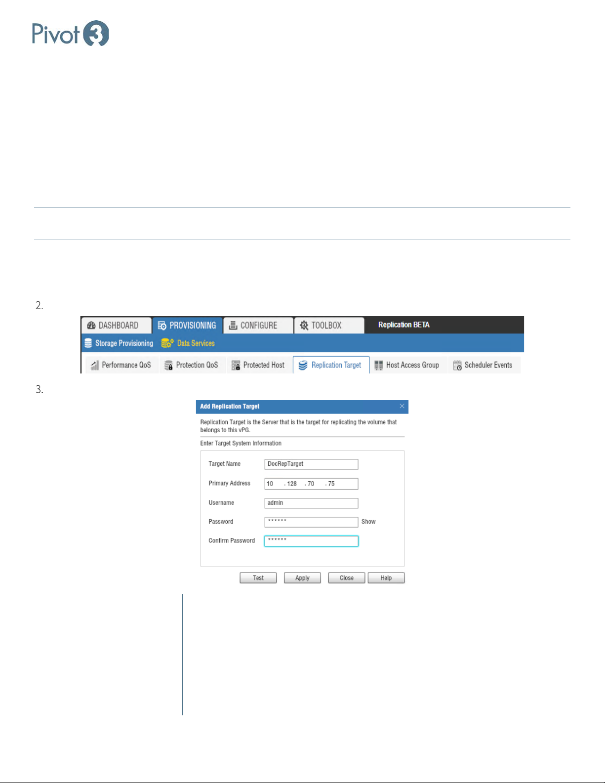
Setup & User Guide
A replication job will run at the QoS level of its source volume minus one level. This will prioritize I/O to a volume above
the replication activity for that volume.
Replication will fail if the source or target systems become non-Active-Active (caused by failure or explicit activity such as
Maintenance Mode). If the replication job was scheduled, then the next time that schedule fires, the replication will be retried. If the source and target systems are now Active-Active, then the replication will proceed.
Configuring Replication Target IPs
A replication target is another Acuity vPG to which replicas of local volumes can be written. Targets must be configured
before volumes can be configured for replication.
Both Management and SAN NICs support replication tasks. Whichever network is initially specified will be used by
NOTE:
Acuity; replication will not run across different networks unless routing is specifically set up.
To configure replication targets, navigate to the Provisioning tab > Data Services view > Replication Target tab. Select
the desired vPG from the drop-down menu in the top right of the window.
Adding a Replication Target
Choose Add Replication Target from the tab menu options.
Fill out the fields as shown in the pop-up dialog.
Target Name Enter a descriptive name for the target.
Primary Address Enter an IP address for the target accelerated node; the address of
any port – data or management -- can be used on the target node.
Username Enter the username for the target vPG.
Password Enter the password for the target vPG.
Confirm Password Re-enter the password for the target vPG.
| 98
DOC-246-GDE-Pivot3 Acuity 2.3 Setup & User Guide-v1.0.docx
Page 99
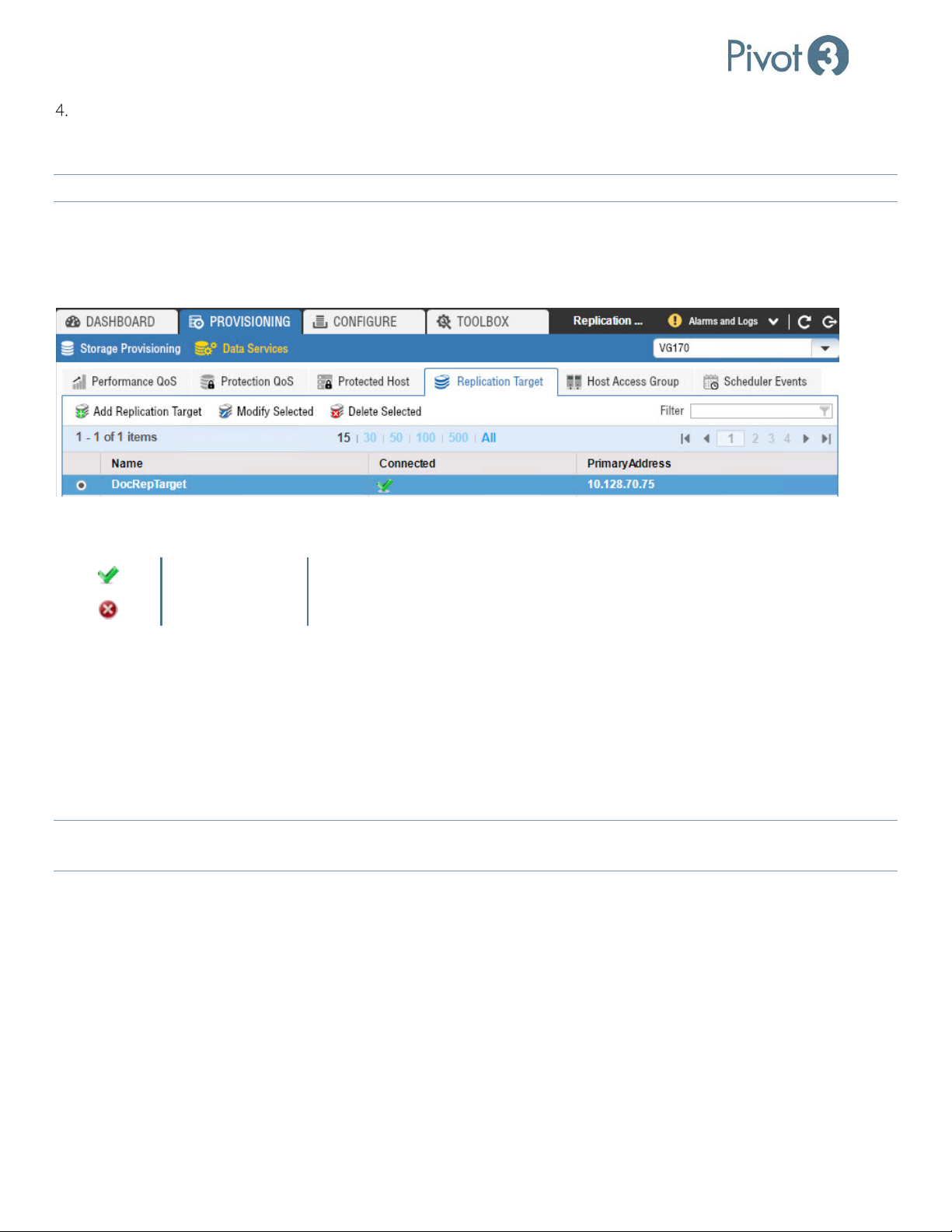
Setup & User Guide
Optionally, select the Test button to verify that the target system is accessible and that the username and password
are correct; if the test fails, confirm and re-enter the field values. Once all fields are filled out and accepted, click
Apply.
The target and originating nodes must be on the same subnet, unless the subnets allow routing.
NOTE:
Managing Replication Targets
Once a replication target has been successfully created, it can be accessed from the Provisioning tab > Data Services
view > Replication Target tab.
The Connected column provides a quick view of the connection status for that replication target. The following status
icons are possible:
Green Check Successful connection with replication peer
Red X Replication target is not accessible
Modify Selected
Choose Modify Selected from the Replications Target tab. Change the values as necessary. Optionally, press Test to test
the connection using the new values. Press Apply to save changes or Close to dismiss the pop-up with saving any
modifications.
Delete Selected
Choose Delete Selected from the Replications Target tab. Press Delete to confirm the deletion or Cancel to dismiss the
pop-up without deleting the replication target.
If there is an attempt to delete a replication target that is in use in schedules or policies, the delete will fail and identify
NOTE:
a schedule that uses the replication target.
99 |
DOC-246-GDE-Pivot3 Acuity 2.3 Setup & User Guide-v1.0.docx
Page 100
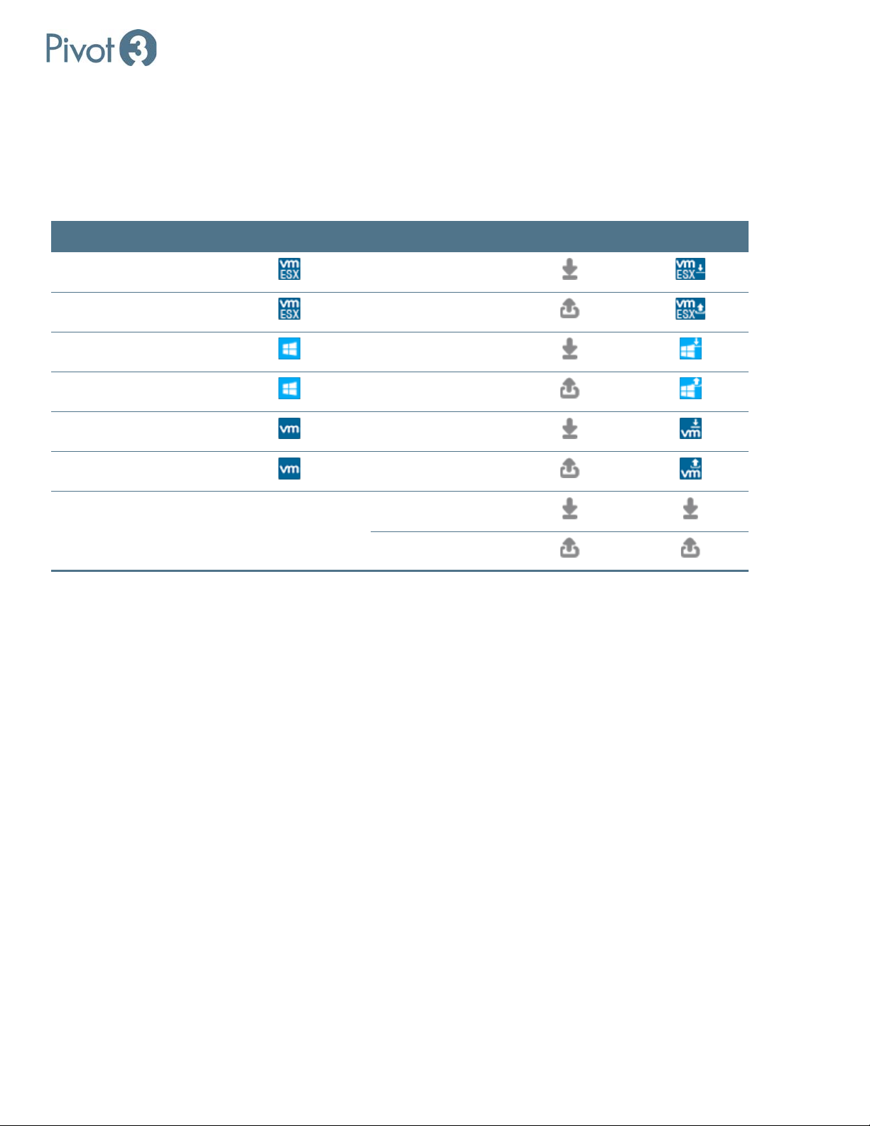
Setup & User Guide
Replication Icons Associated with Volumes
When configuring replication, it is critical to configure servers as Protected Hosts. Protected Hosts are ESXi Servers and
Windows Servers hosting volumes on the Acuity platform, allowing customers to create snapshots that are properly
quiesced from the perspective of the operating system and applications running on Acuity volumes.
For more information about configuring Protected Hosts, consult sub-section Protected Hosts.
Managed Volume Managed Volume Icon Replication Type Replication Icon Combined Icon
VM ESXi
VM ESXi
Windows
Windows
VM
VM
Inbound / Target
Outbound / Source
Inbound / Target
Outbound / Source
Inbound / Target
Outbound / Source
Non-Managed Volume No Icon Inbound / Target
Outbound / Source
| 100
DOC-246-GDE-Pivot3 Acuity 2.3 Setup & User Guide-v1.0.docx
 Loading...