

Page 1
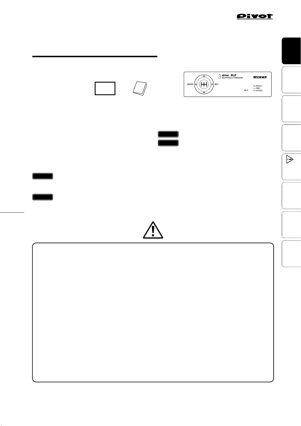
(BLP As of November, 2016 No.7)
Produc t Number :
()
USER’S MANUAL
Thank you for purchasing PIVOT product.
Please read this manual carefully and keep it for future
reference.
If this product is given to another
user, make sure to include this
User’s Manual.
Product
BLP
+
Contents
Before Using …………………………………………………… 1
Product Features …………………………………………… 2–3
Features……………………………………………………… 2
Contents …………………………………………………… 2
Part Names / Display Items ……………………………… 3
WARNING / CAUTION ……………………………………… 3
procedure 1
Connecting The Wires ……………………… 4–6
Clutch Signal………………………………………………… 4
Brake Switch / Earth / Car Speed Signal …………… 5–6
procedure 2
Installing The Product ………………………… 6
Throttle Controller with Built-in MT Auto-Blipping Function
drive・BLP
BLIPPING & THROCON
3
procedure 3
Initial Settings (Degree of Acceleration Setting)…… 7
procedure 4
Speed Pulse Settings…………………………… 8
How to Operate………………………………………………8–10
Operating the Auto-Blipping …………………………… 8–9
Auto-Blipping Test…………………………………………… 9
Operating The Throttle Controller ………………………… 10
Basic Operation ……………………………………………… 11
Troubleshooting ………………………………………… 11–12
Before
Using
Features
Connecting
The Wires
The Product
Installing
Settings
Initial
Speed Pulse
Settings
After installation, make sure to carry out “Initial Settings”.
After having installed this product, make sure to make settings for your car’s special characteristics by
carrying out the “Initial Settings” on Page 7. If the “Initial Settings” are not carried out, a Check Engine
Light may go on. Also, the unit will remain in NORMAL Mode even if the Mode is switched.
Worried about Installation?
If you are worried about carrying out wiring or other installation procedures please consult your dealer.
Only use 3-drive Specialized Harness.
Using another type of harness will cause troubles and failure; use only the 3-drive specialized harness.
Set to NORMAL Mode upon Removal of Product.
When uninstalling the product, make sure to return it to
Reconnecting this product in a different mode may cause the Check Engine Light to come on.
Modifying this Product is Forbidden.
Under no circumstances should modifications or changes be made to this product. Doing so may cause damage
not only to the product, but to the car and the operation of the car in which it is installed.
(NORMAL) Mode before carrying out any work.
nor
Operate
How to
Shooting
Trouble-
1
Page 2
Features
[With Auto-Blipping]
[Without Auto-Blipping]
Slip
RPM
RPM
G
G
Thrott le
Openin g
27%
Thrott le
Openin g
50%
Thrott le
Openin g
89%
Throttle Controller with Built-in MT Auto-Blipping Function
Using
Before
BLIPPING
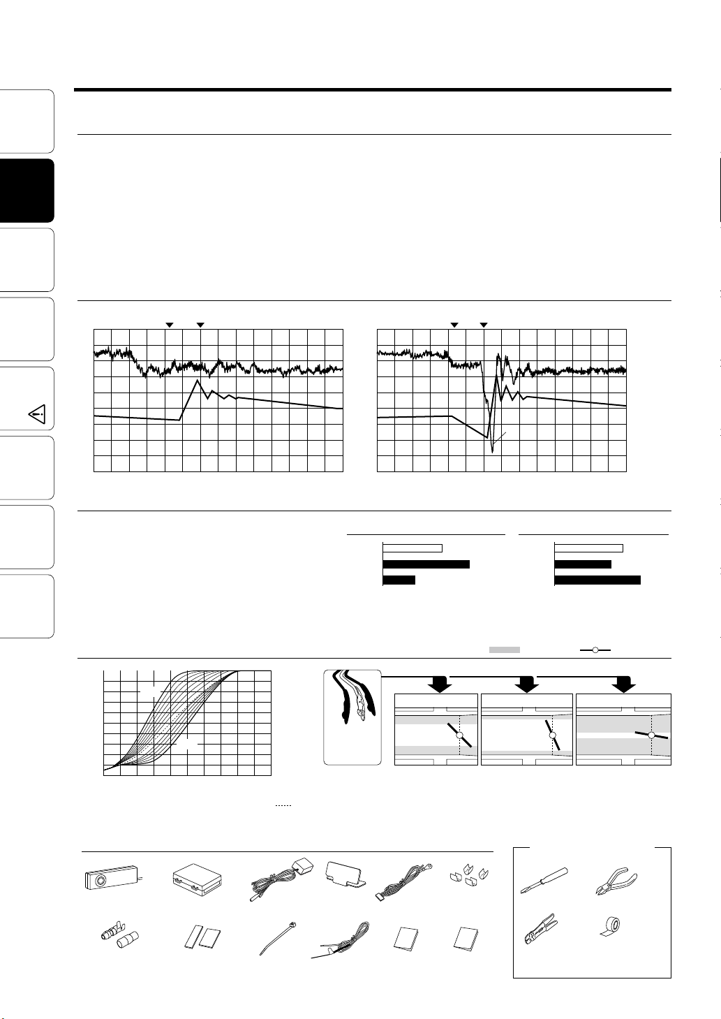
Auto- Blipping Auto- Blipping removes the need for the conven-
tional “ heel and toe” technique used to raise rpm with the accelerator
while braking at the same time in an attempt to prevent slip ping and
turbulent motion caused by rapid downshifts when sports driving in
Features
manual transmission model cars. This allows the driver to concentrate more on braking whic h in turn re sults in a more acc urate and
smoother deceleration. Operation is safe as the Auto-Blipping function does not operate when accelerating without braking or when a
set spee d has not been reached. (Patent pending)
The Wires
Connecting
Installing
Initial
Speed Pulse
Comparison of Deceleration G’s at Downshift (from 3rd-2nd)
Release
Depress
Clutch
(G)
0.2
0
The Product
-0.2
Settings
-0.4
-0.6
Settings
G
RPM
RPM RPM
Clutch
[With Auto-Blipping]
[With Auto-Blipping] [Without Auto-Blipping]
10 234567 10 234567
Time (sec) Time (sec)
Adjust to M ost Suitable B lipping When using blipping to raise the
engine’s rpms, it is possible to fine tune the settings for deg ree of
acceleration, time length of operation and the s peed at which
blippi ng star ts; making the perfect match for your car mod el and
driving conditions.
Easy Operation After starting the engine, si mply press the AutoBlipping switch to ON and Auto-Blipping will engage after having
reached the set speed when the clu tch is de pressed while s tepping
on the brake
Release
Depress
Clutch
(rpm)
100 00
8000
6000
4000
2000
G
RPM
Clutch
Slip
Slip
[Without Auto-Blipping]
How to
Operate
Trouble-
Shooting
2
THROTTLE CONTROLLER
Throttle Controller for Best Response to Match Driving Style and Conditions
The controller has three modes to match your dr iving
style and conditions whether driving for sport, driving
slippery roads or driving with gas efficiency in min d:
NORMAL M ode for regular response, SPORTS Mode
with 7 steps for a quicker response, an d ECO Mode with
3 steps for a slower response. The choice is yours.
Comparison of Fuel Consumption
NORMAL
SP7
SP7: MAX. SP ORTS Mod e / Ec5: MAX . ECO Mode
HONDA STEP WGN (R G1) / Running dist ance: 0 –40 0 m
Degree of a ccele ration: 3 0%
Examples of Changes in Throttle Opening
100
Throttle Opening (%)
50
0
SP 7: MAX. SP ORTS Mode Ec 5: MAX. EC O Mode
SUZUKI Swift (ZC31S)
SP7
Ec5
50 100
Degree of Acceleration (%)
NORMAL
Degree of
Acceleratio n
e.g. 40%
Please check the contents of the package
Controller
[78× 22×14 (D)mm]
Male Connector
with Covers
× 2
50× 22× 70(D) mm]
[
Double-sided Tapes
Unit
[45×14mm] ×2
[25×35mm] × 2
Clutch
Adapter
Zip Ties
(Large) × 2
(Small) × 2
L-shaped
Fastener
Voltage
Detector
Comparison of Acceleration Time
Throttle
Throttle
Opening
Opening
27%
27%
NORMAL
SP7
Ec5
Air Intake
SPORT S Mode (S P7)ECO Mod e (Ec5)
Throttle
Throttle
Opening
Opening
89%
89%
107cc
157 cc
Ec5
58cc
NORMAL Mode
Throttle
Throttle
Opening
Opening
50%
50%
Note: In som e car mod els wit h a Valvematic engine, control is carried
out by the intake valve r ather th an the throttl e valve.
Tools and Materials to
prepare for Installation
Powe r
Cable
User’ s Manual
(This Book)
Cut
Connectors
×4
Wiring Chart
(in Japanese)
Screwdriver
Crimpers
Sec
23
Sec
19
29
Throttle Valve
Nippers
Insulating
Tapes
and others
Sec
Page 3
Part Names
Before
Using
1
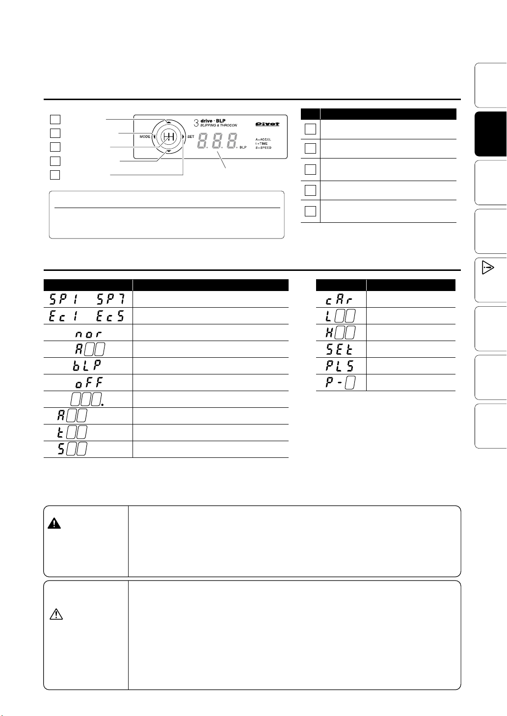
UP Switch
2
MODE Switch
3
BLP Switch
4
DOWN Switch
5
SET Switch
Display
Turning off the Display
This product is interlo cked with the ECU (engine computer) power. Depending on the m odel of c ar, the disp lay may remain on for up to 15 minutes
even after the ignition has been turned to the OFF position; this i s normal.
Display Items
Display Details
–
–
SPORTS Mo de (Hig her number = Higher resp onse)
ECO Mode (H igher n umber = Lo wer resp onse)
NORMAL (Normal Performance)
Degree of Acceleration
Auto- Blipp ing Mod e: ON (On set ting)
Auto- Blipp ing Mod e: OFF (On set ting)
No. Function
Switch t o Raise Settin gs
1
Switch b etwee n Throt tle Con troller Modes
2
Switch t o turn ON / OFF
3
the Auto -Bli pping functi on
Switch t o Lower Set tings
4
Switch t o adjust the Auto -Blipping settin gs
5
Display Details
Initia l Setti ngs Mode
Position when accelerator is
not pres sed down.
Position when accelerator is
fully pressed d own.
Setti ngs Com pleted
Speed Pu lse Set ting Mo de
Speed Pulse Number
Features
Connecting
The Wires
The Product
Installing
Settings
Initial
Speed Pulse
Settings
Operate
How to
(
blinking
A
(
blinking
t
(
blinking
S
WARNING
Improper use or disregard
of these warnings may result in the injury or death
of people.
CAUTION
Improper use or disregard
of these warnings may
cause injury to persons,
damage the product and/or
other things.
Auto-Blipping Mode: ON (In operation)
Degree o f Accel eratio n of Auto-Blip ping
)
Time len gth of op eratio n of Auto -Blip ping
)
Minimum Speed of Auto-Blipping start
)
• When making ini tial set ting s make
sure to sto p the eng ine and p lace in
Neutra l. It is dan gerou s to carr y out
these se ttings while t he engi ne is
running.
• Do not work in area s where th ere is
excessi ve exhaust. Due to vehicle
exhaust e missi on pois oning o r fire
may resul t in a damage to humans.
• PIVOT Corporatio n accepts no responsibility, in any manner whatsoever, for damag e and/or troubl e to
your vehic le or pro duct, nor for any
accid ents that are the re sult of the
misuse o f this product .
• Please c onfirm that the t ype of veh icle you wish to install into is listed in
the “li st of Spe cialized Harnesses
by Car Mod el for 3- drive・BLP” .
•When installing this product, we
recom mend that if tech nical k nowledge becomes necessary please
consult a quali fied me chani c.
•Do not crush the cable. Please be
careful that the cable does not get
crushed by the se at rail or c ar door
steel plate, nor cut by any sharp
steel pl ate as this may cause a p oor
conne ction o r an elec tric sh ort
leadin g to fire or ot her dan ger.
• If the device is improperly ins talle d
or settings have been improperly
made a Che ck Engi ne Light m ay go
on.
• Do not us e electrotap.
•Wiring should be carried out using
the att ached “ cut con necto r” or by
soldering, make sure to securely insulate all wiring parts with insulation
tape, and confir m that no wires are
sticking out.
• While driving D O NOT oper ate
switches or pay prolonged attention
to the dis play; it is extrem ely dan gerous.
• Make sure that all w iring and fastening d own of the p roduc t does not
interfere with d rivin g nor be do ne in
such a way as t o cause poor con nections.
• Please wipe wit h a soft dry clo th (a
lens cloth).
• Please do not use a lcohol or benzine. Thi s may caus e damage to the
painted surface or cracks in the
plastic.
•Do not, in any manner, process,
take apar t, or make c hange s to this
product.
Shooting
Trouble-
3
Page 4
procedure 1
Connecting The Wires
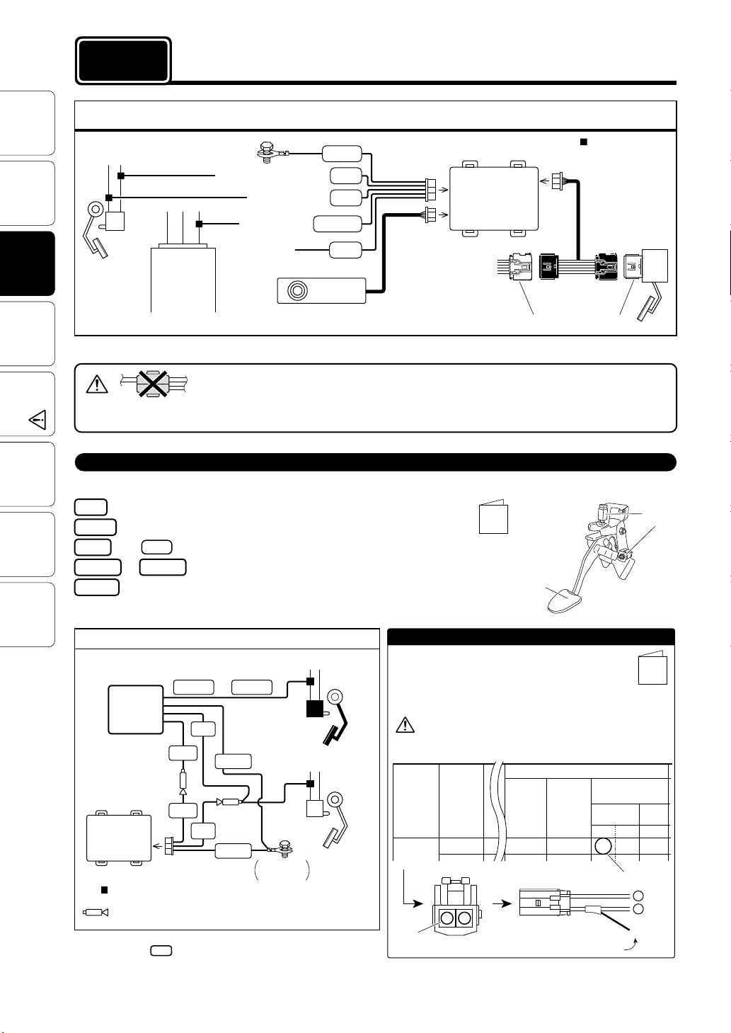
Basic Wiring
Using
Before
(1.5m)
(1.5m)
Features
The Wires
Connecting
Note 1: After inserting the connector, pull lightly to make sure that it is securely locked.
Installing
The Product
Brake
Brake
Switch
Connector
ECU, etc...
When installing make sure to use the correct Specialized Harness for your car model.
(1.5m)
(1.5m)
Controller
Black
Red
Gray
Orange
Pink
Option
Earth
Brake Power (normal 12V)
Brake Switch Signal
(1.5m)
Car Speed Signal
SP
Clutch Signal
(⇒See the bottom of this page)
• When connecting to the car side wires, do not only use “electrotap” as this may result in a poor
electrical connection. Please use the supplied “cut connectors” or solder the wires together and
Settings
Initial
• The Brake Switch Connectors will differ depending upon the car model, grade and year, so please sure to check the design in the “Wiring Chart”.
• Remove the battery cables from the minus terminals before carrying out the wiring.
make sure to use insulation tape to securely insulate the wire connection.
Clutch Signal (Use included Clutch Adapter)
Connecting the Clutch Adapter
Settings
Speed Pulse
Red
Black
How to
Operate
Brown Purple
Green
Trouble-
Shooting
Pink
To Brake Power (normal 12V)
To E art h
To Pink code of 8-pin Connector
or
Spare wiring (usually not used)
Basic Wiring
Brown Purple
Clutch
Adapter
To Clutch Signal
or
Red
Pink
Black
Pink
Unit
: Use Cut Co nnect or
(Refer to pag e 6 [Referen ce 2] “Ho w to use the Cu t Conne ctors” )
: Use Male C onnector
(Refer to pag e 6 [Referen ce 3] “How t o use the Ma le Conn ectors ” )
Note: For some car models like 86/BRZ with push button star t system,
con nec t d ire ctly code from 8-pin Connector of the unit side to
Clutch Switch Signal without using Clutch Adapter.
Red
8-pin Connector
Pink
Black
Fastene d two
terminals
• Connect the wires of Clutch switch
signal to the corresponding wires
found in the “Wiring Char t”.
• The car which has 2 clutch switch connectors, choose one which works with depressing the clutch pedal.
• Cut off t he insul ation of the tip of the cod es,
among of Brown and Purple and Green
code which you need to connect, then
bundle the extra code.
(Clutch Switch Signal)
Clutch
Switch
(Brake Power)
Brake
Switch
Earth
Clutch
Brake
: Use Cut Connector
8-pin Connector
(See Note 1)
5-pin
Connector
(See Note 1)
(1.5m)
Unit
Wiring
Chart
6-pin Connector
(See Note 1)
(0.5m)
Special Model
Specific Harness
(sold separately)
Accelerator Connector
Clutch
Pedal
How to Connect
1.Check the wiring of Clutch Switch Signal ,necessity of
Clutch Adapter and the corresponding wire colors in
the included " Wiring Chart ".
2. Connect the wires using included Cut connectors.
(Refer to page 6 [Reference 2] “How to use the Cut Connectors” )
Note that the colors listed in the chart under “Clutch
Adapte r Wire Co lor” are not the colors of the wir es on
the car side.
e.g. TOYOTA Vitz (from Feb. 2005)
クラッチ関 係
メーカー
TOYOTA
Brown
車名
ヴィッツ
ア
(MTC-7)
クラッチ
スイッチ
コネクター
H17.
イ
クラッチ
アダプター
○: 使 用 す る
形状
×: 使 用 し な い
MTC-7
Switch Connector
Wire leading
from Clutch Adapter
○
クラッチアダプター
のコード色
茶紫
ア
Accelerator
接続記号
Connection
letter
イ
ア
Brown
Clutch
Switch
Wiring
Chart
ユニットの
コード色
ピンク
4
Page 5
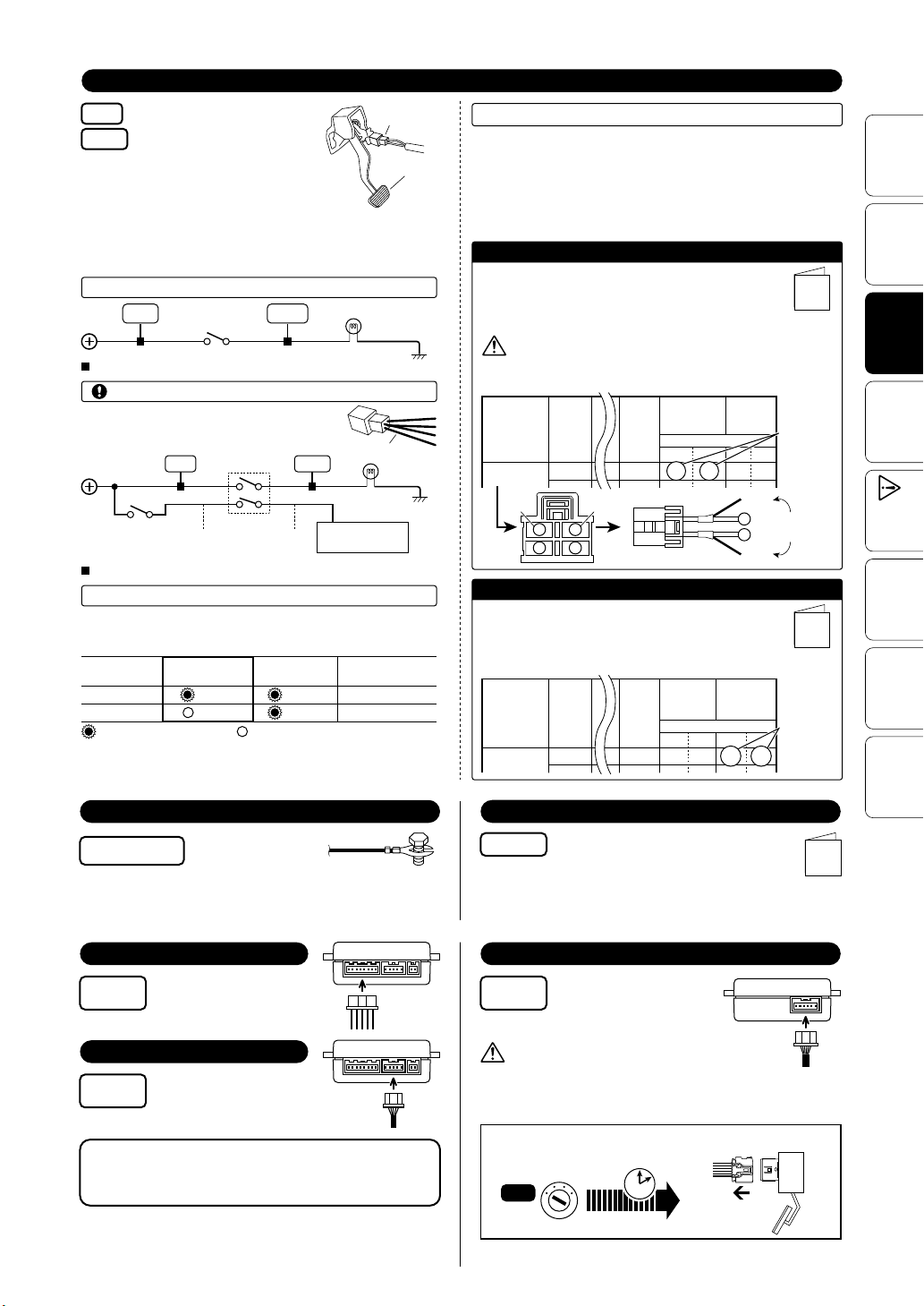
Brake Switch (Brake Power and Brake Switch Signal)
Accelerator
To Brake Power (normal 12V)
Red
Gray
To Brake Switch Signal
• There may be two or four(or more) wires
coming from the brake switch connector. Check the wiring position in the
“Wiring Chart” and after te sting the
voltage, carr y out the wiring.
• After having completed the wiring confirm that the brake lamp
is working properly.
For a Two-Wire Connector
Brake
Switch
Press Down
on Brake Pedal
Gray
(See below
Gray
(12V)
(12V)
Red
: Use Cut Connector
For a Four(or more)-Wire Connector
When there are four(or more) wires, do not wire
to positions A and B as shown below.
for how to check the voltage for each wiring position)
Ignition Switch
(12V with ignition
in the ON position)
: Use Cut Connector
How to Test
1. Turn the ignition to the OFF. Please put gear into N (Neutra l).
2. Check the terminal for each of the connec tions a s desig nated in
the separate sheet “Wir ing Char t” .
The Wire color
of the product
Red
Gray
: Voltage Tester Lamp ON : OFF
Note: If t here are four(or more) wires, do not wire the rema ining
(OFF 0V)
Brake
Switch
Red
AB
(Refer to page 6, [How to use the Voltage Detector].)
Not Press Down
on Brake Pedal
(12V)
(0V)
.
Brake Switch
Connector
Brake
Lamp
Four Wires
Brake
Lamp
IGN
Operation Signal
Brake Power
Brake Switch Signal
Brake
Pedal
Earth
Earth
Select a Wiring Method
Select from either “Connect Directly” or “Connect using
Brake Harness” and carry out directions as stated.
1. After having tested voltage at the positions to be wired, connect as
directed.
2. In case of the car model which is blank of Wire Number s or Brake
Harnes s Conne ction Color of “ Wiring Char t” , please make sure to
carry out a voltage test and connect as dire cted.
Connect Directly
Connect the Red and Gray wires to the corresponding
wire numbers found in the “Wiring Chart” using Cut
connector whi ch is included.
(Refer to page 6 [Reference 2] “How to use the Cut Connectors” )
Note th at the co lors lis ted in the char t under “Brake
Harne ss Conn ection Color” are no t the colors of th e wires
on the ca r side.
e.g. TOYOTA 86 (from Apr. 2012)
TOYOTA
車名 年式
86
Gray Red
132
(BR-7)
直接接続
ブレーキ
接続番号
ハーネス
品番
H
24.4
〜
4
赤灰赤灰
BR-7
2
Switch Connector
製品のコード色
1
ブレーキ
ハーネス
接続色
黄青
Red
2
Wire leading
from product
1
Gray
Connect Using Brake Harness (sold separately)
Connect the
colors found in the “Wiring Chart” .
(For more details , please refer to the brake harness manual.)
e.g.) TOYOTA 86 (from Apr. 2012)
TOYOTA
86
Red and Gray
車名 年式
H
24.4
wires to the corresponding wire
直接接続
ブレーキ
接続番号
ハーネス
品番
〜
赤灰赤灰
BR-7
2
ブレーキ
ハーネス
接続色
製品のコード色
1
黄青
Wiring
Chart
Connection
Numbers
Wiring
Chart
Connection
Colors
Before
Using
Features
Connecting
The Wires
The Product
Installing
Settings
Initial
Speed Pulse
Settings
Operate
How to
Shooting
Trouble-
Earth
with earth
Black
terminal
Note: Painted screws and screws connected to plastic parts are
not earthed; make sure to connect only to a place which i s
earthed.
Fasten to a screw of a
metal part which is
earthed.
Power Cable
8-pin
Connector
Connect to the side of
the unit.
Controller
5-pin
Connector
Connect to the side of
the unit.
After inserting the connector, pull lightly to
make sure that it is securely locked.
Car Speed Signal
Orange
Note: Connect only to the cables on the car side as directed.
(Do not wire the speed signa l to the CAN-BUS adaptor.)
Confirm the positions on the “ Wiring
Chart” and then connect.
(⇒Refer to page 6 [Reference 2] “How to use the Cut
Connectors” )
Wiring
Chart
Special Model Specific Harness (sold separately)
6-pin
Connector
Depending on the type of vehicle, if the connector is disconnected before the
ECU power is switched OFF the Check Engine Light may go on. (If the Light
comes on: Refer to page 12, “How to Turn Off the Check Engine Light” )
Turn the ignition
Note: For details ab out connect ing the Specia lized Har ness, p lease r efer
to the user’ s manual t hat came w ith that harnes s.
Connect to the side of
the unit.
Only disconnect the ac celerator connector after
having waited at least 15 minutes from the time
that the ignition was turned to th e OFF position.
Accelerator
Connector
Disconnect
the connector
to the OFF
position.
OFF
Passage of over
minutes
15
Accelerator
Accelerator
5
Page 6
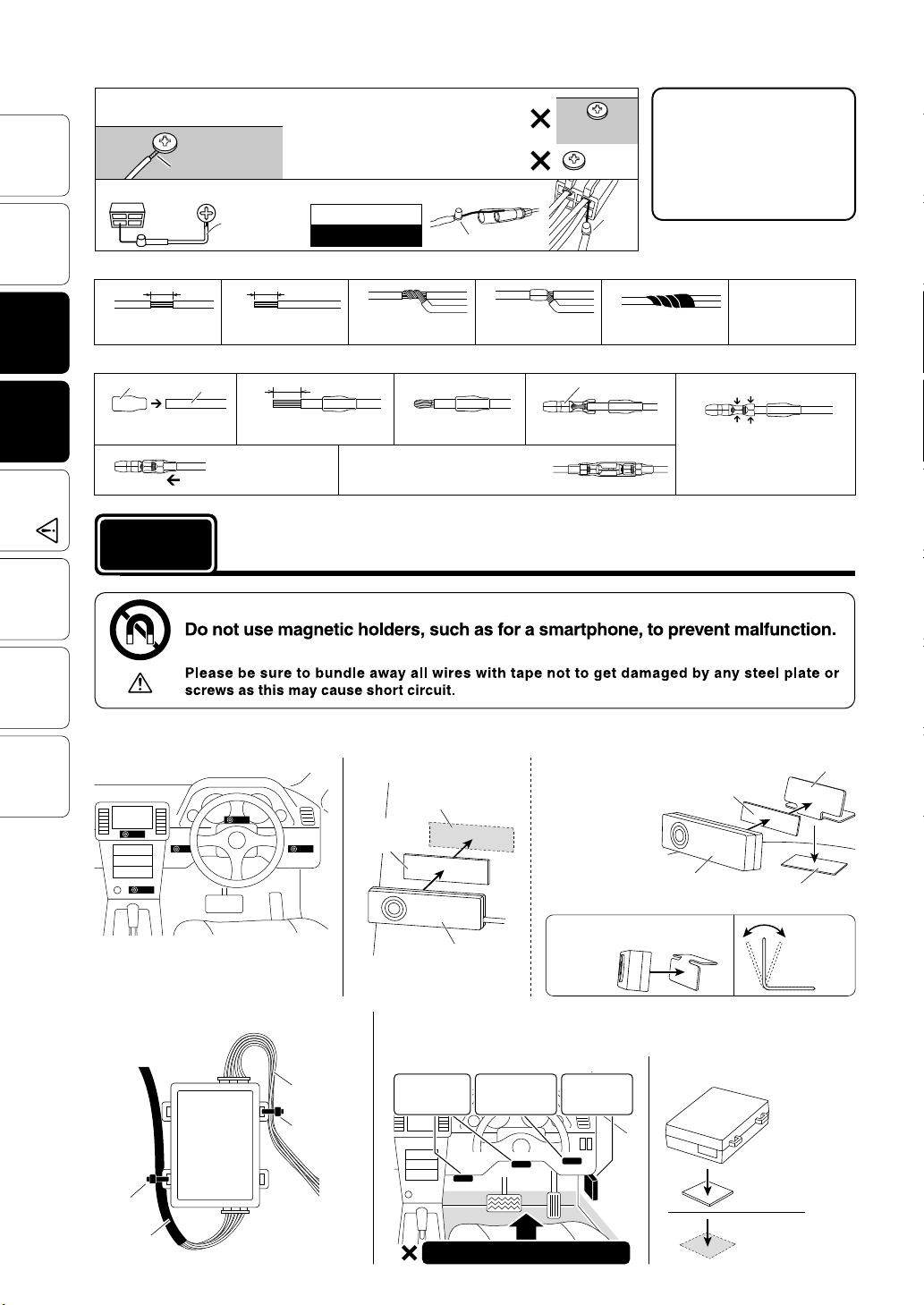
[Reference 1] How to use the Voltage Detector (supplied with product)
Metal part
Wire tip
Plastic part
(Examp le of Ins tallation)
Fasten t he c ab les not to d iscon nect c onnec tor s
by getti ng caught on cables.
Loosen an earthed screw, insert
1
and fasten the wire tip (coiled wire).
Metal part
Metal part
Wire tip
Wire tip
(Screw,
10 mm
Male sleeve
Earth
etc...)
Voltage Detector
(supplied
with product)
2
Peel off of the vinyl
cover at the end of the
product’s wire.
Wire
Using
Before
Connect the tip of the LED to the place you wish to test voltage.
2
Features
[Reference 2] How to use the Cut Connectors
1
Peel off of the vinyl
cover at connection.
The Wires
[Reference 3] How to use the Male Connectors
Connecting
12
Note: As an earthing screw, on ly use a
screw th at is faste ned to a metal par t.
Painted screws and screws connec ted to
plasti c part s become insul ated and c annot
carry electricity.
Lamp on : 12V
Lamp off : 0V
10 mm
10 mm
34
Wrap around both
wire coils.
In some car models, voltage
Plastic part
Plastic part
Painted
screw
detector which is supplied
with product doesn't work
because of the current
capacity shortage. Please
use analog multimeter and
others in this case.
LED
LED lamp
Close tightly with cut
connector.
3
4
lamp
5
Insulate with vinyl
tape.
Male Connector
When crimping, please
use crim pers or u se
pliers to bend and then
solder together.
5
Crimp th ese plac es
Pull the cable through the
The Product
Settings
male sleeve.
6
Installing
Initial
procedure 2
Settings
Speed Pulse
How to
Operate
Installing The Controller
(Example of Installation)
Trouble-
Shooting
Remove about 10 mm of the
cable casing.
Affix the male sleeve to
the places as mentioned
above.
Note: Afte r conne cting th e male an d female
connectors, make sure to firmly twist the
male sleeve inside the female sleeve.
Turn back the ti p of the
wires.
Installing The Product
Install the Controller to a position which is easy to see.
Fastening to a Flat Place
Clean to remove
oil and dust.
Double-sided
tape (Included)
Controller
Connect the male connector
to the end of t he cabl e.
Using the L-shaped Fastener
By using the
L-shaped Fastener
that comes with
this product, it is
possible to install
the unit on the
dashboard even if
it is curved or on
an angle.
Note: It is possible to install the
L-shaped Fastener in the reverse
direction.
Controller
Crimp do wn with cr impers t o make sure
that the inner wires are firmly connected to the in ner part o f the con nector
and that th e cable s ectio n is conn ected
to the oute r part of t he conne ctor.
L-shaped Fastener
Double-sided tape
(Included)
Double-sided tape
(Included)
Adjustable
angle for
easier
viewing
Cable processing of the Unit Installing The Unit
Fasten the cables not to disconnect connectors
by getti ng caught on cables.
Power Cable
Zip Tie
(Small)
Zip Tie
(Small)
Specialized
Harness
To P ow er
Sorce
Label
To S pe cia lize d
Harness
As shown in the diagram below, fasten the unit into positions not usually af fected by water.
(Examp le of Ins tallation)
Under the
steering
column cover
6
On the
back side of
the und er cover
On the
inside of the
kick panel
Do not install into low positions
Fastening to a Flat Place
Unit
Double-sided
Tape (Square)
Clean
to remove
oil and du st.
Page 7
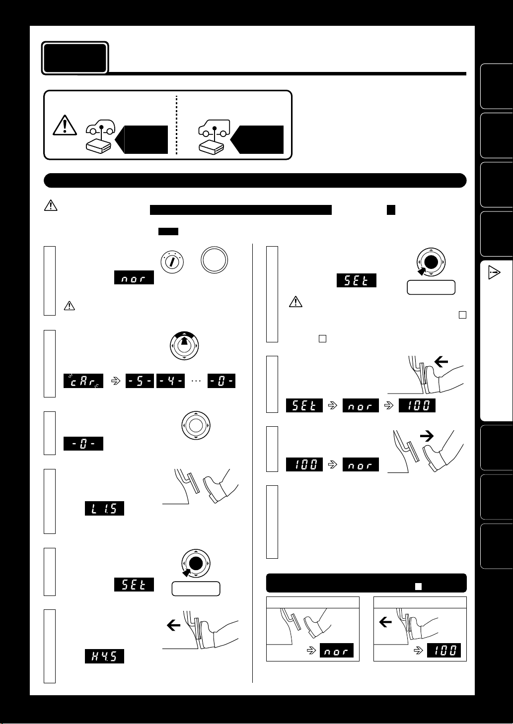
procedure 3
Initial Settings (Degree of Acceleration Setting)
Make sure to carry out these settings.
Before
Using
When installing for
the first time
Initial
Settings
When installing into a
different car
Initial
Settings
Before making the “Initial Settings”
1. Make settings only after having completed all wiring (connector installation).
2. Make settings with the
[Making the Settings]
Turn the ignition ON.
1
(Engine not running)
•
will
nor
appear.
If
nor
Press the UP switch for
2
10 seconds or longer to
change the display to 0 .
(Count down from 5 to 0 after the
(NORMAL Mode)
does not appear, press the MODE switch until
nor
appears.
ignition in the ON position (engine not running) and the gear in N (Neutral).
: Controller Display Area, ( ) contains additional explanation
ON
START
or
Without press the
clutch pedal,
press down twice
Press until
“0” appears
ENGINE
STOP
With the accelerator at 100%,
7
press the BLP switch.
•
SEt
appear.
If after the
(
L1.5
settings have not been confirmed properly. Re-do the settings
from step 4 .
Press down on the accel-
8
erator pedal until
appears.
blink.)
cAr
• This operation sets the car’s accelerator
characteristics into the controller unit.
• If the “Initial Settings” are not carried out,
the unit will remain in NORMAL Mode even
if the Mode is switched.
• If this settings have been improperly made
a Check Engine Light may go on.
Press
will
Set to 100%
If
is displayed
Err
is shown the display returns to as shown in 4
Err
or so on), it means that the degree of acceleration
100
Features
Connecting
The Wires
The Product
Installing
Initial
Settings
Make sure to carry out
this operation.
SEt
0
will
appears release
0%
Set to 0%
100%
When
3
the UP switch.
Accelerator pedal is not
4
pressed down.
(Release the accelerator to 0%)
(e.g.)
(Voltage Display: e.g., 1.5V. The values shown in the display will
vary depending on the type of car.)
With the accelerator at
5
0%, press the BLP switch.
•
appear.
Pedal is completely
6
pressed down.
(Press in on the accelerator to
100%)
(e.g.)
(Voltage Display: e.g., 4.5V. The values shown in the display will
vary depending on the type of car.)
Release
Press
Once the display
9
changes to 100 release
the accelerator.
Setting Completed
10
If the device is re-installed into a different vehicle,
make sure to carry out these settings again.
After having finished settings and the battery or wires have been disconnected it is
not necessary to carry out “Initial Settings”.
Check the Settings
Do not press in on pedal
0%
Note: Depending on charac teristics of the accelerator or on how the
accelerator is stepped on the display may read
(If the display is incorrect start
again from step 2 above.)
Press down on pedal
100%
A95
(See No te)
(95%).
Settings
Operate
Shooting
7
Speed Pulse
How to
Trouble-
Page 8
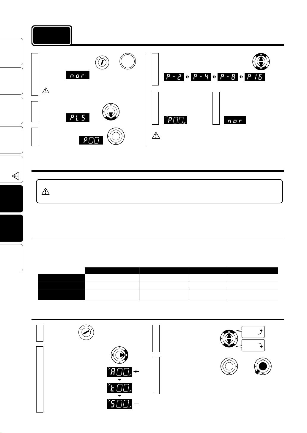
procedure 4
Speed Pulse Settings
For details about Pulse settings, see the “Wiring
Chart ” .
Using
Before
1
Features
2
The Wires
Connecting
3
Installing
The Product
Settings
Initial
Settings
Speed Pulse
How to
Operate
Trouble-
Shooting
Turn the ignition to
the ON position.
(Engine not running)
•
will
nor
appear.
Press the DOWN switch
for 3 seconds.
•
PLS
appear.
Release the DOWN switch.
• The pu lse num ber
will appear.
(NORMAL Mode)
If
does not a ppear, press the
nor
MODE switch until
will
nor
appears.
ON
or
Withou t press
the clut ch, pre ss
down twice
Press the
switch for
3 seconds
ENGINE
START
STOP
Release
Press the UP / DOWN switches to select
4
the desired pulse setting.
(Factory Setting)
If no operation is
carried out for 3 seconds, the display will
begin blinking.
If no operation is carried out
65
for 5 seconds, the display
will change from blinking to
NORMAL Mode.
Setting
Completed
Make sure to set the car’s speed pulse settings correctly. If the
pulse settings are incorrect, the Auto-Blipping will not work with
the setting speed.
Press
Operating the Auto-Blipping
• Since Auto- Blipping is a useful function for sports driving, please set to OFF in the city.
• If it is slightly accelerated when releasing the clutch pedal, please adjust Auto-Blipping setting values lower
because the values might be too high.
BLIPPING is the action to increase Engine Rotation which decreased by braking. When using blipping to
raise the Engine Rotation, it is possible to fine tune the settings for degree of acceleration, time length
of operation and the speed at which blipping starts.
Adjusting Auto-Blipping
Although amount of increase in engine rot ation on Auto-Blipping is different by car per formance and driving conditions, basically it could
be the most suitable settings that cause less acceleration and deceleration when releasing the clutch pedal in addition to downshift
smoothly.
In operation of Auto-Blipping with 3rd gear and about 3000r pm, basically Engine Rotation will inc rease about 1000rpm.
[Value of settings]
Degree of acceleration
Time le ngth of o peration
The minimum speed of
blipping start
Range of settings
30–50 %
0.2–0.6 sec
30–60 km/h
Adjustment unit
10 %
sec
0.1
10 km/h
30 %
0.2 sec
30 km/h
Basic value of setting sInitial value
40–50 %
0.3– 0.5 sec
50 km/h
8
Adjust Please in crease gradually from the minimum adjustment.
Engine Start.
1
Press the SET switch to
2
select the desired setting
mode.
(Blinking)
Degree of acceleration
(30– 50 %)
Time length of operation
(0.2–0.6 sec)
The spe ed at which
blipping starts
(30–60 km/h)
START
Press
Press the UP / DOWN
3
switches to select the
desired setting.
Back to normal display
4
with no operation for 3
seconds or pressing
the BLP switch.
Setting Completed
Values
Up
Values
Down
or
3 seconds
Page 9
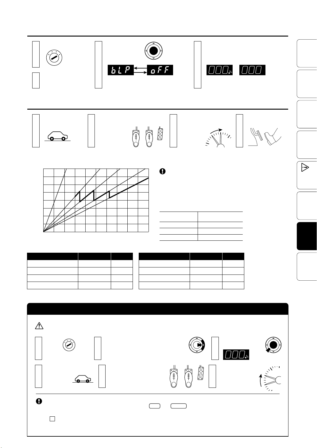
6
5
4
3
Set When the engine starts, Auto-Blipping is OFF. Need to tur n ON when it used.
1st
2nd
3rd
4th
5th
Engine Start.
Mode Display
2
START
Change with each
341
pressing of the
BLP switch.
Auto-B lipping
ON
Press
Auto-B lipping
OFF
Activate Depress the Clutch while step ping on t he brake, blippin g works automatically.
Start Running.
1
(Settin g speed or above.)
[Reference 1] Speed and rpm of each gear (SUZUKI SWIFT ZC31S)
Engine Rotatio n (rpm)
8000
7000
6000
5000
4000
3000
2000
1000
1st
1st 2nd
0
20 40 60 80 100 120 140 160 180 200
2nd 3rd
[Reference 2] Example of settings
Car model
Vitz
86/BRZ
CR-Z
Civic(FD2) 0.4 sec
Depress the clutch
234
while stepping on
the brake.
Auto-Blipping
function operate.
(The rpms increase.)
Settings of the car with standard “Acceleration
3rd 4th
Degree of
acceleration
30%
40%
40%
40%
4th
Time
0.3 sec
0.3 sec
0.3 sec
5th
5th
Speed (km/h)
Car model
IMPREZA(GRB)
SWIFT(ZC31S) 30%
COLT
switching function” .
Note: “Acceleration switching function” is about a standard
function which switches acceleration like SUBARU SI drive and
HONDA 3- mode dr ive system .
Since the amoun t of increase in en gine rot ation c hange s
depen ding on the car set ting mode, ple ase adjust blipping
setti ngs acc ordin g to the set ting mode.
e.g. HONDA CR -Z 3-mod e drive sys tem
Sett ing mod e of
car side
NORMAL 1000rpm
SPORT
ECON
Degree of
acceleration
Back to normal display with no
operation for 3 seconds.
Note: You can che ck the O N / OFF, by checki ng
the dot li ghting or not on no rmal di splay.
Dot light onONDot light off
OFF
Release the clutch.
(Downshift completed.)
6
5
7
4
Amount o f incre ase
in engine rotation
180 0rpm
400rpm
Time
40%
30%ROADSTER(NCEC)
30%
0.3 sec
0.3 sec
0.4 sec
0.4 sec
Before
Using
Features
Connecting
The Wires
The Product
Installing
Settings
Initial
Speed Pulse
Settings
Operate
How to
Shooting
Trouble-
Auto-Blipping Test
After having carried out all of the necessary wiring and making settings in “Initial Settings” and
“Speed Pulse Settings” please carry out a Auto-Blipping test.
Please carry out the test drive in a safe spacious area away from pedestrians and traffic.
Please make sure to carefully read this manual and understand how to operate the unit before taking a test run.
Engine
1
Start.
Start the Test Run.
4
(40 km/h, not lower
than 3rd gear)
START
If Auto-Blipping will
not operate
Check t he right if Auto- Blip ping will not
work at .
6
Press the SET switch to make each setting.
2
(Test setti ng value s: A30, t 0.2, S30)
See page 8
56
to
9 for details.
Depress the clutch pedal
while stepping on the brake.
(When pr essin g the clut ch, the sp eed
must be not lower than 30 km/h.)
• Poor settings of “ Initi al Settings” and “Speed Pulse Settings” . (See page 7 to 8)
• Poor connection of and . (See page 4 to 5)
• Poor connection of Clutch adapter. (See page 4)
• Not reached at the set speed. (See page 8)
• Auto-Blipping setting value is too low. (See page 8 to 9)
• Not enough to press the Clutch pedal.
Gray Or
ange
Press the BLP switch.
3
(Make sure t he dot bli nks.)
Auto -Blipping
function operate.
(The rpms increase.)
6
5
4
3
2
9
Page 10
Using
0
%
100
%
Before
Features
The Wires
Connecting
Installing
The Product
Initial
Settings
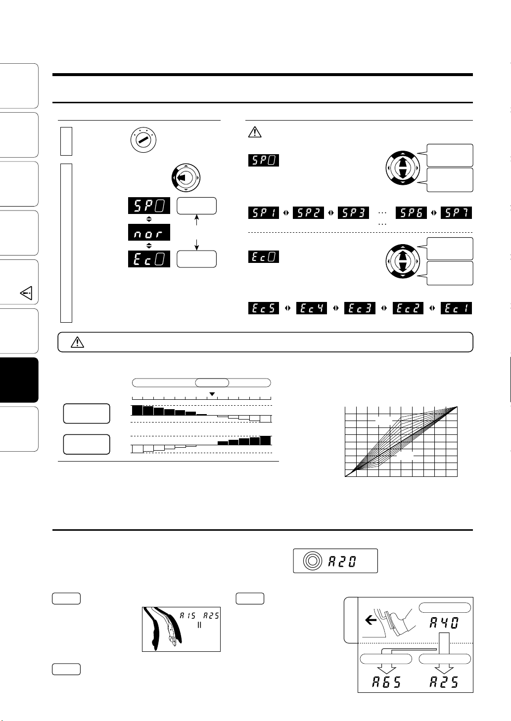
Operating the Throttle Controller
Switching Response Levels Make settings for response in each Mode.
Switch the Mode Adjust the Change Ratio for each Mode
Engine Start.
1
The Mode will change
2
with each pressing of
START
the MODE switch.
SPORTS Mode
NORMAL Mode
ECO Mode
Note: For safety, when changin g modes always go
through
(NORMA L) one time.
nor
Press
Higher
Response
Normal
Conditions
Lower
Response
When making adjustments to the change ratios, begin at the lowest
setting and slowly make changes while continually checking acceleration.
• Switch the Change Ratio for SPORTS Mode
is displayed, the ratio will
change with each pressing of the
UP / DOWN switch.
Smallest
Change Ratio
(+30%)(+20%) (+60%)
• Switch the Change Ratio for ECO Mode
is displayed, the ratio will
change with each pressing of the
UP / DOWN switch.
Greatest
Change Ratio
Greatest
Change Ratio
(
side)
SP7
Lowest
Change Ratio
(
side)
SP1
Greatest
Change Ratio
(+70%)(+10%)
Lowest
Change Ratio
(
side)
Ec1
Greatest
Change Ratio
(
side)
Ec5
Smallest
Change Ratio
(−10%)(−50%) (−30%)(−40%) (−20%)
Settings
Speed Pulse
How to
Operate
Trouble-
Shooting
10
Saving Settings
[Reference 1] Examples of changes in fuel consumption and
RESPONSE
EFFICIENCY
Note: In ECO Mo de, bec ause response is less t han the st andar d fuel ef ficiency
response depending on change ratios
MODE
Good
Bad
FUEL
can be improved. However, if rapid acceleration is purposefully carried
out fuel effic iency will be red uced.
The changes in re spons e will be gr eater as the vehicle’s power is greater.
Good
Bad
Degree of Acceleration Monitor
Degree of Acceleration Monitor shows the rate of acceleration output to the ECU where 0 represents the pedal not being pressed in and 100
equals when the pedal is fully pressed down.
Note: Depending on charac teristics of the accelerator or on how the accelerator is stepped on the dis play may read up to 95%.
Check acceleration during ECO driving
USE
1
To ensure reduced fuel
consumption during acceleration the degree of acceleration
should be between 15% and
25%. To further improve results
use ECO Mode when wishing
to save fuel.
Check acceleration during regular driving
USE
2
Please use to check the degree of acceleration for any type of
driving, not just ECO Mode.
All settings are saved even after the ignition has been turned to the OFF position. However, if the ignition is
turned OFF in 5 seconds or less after the last setting operation was carried out, the settings will not be saved.
[Reference 2] Basic Control Features
The changes throughout each Mode will be
SPORTS
7654321
NORMAL
ECO
12345
controlled smoothly without perceptible steps.
Acceleration output signal based on amount of
pressure placed on accelerator pedal
Acceleration Output Signal
(at degree monitor)(%)
100
SP7
50
Ec5
10
100
0
Displays the amount of pressure placed on the accelerator pedal.
(output signal) [15–100%, 5% unit]
Degree of Acceleration
(output) 20%
Check control status
USE
3
-
=
%
0
%
ECO
With the ignition in the ON position
(engine not running) and under
NORMAL Mode press in the pedal
until it reaches 40% (
Mode is changed to
should read 65% (
the display should change to
in
Ec5
).
25% (
A25
[See the above Graph of “Basic
Contro l Features ”] Note: Th e actual
display may differ slightly.
A40
the display
SP7
) and if placed
A65
), if the
e.g.
Press down on pedal.
40
%
40%
Switch Mode to
50 100
Amount of pressure placed on
the accelerator pedal (%)
In NORMAL Mode
Switch Mode to
SP7
Ec5
Page 11
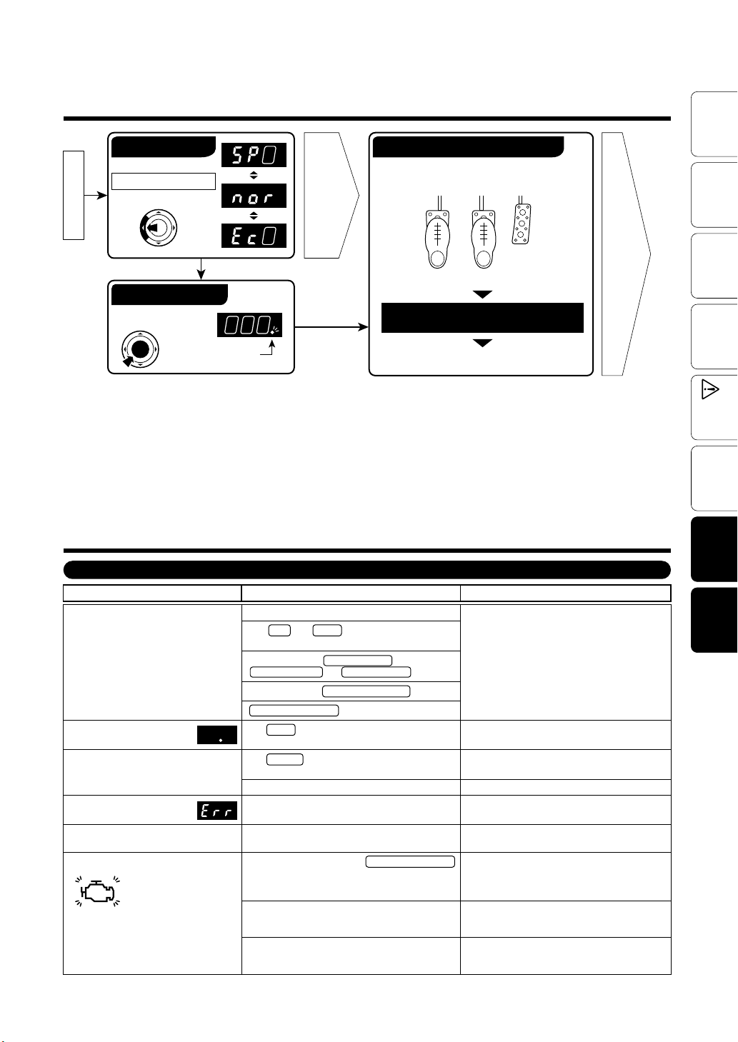
Basic Operation
Before
Using
Engine Start
Switching the Mode
Press the MODE switch.
Auto-Blipping ON
Throttle Control
Press the BLP Switch
Dot ligh t on : ON
Dot ligh t off : OFF
Troubleshooting
Page 10
Auto-Blipping function operate
Depress the clutch while stepping on the
brake with setting speed or above.
Accel
Clutch Brake
Auto-Blipping function operate.
(The engine’ s rpms increase.)
Change gear and release the clutch
pedal, downshift completed.
Page
8 to 9
Features
Connecting
The Wires
The Product
Installing
Initial
Settings
Speed Pulse
Settings
Operate
How to
Concerning Basic Operations and Car Problems
Trouble
The ignition is set to the ON position but
the display of the M ain Uni t will not l ight
up.
OR the display go es OFF whi le in use.
With the igniti on switched to
the ON, only the dot appears.
It will not go into “Initia l Setti ngs” or
“Speed Pulse Settings”.
While making “Initial Settings”
appears in the display.
an
Err
appears in the display and won’t work.
nor
A Check En gine Li ght has gone on.
Brake fuse is burned out.
The RED and Black w ire may have be en improperly wired or ther e is a poor c onnec tion.
Poor connection of 5-pin Connector ,
8-pin Connector and 6-pin Connector .
Poor connection of Specialized Harness .
Specialized Harness being used is incorrect.
The Black wire may have been improperly wired or
there is a poor connection.
The Orange wire may have been improperly wired
or there is a poor connection.
The car is being dr iven.
The “Initial Se ttings” have not been pro perly c arried
out.
The “Initial Se ttings” have not been pro perly c arried
out.
The accelerator connector or Specialized Harness
was disconnected with the ignition in the ON position
or within 15 minutes after having turned the ignition
to the OFF position.
The “Initial Se ttings” have not been pro perly c arried
out.
The prod uct was i n a mode ot her than NORMAL
Mode when removed from a car and installed into a
different car.
Possible Causes Possible Solutions
Please reconfi rm whet her wiri ng and co nnections
are correct or not.
Please reconfi rm whet her wiri ng and co nnections
are correct or not.
Please reconfi rm whet her wiri ng and co nnections
are correct or not.
Carry o ut after stoppi ng the ca r.
Make the “ Initial Settings” (Se e page 7 of th is
manual).
Make the “ Initial Settings” (Se e page 7 of th is
manual).
Re-connect the disconnected connector and turn
off the L ight (See p age 12 of this m anual).
Make the “ Initial Settings” (Se e page 7 of this
manual) and turn off the Ch eck Eng ine Light (See
page 12).
After returnin g it to NORM AL Mode, carry out the
“Initial Set tings ” (See page 7 o f this manual) and
turn off the Check Engin e Light (Se e page 12).
Shooting
Trouble-
11
Page 12
Using
Before
Features
The Wires
Connecting
Installing
The Product
Settings
Initial
Settings
Speed Pulse
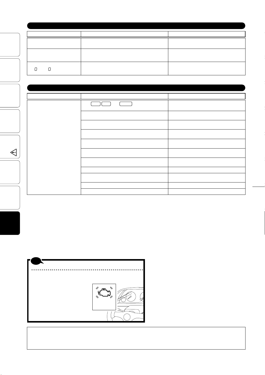
Concerning the Throttle Controller
Trouble Possible Causes Possible Solutions
Even if the Mode is changed, the
changes cannot be felt.
The Mode and/or the setting of
change ratios can not be saved.
With the ignition in ON position,
or
Ec
change to nor.
in display and
SP
The “Initial Settings” have not been properly carried out.
The ignition has been turned to the OFF position
immediately after having finished the setting of change
ratios or changing the Mode.
The “Initial Settings” have not been properly carried out.
Concerning Auto-Blipping
Trouble Possible Causes Possible Solutions
Auto-Blipping will not operate.
The and wires may have been
improperly wired or there is a poor connection.
The clutch adapter may have been improperly wired.
“Speed Pulse Settings” have not been properly carried out.
The “Initial Settings” have not been properly carried out.
“Auto-Blipping” have not been turned on.
“Auto-Blipping Settings” have not been properly carried out.
The speed is lower than the setting value.
Clutch canceller is installed.
Have not pressed brake pedal from starting engine before
operating Auto-Blipping.
Not enough to press the Clutch pedal.
The brake lamp bulbs have been changed to LED lamp bulbs.
Gray Pink Orange
Make the “Initial Settings” (See page 7 of this
manual).
After having made settings of change ratios or
changing the Mode, wait for at least 5 seconds
before turning the ignition to the OFF position.
Make the “Initial Settings” (See page 7 of this
manual).
Please reconfirm whether wiring and connections
are correct or not (See page 4 to 5 of this manual).
Please reconfirm whether wiring and connections
are correct or not (See page 4 of this manual).
Make the “Speed Pulse Settings” (See page 8 of
this manual).
Make the “Initial Settings” (See page 7 of this
manual).
Please reconfirm how to operate Auto-Blipping (See
page 8 to 9 of this manual).
Please reconfirm “Auto-Blipping Settings” (See page
8 to 9 of this manual).
Please reconfirm “Auto-Blipping Settings” (See page
8 to 9 of this manual).
May need to remove it.
Press the b rake ped al before operat ing Auto Blipping.
Depress the clutch pedal deeper.
Replace with standard brake lamp bulbs.
How to
Operate
Trouble-
Shooting
Note
How to Turn Off the Check Engine Light
If the Check Engine Light comes on due to some operational mistake,
please follow the directions be low to turn it off.
1. Under normal conditions, start and
stop the engine several times.
2. If that does not turn off the lamp,
disconnect the cable from minus
terminal of the battery for about 10
minutes.
3. If that does not turn off the lamp,
please consult your local car dealer
and have them turn it off.
• Our products have already been recognized as our Industrial Proper ty or are in the process of receiving Industrial Proper ty status.
(Note)
• We plan in the near future to take all possible legal measures to prote ct against unfair competition from look-alike products using
similar d esigns, regulating characteristic s, circuitry and circ uitry layout.
• We strict ly prohibit the unlicensed use of the PIVOT trademark and the unauthorized use of PIVOT User’s Manual.
Check Engine
Light is ON
12
PIVOT CORPORATION
87-3, Shimookada Okada, Matsumoto-shi, Nagano, 390-0313 Japan
 Loading...