

Page 1
DA50S/DA55S and DA70S/DA75S
AddressRight™ Shuttlehead Printers
DA50S (WS51) - Black
DA55S (WS56) - Black & Color
DA70S (WS71) - Black
DA75S (WS76) - Black & Color
Service Manual
Page 2

FCC Compliance
This equipment had been tested and found to comply with the limits for a Class A digital device,
pursuant to Part 15 of the FCC rules. These limits are designed to provide reasonable protection
against interference when the equipment is operated in a commercial environment. This equipment
generates, uses, and can radiate radio frequency energy, and if not installed and used in accordance
with the users manuals, may cause harmful interference to radio communications. Operation of this
equipment in a residential area is likely to cause harmful interference in which case the user will be
required to correct the interference at his own expense.
Shielded cables must be used with this unit to insure compliance with Class A limits.
Canadian DOC Compliance
This digital apparatus does not exceed in the Class A limits for radio noise emissions from digital ap-
paratus set out in the Interference-causing Equipment Regulations (Standard ICES-003) of the Canadian Department of Communications.
Le present appareil numerique n’emet pas de bruits radioelectriques depassant les limites applicables aux appareils numeriques de la class A prescrites dans le Reglement sur le brouillage radioelectrique edicte par le ministere des Communications du Canada.
NOTE: This equipment has been tested and found to comply with the U.S. Standard for Safety
UL1950, Third Edition, Safety of Information Technology Equipment including Electrical Business
Equipment and Canadian Standards C22.2 No 950-95, Third Edition, Safety of Information Technology Equipment including Electrical Business Equipment
First Edition, March 2007
SV61831 Rev. A
©2007 Pitney Bowes Inc.
All rights reserved. This book may not be reproduced in whole or in part in any fashion or stored in a
retrieval system of any type or transmitted by any means, electronically or mechanically, without the
express written permission of Pitney Bowes Inc.
We have made every reasonable effort to assure the accuracy and usefulness of this manual, however, we cannot assume responsibility for errors or omissions or liability for the misuse or misapplication of our products.
Page 3

Table of Contents
Chapter 1 – Introduction
1.1 Purpose of this Manual .............................................................. 1-1
1.2 Related Publications .................................................................. 1-1
1.3 Book Organization ..................................................................... 1-2
1.4 Safety ........................................................................................ 1-2
Chapter 2 – Specifi cations
2.1 Product Description ................................................................... 2-1
2.2 System Requirements ............................................................... 2-1
2.3 Physical Equipment Specifications ............................................ 2-2
2.4 Print Specifications .................................................................... 2-3
2.5 Material Specifications............................................................... 2-7
Chapter 3 - Theory
3.1 Changes From Earlier Models .................................................. 3-1
3.2 Printer Architecture .................................................................... 3-2
3.3 Operating Sequence.................................................................. 3-5
Chapter 4 - Troubleshooting/Diagnostics
4.1 Block Diagrams ......................................................................... 4-1
4.2 Main Controller Board Diagnostics ............................................ 4-3
4.3 Troubleshooting Tables .............................................................. 4-7
4.4 Printer Error Codes.................................................................. 4-14
4.5 Print Samples for Troubleshooting .......................................... 4-15
Chapter 5 - Removal & Replacement
5.1 List of Procedures...................................................................... 5-1
DA50S/DA55S (WS51/WS56) Parts Removal
5.2 Covers ...................................................................................... 5-2
5.3 Display/Keyboard ..................................................................... 5-3
5.4 Main Processor Board/Grounding Sheet Assembly ................. 5-3
5.5 USB/Ethernet Input Board ........................................................ 5-4
5.6 Power Supply ........................................................................... 5-5
5.7 Paper Transport Motor/Belt ...................................................... 5-7
5.8 Sensor ...................................................................................... 5-9
5.9 Feed Roller Assembly ..............................................................5-11
5.10 Encoder and Operator Side Drive Belt ................................. 5-13
DA50S/DA55S/DA70S/DA75S AddressRight™ Printers Service Manual
iii
Page 4

Table of Contents
Chapter 5 - Removal & Replacement (continued)
DA70S/DA75S (WS71/WS76) Parts Removal
5.11 Covers .................................................................................. 5-15
5.12 Display/Keyboard ................................................................. 5-17
5.13 Main Processor Board/Grounding Sheet Assem. ................. 5-17
5.14 USB/Ethernet Input Board .................................................... 5-18
5.15 Power Supply ....................................................................... 5-18
5.16 Feed Roller Assembly............................................................ 5-19
5.17 Motor Drive Belts and Main Motor ........................................ 5-21
5.18 Exit Roller ............................................................................. 5-23
5.19 Sensor .................................................................................. 5-23
5.20 Shuttle Head Motor, Print Head, Shuttle Drive ..................... 5-24
5.21 H-Block Tip ........................................................................... 5-25
Chapter 6 - Adjustments
6.1 List of Adjustments .................................................................... 6-1
Adjustments for All Models
6.2 LCD Display .............................................................................. 6-2
6.3 Paper Sensor Test and Calibration ........................................... 6-2
DA50S/DA55S (WS51/WS56) Adjustments
6.4 Main Brake ............................................................................... 6-3
6.5 Printhead Clearance .................................................................. 6-5
6.6 Adjusting Exit Roller Idler Assembly .......................................... 6-6
6.7 Printhead Drive Belt .................................................................. 6-7
6.8 Main Drive Belt .......................................................................... 6-8
6.9 Adjusting Service Station Assembly .......................................... 6-9
DA70S/DA75S (WS71/WS76) Adjustments
6.10 Main Brake ............................................................................ 6-10
6.11 Print Head Drive Belt ............................................................. 6-10
6.12 Timing Belt .............................................................................6-11
6.13 Main Drive Belt .......................................................................6-11
6.14 Print Head Home Position ..................................................... 6-12
iv SV61831 Rev. A DA50S/DA55S/DA70S/DA75S AddressRight™ Printers Service Manual
Page 5

Table of Contents
Chapter 7 - Maintenance Procedures
7.1 General ...................................................................................... 7-1
7.2 Specific Maintenance ................................................................ 7-2
Appendix A – Printer Control Panel Menus and Utilities
A.1 Control Panel Menus for the Printer ..........................................A-1
A.2 LCD Control Panel Menu .........................................................A-3
A.2 LCD Main Menu .......................................................................A-4
A.3 LCD Setup Menu.......................................................................A-9
A.4 LCD Service Menu .................................................................. A-19
A.5 Setting Factory Defaults (from LCD Menu) ............................. A-24
A.6 Updating Firmware ..................................................................A-26
Appendix B – Printer Communications
B.1 Communication Scenarios ........................................................B-1
B.2 Troubleshooting Tables .............................................................B-4
B.3 Testing Printer Communications Within a Network ...................B-7
Appendix C – Schematics
Main Processor Board Schematic ....................................................C-2
LCD/Keypad .....................................................................................C-3
USB/Ethernet LAN Function .............................................................C-4
Black & White Printer Head ..............................................................C-5
Color Print Head ...............................................................................C-6
Index (not ready at time of publishing) ........................ I-1
DA50S/DA55S/DA70S/DA75S AddressRight™ Printers Service Manual
v
Page 6

Table of Contents
vi SV61831 Rev. A DA50S/DA55S/DA70S/DA75S AddressRight™ Printers Service Manual
Page 7
1 • Introduction
1.1 Purpose of
this Manual
This book contains instructions for troubleshooting and site repair of DA50S/
DA55S and DA70S/DA75S AddressRight™ shuttlehead printers. It also includes
complete product specifications and a section on theory for training purposes.
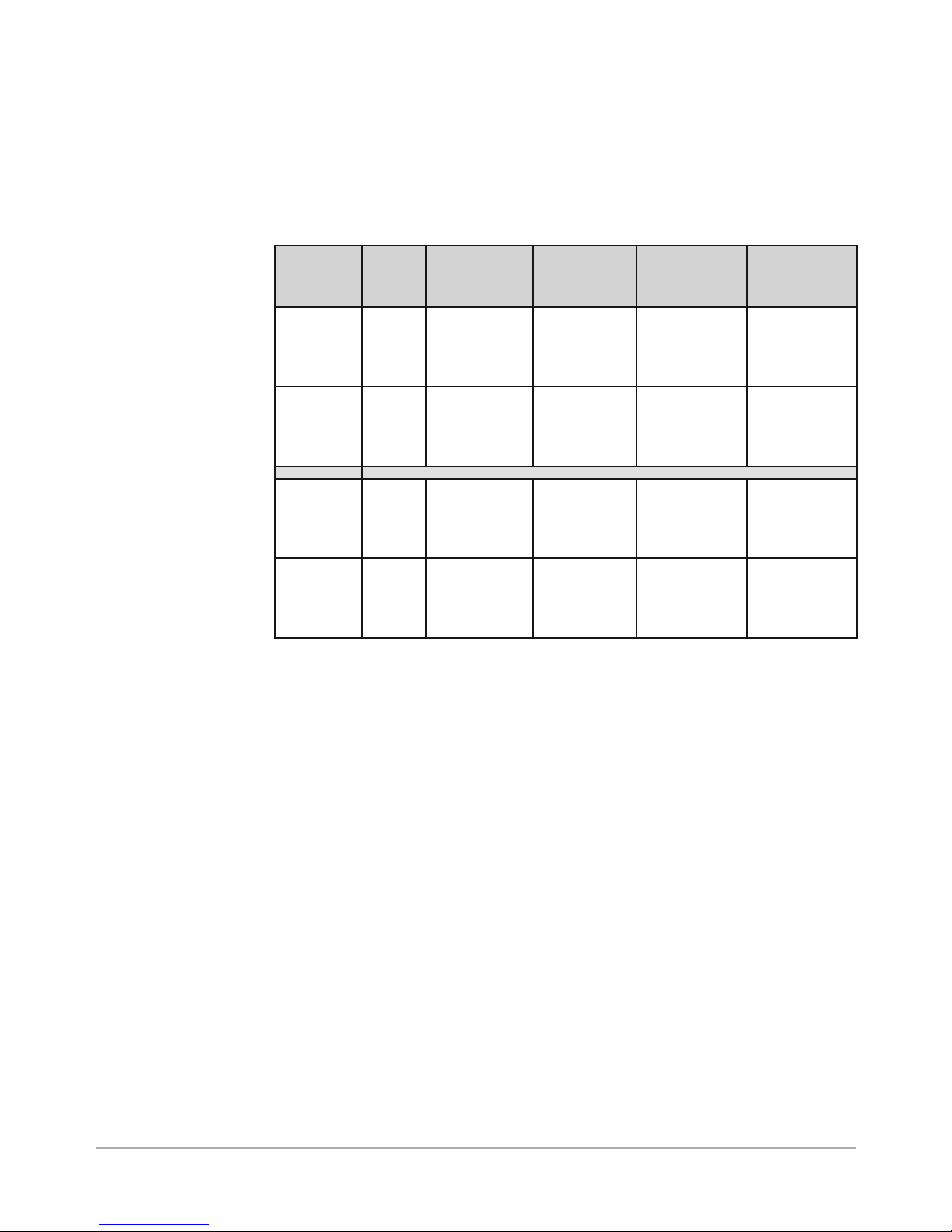
For reference, the table below shows the predecessor shuttle head models.
New
Marketing
Model
DA50S WS51 Black Up to 10,000
DA55S WS56 Black & Pro-
DA70S WS71 Black Up to 14,000
DA75S WS76 Black & Pro-
New
PCN
Printing
Capability
cess Color
(CYMK)
cess Color
(CYMK)
Speed Predecessor
Marketing
Model
DA500 W660
#10 or DL
envelopes
per hour
Up to 10,000
#10 or DL
envelopes
per hour
#10 or DL
envelopes
per hour
Up to 14,000
#10 or DL
envelopes
per hour
DA550 W680
DA700 W707
DA750 W790
Predecessor
PCN
1.2 Related
Publications/
Information
DA50S/DA55S Operator Guide SV61663
DA50S/DA55S Quick Setup Instructions (customer) SV61933
DA50S/DA55S Install SV61664
DA50S/DA55S Parts List SV61832
DA70S/DA75S Operator Guide SV61665
DA70S/DA75S Quick Setup Instructions (customer) SV61934
DA70S/DA75S Install SV61666
DA70S/DA75S Parts List SV61919
For other information on the printers, refer to these sources:
• Software Control Panel Application (on the host PC) - see the help sys-
tem on the software.
• FAQs document - see the Customer Service website under the product
page for AddressRight™ printers.
• Training - see Enhanced AddressRight™ Shuttle Head Printers Self-Directed Course (GMS-MC-03246) at My Portfolio on the Pitney Bowes intranet.
• Training Job Aids - print the job aids for the software control panel appli-
cation (GMS-MC-03246JA) at My Portfolio on the Pitney Bowes intranet.
DA50S/DA55S/DA70S/DA75S AddressRight™ Printers Service Manual
1-1
Page 8

1 • Introduction
1.3 Book
Organization
1.4 Safety
Chapter 1: Introductory and safety information
Chapter 2: Product specifications
Chapter 3: Theory of operation
Chapter 4: Troubleshooting and Diagnostics
Chapter 5: Removal and replacement procedures
Chapter 5: Adjustment procedures
Chapter 7: Maintenance procedures
Appendix A: Printer Control Panel Menus
Appendix B: Printer Communications
Appendix C: Schematics/Diagrams
Warning messages appear throughout this manual to alert you to potentially
hazardous con di tions. Two designations indicate their relative seriousness:
WARNING! Calls attention to improper practices that
could result in a potentially serious, even lethal injury to
you or the customer.
CAUTION! Calls attention to practices that could
cause minor injury to you or a customer or that could
damage equipment or material.
Familiarize yourself with proper procedures and methods before you install,
operate or re pair the equipment to avoid personal injury or damage to the
equipment. If you train service peo ple or equip ment operators, it is important to
explain safety precautions to your students and en cour age safety awareness.
Personal Safety
Follow these precautions for your own safety:
• Treat every circuit like a gun that may be loaded. It may not be “live,” but
be sure. Check with a neon tester or voltmeter, or simply unplug the machine.
• Know how to turn off the power in the work area and get help in an emer gen cy.
• Don’t work on equipment under power unless it’s absolutely necessary.
If you must, use extreme cau tion. Don’t grasp two sides of a live circuit
at the same time—use one hand when reach ing into a cir cuit, touching
a ground ed case or chas sis with that wrist or el bow if pos si ble. This pre vents cur rent from passing through vital organs. Observe this rule when
con nect ing or dis con nect ing plugs or leads, or mak ing any adjustments
on a live cir cuit.
1-2 SV61831 Rev. A DA50S/DA55S/DA70S/DA75S AddressRight™ Printers Service Manual
Page 9

Introduction • 1
1.4 Safety
Personal Safety (continued)
• Don’t un der es ti mate the danger of shock: 1 mA (1/1000 amp) is un com fort able; 5 mA is dan ger ous —you may jump back and be injured; 12 mA
causes hand muscles to con tract, so you can not free your self; 24 mA has
proven fatal; and 100 mA (1/10 amp) is likely to be fa tal.
• Use the right tools for the job. A tool which slips can cause a short—or a
shock. Don’t reach into a circuit with metal tools, or while wearing rings or
a watch. Even in low voltage cir cuits, a metal object can short circuit two
terminals. When work ing on live cir cuits, use tools with in su lat ed handles
and try to keep your tool hand grounded.
• Don’t bypass safety devices, particularly fuses. Three-wire outlets (120
Vac) are designed to ground equipment to make it safe. If a hot wire
shorts to a grounded frame, the only result is an open fuse. If a hot wire
shorts to an ungrounded frame, the frame itself be comes hot and po ten tial ly dangerous. A fuse is a weak link in a circuit, de signed to break down
before any thing else does. The maximum safe cur rent in a circuit is de ter mined by the de sign ers. Too large a fuse can pass excessive current,
dam ag ing expensive equipment.
• For electrical fires, use Type C, BC or ABC extinguishers only. Don’t use
soda acid or other liq uid stream extinguishers. They will damage elec tri cal equipment and present a shock hazard to the user.
• Digital equipment can be easily damaged or destroyed by static charges.
Mi cro pro ces sors and other integrated circuits con tain tiny transistors not
much more than a mil lionth of an inch across, which operate at 5 to 12
volts.
• Be extremely careful when lifting heavy equipment. Follow the guidelines
below:
a. Squat to lift and lower. DO NOT bend at the waist.
b. Keep your low back bowed in while bending over.
c. Keep the weight as close to you as possible.
d. Bow your back in and raise up with your head first.
e. If you must turn, turn with your feet, not your body.
f. Never jerk or twist!
g. Put the weight down by keeping your low back bowed in.
h. Keep your feet apart, staggered if possible.
i. Wear shoes with non-slip soles.
j. Get help if you need it.
DA50S/DA55S/DA70S/DA75S AddressRight™ Printers Service Manual
1-3
Page 10

1 • Introduction
1.4 Safety
Electrostatic Discharge ( ESD) Procedures
Follow these guidelines to protect sen si tive equipment from static damage:
• Always use a wrist grounding strap and anti-static mat when working on
equipment sensitive to electrostatic discharge. These items are furnished
in the ESD Field Service Kit, L-8351.
• Ground yourself before reaching into the equip ment, or touch ing any
circuit board or other electrical component. Just touch ing a doorknob or
metal work bench may be enough, but the best guarantee is to turn the
machine off but leave it plugged in, and ground your self on the chassis,
which is grounded through the three-wire power cord.
• Be careful of rugs—even a few steps can recharge you. Re-ground yourself whenever you’ve walked away and re turned to the ma chine. Rugs
are a major source of static build up in the body.
• Take greater precautions as the objects you handle get smaller. A board
in the machine is better protected than one that is not plugged in; a chip
on a board is better protected than one in your hand.
• Stay away from metal conductors. The plastic and resin that chips and
boards are made of are much better insulators than metal. It’s most important to keep your hands away from any metal which contacts the data.
In particular, this means the long connector along the bottom of each
board, and the pins coming out of the chips. These signal and data lines
are directly connected to the fragile inner circuits of the chips. When handling a board, try not to touch the connector; when handling a chip, try
not to touch the pins.
1-4 SV61831 Rev. A DA50S/DA55S/DA70S/DA75S AddressRight™ Printers Service Manual
Page 11

2 • Specifications
2.1 Product
Description
2.2 System
Requirements
The DA50S/DA55S and DA70S/DA75S ink jet printers are shuttle type desktop models used to print addresses, graphics and other information, in black
(DA50S & DA70S), or black and color (DA55S & DA75S); on a wide range of
material sizes, construction and composition. The operator can define the font,
placement, print quality and bar code characteristics for the printed addresses.
Customer PCs must meet the following minimum requirements:
• CPU: Pentium III 500MHz. or greater, 500MB RAM or more preferred
• Operating System: Windows 2000/2003 Server/XP (not yet tested on Vista)
• USB Cable or Ethernet Cable: A USB cable is supplied with the printer. If
the customer chooses to use another cable, it must be no longer than 15
feet (5m).
For the Control Panel software, the following is required:
• Win2K SP4, WinXP Pro SP2, Win Server 2003 SP1 w/ latest Service
Pack (not yet tested on Vista)
• Dot Net v1.1
• 5MB Disk space
• Administrative rights to install software
2.3 Physical
Equipment
Specifications
Physical Dimensions
DA50S/DA55S:
14.7” (37.3 cm) high; 16.2” (41.2 cm) wide; 21.7” (55.1 cm) deep (without
input guide).
DA70S/DA75S:
13” (33 cm) high; 19” (48 cm) wide; 17” (43 cm) deep (without input guide).
Weight
DA50S/DA55S:
44.11 lbs. (20 kg), including print cartridges (B & C) and catch bin.
DA70S/DA75S:
50 lbs. (23 kg), including high-capacity print cartridges and catch bin.
Electrical
Domestic: 120VAC, 60Hz, 1A; International: 220-240VAC, 50Hz, 0.5A
Fuse Type: 1 Amp Slo-Blo 250VAC (on Main Circuit Board)
Power Consumption: 126 Watts, 430 BTU/hr.
Agency Approvals
UL/cUL/VDE-GS - Refer to the FCC and CE statements at the front of this
manual for more information.
DA50S/DA55S/DA70S/DA75S AddressRight™ Printers Service Manual
2-1
Page 12

2 • Specifications
2.3 Physical
Equipment
Specifications
Interface
USB, Ethernet
Control Language
PCL5, modified
Address Recovery
Memory buffer holds a maximum of 99 addresses
Environmental Limits
Operating Conditions
• Temperature: 55 to 95°F (12 to 35°C)
• Humidity: 8 to 80%
• Maximum Wet Bulb Temperature: 80°F (27°C)
Storage Conditions
• Temperature (Printer): 42° to 100°F (5 to 40°C)
• Humidity (Supplies): 10 to 90% (5 to 95%)
• Maximum Wet Bulb Temperature: 85°F (29°C)
Shipment Conditions
• Temperature (Printer): -40 to 140°F
• Humidity (Supplies): 5 to 100%
• Maximum Wet Bulb Temperature: 85°F (29°C)
Noise Level
DA50S/DA55S
The sound pressure level at the operator’s position for this equipment as
measured in any mode using ANSI and ISO Standards is less than 68 dB(A).
DA70S/DA75S
The sound pressure level at the operator’s position for this equipment as
measured in any mode using ANSI and ISO Standards is less than 72 dB(A).
2-2 SV61831 Rev. A DA50S/DA55S/DA70S/DA75S AddressRight™ Printers Service Manual
Page 13
Specifications • 2
2.4 Print
Specifications
*The Light Mode
printing feature is not
functional at the time
of this writing but is
planned for a future
release.
Print Modes (Print Resolution)
The printers each have three print resolutions. They are Executive (600),
Letter (300), and Draft (150), which represent the horizontal density. Additionally, there are two Light Mode* settings (ON and OFF), which represent
the vertical density. When Light Mode* is "ON", the vertical density setting is
300 DPI; when Light Mode* is "OFF" the vertical density setting is 600 DPI.
Refer to the table below.
Print Quality With Light Mode* set to
"ON"
Executive 600 x 300 DPI 600 x 600 DPI
Letter 300 x 300 DPI 300 x 600 DPI
Draft 150 x 300 DPI 150 x 600 DPI
With Light Mode* set to
"OFF"
Fonts
Resident Fonts
Arial, Comic Sans MS, Courier New, Georgia, Impact, Kino, MSLogo, Symbol, Tahoma, Times New Roman, Trebuchet MS, Verdana, Webdings, Wingding. All fonts are scalable from 4 to 144 point size.
Resident Font Enhancements
Bold, Italic
Downloadable Fonts
Supports bitmapped, downloadable fonts.
Cartridge Fonts
Not Required. Fonts are downloaded with addresses.
User-Definable Parameters
• Font Characteristics
• Address Placement
• Barcode Characteristics
• Print Quality
Barcode Printing Position
The printer can print a barcode in one of three positions:
• Lower right of the envelope (normal printing orientation only- not inverted)
• Above the address block
• Below the address block
DA50S/DA55S/DA70S/DA75S AddressRight™ Printers Service Manual
2-3
Page 14

2 • Specifications
2.4 Print
Specifications
Barcode Printing Types Position
All the printers in the DA Series can print the following barcodes:
1-Dimensional
• USPS Certified POSTNET barcode. All types of barcodes can be printable including FIM, 3 of 9, 4 state barcode (UK, Canadian, Euro, Australia, etc.) and others.
• 5-, 9-, or 11- digit POSTNET barcodes. 5-digit barcode printing may be
disabled through menu selection. NOTE: 5-digit barcode not accessible
from the control panel menu on the printer.
• Delivery point barcode is generated by transmitting the three digits.
• Planet barcode for delivery confirmation services. The printer is also capable of printing any barcode rendered by a Windows® True Type font.
2-Dimensional
The printers are capable of printing a USPS Certified IBIP barcode as well
as all types of 2-D barcodes defined for the countries (UK, Canadian, Euro,
Australia etc.) and others to the defined standards. Reference applicable
Postal Standards.
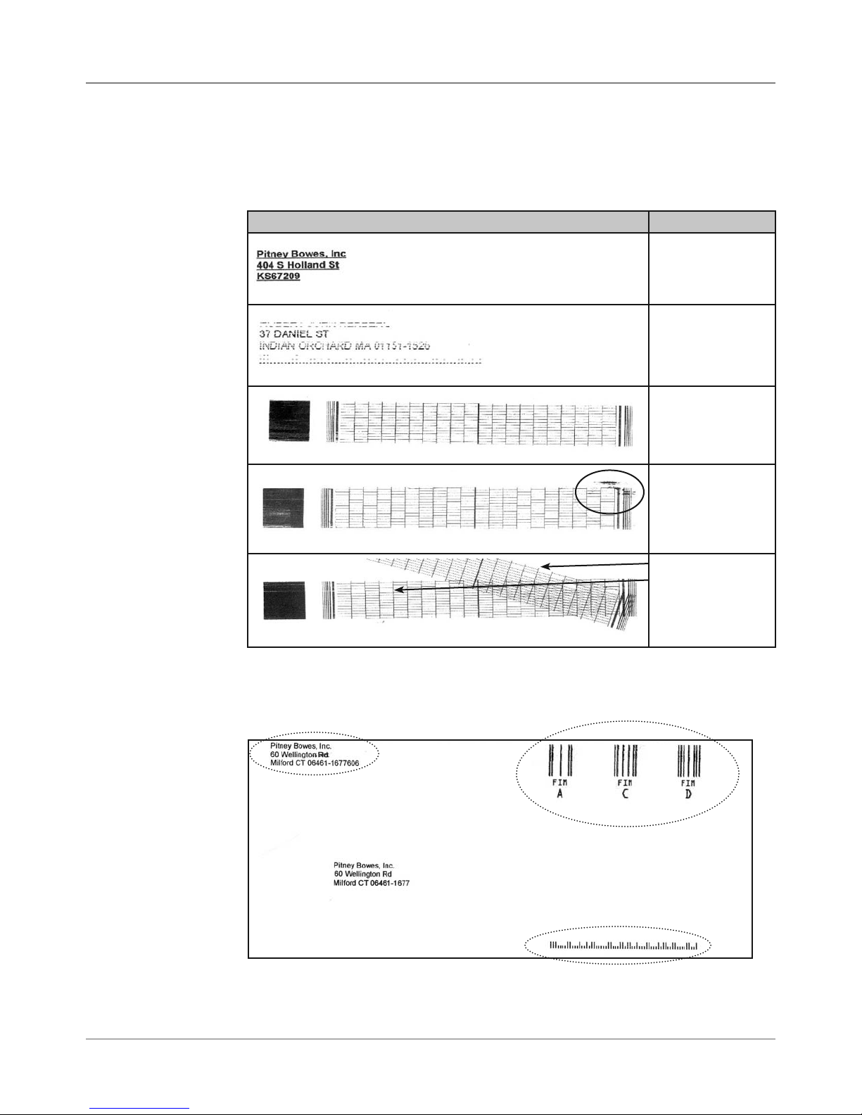
Special Note on FIM Barcode
FIM (Face Identification Marking) barcode was developed by the USPS as
part of their POSTNET barcoding system. It is normally used by high-volume
mailers to put on return envelopes for their customers’ invoices.
When the invoices are mailed back in their return envelope, the USPS sorts
and processes this mail according to what version of FIM barcode is used on
the envelope: FIM A (Postage required, POSTNET bar code included), FIM
C (Postage prepaid, POSTNET bar code included), and FIM D (Postage required, POSTNET bar code not included).
One of the requirements of the FIM barcode is that it needs to be printed
on the edge of the envelope (typically printed in the top right corner). This
is difficult to support by our printers, especially on the trail edge. Inverted
mode may supply a better print for the FIM, but any attempt to print to the
exact edge of the envelope is liable to "miss" the edge occasionally. Because
of these issues, we cannot guarantee full USPS compliance for print-
ing FIM barcode. As a result, some of our high-volume customers used
pre-printed envelopes containing the FIM barcode that meet USPS printing
specifications.
However, if you want to try printing the FIM using our printers, the Pitney
Bowes Envelope Designer Plus software allows you to place a FIM graphic
on the envelope. You can obtain photo-ready graphics directly from the
USPS (the Envelope Designer software itself can not create the FIM barcode
graphic). When printing, use the inverted orientation since the printer is more
accurate at printing items near the leading edge.
2-4 SV61831 Rev. A DA50S/DA55S/DA70S/DA75S AddressRight™ Printers Service Manual
Page 15
Specifications • 2
2.4 Print
Specifications
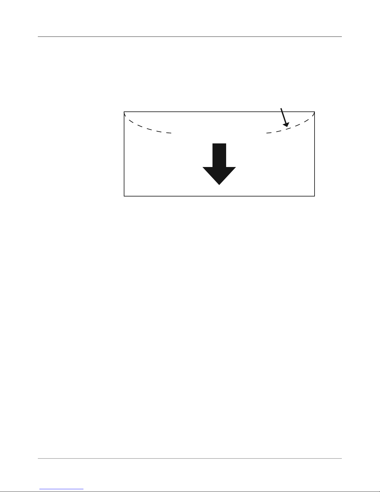
Effective Print Area
The printable width is 9.4" (24cm) measured from the right side of the piece
of mail. The printable height is 15" (38cm) measured from the bottom edge
of the piece of mail. See the figure below.
Flap on Opposite
Trailing Edge (Top)
Feed Direction
Left
Leading Edge (Bottom)
Feed Direction and Print Area
NOTES:
Side
Right
• All edges are viewed from the front surface of the material.
• Two clear zones, each 0.3" (7.6mm) wide, are required on the piece of
mail to allow clearance for the exit rollers.
• Printing is allowed to the top edge of the media, however print quality will
be degraded.
• The lower 5/8" (16mm) of the material is reserved for the lower right barcode when it is used.
DA50S/DA55S/DA70S/DA75S AddressRight™ Printers Service Manual
2-5
Page 16
2 • Specifications
2.4 Print
Specifications
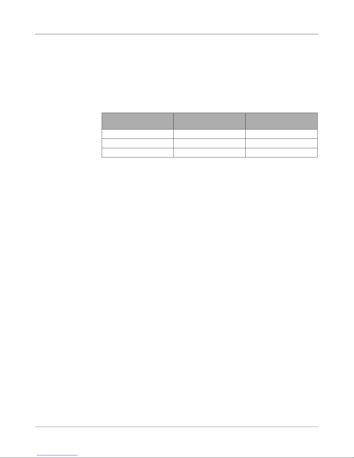
Inkjet Cartridges
Cartridges are operator replaceable. The ink supply cartridges for the
DA50S/DA55S and DA70S/DA75S are the same ones used on their predecessor models (see table on page 1-1). The table below lists some common
order numbers for replacement cartridges. For a complete list of ink cartridges, go to http://www.pb.com/supplies. In the Find Your Supplies field on the
left panel, select “AddressRight” from the dropdown list provided. Follow the
links for the model of your printer from the web page that displays.
Model Printing Capability Black Cartridge Color Cartridge
DA50S Black 51645A n/a
DA55S Black & Process Color (CYMK) 51645A 51641A
DA70S Black 51645A n/a
DA75S Black & Process Color (CYMK) 51645A 51641A
Print Position Accuracy
For a #10 or DL envelope (Acclaim #10 WW Commercial, Regular):
• Horizontal: within +/- 1.5 mm
• Vertical: within +/- 1.5 mm
• Skew: within +/- 1 degree
For other media:
• Horizontal: within +/- 3.0 mm
• Vertical: within +/- 3.0 mm
• Skew: within +/- 2-1/2 degrees
Recommended Usage
The printers have been tested under many different conditions. Use of the
printer should fall within these piece usage recommendations:
Monthly Piece Usage Product Life
Typical Maximum
DA50S/DA55S 36,000 77,000 5 years or 4,620,000 cycles
(whichever comes first)
DA70S/DA75S 104,000 250,000 5 years or 15,000,000 cycles
(whichever comes first)
NOTE: Usage beyond the maximum monthly pieces is not covered by the
Equipment Maintenance Agreement (EMA).
2-6 SV61831 Rev. A DA50S/DA55S/DA70S/DA75S AddressRight™ Printers Service Manual
Page 17
Specifications • 2
2.2 Print
Specifications
2.5 Material
Specifications
Throughput
DA50S/DA55S: 10,000 letters per hour (lph)
DA70S/DA75S: 14,000 letters per hour (lph)
Based on:
• Print quality - Draft mode
• 3-line destination address
• 18 characters per line
• 12-point character size
• Time New Roman font
• Bidirectional printing of text
NOTE: Adding graphics and/or printing at a higher resolution (e.g., Letter or
Executive mode) will decrease throughput.
For envelope addressing purposes, the printer is compatible with any word
processor or database application that can print a mailing label.
The paper types listed below are approved for use with the printer. Please note
that the dimensional limits above apply in all cases, and that all media (enve-
lopes, postcards, flats, etc.) must be without windows, unstuffed and unsealed.
• White Wove
• Bond paper
• Recycled paper
• Coated paper
• Card stock
• Brown kraft
• Manila
• Perforations
Refer to the table below for media size specifications.
Media Sizes
DA50S DA55S DA70S DA75S
Min length 3.5" (89 mm) 3.5" (89 mm) 3.5" (89 mm) 3.5" (89 mm)
Max length 13.5" (343 mm) 13.5" (343 mm) 15.5" (394mm) 15.5" (394mm)
Min width 4.5" (114 mm) 4.5" (114 mm) 3.5" (89 mm) 3.5" (89 mm)
Max width 12.75" (324 mm) 12.75" (324 mm) 15" (381mm) 15" (381mm)
Min
thickness
Max
thickness
0.003" (0.08 mm) 0.003" (0.08 mm) 0.003" (0.08 mm) 0.003" (0.08 mm)
0.125" (3.175 mm) 0.125" (3.175 mm) 0.250" (6.35 mm) 0.250" (6.35 mm)
DA50S/DA55S/DA70S/DA75S AddressRight™ Printers Service Manual
2-7
Page 18

2 • Specifications
2.5 Material
Specifications
Stacker Capacity
Input Stacker — DA50S/DA55S: 200 #10 or DL Envelopes; DA70S/DA75S:
600 #10 or DL Envelopes with Bin extension, or 250 without extension installed.
Output Stacker — DA50S/DA55S/DA70S/DA75S: 150 #10 or DL Envelopes
Approved Media
• Envelopes have a flap along the long edge and are processed by the
printer non-flap edge first. Envelopes may have either a diagonal or
straight edge along the envelope flap.
• Booklets are defined as media having physical dimensions 6 x 9”
(1523mm x 230mm) or larger. Booklets have an opening along their long
edge which is covered by a flap with an adhesive seal.
• Catalog envelopes have an opening along their short edge which is
closed by a flap with an adhesive seal.
• Postcards have no folds or bends. The printable side may have a higher
surface roughness than the non-printable side.
• Self-mailers may be of “C,” “Z,” or half-folded construction. They may not
exceed the maximum allowable thickness as specified on the previous
page and must be tabbed per postal regulations.
• A catalog may consist of multiple pages bound by adhesive or tabs on
the feed edge or at 90 degrees with respect to the feed edge.
2
• Sheet stock may consist of 16 to 28 lb. (60 to 105g/m
60 to 80 lb. (220 to 300g/m2) coated stock. The size and thickness constraints specified above apply.
NOTE: The following materials should not be used:
• Contaminants – material with visible material loss (loose powder, ink, sur-
face glaze, etc.) when hung free over a clean surface and struck sharply
with a standard wood ruler
• NCR paper
• Special Materials – materials that are sensitive to heat such as thermal
papers, any pressure-sensitive materials, and materials that are sensitive
to minor magnetic fields.
) bond as well as
2-8 SV61831 Rev. A DA50S/DA55S/DA70S/DA75S AddressRight™ Printers Service Manual
Page 19

Specifications • 2
2.5 Material
Specifications
Supported Envelope/Paper Sizes
Paper Name Displayed in List Size (Width) Size (Height)
US/Canada Envelope/Paper Sizes
ENV_9 Envelope #9 8⅞"3⅞"
ENV_10 Envelope #10 9½" 4⅛"
ENV_11 Envelope #11 10⅜" 4½"
ENV_12 Envelope #12 11" 4¾"
PPR_Booklet_9_12 Booklet 9 x 12 12" 9"
ENV_MONARCH Envelope Monarch 7½" 3⅞"
PPR_Card_4_6 Card 6 x 4 6" 4"
PPR_Card_5_7 Card 7 x 5 7" 5"
LETTER Letter 8½" 11"
LEGAL Legal 8½" 14"
EXECUTIVE Executive 7¼" 10½ in
European Envelope/Paper Sizes
ENV_B4 Envelope B4 353mm 250mm
ENV_B5 Envelope B5 250mm 176mm
ENV_B6 Envelope B6 176mm 125mm
ENV_C4 Envelope C4 324mm 229mm
ENV_C5 Envelope C5 229mm 162mm
ENV_C6 Envelope C6 162mm 114mm
ENV_C65 Envelope C65 229mm 114mm
PG_ENV_C76 Envelope C76 162mm 81mm
PG_ENV_C7 Envelope C7 114mm 81mm
ENV_DL Envelope DL 220mm 110mm
ENV_DLX Envelope DLX 235mm 120mm
ENV_DLE Envelope DLE 225mm 114mm
A4 A4 210mm 297mm
A5 A5 148mm 210mm
Asian Envelope/Paper Sizes
Envelope 12JE 140mm 265mm
Envelope 9JE 190mm 265mm
Envelope 6JE 215mm 305mm
Envelope ZL [China] 230mm 120mm
Chou #3 Yoko 120mm 235mm
Chou #4 Tate 90mm 205mm
Hagaki 100mm 148mm
Postcard #3 165mm 102mm
Postcard #4 183mm 100mm
Maximum Paper Size 9.4" 15"
DA50S/DA55S/DA70S/DA75S AddressRight™ Printers Service Manual
2-9
Page 20

2 • Specifications
2-10 SV61831 Rev. A DA50S/DA55S/DA70S/DA75S AddressRight™ Printers Service Manual
Page 21

3 • Theory
3.1 Changes
From Earlier
Models
The DA50S/DA55S (WS51/WS56) and DA70S/DA75S (WS71/WS76) series
of printers are based on the previous Pitney Bowes shuttle head printers
(W660/W680 and W707/W790). For those familiar with the older models, the
changes implemented include:
• Updated Main Board, LCD/Keyboard Board/Print Head Driver Board and
added Ethernet/USB Interface Board. Now 100% RoHS compliant.
• Removed large transformer and replaced with heavier duty power supply (allows a graceful shutdown of the printer to allow the print head to go
back to its maintenance station and the software to be saved)
• New DC motor and high-resolution encoder (replaces stepper motor) for
greater paper control and less RFI
• Elimination of plug-in memory card to store fonts (now stored on SDRAM)
• Elimination of Centronics (parallel) and serial connectors (replaced by USB
and Ethernet board/connectors)
• Improved paper sensor calibration now accessible via LCD menu
• Keyboard/LCD display changed on DA70S/DA75S to match the former
W660/W680 (now DA50S/DA55S) 6-button style
• Added new second belt pass with spring-loaded tensioner
• New options on the control panel menus for greater flexibility and control
• Introduction of a “soft control panel” (running under Windows on a separate PC) which mimics the features of the printer’s control panel while
also adding more diagnostic and administrative features
• Standardize most screws to square-head
• Easier to disassemble:
DA50S/DA55S – mounting screws are accessible after removing covers,
top assembly can be removed from base, cables are routed along base
DA70S/DA75S – new access holes or areas on side, end, and bottom for
quicker access to inside of unit
• Support for 18 languages in the documentation, soft control panel, and
labelling
• New cover colors and styling
DA50S/DA55S/DA70S/DA75S AddressRight™ Printers Service Manual
3-1
Page 22
3 • Theory
3.2 Printer
Architecture
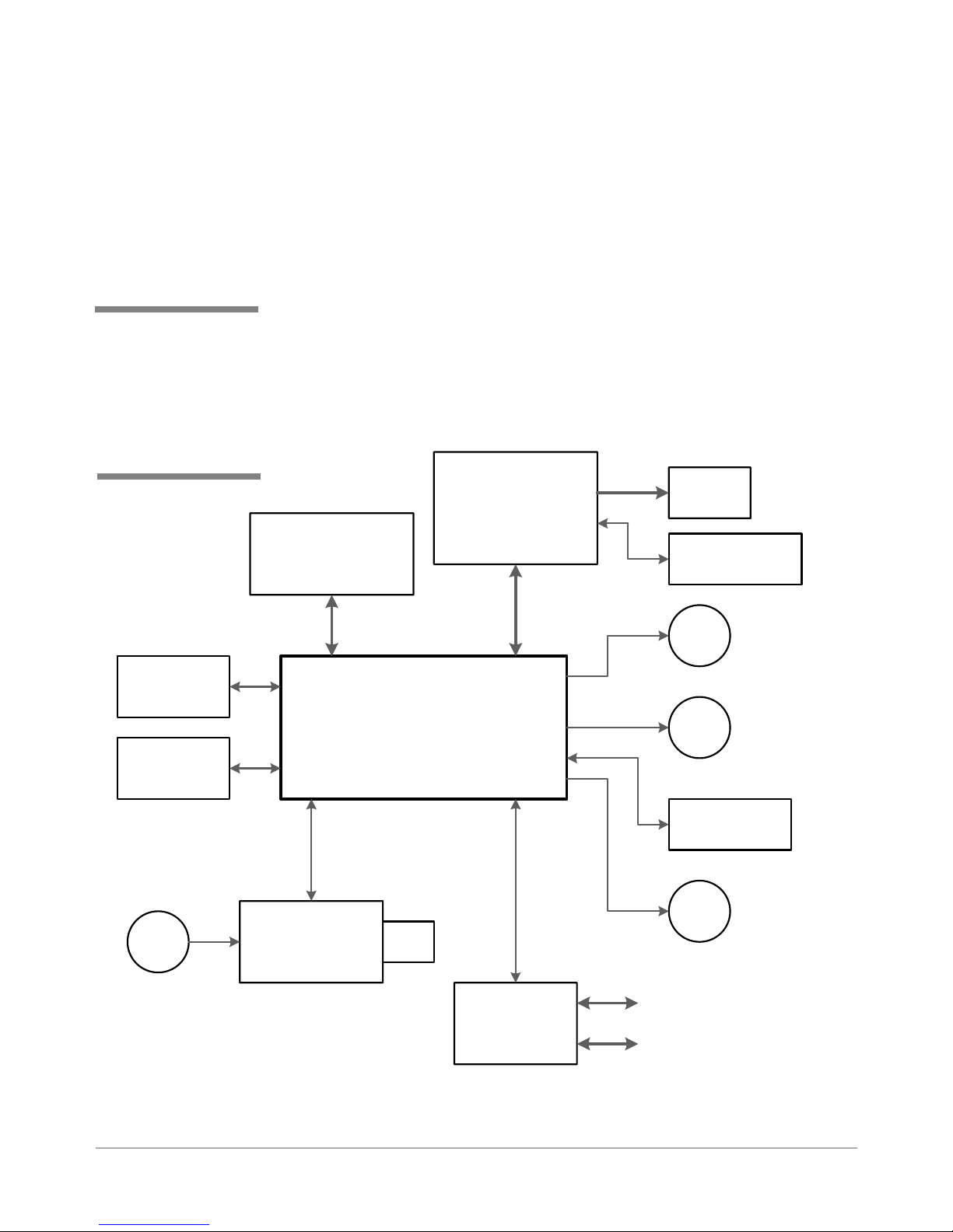
The printer system is made up of several sub-systems (see Figures 3-1 and 3-2):
• Universal Power Supply - The universal power supply has auto sensing/
switching for input voltage and intelligent shutdown capability. It ensures
proper parking of the cartridges in the maintenance station and proper
shutdown of the software. (It is the same supply used in the midrange
DM series mailing machines.)
• System Controller - The system controller is comprised of the overall op-
erating system in the firmware that controls the behavior of the system
and coordinates activities between the other sections.
• User Interface - The user interface is the LCD display, the buttons, and
the software to drive it within the firmware.
• Feeder and Transport Motion Control - The feeder and transport motion
control is responsible for feeding and positioning the envelope beneath
the printer for printing. All material motion is controlled by the transport
motor and firmware.
• Head Motion Control (Head Management) - The head motion is a combi-
nation of shuttle motion control and head management result in printing
1/2” swaths across the envelope as required. These work in conjunction
with the transport motion control for proper positioning of the printed material on the envelope.
• Communications - The communications hardware and firmware are re-
sponsible for the interface to the host PC through which print streams are
received and passed to the system controller for parsing and rendering.
Operator
Te xt
User Interface
Feeder
Transport
Motion Control
Management
Input
and
Head
LED
Power
Universal Power
Supply
Communications
USB Ethernet
Display
System
Controller
Head
Motion Control
3-2 SV61831 Rev. A DA50S/DA55S/DA70S/DA75S AddressRight™ Printers Service Manual
Busy/Error
Figure 3-1 Printer System Functional Architecture
Page 23
3.2 Printer
Architecture
Theory • 3
&RQWURO3DQHO
'LVSOD\%RDUG
:6
(PLWWHU
6HQVRU
0DLQ&RQWUROOHU%RDUG
5HFHLYHU
6HQVRU
8QLYHUVDO
$& )DQ
3RZHU6XSSO\
:6
:6
3ULQW+HDG
'ULYHU%RDUG
:6>&@
:6>%:@
3ULQW
+HDG
6KXWWOH0RWRU
(QFRGHU
0
6KXWWOH0RWRU
0
7UDQVSRUW0RWRU
6KDIW
(QFRGHU
0
0DLQWHQDQFH0RWRU
3RZHU,QSXW
Figure 3-2 Printer Block Diagram
DA50S/DA55S/DA70S/DA75S AddressRight™ Printers Service Manual
,QWHUIDFH
%RDUG
:6
/$1
86%
3-3
Page 24
3 • Theory
3.2 Printer
Architecture
/NLINE3WITCH
6ALID!DDRESS
4RANSPORT-OTOR
&EED2OLLERS
0HOTO3ENSOR
3HUTTLE-OTOR
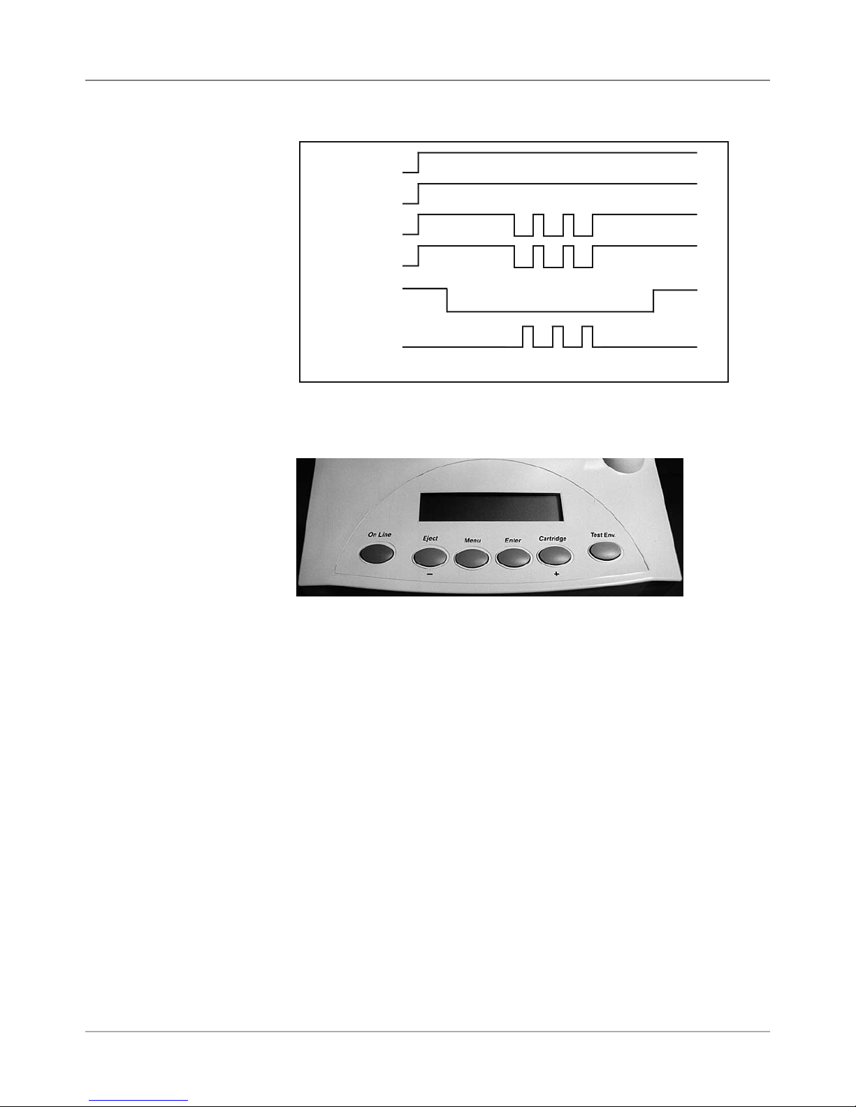
Figure 3-3 Printer Timing Diagram
1
Figure 3-4 User Interface (Control Panel) on Printer
/.
#LUTCH/.
3ENSOR"LOCKED
0RINTING/&&
2
34
5
6
1. On Line — Press to toggle between On Line (communicates with host
PC) and Off Line (no communications).
2. Eject - — Press to scroll through menu options from bottom to top. When
printer is off-line, press the minus key to eject an envelope.
3. Menu — Press to exit or enter a menu when printer is off-line.
4. Enter — While in a menu, press to enable an option.
5. Cartridge + — Press to scroll through menu options from top to bottom.
When printer is off line, press the plus key to bring the print head to the
center of its travel for cartridge replacement.
6. Test Env.— Press to print an internally generated test address.
NOTE: See Appendix A, Printer Control Panel Menus for a full explanation of
all the menu options.
3-4 SV61831 Rev. A DA50S/DA55S/DA70S/DA75S AddressRight™ Printers Service Manual
Page 25

Theory • 3
3.3 Operating
Sequence
The timing diagram (Figure 3-3) depicts the sequence of events during a
print cycle. The media to be addressed or printed upon is loaded into the
input bin. Whenever a valid address is received from the computer while the
printer is in the “on line” mode, the micro processor signals the transport motor to rotate.
The transport motor drives the main feed, intermediate and exit rollers via the
two-stage serpentine timing belts. As the main feed roller turns, it drives the
bottom piece between the “H” block separator tabs and the main feed roller.
The separator tabs retard all but the bottom piece in the stack.
The transport motor timing belt connects the upper and lower transport and
the exit rollers via the drive belt on the front plate assembly. The upper transport rollers are connected to the main feed roller by way of the timing belt on
the center plate assembly.
The main feed roller assembly (with integrated slip clutches) consists of six
rollers mounted on a shaft. Each roller has a replaceable “tire” that provides
the friction surface to drive the material through the printer. The roller assembly is driven by the main drive motor through two stages of serpentine timing
belts. The separators are designed to frictionally restrain all but the bottom
piece of media (the DA70S/DA75S has a second set of transport rollers
which help securely transport the printed media).
The feed roller moves the piece of media between the upper idler and the
upper transport rollers. The speed differential between upper / lower transport rollers and the main feed roller creates a gap between the moving pieces of media.
The lower transport rollers move the leading edge of the media into the path
of the sensor assembly.
The main feed rollers drive the leading edge of the piece into the path of the
through-beam sensor assembly. The sensor pair is mounted above the paper
guide and below the feed deck just above the shaft of the intermediate roller.
The transiting piece interrupts the infrared path between the lower (receiver)
and upper sensor (emitter/LED). The processor board sensor voltage changes, alerting the microprocessor to the location of the piece's lead edge.
The transport motor (with high-resolution encoder) continues to turn the lower transport rollers, moving the media ahead. At a predetermined measurement (bottom margin), the micro processor signals the print head shuttle DC
motor to move the print head holder assembly from the park position onto the
media surface. The encoder strip, passing through the encoder reader on the
print head drive board, keeps track of the movement of the print head. The
shuttle motor drives the print head assembly via a timing belt.
As the print head sweeps across the media, the processor signals the transport main drive DC motor to stop the feeding cycle.
DA50S/DA55S/DA70S/DA75S AddressRight™ Printers Service Manual
3-5
Page 26

3 • Theory
3.3 Operating
Sequence
The processor then sends data to the print head driver circuitry to print a
swath of information onto the media along the X axis (horizontally). After the
swath prints, the transport motor cycles on, again moving the media ahead
along the Y axis (vertically). If there is more data in the buffer, the X-Y cycle
continues until the buffer is empty.
The piece of media is then fed between the right and left hand exit idler rollers and the exit roller assembly. The lower transport and exit rollers move
the media until the trailing edge is past the infrared sensor path and ejects
the media. The sensor voltage changes and the processor registers the end
of the media. The feed rollers then push the next piece of media under the
separators for the printing cycle to begin again. The process repeats again
until all the addresses in the job are printed.
3-6 SV61831 Rev. A DA50S/DA55S/DA70S/DA75S AddressRight™ Printers Service Manual
Page 27
4 • Troubleshooting/Diagnostics
4.1 Block
Diagrams
✍
TIP: See Appendix B
- Printer Communications, for troubleshoot-
ing problems relating to
networking and printer
communications.
(PLWWHU
6HQVRU
5HFHLYHU
6HQVRU
This chapter discusses diagnostics for the DA50S/DA55S (WS51/WS56)
and DA70S/DA75S (WS71/WS76) shuttle head printers.
&RQWURO3DQHO
'LVSOD\%RDUG
:6
3ULQW+HDG
'ULYHU%RDUG
:6>&@
:6>%:@
3ULQW
+HDG
6KXWWOH0RWRU
(QFRGHU
0
6KXWWOH0RWRU
0DLQ&RQWUROOHU%RDUG
0
:6
7UDQVSRUW0RWRU
8QLYHUVDO
$& )DQ
3RZHU,QSXW
DA50S/DA55S/DA70S/DA75S AddressRight™ Printers Service Manual
3RZHU6XSSO\
:6
Figure 4-1 Shuttle Head Printer Block Diagram
,QWHUIDFH
%RDUG
:6
6KDIW
(QFRGHU
0
0DLQWHQDQFH0RWRU
/$1
86%
4-1
Page 28
4 • Troubleshooting/Diagnostics
4.1 Block
Diagrams
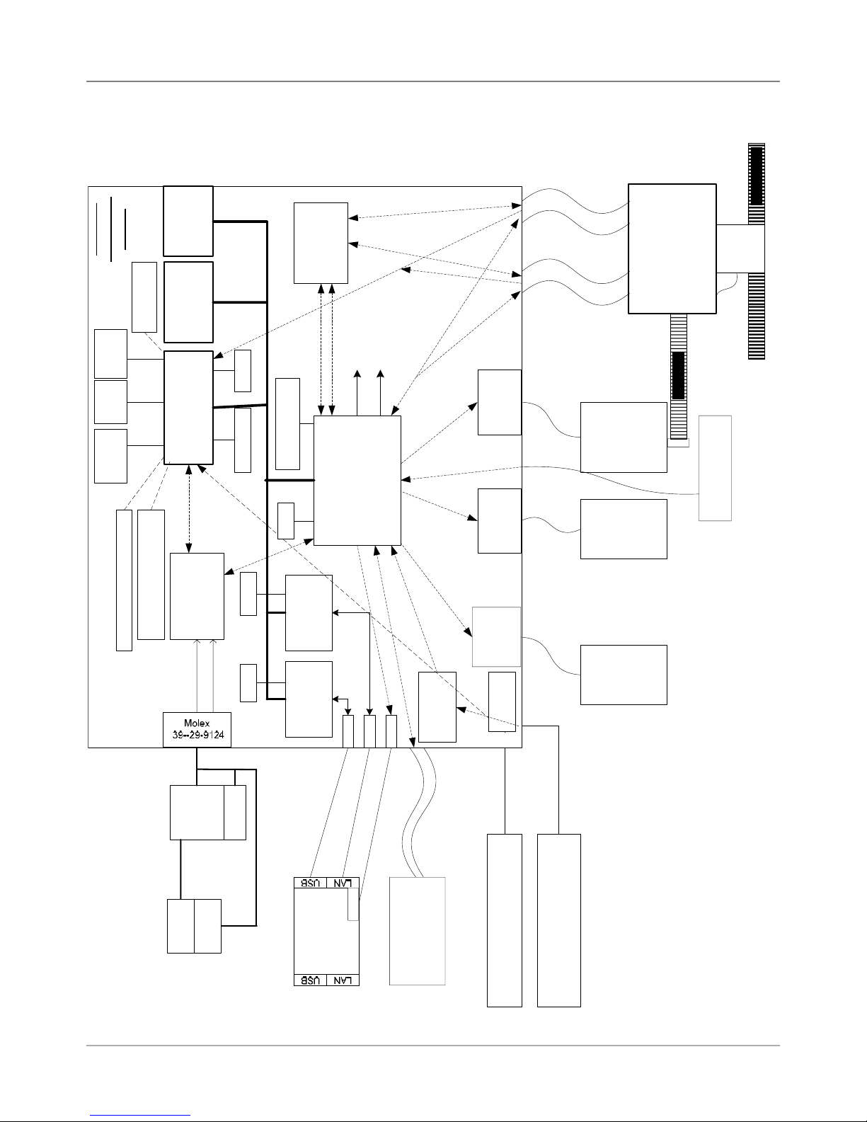
0DLQ%RDUG
:6
..
*UHHQ/('
5HG/('
&LUFXLWU\
5(6(7
6ZLWFK
',3
WHVWRQO\
56
'ULYHU
&RQILJ3LQIRU6:9HUFRQWURO
DQG%&WKUX3DSHUVHQVRU
&RQILJ3LQIRU..
0%,QWHO
0%0LFURQ
+'%3$'9
()-&
)/$6+
07/&0
6'5$0
5HQHVDV6+
&38 6+
(QFRGHU6WULS
2QEDFNRIKHDGFDUULDJH
- - - - - - -
3+'ULYHU
'$7$
ELW
'$7$
ELW
-7$*
0+]
Q7U
&
((3520
-7$*
&3+'
3+'
;&6;/34
$'&LQ
&38
,54
,5/
+%ULGJH
/
'ULYHU
'&%UXVK
:6
0RWRU
6SDUWDQ;/VHULHV
;LOLQ[)3*$
+%ULGJH
6,
'ULYHU
'&%UXVK
:6
0RWRU
3ULQW+HDG'ULYH%RDUG
(QFRGHU
6WULS
7LPLQJ%HOW
6KXWWOH
7UDQVSRUW
+3+('0-
(QFRGHUDWVKDIW
-
)XVH
&RQQHFWRU
99
,(&
5HJXODWLRQIRU
999
/$1&
(WKHUQHW
606&
8/1%
+%ULGJH
'ULYHU
9$
9$
0+]0+]
ELW'DWDELW'DWD
0LG-HW
VXSSO\
3RZHU
)$1
6ZLWFK
3RZHU
,63$
3KLOLSV
86%
86%)XQFWLRQ
(WKHUQHW
%RDUG
86%
-
/('
,QWHUIDFH
$'&6
&K$'
/$1
/('
-
-
)(0$%DFNOLJKW/&'
-
IURP.0DFKLQH
/&'%XWWRQV
8VHU,QWHUIDFH
0$;
-
(PLWWHU237(.23%
,&WR'$
5HFHLYHU237(.23
3DSHU6HQVRU
:6
6WHSSHU
0RWRU
0DLQW
%/2&.',$*5$0
..6<67(0
</HH
3DSHU6HQVRU
Figure 4-2 Shuttle Head Printer Detailed Block Diagram
4-2 SV61831 Rev. A DA50S/DA55S/DA70S/DA75S AddressRight™ Printers Service Manual
Page 29
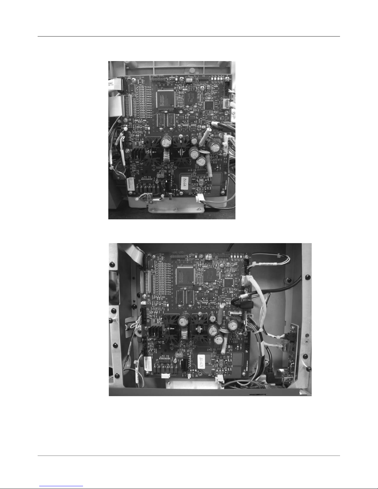
4.2 Main
Controller
Board
Diagnostics
Troubleshooting/Diagnostics • 4
Figure 4-3 Main Controller Board Mounted in DA50S/DA55S Printers
Figure 4-4 Main Controller Board Mounted in DA70S/DA75S Printers
DA50S/DA55S/DA70S/DA75S AddressRight™ Printers Service Manual
4-3
Page 30
4 • Troubleshooting/Diagnostics
4.2 Main
Controller
Board
Diagnostics
✍
TIP: Device name
is unique to each
printer’s main board.
Therefore, replacing
an existing main board
in the printer gives that
printer a new device
name.
Main Controller Board Voltage Checks
To help your troubleshooting, measure the voltages on the Main Controller
Board (with power applied) using a digital voltmeter (see tables below).
Table 4-1 Main Board Test Points With Voltage Ranges
Voltage With
Normal Range
1.5V ±5% Generated from main board TP32
3.3V ±5% Generated from main board TP31
5V ±5% Generated from main board TP54
6.5V ±5% Input from power supply TP57
12V ±5% Generated from main board (voltage occurs during
15V ±5% Generated from main board (voltage occurs when
40V ±5% Input from power supply TP55
16V ±1.5V Generated from main board (U20) for Transport Motor U20, pin 1
13V ±1.5V Generated from main board (U24) for Shuttle Motor U24, pin 9
Ground Ground for 3.3V measurement TP29
Ground Ground for 1.5V measurement TP30
Ground Ground for 12V, 15V, 40V measurement TP52
Ground Ground for 5V, 6.5V measurement TP53
Where It Comes From/Going Location
TP56
printing or when stopped)
TP56
print heads are moving into maintenance station;
maintenance motor is running)
4-4 SV61831 Rev. A DA50S/DA55S/DA70S/DA75S AddressRight™ Printers Service Manual
Page 31

Troubleshooting/Diagnostics • 4
4.2 Main
Controller
Board
Diagnostics
✍
TIP: See Appendix B
- Printer Communications, for troubleshoot-
ing problems relating to
networking and printer
communications.
Table 4-2 Main Board LED Designations
LED Color
When
Lit
CR1 Red General purpose software
CR2 Red General purpose software
CR3 Green General purpose software
CR4 Green General purpose software
CR10 Red Transport Motor Current
CR12 Green USB connection detected LED is lit when
CR13 Green Configuration Complete for
CR22 Red Paper Sensor LED lit when
Description Normal State Error State
LED is lit if either
programing (during booting
blinks once)
programing (during booting
blinks once)
programming (during booting blinks once)
programming (during booting blinks once, then three
times, then stays ON)
Limit
the FPGA (Field Programmable Gate Array - U14).
The FPGA receives its
configuration program from
the processor and must
be programmed on every
power up.
the transport mo-
tor or the shuttle
motor is running
LED is lit when
printer is printing
LED not lit LED stays lit
LED is lit LED stays off
LED is lit from
time-to-time
when printer is
printing
USB connection
is detected; blinks
when USB is
active
LED is lit (FPGA
programming is
complete)
sensor is blocked
LED stays lit
(indicates a
board/software
problem)
LED stays
lit under ALL
printer states
(indicates a
board/software
problem)
(indicates a
board/software
problem)
(indicates a
board/software
problem)
LED stays lit (indicates shuttle
motor over-current detected)
LED stays off
after connecting
a USB device
(indicates a bad
USB connection; may be
interface board
in printer, cable
or USB device
on other end)
LED stays off
(indicates a
board/software
problem)
LED not lit
when sensor is
blocked
DA50S/DA55S/DA70S/DA75S AddressRight™ Printers Service Manual
4-5
Page 32

4 • Troubleshooting/Diagnostics
4.2 Main
Controller
Board
Diagnostics
J9 (User
Interface)
J3 (Print Head
Driver Board)
J4 (Print Head
Driver Board)
J18 (Paper
Sensor, Emitter)
CR22
CR13
CR1, CR2, CR3, CR4
J22 (LED
for LAN)
J10 (LAN)
CR12
J7 (USB)
J23 (Paper
Sensor, Receiver)
J11 (Encoder
on Shaft)
J6 (Maintenance
Stepper Motor)
U24,
Pin 9
(Shuttle
Motor)
J5 (Shuttle
Motor)
Fuse (1A
Slo-Blo
250VAC)
J13 (Power)
CR10
U20, Pin 1
(Transport
Motor)
J2 (Transport Motor)
Figure 4-5 Main Controller Board With Service-Related Components Called Out
4-6 SV61831 Rev. A DA50S/DA55S/DA70S/DA75S AddressRight™ Printers Service Manual
Page 33

Troubleshooting/Diagnostics • 4
4.3
Troubleshooting
Tables
✍
TIP: See Appendix B
- Printer Communications, for troubleshoot-
ing problems relating to
networking and printer
communications.
Table 4-3 Feed/Jam Problems
Symptom Possible Cause Solution
Feed Problems
(intermittent)
Multiple feeds Brake misadjusted Check that brake gap is in
Fails to feed Feed gap incorrect Adjust “H” blocks to thickness
Motor on; main
feed roller doesn’t
turn
Input bin setup incorrect/
Feed Ramp not used
Main feed roller dirty; paper
dust (yellow residue) present
Lead/trail edge sensor dirty Clean sensor and/or run sen-
Severely worn separator tips Replace the separator tips
“H” block separators improperly set
Loose encoder Make sure encoder is attached
Lead/trail edge sensors dirty
or bad
Material out of spec
Loose setscrew on drive train Tighten screw
Drive belt (s) Check for loose or broken belt,
One way bearing bad Rotate drive belt in both direc-
Mechanical clutch broken Manually rotate Feed Rollers
Check side guide, feed angle
and position of material prop.
Adjust the media on the incline
plane of the Feed Ramp.
Check “H” block gap and if tip
of the “H” block is damaged or
misinstalled. Adjust the Wire
Form to the correct height and
to the center of the media.
Clean feed rollers with denatured alcohol
sor calibration
spec.
Adjust separators to thickness
of material
to printer properly
Blow sensors with clean with
air (replace if necessary)
of material
Minimum thickness is 0.003”;
Maximum is 0.150” (DA50/
55S) Maximum is 0.250”
(DA70/75S)
No staples, paper clips, etc., on
media
adjust spring tensioner screw
tions; check that feed roller
turns in one direction. If not,
replace one way bearing.
in both directions. Verify belts
turn only in one direction. Replace Feed Pulley.
DA50S/DA55S/DA70S/DA75S AddressRight™ Printers Service Manual
4-7
Page 34

4 • Troubleshooting/Diagnostics
4.3
Troubleshooting
Tables
✍
TIP: When working
with skew issues, you
can run the “7. Print
Head Skew” test pattern from the Service
Menu (see Appendix
A - Printer Control
Panel Menus) to
verify the problem has
been fixed (all lines in
test pattern should be
lined up).
Table 4-3 Feed/Jam Problems (continued)
Symptom Possible Cause Solution
Paper out or
Paper jam
Shuttle jam Shuttle hitting material Adjust lever so head height is
Input bin empty Refill
“H” Block separators improp-
erly adjusted
Paper jam Paper path obstructed; clear
Damaged transport shaft
encoder
Print head shaft dirty Clean shaft with alcohol and
Print head holder bushing
clogged with paper dust
Damaged flex cable connecting the print head board and
the main board
Adjust to thickness of material
jam
Replace the transport shaft
encoder
above media.
soft cotton cloth
Remove print head holder and
clean with soft cotton cloth
Replace the flex cable
4-8 SV61831 Rev. A DA50S/DA55S/DA70S/DA75S AddressRight™ Printers Service Manual
Page 35

Troubleshooting/Diagnostics • 4
4.3
Troubleshooting
Tables
Table 4-3 Feed/Jam Problems (continued)
Symptom Possible Cause Solution
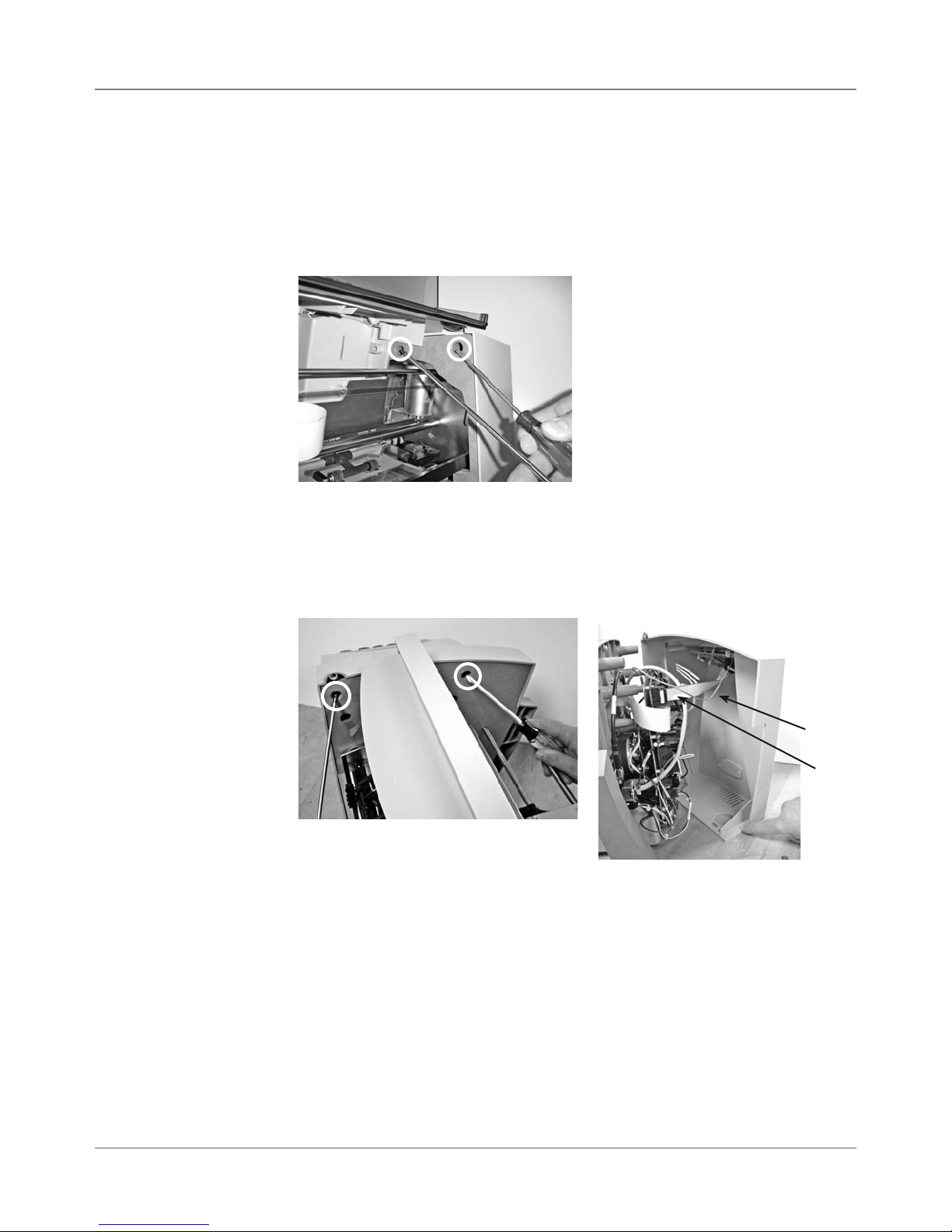
Shuttle head
doesn’t move or
moves slightly/
slowly/erractically,
but the motor
sounds like it is
trying to perform
normal operation.
Damaged flex cable connecting the print head board and
the main board
Set screws on the motor pulley driving the shuttle head
drive belt have come loose
Replace the flex cable
Tighten or replace the set
screws (two per pulley) that
are on the motor collar (see
photos below). To gain access:
1. On DA50S/DA55S, remove
non-operator access cover.
On DA70S/DA75S, open back
plexigalss cover.
2. From back of machine,
move maintenance capping
station (under motor on right)
towards front with a screwdriver or other long object.
3. Slide print head toward center of machine.
4. Locate and tighten set
screws on metal collar.
5. Return print head and capping station to original position
and reassemble cover.
Shuttlehead Motor in
DA50S/DA55S Printers
DA50S/DA55S/DA70S/DA75S AddressRight™ Printers Service Manual
Set
screws
Set
screws
Shuttlehead Motor in
DA70S/DA75S Printers
4-9
Page 36

4 • Troubleshooting/Diagnostics
4.3
Troubleshooting
Tables
Table 4-4 Print Quality Problems
Symptom Possible Cause Solution
Ink Print Quality not Sharp
Ink streaking
on Media
Non-Uniform
Print
Quality
Envelope thickness adjustment incorrect
Material out of spec Change to typical white wove bonded
Contaminated mainte-
nance station
Envelope thickness ad-
justment incorrect
Exit idler rollers dirty Clean rollers with water to remove ink
Print head needs purging Run “Purge Print Head” from Setup
The print cartridge is dirty Clean the cartridge
Print Head Holder broken Check the print head holder for
Print head holder Check that flex circuit dimples are not
Multiple print nozzles not
working
Print Head If gap appears in test pattern, replace
Adjust lever to lower print head
Clean the caps and wipe with damp
cloth or paper towel
Adjust lever to raise print head
Menu
broken pins. Replace print head
drive board if pins are broken. NOTE:
When trying to decide if print head
driver board should be replace or
not, run “Test Print Head” from Setup
Menu, replace the ink cartridge with
a new one, then run the print head
test again. If the gaps are consistent
with different ink cartridge, then the
print head driver board needs to be
replaced (when there is no physical
sign that the print head driver board
is damaged).
crushed
Run “Purge Print Head“ from Setup
Menu, then run “Test Print Head”. If
not helpful, swap ink cartridge with
known good one. If the same nozzles
are out, check the ribbon cable going
to print head cartridge (it may have
lost power to nozzles). If cable is fine,
check print head board.
print head.
4-10 SV61831 Rev. A DA50S/DA55S/DA70S/DA75S AddressRight™ Printers Service Manual
Page 37

Troubleshooting/Diagnostics • 4
4.3
Troubleshooting
Tables
✍
TIP: See Appendix B
- Printer Communications, for troubleshoot-
ing problems relating to
networking and printer
communications.
Table 4-4 Print Quality Problems (continued)
Symptom Possible Cause Solution
Print is Skewed
(Skew specification +/- 2-1/2
degrees from
bottom edge)
Address Walking (main frame
applications
only)
Gray Print Ink Jet Cartridge empty Ink supply too low, replace ink jet
No Print Ink Jet Cartridge prob-
Unwanted
BOLD type
(main frame
applications
only)
Wiper Assembly bent or
Idler Assembly set wrong
Wire frame (input bin) Adjust wire frame so it is centered
Fence Adjust fence to within 1/16” of mate-
Exit idler rollers Adjust exit idler rollers to within 1/4”
Left Justify Run left justify function in the service
Number of lines of address varies. No Form
Feed used for address
termination
Incorrect address setup Count carriage returns and line feeds
lems
Sensor dirty or bad Blow sensor clean; recalibrate sen-
Power supply voltage out
of spec
Print Head Holder broken Check for crimped or torn flex circuit
Printer Service Station
broken or unplugged
Press TEST button Standard Pitney Bowes address
Do a HEX dump of problem address
Replace wiper assembly when bent.
Level the idler or wiper assembly if
necessary.
with respect to material
rial. Check that fence is square with
re-spect to material.
of the outside edges of the material
menu
Check Line Termination CR-
CR,LF=LF. Address Termination
should be Form Feed.
of address field; should match address setup
cartridge
Purge ink jet cartridge. Clean car-
tridge with soft cotton cloth and
water.
Change to a known good cartridge
sor via Test Paper Sensor on Service
Menu on LCD (see section A.4);
replace if necessary
Check voltages on main board (see
section 4.2)
Check service station connector.
Verify that the service station moves
when printer is first switched on
should print
Examine address for ESC sequence
(1B) before the start of the line.
Turn off bolding in software and/or
turn bold selection in printer menu
OFF
DA50S/DA55S/DA70S/DA75S AddressRight™ Printers Service Manual
4-11
Page 38

4 • Troubleshooting/Diagnostics
4.3
Troubleshooting
Tables
Table 4-5 Address/Barcode Printing Problems
Symptom Possible Cause Solution
Address too high
error
Address too low Software margin; lead
Barcode (lower
right) wandering up
and down
No barcode No clear zone (5/8”
Software margin; lead
edge sensor “seeing
through” paper
Paper size used
doesn’t match the
layout size
Sensor is dirty or bad Blow sensor clean; recalibrate
The sensor may
misread if during the
printing process the
envelope trail edge
covers the paper sensor half-way.
edge sensor “seeing
through” paper
Paper size used
doesn’t match the
layout size
Sensor is dirty or bad Blow sensor clean; recalibrate
Belt tension not set
properly
minimum distance)
Invalid ZIP Code Check ZIP Code
Top line of address is above edge
of material. Move address location
down. Adjust lead edge sensor.
Adjust the layout size in the control
panel menu
sensor via Test Paper Sensor on
Service Menu on LCD (see section
A.4); replace if necessary
By printing something when the
paper sensor is half-covered, it
causes the sensor reading to flicker
during the process. Move the text
or graphics that is close to the trail
edge of the envelope up or down
slightly so that the sensor is either
covered or uncovered, not half covered when the content is printed.
The address is below the bottom
edge of the material. Increase the
bottom edge margin. Adjust lead
edge sensor.
Adjust the layout size in the control
panel menu
sensor via Test Paper Sensor on
Service Menu on LCD (see section
A.4); replace if necessary
Check main drive belt tension adjustment (see Adjustments section)
5/8” required between last line of
address and bottom edge of material
4-12 SV61831 Rev. A DA50S/DA55S/DA70S/DA75S AddressRight™ Printers Service Manual
Page 39
Troubleshooting/Diagnostics • 4
4.3
Troubleshooting
Tables
✍
TIP: Device name
is unique to each
printer’s main board.
Therefore, replacing
an existing main board
in the printer gives that
printer a new device
name.
Table 4-6 Miscellaneous Problems
Symptom Possible Cause Solution
LCD display shows
solid line of erroneous
characters
Nothing happens
when power is
switched on
Power supply problem Check J13 (provides power
to board from power supply).
Replace Power Supply if
necessary.
Bad Main Board Replace main board
Cable loose at the display
or motherboard
Bad LCD display board Replace the display board
No power to AC inlet of
printer
J13 on Main Board discon-
nected
Fuse is blown on Main
Board
Fuse blown in Power Supply
Check P9 cable to LCD dis-
play is secured at both ends
Check power cord and AC
outlet to which it is plugged in
Connect J13 (provides power
to board from power supply)
Replace fuse (Slo Blo 1A
250V) on the mainboard right
next to J13
Replace power supply (no
service replaceable parts
inside)
DA50S/DA55S/DA70S/DA75S AddressRight™ Printers Service Manual
4-13
Page 40

4 • Troubleshooting/Diagnostics
4.4 Printer
Error Codes
✍
TIP: Error codes are
internal to the firmware
and not displayed on
the LCD. Only the textual description of the
error is displayed.
✍
TIP: The printer firmware
errors are categorized
into different system error types:
• Unknown error (0)
• Paper transport error (1)
• Shuttle error (2)
• EEPROM failure (3)
• Out of memory error (4)
• Color ink out (5)
• Black ink out (6)
Table 4-7 Printer Error Codes
Error Text System
Error
Unknown Error 0 Restart the printer
Paper Jam 1 1 Clear the jam and put
Out of Paper 1 2 Load the feeder with
Address too
High
Paper Sensor
Failure
Sensor Blocked 1 6 Sensor is dirty or media
Sensor Dirt 1 7 Sensor is dirty
Shuttle Error 2 0 Make sure shuttle can
Shuttle Jam 2 1 Clear jam and put the
Over Current 2 2 Clear the jam and put
EEPROM
Failure
File Print Error Not being displayed
Eject Error Not being displayed
Out of Memory 4 Restart the printer
No Color Ink
(Color printer
only)
No Black Ink 6 Com-
System Shutdown
1 3 Load the bigger media
1 5 Clean the sensor and
3 Put the printer back on-
5 Com-
Error
Code
posite
posite
N/A Not an error
Possible Resolution Comments
the printer back online
paper and put the printer
back online
This is due to the
size
run sensor calibration
is blocking the sensor.
Clear the sensor and put
the printer back online
move freely by hand
and put the printer back
online
printer back online
the printer back online
line to see if printer continues to run properly. If
not, EEPROM hardware
problem. Service call
Change the ink cartridge
Change the black ink
image printed on
paper is bigger than
media it is printed
on
Detected as shuttle
jam
currently
currently
4-14 SV61831 Rev. A DA50S/DA55S/DA70S/DA75S AddressRight™ Printers Service Manual
Page 41
Troubleshooting/Diagnostics • 4
4.5 Print
Samples for
Troubleshooting
The print samples below are provided to help troubleshoot printing problems
you may encounter.
Table 4-8 Sample Prints
Sample Print What It Indicates
Good printing
Poor printing due
to low ink (replace
ink cartridge)
Good test print
Smudging (need
to purge print
head)
Return Address
A. Skew
B. Misfiring head
(missing points,
do purge print
head)
All 3 versions of FIM
Barcode (USPS)
Figure 4-6 Sample Envelope Printed with a Variety of Options
DA50S/DA55S/DA70S/DA75S AddressRight™ Printers Service Manual
Postnet Barcode (USPS)
4-15
Page 42

4 • Troubleshooting/Diagnostics
4-16 SV61831 Rev. A DA50S/DA55S/DA70S/DA75S AddressRight™ Printers Service Manual
Page 43

5 • Removal & Replacement
5.1 List of
Procedures
This chapter contains parts removal instructions and is divided into two sections; one for the DA50S/DA55S and one for the DA70S/DA75S printers.
Tools Required
• Ball end square drives. Sizes used:
#0 for 4-40 screws
#1 for 6-32 screws
#2 for 8-32 screws
NOTE: Phillips head screwdrivers of the same size work but not as well if
you are at an angle.
• Allen wrenches (imperial standard sizes). NOTE: The extra small encoder Allen (.050 inch) is taped inside each printer.
DA50S/DA55S (WS51/WS56) Parts Removal
5.2 Covers ...................................................................................... 5-2
5.3 Display/Keyboard ..................................................................... 5-3
5.4 Main Processor Board/Grounding Sheet Assembly ................. 5-3
5.5 USB/Ethernet Input Board ........................................................ 5-4
5.6 Power Supply ........................................................................... 5-5
5.7 Paper Transport Motor/Belt ...................................................... 5-7
5.8 Sensor ...................................................................................... 5-9
5.9 Feed Roller Assembly ..............................................................5-11
5.10 Encoder and Operator Side Drive Belt ................................. 5-13
DA70S/DA75S (WS71/WS76) Parts Removal
5.11 Covers .................................................................................. 5-15
5.12 Display/Keyboard ................................................................. 5-17
5.13 Main Processor Board/Grounding Sheet Assem. ................. 5-17
5.14 USB/Ethernet Input Board .................................................... 5-18
5.15 Power Supply ....................................................................... 5-18
5.16 Feed Roller Assembly............................................................ 5-19
5.17 Motor Drive Belts and Main Motor ........................................ 5-21
5.18 Exit Roller ............................................................................. 5-23
5.19 Sensor .................................................................................. 5-23
5.20 Shuttle Head Motor, Print Head, Shuttle Drive ..................... 5-24
5.21 H-Block Tip ........................................................................... 5-25
DA50S/DA55S/DA70S/DA75S AddressRight™ Printers Service Manual
5-1
Page 44
5 • Removal & Replacement
DA50S/DA55S (WS51/WS56) Parts Removal
5.2 Covers
1. Remove chrome paper stand and metal side guide.
2. Lift up smoked plastic output cover. Unfasten two phillips screws from
non-operator side cover (see photo below). Smoked output cover comes
off with side cover. Lift up printer slightly to completely remove side cover
(one printer foot is captured by the cover).
3. Unfasten two phillips screws from operator side cover (see left photo below). Lift up printer slightly to completely remove side cover (two printer
feet are captured by the cover). Unfasten display/keyboard cable (gray
P9) and the green grounding cable (see right photo below) that attaches to
board mounted on cover.
Green
Ground
P9
5-2 SV61831 Rev. A DA50S/DA55S/DA70S/DA75S AddressRight™ Printers Service Manual
Page 45

Removal & Replacement • 5
DA50S/DA55S (WS51/WS56) Parts Removal
5.3 Display/
Keyboard
5.4 Main
Processor
Board/
Grounding
Sheet
Assembly
1. Unfasten operator side cover (two phillips screws). Lift up printer slightly
to completely remove cover (two printer feet are captured by the cover)
2. From behind cover, unfasten display/keyboard cable (gray P9) and the
green grounding cable (see photo below).
3. Carefully peel back display overlay (from corner) on front of display.
4. Remove three phillips head screws (circled below) from underneath and
remove board from cover.
Display/Keyboard Board
(screw locations in circles)
1. Remove operator side cover (see section 5.2).
2. Remove all cables. Starting clockwise from top right: P22, P10 (LAN),
P7 (USB), P13, P2 (red/white motor cable), P5, P6, P11, P23, P18, P3
(white ribbon cable), P4 (2nd white ribbon cable if color printer), and P9.
3. Remove 11 phlllips screws (circled in left photo below) holding board to
shield and remove board.
4. Remove grounding strap from bottom left corner and three bottom
screws (circled in right photo below) to remove grounding sheet.
DA50S/DA55S/DA70S/DA75S AddressRight™ Printers Service Manual
Main Processor Board
(screw locations in circles)
Grounding Sheet Under
Main Processor Board
(screw locations in circles)
5-3
Page 46

5 • Removal & Replacement
DA50S/DA55S (WS51/WS56) Parts Removal
5.5 USB/
Ethernet Input
Board
1. Remove operator side cover (see section 5.2).
2. Remove P3, P4, P5 from USB/Ethernet board.
3. Remove two phillips screws fastening board to chassis.
USB/Ethernet Board
(screw locations in circles)
5-4 SV61831 Rev. A DA50S/DA55S/DA70S/DA75S AddressRight™ Printers Service Manual
Page 47

Removal & Replacement • 5
DA50S/DA55S (WS51/WS56) Parts Removal
5.6 Power
Supply
1. Remove operator and non-operator side covers (see section 5.2).
2. Remove main processor board/grounding sheet assembly (see section
5.43A).
3. On non-operator side, remove P18, P5, and P6 junction connectors.
4. Remove ground strap (furthest on the right with black sleeve), see photo.
Ground
Strap
5. Remove three main power cables to AC inlet. Use screwdriver or needle
nose pliers to pry off each (see photo below).
Using Screwdriver
to Pry Cables from
Spade Lugs (3)
Spade Lug
6. Remove two phillips screws holding blue side chassis to bottom gray tray
(see photo below). Do for both sides of machine (four screws total).
Side Chassis Attachment
to Gray Tray (screw locations in circles)
DA50S/DA55S/DA70S/DA75S AddressRight™ Printers Service Manual
5-5
Page 48

5 • Removal & Replacement
DA50S/DA55S (WS51/WS56) Parts Removal
5.6 Power
Supply
(continued)
7. Lift and remove top chassis assembly from bottom gray tray.(photo)
Top Chassis
Bottom Tray
8. Remove the four screws holding captive the power supply feet.
Close-up of One
Screw Holding
Power Supply
Feet (in circle)
9. Remove power supply assembly (includes fan, housing and cables).
Power Supply
Assembly
5-6 SV61831 Rev. A DA50S/DA55S/DA70S/DA75S AddressRight™ Printers Service Manual
Page 49

Removal & Replacement • 5
DA50S/DA55S (WS51/WS56) Parts Removal
5.7 Paper
Transport
Motor/Belt
1. Remove operator and non-operator side covers (see section 5.2).
2. Remove main processor board/grounding sheet assembly (see section
5.4).
3. On non-operator side, remove P18, P5, and P6 junction connectors.
4. Remove ground strap (furthest on the right with black sleeve), see photo.
Ground
Strap
5. Remove three main power cables to AC inlet. Use screwdriver or needle
nose pliers to pry off from each spade lug (see photo below).
Using Screwdriver
to Pry Cables from
Spade Lugs (3)
Spade Lug
6. Remove two phillips screws holding blue side chassis to bottom gray tray
(see photo below). Do for both sides of machine (four screws total).
Side Chassis Attachment
to Gray Tray (screw locations in circles)
DA50S/DA55S/DA70S/DA75S AddressRight™ Printers Service Manual
5-7
Page 50
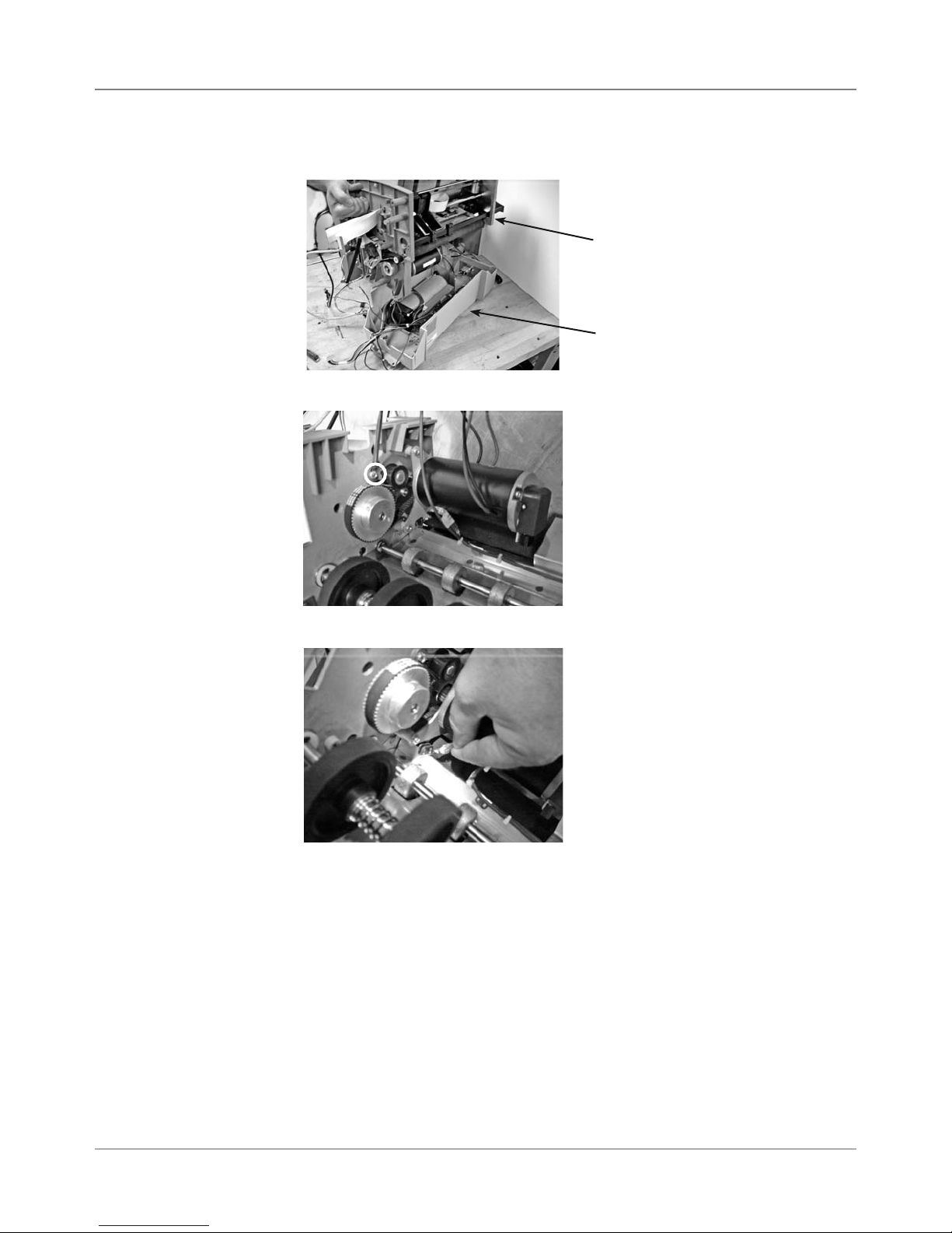
5 • Removal & Replacement
DA50S/DA55S (WS51/WS56) Parts Removal
5.7 Paper
Transport
Motor/Belt
(continued)
7. Lift and remove top chassis assembly from bottom gray tray.
Top Chassis
Bottom Tray
8. Loosen main drive belt by idler pulley screw (circled).
9. Remove ground strap from motor (force fit).
10. Remove three screws that hold motor to side frame and remove motor.
11. Remove belt.
5-8 SV61831 Rev. A DA50S/DA55S/DA70S/DA75S AddressRight™ Printers Service Manual
Page 51
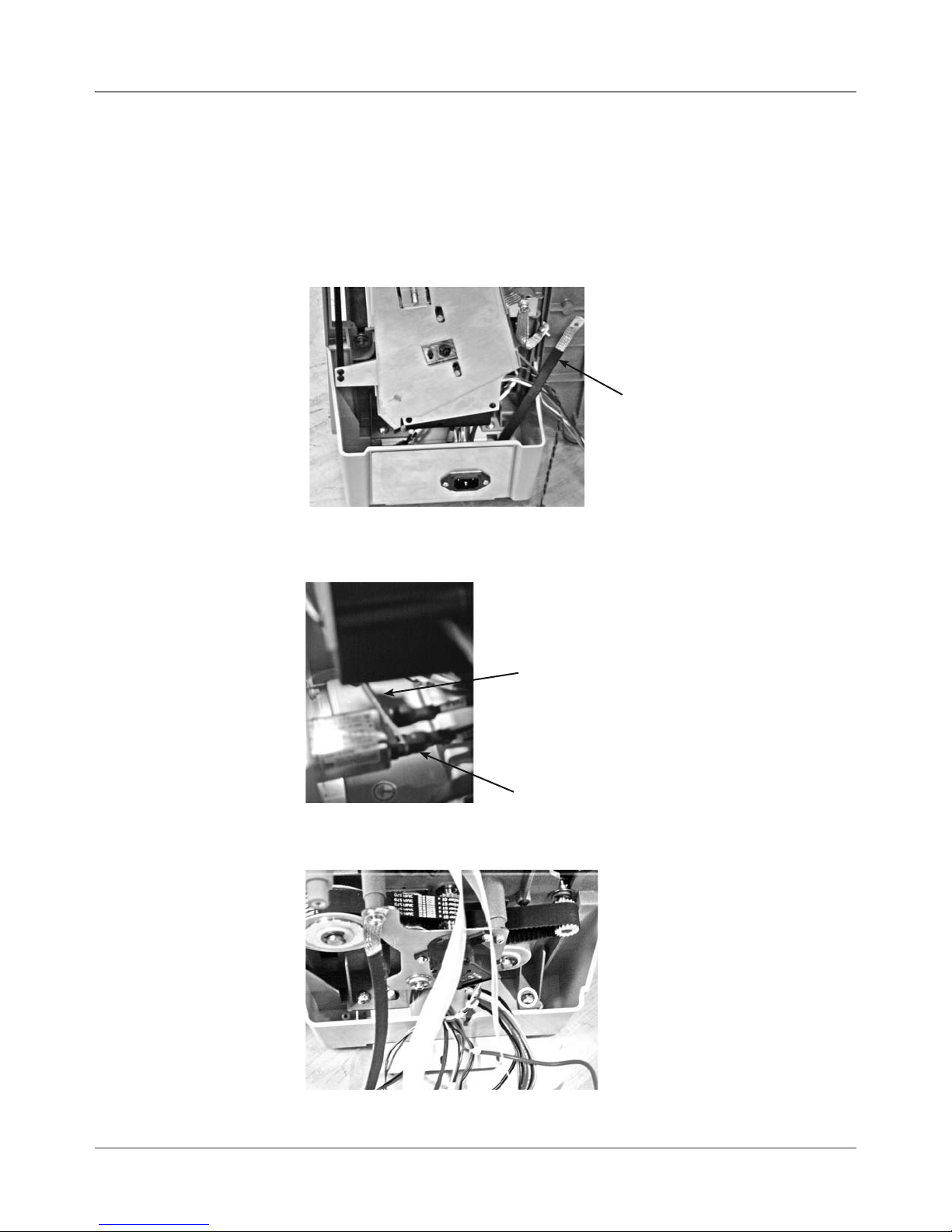
Removal & Replacement • 5
DA50S/DA55S (WS51/WS56) Parts Removal
5.8 Sensor
1. Remove operator and non-operator side covers (see section 5.2).
2. Remove main processor board/grounding sheet assembly (see section
5.4).
3. On non-operator side, remove P18, P5, and P6 junction connectors.
4. Remove ground strap (furthest on the right with black sleeve), see photo.
Ground
Strap
5. Remove three main power cables to AC inlet. Use screwdriver or needle
nose pliers to pry off each (see photo below).
Using Screwdriver
to Pry Cables from
Spade Lugs (3)
Spade Lug
6. Remove two phillips screws holding blue side chassis to bottom gray tray
(see photo below). Do for both sides of machine (four screws total).
Side Chassis Attachment
to Gray Tray (screw locations in circles)
DA50S/DA55S/DA70S/DA75S AddressRight™ Printers Service Manual
5-9
Page 52

5 • Removal & Replacement
DA50S/DA55S (WS51/WS56) Parts Removal
5.8 Sensor
(continued)
7. Lift and remove top chassis assembly from bottom gray tray.
Top Chassis
Bottom Tray
8. Remove three tie-wraps (circled) holding sensor harness (P23).
9. Press sensor up and off holding tab (circled).
5-10 SV61831 Rev. A DA50S/DA55S/DA70S/DA75S AddressRight™ Printers Service Manual
Page 53

Removal & Replacement • 5
DA50S/DA55S (WS51/WS56) Parts Removal
5.9 Feed
Roller
Assembly
1. Remove operator and non-operator side covers (see section 5.2).
2. Remove main processor board/grounding sheet assembly (see section
5.4).
3. Remove shield covering u-channel on non-operator side. Remove four
screws for u-channel itself (circled in photo below).
4. Remove allen screws on black exit roller support shaft (circled in photo
below). Remove the black exit roller support shaft and slide u-channel
out of machine.
5. On non-operator side, remove P18, P5, and P6 junction connectors.
6. Remove operator side drive belt off of feed roller assembly pulley. Loosen idler pulley (pointed to by screwdriver below). Push idler pulley to
compress the spring. Retighten idler pulley.
DA50S/DA55S/DA70S/DA75S AddressRight™ Printers Service Manual
Idler Pulley
5-11
Page 54
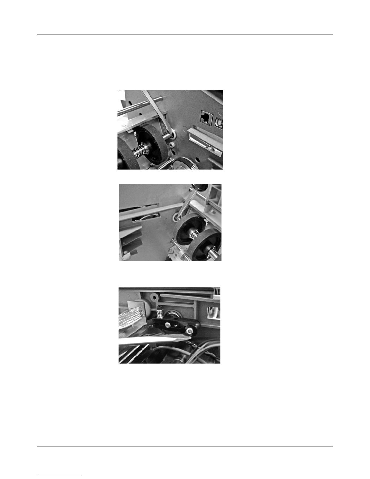
5 • Removal & Replacement
DA50S/DA55S (WS51/WS56) Parts Removal
5.9 Feed
Roller
Assembly
(continued)
7. Slide belt off pulley.
8. Remove e-clip and nylon washer (pointed to by screwdriver below). Remove pulley from shaft. Remove nylon washer and other metal washer.
9. Remove e-clip on both sides of shaft (pointed to by screwdriver below).
10. On non-operator side, remove black brake (allen and phillips screw),
pointed to by screwdriver below.
11. Remove four screws holding (two on each side) holding H block assembly to chassis.
12. Remove three phillips and one allen head screws holding deck to chassis. Remove grounding strap. Remove deck.
13. Separate blue side frames and remove feed roller assembly.
5-12 SV61831 Rev. A DA50S/DA55S/DA70S/DA75S AddressRight™ Printers Service Manual
Page 55

Removal & Replacement • 5
DA50S/DA55S (WS51/WS56) Parts Removal
5.10 Encoder
and Operator
Side Drive Belt
1. Remove operator side cover (see section 5.2).
2. Remove main processor board/grounding sheet assembly (see section
5.4).
3. Remove allen wrench taped to operator side chassis.
Allen Wrench for Encoder
Taped to Inside Chassis
4. Turn encoder disc lock screw counter-clockwise from two-dot stop to
one-dot stop. The screw recesses and exposes the hole where the allen
wrench goes in on top.
5. Rotate the drive main drive belt which rotates the encoder. This allows
you to find the allen head screw that tightens the encorder on the shaft.
DA50S/DA55S/DA70S/DA75S AddressRight™ Printers Service Manual
Turning Encoder Disc
Lock Screw to Allow
Loosening of Encoder
Main Drive Belt
5-13
Page 56
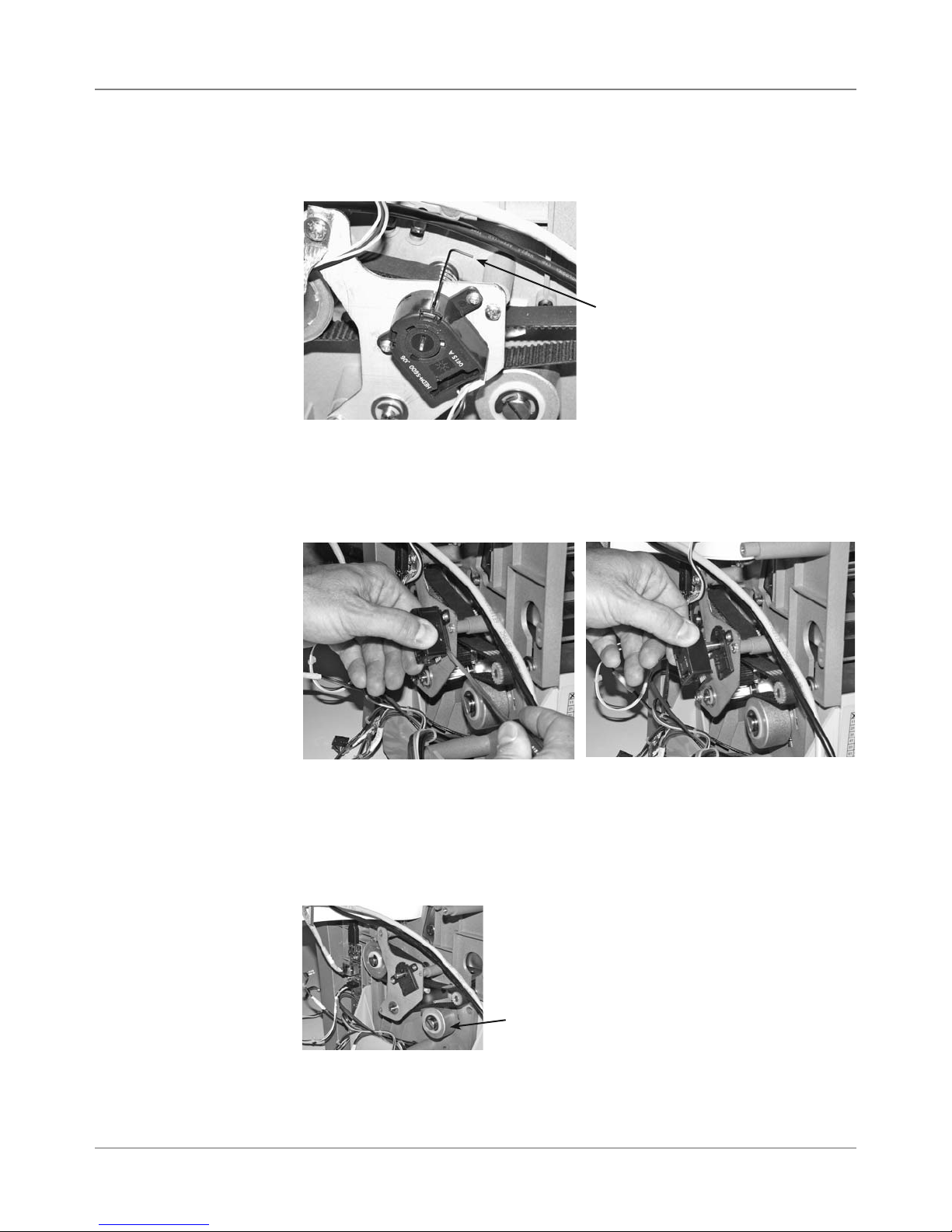
5 • Removal & Replacement
DA50S/DA55S (WS51/WS56) Parts Removal
5.10 Encoder
and Operator
Side Drive Belt
(continued)
6. Once you find the allen head, use the enclosed wrench to loosen the allen screw a turn or two (just to loosen, NOT to remove the encoder).
Allen Wrench
7. Unplug encoder harness ENC.
8. Use small screwdriver to separate main body cover of encoder from
encoder mounting backing. Do not remove backing plate because it is
placed by the factory in a precise position.
Carefully Prying Off Encoder Body with Small Screwdriver
NOTE: When replacing, place (snap on) new encoder on mounting back-
ing. Tighten allen screw with wrench, but do NOT overtighten. Turn encoder disc lock screw clockwise from one-dot stop to two-dot stop to lock.
9. Release the belt tension by loosening the idler pulley, then retighten.
10. Remove three screws, e-clip, and nylon washers from triangular metal
mounting plate. Remove plate.
11. Walk belt off.
5-14 SV61831 Rev. A DA50S/DA55S/DA70S/DA75S AddressRight™ Printers Service Manual
Idler Pulley
Page 57

Removal & Replacement • 5
DA70S/DA75S (WS71/WS76) Parts Removal
5.11 Covers
1. Slide off side guide (metal) and unscrew threaded knob for paper stand
(chrome). Slide chrome stand to right and lift out.
2. Remove four allen screws (5/64”) on rear and remove smoked output
cover. NOTE: Hinges for smoked cover are spring-loaded, so be careful
during removal and replacement.
3. Remove four phillips head screws on non-operator side cover (note locking tabs on bottom).
Non-Operator
Side Cover
Removed With
Locking Tabs
4. Remove three phillips screws on operator side cover (one on either side,
one underneath). Note the metal locating hooks behind cover.
After Removal
of Operator
Side Bottom
Cover
5. Remove three phillips screws holding control panel cover (two on one
side, one on the other).
6. Remove gray P2 and green ground cable (uses 9/64” allen) going to keyboard/control board and remove cover.
After Removal
of Operator
Control Panel
Cover
DA50S/DA55S/DA70S/DA75S AddressRight™ Printers Service Manual
5-15
Page 58

5 • Removal & Replacement
DA70S/DA75S (WS71/WS76) Parts Removal
5.11 Covers
(continued)
7. Remove two screws on top and two (5/64”) on bottom for lower input
cover.
After Removal
of Bottom Lower
Input Cover
8 Tip printer on its side and remove six allen screws (5/64”) for bottom
hatch cover.
After Removal
of Bottom
Hatch Cover
9. Remove six phillips screws for lower output cover (two on each side, two
on face). Remove one allen head, recessed on side.
After Removal
of Lower Output
Cover
10. Remove remaining allen head on operator side, then two allen heads on
non-operator side to remove top cover, output side.
5-16 SV61831 Rev. A DA50S/DA55S/DA70S/DA75S AddressRight™ Printers Service Manual
Page 59

Removal & Replacement • 5
DA70S/DA75S (WS71/WS76) Parts Removal
5.12 Display/
Keyboard
5.13 Main
Processor
Board/
Grounding
Sheet
Assembly
1. Remove three phillips screws holding control panel cover (two on one
side, one on the other).
2. Remove gray P2 and green ground cable (uses 9/64” allen) going to keyboard/control board.
3. Carefully peal back display overlay (from corner).
4. Remove three phillips head screws from underneath and remove board
from cover.
Display/Keyboard Board
(screw locations in circles)
1. Remove non-operator side cover.
2. Remove all cables. Starting clockwise from top right: P22, P10 (LAN),
P7 (USB), P13, P2 (red/white motor cable), P5, P6, P11, P23, P18, P3
(white ribbon cable), P4 (2nd white ribbon cable if color printer), and P9.
3. Remove three screws (see photo below, circled) going through board and
grounding plate.
4. Remove the nine additional screws to remove board from grounding
plate.
DA50S/DA55S/DA70S/DA75S AddressRight™ Printers Service Manual
5-17
Page 60

5 • Removal & Replacement
DA70S/DA75S (WS71/WS76) Parts Removal
5.14 USB/
Ethernet
Input Board
5.15 Power
Supply
1. Remove non-operator side cover.
2. Remove P5, Ethernet P10, USB P7.
3. Remove two phillips screws.
USB/Ethernet Board
(screw locations in circles)
1. Remove input lower cover.
2. Remove non-operator side cover.
3. Remove three main power cables to AC inlet. Use screwdriver or needle
nose pliers to pry off each (see photo below).
4. Remove four cables from spades on power switch next to AC inlet (see
photo below).
Cables on Spade Lugs
(Four) for Power Switch
Using Screwdriver to Pry Cables
from AC Spade Lugs (Three)
5. Unfasten P13 from main board.
6. Remove the four feet screws on
bottom of power supply (use stubby or 90 degree phillips).
7. Remove power supply (include fan,
housing and cables). See photo at
right.
Power Supply Removed
5-18 SV61831 Rev. A DA50S/DA55S/DA70S/DA75S AddressRight™ Printers Service Manual
Page 61

Removal & Replacement • 5
DA70S/DA75S (WS71/WS76) Parts Removal
5.16 Feed
Roller
Assembly
1. Remove lower operator side (see section 5.11).
2. Remove non-operator side cover (see section 5.11).
3. Remove main processor board assembly (see section 5.13).
4. On operator side, remove brake assembly (circled in photo below) by
loosening two allen screws and removing one.
Brake Assembly Removed
5. On operator side, remove two allen screws for feed roller shaft bearing
(circled in photo). Remove bearing. Shaft and black rollers drop down.
Dropped
Rollers
Feed
Roller
Shaft
6. On non-operator side, loosen and remove feed belt drive idler (circled in
photo). Then remove feed roller drive belt.
Feed Roller Drive Belt
DA50S/DA55S/DA70S/DA75S AddressRight™ Printers Service Manual
5-19
Page 62

5 • Removal & Replacement
DA70S/DA75S (WS71/WS76) Parts Removal
5.16 Feed
Roller
Assembly
(continued)
7. On non-operator side, remove two allen and two phillips screws for metal
bracket holding feed roll drive belt.
Allen
Phillips
8. On non-operator side, pull out feed roller assembly through access hole.
5-20 SV61831 Rev. A DA50S/DA55S/DA70S/DA75S AddressRight™ Printers Service Manual
Page 63

Removal & Replacement • 5
DA70S/DA75S (WS71/WS76) Parts Removal
5.17 Motor
Drive Belts
and Main
Motor
1. Remove operator lower side cover (see section 5.11).
2. Loosen idler and rotate to relieve pressure (tighten to keep belt loose).
3. Remove motor drive belt.
Motor Drive Belt Plate
4. Remove large metal pulley (see photo below) and nylon washer used for
motor drive belt (5/16” allen used). Remove motor drive belt.
Main Drive Idler
Large Metal Pulley
and Motor Drive Belt
5. Remove six phillips screws holding motor drive belt plate (see photo below).
Motor Drive
Plate
Motor Mount Screws
6. Remove four allen screws (circled in photo below) holding motor to motor
drive plate.
7. Remove input side lower cover.
8. Back out motor through opening in input side.
DA50S/DA55S/DA70S/DA75S AddressRight™ Printers Service Manual
5-21
Page 64

5 • Removal & Replacement
DA70S/DA75S (WS71/WS76) Parts Removal
5.17 Motor
Drive Belts
and Main
Motor
(continued)
9. Disconnect encoder harness (ENC) at motor and J2 from main board and
remove main motor.
10. Remove e-clip and wave washer from inside side frame holding the jack
shaft to frame.
11. Unplug cable to encoder (ENC).
Main Drive Belt
Encoder Cable
12. Remove main drive belt (see photo above).
5-22 SV61831 Rev. A DA50S/DA55S/DA70S/DA75S AddressRight™ Printers Service Manual
Page 65

Removal & Replacement • 5
DA70S/DA75S (WS71/WS76) Parts Removal
5.18 Exit
Roller
1. Remove operator lower side cover (see section 5.11).
2. Remove lower output cover (see section 5.11).
3. Release belt pressure on main drive belt by loosening the idler. Unattach
belt.
Side Frame Screws
Main Drive Idler
4. Remove operator side frame screws (five allens and two phillips, see
above).
5. Spread side frames apart and remove exit roller from non-operator side
frame. Note washer on bearing.
Removal of
Exit Roller
5.19 Sensor
DA50S/DA55S/DA70S/DA75S AddressRight™ Printers Service Manual
1. Tip machine on side and remove bottom hatch cover.
2. Slide sensor (circled in photo below) off holding tab.
3. Remove J23 harness to Main Board.
5-23
Page 66
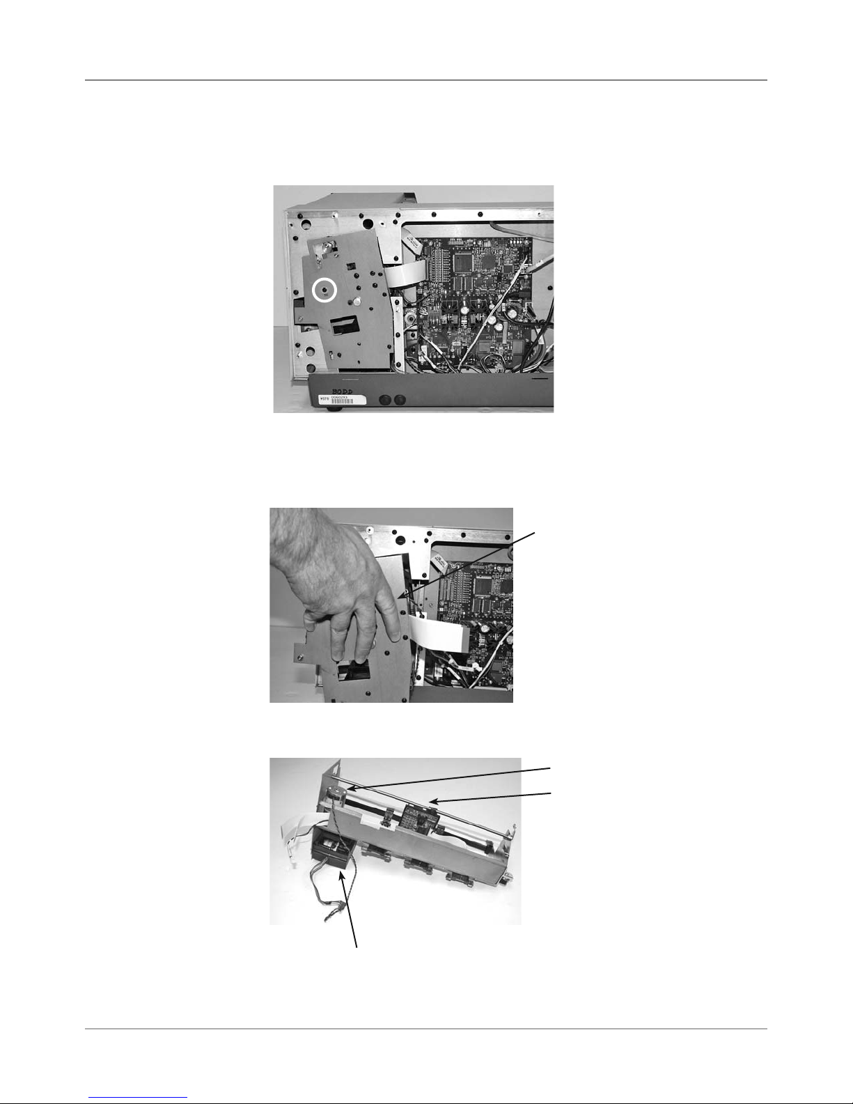
5 • Removal & Replacement
DA70S/DA75S (WS71/WS76) Parts Removal
5.20 Shuttle
Head Motor,
Print Head
Board,
Shuttle Head
Drive Belt
1. Remove non-operator side cover (see section 5.11).
2. Remove phillips screw with nylon washer (circled below) holding u-channel.
3. Unfasten J3 and J4 flat gray cables, J18 sensor harness, J5 (motor harness), and J6 from main board.
4. Slide out u-channel assembly from non-operator side access.
U-Channel Assembly
5. Remove print head, motor, and print head board as necessary from uchannel assembly.
5-24 SV61831 Rev. A DA50S/DA55S/DA70S/DA75S AddressRight™ Printers Service Manual
Print Head Motor
Print Head Board
Print Head
Page 67
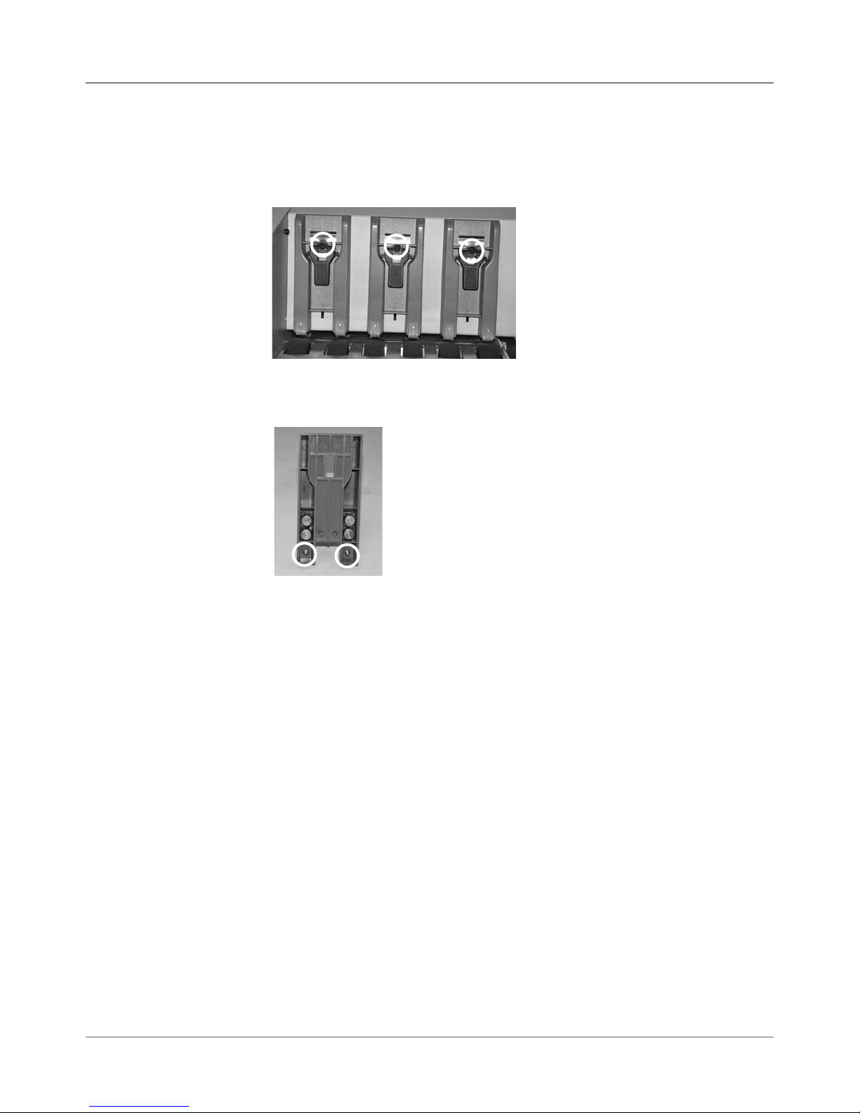
Removal & Replacement • 5
DA70S/DA75S (WS71/WS76) Parts Removal
5.21 H-Block
Tip
1. Slide metal guide and paper stand away from H-block.
2. Remove allen screw (see photo below, circled) holding H-block and remove H-block.
3. On backside of H-block, remove phillip screws (see photo below, circled)
for each tip.
DA50S/DA55S/DA70S/DA75S AddressRight™ Printers Service Manual
5-25
Page 68

5 • Removal & Replacement
DA70S/DA75S (WS71/WS76) Parts Removal
5-26 SV61831 Rev. A DA50S/DA55S/DA70S/DA75S AddressRight™ Printers Service Manual
Page 69

6 • Adjustments
6.1 List of
Adjustments
This chapter discusses adjustments for the DA50S/DA55S (WS51/WS56)
and DA70S/DA75S (WS71/WS76) shuttle head printers.
Adjustments for All Models
6.2 LCD Display .............................................................................. 6-2
6.3 Paper Sensor Test and Calibration ........................................... 6-2
DA50S/DA55S (WS51/WS56) Adjustments
6.4 Main Brake ............................................................................... 6-3
6.5 Print head Clearance ................................................................. 6-5
6.6 Adjusting Exit Roller Idler Assembly .......................................... 6-6
6.7 Print head Drive Belt ................................................................. 6-7
6.8 Main Drive Belt .......................................................................... 6-8
6.9 Adjusting Service Station Assembly .......................................... 6-9
DA70S/DA75S (WS71/WS76) Adjustments
6.10 Main Brake ............................................................................ 6-10
6.11 Print Head Drive Belt ............................................................. 6-10
6.12 Timing Belt .............................................................................6-11
6.13 Main Drive Belt .......................................................................6-11
6.14 Print Head Home Position ..................................................... 6-12
DA50S/DA55S/DA70S/DA75S AddressRight™ Printers Service Manual
6-1
Page 70

6 • Adjustments
6.2 LCD
Display
(All Models)
6.3 Paper
Sensor
Test and
Calibration
(All Models)
1. Unfasten operator side cover (two phillips screws). Lift up printer slightly
to completely remove cover (two printer feet are captured by the cover)
2. From behind cover, use a flat-blade screwdriver to adjust the yellow pot
(clockwise to increase brightness, counterclockwise to decrease brightness).
Yellow Pot to Adjust LCD Display Under Control Panel Cover
Figure 6-1 LCD Board
You can test and calibrate the paper sensors without taking off the covers of
the printer. If you have access to the Control Panel software on the host PC,
use the options in the “Test and Adjust” screen (see also the built-in help for
more information).
You can also test and calibrate the sensors via the control panel on the print-
er. See Appendix A - Menu Configuration, Service Menu>Paper Sensor Test
for more information.
Checking/Calibrating the Paper Sensors
1. Remove the front cover.
2. Select Calibrate Paper Sensor from the Service Menu. (See page A-19 of
this manual for instructions on using the Service Menu.)
3. Raise the Print Station U-Channel Assembly to fully open with the sensor
path clear, then do the following:
· Run the calibration by pressing Enter on the panel
· If the calibration fails then:
A. Verify cable connections at sensor and at board
B. Verify that the sensor is not blocked
C. Clean the sensor for dirt and dust
· If the calibration still fails:
a. Replace the sensor and retry calibration
b. Replace main board and retry calibration
6-2 SV61831 Rev. A DA50S/DA55S/DA70S/DA75S AddressRight™ Printers Service Manual
Page 71
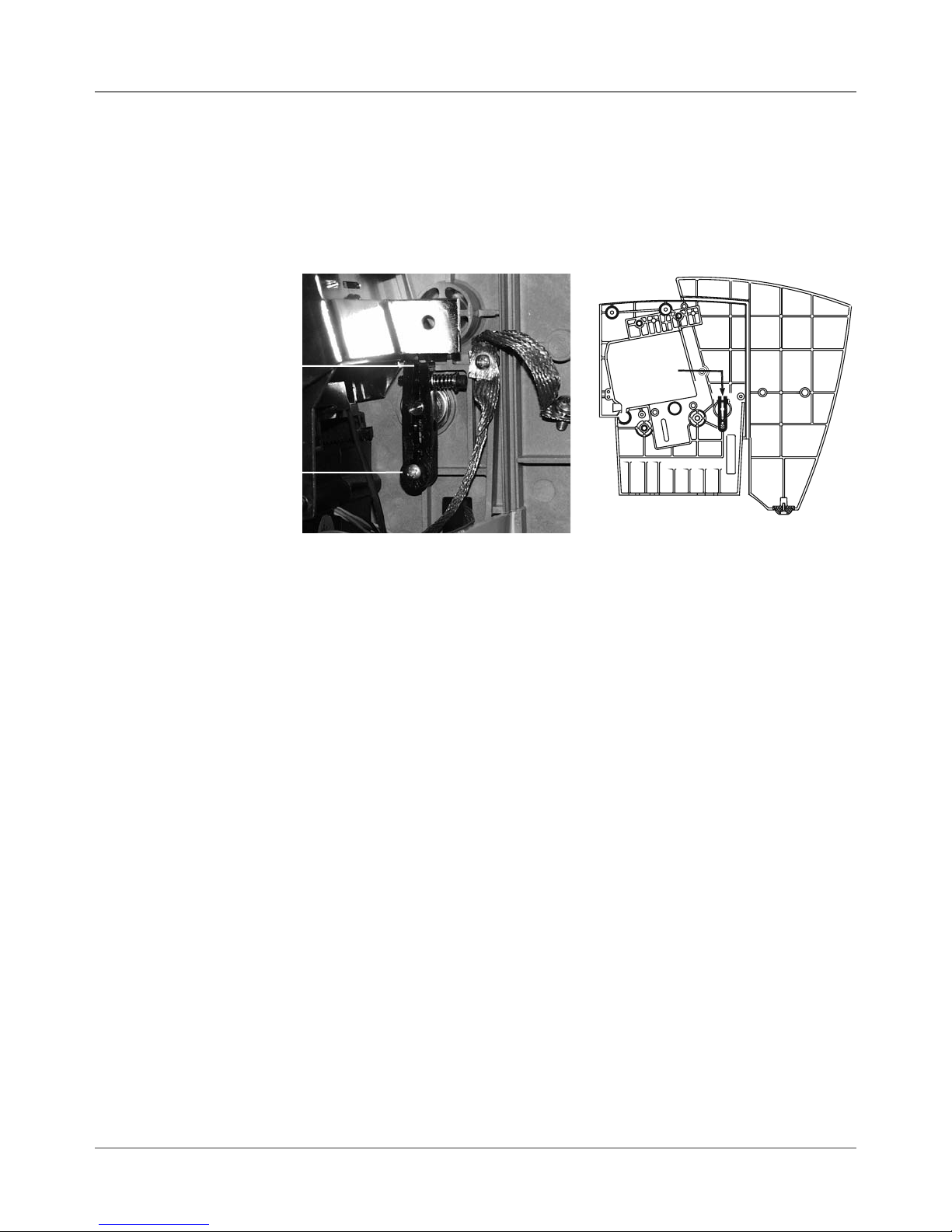
DA50S/DA55S (WS51/WS56) Adjustments
Adjustments • 6
6.4 Main Brake
Measure
here
Adjustment
Screw
Use a Phillips screwdriver and a feeler gauge to adjust the brake gap to
0.100” ± 0.020” (about 3/32”) between the two legs as shown below.
If stream feeding occurs after you set the proper gap, replace the brake assembly (see Chapter 5 for instructions).
-EASURE
HERE
2EAR3UPPORT0LATE!SSEMBLY
Figure 6-2 Brake Assembly
DA50S/DA55S/DA70S/DA75S AddressRight™ Printers Service Manual
6-3
Page 72

6 • Adjustments
DA50S/DA55S (WS51/WS56) Adjustments
6.5 Print head
Clearance
The gap between the surface of the print head and the floor of the printer is
nominally 0.040” across the entire length of print head travel with the media
thickness lever all the way down. Once set, it should not be necessary to readjust. Follow the procedure below:
1. Open the top cover.
2. Move the print head to its extreme left position—close to the media thickness lever—as seen from the output end of the machine.
3. Push the media thickness lever all the way down.
4. Insert a 0.040” feeler gage between the bottom of the print head and the
floor of the printer. CAUTION: Use care when using the gage. You can
easily damage the print head.
5. Check for proper clearance. The tolerance is 0.010”. A 0.035” gage
should fit between the print head and the floor; a 0.045” gage should not.
6. To adjust:
A. Loosen the set screw on the media thickness lever’s collar. See Fig-
ure 6-3.
B. Check for the proper clearance as described above.
C. Once the clearance is established, hold the upper rail firmly in posi-
tion
D. Tighten the setscrew loosened in step a.
7. Check the adjustment at several points along the print head’s travel. Test
the printer for proper operation.
Collar
Media
Thickness
Lever
6-4 SV61831 Rev. A DA50S/DA55S/DA70S/DA75S AddressRight™ Printers Service Manual
Figure 6-3 DA50S/DA55S Shuttle Mechanism
Page 73

DA50S/DA55S (WS51/WS56) Adjustments
Adjustments • 6
6.6 Exit Roller
Idler Assembly
1. Raise the thickness adjustment lever to its highest point.
2. Check the gap between the exit roller assembly and the bottom of the
exit idler rollers. A 0.040” feeler gauge must pass freely between both
rollers. NOTE: Loosen the screws securing the adjustable roller assembly on the right to raise or lower the right side of the exit roller assembly.
3. Check that the bar is pulled all the way forward and is level. NOTE: loosen screws to adjust bar when it is angled forward or backward.
4. Check the gap with a 0.065” feeler gauge. The gauge should not slide
between the rollers.
5. Secure screws once the gap is found.
6. Also check the gap between the small diameter rollers and the floor. The
gap should be between 0.1100” and 0.180”. Replace the non-conforming
exit slide roller if the gap is not between 0.100” and 0.180” and repeat
steps 1 to 6 again.
DA50S/DA55S/DA70S/DA75S AddressRight™ Printers Service Manual
Figure 6-4 DA50S/DA55S Shuttle Mechanism
6-5
Page 74
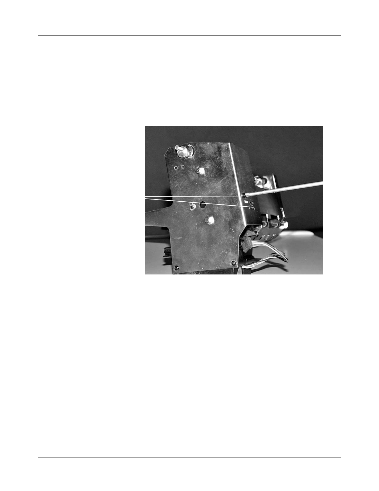
6 • Adjustments
DA50S/DA55S (WS51/WS56) Adjustments
6.7 Print Head
Drive Belt
The print head shuttle motor is mounted on an adjustable bracket as shown
at the right. To adjust belt tension:
1. Remove rear cover and shuttle driver board.
2. Move the print head holder to the park position.
3. Loosen two bracket mounting screws. See Figure 6-4.
4. Adjust the bracket until no further movement is available and then tighten.
Bracket
Mounting
Screws
Figure 6-5 DA50S/DA55S Print Head Drive Belt Adjustment
6-6 SV61831 Rev. A DA50S/DA55S/DA70S/DA75S AddressRight™ Printers Service Manual
Page 75
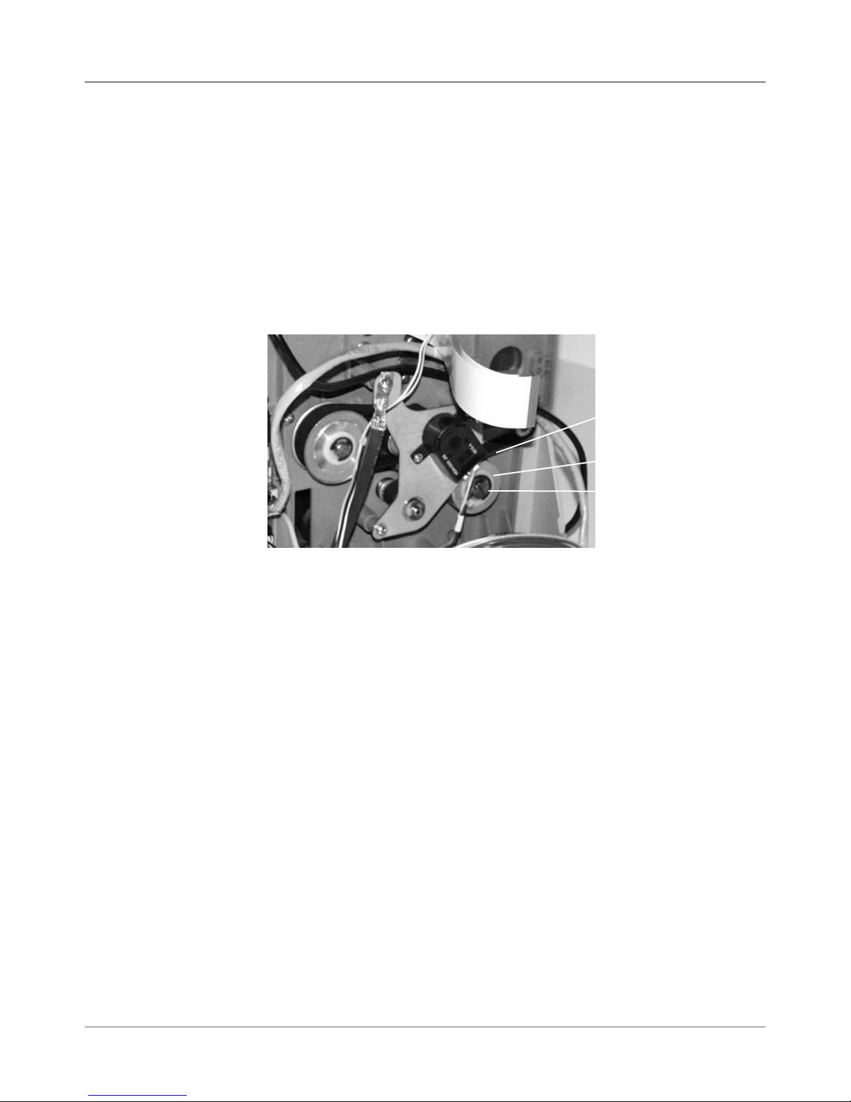
DA50S/DA55S (WS51/WS56) Adjustments
Adjustments • 6
6.8 Main Drive
Belt
Use a large flat blade screwdriver to make the following adjustment:
1. Remove operator and non-operator side covers (see section 5.1A).
2. Remove main processor board/grounding sheet assembly (see section
5.3A).
3. Loosen the shoulder screw on the pulley assembly (adjustable pulley),
see figure below. NOTE: DO NOT turn this screw all the way out.
4. The compression tensioner will set the proper tension for the belt. Tighten the slotted shaft to secure the pulley in place.
Drive Belt
Belt
Tensioner
Shoulder
Screw
Figure 6-6 DA50S/DA55S Main Drive Belt Adjustment
DA50S/DA55S/DA70S/DA75S AddressRight™ Printers Service Manual
6-7
Page 76

6 • Adjustments
DA50S/DA55S (WS51/WS56) Adjustments
6.9 Service
Station
Assembly
To determine the home position of the Print Head Holder Assembly and adjust the Service Station Assembly to seal the ink cartridge.
1. Make sure the ink cartridges are installed in the Print Head Holder Assembly, both color and black.
2. Adjust the Print Head Stop Set Screw to 0.20” and make sure the tab on
the Print Head Holder lines up perfectly with the posts on the sled.
3. Cycle the Sled Cover on the Service Station Assembly back and forth to
make sure the seals cover the ink cartridges.
4. With the rack all the way in its forward position. Raise the front and rear
of the Service Station as required to seal both heads. The gap between
the top of the Service Station Sled Cover and the bottom of the ink cartridge should be around 0.180”. Tighten both screws to secure the Service Station Assembly in place.
5. Cycle the Sled Cover again to make sure the Print Head goes to the
home position, both Ink Cartridges are sealed and the rack travels all the
way forward.
Figure 6-7 DA50S/DA55S Service Station Assembly Adjustment
6-8 SV61831 Rev. A DA50S/DA55S/DA70S/DA75S AddressRight™ Printers Service Manual
Page 77

DA50S/DA55S (WS51/WS56) Adjustments
6.9 Service
Station
Assembly
(continued)
Post
Sled
Adjustments • 6
Figure 6-8 DA50S/DA55S Service Station Assembly Adjustment
DA50S/DA55S/DA70S/DA75S AddressRight™ Printers Service Manual
6-9
Page 78

6 • Adjustments
DA70S/DA75S (WS71/WS76) Adjustments
6.10 Main
Brake
Use a 7/64” Allen wrench and a feeler gauge to reduce the gap to .020” between the two legs of the main brake.
If stream feeding occurs after you set the proper gap, replace the brake assembly (see Chapter 6 for instructions).
Measure Gap Here
Screws for
Tensioner
Brake
Assembly
Figure 6-9 DA70S/DA75S Brake Adjustment
6.11 Print Head
Drive Belt
The Print Head Drive Belt tension is set with the adjustable pulley assembly.
Use a Force Dial Gauge with an “L” shaped hook when resetting the tension.
1. Move the print head holder to the park position.
2. Loosen the adjustable pulley assembly. DO NOT FULLY UNDO.
3. With the Force Dial Gauge, pull on middle of the rear of the Print Head
Drive Belt to 8.0 ounces of force (± 2 oz), (just as the rear touches the
front of the belt).
4. Tighten the adjustable pulley.
Drive Belt
Shoulder
Screw
Figure 6-10 DA70S/DA75S Print head Drive Belt
6-10 SV61831 Rev. A DA50S/DA55S/DA70S/DA75S AddressRight™ Printers Service Manual
Page 79

DA70S/DA75S (WS71/WS76) Adjustments
Adjustments • 6
6.12 Timing
Belt
6.13 Drive Belt
The Timing Belt for the feed roller and pulley assemblies is firmly set utilizing the adjustable Idler Pulley Assembly. Use a Force Dial Gauge with a “L”
shaped hook when resetting the tension.
1. Loosen the two screws to the Idler Pulley with a screwdriver.
2. Pull on the belt at the midpoint of the longest span between two pulleys.
With the Force Dial Gauge, obtain a 2 pound force (± 4 oz) (when the
belt is deflected a distance of 1/4”).
3. Secure the Idler Pulley in place.
Adjustable
Idler Pulley
Assembly
Screws
Figure 6-11 DA70S/DA75S Timing Belt
The Drive Belt for the feed roller and pulley assemblies are firmly set utilizing
the adjustable pulley assembly. The tension is automatically set by the
springs pressing up on the adjustable pulley assembly.
NOTE: To check the belt tension use a Force Dial Gauge with a “L” shaped
hook. Pull on the belt at the midpoint of the longest span between two pulleys. With the Force Dial Gauge, pull until a measure of 2.75 pounds of force
(± 4 oz) is obtained (when the belt is deflected a distance of 1/4”).
Timing Belt
Timing Pulley
1. Loosen the drive belt adjustment pulley with a flat blade screwdriver. DO
NOT FULLY UNDO.
2. Pull up on the pulley and release it. This removes slack in the belt. The
spring beneath the pulley holds it in place with the proper tension.
3. Tighten the adjustable pulley.
Figure 6-12 DA70S/DA75S Drive Belt
DA50S/DA55S/DA70S/DA75S AddressRight™ Printers Service Manual
Drive Belt
Adjustable Pulley
6-11
Page 80

6 • Adjustments
DA70S/DA75S (WS71/WS76) Adjustments
6.14 Print Head
Home Position
In order for the Service Station to properly position and seal the Print Heads,
the Print Head home position and the Service Station must be in proper
alignment. The finger on the Service Station locks with the protruding tip on
the bottom of the Print Head Holder to press seal the Service Station wipers
against the Print Heads to prevent drying and clogging of the ink jets.
The alignment must be such that during movement of the Service Station
Sled, its finger does not miss, and locks with, the protruding tip on the Print
Head Holder.
Realignment will be necessary if the Service Station or the Print Head Holder
is removed, or if over a period of time the set screw becomes loose, altering
the Print Head home position.
The Print Head home position screw is located on the U-Channel’s rear
plate. (Remove the rear cover for access.)
Print Head Home
Position Set Screw
Figure 6-13 DA70S/DA75S Print Head Home Position Set Screw
6-12 SV61831 Rev. A DA50S/DA55S/DA70S/DA75S AddressRight™ Printers Service Manual
Page 81

7 • Preventive Maintenance
7.1 General
This chapter discusses preventive maintenance for the DA50S/DA55S
(WS51/WS56) and DA70S/DA75S (WS71/WS76) shuttle head printers.
WARNING: Unplug the printer before performing any or
cleaning or maintenance.
CAUTION: Clean the print head cartridge, ink surfaces and
covers with plain water. Clean all rubber rollers with isopropyl, denatured, or rubbing alcohol only. Keep petroleum
based cleaning solvents from contacting rubber or plastic
parts. The use of anything but alcohol will cause premature
breakdown of the rubber compound.
General
Follow these standard procedures when performing preventive maintenance:
1. Ask the operator to report any problems. If problems were noted, try to
determine if they were due to operator error, out-of-spec materials or a
machine fault.
2. Print several test sheets to evaluate print quality.
3. Clean the printer as explained below.
4. Retest the printer and check print quality again.
5. Tell the operator what you’ve done.
Items Needing Cleaning Periodically
• Main feed rollers
• Input stacker components
• Feed deck
• Exit rollers and idlers
• Paper Sensor
• Print head
• Print head Shaft
• Pan Assembly
DA50S/DA55S/DA70S/DA75S AddressRight™ Printers Service Manual
7-1
Page 82

7 • Preventive Maintenance
7.2 Specific Maintenance
Item What To Do How Often
Feed Rollers
Feed Deck And
Covers
Exit Idler Rollers
Maintenance
Station
Paper Sensor
Lint and paper dust tend to build up on the feed rollers over
time. Clean the rollers as needed, especially when they appear glazed or have a yellowish residue. Use a soft cotton
cloth, dampened with alcohol, to clean all rubber rollers.
If the tires on the main feed rollers have deteriorated to the
point that cleaning cannot restore them, replace them. See
Chapter 5 of this manual for instructions.
Periodically wipe the machine covers and deck assembly
with a soft, cotton cloth dampened with water only.
If the idler rollers are misaligned, it is possible for ink to transfer from the material onto the roller surface.
Use a soft cloth dampened with water to remove the ink from
the rollers.
Clean the caps and wipe with damp cloth or paper tower
With use, a dusty film builds up on the sensor. This can eventually cause misfeeds.
Monthly or
as Needed
Quarterly
Monthly or
as Needed
Monthly or
as Needed
Weekly
Print Head
Print head Shaft
Pan Assembly
Use compressed air to blow dust from the sensor. If a film
has developed over the sensor, remove the sensor and clean
it with alcohol. See Chapter 5 of this manual for removal instructions.
The print head periodically performs a self cleaning cycle. If
print quality is unacceptable, select the Purge function from
the Setup Menu.
If problems still persist perform the following:
• Wipe the print head cartridge nozzles using a soft cotton
cloth dampened with water.
• If cleaning doesn’t fix the problem, install a new ink car-
tridge.
• Check the flex circuit for crushed dimples
A dusty film can accumulate on the print head shaft and prevent the print head carriage from positioning itself accurately;
this can adversely affect print quality.
During every PM, wipe the print head rails clean with a lintfree cloth. DO NOT apply a lubricant of any type.
The pan assembly at the bottom of the printer collects paper
dust.
As Needed
Monthly or
as Needed
Annually
Remove the bottom Pan Access Cover periodically and clean
dust from the printer.
7-2 SV61831 Rev. A DA50S/DA55S/DA70S/DA75S AddressRight™ Printers Service Manual
Page 83
Appendix A • Printer Control
Panel Menus and Utilities
A.1 Control
Panel Menus
for the Printer
✍
TIP: Except for this
overview in Section
A.1, this chapter
deals only with the
LCD control panel
functions. For more
information on the
control panel software, refer to its builtin help.
This chapter discusses the configuration of the printer using the control panel
menus/utilities provided on the printer LCD display. However, you have the
option of installing and using the Control Panel Software on a host PC communicating to the printer via an established USB or network communications
link. The two control panel versions are contrasted in the table below, while
an overview of the Control Panel Software is provided on the next page.
Comparison of the Control Panel Menus (LCD and Software)
Item LCD Control Panel Software on Host PC
Menu Access From buttons on the control
panel
Levels of Access Determined by which
control panel buttons are
pushed in what order
Menus/Functions Main Menu
Setup Menu
Service Menu
Setting Factory Defaults
Updating Firmware
Notes More features over previ-
ous menu versions
From a shortcut launched from
the customer’s PC communicating with the printer
Determined by logon password:
Standard (no password)
Supervisor (55555 password)
Service (32322 password)
Status tab
Job Control tab
Alignment tab
Configuration tab
Test & Adjust tab
Preference/Info tab
Service tab
• Easier to navigate than two-line
LCD control panel.
DA50S/DA55S/DA70S/DA75S AddressRight™ Printers Service Manual
• Some functions are enhanced
when accessed from the software, such as setting and
monitoring ink levels, displaying
printer status, setting communications protocol, demo address
customization, and viewing log
files.
• Includes robust help system to
help you use the features.
A-1
Page 84
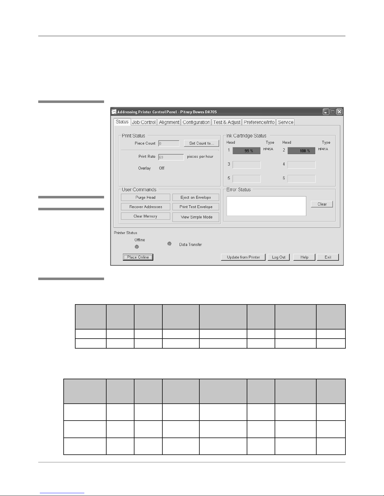
Appendix A • Printer Control Panel Menus and Utilities
A.1 Control
Panel Menus
for the Printer
✍
TIP: For most customer applications,
you will use the software control panel
application (on the
host PC) to configure
the printer. For more
information on this application, see its builtin help.
✍
TIP: Certain options of
control panel software
are only available if
the printer is OFFLINE
and if you log on with
the appropriate level of
password.
Control Panel Software Option on Host PC
The control panel software option, when loaded on a host PC communicating
with the printer (via USB or network connection), allows you to access to all the
menu and setup functions you would find on the printer’s LCD panel, as well as
run other programs unique to the control panel software (see figure below).
Main Screen of Control Panel Software Option on Host PC
Feature/Tab Access on Control Panel Software by Online/Offline State of Printer
State Status
Tab
OFF Line Yes Yes Yes Yes Yes Yes Yes
ON Line Limited No No No No No No
*Assuming you have logged on with the appropriate password
Job
Control
Tab
Alignment
Tab
Configuration
Tab
Test &
Adjust
Tab*
Preference/
Info Tab
Service
Tab*
Feature/Tab Access on Control Panel Software by Logon Password (in Off line State)
Logon Status
Tab
Standard (No
password)
Supervisor
(55555)
Service
(32322)
A-2 SV61831 Rev. A DA50S/DA55S/DA70S/DA75S AddressRight™ Printers Service Manual
Yes Yes Yes Limited No Yes No
Yes Yes Yes Yes Yes Yes No
Yes Yes Yes Yes Yes Yes Yes
Job
Control
Tab
Alignment
Tab
Configuration
Tab
Test &
Adjust
Tab
Preference/
Info Tab
Service
Tab
Page 85
Printer Control Panel Menus and Utilities • Appendix A
A.2 LCD
Control Panel
Menu
✍
TIP: LCD printer
control panel menus
can only be accessed
when the printer is in
the “offline” mode.
✍
TIP: Virtually all of
the settings in the
printer control main
menu and setup
menu are overruled
by the Windows application sending the
print job to the printer.
Features of LCD Control Panel Menus on the Printer
From the LCD control panel, you can access three main menus as well as
several other utilities.
Item Function Access Page
Main Menu Configures the appearance of the media User A-4
Setup Menu Configures the communication method used
between the printer and the host computer
Service Menu Assists in troubleshooting printer problems or
to perform corrective alignment for printing barcodes and addresses
Setting Factory
Defaults
Updating
Bootloader/
Firmware
Resets all menu settings to factory default values
Allows you to correct or update the firmware or
bootloader running the printer
User A-9
Service
Only
Service
Only
Service
Only
A-19
A-24
A-26
Accessing the LCD Menus
Press On Line. The LCD displays “OFF LINE” and the green light goes out.
• For Main Menu, press Menu.
• For Setup Menu, press and hold Menu for four seconds.
• For Service Menu, press Eject - first, then while holding it down, press
Menu together for two seconds.
Navigating Within the Menus/Changing Settings
• Press Eject - or Cartridge + to scroll through the menu options.
• Press Enter to select the desired menu option or a submenu option.
• Press Eject - or Cartridge + to scroll through the submenus within a
menu option or the settings within a menu/submenu option. An asterisk
(*) before the setting indicates that setting is currently selected.
• Press Enter to define a new setting and an asterisk will appear before
the setting indicating you have selected it.
• Press Menu to move up a level (for example, to move from a setting to a
menu option or from a menu option to “OFF LINE”).
Exiting the LCD Menus
• Press Menu until the printer LCD displays “OFF LINE”.
• Press On Line to enable the printer.
DA50S/DA55S/DA70S/DA75S AddressRight™ Printers Service Manual
A-3
Page 86
Appendix A • Printer Control Panel Menus and Utilities
A.3 LCD Main
Menu
✍
TIP: Press Eject - or
Cartridge + to scroll
through the submenus
within a menu or the
settings within a menu/
submenu option.
Press Enter to select
the desired menu option or a submenu option,- or to define a new
setting.
✍
TIP: Virtually all of the
settings in the printer
control main menu
are overruled by the
Windows application
sending the print job
to the printer.
To access the Main Menu:
Press On Line. The LCD displays “OFF LINE” and the green light goes out.
Press Menu.
Main Menu
1. Address Layout
a. Distance to right
b. Distance to bottom
c. Line Spacing
d. Inverted Printing
e. Orientation
f. Orientation Control
2. Print Quality
a. Quality
b. Light Mode
3. Font
a. Name
b. Size
c. Bold
d. Italic
4. Barcode
a. Location
b. 9 Digit On/Off
c. Bar Width
5. Address Recovery
a. Get Addr (batch)
b. Get Addr (inter)
c. Clear Memory
6. Clear Counter
7. Job Settings
a. Load
b. Save
8. Image Overlay
a. Capture Overlay
b. Clear Overlay
c. Print Overlay
A-4 SV61831 Rev. A DA50S/DA55S/DA70S/DA75S AddressRight™ Printers Service Manual
Page 87

Printer Control Panel Menus and Utilities • Appendix A
A.3 LCD Main
Menu
1. Address Layout
Submenu Option Settings What It Does
A. Distance to
Right
(or “Distance to
Left” if Inverted
Printing option is
set to inverted)
B. Distance to
Bottom
(or “Distance to
Top” if Inverted
Printing option is
set to inverted)
C. Line Spacing Automatic,
D. Inverted
Printing
0 to 9.40
inches in
0.01 in increments,
(0 -324mm
in .1 mm
increments)
0 to 15.00
inches in
0.01 in increments
(0 -343mm
in .1mm
increments)
3, 4, 5, 6, 8
(lines/inch)
Normal or
Invert
Allows you to adjust the distance from the right
edge of the media to the first printable character.
NOTE: If “Distance to Left” is displayed, value
represents the distance from the left edge
of the media to the first printable character.
Allows you to adjust the distance between the
bottom edge of the media and first line of the
address. Minimum distance between the last
line of the address and the bottom edge of the
material is 5/8 inches. If less than 5/8 inches,
the lower right barcode will not print.
NOTE: If “Distance to Top” is displayed, value
represents the distance between the top
edge of the media and first line of the address.
Whenever scalable fonts are used, automatic
line spacing is recommended. Automatic line
pitch selection is based on industry-standard
definitions for line spacing for each print pitch
and style selected. The printer automatically
selects the correct setting for the font and size
of the characters being printed.
When set to Normal, the leading edge of the
material is considered to be the bottom with the
right edge running against the side of the printer.
Setting to Invert tells the printer that the top of
the material enters and exits first, and that the
material's left edge runs along the side of the
printer.
NOTE: The setting in this option changes how
the “Distance to Right” and “Distance to Bottom”
submenu options display (see above) because
of the inverted prospective.
E. Orientation Portrait or
F. Orientation
Control
DA50S/DA55S/DA70S/DA75S AddressRight™ Printers Service Manual
Landscape
Automatic
or Manual
Changes the printing orientation between portrait or landscape
Changes the orientation between automatic,
(the printer acknowledges the orientation commands sent from the computer) or manual
(printer uses the menu settings for orientation)
A-5
Page 88

Appendix A • Printer Control Panel Menus and Utilities
A.3 LCD Main
Menu
✍
TIP: Currently, the
Barcode-only fonts,
such as Code 39, are
not selectable from the
list of fonts, but are
printed (or listed in the
control panel) as available fonts. There isn’t
a good test output for
barcode fonts, as the
font output prints the
name of the font in the
characters of the font.
2. Print Quality
Submenu Option Settings What It Does
A. Quality Executive,
Letter, Draft
B. Light Mode Off, On If OFF, the vertical print density is 600 dpi.
Executive (600 DPI) - offers the darkest of
the three print qualities and prints material
at the highest resolution, slowest speed and
uses the most ink. Use when a professional
appearance is required.
Letter Quality (300 DPI) - use for envelopes
that require a finished, polished appearance.
Draft (150 DPI) - yields the lightest image of
the three, the lowest resolution and the highest print speed. Draft quality prints envelopes
faster and saves ink.
If ON, the vertical print density is 300 dpi.
3. Font
Submenu Option Settings What It Does
A. Name Arial, Comic
Sans MS,
Courier New,
Georgia,
Impact, Kino,
MSLogo,
Symbol, Tahoma, Times
New Roman,
Trebuchet
MS, Verdana,
Webdings,
and Wingding
B. Size 4 - 144 point Sets the font size from 4 to 30 point.
Allows you to choose the font for your printing.
NOTE: When “A. Name” displays and Test
Env. is pressed, all the installed fonts names
are printed using their font characters along
with their Typeface IDs using Courier.
NOTE: When the name of the font displays
(Courier, Times New Roman, etc.) and Test
Env. is pressed, all the characters used in
the currently selected symbol set are printed,
16 characters to a row from code 0x20 to
code 0xFF in 12 point font.
C. Bold Off, On Turns bold characters On or Off. Bold char-
D. Italic Off, On Turns italic characters On or Off. Italic char-
A-6 SV61831 Rev. A DA50S/DA55S/DA70S/DA75S AddressRight™ Printers Service Manual
acters have increased stroke weight (line
thickness) and therefore print darkest. Use
bold to emphasize text in an address.
acters have decreased stroke weight, print
at an oblique angle and print lightest. Italic
characters mimic script (handwriting) and are
used to emphasize text in an address that
requires a finished, polished appearance.
Page 89

Printer Control Panel Menus and Utilities • Appendix A
A.3 LCD Main
Menu
✍
TIP: Address recovery
is used when a number
of pieces have been
jammed or are unusable for some reason
(e.g., low ink), but the
majority of the run is
either completed or
still to be processed. In
this situation, you can
use address recovery
to print the ‘damaged’
pieces from the printer
memory and then continue the job normally.
✍
TIP: Clear Memory
clears the stored address recovery ‘file’
before starting a new
job. This ensures that
pieces for a previous
job are not left over and
recovered as part of the
current job.
4. Barcode
Submenu Option Settings What It Does
A. Location Lower Right
Corner, Above
Address, Below Address,
Off
B. 9-Digit On/Off Off, On The printer automatically prints a delivery
C. Bar Width Narrower,
Narrow,
Normal, Wide,
Wider
Allows you to select where to print the U.S.
Postal Service POSTNET™ Barcode.
point barcode whenever an 11-digit ZIP
Code is present, or if delivery point barcode
information is supplied
The printer will apply this option’s settings to
the POSTNET, PLANET Code, and 4-State
barcodes.
5. Address Recovery
Submenu Option Settings What It Does
A. Get Addr (batch) Scrolling of
addresses to
select from
B. Get Addr (inter) Scrolling of
addresses to
select from
C. Clear Memory Yes, No Allows you to clear the address recovery
Allows you to retrieve any address in the
data buffer. The first 16 character of the
selected address are shown. The characters
will be ‘cryptic’ in a Windows (non-DOS) application. (There is a special PCL command
that is sent at the beginning of the print job
called the Character Mangling command
that is used by this option so ‘cryptic’ characters are NOT displayed.) When you have
reached the end of the addresses in the
recovery buffer, “None to Recover” displays.
When the printer goes back on-line, printing
resumes at the recovered page.
Allows you to retrieve any address in the
data buffer using an alternate method. The
last address printed (N) is reprinted when the
‘+’ key is pressed. If the ‘+’ key is pressed
again, the N-1 address is reprinted, and so
on until the recovery buffer is exhausted.
When the printer goes back on-line, printing
resumes with the first ‘non’ recovered page.
memory when you press the + (Plus) button
while Clear Memory is displayed. A confirmation screen is displayed if YES is selected. If
you do not wish to clear memory, press the
– (Minus) button to exit the Clear Memory
option. You would use this once a job is in
the printer (not in the PC print queue) and
you want to clear the internal buffer if you
want to start over with a known printer state.
DA50S/DA55S/DA70S/DA75S AddressRight™ Printers Service Manual
A-7
Page 90

Appendix A • Printer Control Panel Menus and Utilities
A.3 LCD Main
Menu
✍
TIP: The printers have
the ability to hold 20
job presets in memory.
This eliminates the
need for changing
printer setup when
changing print jobs.
6. Clear Counter
Submenu Option Settings What It Does
Clear address
(pcs) counter?
(yes/no)
Yes, No Allows you to clear the address piece count
accumulating in the printer’s memory.
7. Job Settings
Submenu Option Settings What It Does
A. Load Entry of job
number (from
1 - 20)
B. Save Entry of job
number (from
1 - 20)
Allows you to retrieve (by a number) a previously saved job setup.
NOTE: The first 14 characters of the job
name are displayed below the job number.
The job name is optional and is entered via
the control panel application.
Allows you to save the current setup configuration (printer settings) as a job number (1
through 20). Keep a record of these configurations and the assigned number for each
configuration.
✍
TIP: The image overlay feature allows you
to “capture” an image from another job
or print file, save it to
memory, and then print
it (“overlay”) the image
on the envelope with
your print job that may
contain, say, addresses
only. This way, you can
add (print) that image
on every envelope in
a job without having
to set up the graphic
in an envelope design
program (such as Envelope Designer Plus).
Mostly used in a nonWindows environment.
8. Image Overlay
Submenu Option Settings What It Does
A. Capture Overlay Yes, No When YES is selected, the printer is set to
use the next page received from the host
computer as an overlay. The “Next page will
be used as overlay” message is displayed for
two seconds, and you return to Image Overlay sub-menu. If NO is selected, you return
to Image Overlay sub-menu.
B. Clear Overlay Yes, No When YES is selected, the printer clears the
overlay memory buffer. The “Overlay has
been cleared.” message is displayed for two
seconds, and you return to Image Overlay
sub-menu. If NO is selected, you return to
the Image Overlay sub-menu.
C. Print Overlay Enabled,
Disabled
Allows you to turn the overlay feature ON or
OFF.
A-8 SV61831 Rev. A DA50S/DA55S/DA70S/DA75S AddressRight™ Printers Service Manual
Page 91

Printer Control Panel Menus and Utilities • Appendix A
A.4 LCD Setup
Menu
✍
TIP: Press Eject - or
Cartridge + to scroll
through the submenus
within a menu or the
settings within a menu/
submenu option.
Press Enter to select
the desired menu option or a submenu option, or to define a new
setting.
✍
TIP: Virtually all of the
settings in the printer
control setup menu
are overruled by the
Windows application
sending the print job
to the printer.
To access the Setup Menu:
Press On Line. The LCD displays “OFF LINE” and the green light goes out.
Press and hold Menu for two seconds.
Setup Menu
1. Heavy Media Mode
2. Test Print Head
3. Purge Print Head
4. Lines Per Address
5. Communications
a. TCP/IP
b. Line Termination
c. Clear Memory
6. Hex Dump Mode
7. Language
a. Symbol Set
b. Inch/Millimeter
c. Menu Languages
8. Envelope Feed Delay
9. Envelope Auto Eject
a. Auto Eject Mode
b. Mode
13. Tray Break*
a. Enable/Disable
b. Break Character
c. Break Character Count
d. Character Orientation
e. Break Location
f. Print Break Characters
g. Break Pause Time
14. Low Ink Warning
a. Display Warning
b. Warning Threshold
c. Stop When Empty
15. Logging Settings
a. Enable Logging
b. Logging Level
10. ROM Revision #
11. Print Head Maintenance
a. Head Maintenance
b. Maintenance Cycle Time
12. Bundle Break*
a. Enable/Disable
b. Break Character
c. Break Character Count
d. Character Orientation
e. Break Location
f. Print Break Characters
g. Break Pause Time
*The Bundle Break and Tray Break features are not functional
at the time of this writing but are planned for a future release.
DA50S/DA55S/DA70S/DA75S AddressRight™ Printers Service Manual
A-9
Page 92

Appendix A • Printer Control Panel Menus and Utilities
A.4 LCD Setup
Menu
✍
TIP: See Chapter 4,
Diagnostics/Troubleshooting for samples
of good and poor test
prints and for troubleshooting printing
problems.
✍
TIP: One characteristic of ink jet systems
is that when a jet is
not used regularly, it
tends to clog up with
dried ink. This leaves
lines across the print,
especially in graphics. To avoid this, the
system must periodically fire and clean all
of the nozzles on the
print head. This activity is called purging.
These printers are
designed to purge
the head at specific
intervals depending
on the print density.
Any time that the print
quality appears to be
deteriorating and the
cartridge is not low on
ink, a purge is a good
way to restore print
quality.
1. Heavy Media Mode
Menu Option Settings What It Does
Heavy Media
Mode
Off, On Allows you to increase the transport motor
torque for a media stack that is exceeds 10
pounds. NOTE: Throughput is decreased by
approximately 10% when this feature is on.
2. Test Print Head
Menu Option Settings What It Does
Test Print Head Yes, No Allows you to print a test pattern to deter-
mine if the print heads are functioning properly. For this option, material must be loaded
in the printer input bin. When prompted to
run, press Enter and the printer displays
“Please wait... Test pattern is printing.” The
ink jet cartridge prints a table of rows and
columns across the material. If a gap is present in any of the rows, one or more nozzles
may be blocked and need cleaning. A wavy
line indicates a partial blocked nozzle. You
can purge the nozzles (see next menu item
below) or use a soft cotton cloth with or without water to clean the printhead. If purging or
cleaning the printhead doesn’t work, then try
a new ink cartridge.
3. Purge Print Head
Menu Option Settings What It Does
Purge Print Head Yes, No Allows you to purge the print head which
may clear clogged ink from the print nozzles.
Often this returns print quality to a satisfactory level. When prompted to run, press
Enter and the printer displays “Please wait...
Ink jets being purged.”
4. Lines per Address
Menu Option Settings What It Does
Lines per Address Entry of 1 - 66
lines per address
Allows you to specify the number of lines in
the printed address. The printer can print an
address which is typically between 3 to 8
lines.
A-10 SV61831 Rev. A DA50S/DA55S/DA70S/DA75S AddressRight™ Printers Service Manual
Page 93
Printer Control Panel Menus and Utilities • Appendix A
A.4 LCD Setup
5. Communications
Menu
Submenu
Option
A. TCP/IP A. DHCP Enabled,
B. Line
Termination
C. Clear
Memory
(for deleting a print
job)
Additional Options Settings What It Does
Disabled
B. IP Address 000.000.000.00
(000 to 255 for each address
segment)
C. Subnet Mask 000.000.000.000
(000 to 255 for each address
segment)
D. Gateway Address 000.000.000.000
(000 to 255 for each address
segment)
E. Port Number 5100 (default) Allows you to select a communica-
(CR = CR; LF = LF),
(CR = CR + LF; LF = LF),
(CR = CR; LF = CR + LF),
(CR = CR + LF; LF = CR + LF)
Yes, No Allows you to clear the data commu-
Allows you to enter printer communication settings for networking.
If DHCP is enabled and you press
Enter, the system displays “Device =
xxxxxxx” (the device name, such as
ARPTR1B2C). The system also dis-
plays the assigned IP address, Sub-
net Mask, and Gateway address in
the corresponding menu items (items
B, C, and D) as read-only; you can
not change them.
If DHCP is disabled, pressing Enter
saves the current address element
and moves to the next address elements. The system blinks the segment that is currently selected. When
the + or - keys are pressed (and held
for less than two seconds), the printer
increments or decrements the values
of the selected segment by 1. When
the + or - keys are pressed and held
for at least two seconds, the printer
increments or decrements the value
by 10. Pressing Menu saves/sets the
entire address and exits the TCP/IP
submenu.
tions port from your PC to the printer
Allows you to specify how the printer
ends a line. Typical software line termination is CR = CR; LF = LF. If your
software does not use this, then you
can modify the line termination.
nications of a print job (this is not the
same as clearing the address recovery memory in the Main Menu).When
clearing a print job, you should also:
DA50S/DA55S/DA70S/DA75S AddressRight™ Printers Service Manual
1. Take printer off line.
2. On host PC, go to Settings>
Control Panel>Printer. Right click on
desired printer.
3.Locate print job to cancel. Right
click on it; go to Document>Cancel.
A-11
Page 94
Appendix A • Printer Control Panel Menus and Utilities
A.4 LCD Setup
Menu
6. Hex Dump Mode
Menu Option Settings What It Does
Hex Dump Mode Off, On Allows you to print raw ASCII data. This is
very useful when troubleshooting computer
(software) installation problems. See the
HEX—Decimal Conversion Chart on the next
page.
When HEX Mode is disabled, a standard address prints on a single envelope. With Hex
Mode enabled, the same address prints on
several envelopes (3 to 5). This happens because in HEX mode there are four elements
printed for each character in the address.
Each HEX code is two digits long separated
by brackets. A capital letter A is a Hex [41].
When reviewing addresses printed in HEX
mode, start from the end of the address
at the ZIP Code (remember 30’s are the
numbers) and count backwards toward the
beginning of the address. Count the number
of carriage returns, CR [0D], and line feeds,
LF [0A]. Check that the printer’s address
setup has the same number of CRs and LFs
as the address printed. If a variation exists in
the number of CRs or LFs between addresses, you MUST terminate the address with a
(form feed) FF [0C].
To print a hex dump once you’ve enabled the
mode, press the Menu button to back out of
the menu until the printer displays Off Line.
Then press On Line and send addresses to
the printer.
A-12 SV61831 Rev. A DA50S/DA55S/DA70S/DA75S AddressRight™ Printers Service Manual
Page 95

Printer Control Panel Menus and Utilities • Appendix A
A.4 LCD Setup
Menu
6. Hex Dump Mode (continued)
MSB
0 16 32 48 64 80 96 112
0 1 2 3 4 5 6 7
HEX
0
NUL
DLE
SP
0
1
SOH
DC1
2
STX
DC2
3
ETX
DC3
4
EOT
DC4
5
ENQ
NAK
6
ACK
SYN
7
BEL
ETB
8
BS
CAN
9
NT
EM
A
LF
SUB
B
VT
ESC
C
FF
D
CR
GS
E
SO
RS
SI
F
US
FS
!
1
"
2
#
3
$
4
%
5
&
6
′
7
(
8
)
9
*
:
+
;
,
<
–
=
•
>
/
?
LSB
DEC
0
1
2
3
4
5
6
7
8
9
10
11
12
13
14
15
@
P
`
p
A
Q
a
q
B
R
b
r
C
S
c
s
D
T
d
t
E
U
e
u
F
V
f
v
G
W
g
w
H
X
h
x
I
Y
i
y
J
Z
j
z
K
[
k
{
L
\
l
|
M
]
m
}
N
^
n
-
O
_
DEL
o
HEX to Decimal Conversion Chart
Example: The capital letter A is a HEX41. Find the letter A on the above
chart, then look toward the top of the chart (MSB) and locate the HEX num-
ber 4. Then look to the left side of the chart (LSB) and locate the HEX number 1. Therefore the HEX number is MSB 4 and LSB 1= 41.
You can understand the chart on above by noting the following HEX codes:
HEX Code Alphanumeric Equivalent
41 Capital A
0D Carriage Return
0A Line Feed
0C Form Feed
30-39 0-9 (HEX 30 = 0, HEX 31 = 1, etc.
DA50S/DA55S/DA70S/DA75S AddressRight™ Printers Service Manual
A-13
Page 96

Appendix A • Printer Control Panel Menus and Utilities
A.4 LCD Setup
Menu
7. Language
Submenu Option Settings What It Does
A. Symbol Set ISO 6 ANSI ASCII
ISO 69 FRENCH
ISO 21 GERMAN
ISO 4 UK
ISO 60 NORW/DAN
ISO 11 SWED/FIN
ISO 15 ITALIAN
ISO 17 SPANISH
ISO 61 NORW/DAN
ISO 10 SWED/FIN
ISO 16 PORTUGUESE
ISO XX POLISH
ISO 8859
ROMAN 8
WINDOWS LATIN 1
PC 8
B. Inch / Millimeter Inch
Millimeter
C. Menu Languages English
German
French
Italian
Spanish
Dutch
Polish
Japanese
Allows you to select a specific
International Standards Organization (ISO) character set
based on the needs of the print
job.
Allows you to select the printer
measurement system, either
inch or millimeter.
Allows you to translate the
information displayed on the
LCD to the language selected.
8. Envelope Feed Delay
Menu Option Settings What It Does
Envelope Feed
Delay
A-14 SV61831 Rev. A DA50S/DA55S/DA70S/DA75S AddressRight™ Printers Service Manual
0.0 to 30.0
seconds
(in 0.1 second
increments)
Allows you to set an envelope feed delay
when feeding very glossy material or when
extra drying time is needed for the ink. This
option slightly reduces the overall throughput
of the printer.
Page 97
Printer Control Panel Menus and Utilities • Appendix A
A.4 LCD Setup
Menu
9. Env Auto Eject
Submenu Option Settings What It Does
A. Auto Eject
Mode
B. Mode 0.0 to 30.0
Off, On Allows you to set the printer to automatically
eject the last envelope of the job. When this
option is On, the printer ejects a blank envelope between batch jobs.
Allows you to set the amount of delay beseconds
(in 0.1 second
increments)
tween the ejection of the blank envelope (if
Auto Eject mode is On) and the start of next
batch job.
10. ROM Revision Number
Menu Option Settings What It Does
ROM Revision # ROM REV. =
xx.xx.xx
MAIN COUNT
= xxxxxx
Allows you to verify the firmware revision
installed in the printer (e.g., for CASS certi-
fication). It is also useful to determine if the
printer requires an upgrade.
The maintenance count, which is the total
number of print cycles accumulated, also
displays. This count is helpful in determining
solutions to printer problems.
NOTE: If the TEST button is pressed, all the
menu settings are printed on as many #10
envelopes as required, using 12 point Cou-
rier and in the current language.
DA50S/DA55S/DA70S/DA75S AddressRight™ Printers Service Manual
A-15
Page 98

Appendix A • Printer Control Panel Menus and Utilities
A.4 LCD Setup
Menu
✍
TIP: We suggest you
always enable the
Head Maintenance option to ensure the inkjet
nozzles do not get
clogged and you maintain good print quality.
Also, the higher the
print quality selected,
the more print head
maintenance needs to
be done because of
the increased use of
the ink jets.
11. Print Head Maintenance
Submenu Option Settings What It Does
A. Head Maintenance
B. Maint. Cycle
Time
Enabled,
Disabled
1 to 5 minutes,
(in 1 minute
increments)
Allows you to enable and disable the performance of print head maintenance cycles
during print jobs. The maintenance cycle
consists of moving the print heads to the
maintenance station, firing all the nozzles on
the ink cartridges into an ink reservoir, and
then wiping the heads.
When initially viewed, this displays the default time period (in minutes) between head
maintenance cycles when running a job, if
“Head Maintenance” is enabled. The default
settings are based on the print quality selected for your job: Executive quality is set for 2
minutes between cycles, Letter is set for 3
minutes, and Draft quality is 4 minutes. You
may override the default and lengthen the
time between cycles in an effort to increase
throughput or save some ink (both minimally).
12. Bundle Break*
*The Bundle Break
and Tray Break
features are not
functional at the time
of this writing but are
planned for a future
release.
Submenu Option Settings What It Does
A. Enable/Disable Enabled,
Disabled
B. Break Character
C. Break Character Count
D. Character Orientation
E. Break Location Before Ad-
F. Print Break
Characters
G. Break Pause
Time
! “ # $ % &
‘ ( ) * + , -
. / 0 through
9 : ; <
= > ? @ A
through Z
1 to 12 Allows you to specify the number of break
Vertical or
Horizontal
dress, After
Address
Enabled,
Disabled
0 to 30.00
seconds ( in
0.25 second
increments)
Allows you to enable or disable the detection of printer bundle breaks. The system
will detect these breaks based on strings of
characters found in the data stream.
Allows you to specify the break characters
used to identify the bundle break.
characters in the bundle break.
Allows you to specify the alignment of the
break characters as either vertical or horizontal.
Allows you to specify whether to print the
break characters before or after the address.
Allows you to specify whether to print or not
print the break characters.
Allows you to specify the length of time the
printer will pause printing when a bundle
break is detected.
A-16 SV61831 Rev. A DA50S/DA55S/DA70S/DA75S AddressRight™ Printers Service Manual
Page 99

Printer Control Panel Menus and Utilities • Appendix A
A.4 LCD Setup
Menu
*The Bundle Break
and Tray Break
features are not
functional at the time
of this writing but are
planned for a future
release.
13. Tray Break*
Submenu Option Settings What It Does
A. Enable/Disable Enabled,
Disabled
B. Break Character
C. Break Character Count
D. Character Orientation
E. Break Location Before Ad-
F. Print Break
Characters
! “ # $ % &
‘ ( ) * + , -
. / 0 through
9 : ; <
= > ? @ A
through Z
1 to 12 Allows you to specify the number of break
Vertical or
Horizontal
dress, After
Address
Enabled,
Disabled
Allows you to enable or disable the detection
of printer tray breaks. The system will detect
these breaks based on strings of characters
found in the data stream.
Allows you to specify the break characters
used to identify the tray break.
characters in the tray break.
Allows you to specify the alignment of the
break characters as either vertical or hori-
zontal.
Allows you to specify whether to print the
break characters before or after the address.
Allows you to specify whether to print or not
print the break characters.
G. Break Pause
Time
0 to 30.00
seconds ( in
0.25 second
increments)
Allows you to specify the length of time the
printer will pause printing when a tray break
is detected.
14. Low Ink Warning
Submenu Option Settings What It Does
A. Display Warning
B. Warning
Threshold
C. Stop When
Empty
Enabled,
Disabled
2 to 7 percent
(in 1 percent
increments)
Enabled,
Disabled
Allows you to set whether the printer provides a low ink warning when the ink threshold is reached.
Allows you to set the ink threshold (in
percentage of ink remaining) for the low ink
warning to display.
Allows the printer to stop when the ink has
been depleted (0 percent remaining).
DA50S/DA55S/DA70S/DA75S AddressRight™ Printers Service Manual
A-17
Page 100

Appendix A • Printer Control Panel Menus and Utilities
A.4 LCD Setup
Menu
15. Logging Settings
Submenu Option Settings What It Does
A. Enable Logging Off, On Allows the printer to record or log all events
that occur in the printer. The system catego-
rizes events into three types: user events,
machine events, and errors. User events are
actions initiated by the user. Machine events
are actions initiated by the machine hard-
ware or software or actions by the machine
that are responses to user actions. Errors
are events that are caused by exceptions
or conditions that cause the printer to stop
prematurely or unexpectedly.
B. Logging Level Standard,
Verbose
When the logging option is set to ‘Standard’,
the system will log user and error events,
where the record in the log includes the
event or error ID, the clock tick count, and
the brief description.
When the logging option is set to ‘Verbose’,
the system will log user, machine, and error
events, where record in the log includes the
event or error ID, the clock tick count, the
brief description and the detailed description.
A-18 SV61831 Rev. A DA50S/DA55S/DA70S/DA75S AddressRight™ Printers Service Manual
 Loading...