

Page 1
SERVICE SECTION
L20-055 R12 (06/11)
There's Always Something Cooking!
Service, Parts, and Schematics
For Electric Fryers With Options
Including Options, Built-In and UFM (Spacefighter)
Filter Systems
Covering Models
E7, E7B, E12, E14, E14B, E14X, E18, & E18B
Pitco Frialator, Inc., P.O. Box 501, Concord, NH 03302-0501 • 509 Route 3A, Bow, NH 03304
A BLODGETT Company
(800) 258-3708 • (603) 225-6684 • FAX (603) 225-8497
Page 2

MTS # PF05-01 Pitco Frialator #L20-055 Revision 11 Rev. Date 07/18/94
L20-055 R12 (06/11)
Page 3

TO THE PURCHASER, OWNER AND STORE MANAGER
Please review these warnings prior to posting them in a prominent location for reference.
WARNING
DO NOT store or use gasoline or other flammable
vapors and liquids in the vicinity of this or any other
appliance.
WARNING
Improper installation, alteration, service or
maintenance can cause property damage, injury or
death. Read the installation, operating and
maintenance instructions thoroughly before installing
or servicing this appliance.
WARNING
Installation, maintenance and repairs should be
performed by a Pitco Authorized Service and Parts
(ASAP) company technician or other qualified
personnel. Installation, maintenance or repairs by
unauthorized and unqualified personnel will void the
warranty.
WARNING
Installation and all connections must be made
according to national and local regulations and codes
in force.
WARNING
A country approved all pole circuit breaker with a
minimum open contact gap of 3mm must be used for
proper installation. (CE countries)
WARNING
During the warranty period if a customer elects to use a
non-original part or modifies an original part purchased
from Pitco and/or its Authorized Service and Parts
(ASAP) companies, this warranty will be void. In
addition, Pitco and its affiliates will not be liable for any
claims, damages or expenses incurred by the customer
which arises directly or indirectly, in whole or in part,
due to the installation of any modified part and/or
received from an unauthorized service center.
WARNING
This appliance, when installed, must be electrically
grounded in accordance with local codes, or in the
absence of local codes, with the National Electrical
Code, ANSI/NFPA 70, or the Canadian Electrical Code,
CSA C22.2, as applicable.
WARNING
DO NOT alter or remove structural material on the
appliance to facilitate storage or for any other reason.
WARNING
This appliance is intended for professional use only
and should be operated by fully trained and qualified
personnel.
WARNING
DO NOT use the electrical cord as a leash to move the
appliance. Series injury and appliance damage can
occur.
WARNING
If the supplied power cord or receptacle is damaged, it
must be replaced by a Pitco Authorized Service and
Parts (ASAP) company technician, or a similarly
qualified person in order to avoid a hazard.
WARNING
The power supply must be disconnected before
servicing, maintaining or cleaning this appliance.
The appliance is NOT jet stream approved. DO NOT
clean the appliance with a water jet.
DO NOT attempt to move this appliance or transfer hot
liquids from one container to another when the unit is
at operating temperature or filled with hot liquids.
Serious personal injury could result if skin comes in
contact with the hot surfaces or liquids.
DO NOT sit or stand on this appliance. The appliance’s
top panel, filter pan, filter carriage, pan cover is not a
step. Serious injury could result from slipping, falling
or contact with hot liquids.
NEVER use the appliance as a step for cleaning or
accessing the ventilation hood. Serious injury could
result from slips, trips or from contacting hot liquids.
The filter pan should be dry and free of water droplets
prior to use. Serious injury could result from hot steam
vapors when hot oil/shortening mixes with water.
DO NOT overfill filter pan with hot oil/shortening. Do
not leave appliance unattended while draining or
refilling with oil/shortening. Over filling the appliance
can cause serious injuries and damage the appliance.
The contents of the crumb catch and/or filter pan of
any filter system must be emptied into a fireproof
container at the end of each day. Some food particles
can spontaneously combust if left soaking in certain
types of oil or shortening.
Completely shut the appliance down when the
oil/shortening is being drained from the appliance. This
will prevent the appliance from heating up during the
draining and filling process. Serious injury and
appliance damage can occur.
This appliance is intended for indoor use only.
DO NOT operate appliance unless all panels and
access covers are attached correctly.
It is recommended that this appliance be inspected by
a qualified service technician for proper performance
and operation on a yearly basis
This appliance is designed to operate on a specific
voltage. This information can be found on the data
plate located on the rear of the appliance
.
WARNING
WARNING
WARNING
WARNING
WARNING
WARNING
WARNING
WARNING
WARNING
WARNING
WARNING
WARNING
2
L20-303 Rev 1. (05/11)
Page 4

Table of Contents (Service)
Section Title Page
Table of Contents (Service)..........................................................................................................i-ii
List of Figures .......................................................................................................................... ii
Chapter 4: Service .....................................................................................................................4-1
4.1 REPLACEMENT PROCEDURES ........................................................................... 4-1
4.1.1 Heating Element Removal and Replacement ...................................................... 4-1
4.1.2 Backup Thermostat Replacement - Computer Models Only............................... 4-2
4.1.3 Calibrating the Thermostat - Computer Models Only.........................................4-3
4.2 TESTING CONTACTORS (RELAYS)....................................................................4-3
4.3 TESTING HEATING ELEMENTS ..........................................................................4-4
4.4 TESTING THE TEMPERATURE SETTING POTENTIOMETERS...................... 4-4
4.5 TESTING THE TEMPERATURE CONTROL MODULES ...................................4-4
4.6 TESTING THE TEMPERATURE PROBE.............................................................. 4-5
4.7 TESTING THE HEATING ELEMENT INTERLOCK............................................ 4-5
4.8 TROUBLESHOOTING FRYERS WITHOUT COMPUTERS................................ 4-7
4.9 TROUBLESHOOTING FRYERS WITH COMPUTERS...................................... 4-14
4.10 TROUBLESHOOTING BASKET LIFT PROBLEMS ..........................................4-16
4.11 TROUBLESHOOTING BUILT-IN FILTER UNITS............................................. 4-18
4.12 TROUBLESHOOTING UFM FILTER UNITS ..................................................... 4-21
Chapter 5: Parts .......................................................................................................................5-1
Fig. No.
5-1 Outside View ............................................................................................................. 5-2
5-2 Entrance Box ............................................................................................................. 5-3
5-3 Inside Fryer Tank Components ................................................................................. 5-4
5-4 Frame-Cabinet / Electrical Assemblies With Components ....................................... 5-7
5-5 UFM Filter, Frame/Electrical Assembly ...................................................................5-9
5-6 UFM Pilter, Pick-Up/Pan Assembly ....................................................................... 5-11
5-7 UFM Filter, Motor / Return Assembly.................................................................... 5-13
5-8 Built-In Filter Pan With Components...................................................................... 5-15
5-9 Filter Piping With Components............................................................................... 5-17
5-10 Built-In Filter With Accessories.............................................................................. 5-19
ALPHABETICAL PART LIST .............................................................................. 5-20
NUMERICAL PART LIST..................................................................................... 5-24
i
Page 5

Table of Contents (Service) Cont.
Section Title Page
Chapter 6: Schematics.............................................................................................................. 6-1
List of Tables and Figures
Table No. Title Page
5-1 Frame-Cabinet / Electrical Assemblies With Components ....................................... 5-6
5-2 UFM Filter, Frame/Electrical Assembly ...................................................................5-8
5-3 UFM Pilter, Pick-Up/Pan Assembly ....................................................................... 5-10
5-4 UFM Filter, Motor / Return Assembly.................................................................... 5-12
5-5 Built-In Filter Pan With Components...................................................................... 5-14
5-6 Built-In Filter Piping With Components ................................................................. 5-16
5-7 Built-In Filter With Accessories.............................................................................. 5-18
Figure No. Title Page
5-1 Outside View ............................................................................................................. 5-2
5-2 Entrance Box ............................................................................................................. 5-3
5-3 Inside Fryer Tank Components ................................................................................. 5-4
5-4 Frame-Cabinet / Electrical Assemblies With Components ....................................... 5-7
5-5 UFM Filter, Frame/Electrical Assembly ...................................................................5-9
5-6 UFM Pilter, Pick-Up/Pan Assembly ....................................................................... 5-11
5-7 UFM Filter, Motor / Return Assembly.................................................................... 5-13
5-8 Built-In Filter Pan With Components...................................................................... 5-15
5-9 Filter Piping With Components............................................................................... 5-17
5-10 Built-In Filter With Accessories.............................................................................. 5-19
ii
Page 6

Chapter 4: Service
This chapter provides the qualified technician with the replacement and troubleshooting procedures
necessary to service the Pitco fryer.
4.1 REPLACEMENT PROCEDURES
These procedures are provided to the qualified technician as a guide to removal and replacement of
various fryer components. If a test is required to verify component operation after installation, it will
be referenced.
WARNING
To prevent burns, always ensure the fryer is completely SHUT DOWN and
COOLED down before working on the fryer. Do not break any fryer gas
connections while the unit is connected to a gas supply line.
WARNING
The power supply must be disconnected before servicing or cleaning the
appliance.
4.1.1 Heating Element Removal and Replacement
Replacing a heating element is a complex and time consuming procedure. Ensure that you have
tested the heating elements to determine that the element is bad and not something else.
a. Move the fryer out to gain access to the rear panels. Remove the upper small access cover
and the large lower access cover.
b. The terminal block for the heating elements is located behind the lower access plate. Tag
the connections with wire markers for easy reinstallation, and remove the wires. The
temperature probe wires are not connected through the terminal board. To disconnect the
temperature probe, remove the small access plate on top of the pivot box (plate opposite
High Limit switch). The connector for the probe is inside the pivot box. Disconnect the
probe at this connector and gently pull the wire out of the pivot box.
c. Disconnect the spring assembly from the pivot box by raising the elements and holding
them in place with a board across the tank. Do not use the element bracket to hold the
elements up.
d. Next remove the pivot box assembly by removing the screws that attach the pivot box
hinges to the fryer. The heating elements will need to be raised to gain access to the screw
heads. Support the heating element assembly before removing the screws. Removing
the hinge screws frees the heating element assembly from the fryer.
4-1
Page 7

e. Once free of the fryer, set the element assembly aside. Remove the access plate on the
back of the pivot box to gain access to the heating element connectors. Disconnect the
wire for the defective element.
f. Loosen the nuts that attach the heating element to the pivot box. Slide the heating element
out of the pivot box.
g. Install the new heating element by reversing this procedure.
4.1.2 Backup Thermostat Replacement - Computer Models Only
Only fryers that have computer controls have this backup thermostat. If your fryer does not have
a computer but does have a thermostat behind the door, this is a thermostat behind the door model.
That means that the knob behind the door controls the solid state temperature module behind the
fryer's control panel (front bezel). The backup thermostat includes the temperature adjustment knob,
temperature sensor inside the fryer tank, and connecting capillary tubing. The high limit controls
also has a temperature sensor in the fryer tank, so ensure you are removing the correct temperature
sensor.
CAUTION
Thermostat capillary tubing is very delicate. Be VERY CAREFUL when
working with the capillary tubing. If the tubing is kinked or broken the
thermostat is no longer usable.
a. Drain the oil from the fryer. The thermostat probe (heat sensor) is clamped to the heating
element assembly inside the tank. Unscrew and remove the two screws in the thermostat
probe clamp.
b. Remove the thermostat probe from the clamp and straighten the capillary tubing.
Unscrew the small hex nut inside the cabinet under the tank for the thermostat control.
c. Unscrew the large connector nut from the fryer tank and pull the thermostat probe and
capillary tubes through the opening.
d. Pull the knob off of the thermostat. Remove the entrance box cover to gain access to the
thermostat.
e. Mark and disconnect he wires from the thermostat terminals.
f. Remove the two screws that hold the thermostat to the inside of the entrance box. Remove
the defective thermostat control unit from the fryer.
g. Install the new thermostat in reverse order. Remember to be careful with the capillary
tubes.
4-2
Page 8

h. Use pipe joint compound on the large fitting before installing to prevent oil leakage. DO
NOT use joint compound on the small nut.
i. Perform the calibration procedures detailed in section 1.5.3.
4.1.3 Calibrating the Thermostat - Computer Models Only
To calibrate this thermostat the dial must be removed from the shaft. The adjustment for the
thermostat is inside the dial shaft.
a. To calibrate the thermostat you must first cause the computer to switch control to the
backup thermostat. To do this, remove the computer from the front panel and disconnect
the connector from the computer. The transfer relay will de-energize and temperature
control will shift to the backup thermostat.
b. Place the tip of a high accuracy thermometer in the shortening approximately 1" above
the temperature sensor.
c. Set the thermostat dial to 325°F and turn the fryer on.
d. Remove the thermostat dial by pulling the knob straight out. DO NOT rotate the dial.
e. Hold the outside of the shaft so it does not move. Use the tip of a small, flat tip screw
driver to scrape away the sealing compound from the adjustment screw. Turn the
adjustment screw clockwise to lower the temperature setting, and counterclockwise to
raise the temperature. One quarter turn will change the temperature approximately 25°F.
f. Turn the adjustment until the heating elements turn off at 325°F. Replace the knob and
allow the fryer to cycle 4 to 6 times. Check the temperature of the thermometer against
the thermostat dial, if it is greater than 5°F repeat the calibration procedure.
g. When the calibration is correct, remove the thermometer.
4.2 TESTING CONTACTORS (RELAYS)
Contactors and relays use a control voltage to energize the electro magnet and close a set of contacts.
The control voltage is applied to a solenoid-type coil. When measuring a coil's resistance, ensure that
you have disconnected it from the fryer's electrical system. This will ensure that you are measuring
the coil's resistance and not a portion of the fryer's wiring. When measured with an OHM meter these
coils should have a very low resistance, less than 100 ohms. Measure each of the contactors that are
suspect. If any relay or contactor indicates an open circuit or high amount of resistance, replace the
coil.
4-3
Page 9

4.3 TESTING HEATING ELEMENTS
To check a heating element first place the OFF-ON-START switch in OFF. Check the elements by
performing the following:
a. The terminal block that connects the heating elements to the fryer is located behind the
large rear access panel. Move the fryer out and remove the access panel.
b. Using an OHM meter check continuity from one end of the element to the other. The
reading should be very low (a few ohms). If the element indicates an open circuit, replace
the element.
c. Next check from the hot side of the element to ground. It should be infinite, if it is not
replace the element.
4.4 TESTING THE TEMPERATURE SETTING POTENTIOMETERS
The temperature setting potentiometer is a variable resistors. To test the potentiometer ensure that
the OFF-ON-START switch is OFF and perform the following:
a. For thermostat knobs mounted on the front of the fryer, remove the front bezel to gain
access to the back of the potentiometer. If the fryer has the thermostat knob mounted
behind the door (in the entrance box), remove the entrance box cover to gain access to
the back of the potentiometer.
b. Disconnect P10 from J10.
c. Connect an ohm-meter to pin 3 (yellow wire) and pin 1 (violet wire) and rotate the
temperature control knob. The resistance should vary from 0 to 900 ohms.
b. Connect the ohm-meter between pin 3 (yellow wire) and pin 5 (orange wire) and rotate
the knob. The resistance should again vary from 0 to 900 ohms. If the resistance is not
within the ranges specified replace the temperature setting potentiometer.
4.5 TESTING THE TEMPERATURE CONTROL MODULES
The temperature control module receives 24 VAC when the OFF-ON-START switch is ON. To test
the temperature control module perform the following:
a. The temperature control module is located behind the front bezel. Remove the two screws
that hold the bezel in place and move out of the way.
b. Place the OFF-ON-START switch in ON and the Melt switch in OFF. This will apply 24
VAC to pin 1 (black wire) with pin 3 as the common (white wire) of the temperature control
module.
4-4
Page 10
c. Set the temperature setting potentiometer to a temperature above the shortening's current
temperature. This will cause the temperature control module to close and pass 24 VAC to
pin 12 (gray wire) of the control module.
d. Check the temperature probe as described in section 4.6.
e. If the temperature probe test passes and there is not 24 VDC present on pin 12 of the control
module, replace the temperature control module.
4.6 TESTING THE TEMPERATURE PROBE
WARNING
All power supplies must be disconnected before servicing the appliances.
Some appliances have more than one power supply. Make sure they are ALL
disconnected.
The temperature probe is a special type of resistor called a thermistor. Check the temperature probe
by performing the following:
a. Gain access to the temperature probe connection by removing the front panel. Disconnect
P10 and check the resistance of the probe at pins 2 & 4 of P10.
b. Place the OFF-ON-START switch in OFF. Use an ohm-meter to measure the resistance
across the probe. It should be about 100K ohms at room temperature (72°F, 22°C). If the
probe indicates an open or more than 200 ohms away from 100K ohms, replace the probe.
c. Re-install the probe wires and turn on the fryer. Start the fryer and raise the shortening
temperature to normal cooking temperature, approximately 350°F.
d. Unplug the temperature probe and measure the resistance again. It should read approxi-
mately 923.8 ohms ±10 ohms. If the resistance is different by more than 10 ohms, replace
the temperature probe.
4.7 TESTING THE HEATING ELEMENT INTERLOCK
The heating elements are protected from accidental over heating, due to lifting them out of the oil
while unit is ON, by an interlock limit switch. The switch is located on the right side (opposite the
High Limit switch) of the heating element pivot box.
a. This test requires that you gain access to the back of the interlock switch. Remove the four
screws from the small access plate on the top, right of the pivot box. Gently move the wiring
harness to the side to expose the wiring terminal of the interlock switch.
4-5
Page 11

b. Connect an ohm-meter across the switch terminals to measure the resistance across the limit
switch connection.
c. When the elements are down in the tank the interlock switch is closed and the resistance
across the switch will be zero.
d. Lift the element rack up while continuing to measure the resistance across the switch. The
rack only needs to be lifted a short distance to open the switch. A click should be heard when
the switch opens. The resistance will go up significantly when the switch opens. The
resistance will not be infinite unless the switch wires are disconnected. If there is any doubt
about the resistance, remove the wires and check the resistance. With the wires removed the
resistance will be infinite.
4-6
Page 12
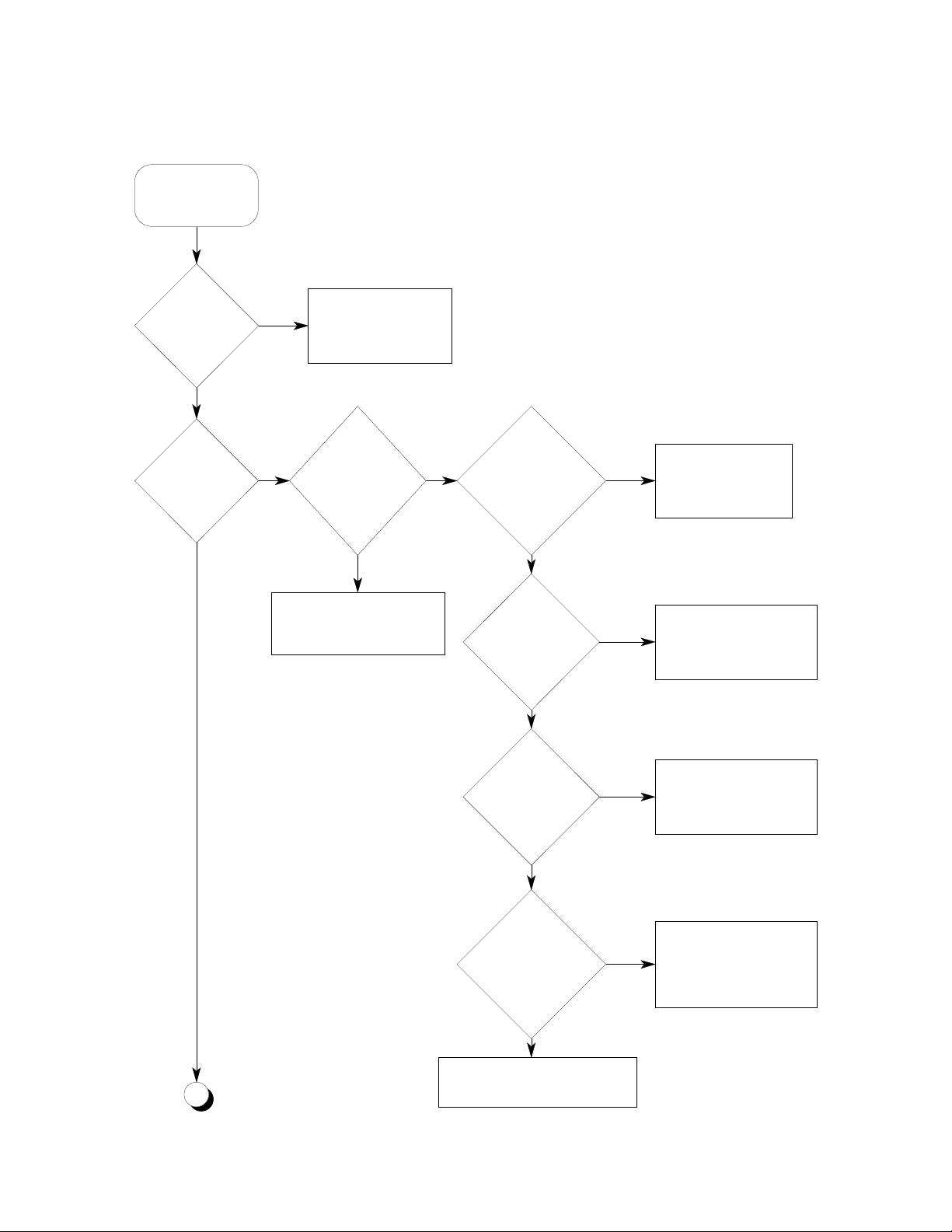
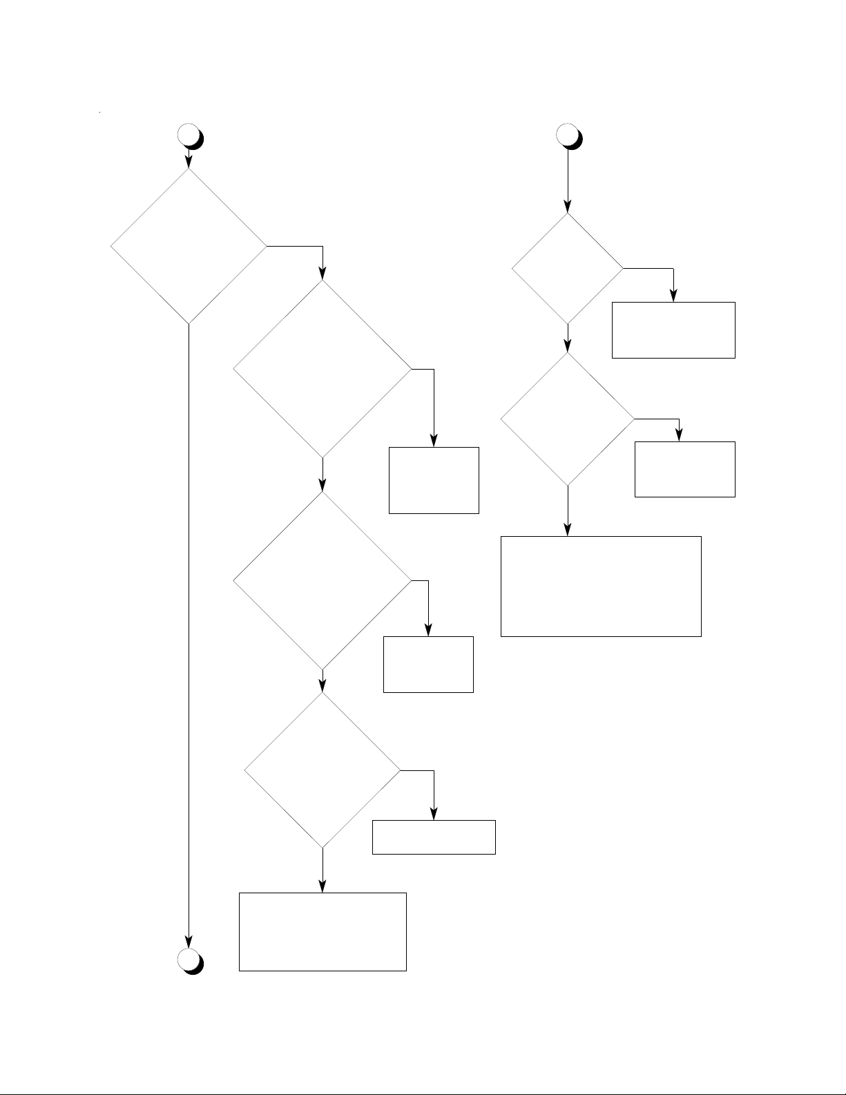
4.8 TROUBLESHOOTING FRYERS WITHOUT COMPUTERS
p
Fryer does no t
operate properly!
Is the fryer
filled with oil?
YES
Does the
POWER ON
indicator light?
YES
NO
NO
Refer to Chapter 2 for
proper filling and
operation of the fryer.
Is the Fryer
connected to building
power su pp l y?
NO
Connect fryer to building
power su pp l y as de sc r i bed i n
Chapter 1.
YES
Is the service
panel circuit
breaker tripped?
NO
Is the fire
protection tie in
system closed?
YES
YES
NO
Determine reason for
tripping. Reset the
circuit breaker.
Ensure that the fire
protection system is closed
or that the fire protection
oint is closed.
tie in
Is the control fuse
(F1) blown?
YES
Are the heating
elements down and is
the interlock
YES
working?
YES
Test the ON/OFF/TEST Switch
A
and repl ace i f ne ce s sa r y
NO
NO
Determine the cause for
blowing. Replace the fuse.
(Refer to 3.6)
Ensure the the heating
elemen t s are down. C h eck
the interlock switch per 4. 7
and replace if necessary.
4-7
Page 13
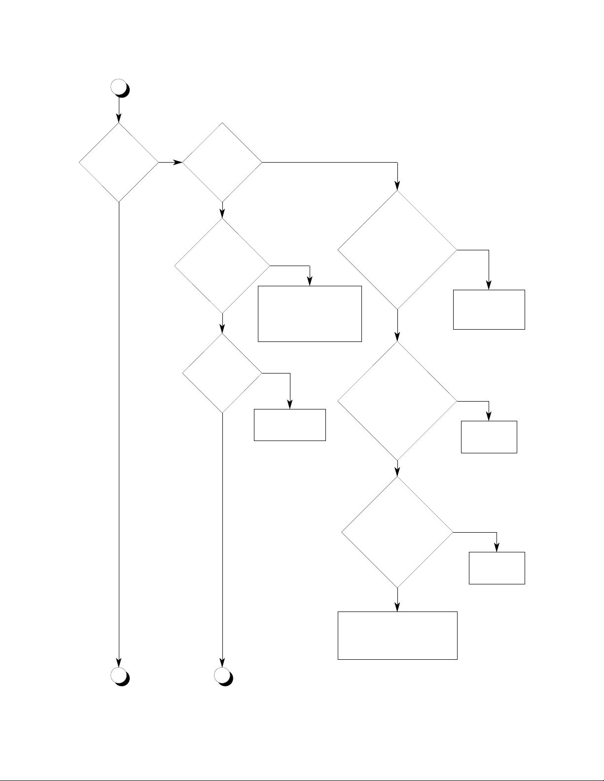
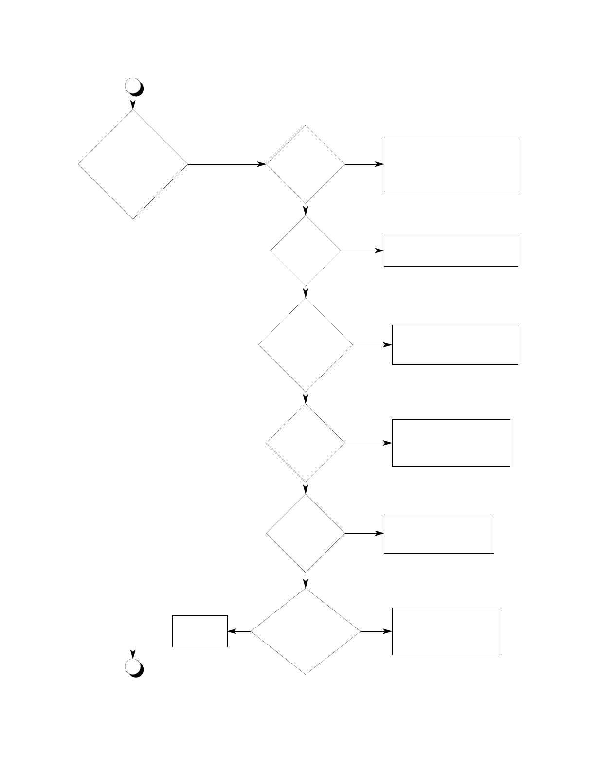
A
p
Does the fr y er
heat up?
YES
NO
Does the
HEATI NG l i ght
come on?
Are the heating
elements down and i s
the interlock
working?
Is the High Li mit
switch open?
YES
YES
NO
NO
Ensure that the heating
elements ar e dow n. C heck
the inter loc k s wi t ch per 4.7
and replace if neces s ary .
YES
Reset swit ch and
check tri p se t t i ng.
Test the temperature
probe as described in 4.6.
Is the temper at ure pr obe
defective?
NO
Test t he
temperature set
potentiom et er as descri bed in
4.4. Is t he potentionmeter
defective?
YES
Replace the
temperature
probe.
YES
Replace the
potentiometer
NO
Test the
NO
B
C
temperat ur e c ont rol
module as descri bed in
4.5. I s t he m odule
defective?
NO
Verify continuity of the leads
which provide 24 VAC pow er ,
and the potent iom eter and
robe signals to t he m odule.
YES
Replace the
module.
4-8
Page 14
B
C
YES
Does HEATING
light go out when
thermostat is set above
oil temperature?
YES
NO
Test the temperature
probe as described in 4.6.
Is the temperature probe
defective?
NO
Test the temperature
set potentiometer
as described in 4.4. Is
the potentionmeter
defective?
YES
Replace the
temperature
probe.
YES
Are heating
element fuses
blown?
NO
Check heating
elements as
described in 4.3.
Are they good?
YES
Check contactors K7 thru K10. Check
wiring for loose connections. Check
continuity between the grey lead on
each contactor and the grey lead to the
HEATING light .
YES
Replace the fuse(s)
and determine the
cause for blowing.
NO
Replace the
defective heating
elements
Replace the
NO
Test the
temperature control
module as described
in 4.5. Is the module
defective?
NO
Verify continuity of the leads
which provide 24 VAC power,
and the potentiometer and probe
D
signals to the module.
potentiometer.
YES
Replace the module.
4-9
Page 15
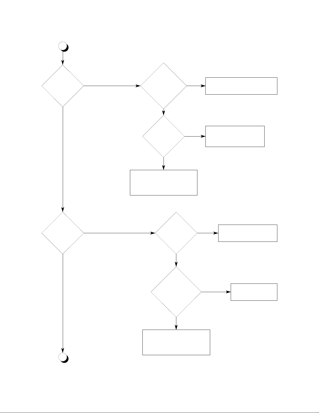
D
NO
Does HIGH LI MIT
switch t r i p dur i ng normal
operation?
NO
YES
Is solid
shortening being
melted?
NO
Is short ening
level too low?
NO
Is High Lim it
capillary tube
touching the heat i ng
elements?
NO
YES
YES
Ensure that short ening is packed
tightly ar ound heating elements !
Make sure t hat t he M el t Cyc le
switch is set to MELT ON.
Ensure that shortening level is f i ll ed
to the level mark.
YES
Gently m ove the capillar y t ube
away from the heating elem ent s
Are the heat i ng
elements dir ty?
NO
Is the t her mostat
set too high?
Test the
Replace the
module.
E
YES
temperature contr ol
module as described
in 4.5. I s the module
NO
defective?
YES
YES
NO
Perfor m a through cleaning of
the fry er as des cribed in 3.2.
Check the setting and
calibrati on of t he thermostat.
If the High Li m it s w it c h can
not be reset of cont i nues to
trip earl y replace the sw it c h.
4-10
Page 16
E
Does the
shortening get t oo
hot?
NO
Does the
shortening not get
hot enough?
YES
YES
Is the shortening
level too low?
NO
Is the t her mostat
set too high?
NO
Test t he temperat ur e pr obe as
described in 4. 6. Repl ace
temperat ure probe if def ec t iv e.
Is the thermost at
set too l ow?
YES
YES
Ensure that shortening level is f i ll ed
to the level mark.
Check the setting and
calibrati on of t he thermostat.
YES
Check the set ting and
calibration of the thermost at .
NO
Check heating
elements as
described in 4. 3. Are
NO
Test t he t emperatur e pr obe as
F
they all good?
YES
described in 4. 6. Replace the
temperature probe if defective.
NO
Replace the def ective
heating element s
4-11
Page 17
F
Does the f ryer
heat inter mi t t ent ly ?
NO
Does the f ryer
heat slowly ?
YES
Is the fryer
connected t o t he
proper vol tage su pply and
is it connected
properly?
NO
Fryer i s function i ng
NO
YES
properly.
Test the tem per a t ure
probe as described in 4. 6.
Is the temper ature pr obe
defective?
NO
Test the tem per a t ure
set pot ent i o m et e r a s
described in 4. 4. Is the
potentionmeter defecti ve?
NO
Test the
temper at ure contr ol
module as desc ribed in
4.5. I s t he modu le
defective?
NO
YES
YES
Replace the
temperature
probe.
YES
Replace t he
potentiometer.
Replace the
tempera t ure contr ol
module.
YES
Are the heat ing
elements c l ean?
YES
G
Correct t he inst all at ion.
NO
Perfor m a weekly cl eanin g
of the fr yer ( 3.2 )
Check heati ng el em e nt s as
described in 4.3. Rep lac e
heating elements if necessar y.
4-12
Page 18

G
Are any of t h e
heating el ements
fuses blo w n?
NO
Check heat i ng
elements as described
in 4.3. Ar e t hey all
good?
YES
Is the
temper at ur e pr obe l oos e
or in the wrong
location?
YES
NO
Replace the bl own f uses .
Replace the def e ct iv e
heating elem ents
YES
Move or tight en t he
probe.
NO
Check cont a ctors K 7 thru K 10. Check
wiring f or loos e connec t ion s. Check
Continui ty between the g r ey l ead on
each contactor and t he gr ey le ad t o
the HEATIN G light .
4-13
Page 19

4.9 TROUBLESHOOTING FRYERS WITH COMPUTERS
Fryer power is ON, but
the fryer is not functioning
properly.
Is the
computer panel
lit?
YES
Does the
computer display
indicate LOW after
allowing for sufficient time
for the fryer to
warm up?
NO
service panel circuit
breaker for the fryer
Close the breaker.
Is the
ON?
NO
Has temperature
control transfered to the
back-up thermostat? This can
be checked by moving the back-up
thermostat and watching the
heating light cycle
on and off.
YES YES
Check interconnecting wire betw een
computer and computer supply fuse (F3).
Is control fuse
supply fuse (F3)
(F1) open
NO
Is computer
open
NO
NO
YES
Are the
heating elements
properly seated in
the fryer tank?
Replace F1.
Replace F3.
Ensure that
the heating
NOYES
elements are
seated in the
tank.
YES
YES
Temperature control transfers
automatically to the Back-Up
thermostat when there is a problem
with the computer or power is lost to
the transfer relay.
A
Is the High Limit
switch tripped?
NO
CB
Reset the High
Limit Switch. If
YES
the switch will
not reset,
replace the
switch
4-14
Page 20

A CB
Does the
computer displ a y
indicate
PROB?
YES
Is the oil
temperat ure less
than 70°F?
NO
Is the pr obe
resist ance c or r ect?
Refer to 4.6 for pr obe
test proc edur e.
NO
YES
NO
Computer
functioning pr operly
for t em per at ure
control.
Raise the t em perature of
the oil using t he back up
thermostat. T he pr oblem
should correct itself.
Replace the
probe.
Check
element f uses .
Are any of the
fuses open?
NO
Check the
contactor s as
described in 4. 2. A r e
the contactors
defective?
NO
Perform elem ent
resistanc e c heck
asdescribed in 4- 3.
Determi ne why
YES
fuses blew and
replace the blow n
YES
fuses.
Replace the
defective
contactor.
YES
Check
interconnecting
wire.
If t he f y er has a
Blanch Mode Swich
ensure that it is in BLAN CH
OFF. Is the switch in
BLANCH OFF?
NO
But Blanch M ode
switch in BLANCH
OFF.
YES
Check
interconnect ing wi re.
4-15
Page 21

4.10 TROUBLESHOOTING BASKET LIFT PROBLEMS
Fryer works (115 VAC
presen t at fr y er) but
automatic basket lifts do
not function properly.
Does either
basket l ift
work?
YES
NO
Check the basket lift linkage and ensure
that it is not binding. Replace the basket
lift motor if the linkage is OK.
Check the
inter c on ne cting wi re
betwee n the ti mer ( o r
computer) and the basket
lift motors. Are all
connections
good?
YES
NO
Repair as
necessary.
Does
affected basket
lift lower/
raise?
YES
Does
basket lift run
continually?
YES
NO
Check for continuity between
the common and NO terminals
of the timer while pressing the
time start button. Is there
continuity?
YES
Check f or cont i n ui t y
between the NO terminal of
the timer and the NC
terminal of the roller
microswitch. Is there
continuity?
YES
Check continuity between the NC and
common terminal (White) of the microswitch.
There should be continuity when the switch is
released. Does the switch open and close?
YES
NO
NO
Repair wire
connectors.
NO
Replace
the timer.
and/or
Replac e t h e
microswitch.
Check the alignment of the microswit ch. The
switch should be aligned so that it is not
depressed when the basket lift is up and
depressed when the lift is down. If t he
switch cannot be aligned, replace the switch.
A
4-16
Page 22

A
NO
Does
basket lif t m ake
grinding no i ses a s
it cycles?
NO
Basket lift is f un ct i oning
properly.
Check the li nkag e to ens ur e t hat
YES
it is not binding. Level the fryer
and adjust t he bas ket hanger s t o
ensure compl et e cle aran ce.
4-17
Page 23

4.11 TROUBLESHOOTING BUILT-IN FILTER UNITS
Filter unit is not
working proper ly.
Is the
pump
running?
YES
Is oil
flowing?
YES
Oil pumping
slowly?
YES
NO
Turn the filter power switch
tripping and reset the circuit
NO
Is the filter
circuit breaker
tripped?
YES
off. Correct the cause for
breaker.
Is filter
pickup connected to
motor?
NO
Connect hose.
Is filter
pickup completely
connected?
NO
Conect hose.
NO
YES
YESNO
Is filter
motor overload
tripped
YES
Allow the motor to
cool, reset the
thermal overload on
the motor.
Check for solidified
shortening in internal lines.
Use the filter heaters for 5
to 15 minutes to liquify the
solids.
Is filter paper,
bag, or pickup screens
clogged?
Clean the screen or
replace filter media.
YES
NO
power supply wired
NO
Is 120 VAC
YES
in to the TB4
terminal.
NO
Wire in 120
VAC power
supply.
Check the refill time of the
pump with a new filter
installed. It should not exceed
1 minute for each 25 pounds
of shortening. See data plate
on fryer door for rating. The
pump may need replacement
if these times are exceeded
call service.
C
Do the filter
heaters work?
YES
NO
Is HEAT
light on with
heat switch in
HEAT?
YES
BA
NO
Is the
fryer plugged
in?
Plug in the
fryer.
4-18
NO
YES
Turn the filter power switch off.
Correct the cause for tripping
and reset the circuit breaker.
Is the filter
circuit breaker
tripped?
YES
NO
Check the
building
circuit
breaker.
Page 24

A
B
C
enough time for the heaters
resistance at the filter power cord
plug. If the resistance is higher
than 37.5 ohms, a heater has failed
Does the filter
circuit breaker keep
tripping?
Have you allowed
to warm-up?
YES
Use a VOM to measure the
and must be replaced.
Is the filter
correctly connected to
the filter piping?
NO
Allow 1/2 hour for the
filter heaters to
soften hardened
shortening.
YES
Reset the circuit
breaker and check
for a clogged filter
hose.
Replace the
switch.
NOYES
Replace filter
motor.
YES
NO
pump/heater switch when
YES
Is the
building circuit
breaker
open?
NO
Is there
continuity across
in ON
position?
YES
Is 115
VAC present at
the filter motor when
the filter switch
is ON?
NO
Does the filter
motor trip the
overload?
NO
D
Check the filter lines for
clogs.
Is the filter
correctly connected to
the filter piping?
YES
Check the filter lines for
clogs.
Ensure that the filter hose is
correctly connected to the filter unit
and the correct valves are open
NOYES
Ensure that teh filter hose is
correctly connected to the filter unit
and the correct valves are open
4-19
NO
Check switch and
replace if
defective.
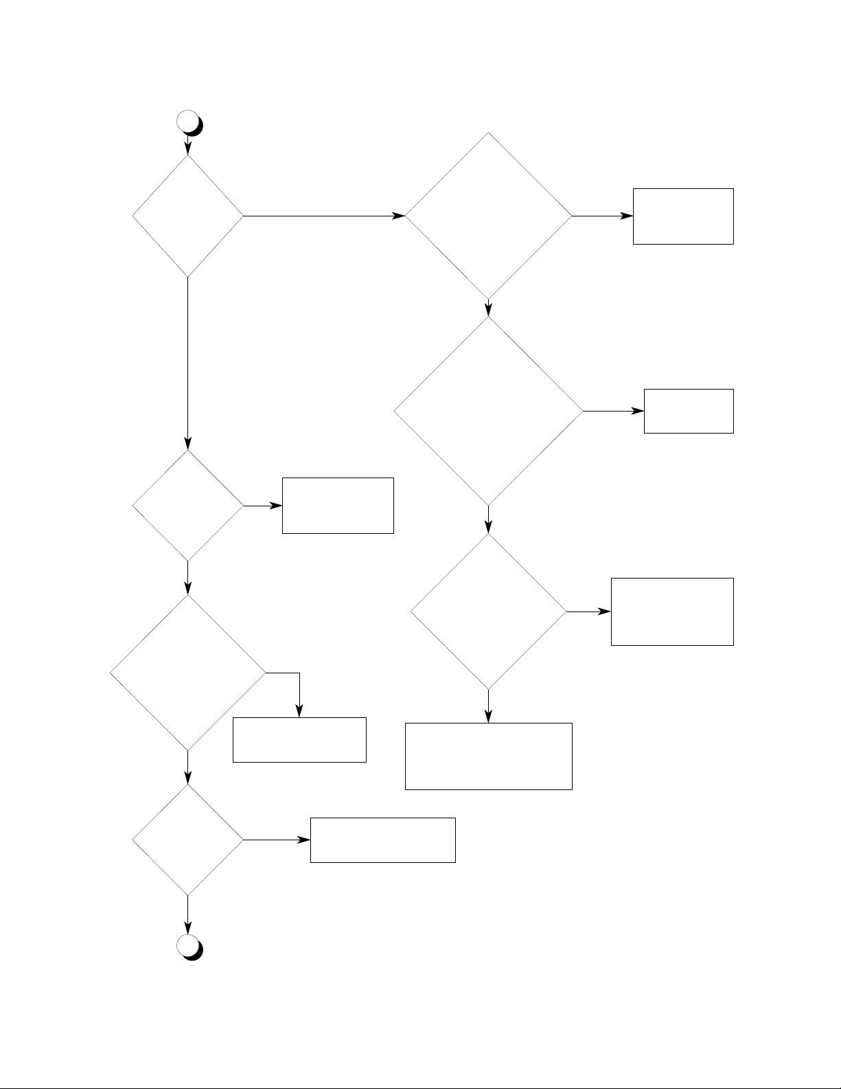
Page 25

g
D
Is pu mp runn i n g
slow, taking 4 to 5
minutes to f ill the
tank?
NO
Are the filter
heaters working?
YES
Clean out the filter lines. C heck the
current load on the filter motor. If it is
high replace the defective pum p.
Are a lot of air
bubbles coming out of
the oi l di sc harge
line?
NO
Is PAN HEAT
light ON?
NONO
YES
Is P17
connected?
Check a l l hose c o nn ection s
and the hose itself for leaks.
Correct any leaks or the hose
if damaged.
NO
Connect P 17
(Heater power)
YES
Filter unit is
working properly.
YES
Turn off the heaters and
check the resistance if the
heating element. If t he
resistance is significantly
reater or less than 72 ohms,
replace heater elements.
Check
interconnecting wire
between switch and
heater elements..
YES
4-20
YES
Is the
circuit breaker
open?
NO
Is there
continuity across
pump/heater switch
when in ON
position?
YES
NO
Reset the circuit
breaker and check
for clogged suction
line or quick
disconnect.
Replace the switch.
Page 26

4.12 TROUBLESHOOTING UFM FILTER UNITS
Filter unit is not
working properly.
Is the
pump
running?
YES
Is oil
flowing?
YES
Oil pumping
slowly?
YES
NO
Turn the filter power switch
tripping and reset the circuit
NO
Is the filter
circuit breaker
tripped?
YES
off. Correct the cause for
breaker.
Is filter
pickup attached
correctly?
NO
Connect hose.
Is filter
retun hose
completely connected?
NO
Conect hose.
NO
YES
Ensure return hose is engaged.
YESNO
Is filter
motor overload
tripped
YES
Allow the motor to
cool, reset the
thermal overload on
the motor.
Is the return
hose fully engaged
on filter fitting?
NO
Is filter paper,
bag, or pickup screens
clogged?
YES
Clean the screen or
replace filter media.
NO
supplied to TB4
YES
Is 120 VAC
terminal.
NO
Wire in 120
VAC power
supply.
Check for solidified shortening in
internal lines and check pick up
assembly screen. Wait until the
"PREHEAT FINISHED" light is
on before turning pump switch
"ON"
Check the refill time of the
pump with a new filter
installed. It should not exceed
the times listed in this manual.
NO
If the times are exceed have
the motor replaced. Use filter
aid to prevent fine foods from
blocking paper and causing
premature replacement.
YES
Check the
building
circuit
breaker
Does the
PREHEAT FINISHED
light come on?
YES
A
If the filter has had power removed for
more than 2 hours, it may take the heater
NO
10-12 minutes to turn the PREHEAT
FINISHED light on after power is
restored.
4-21
Page 27

A
Does the
filter leave
excessive oil in
the filter pan?
NO
Does the filter
circuit breaker keep
tripping?
YES
YES
least one system
valve open?
Scrape the filter layer down to the metal
scraping screen. Once the pan is empty,
tight en the pick up tube nut against t h e
sediment screen. Inspect th e filter bag for
tears and change if torn.
Is at
YES
NO
Is the
black hose fully
engaged?
NO
Solid shortening could be
blocking the pump discharge
YES
lines. Wait until the
PREHEAT FINISHED light is
on before turning the pump
switch ON.
NO
Does the filter
motor trip the
overload?
NO
Filt er unit is working
correctly.
Open the desire d valve first, then tur n
on the pump. S tarting t he pump before
opening a valve causes an overload
that opens the circuit breaker.
YES
Open the desired valve first, then
turn on the pump. Starting the
pump before ope ning a valve
causes an overload that opens the
Is at
least one system
valve open?
NO
circuit bre aker .
YES
Ensure that the
hose is fully
engaged on the
filter fitting.
Is the
black hose fully
engaged?
NO
Ensure that the
hose is fully
engaged on the
filter fitting.
Solid shortening could be
blocking the pump dis charge
lines. Wait until the PREHEAT
YES
FINISHED light is on before
turn ing the pump switc h ON. If
the filter has been tr ansfered to
another fryer allow the fryer to
operate for 45 minutes before
filtering.
4-22
Page 28

Chapter 5: Parts
This chapter contains listings of the components used in the different models of universal fryers.
These components are listed in two places, with the illustration and in ordered listings. The
illustrations in this chapter are provided to show relative location of components located in the fryer.
The fryer you have may not be illustrated in this chapter, but the part locations should be the same.
With each illustration there is a table of components in numerical order by illustration number. The
illustration has numbered lines pointing to components which are listed in the table.
At the end of this chapter there are alphabetical and numerical listings of all parts used in the universal
fryers. The alphabetical part list is arranged in alphabetical order according to the part name. Each
part name also has the Pitco Frialator part number. The numerical list is in Pitco Frialator part number
order. A brief description of each component is provided for each part.
5-1
Page 29

4 3
2
5
8
10
1
6
7
9
Index Index
Number Description Number Description
1 Basket Hanger
2 Basket
3 High Limit Cover
4 Interlock Switch Access Cover
5 Computer
6 Door Handle
7 Right Hand Door
8 Left Hand Door
9 Caster Set
10 UFM Filter Module (Optional)
Figure 5-1 Outside View
5-2
Page 30

7
8
6
5
4
3
2
1
Index Index
Number Description Number Description
1 Ground Lug
2 Terminal Block
3 Terminal Block
4 Fuses (6)
5 Fuse Block
6 Contactor, Mercury
7 Transformer
8 Receptacle
9 Contactor, Mechanical
10 Thermostat Knob
9
10
Figure 5-2 Entrance Box
5-3
Page 31

6
5
2
3
1
7
4
Index Index
Number Description Number Description
1 Auxiliary Thermostat Probe
2 Computer Probe Clamp
3 Computer Probe
4 Element Bottom Bar
5 Bracket Screens
6 Element Rack
7 High Limit Probe
8 High Limit Probe Clamp
9 Element
Figure 5-3 Inside Fryer Tank Components
5-4
Page 32

THIS PAGE INTENTIONALLY LEFT BLANK.
5-5
Page 33

Table 5-1 Frame-Cabinet / Electrical Assemblies With Components
Item Pitco Frialator Quantity
Number Part Number Description Per Unit
1 B7446005 Pan Liner #14 1
B7446006 Pan Liner #18 1
2 A6611401 Stop #14 1
A6611403 Stop #18 1
3 P5046980 Heater Strip 2
4 P6071448 Plug Hole 2" 1
5 A6613101 Cover, Side 1
6 A1819602 Bracket, Door Magnet 1
7 P6071300 Magnet 1
8 B3900101 Leg Set 1
9 B7402238 Bracket, Circuit Breaker 1
10 PP10104 Circuit Breaker 1
11 PP10082 Light, 125V Amber 1
12 PP10195 Screw, Button Head Hex 2
13 A6042801 Overlay 1
14 PP10375 Switch, Rocker 1
15 B3600202 Front Panel Weldment 1
16 B7230202 Hinge, Top Door 1
17 B2301208 Door #14 1
B2301210 Door #18 1
18 P6071516 Handle, Door 1
19 B7230302 Hinge, Bottom Door 1
20 P0075200 Screw, 2 #8 x 1/2 Self Drill 10
21 PP10686 Screw 6-32 x 1/4 2
22 PP10025 Screw 10-32 x 1/4 2
5-6
Revised 5/28/93
Page 34

Figure 5-4 Frame-Cabinet / Electrical Assemblies With Components
5-7
Page 35

Table 5-2 UFM Filter, Frame/Electrical Assembly
Item Pitco Frialator Quantity
Number Part Number Description Per Unit
1 B6621101 Filter Frame, Weldment 1
2 A6683002 Filter, Cover Motor 1
3 A6685702 Filter, Bracket Mounting Cover 1
4 A6684202 Filter, Cover Tubing 1
5 A6684502 Filter, Cover Tubing Cap 1
6 PP10741 Filter, QD SNP 23 Nipple 1
7 A6683802 Filter, Guard Tubing Channel 1
8 A6683102 Filter, Panel, Switch 1
9 PP10331 Lamp, 125V Green Rectangular 1
10 PP10735 Switch, Rocker DPST 15A, with Breaker 1
11 A6055801 Label, Overlay Filter Module 1
12 A7680402 Plate, Switch Pasta 1
13 A6683302 Filter, Box Electrical Body 1
14 P6071062 Caster, 2" With Top Plate 4
15 P0011300 Screw, 10-24 x 3/8" Indent Hex 16
16 PP10176 Nut, Center Lock 10-24 16
17 PP10147 Clip, Cable 0.375 ID 2
18 PP10107 Bushing, Strain Relief 1
19 B6717901 Wiring, Cord, Filter with Termination 1
20 P0093300 Nut, Hex (KEP) 1/4-20 ZN 5
21 A6682802 Filter, Guide CA 1
22 B6717101 Wiring, Cable Filter Assembly 1
23 PP10192 Bushing, Strain Relief 90 2
24 PP10460 Switch, Rocket Circuit Breaker SPST 8A 125V 1
25 PP10119 Label, Warning Motor Reset 1
26 P6071490 Plug, Hole 7/8" Plated 2
27 PP10692 Screw, 10-24 x 5/16" TH Phillips ZN 5
28 PP10752 Screw, 10-32 x 1/2" Thread Roller 18
29 P0000100 Screw, 6-32 x 7/8" RH ZN 2
30 P009100 Nut, Hex 6-32 ZN (KEP) 2
31 P0075200 Screw, TEK 2 #8 x 1/2" SLF DR 1
32 P6071497 Plug, Hole 3/4" Plated 1
33 B6622301 Hose Assembly With Quick Disconnect 1
5-8
Revised 5/28/93
Page 36

Figure 5-5 UFM Filter, Frame/Electrical Assembly
5-9
Page 37

Table 5-3 UFM Filter, Pick-Up/Pan Assembly
Item Pitco Frialator Quantity
Number Part Number Description Per Unit
1 B6621001 Filter Pan, Weldment 1
2 B6620001 Filter, Rack 1
3 B6617001 Filter, Screen Clip 1
4 B6621202 Filter, Catch Crumb, Weldment 1
5 A6056001 Label, Filter Instruction - Pan 1
6 B6621301 Filter, Cover Pan, Weldment 1
7 P6071516 Handle, Door, 3" C to C 1
8 A6681802 Filter, Coupling Top 1
9 B6615301 Filter, Screen Inlet 1
10 PP10409 O-Ring Viton 11/16" x .094" W 1
11 B6621601 Filter, Tube Suction, Weldment 1
12 PP10629 Ring, Retaining - Internal .875" 1
13 A6684601 Filter, Insulation Pick-Up 1
14 P0062100 Screw, 1/4-20 x 3/8" Set 2
15 P0007300 Screw, 8-32 x 1/4" Hex & N 2N 2
16 PP10613 Filter Paper, 18-1/2" x 20-1/2" Heavy Duty 1
Revised 5/28/93
5-10
Page 38

Figure 5-6 UFM Filter, Pick-Up/Pan Assembly
5-11
Page 39

Table 5-4 UFM Filter, Motor / Return Assembly
Item Pitco Frialator Quantity
Number Part Number Description Per Unit
1 PP10101 Pump/Motor 1/3 HP, 115/230V, 50/60Hz 1
2 PP10106 Fitting, Elbow Male 90 .50D x .5 NPT 2
3 A6682702 Filter, Tubing Out SS 1
4 PP10731 Fitting, Elbow Male 90 .50D x .375 NPT 1
5 B6621401 Filter, Tubing Pump - Inlet Weldment 1
6 PP10039 Heat Tape, 1/2" x 79" 110V 165 Watt 1
7 PP10111 O-Ring, Viton .50ID x .688 x .094W 2
8 A6685601 Filter, Insulator O-Ring Fitting 1
9 P0062100 Screw, 1/4-20 x 3/8" Set 1
10 B6717701 Wiring, Motor Harness 1
11 PP10739 Thermostat, Snap Disc 1
12 PP10687 Screw, 6-32 x 5/16" TH Phillips ZN 2
13 P009110 Nut, Hex (KEP) 6-32 ZN 2
14 PP10738 Nut, Retaining Clip 5/16" - 18 1
15 P0144000 Nut, Hex 5/16" - 18 SST 2
16 P0115000 Screw, 5/16" - 18 x 3/4" HHC SSBB 3
Revised 5/28/93
5-12
Page 40

Figure 5-7 UFM Filter, Motor / Return Assembly
5-13
Page 41

Table 5-5 Built-In Filter Pan With Components
Item Pitco Frialator Quantity
Number Part Number Description Per Unit
1 B6602001 Pan #14 1
B6602101 Pan #18 1
2 B6603001 Paper Retainer #14 1
B6603002 Paper Retainer #18 1
3 B6602401 Hose #14 1
B6602402 Hose #18 1
4 P6071123 Quick Disconnect, Male 1
5 P7037752-1 Elbow 90° 3/8 Street Plated 1
6 A6641802 Handle #14 2
A6641804 Handle #18 2
7 P6072611 Paper Support Rack #14 1
P6072612 Paper Support Rack #18 1
8 P7037316-1 Stand Pipe #14 1
P7037320-1 Stand Pipe #18 1
9 P7037675 Elbow 90° 3/8 Plated 1
Revised 5/28/93
5-14
Page 42

7
9
8
2
1
Figure 5-8 Built-In Filter Pan With Components
5-15
6
3
4
5
Page 43

Table 5-6 Built-In Filter Piping With Components
Item Pitco Frialator Quantity
Number Part Number Description Per Unit
1 P5046381 Pump and Motor 1
2 P6071530 Pump Only 1
3 P5046384 Motor Only 1
4 B7402241 Quick Disconnect 1
5 P0020600 Bolt 1/4 - 20 x 5/8" 4
6 P0080650 Washer, Flat 8
7 P0093300 Nut, Keep 4
Revised 5/28/93
5-16
Page 44

Figure 5-9 Built-In Filter Piping With Components
5-17
Page 45

Table 5-7 Built-In Filter With Accessories
Item Pitco Frialator Quantity
Number Part Number Description Per Unit
1 P5044768 Food Warmer, Built-In 1
P5044760 Food Warmer, Free Standing 1
2 P6072155 Drain Screen #14 1
P6072156 Drain Screen #18 1
3 A5811202 Pan Liner #14 1
A5811206 Pan Liner #18 1
4 PP10733 Filter Powder, 120, 8oz Packets
5 P6071371 Paper #14 Standard
PP10612 Paper #14 Heavy Duty
P6071373 Paper #18 Standard
PP10606 Paper #18 Heavy Duty
6 A1100802 Basket Hanger #14 1
A1100804 Basket Hanger #18 1
Revised 5/28/93
5-18
Page 46

Figure 5-10 Built-In Filter With Accessories
5-19
Page 47

ALPHABETICAL PART LIST
Models Pitco Frialator
Part Description Used on Part No.
BASKET HANGER, STAINLESS STEEL E14,E14B A1100406
BASKET HANGER, STAINLESS STEEL E18 A1100408
BASKET HANGER, STAINLESS STEEL E18B A1101002
CASTER (4/FILTER) ALL UFM P6071062
CASTER ASSEMBLY 7" WITH LOCKING DEVICE ALL UFM PP10811
CASTER ASSEMBLY 7" WITHOUT LOCKING DEVICE ALL UFM PP10810
CASTER WITH LOCK 6" ALL PP10809
CASTER WITHOUT LOCK 6" ALL PP10808
CHANNEL STRIP #14-2 E14 A1900104
CHANNEL STRIP #18-2 E14 A1900114
CIRCUIT BREAKER, 10 AMP ALL BIF PP10104
CIRCUIT BREAKER, 4 AMP, DOUBLE POLE 240V UFM PP10470
CLAMP, BAND (FILTER) ALL PP10034
CLEAN OUT ROD ALL A3301001
CLIP, SCREEN SF50,SF65 B6603601
CONTACTOR, DEFINITE PURPOSE, 40A, 24 V, 3PST-NO ALL PP10560
CONTACTOR, MERCURY-40AMP 24 VAC 5PST-NO ALL PP10553
CORD, PLUG-RETRACTILE 16-3 SJO E14,E18UFM PP10439
COUNTER BALANCE BEARING ASSEMBLY E14,E14B,
E18,E18B B7361701
COUNTER BALANCE HINGE BRACKET E14 B7361803
COUNTER BALANCE HINGE BRACKET E14B,E18 B7361804
COVER SCREWS ALL P0101200
CRUMB CATCH SF50,SF65 B6601802
CRUMB CATCH BASKET ALL BIF P6072165
CRUMB CATCH RETAINER E14 BIF B6601901
CRUMB CATCH RETAINER E18 BIF B6601902
DOOR HANDLE A LL P6071516
DOOR MAGNET ALL P6071300
DOOR, UNIVERSAL, STAINLESS STEEL OUTSIDE E14,E14B B2301205
DOOR, UNIVERSAL, STAINLESS STEEL OUTSIDE E18,E18B B2301206
DOOR, UNIVERSAL, STAINLESS STEEL OUTSIDE E12 B2301204
DRAIN OUTLET NIPPLE, 1-1/4" E14,E14B,
E18 A2502503
DRAIN VALVE E12 P6071769
DRAIN VALVE, 1-1/2" FULL PORT E18B P6071770
DRAIN VALVE, 1-1/4" STANDARD E14,E14B,
E18,E18B P6071785
ELEMENT HOUSING BOX COVER E14,E14B A2603206
ELEMENT HOUSING BOX COVER E18,E18B A2603208
ELEMENT RACK E12 B2800703-1
ELEMENT RACK E14B,E14 B2800706-1
ELEMENT RACK E18B B2800710-1
ELEMENT RACK E18 B2800708-1
5-20
Page 48

ALPHABETICAL PART LIST (Continued)
Models Pitco Frialator
Part Description Used on Part No.
ELEMENT RACK E14X B2800704-1
ELEMENT WIRES ALL SPECIAL
ORDER
ENTRANCE BOX COVER ALL A2900601
FAT CONTAINER ALL SPECIAL
ORDER
FEMALE QUICK DISCONNECT (BLACK DONUT) SF50,SF65 PP10113
FILTER CATCH, CRUMB, WELDMENT SF50A,SF65A B6621202
FILTER COVER, PAN, WELDMENT SF50A B6621301
FILTER COVER, PAN, WELDMENT SF65A B6621302
FILTER ENVELOPE 18" X 20-1/2" ALL UFM PP10613
FILTER HOSE UFM EXCEPT RPB SF50A,SF65A B6622001
FILTER HOSE UFM FOR RPB SF50A,SF65A B6622002
FILTER INSULATION PICK-UP SF50A,SF65A A6684601
FILTER INSULATOR TOP SF50A,SF65A A6685401
FILTER PAN, WELDMENT SF50A B6621001
FILTER PAN, WELDMENT SF65A B6621002
FILTER PAPER 13-1/2" X 24" E7-E14 BIF P6071371
FILTER PAPER 17-1/2" X 28" E18-E34 BIF P6071373
FILTER PAPER, HEAVY DUTY, 13-1/2" X 24" E7-E14 BIF PP10612
FILTER PAPER, HEAVY DUTY, 17-1/2" X 28" E18-E34 BIF PP10606
FILTER QD SNP 23 NIPPLE SF50A,SF65A PP10741
FILTER QUICK DISCONNECT ADAPTER SF50,SF65 B6603901
FILTER RACK SF50A,SF65A B6620001
FILTER RETURN INSULATION DISCONNECT SF50A,SF65A B6622801
FILTER SCREEN CLIP SF50A,SF65A B6617001
FILTER, TUBE SUCTION, COMPLETE SF50A,SF65A B6621701
FUSE 1 AMP SLOW BLOW GLASS ALL PP10122
FUSE 40 AMP E14,E14B,E18 P5045701
FUSE 50 AMP E18B P5045702
FUSE HOLDER ALL P5045792
GASKET, DRAIN LINE (SLEEVE) ALL PP10032
GASKET, DRAIN LINE (SLEEVE) ALL PP10032
GROUND CLAMP ALL P5045241
HANDLE, VALVE 3/8 BALL, COATED BLUE ALL PP10049
HANDLE, VALVE 3/8 BALL, COATED RED ALL PP10048
HANDLE, VALVE 3/8 BALL, COATED YELLOW A LL PP10050
HEAT TAPE, 1/2" X 79", 110 VAC, 165 W SF50,SF65 PP10039
HEAT TAPE, 110 VAC, 120 W SF50,SF65 PP10194
HEATER, SILICONE, 120 VAC, 250 W SF50,SF65 PP10099
HEATING ELEMENT E12-208V P5046923
HEATING ELEMENT E12-240V P5046924
HEATING ELEMENT E12-480V P5046951
HEATING ELEMENT E18-480V P5046900
5-21
Page 49

ALPHABETICAL PART LIST (Continued)
Models Pitco Frialator
Part Description Used on Part No.
HEATING ELEMENT E18-208V P5046901
HEATING ELEMENT E18-240V P5046902
HEATING ELEMENT E18B-208V P5046903
HEATING ELEMENT E18B-240V P5046904
HEATING ELEMENT E18B-480V P5046952
HEATING ELEMENT E14-208V P5046920
HEATING ELEMENT E14-240V P5046921
HEATING ELEMENT E14-480V P5046919
HEATING ELEMENT E14B,E7-208V P5046915
HEATING ELEMENT E14B,E7-240V P5046916
HEATING ELEMENT E14B,E7-480V P5046960
HIGH LIMIT BULB CLAMP ALL B7370402
HIGH LIMIT CAPILLARY CLAMP ALL A1400902
HIGH LIMIT COVER ALL B7370101
HIGH LIMIT SWITCH ALL P5047216
HINGE, DOOR-BOTTOM LH AL L B7230301
HINGE, DOOR-BOTTOM RH ALL B7230302
HINGE, DOOR-TOP LH ALL B7230201
HINGE, DOOR-TOP, RH ALL B7230202
HOSE ASSEMBLY WITH QUICK DISCONNECT SF50A,SF65A B6622301
INTERLOCK SWITCH ALL P5047170
INTERLOCK SWITCH COVER ALL A2601502
KNOB, 200-400 OFF ELECTRIC ALL PP10539
LAMP, 125 VAC AMBER RECTANGULAR ALL UFM PP10082
LAMP, 125 VAC GREEN RECTANGULAR SF50A,SF65A PP10331
LEG, ADJUSTABLE 6" ALL B3900909
LEG, ADJUSTABLE 8" ALL B7472909
LEG, ADJUSTABLE, 7" ALL B3900408
LOCK ARM TIP ALL P5045161
MODULE 1 PROD 14/18-184 NAT E14,E18 P5044851
MODULE 1 PROD 14/18-184 REBUILT E14,E18 P5044852
MODULE 1 PROD 7-184 NAT E7 P5044856
MODULE 1 PROD 7-184 REBUILT E7 P5044857
MODULE 8 PROD 14/18-884 NAT E14,E18 P5044850
MODULE 8 PROD 14/18-884 REBUILT E14,E18 P5044854
MODULE 8 PROD 7-884 NAT E7 P5044855
MODULE 8 PROD 7-884 REBUILT E7 P5044853
O-RING, VITON .50 ID X .688 X .094W SF50A, SF65A PP10111
PICKUP QUICK DISCONNECT, FEMALE, NO/RING SF50,SF65 P6071122
PICKUP QUICK DISCONNECT, MALE SF50,SF65 P6071123
PLUG - 9 POLE MALE ALL P5045826
PROBE STANDOFF CLAMP AL L B7370403
PUMP/MOTOR ASSEMBLY, 115/230 VAC ALL BIF P5046381
PUMP/MOTOR ASSEMBLY, 115/230 VAC, 60HZ, 1/3 HP ALL UFM PP10101
5-22
Page 50

ALPHABETICAL PART LIST (Continued)
Models Pitco Frialator
Part Description Used on Part No.
RECEPTACLE, 3 PRONG, 15A, 125VAC ALL UFM PP10103
RETURN HOSE NEW STYLE SF50 SF50 B6602803
RETURN HOSE NEW STYLE SF65 SF65 B6602804
SPRING ALL P6071636
SQUARE BASKETS, FINE MESH E12 P6072124
SQUARE BASKETS, FINE MESH E14,E14B P6072144
SQUARE BASKETS, FINE MESH E18 P6072187
SQUARE BASKETS, FINE MESH E12 P6072124
SQUARE BASKETS, REGULAR MESH E12 P6072123
SQUARE BASKETS, REGULAR MESH E14,E14B P6072143
SQUARE BASKETS, REGULAR MESH E18 P6072183
SUCTION TUBE SF50,SF65 B6603801
SUPPORT RACK, TOP SF50,SF65 B6603701
SWITCH , ROCKER, DPDT (ON-OFF-ON) SF50,SF65 PP10098
SWITCH, ROCKER CIRCUIT BREAKER SPST, 8A, 125 VAC SF50A,SF65A PP10460
SWITCH, ROCKER DPST 15A, WITH BREAKER SF50A,SF65A PP10735
TERMINAL BLOCK (TB2) ALL P5047305
TERMINAL BLOCK (TB3) ALL P5047303
THERMOSTAT KNOB ALL P6071270
THERMOSTAT PROBE E12,E14 ALL
E18 P6700602
THERMOSTAT, SNAP DISK SF50A,SF65A PP10739
TWIN BASKETS, FINE MESH E12 P6072126
TWIN BASKETS, FINE MESH E14,E14B P6072146
TWIN BASKETS, FINE MESH E18 P6072188
TWIN BASKETS, REGULAR MESH E12 P6072125
TWIN BASKETS, REGULAR MESH E14,E14B P6072145
TWIN BASKETS, REGULAR MESH E18 P6072184
VALVE, BALL 3/8" PLTD W/O HANDLE ALL P6071780
5-23
Page 51

NUMERICAL PART LIST
Pitco Frialator Models
Part No. Part Description Used on
A1100406 BASKET HANGER, STAINLESS STEEL E14,E14B
A1100408 BASKET HANGER, STAINLESS STEEL E18
A1101002 BASKET HANGER, STAINLESS STEEL E18B
A1400902 HIGH LIMIT CAPILLARY CLAMP ALL
A1900104 CHANNEL STRIP #14-2 E14
A1900114 CHANNEL STRIP #18-2 E14
A2502503 DRAIN OUTLET NIPPLE, 1-1/4" E14,E14B,E18
A2601502 INTERLOCK SWITCH COVER ALL
A2603206 ELEMENT HOUSING BOX COVER E14,E14B
A2603208 ELEMENT HOUSING BOX COVER E18,E18B
A2900601 ENTRANCE BOX COVER ALL
A3301001 CLEAN OUT ROD ALL
A6684601 FILTER INSULATION PICK-UP SF50A,SF65A
A6685401 FILTER INSULATOR TOP SF50A,SF65A
B2301204 DOOR, UNIVERSAL, STAINLESS STEEL OUTSIDE E12
B2301205 DOOR, UNIVERSAL, STAINLESS STEEL OUTSIDE E14,E14B
B2301206 DOOR, UNIVERSAL, STAINLESS STEEL OUTSIDE E18,E18B
B2800703-1 ELEMENT RACK E12
B2800704-1 ELEMENT RACK E14X
B2800706-1 ELEMENT RACK E14B,E14
B2800708-1 ELEMENT RACK E18
B2800710-1 ELEMENT RACK E18B
B3900408 LEG, ADJUSTABLE, 7" ALL
B3900909 LEG, ADJUSTABLE 6" ALL
B6601802 CRUMB CATCH SF50,SF65
B6601901 CRUMB CATCH RETAINER E14 BIF
B6601902 CRUMB CATCH RETAINER E18 BIF
B6602803 RETURN HOSE NEW STYLE SF50 SF50
B6602804 RETURN HOSE NEW STYLE SF65 SF65
B6603601 CLIP, SCREEN SF50,SF65
B6603701 SUPPORT RACK, TOP SF50,SF65
B6603801 SUCTION TUBE SF50,SF65
B6603901 FILTER QUICK DISCONNECT ADAPTER SF50,SF65
B6617001 FILTER SCREEN CLIP SF50A,SF65A
B6620001 FILTER RACK SF50A,SF65A
B6621001 FILTER PAN, WELDMENT SF50A
B6621002 FILTER PAN, WELDMENT SF65A
B6621202 FILTER CATCH, CRUMB, WELDMENT SF50A,SF65A
B6621301 FILTER COVER, PAN, WELDMENT SF50A
B6621302 FILTER COVER, PAN, WELDMENT SF65A
B6621701 FILTER, TUBE SUCTION, COMPLETE SF50A,SF65A
B6622001 FILTER HOSE UFM EXCEPT RPB SF50A,SF65A
B6622002 FILTER HOSE UFM FOR RPB SF50A,SF65A
5-24
Page 52

NUMERICAL PART LIST (Continued)
Pitco Frialator Models
Part No. Part Description Used on
B6622301 HOSE ASSEMBLY WITH QUICK DISCONNECT SF50A,SF65A
B6622801 FILTER RETURN INSULATION DISCONNECT SF50A,SF65A
B7230201 HINGE, DOOR-TOP LH ALL
B7230202 HINGE, DOOR-TOP, RH ALL
B7230301 HINGE, DOOR-BOTTOM LH ALL
B7230302 HINGE, DOOR-BOTTOM RH ALL
B7361701 COUNTER BALANCE BEARING ASSEMBLY E14,E14B,
E18,E18B
B7361803 COUNTER BALANCE HINGE BRACKET E14
B7361804 COUNTER BALANCE HINGE BRACKET E14B,E18
B7370101 HIGH LIMIT COVER ALL
B7370402 HIGH LIMIT BULB CLAMP ALL
B7370403 PROBE STANDOFF CLAMP ALL
B7472909 LEG, ADJUSTABLE 8" ALL
P0101200 COVER SCREWS ALL
P5044850 MODULE 8 PROD 14/18-884 NAT E14,E18
P5044851 MODULE 1 PROD 14/18-184 NAT E14,E18
P5044852 MODULE 1 PROD 14/18-184 REBUILT E14,E18
P5044853 MODULE 8 PROD 7-884 REBUILT E7
P5044854 MODULE 8 PROD 14/18-884 REBUILT 14,18
P5044855 MODULE 8 PROD 7-884 NAT E7
P5044856 MODULE 1 PROD 7-184 NAT E7
P5044857 MODULE 1 PROD 7-184 REBUILT E7
P5045161 LOCK ARM TIP ALL
P5045241 GROUND CLAMP ALL
P5045701 FUSE 40 AMP E14,E14B,E18
P5045702 FUSE 50 AMP E18B
P5045792 FUSE HOLDER ALL
P5045826 PLUG - 9 POLE MALE ALL
P5046381 PUMP/MOTOR ASSEMBLY, 115/230 VAC ALL BIF
P5046900 HEATING ELEMENT E18-480V
P5046901 HEATING ELEMENT E18-208V
P5046902 HEATING ELEMENT E18-240V
P5046903 HEATING ELEMENT E18B-208V
P5046904 HEATING ELEMENT E18B-240V
P5046915 HEATING ELEMENT E14B,E7-208V
P5046916 HEATING ELEMENT E14B,E7-240V
P5046919 HEATING ELEMENT E14-480V
P5046920 HEATING ELEMENT E14-208V
P5046921 HEATING ELEMENT E14-240V
P5046923 HEATING ELEMENT E12-208V
P5046924 HEATING ELEMENT E12-240V
P5046951 HEATING ELEMENT E12-480V
P5046952 HEATING ELEMENT E18B-480V
5-25
Page 53

NUMERICAL PART LIST (Continued)
Pitco Frialator Models
Part No. Part Description Used on
P5046960 HEATING ELEMENT E14B,E7-480V
P5047170 INTERLOCK SWITCH ALL
P5047216 HIGH LIMIT SWITCH ALL
P5047303 TERMINAL BLOCK (TB3) ALL
P5047305 TERMINAL BLOCK (TB2) ALL
P6071062 CASTER (4/FILTER) ALL UFM
P6071122 PICKUP QUICK DISCONNECT, FEMALE, NO/RING SF50,SF65
P6071123 PICKUP QUICK DISCONNECT, MALE SF50,SF65
P6071270 THERMOSTAT KNOB ALL
P6071300 DOOR MAGNET ALL
P6071371 FILTER PAPER 13-1/2" X 24" E7-E14 BIF
P6071373 FILTER PAPER 17-1/2" X 28" E18-E34 BIF
P6071516 DOOR HANDLE ALL
P6071636 SPRING ALL
P6071769 DRAIN VALVE E12
P6071770 DRAIN VALVE, 1-1/2" FULL PORT E18B
P6071780 VALVE, BALL 3/8" PLTD W/O HANDLE ALL
P6071785 DRAIN VALVE, 1-1/4" STANDARD E14,E14B,
E18,E18B
P6072123 SQUARE BASKETS, REGULAR MESH E12
P6072124 SQUARE BASKETS, FINE MESH E12
P6072124 SQUARE BASKETS, FINE MESH E12
P6072125 TWIN BASKETS, REGULAR MESH E12
P6072126 TWIN BASKETS, FINE MESH E12
P6072143 SQUARE BASKETS, REGULAR MESH E14,E14B
P6072144 SQUARE BASKETS, FINE MESH E14,E14B
P6072145 TWIN BASKETS, REGULAR MESH E14,E14B
P6072146 TWIN BASKETS, FINE MESH E14,E14B
P6072165 CRUMB CATCH BASKET ALL BIF
P6072183 SQUARE BASKETS, REGULAR MESH E18
P6072184 TWIN BASKETS, REGULAR MESH E18
P6072187 SQUARE BASKETS, FINE MESH E18
P6072188 TWIN BASKETS, FINE MESH E18
P6700602 THERMOSTAT PROBE E12,E14
ALL,E18
PP10032 GASKET, DRAIN LINE (SLEEVE) ALL
PP10032 GASKET, DRAIN LINE (SLEEVE) ALL
PP10034 CLAMP, BAND (FILTER) ALL
PP10039 HEAT TAPE, 1/2" X 79", 110 VAC, 165 W SF50,SF65
PP10048 HANDLE, VALVE 3/8 BALL, COATED RED ALL
PP10049 HANDLE, VALVE 3/8 BALL, COATED BLUE ALL
PP10050 HANDLE, VALVE 3/8 BALL, COATED YELLOW ALL
PP10082 LAMP, 125 VAC AMBER RECTANGULAR ALL UFM
PP10098 SWITCH , ROCKER, DPDT (ON-OFF-ON) SF50,SF65
5-26
Page 54

NUMERICAL PART LIST (Continued)
Pitco Frialator Models
Part No. Part Description Used on
PP10099 HEATER, SILICONE, 120 VAC, 250 W SF50,SF65
PP10101 PUMP/MOTOR ASSEMBLY, 115/230 VAC, 60HZ, 1/3 HP ALL UFM
PP10103 RECEPTACLE, 3 PRONG, 15A, 125VAC ALL UFM
PP10104 CIRCUIT BREAKER, 10 AMP ALL BIF
PP10111 O-RING, VITON .50 ID X .688 X .094W SF50A, SF65A
PP10113 FEMALE QUICK DISCONNECT (BLACK DONUT) SF50,SF65
PP10122 FUSE 1 AMP SLOW BLOW GLASS ALL
PP10194 HEAT TAPE, 110 VAC, 120 W SF50,SF65
PP10331 LAMP, 125 VAC GREEN RECTANGULAR SF50A,SF65A
PP10439 CORD, PLUG-RETRACTILE 16-3 SJO 14,18UFM
PP10460 SWITCH, ROCKER CIRCUIT BREAKER SPST, 8A, 125 VAC SF50A,SF65A
PP10470 CIRCUIT BREAKER, 4 AMP, DOUBLE POLE 240V UFM
PP10539 KNOB, 200-400 OFF ELECTRIC A LL
PP10553 CONTACTOR, MERCURY-40AMP 24 VAC 5PST-NO ALL
PP10560 CONTACTOR, DEFINITE PURPOSE 40AMP 24 VAC 3PST-NO ALL
PP10606 FILTER PAPER, HEAVY DUTY, 17-1/2" X 28" E18-E34 BIF
PP10612 FILTER PAPER, HEAVY DUTY, 13-1/2" X 24" E7-E14 BIF
PP10613 FILTER ENVELOPE 18" X 20-1/2" ALL UFM
PP10735 SWITCH, ROCKER DPST 15A, WITH BREAKER SF50A,SF65A
PP10739 THERMOSTAT, SNAP DISK SF50A,SF65A
PP10741 FILTER QD SNP 23 NIPPLE SF50A,SF65A
PP10808 CASTER WITHOUT LOCK 6" ALL
PP10809 CASTER WITH LOCK 6" ALL
PP10810 CASTER ASSEMBLY 7" WITHOUT LOCKING DEVICE ALL UFM
PP10811 CASTER ASSEMBLY 7" WITH LOCKING DEVICE ALL UFM
SPECIAL ORDER ELEMENT WIRES ALL
SPECIAL ORDER FAT CONTAINER ALL
5-27
Page 55

5-28
Page 56

In the event of problems with or questions about you
order, please contact the Pitco Frialator factory, from
8:00 a.m. - 5:00 p.m., Eastern Standard Time, Monday through Friday:
(603)225-6684 World Wide
L20-055 R12 (06/11)
In the event of problems with or questions about you
equipment, please contact the Pitco Frialator Authorized Service and Parts representative (ASAP) covering your area, through the National Service Network
at: (603)-225-6684 24 hours
 Loading...