

Page 1
There's Always Something Cooking!
Installation, Operation, and Maintenance Manual
For Food, Donut, Chicken, and Fish Fryers
Covering Models
20, 24, 26, and 34
R
R
APPR OVE D
R
Page 2

MTS # PF17-01 Pitco Frialator #L20-078 Revision 3 Rev. Date 09/09/96
Page 3
NOTICES
There are three different types of notices that you should be familiar with, a NOTICE, CAUTION,
and WARNING. A NOTICE is a special note used to call attention to a particularly important point.
CAUTION is used to point out a procedure or operation which may cause equipment damage. The
WARNING notice is the most important of the three because it warns of an operation that may cause
personal injury. Please familiarize yourself with your new cooker before operating it and heed the
notices throughout this manual. The WARNINGS are listed below and on the following page for
your review prior to operating the unit.
FOR YOUR SAFETY
DO NOT store or use gasoline or other flammable
vapors or liquids in the vicinity of this or any other
appliance.
WARNING: Improper installation, adjustment, alteration, service or maintenance can cause property damage, injury or death. Read the installation, operating
and maintenance instructions thoroughly before installing or servicing this equipment.
TO THE PURCHASER
POST IN A PROMINENT LOCATION INSTRUCTIONS TO
BE FOLLOWED IN THE EVENT THAT AN OPERATOR
SMELLS GAS. OBTAIN THIS INFORMATION FROM YOUR
LOCAL GAS SUPPLIER.
THIS MANUAL MUST BE RETAINED FOR FUTURE REFERENCE
Page 4
SAFETY SAFETY SAFETY SAFETY SAFETY
WARNING
The fryer may be equipped with an oil proof, electrical supply cord with a
three prong safety plug. This is to protect operators from electrical shock
hazard in the event of an equipment malfunction. DO NOT cut or remove the
grounding (third) prong from this plug.
WARNING
There is an open flame inside the fryer. The unit may get hot enough to set
near by materials on fire. Keep the area around the fryer free from combustibles.
WARNING
NEVER supply the fryer with a gas that is not indicated on the data plate.
Using the incorrect gas type will cause improper operation. If you need to
convert the fryer to another type of fuel, contact your dealer.
WARNING
DO NOT use an open flame to check for gas leaks!
WARNING
Wait 5 minutes before attempting to relight the pilot to allow for any gas in
the fryer to dissipate.
WARNING
Never melt blocks of shortening on top of the burner tubes. This will cause
a fire, and void your warranty.
WARNING
Water and shortening DO NOT mix. Keep liquids away from hot shortening.
Dropping liquid frozen food into the hot shortening will cause violent boiling.
WARNING
At operating temperature the shortening temperature will be greater than
300°F. Do not attempt to move the appliance when the oil is at operating
temperature. The hot oil WILL cause injury to you when it comes in contact
with your skin.
SAFETY SAFETY SAFETY SAFETY SAFETY
Page 5
SAFETY SAFETY SAFETY SAFETY SAFETY
WARNING
Ensure that the fryer can get enough air to keep the flame burning correctly.
If the flame is starved for air it can give of a dangerous carbon monoxide gas.
Carbon Monoxide is a clear odorless gas that can cause suffocation.
WARNING
If your appliance operates on line voltage, the power supply must be
disconnected before servicing or cleaning the appliance.
WARNING
The fryer must be properly restrained to prevent movement or tipping. This
restraint must prevent the fryer from movements that would splash hot liquids
on personnel. This restraint may be by any means (alcove installation,
adequate ties, or battery installation).
SAFETY SAFETY SAFETY SAFETY SAFETY
Page 6

Table of Contents
Section Title Page
Safety Notice
Table of Contents ........................................................................................................................ i-ii
List of Tables and Figures .............................................................................................................. iii
Chapter 1: General Information and Installation .................................................................. 1-1
1.1 WHICH FRYER DO I HAVE? ................................................................................ 1-1
1.2 CHECKING YOUR NEW FRYER ......................................................................... 1-1
1.3 ASSEMBLY AND LEVELING .............................................................................. 1-2
1.3.1 Leg Installation and Adjustment ........................................................................... 1-2
1.3.2 Heat Deflector Installation .................................................................................... 1-2
1.3.3 Splashback Installation ......................................................................................... 1-3
1.3.4 Flue Installation .................................................................................................... 1-3
1.3.5 Drainboard Installation ......................................................................................... 1-3
1.4 INSTALLATION ..................................................................................................... 1-3
1.4.1 Installation Clearances .......................................................................................... 1-4
1.4.2 Gas Connection .................................................................................................... 1-4
1.4.2.1 Fuel Types ..................................................................................................... 1-4
1.4.2.2 Fuel Supply Line Leak and Pressure Testing ................................................. 1-5
1.4.2.3 Gas Line Connection ..................................................................................... 1-5
1.4.3 Electrical Connection ........................................................................................... 1-5
1.4.4 Ventilation and Fire Safety Systems ..................................................................... 1-6
1.5 INITIAL ADJUSTMENTS ...................................................................................... 1-7
1.5.1 Visual Checks ...................................................................................................... 1-7
1.5.2 Burner Ignition Systems ....................................................................................... 1-8
1.5.2.1 Lighting Instructions for Manual Pilot Lights ................................................. 1-8
1.5.2.1.1 Pilot Flame Adjustment ............................................................................ 1-9
1.5.2.2 Electronic Ignition Pilot Systems .................................................................. 1-10
1.5.2.2.1 Electronic Ignition Pilot Flame Adjustment ............................................ 1-10
1.5.3 Main Burner System .......................................................................................... 1-11
1.5.3.1 Gas Line Requirements ................................................................................ 1-12
1.5.3.2 Burner Adjustment ....................................................................................... 1-12
1.5.4 Initial Cleaning ................................................................................................... 1-13
1.5.5 Thermostat Calibration Check (Standard) .......................................................... 1-14
1.5.6 Thermostat Calibration ....................................................................................... 1-15
1.5.7 Thermostat Calibration (Solid State) .................................................................. 1-15
i
Page 7

Table of Contents (Continued)
Section Title Page
Chapter 2: Operating Instructions .......................................................................................... 2-1
2.1 FILLING THE FRYER ............................................................................................ 2-1
2.1.1 Filling the Fryer With Liquid Shortening ............................................................. 2-1
2.1.2 Filling the Fryer With Solid Shortening ............................................................... 2-1
2.2 OPERATING INSTRUCTIONS ............................................................................. 2-2
2.2.1 Fryer Start-Up ...................................................................................................... 2-2
2.2.2 Fryer Shutdown ................................................................................................... 2-2
2.2.3 Power Failure ....................................................................................................... 2-3
2.3 DAILY CLEANING ................................................................................................ 2-3
CHAPTER 3: Owner Maintenance and Adjustments .......................................................... 3-1
3.1 WEEKLY FRYER CLEANING (BOIL OUT) ....................................................... 3-1
3.2 FRYER TROUBLESHOOTING ............................................................................. 3-3
ii
Page 8

List of Tables and Figures
Table Title Page
1-1 Ventilation and Fire Safety References ...................................................................... 1-6
Figure Title Page
1-1 Pilot Assembly, Flame Adjustment ............................................................................ 1-9
1-2 Main Burner Conditions ........................................................................................... 1-11
1-3 Typical Gas Valve Showing Location of Pressure Regulator and Pilot Adjusters ... 1-12
1-4 Air Collar ............................................................................................................... 1-13
iii
Page 9

iv
Page 10

Chapter 1: General Information and Installation
Congratulations on the purchase of your new Pitco Frialator universal fryer. This unit will give you
many years of reliable service if you follow the simple operation and maintenance procedures in this
manual. Contained in this manual are the general installation, operation, and maintenance
procedures for the universal fryer Models 20, 24, 26 & 34.
1.1 WHICH FRYER DO I HAVE?
There are many models and options available for the gas fryer, each with its own model number. To
find out which model you have, look inside the door at the equipment identification plate. This plate
has a lot of useful information. The model number identifies which fryer and what features you have.
A brief description of each model and its features in Table 1-1.
Table 1-1 Fryer Model Information
Model
Number
20 These large capacity fryers are designed to provide
large amounts of fried foods, fish, chicken, etc.
These fryers give top quality batch after batch
because they incorporate exclusive features that
eliminate product damage or sogginess. Each
model can be equipped with a varity of options
24 Frying Area: 24" X 24"
26 Frying Area: 18" X 26"
Description Features
Frying Area: 20" X 20"
Oil Capacity: 100 Lbs
48.8 Liters
Gas Consumption:
60,000 BTU
15,120 KCal
Oil Capacity: 150 Lbs
73.4 Liters
Gas Consumption:
120,000 BTU
30,240 KCal
Oil Capacity: 120 Lbs
58.7 Liters
Gas Consumption:
80,000 BTU
20,160 KCal
34 Frying Area:24" X 34"
Oil Capacity: 210 Lbs
102.6 Liters
Gas Consumption:
110,000 BTU
27,720 KCal
1-1
Page 11
1.2 CHECKING YOUR NEW FRYER
Your new fryer has been carefully packed into a crate. Every effort has been made to ensure that your
fryer will be delivered to you in perfect condition. As you unpack your new fryer, inspect each of
the pieces for damage. If something is damaged, DO NOT sign the bill of lading. Contact the shipper
immediately, because the shipper is only responsible for 15 days after delivery. Check the packing
list enclosed with your fryer to ensure that you have received all of the parts to the fryer. If you are
missing any parts, contact the dealer from whom the fryer was purchased. As you unpack the fryer
and it's accessories be careful to keep the weight of the fryer evenly distributed.
Flue Vents
CAUTION
To prevent equipment damage, don't tilt the fryer onto
any two of it's legs or pull the unit by the flue vents.
XX
Locate your Pitco Frialator warranty and fill in the serial number of the fryer and the date received.
You will find the serial number on the plate inside the door. Put your warranty sheet in a safe place
for future reference. DO NOT return the sheet to Pitco Frialator.
1.3 ASSEMBLY AND LEVELING
When you receive your fryer it is completely assembled with the exception of the legs, flue,
splashback, and the heat shield. If the unit comes with a drainboard, it will need to be assembled.
1.3.1 Leg Installation and Adjustment
Installing the legs and leveling the fryer is done with a 7/16" wrench, socket, and a large pair of water
pump pliers. The legs must be installed before connecting the unit to the gas supply. The legs provide
the necessary height to meet sanitation requirements and assure adequate air supply to the burner.
Attach the legs by performing the following procedure.
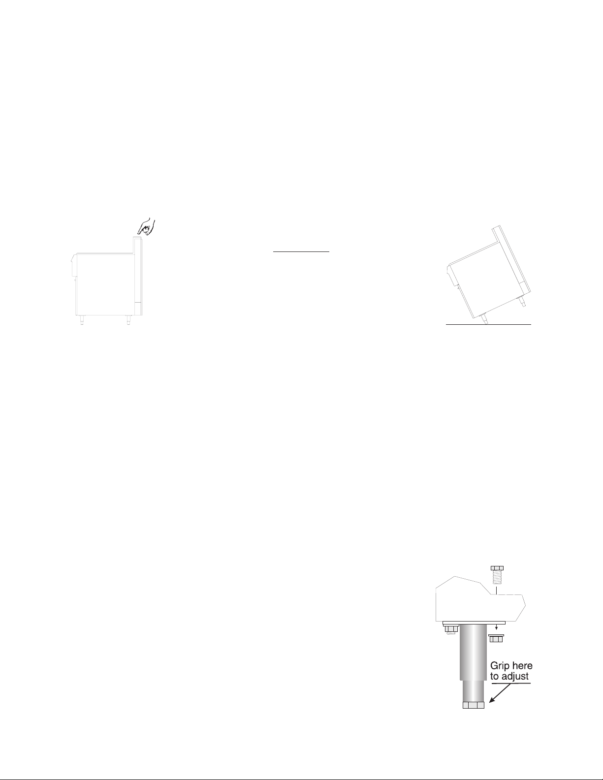
a. Lay the fryer on its back being careful not to damage the flue by
pulling on it. Protect the outside of the fryer with cardboard or a
drop cloth when laying it down.
b. Attach each leg with the hex head cap screws supplied with the
fryer. Each leg requires four 1/4-20 x 5/8" cap screws.
c. Mount the screws from the inside of the fryer with the nut on the
outside of the cooker. The nuts have lock washers attached to
them, therefore it is not necessary to use lock washers.
1-2
Page 12

d. When all four legs are mounted, stand the unit up being careful not to put too much weight
on any one leg. Adjust the height and level the fryer by adjusting the leveling devices on
the leg with the water pump pliers.
1.3.2 Heat Deflector Installation
If the fryer requires a heat deflector, you will find a removable label at the rear top edge of the unit.
This label has instructions for positioning and installation of the heat deflector. Refer to the label and
the instructions below to install the deflector.
a. Remove the two self-drilling screws from the top, back area of the cooker.
b. Position the heat deflector so that the angled portion of the deflector is facing toward the
front of the fryer. Secure the heat deflector to the back of the unit using the sheet metal
screws previously removed.
WARNING
DO NOT obstruct the flow of combustion/ventilation or air openings around
the fryer. Adequate clearance around the fryer is necessary for servicing and
proper burner operation. Ensure that you meet the minimum clearances
specified in the installation instructions.
c. When properly installed the angled section of the heat deflector will extend over the flue
opening to redirect the heat. It SHOULD NOT cover the flue opening. Nothing should
block the flue opening as this will cause the fryer to overheat and produce dangerous
gases.
1.3.3 Splashback Installation
a. Lift the splashback assembly and place over the opening at the back of the tank. Make
sure the front of the splashback faces forward.
b. Using the four supplied countersink screws, attach the splashback to the cabinet sides.
1.3.4 Flue Installation
Insert the flue through the hole in the top of the splashback. Make sure it rests on the flue opening
at the back of the tank.
1.3.5 Drainboard Installation
While the drainboard is being held in place, slide the pivot rod through the holes in the bottom end
of the drainboard. The end of the rod should locate in the hole in the backsplash. The front end is
attached to the top of the tank using a bolt and washer.
1-3
Page 13

1.4 INSTALLATION
WARNING
The fryer must be properly restrained to prevent movement or tipping. This
restraint must prevent the fryer from movements that would splash hot liquids
on personnel. This restraint may be by any means (alcove installation,
adequate ties, or battery installation).
Although it is possible for you to install and set up your new fryer, it is STRONGLY recommended
that you have it done by qualified professionals. The professionals that install your new fryer will
know the local building codes and ensure that your installation is safe.
1.4.1 Installation Clearances
The fryer needs clearance around it for proper operation. Adequate clearances allow for servicing
and proper burner operation. The clearances shown below are for cooker installation in combustible
and non-combustible construction.
Combustible Non-Combustible
Construction Construction
Back 6" 0"
Sides 6" 0"
Floor - Combustible 4-3/4" 4-3/4"
In addition to the clearances required for proper fryer operation, there must be at least 28 inches of
isle space in front of the fryer.
1.4.2 Gas Connection
Your fryer will give you peak performance when the gas supply line is of sufficient size to provide
the correct gas flow. The fryer must be installed to meet the local building codes or National Fuel
Gas Code ANSI Z223.1 Latest Edition. In Canada, install the fryer in accordance with CAN/CGAB149.1 or .2 and local codes. Gas line sizing requirements can be determined by your local gas
company by referring to National Fuel Gas Code, Appendix C, Table C-4 (natural gas) and Table C16 (propane). The gas line needs to be large enough to supply the necessary amount of fuel to all
appliances without losing pressure to any appliance. Other factors that are used to determine the
piping requirements are BTU requirements of the appliances being connected and the length of pipe
between the meter and the appliances.
WARNING
NEVER supply the fryer with a gas that is not indicated on the data plate.
Using the incorrect gas type will cause improper operation. If you need to
convert the fryer to another type of fuel, contact your dealer.
1-4
Page 14
1.4.2.1 Fuel Types - Each fryer is equipped to work with one type of fuel. The type of fuel with
which the appliance is intended to operate is stamped on the data plate attached to the inside of the
door.
WARNING
DO NOT use an open flame to check for gas leaks!
1.4.2.2
before the fryer is used. If the fuel line is going to be tested at a pressure greater than (>)1/2 PSIG
(3.45 kPa), make sure that the fryer is disconnected from the fuel line. If the fuel line is to be tested
at a pressure equal to or less than (
gas valve must be shut. Test all gas line connections for leaks with a solution of soap and water when
pressure is applied.
1.4.2.3 Gas Line Connection - Connect the fryer to the gas supply line with a connector that
complies with the Standard for Connectors for Movable Gas Appliances (ANSI Z21.69 or CAN/
CGA-6.16).
Fuel Supply Line Leak and Pressure Testing - The fuel supply system must be tested
<) 1/2 PSIG (3.45 kPa), the fryer can be connected but the unit's
NOTICE
NEVER use an adaptor to make a smaller gas supply line fit the cooker
connection. This may not allow proper gas flow for optimum burner
operation, resulting in poor cooker performance. NEVER supply the cooker
with any fuel other than the type indicated on the data plate. Using the
incorrect gas type will cause improper operation.
1-5
Page 15

1.4.3 Electrical Connection
The electrical service used by the fryer must comply with local codes. If there are no local codes that
apply, refer to the National Electrical Code (NEC) to install the service. In Canada refer to CSA
Standard C22.1 Canadian Electrical Code Part 1 & 2, and local codes. Wiring diagrams are provided
inside the fryer control box. The power requirements for the fryer are shown below.
North America International
Input Voltage 120 VAC, 60Hz 220 (or 240) VAC, 50Hz
Current per fryer 0.5 Amps 0.5 Amps
WARNING
The fryer is equipped with an oil proof, electrical supply cord with a three
prong safety plug. This is to protect operators from electrical shock hazard
in the event of an equipment malfunction. DO NOT cut or remove the
grounding (third) prong from this plug.
If your fryer uses line current (electric power), a supply cord will be furnished
with a three prong (grounding) plug. This plug provides protection against
shock hazards in the event of equipment malfunction. The plug should be
plugged into a properly grounded three prong receptacle.
The fryer has one power supply which supplies power to the fryer controls. The fryer must be
grounded in accordance with local code; if there is not a local code, comply with NEC ANSI/NFPA
No. 70-1990. It is advised that this power supply be plugged into a wall receptacle that is controlled
by the ventilation control. This will prevent the fryer from being operated without the ventilator on.
1.4.4 Ventilation and Fire Safety Systems
Your new fryer must have proper ventilation to function safely and properly. Exhaust gas
temperatures can reach as high as 1200°F. Therefore, it is very important to install a fire safety
system. Your ventilation system should be designed to allow for easy cleaning. Frequent cleaning
of the ventilation system and the fryer will reduce the chances of fire. Table 1-2 provides a list of
reference documents that provide guidance on ventilation and fire safety systems. This table is not
necessarily complete. Additional information can be obtained from the American Gas Association,
8501 East Pleasant Valley Road, Cleveland, OH 44131.
1-6
Page 16

Table 1-2 Ventilation and Fire Safety References
Topic
Underwriters Laboratory
Document
National Fuel Gas Code
Document
Grease Extractor ANSI/UL 710-1981 ANSI/NFPA 96-1987
Ventilation Hood ANSI/UL 705-1984 ANSI/NFPA 96-1987
Filter Unit ANSI/UL 586-1985
ANSI/NFPA 96-1987
ANSI/UL 900-1987
Types of Fire Extingushers
and Detection Equipment
CO
2
ANSI/UL 154-1983 ANSI/NFPA 12-1989
Dry Chemical ANSI/UL 299-1984 ANSI/NFPA 17-1985
Water ANSI/UL 626-1984 ANSI/NFPA 13-1989
Foam ANSI/NFPA 11-1988
Sprinklers ANSI/UL 199-1982 ANSI/NFPA 13-1989
ANSI/NFPA 13-1989
Smoke Detectors ANSI/UL 268-1981 ANSI/FPA 72B-1986
Fire Detection Thermostats ANSI/UL 521-1987 ANSI/FPA 72B-1986
Excessive ventilation causes drafts, which will interfere with the proper operation of the pilot and the
burner. Leave at least 18 inches of open space between the fryer's flue vent opening and the intake
of the exhaust hood.
CAUTION
Ensure that your ventilation system does not cause a back draft (down draft)
at the fryer's flue opening. Back drafts will not allow the fryer to exhaust
properly and will cause overheating which may cause permanent damage.
Damage caused by backdrafts will not be covered under equipment warranty.
NEVER allow anything to obstruct the flow of combustibles or ventilation
exiting from the fryer flue. DO NOT put anything on top of the flue area.
NOTICE
NEVER connect the ventilation blower directly to the flue openings. The
direct flow of air will cause poor temperature recovery, poor ignition,
inefficient operation of the fryer, and could extinguish the pilot.
1-7
Page 17

1.5 INITIAL ADJUSTMENTS
After your fryer has been installed as described in section 1.4, it needs to be adjusted to ensure that
it will perform as designed. These adjustments must be performed by a qualified person. To perform
these adjustment the following tools will be needed:
• Manometer (low pressure gauge) • Digital Thermometer (Temperature probe)
• DC Millivolt Meter
1.5.1 Visual Checks
Before you begin filling and adjusting the fryer, perform the following
visual checks:
a. After the fryer is in its permanent location check the level-
ness. Any additional leveling that is necessary can be
performed as described in section 1.3.
b. Check the temperature bulb (high-limit), located in the fryer
tank to ensure that the mounting screws are tight. The figure
shows the probe location. Look down inside the fryer tanks
to see the probes.
Ensure that these parts
are not loose.
1.5.2 Burner Ignition Systems
Before going any further, fill the fryer with WATER. Water is used for the
installation adjustments because the temperature will never exceed 212°F
(100°C) thereby allowing plenty of adjustment time. Never let the water level
go below the MIN LEVEL mark on the rear of the tank.
There is an open flame inside the fryer. The unit may get hot enough to set
near by materials on fire. Keep the area around the fryer free from combustibles.
CAUTION
WARNING
1-8
Page 18

1.5.2.1 Lighting Instructions for Manual Pilot Lights - To light the pilot light refer to the
following instructions.
WARNING
Wait 5 minutes before attempting to relight the pilot to allow for any gas in
the fryer to dissipate.
a. Open the gas supply valves to the fryer.
b. Turn the thermostat control knob counterclockwise to the OFF position.
c. Turn the gas valve knob to the PILOT position and push in on the knob.
ON
OFF
P
I
L
O
T
Hold the knob in for approximately one minute to purge the air out of
the line. Hold a flame to the pilot light until the pilot ignites. This may
take a little while the first time you light the fryer because of air in the
lines. Once lit, hold the knob in for approximately 60 seconds and then
release.
d. If the pilot goes out wait 5 minutes and repeat step c. If after three tries the pilot will not
remain lit, refer to the operator troubleshooting section of this manual.
T
e. Turn the gas valve knob counterclockwise to the ON position.
O
L
I
P
OFF
ON
f. Set the thermostat control knob to the desired temperature setting.
g. The main burner will light and be controlled by the thermostat.
1.5.2.1.1 Pilot Flame Adjustment - The pilot flame should be adjusted to produce the proper
millivolt output from the pilot sensing device. Millivolt output for the thermopile should be between
300 and 500 millivolts. This procedure is only necessary on the manual pilot ignition system. Figure
1-1 shows the pilot assembly with examples of the incorrect and correct pilot size. Example A
illustrates a pilot flame size that is too small to produce sufficient millivolt output. Example B is the
correct size for proper millivolt output.
1-9
Page 19

AB
Figure 1-1 Pilot Assembly, Flame Adjustment
a. This test requires a DC millivolt meter set to a scale of 0-1000mv. Using test leads with
sharp probes will help in taking the required reading.
b. Locate the thermopile wires coming from the thermostat/limit box going to the gas valve.
The wire insulation size decreases near the gas valve connections.
c. Using the positive (+) test probe, connect the probe to High Limit wire terminal. On UFM
systems pierce High Limit wire insulation at the gas valve safety magnet connection.
d. Connect the negative (-) test probe to pilot tubing.
e. Remove the pilot flame adjustment cover.
f. Turning the flame adjusting screw clockwise lowers the flame and the millivolt output.
Turning the screw counterclockwise increases flame size and millivolt output.
g. Rotate the screw in the direction to achieve a reading of 400 ±50 mv.
NOTICE
Allow 3 to 5 minutes between flame adjustments to allow the reading to settle.
h. Replace the pilot flame adjusting screw cover.
1.5.2.2 Electronic Ignition Pilot Systems - There is nothing to manually light on the electronic
ignition systems. Pilot ignition is controlled by the electronic pilot system.
a. Open the gas supply valves to the fryer.
b. Turn the thermostat control knob counterclockwise to the OFF position.
1-10
Page 20

c. Turn the gas valve knob to the ON position.
d. Turn the fryer ON/OFF/TEST switch to the ON position. If the fryer is equipped with
the optional melt cycle, place the switch in the MELT ON position.
e. Turn the thermostat to the desired temperature setting.
f. The main burner will light and be controlled by the thermostat.
g. The POWER ON light will come on and remain on as long as the power switch is in the
ON position. The HEATING light will be lit when the main burners are on.
1.5.2.2.1 Electronic Ignition Pilot Flame Adjustment - Figure 1-3 illustrates the pilot adjusting
screw location
a. This test requires that a DC milliammeter be connected between the flame sensor terminal
and the flame sensor lead. Observe correct polarity, if the meter needle goes below 0
milliamps reverse the leads. The current reading must be 0.15 milliamps or greater.
b. Adjust the current reading to the required level by adjusting the pilot flame. Remove the
pilot flame adjustment cover to expose the adjusting screw.
c. Turning the flame adjusting screw clockwise lowers the flame and current. Turning the
screw counterclockwise increases flame size and current.
d. Rotate the screw in the direction to achieve a reading of 0.15 mA or greater.
NOTICE
Allow 3 to 5 minutes between flame adjustments to allow the reading to settle.
e. Once the pilot flame is set, replace the pilot flame adjusting screw cover and remove the
ammeter.
1-11
Page 21

1.5.3 Main Burner System
For the burners to work the gas supply valve must be open and the main power switch must be on.
The main burner receives gas from the main gas supply through the thermostatically controlled valve.
When the thermostat is turned up the gas control valve opens. If you have a pilot light system, the
pilot will ignite the burners. The electronic ignition system will create a spark to ignite the gas. After
the burner system is operating, perform the burner adjustments in the following procedure. Figure
1-2 illustrates the different conditions possible for the main burner.
The tubes and baffles are
badly carbonized. Check
vent and adjust if necessary.
Check for heat tube or flue
blockage.
INSUFFICIENT FLOW EXCESSIVE FLOW
Have gas company check
incoming gas pressure.
Adjust manifold pressure as
described in 1.5.3.2.
The flame seems to "lift off"
the face of the burner.
To correct adjust main
burner as described in
1.5.3.2.
A soft, steady blue flame
should enter the heat tube
without touching the front
outside rim of the tube.
INSUFFICIENT GAS PRESSURE NORMAL FLOW
Figure 1-2 Main Burner Conditions
1-12
Page 22

1.5.3.1 Gas Line Requirements - A properly installed gas supply system will deliver 7.0 ±2.0"
w.c. natural gas (12.0 ±2.0" w.c. LP) to all appliances connected to the line, operating at full demand.
1.5.3.2
Burner Adjustment - The burners must be adjusted to deliver optimum flame. Adjust the
burner flame using the following procedure.
a. Ensure that the main gas valve is shut off, remove the manifold pressure tap plug and
connect an accurate pressure gauge (range of 0-16" w.c. in 0.1" increments) or
manometer.
IN
Figure 1-3 Typical Gas Valve Showing Location of Pressure Regulator and Pilot Adjusters
b. Turn on all appliances connected to the gas supply line and light their main burners. The
pressure reading of the installed pressure gauge should not drop from the required
installation pressure. Any loss of pressure indicates inadequate supply line installation
which will cause poor performance of all appliances during peak usage.
c. The installed pressure gauge reading should be the same, ±0.1", as that marked on the data
plate inside the door. If the pressure is correct go to step e, if not, adjust the pressure.
d. To adjust the pressure, remove the regulator adjustment screw cover (see Figure 1-3). Use
a flat tip screwdriver to adjust the screw until the proper pressure is reached. Turning the
screw clockwise will increase the pressure, counterclockwise will decrease the pressure.
e. When the pressure is correct, install the regulator adjustment screw cover.
f. To remove the pressure gauge, turn off fryer and shut the main gas valve. Remove the
gauge and install the pressure tap plug.
1-13
Page 23

Figure 1-4 Air Collar
g. Now that the pressure is set for proper operation, set the main burner flame. Unlock the
air collars by loosening the set screw for the collars. Open the main gas valve, (light the
pilot if fryer has manual pilot), and turn thermostat to light the main burners.
h. Adjust the shape and size by raising or lowering the air collars to achieve a soft blue flame
with well defined inner cones.
i. When the flames have been properly adjusted, lock the collars in place with the set screw.
1.5.4 INITIAL CLEANING
When the fryer is shipped, many of its parts are covered with a thin coat of oil for protection. Before
the fryer is ready for cooking it must be cleaned. This will remove the oil coating and any foreign
matter that may have accumulated during storage and shipment. Perform the cleaning as described
below.
a. Fill the fryer with water. Turn the fryer on and set the thermostat to 200°F.
b. Allow the fryer to heat for 15 minutes. Add Pitco cleaner, stirring with the fryer cleaning
brush to ensure cleaner has dissolved thoroughly.
NOTICE
Do not leave the fryer unattended during cleaning. Never let the water level
go below the "Min Level" mark on the back of the tank.
1-14
Page 24

c. Using the fryer cleaning brush, scrub the inside of the fryer to remove protective coating.
d. When cleaning is complete, turn off the fryer by turning the gas valve knob to the PILOT
position. Drain the water into a container suitable for hot water and dispose of it.
e. When the tank has cooled, rinse it thoroughly with cool water. Continue to rinse the tank
until the cleaner has been rinsed, thoroughly from the tank.
f. Using a clean dry cloth, wipe out all of the water. Be very thorough removing the water,
because any residual water will cause hot oil to splatter out of the fryer.
CAUTION
Mild steel tanks must be wiped down/coated with oil to keep the tank from
rusting.
g. Now that the tank is clean, you are ready to fill and operate the fryer. Refer to 2.1 for
instructions on adding shortening to the fryer.
1.5.5 Thermostat Calibration Check (Standard)
NOTICE
Thermostat calibration requires that the temperature of the fryer be raised
above boiling. Therefore, you will need to drain the water from the fryer and
fill it with oil. Before removing the water, perform the initial cleaning of the
fryer. Cleaning the fryer now will prevent you from having to drain the oil and
refill with water later.
Filling the fryer with oil is described in 2.1. To perform the calibration check detailed below you will
need a digital thermometer.
a. Place the tip of the thermometer in the shortening approximately 1" above the temperature
sensors.
b. Set the thermostat at 325°F and wait for the temperature reading on the thermometer to
rise. As the temperature rises toward 325°F watch the thermometer closely.
c. If the shortening temperature reaches 350°F and the burners DO NOT turn off, turn the
thermostat down. Keep lowering the thermostat setting until the burners go out.
CAUTION
If the burners do not turn off at the lowest thermostat setting, the thermostat
could be defective. Contact your ASAP representative.
1-15
Page 25

d. Let the fryer cycle 4 to 6 times before checking the temperature. Compare the
thermometer temperature against the thermostat setting. If the values are more than 5°F
apart, calibrate the thermostat using the appropriate calibration procedure in this manual.
1.5.6 Thermostat Calibration
There are two types of thermostats that can be calibrated, a Robertshaw electric and a gas operated
manual mechanical. Both thermostats are calibrated by following the procedures below.
a. Place the tip of the thermometer in the shortening approximately 1" above the temperature
sensors.
b. Set the Thermostat to 325°F and wait for the temperature reading on the thermometer to
rise.
c. Let the fryer cycle 4 to 6 times to ensure that the temperature has stabilized. Compare the
thermometer temperature against the thermostat setting.
d. Remove the thermometer dial by pulling the knob straight out. DO NOT rotate the dial.
e. Hold the outside of the shaft so it does not move. Use the tip of a small, flat tip screw driver
to scrape away the sealing compound from the adjustment screw.
f. Turn the adjustment screw clockwise to lower the temperature setting and counterclock-
wise to raise the temperature. One quarter turn changes the temperature approximately
25°F.
g. Turn the adjustment until the burners turn on at 325°F. Replace the knob and allow the
fryer to cycle 4 to 6 times. Check the temperature of the thermometer against the
thermostat dial, if it is greater than 5°F difference repeat the calibration procedure.
h. When the calibration is correct, remove the thermometer and replace the tube screen.
1.5.7 Thermostat Calibration (Solid State)
The solid state thermostat knob has the temperature settings imprinted in the panel behind the dia.
a. Place the tip of the thermometer in the shortening approximately 1" above the temperature
sensors.
b. Set the Thermostat to 325°F and wait for the temperature reading on the thermometer to
rise.
1-16
Page 26

c. Let the fryer cycle 4 to 6 times to ensure that the temperature has stabilized. Compare the
thermometer temperature against the thermostat setting. If the values are more than 5°F
apart, go to step d. If the values are within 5°F, the thermostat is operating correctly.
d. Loosen the set screw that holds the thermostat knob to its shaft.
e. Rotate the thermostat dial, without moving the shaft, to the temperature indicated on the
thermometer. Tighten the set screw on the thermostat dial to lock the dial in place.
f. Adjust the thermostat to a new setting and allow the fryer to cycle 4 to 6 times at the new
setting. Check the thermometer temperature against the dial setting. If the temperature
is ±5°F of the thermostat dial setting, remove the thermometer and replace the tube screen.
If the temperature is greater than ±5°F away from the dial setting, perform the above
procedure again.
1-17
Page 27

1-18
Page 28

Chapter 2: Operating Instructions
This chapter describes how to operate your fryer to obtain the best performance. Included in this
chapter are filling, operating, and cleaning instructions for gas fryers.
2.1 FILLING THE FRYER
Both liquid and solid shortening can be used in the fryer, but liquid is preferred. If solid shortening
is used, it is recommended that you melt the shortening before adding it to the fryer. You can melt
solid shortening in the fryer, but you must carefully not to scorch the shortening.
2.1.1 Filling the Fryer With Liquid Shortening
a. Make sure the drain valve is completely closed.
b. Fill the fryer with oil to the "Oil Level" line marked on
the back of the tank.
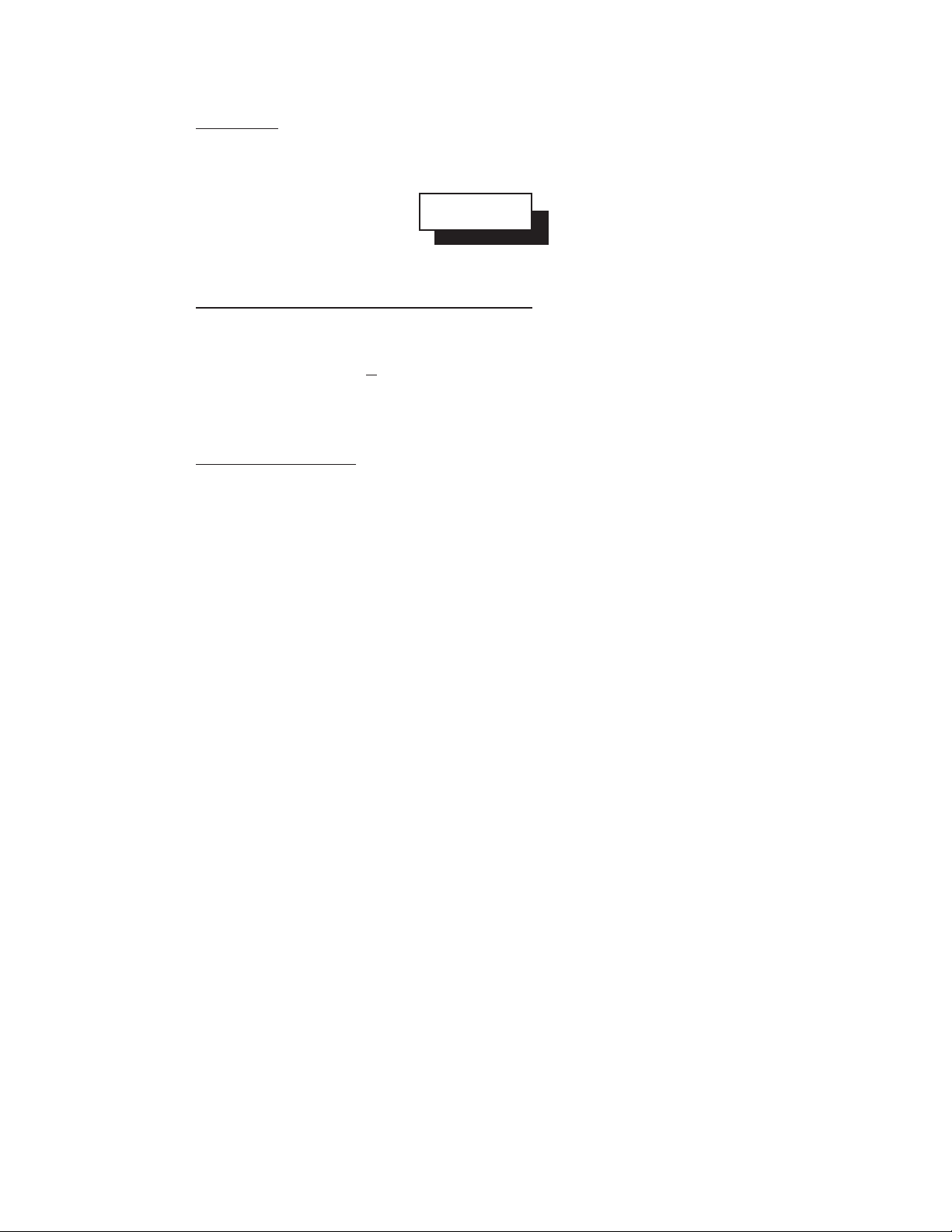
2.1.2 Filling the Fryer With Solid Shortening
WARNING
Solid
Shortening
Solid
Shortening
Never melt blocks of solid shortening on top of the burner
tubes. This will cause a fire, and will void your warranty.
Temp . P rob e
Tube s
a. Make sure the drain valve is completely closed.
b. Remove the screen covering the tubes.
c. Cut the shortening into cubes no larger than 1". ALWAYS
pack the shortening below, between, and on top of the
burner tubes. DO NOT leave any large air gaps. Use care
when packing the solid shortening in the tank. DO NOT
bend or break the temperature sensor probes. If these are
damaged the fryer will not function properly.
o
l
i
O
r
S
h
o
r
t
e
n
Burner Tubes
g
n
i
Temp . Prob e
Tube s
Shortening
Blocks
d. Once the fryer is packed with shortening, the shortening
must be melted. Melt the shortening by cycling the main
burners on for 4 seconds and leaving the burners off for 30
seconds.
2-1
Temp . P rob e
Excessive Air Gaps
Tube s
Page 29

2.2 OPERATING INSTRUCTIONS
To ensure the food always comes out the very best, follow the preparation instructions for the food
you are cooking. Using the best shortening makes the best fried foods. The best shortening will last
longer than lower grade shortening and save you money. When not in use the shortening should be
cooled and covered to prevent contamination.
CAUTION
This fryer has been installed using restraining devices to prevent accidental
tipping or movement. Do not attempt to move the fryer when it has hot liquid
in it. Splashing hot liquids can cause severe burns.
WARNING
Water and shortening DO NOT mix. Keep liquids away from hot shortening.
Dropping liquid frozen food into the hot shortening will cause violent boiling.
2.2.1 Fryer Start-Up
DO NOT START FRYER WITHOUT FILLING WITH OIL!
a. Light the pilot light as described in section 1.5.2.
b. Turn the temperature control knob (thermostat) to the desired temperature setting. This
knob is located behind the front doors or on the front control panel.
c. The main burners will light and raise the temperature of the fryer.
2.2.2 Fryer Shut-Down
There are two shutdown modes of fryer operation, STANDBY and COMPLETE. The standby mode
removes the ability for the fryer's main burners to cycle. Complete shutdown turns off the gas supply
to the fryer. Shut down the fryer by:
ON
OFF
P
I
L
O
T
STANDBY Turn the thermostat to OFF. Turn the gas valve clockwise to the
PILOT position. The cooker is now in Standby and can remain this
way for only brief periods of time. NEVER leave the cooker in
standby overnight.
COMPLETE To completely shut down the cooker, depress and turn the gas valve
counterclockwise to the OFF. The fryer is now completely shut
down and can be cleaned and filtered.
ON
T
OFF
P
I
L
O
2-2
Page 30

2.2.3 Power Failure
NOTICE
No attempts should be made to operate the fryer during power outages.
If your fryer is supplied with AC power and, it is removed from the unit for any reason during
operation, the fryer will shut down. Wait five minutes after power is restored before restarting the
fryer. This will give any gas fumes in the burner time to dissipate. To restart the fryer, follow the
Fryer Start-Up procedures as you normally would.
2.3 DAILY CLEANING
Your fryer should be cleaned every day to maintain peak performance and appearance. Perform the
procedures below every day.
a. Wipe up any shortening that spills onto the exterior of the fryer. This should be done with
a clean soft cloth while the oil is still warm.
b. Use warm water with a mild detergent to clean surfaces. Be careful not to get water in
the shortening and to remove any detergent from the fry tank.
c. Use a non-abrasive scouring powder or pad to clean stains if necessary.
d. Perform the weekly boil out cleaning of your fryer described in section 3.1.
2-3
Page 31

2-4
Page 32

Chapter 3: Owner Maintenance and Adjustments
This chapter provides you with the information and procedures necessary to perform basic fryer
maintenance and adjustments. If after performing maintenance on your fryer it does not perform
properly, contact your authorized service center.
WARNING
The power supply must be disconnected before servicing or cleaning the
appliance.
WARNING
At operating temperature, the shortening in the fryer may be hotter than 375°F
(190°C). This hot, melted shortening can cause severe burns. Do not let the
hot shortening touch your skin or clothing. Always wear insulated oil-proof
gloves when working on hot fryers
3.1 WEEKLY FRYER CLEANING (BOIL OUT)
The fryer should be thoroughly cleaned once a week. This cleaning should include a complete
draining of the fryer and a boil out.
a. You will need a container large enough to hold 1 1/2 times the oil in one tank. This
container must also be able to withstand operating temperature oil.
CAUTION
Completely shut down the fryer when the oil is being replaced by water. This
will prevent the main burners from coming on during the oil draining and
water filling procedure.
b. Drain the oil from the fryer and discard or save for reuse. Remove the tube cover screens.
Close the drain valve and fill the tank with warm water and non-caustic detergent. For
best results use Pitco Fryer Cleaner part number P6071397 (sample packet included with
your new fryer).
c. Restart your fryer as described in 2.3 and set the thermostat to 200°F and bring the water
to a slow boil. DO NOT allow water to boil because excessive foaming will occur.
d. Allow the fryer to soak for 20 minutes to soften shortening deposits. Use fryer brush to
remove any residue from tank, tubes, and side walls. Perform the daily cleaning
procedure described in section 2.7.
3-1
Page 33

e. Wipe the tank dry with soft clean cloth. Close the drain valve and remove the large
container.
f. Replace the tube screens and refer to section 2.1 to refill the fryer.
3-2
Page 34

3.2 FRYER TROUBLESHOOTING
Refer to this section to correct common problems that may be encountered in equipment operation.
Fryer does not
work.
Will the
pilot light?
YES
Does pilot
remain lit after
Unitrol Knob is
released?
YES
Does pilot
go out when the
temperature
increases?
NO
NO
YES
Is the gas
supply
valve open?
YES
Purge air from gas
line (1.5.2)
Is all the air
purged from the
gas line?
YES
Purge air from gas line by
placing the Unitrol Valve
knob in PILOT and holding
in for approx. 1 minute.
Contact a Qualified
Technician.
NO
NO
Open the gas valve
and light pilot (1.5.2)
Is High Limit
Switch open?
Contact a
Qualified
Technician.
YES
NO
Will Limit
switch reset?
YES
Reset &
Light Pilot
NO
Contact a
Qualified
Technician.
NO
Does the Main
burner light?
YES
If the main burner is lighting but not
performing properly refer to Chapter
1 to verify proper installation or
contact a qualified technician.
NO
Is the Unitrol gas
valve knob in the ON
position?
NO
Turn Unitrol gas
knob to ON.
3-3
YES
knob in the OFF
Turn Thermostat to a
temperature setting.
Is the
Thermostat
position?
YES
NO
Contact a Qualified
Technician.
Page 35

3-4
 Loading...