

Page 1
Page 2
NOTICES
TO THE PURCHASER
There are three different types of notices that you should be familiar with, a NOTICE, CAUTION, and
WARNING. A NOTICE is a special note used to call attention to a particularly important point. CAUTION
is used to point out a procedure or operation which may cause equipment damage. The WARNING notice is
the most important of the three because it warns of an operation that may cause personal injury. Please
familiarize yourself with your new cooker before operating it and heed the notices throughout this manual.
The WARNINGS are listed below and on the following page for your review prior to operating the unit.
FOR YOUR SAFETY
DO NOT store or use gasoline or other flammable
vapors or liquids in the vicinity of this or any other
appliance.
WARNING: Improper installation, adjustment, alteration,
service or maintenance can cause property dam age, injury or
death. Read the installation, operating and maintenance
thoroughly before installing or servicing this equipment.
POST IN A PROMINENT LOCATION INSTRUCTIONS TO BE
FOLLOWED IN THE EVENT THAT AN OPERATOR SMELLS
GAS. OBTAIN THIS INFORMATION FROM YOUR LOCAL GAS
SUPPLIER.
THIS MANUAL MUST BE RETAINED FOR FUTURE REFERENCE
Page 3
SAFETY SAFETY SAFETY SAFETY SAFETY
There is an open flame inside the fryer. The unit may get hot enough to set near by materials on
fire. Keep the area around the fryer free from combustibles.
DO NOT supply the fryer with a gas that is not indicated on the data plate. If you need to
convert the fryer to another type of fuel, contact your dealer.
DO NOT use an open flame to check for gas leaks!
Wait 5 minutes before attempting to relight the pilot to allow for any gas in the fryer to
dissipate.
Never melt blocks of shortening on top of the burner tubes. This will cause a fire, and void your
warranty.
Water and shortening DO NOT mix. Keep liquids away from hot shortening. Dropping liquid
frozen food into the hot shortening will cause violent boiling.
At operating temperature the shortening temperature will be greater than 300'F. Extreme care
should be exercise when working with hot shortening to avoid personnel injury.
Ensure that the fryer can get enough air to keep the flame burning correctly. If the flame is
starved for air it can give off a dangerous carbon monoxide gas. Carbon Monoxide is a clear
odorless gas that can cause suffocation.
In the event of a oil fire in the fryer, use ONLY a dry chemical extinguisher. The exti nguisher
should be a B/C or A/B/C type extinguisher that contains sodium bicarbonate or potassium
bicarbonate.
SAFETY SAFETY SAFETY SAFETY SAFETY
Page 4

Table of Contents
1.3.2
Gas Connection
1-4
1.3.2.2
Gas Line Connection
1-4
1.3.3
Electrical Connection
1-5
1.4
INITIAL ADJUSTMENTS
1-7
1.4.3
Pilot Flame Adjustment
1-10
2.2
FRYER OPERATING INSTRUCTIONS
2-2
Section Title Page
Safety Notice
Table of Contents
List of Tables and Figures iv
CHAPTER 1: GENERAL INFORMATION AND INSTALLATION 1-1
1.1 FRYER SPECIFICATIONS 1-1
1.2 CHECKING YOUR NEW FRYER 1-2
1.2.1 Check Your Order 1-2
1.3 INSTALLATION 1-3
1.3.1 Installation Clearances 1-3
1.3.1.1 Leveling 1-3
1.3.2.1 Fuel Types 1-4
1.3.2.3 Quick Disconnect Gas Connection 1-5
1.3.2.4 Fuel Supply Line Leak and Pressure Testing 1-5
1.3.3.1 Electrical System with UFM Filter System 1-6
1.3.4 Ventilation and Fire Safety Systems 1-6
1.4.1 Visual Checks 1-7
1.4.2 Burner Ignition Systems 1-8
1.4.2.1 Lighting Instructions/or Manual Pilot Lights 1-8
i-ii
1.4.4 Main Burner System 1-12
1.4.4.1 Gas Line Requirements 1-13
1.4.4.2 Burner Adjustment 1-13
1.5 INITIAL CLEANING 1-14
CHAPTER 2: OPERATING INSTRUCTIONS 2-1
2.1 FILLING THE FRYER 2-1
2.1.1 Filling the Fryer With Liquid Shortening 2-1
2.1.2 Filling the Fryer With Solid Shortening 2-1
2.2.1 Fryer Start-up 2-2
2.2.2 Displaying Temperatures 2-3
2.2.2.1 Shortening Actual Temperature 2-3
2.2.2.2 Cooking Setpoint 2-4
2.2.3 Display Product Times 2-4
Page 5

Table of Contents (Continued)
Section Title Page
2.2.3.1 Viewing Product Times 2-4
2.2.4 Cooking Product 2-4
2.2.5 Shutdown 2-5
2.2.4 Power Failure 2-5
2.3 PROGRAMMING THE INTELLIFRY COMPUTER 2-6
2.3.1 Basic Programming 2-6
2.3.1.1 Programming Shortening Temperature 2-6
2.3.1.2 Programming Product Times 2-7
2.3.2 Low Level Programming 2-8
2.3.2.1 Temperature display 2-8
2.3.2.2 Password 2-8
2.3.2.3 Beeper Volume 2-9
2.3.2.4 Languages 2-10
2.3.2.5 MeAC^cfc 2-10
2.3.2.6 Recovery Test 2-11
2.3.2.7 Computer Control Mode 2-11
2.4 SHORTENING FILTER PROCEDURES 2-13
2.4.1 General Filter Hints 2-15
2.4.2 Filter Procedures 2-16
2.4.3
Draining a Tank
2-17
CHAPTER 3: OWNER MAINTENANCE AND ADJUSTMENTS 3-1
3.1 FILTER MEDIA REPLACEMENT 3-1
3.2 FRYER CLEANING 3-3
3.2.1 Daily 3-3
3.2.2 Weekly (Boilout) 3-3
3.3 FLUE AND BAFFLE INSPECTION 3-4
3.4 SERVICE 3-4
3.4.1 Replacement Procedures 3-4
3.4.1.1 Main Burner Removal and Replacement 3-5
3.4.1.2 Changing the Main Burner Orifice 3-5
3.4.1.3 Replacing the Heat Baffles 3-5
3.4.1.4 Pilot Burner Removal and Replacement 3-5
3.4.1.5 Pilot Orifice Replacement 3-5
3.4.1.6 Thermopile Replacement 3-6
3.4.1.7 Limit Control Replacement 3-6
3.5 TROUBLESHOOTING 3-8
3.5.1 Fryer Troubleshooting 3-8
3.5.2
Pilot Troubleshooting
ii
3-9
Page 6

Table of Contents (Continued)
Section Title Page
3.5.3 Filter Troubleshooting 3-10
CHAPTER 4: PARTS 4-1
ALPHABETICAL PART LIST 4-5
NUMERICAL PART LIST 4-7
CHAPTER 5: SCHEMATICS 5-1
iii
Page 7

List of Tables and Figures
Table Title Page
1-1 Fryer Characteristics............................................................................................….... 1-1
1-2 Ventilation and Fire Safety References................................................................…... 1-7
4-1 Wendy's Model W14-3UFM Exploded View (Index)............................…...........…. 4-2
Figure Title Page
1-1 Inside View of Fryer.........................................................................................…..…1-9
1-2 Pilot Assembly, Flame Adjustment..............................................................….….... 1-10
1-3 Gas Valve Showing Location of Pressure Regulator and Pilot Adjusters ......…...... 1-10
1-4 Main Burner Conditions ....................................................................................…... 1-12
1-5 Air Collar ..........................................................................................................….... 1-13
2-1 Intellifry Computer..............................................................................................….. 2-2
2-2 Fryer Illustrating Filter Components ..................................................................…...2-13
4-1 Wendy's Model W14-3UFM Exploded View...............................................…….... 4-3/4-4
iv
Page 8
CHAPTER 1: GENERAL INFORMATION AND INSTALLATION
Congratulations on the purchase of your new Pitco Model W1 4S-3 WF gas fryer. This unit has been
specially designed to suit the needs of your establishment and will give you many years of reliable service if
you follow the simple operation and maintenance procedures in this manual. Contained in this manual are
the general installation, operation, and maintenance procedures for the Model Wl 4-3 WF gas fryer.
1.1 FRYER SPECIFICATIONS
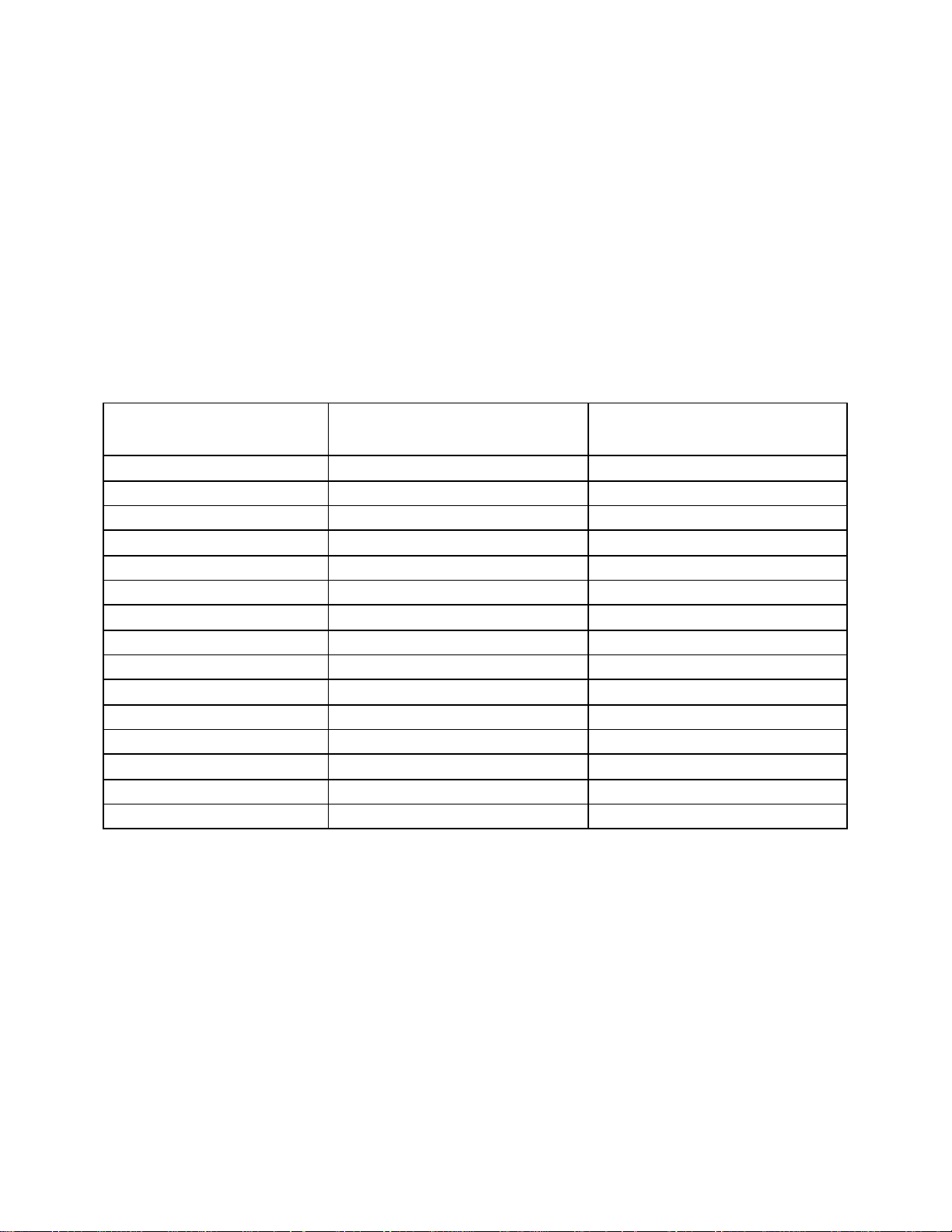
This unit has been designed to fit the need of the Wendy's chain of stores. The table below lists the
characteristics and specifications associated with this unit:
Table 1-1 Fryer Characteristics
Description Specification (US) Specification (Metric)
Height, Overall 48" 121.9cm
Height, Working 35" 88.9 cm
Width (Unit) 48-3/8 122.9cm
Depth (Unit) 34" 86.4 cm
Number of Tanks/Unit 3 3
Frying Area/Tank 14"x 14" 35.6 x 35.6 cm
Frying Depth 4" 10.2 cm
Aisle space (minimum) 21" 53.3 cm
Oil Capacity/Tank 40 - 42 Lbs 18.1 -19.1 Kg
Input/Tank (BTU/Hr) 122,000 (per tank) 30,744KCal
Gas Type LP or Natural LP or Natural
Input Voltage 120 VAC Single Phase 120 VAC Single Phase
Current Requirements/Unit 9 Amps 6 Amps
Filter Media Filter Paper Filter Paper
Pump Rate 5.0 GPM 18.9LPM
1-1
Page 9

1.2 CHECKING YOUR NEW FRYER
Your new fryer and it's filter components have been carefully packed into one crate. Every effort has been
made to ensure that your fryer will be delivered to you in perfect condition. As you unpack your new fryer,
inspect each of the pieces for damage. If something is damaged, DO NOT sign the bill of lading. Contact the
shipper immediately, the shipper is only responsible for 15 days after delivery. Check the packing list
enclosed with your fryer to ensure that you have receiv ed all of the parts to the fryer. If you are missing any
parts, contact the dealer from whom the fryer was purchased. As you unpack the fryer and it's accessories be
careful to keep the weight of the fryer evenly
distributed.
Flue Vents
CAUTION
To prevent equipment damage, don't tilt the fryer onto any two of
it's casters or pull the unit by the flue vents.
You will find the model and serial numbers on the plate inside the doors. Make note of these numbers
for future reference
1.2.1 Check Your Order
The crate containing the fryer unit will also contain the following:
(2) Fry baskets per fryer
(1) Fry Basket Hanger per fryer
(2) Pitco Cleaner Sample
(1) Drain Clean Out Rod
The filter tools and components are very important and MUST be retained for future use. A complete
description of each component is contained in the Oil Filter Procedure in Chapter 2.
(1) Precoat Filter Aid
(1) Filter Screen
(1) Cleaning Brush (Fryer)
(1) Fryer Crumb Scoop
(1) Filter Crumb Scoop
1-2
Page 10
1.3 INSTALLATION
Although it is possible for you to install and set up your new fryer, it is STRONGLY recommended that you
have it done by qualified professionals. The professionals that install your new fryer will know the local
building codes and ensure that your installation is safe.
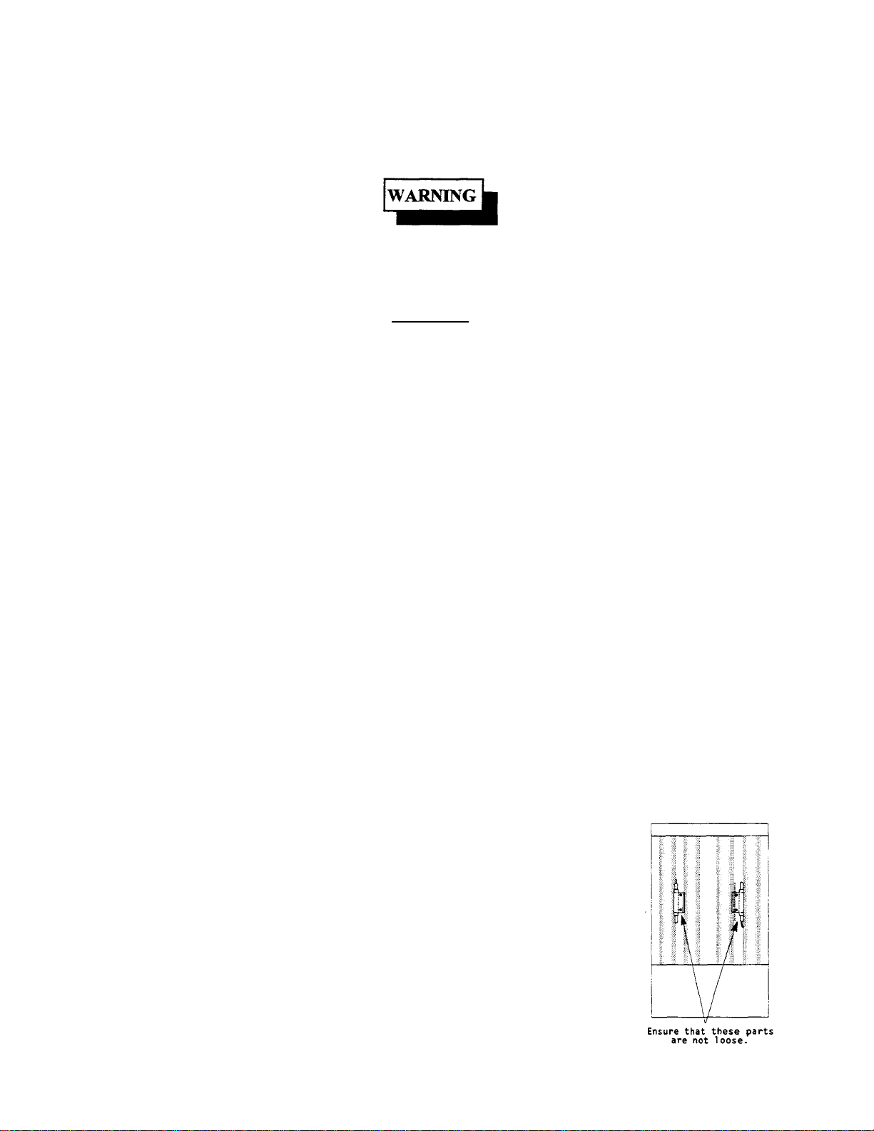
The fryer must be properly restrained to prevent movement or tipping. This
restraint must prevent the fryer from movements that would splash hot
liquids on personnel. This restraint may be any means (alcove installation,
adequate ties, or battery installation).
DO NOT obstruct the flow of combustion/ventilation or air openings around
the fryer. Adequate clearance around the fryer is necessary for servicing and
proper burner operation. Ensure that you meet the minimum clearances
specified in the installation instructions.
1.3.1 Installation Clearances
The fryer needs clearance around it for proper operation. Adequate clearances allow for servicing and proper
burner operation. The clearances shown below are for cooker installation in combustible and noncombustible construction.
Combustible Non-Combustible
Construction Construction
Back 6" 6"
Sides 6" 6"
Floor – Combustible -- --
In addition to the clearances required for proper fryer operation, there must be at least 21 inches of aisle
space in front of the fryer to remove/install the filter pan/module.
1.3.1.1 Leveling
When you receive your fryer it is completely assembled. The fryer will need to be leveled once it is in place.
Leveling the fryer is done with a large pair of water pump pliers. The casters provide the necessary height to
meet sanitation requirements and assure adequate air supply to the burner.
a. Adjust the height and level the fryer by adjusting the leveling devices on the caster with the water pump
pliers.
1-3
Page 11
b. Move the fryer to the desired location and lock the wheels using the locking devices on the sides of the
WARNING
casters.
c. Once the unit is in place, check and readjust the levelness as necessary.
1.3.2 Gas Connection
Your fryer will give you peak performance whe n the gas supply line is of sufficient size to provide the
correct gas flow. The gas line must be installed to meet the local building codes or National Fuel Gas Code
(NFPA 54-1984) and ANSI Z223. 1-1988 Latest Edition. In Canada, install the fryer in accordance with
CAN/CGA-B 149.1 or .2 and local codes. Gas line sizing requirements can be determined by your local gas
company by referring to National Fuel Gas Code, Appendix C, Table C-4 (natural gas) and Table C-16
(propane). The gas line needs to be large enough to supply the necessary amount of fuel to all appliances
without losing pressure to any appliance. Other factors that are used to determine the piping requirements
are BTU requirements of the appliances being connected and the length of pipe between the meter (main
shut off) and the appliances.
NEVER supply the fryer with a gas that is not indicated on the data plate. Using
the incorrect gas type will cause improper operation. If you need to convert the
fryer to another type of fuel, contact your dealer.
1.3.2.1 Fuel Types
Each fryer is equipped to work with one type of fuel. The type of fuel with which the appliance is intended
to operate is stamped on the data plate attached to the inside of the door.
DO NOT use an open flame to check for gas leaks!
1.3.2.2 Gas Line Connection
Connect the fryer to the gas supply line with a connector that complies with the Standard for Connectors for
Movable Gas Appliances (ANSI Z21.69-1987). If you are installing a fryer with casters using a quick
disco nnect refer to the Quick Disconnect installation instruction, 1.3.2.3. Connect the gas line to the fryer
using a pipe joint sealant that is resistant to liquefied petroleum. If the fryer was disconnected during the fuel
line testing, use a solution of soap and water to leak test the new connection.
NOTICE
NEVER use an adaptor to make a smaller gas supply line fit the cooker
connection. This may not allow proper gas flow for optimum burner operation,
resulting in poor cooker performance.
1-4
Page 12
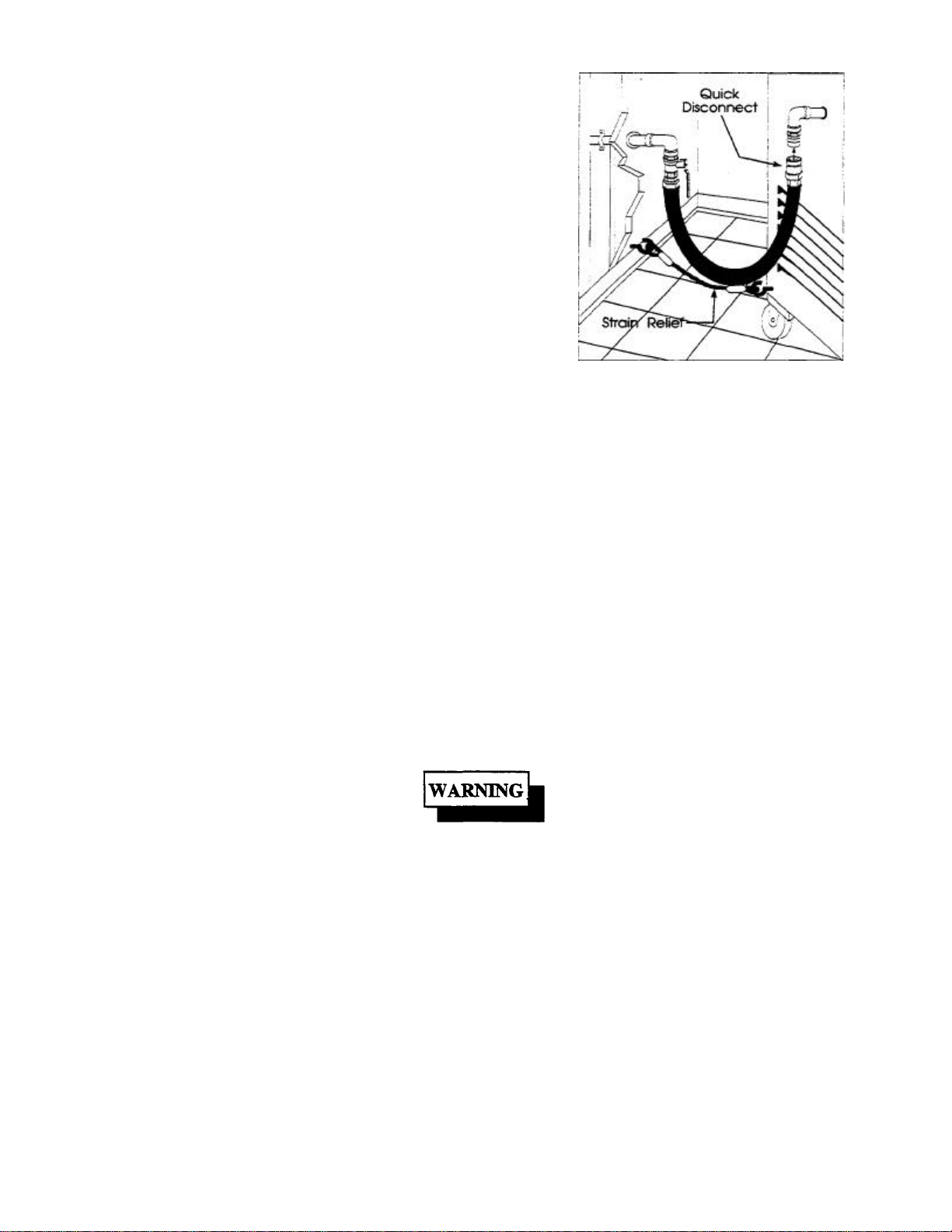
1.3.2.3 Quick Disconnect Gas Connection
International
Gas fryers equipped with casters must be installed with connectors
that comply with the Standard for Connectors for Movable Gas
Appliances, ANSI Z21.69-1987, and Addenda Z21.69A -1989. This
connection should include a quick disconnect device that complies
with the Standard for Quick Disconnect Devices for Use With Gas
Fuel, ANSI Z21.41-1989. When installing a quick disconnect you
must also install a means for limiting the movement of the fryer.
This device will preve nt the gas line or the quick disconnect from
being strained. The restraining device should be attached to the
cooker on the back panel as shown in the illustration. The quick
disconnect, hose, and restraining device can be obtained from your
dealer.
1.3.2.4 Fuel Supply Line Leak and Pressure Testing
The fuel supply system must be tested before the fryer is used. If the fuel line is going to be tested at a
pressure greater than (>)1/2 PSIG (3.45 kPa), make sure that the fryer is disconnected from the fuel line. If
the fuel line is to be tested at a pressure equal to or less than (<) 1/2 PSIG (3.45 kPa), the fryer can be
connected but the unit's gas valve must be shut. Test all gas line connections for leaks with a solution of
soap and water when pressure is applied.
1.3.3 Electrical Connection
The electrical service used by the fryer must comply with local codes. If there are no local codes that apply,
refer to the National Electrical Code (NEC) to install the service. In Canada refer to CSA Standard C22.1
and local codes. Wiring diagrams are provided inside the fryer control box. The power requirements for the
fryer are shown below.
North America
Input Voltage
Current per fryer
UFM Filter System
120VAC,60Hz
0.5 Amps
7.0 Amps
220 (or 240) VAC, 50Hz
0.5 Amps
4.0 Amps
The fryer is equipped with an oil proof, three prong (grounding) plug for your
protection against electrical shock hazard in the event of equipment
malfunction. DO NOT cut or remove the grounding (third) prong from this
plug. This plug must be plugged into a properly grounded three prong
receptacle.
1-5
Page 13
The fryer must be grounded in accordance with local code; if there is not a local code, comply with
NECANSI/NFPANo. 70-1990. It is advised that this power supply be plugged into a wall receptacle that is
controlled by the ventilation control. This will prevent the fryer from being operated without the ventilator
on.
1.3.3.1 Electrical System with UFM Filter System
The fryer has one power supply for the controls and the filter module.
1.3.4 Ventilation and Fire Safety Systems
Your new fryer must have proper ventilation to function safely and properly. Exhaust gas temperatures can
reach as high as 1200°F. Therefore, it is very important to install a fire safety system. Your ventilation
system should be designed to allow for easy cleaning. Frequent cleaning of the ventilation system and the
fryer will reduce the chances of fire. Table 1-2 provides a list of reference documents that provide guidance
on ventilation and fire safety systems. This table is not necessarily complete. Additional information can be
obtained from the American Gas Association, 8501 East Pleasant Valley Road, Cleveland, OH 44131.
Table 1 -2 Ventilation and Fire Safety References
Topic Underwriters Laboratory Document
Grease Extractor ANSI/UL710-1981 ANSI/NFPA 96-1987
Ventilation Hood ANSI/UL 705-1984 ANSI/NFPA 96-1987
Filter Unit
Types of Fire Extinguishers
and Detection Equipment
CO2 ANSI/UL 154-1983 ANSI/NFPA 12-1989
Dry Chemical ANSI/UL 299-1984 ANSI/NFPA 17-1985
Water ANSI/UL 626-1984 ANSI/NFPA 13-1989
Foam
Sprinklers ANSI/UL 199-1982
Smoke Detectors ANSI/UL 268-1981 ANSI/FPA72B-1986
ANSI/UL 586-1985
ANSI/UL 900-1987
National Fuel Gas Code
Document
ANSI/NFPA 96-1987
ANSI/NFPA 11-1988
ANSI/NFPA 13-1989
ANSI/NFPA 13-1989
Fire Detection Thermostats ANSI/UL 521-1987 ANSI/FPA72B-1986
1-6
Page 14
Excessive ventilation causes drafts, which will interfere with the proper operation of the pilot and the burner.
Leave at least 18 inches of open space between the fryer's flue vent opening and the intake of the exhaust
hood.
In the event of an oil fire in the fryer, use ONLY a dry chemical extinguisher. The
extinguisher should be a B/C or A/B/C type extinguisher that contains sodium
bicarbonate or potassium bicarbonate.
Ensure that your ventilation system does not cause a down draft at the fryer's flue
opening. Down drafts will not allow the fryer to exhaust properly and will cause
overheating which may cause permanent damage. Damage caused by down drafts
will not be covered under equipment warranty. NEVER allow anything to obstruct
the flow of combustibles or ventilation exiting from the fryer flue. DO NOT put
anything on top of the flue area.
NEVER connect the blower directly to the flue openings. The direct flow of air will
cause poor temperature recovery, poor ignition, inefficient operation of the fryer,
and could extinguish the pilot.
1.4 INITIAL ADJUSTMENTS
CAUTION
NOTICE
After your fryer has been installed as described in section 1.4, it needs to be adjusted to ensure that it will
perform as designed. These adjustments must be performed by a qualified person. To perform these
adjustment the following tools will be needed:
• Manometer (low pressure gauge)
• DC Millivolt Meter
1.4.1 Visual Checks
Before you begin filling and adjusting the fryer, perform the following visual checks:
a. After the fryer is in its permanent location, lock the casters and check for
levelness. Any additional leveling that is necessary can be performed as
described in section 1.3.
b. Check the temperature bulb s (computer/high-limit), located in the fryer tank to
ensure that the mounting screws are tight. The figure shows the probe typical
location. Look down inside each fryer tank to see the probes.
• Digital Thermometer (Temperature probe)
1-7
Page 15
1.4.2 Burner Ignition Systems
The unit has a manual (standing flame) pilot ignition system. The pilot light must be lit manually before
fryer operation.
CAUTION
Before going any further, fill the fryer with WATER. Water is used for the
installation adjustments because the temperature will never exceed 212°F (100°C)
thereby allowing plenty of adjustment time. Never let the water level go below the
MIN LEVEL mark on the rear of the tank.
There is an open flame inside the fryer. The unit may get hot enough to set near by
materials on fire. Keep the area around the fryer free from combustibles.
7.4.2.1 Lighting Instructions for Manual Pilot Lights
To light the pilot light refer to these instructions and. The numbers in parenthesis refer to Figure 1-2
callouts.
Wait 5 minutes before attempting to relight the pilot to allow for any gas in the fryer to
dissipate.
a. Open the gas supply valves to the fryer.
b. Open the fryer's door (1) to gain access to the controls.
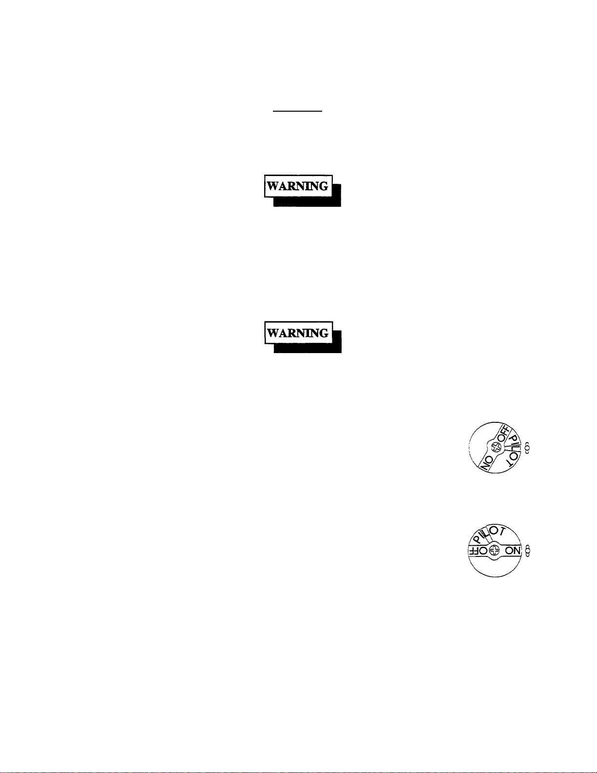
c. Turn the Unitrol valve knob (2) to the PILOT position for the fryer being started, and
push in on the knob. Hold the knob in for approximately one minute to purge the air
out of the line. Hold a flame to the pilot light (3) until the pilot ignites. This may take a
little while the first time you light the fryer because of air in the lines. Once lit, hold
the knob in for approximately 60 seconds and then release.
d. If the pilot goes out wait 5 minutes and repeat step c. If after three tries the pilot will
not remain lit, refer to the operator troubleshooting section of this manual.
e. Turn the Unitrol valve knob counterclockwise to the ON position.
1-8
Page 16
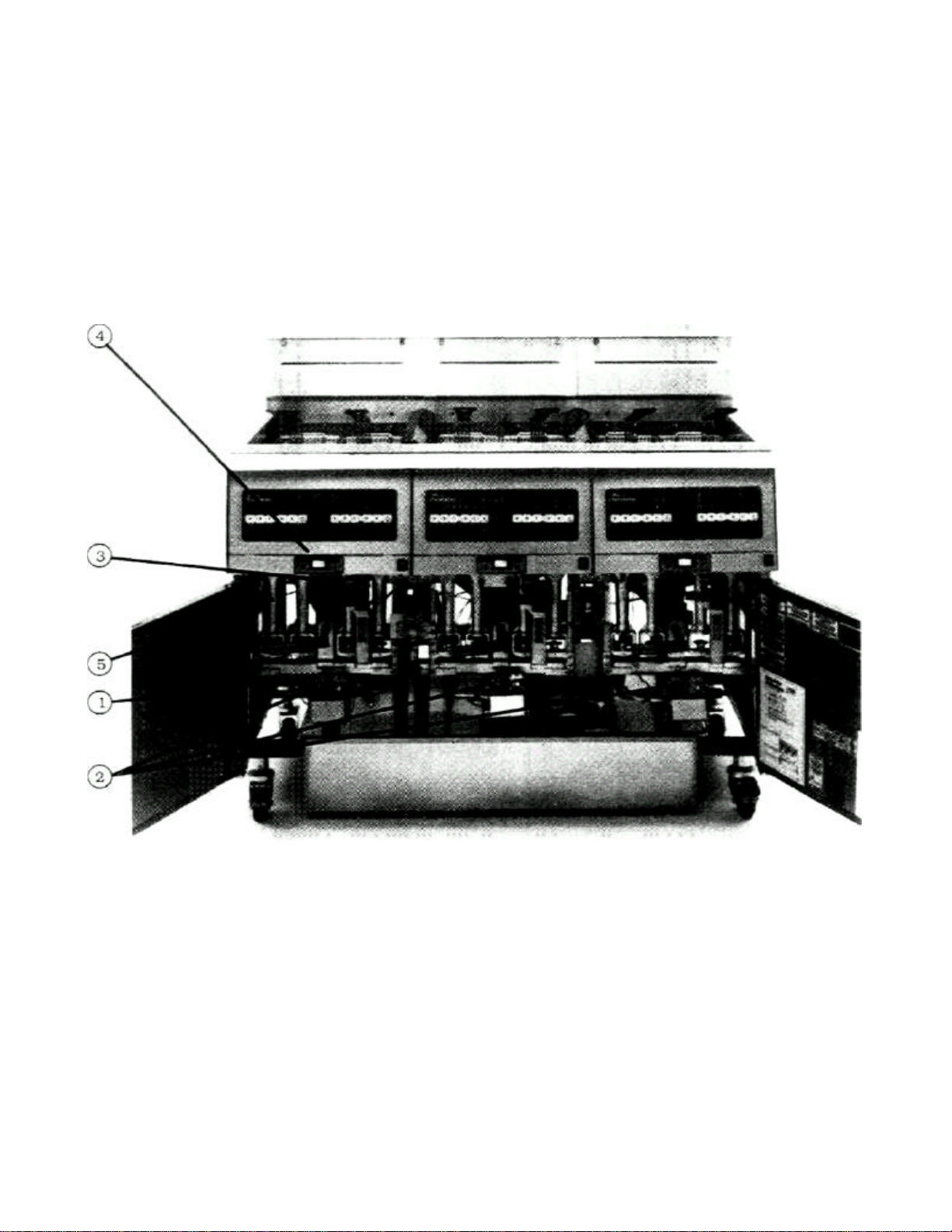
f. Turn the fryer OFF/ON switch (4) to the ON position. The computer display will change from OFF to
MELT (the display may indicate a different condition of the fryer depending on fryer temperature).
g. The main burner (5) will light and be controlled by the computer. The pilot burner will remain lit
regardless of the switch position or computer operation.
h. Refer to the computer operation section for fryer control information.
1-9
Figure 1-1 Inside View of Fryer
Page 17
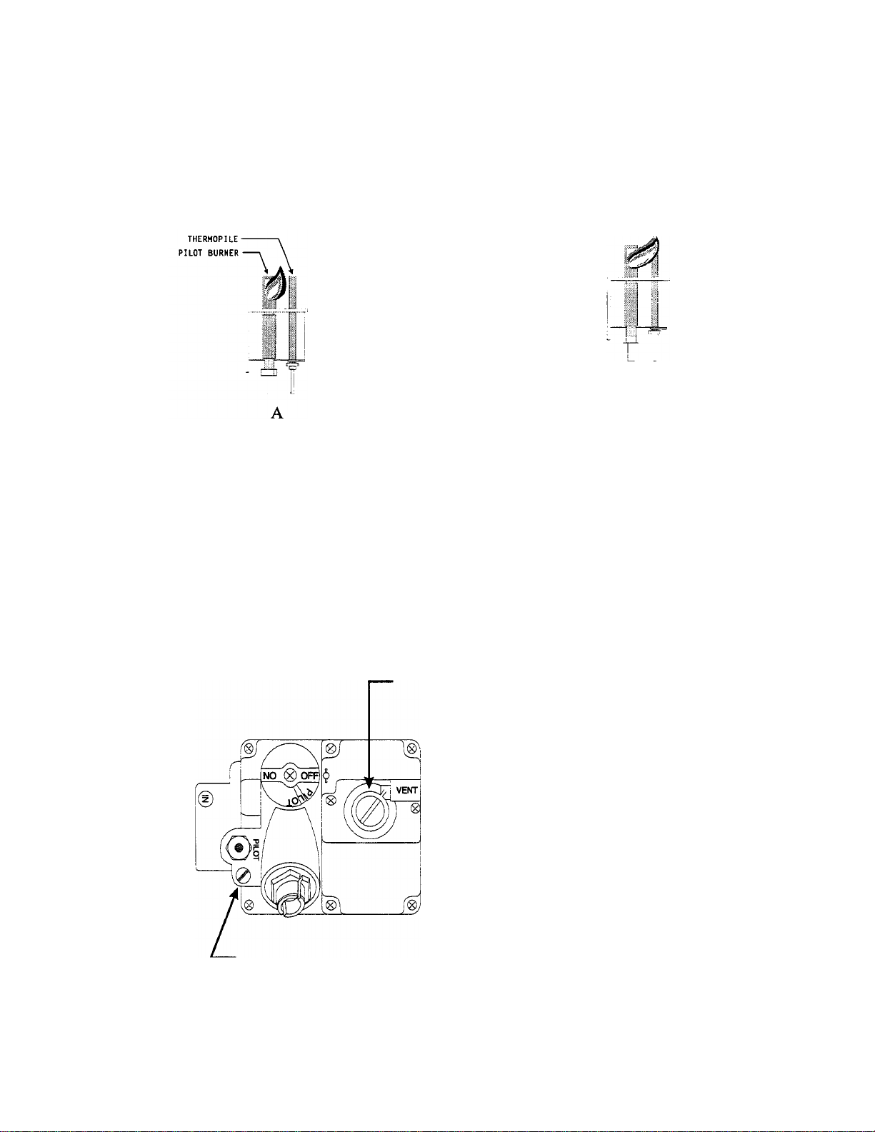
1.4.3 Pilot Flame Adjustment
The pilot flame should be adjusted to produce the proper millivolt output from the pilot sensing device.
Millivolt output for the thermopile should be between 300 and 500 millivolts. Figure 1-3 shows the pilot
assembly with exa mples of the incorrect and correct pilot size. Example A illustrates a pilot flame size that
is too small to produce sufficient millivolt output. Example B is the correct size for proper millivolt output.
B
Figure 1 -2 Pilot Assembly , Flame Adjustment
This test requires a DC millivolt meter set to a scale of 0-1000mv.
a.
Locate the thermopile wires coming from the thermostat/High Limit box
b.
going to the gas shut off valve. The wire insulation size decreases near the
gas valve connections .
c.
Connect the negative (-) test probe to pilot bracket.
Connect the positive (+) test probe to one of the High Limit terminal
d.
connections
PRESSURE REGULATOR LOCATION
(UNDER CAP SCREW)
PILOT ADJUSTER LOCATION (UNDER CAP SCREW)
Figure 1-3 Gas Valve Showing Location of the Pressure Regulator and Pilot Adjusters
1-10
Page 18

e. Light the pilot.
f. Remove the pilot flame adjustment cover.
g. Turning the flame adjusting screw clockwise lowers the flame and the millivolt output.
Turning the screw counterclockwise increases flame size and millivolt output.
h. Rotate the screw in the direction to achieve a reading of 400 ±50 mv for thermopiles.
NOTE
Allow 3 to 5 minutes between flame adjustments to allow the reading to settle.
i. Replace the pilot flame adjusting screw cover.
1-11
Page 19

1.4.4 Main Burner System
For the burners to work the gas supply valve must be open and the main power switch must be on. The main
burner receives gas from the main gas supply through the thermostatically controlled valve. When the
computer calls for flame the gas control valve opens and the pilot light ignites the burners. After the burner
system is operating, perform the burner adjustments in the following procedure. Figure 1-5 illustrates the
different conditions possible for the main burner.
The tubes and baffles are badly
carbonized. Check vent and
adjust if necessary. Check for
heat tube or flue blockage.
The flame seems to "lift off"
the face of the burner. To
correct adjust main burner as
described in
1.4.3.2.
INSUFFICIENT FLOW
Have gas company check
incoming gas pressure. Adjust
manifold pressure as described
in 1.4.3.2.
EXCESSIVE FLOW
A soft, steady blue flame
should enter the heat tube
without touching the front
outside rim of the tube.
INSUFFICIENT GAS PRESSURE
NORMAL FLOW
Figure 1-4 Main Burner Conditions
1-12
Page 20

1.4.4.1 Gas Line Requirements
A properly installed gas supply system will deliver 7.0 ±2.0" w.c. natural gas (11.0 ±2.0" w.c. LP) to all
appliances connected to the line, operating at full demand.
1.4.4.2 Burner Adjustment
The burners must be adjusted to deliver optimum flame. Adjust the burner flame using the following
procedure.
a. Ensure that the gas control valve is in the OFF position. Remove the manifold pressure tap plug and
connect an accurate pressure gauge (range of 0-16" w.c. in 0.1" increments) or manometer.
b. Light the pilot burner (see 1.4.2) for the unit being tested and adjust the thermostat to light the main
burners.
c. The installed pressure gauge reading should be the same, ±0.1", as that marked on the data plate inside
the door. If the pressure is correct go to step e, if not, adjust the pressure.
d. To adjust the pressure, remove the regulator adjustment screw cover. Use a flat tip screwdriver to adjust
the screw until the proper pressure is reached. Turning the screw clockwise will increase the pressure,
counterclockwise will decrease the pressure.
e. When the pressure is correct, install the regulator adjustment screw cover.
f. To remove the pressure gauge, turn gas control valve to OFF. Remove the gauge and install the pressure
tap plug.
Figure 1-5 Air Collar
1-13
Page 21

g. Now that the pressure is set for proper operation, set the main burner flame. Unlock the air collars (see
Figure 1 -5) by loosening the set screw for the collars. Turn the gas control valve to ON and set the
computer to light the main bur ners.
h. Adjust the shape and size by raising or lowering the air collars to achieve a soft blue flame with well
defined inner cones (see Figure 1-4).
i. When the flames have been properly adjusted, lock the collars in place with the set screw provided.
1.5 INITIAL CLEANING
When the fryer is shipped, many of its parts are covered with a thin coat of oil for protection. Before the fryer
is ready for cooking it must be cleaned. This will remove the oil coating and any foreign matter that may have
accumulated during storage and shipment. Perform the cleaning as described below.
a. Fill the tank with water and add one packet of Pitco fryer cleaner or a mild detergent.
b. Turn the fryer on and allow the computer to bring the water to a boil automatically. Allow the fryer to
heat for 15 minutes.
NOTE
Do not leave the fryer unattended during cleaning. Never let the water level go
below the "Min Level" mark on the back of the tank.
c. Using the fryer cleaning brush, scrub the inside of the fryer to remove protective coating.
d. When cleaning is complete, turn off the fryer main burners and turn gas valve knob to the PILOT
position. Drain the water into a container suitable for hot water and dispose of it.
e. When the tank has cooled, rinse it thoroughly with cool water. Continue to rinse the tank until the cleaner
has been rinsed, thoroughly from the tank.
f. Using a clean dry cloth, wipe out all of the water. Be very thorough removing the water, | because any
residual water will cause hot oil to splatter out of the fryer.
CAUTION
Mild steel tanks must be wiped down/coated with oil to keep the tank from
rusting.
g. Now that the tank is clean, you are ready to fill and operate the fryer. Refer to 2.1 for instructions on
adding shortening to the fryer.
1-14
Page 22

CHAPTER 2: OPERATING INSTRUCTIONS
This chapter describes how to operate your fryer to obtain the best performance. Included in this chapter are
filling, operating, and cleaning instructions for gas fryers.
2.1 FILLING THE FRYER
Both liquid and solid shorte ning can be used in the fryer, but liquid is preferred. If solid shortening is used, it
is recommended that you use the solid melt cycle feature built into the computer to melt the shortening.
2.1.1 Filling the Fryer With Liquid Shortening
a. Make sure the drain valve is completely closed.
b. Fill the fryer with oil to the "Oil Level" line marked on the back of the
tank.
2.1.2 Filling the Fryer With Solid Shortening
Never melt blocks of solid shortening on top of the burner
tubes. This will cause a fire, and will void your warranty.
a. Make sure the drain valve is completely closed.
b. Remove the screen covering the tubes.
c. Cut the shortening into cubes no larger than 1". ALWAYS pack the
shortening below, between, and on top of the burner tubes. DO NOT
leave any large air gaps. Use care when packing the solid shortening
in the tank. DO NOT bend or break the temperature sensor probes. If
these are damaged the fryer will not function properly.
d. Once the fryer is packed with shortening, the shortening must be
melted. Shortening melt cycles are controlled completely by the
Intellifry computer. Refer to Fryer Operating procedures for
computer operation.
.
2-1
Page 23

2.2 FRYER OPERATING INSTRUCTIONS
Always observe the safety precautions described in the front of this manual before operating this fryer.
Because fryer operation is controlled by the computer, start-up and operation is very easy. The instructions
below describe how to operate the fryer to perform daily fryer operation. Detailed programming instructions
are provided later in this chapter in section 2.3. Figure 2-1 illustrates the Intellifry computer.
Figure 2-1 Intellifry Computer
2.2.1 Fryer Start -up
Start up the fryer as described in Chapter 1. The computer will come on and display the status of the fryer. If
the shortening temperature is below the set point of the melt cycle the computer will go into one of the preset
melt cycles. When the main burners are on the LEDs in the temperature key will light. If the fryer is operating
in the melt cycle, the temperature key lights will cycle on and off at the preset times. Below is a sequence of
displays that will occur when the fryer is started up with the shortening at room temperature:
1. Turn the fryer on. If a melt cycle is programmed to run, the display will show Melt L or Melt S.
Refer to the programming section 2.3 for selection details.
2-2
Page 24

Melt L indicates that you have the liquid melt cycle programmed to run. Although you do not need to
"melt" liquid shortening, it is a very good idea to heat up all shortening slowly. This will prolong the
life of the shortening and lessen the thermal stress on the fryer tank.
Melt S indicates that the solid shortening melt cycle has been programmed to run. This program will
melt solid shortening and bring the liquefied shortening up to cooking temperature without scorching
the shortening. Refer to the fryer operation manual for solid shortening loading information.
2. When the shortening is above the melt range but below the cooking range the
display will read "Heating". This indicates that the main burners are on steady
and heating the shortening.
3. Once the shortening has reached the cook temperature (Setpoint) the main burners
will turn off and the display will indicate Ready. Ready will be displayed, even
when the main burners are on, as long as the fryer remains in the cooking
temperature range.
* OVER TEMPERATURE - If the temperature of the shortening exceeds the cooking setpoint by 40°F the
display will flash "Hi-Temp" and the alarm will be sounding. Shut down the fryer and allow it to cool down.
2.2.2 Displaying Temperatures
There are two temperatures that the user can select from the computer. Actual and Set. The actual
temperature is the temperature of the shortening and the set temperature is the setpoint that the fryer will
cook at. To display these temperatures perform the followin g:
2.2.2.1 Shortening Actual Temperature:
1. Press and release the "Temperature" key once to display the temperature of the
shortening.
2. The display will show the shortening temperature for three seconds
then return to displaying the fryer status.
3. To continuously display the shortening temperature, press and hold the temperature key. Computers
controlling a single fryer will display the shortening temperature as long as the key is pressed.
2-3
Page 25

2.2.2.2 Cooking Setpoint:
To view the cooking setpoint of the fryer press the Temperature key
twice within one second. The display will change to show the cooking
setpoint for the fryer. The display will hold the setpoint for three seconds
then return to displaying the fryer status.
2.2.3 Display Product Times
Each product button has three times associated with it, cook, shake, and hold. Cook time is the total time the
product is to be cooked. The shake time is the length of time before the end of the cook cycle that the beeper
will sound to indicate you should shake the product. After the product has finished cooking it can be held for
a certain amount of time before it should be replaced with fresh product. This time is called the hold time. To
view the times associated with each product key perform the following:
NOTE
You can only perform this procedure when the product key is not in
a cook or hold cycle.
2.2.3.1 Viewing Product Times:
1. View the product times by first pressing the Time key and then the
product key you want to check.
2. The display will change to show the time for each of the three
changeable times. The illustrations show how the product times
will be displayed. Each time setting will be displayed for three
seconds before changing to the next one. After the last time is
displayed for three seconds the display will return to fryer status
display.
CK Indicates Cook Time (Product key LED blinks rapidly during cook cycle)
SH Indicates Shake Time
HD Indicates Hold Time
2.2.4 Cooking Product
Cooking with the computer is very easy. Select the product button to use and press it. The computer does the
rest. The discussion below shows each step in the cooking process.
1. Press the product key for the product bein g cooked. The product key
LED will blink rapidly and the display will show the product cook
time and start counting down.
2-4
Page 26

2. When the shake time is reached the buzzer will sound and the display will display shake. The buzzer
(beeps slowly) will sound for a short time and then cancel itself.
3. The product will continue to cook until the cook time has run out. When the cook time is up the buzzer
will sound again (rapid beeping) and the product key LED will blink slower to indicate that the product is
finished cooking. Press the product key to silence the buzzer and lift the product out of the shortening.
4. The product key LED blinks slowly during the hold time and the display will show the remaining hold
time.
5. When the Hold time is up the buzzer will sound again (beep very slowly) . After a short time the product
key light will go out and the buzzer will stop.
2.2.5 Shutdown
There are two shutdown modes of fryer operation, STANDBY and COMPLETE. The standby mode removes
the ability for the fryer's main burners to cycle. Complete shutdown turns off the gas supply to the fryer. Shut
down the fryer by:
STANDBY Turn fryer switch to OFF. The computer display will indicate OFF. Turn the
gas valve knob clockwise to the PILOT position. The fryer is now in
Standby and can remain this way for only brief periods of time. NEVER
leave the cooker in standby overnig ht.
COMPLETE To completely shut down the cooker, turn the gas valve knob clockwise to
the PILOT position. Depress the knob slightly and turn it to the OFF
position. The fryer is now completely shut down and can be cleaned and
filtered.
2.2.4 Power Failure
NOTE
No Attempts should be made to operate the fryer during power outages.
If power is removed from the fryer for any reason during operation, the unit will shutdown. Wait five minutes
after power is restored before restarting the fryer. This will give any gas fumes in the burner time to dissipate.
To restart the unit, follow the Start-up procedure as you normally would.
2-5
Page 27

2.3 PROGRAMMING THE INTELLIFRY COMPUTER
1. Press the Program key
If no password is programmed the display will indicate
There are three levels of programming for the new computer, user, service, and factory. Each level allows
for different degrees of computer control. Only the user level of programming is discussed in detail in this
section. The service and factory levels of programming deal with the configuration of the computer and
require an additional password to enter. The user programming section is broken down into two section
basic and infrequent.
2.3.1 Basic Programming
There are only two items that will be changed on a routine basis, shortening temperature and product times.
If a password is programmed you must enter the password to change the program in the computer.
2.3.1.1 Programming Shortening Temperature
NOTE
Skip step one if you are still in the program mode from a previous procedure. By remaining in
the program mode you will not need to reenter the password.
PROGRAM. If a password is required the display will change to PASS_ _ _ _indicating that you
must enter the password. Enter the password to access the user level programming mode.
2. Press the Temperature key . The current set temperature
will be displayed. If the current temperature setting is correct
press the Program key return to the programming mode.
3. Enter the new shortening temperature by pressing the product number keys for the desired
temperature. For instance if you want the new te mperature to be 350°F, you would press the 3, 5,
and 0 product keys.
4. The new temperature will be shown in the display. To exit the temperature program and save the new
setting press the Program key You will still be in the user programming mode.
You can go to the next item to be changed or exit the programming mode. To exit the programming
mode press the Program key again.
2-6
Page 28

2.3.1.2 Programming Product Times
NOTE
Skip step one if you are still in the program mode from a previous procedure.
By remaining in the program mode you will not need to reenter the
password.
1. Press the Program key. The display will change to PASS_ _ _ _indicating that you must enter
the password. Enter the password to access the user level programming mode.
NOTE
You can review the set times without making changes by pressing the
time key to advance through the settings after a product key is
selected. You can return to the programming mode any time by
pressing the Program key
2. Press the Time key . All of the product key LEDs will light up. Press the product key
that is to be changed and the display will show the cook time for the product. Enter the new cook time
using the product number keys. A maximum of 99:99 can be entered. After entering the desired time
press the Time key to accept the new setting. To set the shake
time go to step 3. To exit the time set program press the Program key to return to the program
mode.
3. Press the Time key to set the shake time. The display will change to show the current shake
time. Enter the new shake time using the product number keys. A maximum of 99:99 can be entered.
After entering the desired time press the Time key to accept the new setting. To set the
hold time go to step 4. To exit the time set program press the Program key to return to the
program mode .
4. Press the Time key to set the hold time. The display will change to show the current hold
time. Enter the new hold time using the product number keys. A maximum of 99:99 can be entered.
After entering the desired time press the Time ke y to accept the new setting. When
the Time key is pressed you will be returned to the beginning of the time set program.
To set another product key repeat steps 1 through 4. To exit the time set program press the Program
key to return to the program mode.
2-7
Page 29

2.3.2 Low Level Programming
In addition to the basic programs there are a number of low level programs. These functions are used to set
the features of the computer that do not need to be changed often. These functions are:
• Temperature System °C or °F
• Password
• Volume
• Language
• Melt Cycle Setting
• Recovery Test
• Computer Control Mode
To enter the lower level programming level and change the desired function, use the procedure for the
function to be changed.
2.3.2.1 Temperature display
To toggle between °C and °F use the following procedure:
1. Press the Program key and enter the password (if a password is programmed). If you
are still in the low level programming mode from a previous procedure you will not need to enter the
password.
2. Press the zero (0) product key. The display will change to show "SELECT".
3. Next press the one (1) product key to enter the temperature program. The display will indicate the current
temperature units "DEGREE F" (DEGREE C).
4. To change the temperature units press the zero (0) product key. The display will alternate between
"DEGREE F" and "DEGREE C" each time the zero (0) key is pressed.
5. To exit the temperature display setting program press the Program key to return to the
program mode. To exit programming mode press the Program key again.
2.3.2.2 Password
To set a new password or remove the password follow the procedure below:
1. Press the Program key and enter the password (if a password is programmed). If you
are still in the low level programming mode from a previous procedure you will not need to enter the
password.
2-8
Page 30

2. Press the zero (0) product key. The display will change to show "SELECT".
3. Next press the two (2) product key. The display will indicate "SET PASS".
4. To turn the password requirement on or off press the zero (0) product. When the display
indicates "NO PASS" a password is not required to enter the program mode. A display of
"PASS RERQ" indicates that a password is required to enter the programming mode.
5. To enter a new password (or display the current password), press the Program key . The
display will change to display the current password "PASS####" where the current password
would display in the place of the ####.
6. While the "PASS####" is being displayed you can change the password. Use the key pad
to enter any four numbers. After the new password has been entered (or to exit viewing
the current password) press the program key to return to the program mode.
7. To exit the programming mode press the program key again.
2.3.2.3 Beeper Volume
To set beeper volume, follow the procedure below:
1. Press the program key and enter the password (if a password is programmed). If you
are still in the low level programming mode from a previous procedure you will not need to
enter the password.
2. Press the zero (0) product key. The display will change to show "SELECT".
3. Next press the three (3) product key. The display will change to indicate "VOLUME #". The
# will be replaced with the current setting for the beeper. There are three settings for beeper
volume, one (1) being the softest and three (3) the loudest.
4. To toggle through the beeper volumes press the zero (0) product key. Each of the volume
settings will be displayed as the zero (0) key is pressed and the beeper will sound to provide
an example the volume.
5. After selecting the desired volume, (or to exit viewing the current volume setting) press the
program key to return to the program mode.
5. To exit the programming mode press the program key again.
2-9
Page 31

2.3.2.4 Languages
To set the language that will be displayed follow the procedure below:
1. Press the program key and enter the password (if a password is programmed). If you
are still in the low level programming mode from a previous procedure you will not need to
enter the password.
2. Press the zero (0) product key. The display will change to show "SELECT".
3. Next press the four (4) product key to enter the language program. The display will change
to indicate "ENGLISH" or the current language.
4. To toggle through the available language settings press the zero (0) product key.
5. To exit the language setting program press the program key once. To exit the low level
programming menu press the program key again.
2.3.2.5 Melt Cycle
To select the melt cycle desired follow the procedure below:
1. Press the program key and enter the password (if a password is programmed). If you
are still in the low level programming mode from a previous procedure you will not need to
enter the password.
2. Press the zero (0) product key. The display will change to show "SELECT".
3. Next press the five (5) product key to enter the melt cycle program. The display will change
to indicate "SOLID" or the current melt setting.
4. To toggle through the three available melt cycle settings press the zero (0) product key. Each
of the settings (NO MELT, LIQUID, or SOLID) will be displayed as the zero (0) key is
pressed.
5. After selecting the desired melt cycle, (or to exit viewing the current setting) press the
program key to return to the program mode.
6. To exit the programming mode press the program key again.
2-10
Page 32

2.3.2.6 Recovery Test
To view the recovery test data follow the procedure below:
1. Press the program key and enter the password (if a password is programmed). If you
are still in the low level programming mode from a previous procedure you will not need to
enter the password.
2. Press the zero (0) product key. The display will change to show "SELECT".
3. Next press the six (6) product key to enter the recovery test program. The display will
change to indicate "RECOVERY".
4. To display the recovery test data press the six (6) key again. The display will change to
display the recovery test data (F###L###).
5. The display indicates the time it took the fryer to heat up from 250°F to 300°F at the factory
and the last time the recovery test was performed. The F### portion of the display
indicates the time in seconds that the fryer took to heat up at the factory. The L###
indicates the heat up time in seconds the fryer took the last time the test was performed.
6. After viewing the recovery test data press the program key to return to the program
mode.
7. To exit the programming mode press the program key again.
2.3.2.7 Computer Control Mode
The computer can be switched from control mode to timer mode. In timer mode the computer
does not control the fryer. To change the computer mode from control to timer follow the
procedure below:
1. Press the program key and enter the password (if a password is programmed). If you
are still in the low level programming mode from a previous procedure you will not need to
enter the password.
2. Press the zero (0) product key. The display will change to show "SELECT".
3. Next press the seven (7) product key to enter the computer control program. The display will
change to indicate "CONTROL" or "TIMER".
4. To toggle between the two modes of control press the zero (0) product key. Each of the
settings (CONTROL or TIMER) will be displayed as the zero (0) key is pressed.
2-11
Page 33

5. When "CONTROL" is displayed the computer has complete control of the fryer. When
"TIMER" is displayed, the computer acts only as a timer.
NOTE
When the computer is in TIMER mode the display will indicate "TIMER"
during normal operation of the fryer.
5. After selecting the desired control mode, (or to exit viewing the current setting) press the
program key to return to the program mode.
6. To exit the programming mode press the program key again.
2-12
Page 34

2.4 SHORTENING FILTER PROCEDURES
This section describes the procedures used to filter the fryer. Figure 2-2 shows the
locations of the components used in the filter process. The filter accessories and
tools you should have to perform normal filtering operations are described after
Figure 2-2. The illustrations used with the filter procedures are provided to show
where the oil is going and which valves are open. Frequent filtering of your
shortening will prolong the shortening's usable life. Daily shortening filtering is
strongly recommended.
NOTE
See Maintenance Section for Filter Operational
Information.
Figure 2-2 Fryer Illustrating Filter Components
2-13
Page 35

(1) Return Valve(s) RED - When open, with the filter pump on, allows the shortening to return to
the fryer tank.
(2) Unit Drain Connection YELLOW - Quick disconnect and valve for optional flush hose.
(3) Drain Valve(s) GREEN - Drain the oil from the fryer tanks to the filter pan.
(4) Oil Return Connection - Quick disconnect for return oil from the filter unit to the fryer.
Simply push down on fitting to connect. Lift up lower black collar to disconnect.
(5) Filter Media - Long lasting filter media. Filter paper envelopes.
(6) Filter Crumb Scoop - Short handle wide pan design, this scoop is used to remove the debris
from the filter pan.
(7) Cleaner - Used during fryer boil-out cleaning.
(8) Drain Clean Out Rod - Long handled design, this tool is used to clean out the drain openings.
(9) Precoat Filter Aid - Coarse Diatomaceous earth used to enhance the filter ability of the filter
media.
(10) Cleaning Brush - This long handled stiff bristle brush is used to brush down the crumbs
inside the fryer tank during shortening filtering.
(11) Fryer Crumb Scoop - A specially designed long handle scoop for scooping out the fryer. The
scoop section is narrow enough to fit down between the fryer burner tubes.
(12) Precoat Measuring Cup - Marked in ounces for correctly measuring precoat to be added to
the shortening prior to filtering.
At operating temperature the shortening temperature will be greater than
3OOF. Extreme care should be used when filtering operating temperature
shortening to avoid personal injury.
2-14
Page 36

2.4.1 General Filter Hints
1. Ensure that all oil in the filter pan is returned before it cools and hardens. This is very
important if you are using solid shortening.
2. Always use Pitco Precoat® for fastest filtrations, maximum labor saving, and cleanest/
clearest shortening possible. Impaired filter performance will result without the use of a filter
aid.
3. The longevity of your oil is related to how clean you keep it. With a Pitco built in system, it is
easy to do a quick drain/refill anytime. By removing suspended particles often, it prevents
them from burning.
4. When the time it takes to refill the fryer after filtering exceeds 3:00 minutes per tank, scrape
the filter media. If scraping does not bring the refill time back down to less than 3:00 minutes,
thoroughly clean the filter media and replace as necessary.
5. The filter pump is protected from clogging by a special screen in
the pickup tub. Clean this screen thoroughly each time the filter is
cleaned or new filter media is installed (see Chapter 3).
6. If you have filter system problems refer to section 3.7.3.
7. Always check to ensure that the oil return line is connected securely
before filtering.
2-15
Page 37

2.4.2 Filter Procedures
Numbers in parenthesis refer to Figures 2-1 and associated text.
NOTE
• When working with hot oil ALWAYS wear oil-proof, insulated gloves.
NEVER
• Run the filter system without a filter bag/paper.
• Empty the oil from the fryer before turning OFF the fryer burners.
• Store the UFM Filter Unit anywhere other than in the fryer filter cavity.
a. Disconnect the filter pan, slide it out. Scrape previously filtered residue off the filter media.
Examine the filter media for clogged or torn areas. Refer to 3.1.1 for filter media replacement
instructions. Reinstall the pan.
b. Turn the fryer that is to be filtered OFF (See Standby Shutdown). Remove the baskets from
the fryer tank(s). Use the clean out rod (8) to lift out the tube screens. If there are excess
crumbs in the fryer tank, remove them with the crumb scoop(l 1).
c. If you have replaced or scraped the filter media, stir in Precoat Filter Aid (9) to the oil in fryer
(2 packets per fry tank being filtered). After cleaning out the excess debris with the fryer
scoop (11) sprinkle the powder into the first fry tank to be filtered and stir the powder into the
oil.
d. Check the drain spout to ensure that it is over the filter cover opening. Adjust the cover or
slide the filter pan as necessary to line up the drain and the cover opening.
e. Slowly open the green handled drain valve (2) for the tank being filtered. If necessary use the
clean -out rod (8) to clear the crumbs from the drain. Use the long handled brush (10) to clean
the sides of the tank as the oil drains.
NOTE
This filter pan is large enough to filter all three tanks at once.
f. When the tank is empty, close the green handled drain valve. Open the red handled return
valve (1) to the tank you are filtering. This will start the pump and return the oil to the bottom
of the fry tank. As the tank fills, brush the inside of the tank to remove crumbs.
g. When bubbles are seen coming out of the oil return spout, close the red handled valve to turn
the pump off. Open the green handled drain valve (2) and allow the tank to drain again. Repeat
steps b through d until the tank is clean.
2-16
Page 38

h. When the tank is clean, drain the shortening by opening the green handled drain valve (2).
With the drain valve open, open the red handled return valve (1) and allow the shortening to
circulate for approximately 2 minutes. This ensures that all impurities are removed from the
shortening.
i. Close the red handled return valve to turn off the pump. Close the green handled drain valve
and replace the tube screen in the fry tank.
j. Open the red handled return valve (1) and turn on the pump to refill the fryer with the filtered
oil. Continue to run the filter pump until bubbles come out the oil return opening. Close the
red handled valve to mm the pump off. If necessary add more oil to the tank to return the oil
level to the fill mark. The fryer is now ready for use.
2.4.3 Draining a Tank
The filter system is also used to drain the fryers. You will need the Shortening Shuttle® that came
with the fryer to perform this procedure. This procedure can be used in conjunction with the filter
procedure (2.6.2). Instead of performing step (j) of the filter procedure perform the procedures
below.
The Shortening Shuttle® only hold enough oil to accommodate one fry
tank at a time.
a. Move the Shortening Shuttle® to the front of the fryer close enough to connect the hose to
the drain outlet.
b. Connect the male quick disconnect fitting of the Shortening Shuttle® to the female quick
disconnect of the fryer. There is a yellow handled valve associated with the fryer drain quick
disconnect. Ensure that the hose is firmly connect to the fryer.
c. Open the green handled drain valve for the tank to be drained. The oil will drain to the filter
pan. When the fry tank is empty close the green handled drain valve.
d. Open the yellow handled discharge valve. This will start the pump and pump the oil from the
filter pan to the Shortening Shuttle®.
e. When the filter pan has been pumped out, close the yellow handled discharge valve.
Disconnect the Shortening Shuttle® hose from the fryer. Fill the fry tank with fresh oil and
restart the fryer.
2-17
Page 39

CHAPTER 3: OWNER MAINTENANCE AND ADJUSTMENTS
This chapter provides you with the information and procedures necessary to perform maintenance,
adjustments, and service on the Wendy's W 14S-3 WF fryer. If after performing maintenance on your
fryer it does not perform properly, contact your authorized service center.
The power supply must be disconnected before servicing or cleaning the
appliance.
3.1 FILTER MEDIA REPLACEMENT
The filter module stores neatly under the fryer when not in use. The unit is very easy to use and
allows for quick installation and filtration, even under the busiest conditions. Follow the procedures
below to change the filter media.
At operating temperature, the shortening in the fryer may be hotter
than 375°F (190°C). This hot, melted shortening will cause severe
bums. Do not let the hot shortening touch your skin or clothing.
Always wear insulated oil-proof gloves when working on the filter
system. It will be easier and safer if the filter assembly has cooled to
room temperature before handling any filter parts.
a. To remove the filter media, disconnect the filter tube pick-up from the fryer. This is done by
unscrewing the pick-up tube connector from the fryer connector.
b. Grasp the filter pan handle and gently pull the assembly toward the front of the fryer. When
the pan is clear of the fryer, remove the filter pan cover.
c. Discard any debris that may be in the crumb
catch.
d. Lift up on the filter paper assembly and
remove from the filter pan. Unscrew the
suction tube from the filter paper support
rack. Remove the clip screen and slide the
filter paper support rack assembly out of the
filter bag.
3-1
Page 40

e. All of the filter pick up assembly parts can be washed in a dish washer or
a pot sink. Flush out the suction tube assembly with hot water. The pick
up tube screen keeps grit and solid material from binding the pump. After
flushing the pick up tube screen check to ensure that the screen is free of
debris. After cleaning, it is very important to thoroughly dry the parts
before re-assembling. Water and oil do not mix. Water in hot oil will
cause the oil to splatter.
f. Start re-assembling the filter pick up assembly by sliding the new filter
paper on to the filter paper support rack. Ensure that the hole in the filter paper goes
over the pick up tube assembly threaded connector.
g. Fol d the open end of the bag in two folds. The
first fold should be approximately 1 inch from
the end and the second should be over the edge
of the rack assembly. Approx. One Inch
h. Slide the clip screen over the folded
end of the filter paper. Ensure the opening of the
clip screen goes over the pick up tube connection.
Screw the suction tube assembly onto the threaded
connection.
i. Slide the filter pan assembly back into the filter unit and attach the pick up tube
connector to the filter unit connection.
3-2
Page 41

3.2 FRYER CLEANING
3.2.1 Daily
Your fryer should be clean every day to maintain peak performance and appearance. Perform the
procedures below every day.
a. Wipe up any shortening that spills onto the exterior of the fryer. This should be done with a
clean soft cloth while the oil is still warm.
b. Use warm water with a mild detergent to clean surfaces. Be careful not to get water in the
shortening and to remove any detergent from the fry tank.
c. Use a nonabrasive scouring powder or pad to clean stains if necessary.
3.2.2 Weekly (Boilout)
The fryer should be thoroughly cleaned once a week. This cleaning should include a complete
draining of the fryer and a boil out. This would also be a good time to check the filter media for
damage.
CAUTION
Completely shut down the fryer when the oil is to be replaced by
water, and when the heating portion of the cleaning is complete. This
will prevent the heating system from coming on during the oil draining
and water filling procedure.
a. Drain the oil from the fryer using the fryer drain procedures in chapter 2. When the oil has been
pumped into the oil shuttle, disconnect the filter pan and remove from the fryer.
Do not use the filter pan to drain cleaning water into. The only way to
remove liquid from the filter pan is via the filter pump. Do not use the
filter pump to pump water. Water can remain in the filter lines and mix
with hot oil during filter procedures creating a problem.
b. Remove tube rack/mesh tube screens and remove any large debris from the bottom of the fry
tank. Close the drain valve and fill the fry tank with water and noncaustic detergent. For best
results use Pitco Fryer Cleaner part number P6071397.
c. Place a large pan under the drain. This pan will be used to catch the cleaning water. The pan
must be of sufficient size to hold all of the water.
3-3
Page 42

d. Restart your fryer as described in 2.3. When the water temperature reaches 212°F the computer
will automatically go into Boil mode. To get the fryer out of BOIL mode you must turn the
fryer power off.
e. After the water has reached a slow boil, turn the fryer off. Allow the fryer to soak for 20
minutes to soften shortening deposits and carbon. Use fryer brush to remove any residue from
tank, heating tubes, and side walls. Perform the daily cleaning procedure described in section
2.5.
f. Drain the water into the pan by slowly opening the green handled drain valve.
g. Wipe the tank dry with clean cloth wipes. Close the drain valve and remove the large container.
h. Refer to section 2.1 to refill the fryer.
3.3 FLUE AND BAFFLE INSPECTION
It is recommended that once every six months, with the cooker cooled down, you examine the flue
area. Check for corrosion or blockage of the flue. Ensure that the cooker is shutdown and do not
turn it on during the examination. Examination of the flue area during cooking may cause bodily
i njury.
3.4 SERVICE
This chapter provides the qualified technician with the replacement and troubleshooting procedures
necessary to service the Pitco fryer.
3.4.1 Replacement Procedures
These procedures are provided to the qualified technician as a guide to removal and replacement of
various fryer components. If a test is required to verify component operation after installation, it
will be referenced.
To prevent bums, always ensure the fryer is completely SHUT DOWN and
COOLED down before working on the fryer. Do not break any fryer gas
connections while the unit is connected to a gas supply line.
The power supply must be disconnected before servicing or cleaning the
appliance.
3-4
Page 43

3.4.1.1 Main Burner Removal and Replacement
a. Loosen the set screw in the base of the burner casing.
b. Unscrew and remove the two hex head screws at the top of the burner.
c. Loosen the set screw on the air collar. Lift the burner and air collar up to clear the top of the
burner fitting. Remove the burner from the fryer.
d. To re-install the burner, reverse the procedure.
3.4.1.2 Changing the Main Burner Orifice
a. Unscrew the orifice with a 3/8" wrench and remove the orifice.
b. Insert the new orifice and tighten with the 3/8" wrench. Ensure the orifice is tight enough to
prevent gas leakage around the orifice.
3.4.1.3 Replacing the Heat Baffles
a. Remove the Main Burner as described in 3.4.1.1.
b. The heat baffles are located inside the heat tubes. They are attached to the rear of the baffle
supported by tack welds. Using a chisel, break away the baffle support and remove the old
baffles. Be careful not to puncture the heat tubes because this will require complete tank
replacement.
c. Insert the new baffles in the tubes in the original position. The new baffles sit in position and
do not require welding.
d. Install the main burners.
3.4.1.4 Pilot Burner Removal and Replacement
a. Unscrew the tubing nut from the pilot tubing connection at the gas valve. Disconnect the
thermopile from the connection on the gas valve.
b. Unscrew and remove the two screws that attach the pilot assembly to the fryer tank. Lift the
entire pilot assembly out of the fryer.
c. To replace the pilot assembly, reverse the procedure.
3.4.1.5 Pilot Orifice Replacement
a. Remove the pilot assembly as described in 3.4.1.4.
3-5
Page 44

b. Unscrew the tubing nut from the pilot tubing connection at base of the pilot burner. The pilot
orifice is located inside the tubing connection.
c. Remove the orifice and replace with the new orifice. Ensure the orifice is tight enough to
prevent gas leakage around the orifice.
d. Replace the tubing nut in the pilot tubing connection and tighten enough to prevent gas
leakage.
e. Replace the pilot assembly and adjust the pilot flame as described in 1.5.2.
3.4.1.6 Thermopile Replacement
a. Remove the pilot assembly as described in 3.4.1.4.
b. Unscrew and remove the thermopile from the pilot assembly.
c. Remove from gas valve magnet.
d. Insert the new thermopile in the pilot assembly.
e. Replace the pilot assembly and adjust the pilot flame as described in 1.5.2.
3.4.1.7 Limit Control Replacement
The limit control includes a temperature sensor inside the fryer tank, control unit inside the fryer
cabinet, and connecting capillary tubing. The high limit control temperature sensor looks like the
thermostat temperature sensor, so ensure you are removing the correct temperature sensor clamp.
CAUTION
The limit control capillary tubing is very delicate. Be VERY
CAREFUL when working with the capillary tubing. If the tubing is
kinked or broken the limit control is no longer usable.
a. Drain the oil from the fryer and remove the heat tube screens.
b. The limit control probe (heat sensor) is clamped to the heat tube inside the tank. Unscrew and
remove the two screws in the probe clamp.
c. Remove the probe from the clamp and straighten the capillary tubing. Unscrew the small hex
nut inside the cabinet at the bottom of the tank for the limit control.
d. Unscrew the large connector nut from the tank and pull the probe and capillary tubes through
the opening.
3-6
Page 45

3.5 TROUBLESHOOTING
This section is provided to aid you in the event of fryer or filter troubles. If these troubleshooting
procedures do not correct your problem contact a qualified technician or the factory. The
troubleshooting procedures are in a flowchart format.
3.5.1 Fryer Troubleshooting
Refer to this section to correct common problems that may be encountered in equipment operation.
3-7
Page 46

3.5 TROUBLESHOOTING
This section is provided to aid you in the event of fryer or filter troubles. If these troubleshooting
procedures do not correct your problem contact a qualified technician or the factory. The
troubleshooting procedures are in a flowchart format.
3.5.1 Fryer Troubleshooting
Refer to this section to correct common problems that may be encountered in equipment
operation.
3-8
Page 47

Page 48

Page 49

Page 50

CHAPTER 4: PARTS
This chapter contains listings of the components used in the Wendy's model W14S-3 WF fryer.
These components are listed in two places, with the illustration and in ordered part lists. The
illustrations in this chapter are provided to show relative location of component of the fryer. With
each illustration there is a table of components in numerical order by illustration number. The
illustration has numbered lines pointing to components which are listed in the table.
At the end of this chapter there are alphabetical and numerical listings of all parts used in the fryer.
The alphabetical part list is arranged in alphabetical order according to the part name. Each part
name also has the Pitco Frialator part number. The numerical list is in Pitco Frialator part number
order. A brief description of each component is provided for each part.
4-1
Page 51

Table 4-1 Wendy's Model W14-3UFM Exploded View (Index)
Index Number
1 Tank, Weldment W/RR NIP 52 Handle, Valve Weldment
2 Clamp, Probe Temperature 53 Aces, Switch Drain Valve Interlock
3 Clamp, Bulb Limit Pasta 54 PG, Bracket Manifold Sprt 14
4 Tank Fitting, NIP Drain Ext 55 Screw, 10-24 x 1/2 HHC SS
5 Tank, Bracket Spacer Overflow 56 Washer, Flat #10
6 Valve, Ball 1-1/4" Drain Full Port 57 Screw, 10-24 x 1/2 Thumb W/S
7 Tank, Overflow Tubing Weldment 58 Connector, Thermocouple SS
8 Clamp, U-Bolt 1/4 -20 x 1-1/8 59 PG, Cir Air, 7,12,12D,14,14C+,14R,18
9 Probe, Thermistor Gas 60 Switch, Rocket SPST W/BK (1-1)
10 FL, Weldment 14 HRPO 61 Handle, Drain Spacer
11 Tank, BK SPLH Weldment 62 Cabinet Bk, Bracket Relief Valve
12 Cabinet, Frame Weldment 63 Entrance Box, Assy Left
13 Cabinet, Side, Right Hand 64 Entrance Box, Assy Middle
14 Cabinet, Side, Left Hand 65 Entrance Box, Assy Right
15 Cabinet, Back, Top 66 Label, Sheet Gas 7,14,18,14R,14C+
16 Cabinet, DR Bumper Assy 67 Label, Overlay Pump Circuit Breaker
17 Front Panel, Rail Bottom 68 Label, Drain Handle
18 Front Panel, Cap End Left Hand 69 Label, Discharge Valve
19 Front Panel, Cap End Right Hand 70 Label, Return Valve Handle
20 Front Panel, Intermediate SPRT Weldment 71 Label, Quick Filter Instruction
21 Front Panel, Bezel Weldment 72 Label, Switch ON-OFF
22 Cabinet, DK Front Weldment 73 Label, A-F
23 Computer, EP 3600 14 Single (TDI) 74 Schem, Label
24 DR, Assy, Right Hand 75 Handle, Valve 24R.18WKS, E147UFM
25 DR, Assy, Left Hand 76 Pin, Clevis 1/4 x 2-1/4
26 Hinge, Pivot Vertical Bracket Top RH 77 Pin Cotter 1/16 x 3/4 ZN
27 Hinge, Pivot Vertical Bracket Bottom LH 78 Grommet 0-19 ID x 1.13 OD x 0.88 GRV
28 Hinge, Pivot Vertical Bracket Top LH 79 Screw, 1/4 -20 x 1 HHC SS Full Thread
29 Hinge, Pivot Vertical Bracket Bottom RH 80 Nut, Hex (KEP) 1/4 -20 ZN
30 Caster, Swivel, 7" Locking Polyu 81 Electric Assy, Power Cord
31 Caster, Swivel, 7" Nonlocking Polyu 82 Clip, U, Spring Steel 0.10-0.16
32 Burner, Pitco 4" 83 Screw, 10-32 x 1/2 PHN ZN TF
33 PG, Manifold Assy, Nat 84 Box, Electrical 4 x 2-1/8 x 1-7/8
34 PG, Pilot Assy Nat 85 Cover, Box, 4x2
35 PG, Sprt Flush Hose 86 Screw, 1/4 -20 x 2-1/4 HHC ZN
36 PG, Sply Gas RR 87 Screw, 1/4-20 x 1/2 HHC SS
37 PG, Brkt Sprt Gas Manifold 88 Screw, 5/16-18 x 3/4 HHC SSBB
38 Filter, Handle Return Assembly 89 Washer, Lock 5/16 ZN (Split)
39 Filter, Bracket Handle Actuator 90 Screw, 10-32 x 1/4 Set SH Cup Pt
40 Filter, PG Return Assy 91 Wrg, Valve 24V GBB Non-EI
41 PG, Out Discharge Assy 92 Nut, Hex (KEP) 10-24 ZN
42 Hi-Limit Switch Assy 93 Screw, 10-24 x 5/8 RDH Phillips SS
43 Gasket, Drain Line (Sleeve) 94 Nutsert 10-24 (AVDEL)
44 Filter, Pan Weldment 95 Label, Overlay P/Matic 14 Clear Prot
45 Filter, Lid Weldment 96 Tank, Shield, Burner Bracket, Heat 14 L
46 Filter, Bracket SW 97 Tank, Shield, Burner, Bracket Heat 14 R
47 Front Panel, Intrmed Sprt Weldment L 98 Label, Caution Yellow
48 Filter, Tube Suction Assy 99 Label, Reset Button Horizontal
49 Filter, Rack Weldment 100 Ship Kit, W1'4-3UFM Wendy's (N/S)
50 Filter, Screen, Clip 101 Filter Envelope 20.5 x 14.344 Center Hole
51 Filter, Air RLF Assy
Description Index Number Description
Page 52

NOTES.
1. ITEMS NOT SHOWN FOR CLARITY:
#58 P5045047 - CONN, THERMOCOUPLE SS QTY 3.
#59 A8001001 - COLLAR, AIR QTY 12.
ALL LABELS, REFER TO DWG B60-OS9 FOR LOCATIONS AND PART NUMBERS.
ALL HARDWARE.
Figure 4-1 Wendy's Model W14S-3WF Exploded View 4-3
Page 53

4-4
Page 54

ALPHABETICAL PART LIST
Part Description
BRUSH, FRYER CLEANING PP10056
BURNER, MAIN "A" 4" P6071050
CASTER, 7" LOCKING PP10883
CASTER, 7" NON-LOCKING PP10884
CLAMP, U-BOLT PP10891
CLEANER, FRYER SAMPLE PACKET P6071400
COLLAR, AIR - SET SCREW TYPE A8001001
COMPUTER, EPS 600, 14 SINGLE (TDI) PP10804
DOOR ASSEMBLY - LH B2301902
DOOR ASSEMBLY - RH B2301902
DRAIN VALVE HANDLE B4000801
FILTER PAN B6632701
FILTER PAN LID B6632801
FILTER RACK ASSEMBLY B6620002
FILTER SCREEN CLIP B6617002
FILTER TUBE SUCTION ASSEMBLY B6633801
FLUE HEAT DEFLECTOR 14/14B/14R/P14/PR14/RTG14 A3 519905
FLUE HEAT DEFLECTOR 14/14B/14R/P14/PR14/RTG14 - SS A3519906
FUSE, 15 AMP, 125V P5045727
HANGER, BASKET #14/14R/PM14/PR14 C/R A1100107
HANGER, BASKET #14/14R/PM14/PR14 S/S A1100108
HI-LIMIT SWITCH ASSEMBLY B7550401
HIGH LIMIT BULB CLAMP A1402202
HINGE, DOOR - BOTTOM LEFT PP10894
HINGE, DOOR - BOTTOM RIGHT PP10893
HINGE, DOOR - TOP LEFT PP10895
HINGE, DOOR - TOP RIGHT PP10896
KNOB, UNITROL P6071267
MAGNET, DOOR - ALL MODELS P6071300
PILOT ASSY, W/ HEAT SHIELD B3302501
PROBE, THERMOSTAT PP10882
RETURN VALVE HANDLE (RED) B6634101
ROD, FRYER CLEAN OUT A3301001
SCOOP, FILTER CRUMB B7404801
SCOOP, FRYER CRUMB B7490701
TANK BACKSPLASH B3312801
TANK BRACKET, OVERFLOW A3322002
TANK FITTING, DRAIN A2511501
TANK, STAINLESS STEEL B3312902
Pitco Frialator
Part Number
TEMPERATURE PROBE CLAMP A1402302
4-5
Page 55

ALPHABETICAL PART LIST
Part Description Pitco Frialator
Part Number
TEMPERATURE PROBE CLAMP Al402202
VALVE, DRAIN 1-1/4" P6071785
4-6
Page 56

NUMERICAL PART LIST
Pitco Frialator
Part Number
Al100107 HANGER, BASKET #14/14R/PM14/PR14 C/R
Al100108 HANGER, BASKET #14/14R/PM14/PR14 S/S
A1402202 HIGH LIMIT BULB CLAMP
A1402202 TEMPERATURE PROBE CLAMP
A1402302 TEMPERATURE PROBE CLAMP
A2511501 TANK FITTING, DRAIN
A3301001 ROD, FRYER CLEAN OUT
A3322002 TANK BRACKET, OVERFLOW
A3519905 FLUE HEAT DEFLECTOR 14/14B/14R/P14/PR14/RTG14
A3 519906 FLUE HEAT DEFLECTOR 14/14B/14R/P14/PR14/RTG14 - SS
A8001001 COLLAR, AIR - SET SCREW TYPE
B2301902 DOOR ASSEMBLY - LH
B2301902 DOOR ASSEMBLY - RH
B3302501 PILOT ASSY, W/ HEAT SHIELD
B3312801 TANK BACKSPLASH
B3312902 TANK, STAINLESS STEEL
B4000801 DRAIN VALVE HANDLE
B6617002 FILTER SCREEN CLIP
B6620002 FILTER RACK ASSEMBLY
B6632701 FILTER PAN
B6632801 FILTER PAN LID
B6633801 FILTER TUBE SUCTION ASSEMBLY
B6634101 RETURN VALVE HANDLE (RED)
B7404801 SCOOP, FILTER CRUMB
B7490701 SCOOP, FRYER CRUMB
B7550401 HI-LIMIT SWITCH ASSEMBLY
P5045727 FUSE, 15 AMP, 125V
P6071050 BURNER, MAIN "A" 4"
P6071267 KNOB, UNITROL
P6071300 MAGNET, DOOR - ALL MODELS
P6071400 CLEANER, FRYER SAMPLE PACKET
P6071785 VALVE, DRAIN 1-1/4"
PP10056 BRUSH, FRYER CLEANING
PP10804 COMPUTER, EP3600, 14 SINGLE (TDI)
PP10882 PROBE, THERMOSTAT
PP10883 CASTER, 7" LOCKING
PP10884 CASTER, 7" NON-LOCKING
PP10891 CLAMP, U-BOLT
PP10893 HINGE, DOOR - BOTTOM RIGHT
Part Description
PP10894 HINGE, DOOR - BOTTOM LEFT
4-7
Page 57

NUMERICAL PART LIST
Pitco Frialator
Part Number
PP10895 HINGE, DOOR - - TOP LEFT
PP10896 HINGE, DOOR - - TOP RIGHT
Part Description
4-8
Page 58

CHAPTER 5: SCHEMATICS
Schematic Description Schematic
Number
SCHEMATIC, W14S-WF 700177
5- 1
Page 59

 Loading...