

Page 1
Installation and Operation Manual
Covering Models
VF35, VF65 Fryers
L20-418 Rev 2 (5/16)
Page 2

TO THE PURCHASER, OWNER AND STORE MANAGER
TO THE PURCHASER
supplier.
FOR YOUR PROTECTION
this equipment when it is in operation.
WARNING
equipment.
Please review these warnings prior to posting them in a prominent location for re ference.
WARNING
Post in a prominent location the
instructions to be followed in the event
that an operator smells gas. Obtain this
information from your local gas
DO NOT store or use gasoline or other
flammable vapors or liquids in the
vicinity of this or any other equipment.
Do not spray aerosols in the vicinity of
Improper installation, adjustment,
operation, alteration, service or
maintenance can cause property
damage, injury or death. Read the
installation, operating and maintenance
instructions thoroughly before
installing, operation, servicing this
WARNING
Installation, maintenance and repairs
should be performed by a Pitco
Authorized Service and Parts (ASAP)
company technician or other qualified
personnel. Installation, maintenance or
repairs by an unauthorized and
unqualified personnel will void the
warranty.
WARNING
Installation and all connections must be
made according to local codes in force.
In the absence of local codes in North
America, the installation must conform
with the National Fuel Gas Code, ANSI
Z223.1/NFPA 54 or the Natural Gas and
Propane Installation Code CSA B149.1
as applicable. In Australia, the appliance
must be installed in compliance with
AS/NZS 5601.
During the warranty period if a customer
elects to use a non-original part or
modifies an original part purchased from
Pitco and/or its Authorized Service and
Parts (ASAP) companies, this warranty
will be void. In addition, Pitco and its
affiliates will not be liable for any claims,
damages or expenses incurred by the
customer which arises directly or
indirectly, in whole or in part, due to the
installation of any modified part and/or
received from an unauthorized service
center.
WARNING
This appliance, when installed, must be
electrically grounded in accordance with
local codes, or in the absence of local
codes, with the National Electrical Code,
ANSI/NFPA 70, or the Canadian
Electrical Code, CSA C22.2, as
applicable and the hose must comply
with AS/NZS 1869 and be class B or D.
WARNING
Adequate means must be provided to
LIMIT the movement or this appliance
without depending on the gas or
electrical cord connection. Single
appliances with legs must be stabilized
by installing anchor straps. All
appliances equipped with casters must
be stabilized by installing restraining
chains.
WARNING
An appliance equipped with casters and
a flexible gas line must be connected to
the gas supply with a quick disconnect
device. In North America, this quick
disconnect must comply with ANSI
Z24.41. In Australia, the quick
disconnect must comply with AS 4627.
ii L20-418 Rev 2 (5/16)
Page 3

TO THE PURCHASER, OWNER AND STORE MANAGER
Please review these warnings prior to posting them in a prominent location for re ference.
WARNING
DO NOT alter or remove structural
material on the appliance to
accommodate placement under a
ventilation hood.
WARNING
If the appliance is equipped with a power
cord and it is damaged, it must be
replaced by a Pitco Authorized Service
and Parts (ASAP) company technician,
or a similarly qualified person in order to
avoid a hazard.
WARNING
The power supply must be disconnected
before servicing, maintaining or
cleaning this appliance.
WARNING
The appliance is NOT jet stream
approved. DO NOT clean the appliance
with a water jet.
WARNING
DO NOT attempt to move this appliance
or transfer hot liquids from one
container to another when the unit is at
operating temperature or filled with hot
liquids. Serious personal injury could
result if skin comes in contact with the
hot surfaces or liquids.
WARNING
DO NOT use an open flame to check for
gas leaks!
WARNING
DO NOT sit or stand on this appliance.
The appliance’s front panel, tank, splash
back, tank cover, workshelf, drain board
is not a step. Serious injury could result
from slipping, falling or contact with hot
liquids.
WARNING
NEVER use the appliance as a step for
cleaning or accessing the ventilation
hood. Serious injury could result from
slips, trips or from contacting hot
liquids.
WARNING
The oil/shortening level should NOT fall
below the minimum indicated level line
at any time. The use of old shortening
can be dangerous as it will have a
reduced flash point and be more prone
to surge boiling.
WARNING
The contents of the crumb catch and/or
filter pan of any filter system must be
emptied into a fireproof container at the
end of the frying operation each day.
Some food particles can spontaneously
combust into flames if left soaking in
certain oil/shortening materials.
WARNING
Completely shut the appliance down
when oil/shortening is being drained
from the appliance. This will prevent the
appliance from heating up during the
draining and filling process. Serious
injury can occur.
WARNING
This appliance is intended for indoor
use only.
WARNING
DO NOT operate appliance unless all
panels and access cov ers are att ach ed
correctly.
WARNING
It is recommended that this appliance be
inspected by a qualified service
technician for proper performance and
operation on a yearly basis.
L20-418 Rev 2 (5/16) iii
Page 4

TO THE PURCHASER, OWNER AND STORE MANAGER
Please review these warnings prior to posting them in a prominent location for re ference.
WARNING
There is an open flame inside this
appliance. The unit may get hot enough
to set nearby materials on fire. Keep the
area around the appliance free from
combustibles.
WARNING
DO NOT supply the appliance with a gas
that is not indicated on the data plate. If
you need to convert the appliance to
another type of fuel, contact your dealer.
WARNING
If gas flow to appliance is interrupted, or
pilots extinguish, wait 5 minutes before
attempting to relight the pilot to allow
any residual gas in appliance to
dissipate.
WARNING
Ensure that the appliance can get
enough air to keep the flame burning
correctly. If the flame is starved for air, it
can give off a dangerous carbon
monoxide gas. Carbon monoxide is a
clear odorless gas that can cause
suffocation.
WARNING
Never add oil to the appliance when it is
at operating temperature. Splashing hot
oil can cause severe injuries.
WARNING
Never add water to hot oil. Violent
boiling can occur causing severe injury.
WARNING
This appliance is intended for
professional use only and should be
operated by fully trained and qualified
personnel.
WARNING
To avoid splashing of hot liquid when
installed, this fryer must be restrained
either in the manner of installation, or
with adequate ties to prevent tipping.
WARNING
In North America, gas appliances
equipped with casters must be
installed with connectors that comply
with the Standard for Connectors for
Movable Gas Appliances, ANSI
Z21.69.CSA 6.16 Latest Edition. This
connection should include a quick
disconnect device that complies with
the Standard for Quick Disconnect
Devices for Use with Gas Fuel ANSI
Z21.41.CSA 6.9 Latest Edition.
WARNING
In Australia, an appliance equipped
with casters and a flexible gas line
must be connected to the gas supply
with a quick disconnect device that
complies with AS 4627 Latest Edition
and a restraining cable. The restraining
cable must not exceed 80% of the
length of the flexible gas line.
WARNING
This appliance is not intended for use by
a person (including children) with
reduced physical, sensory or mental
capabilities, or lack of experience and
knowledge, unless they have been given
supervision or instruction concerning
use of the appliance by a person
responsible for their safety. Children
should be supervised to ensure that
they do not play with the appliance.
WARNING
Children should not be in the vicinity of
this appliance when it is being operated,
cleaned, maintained or serviced nor
allowed to play on and/or with the
appliance at any time.
iv L20-418 Rev 2 (5/16)
Page 5
PITCO VF SERIES INSTALLATION & OPERATIONAL MANUAL
INSTALLATION .................................................................................................................................................. 6
GAS CONNECTION ............................................................................................................................................ 9
FILLING THE APPLIANCE ................................................................................................................. 11
LIGHTING INSTRUCTIONS ............................................................................................................... 12
PILOT FLAME ADJUSTMENT ........................................................................................................... 13
BURNER SYSTEM ADJUSTMENT ..................................................................................................... 13
OPERATION .................................................................................................................................................... 15
APPLIANCE START UP ..................................................................................................................................... 17
APPLIANCE SHUTDOWN ................................................................................................................................. 18
PREVENTATIVE MAINTENANCE ...................................................................................................................... 18
APPLIANCE INSPECTION ................................................................................................................. 19
CLEANING THE COOK TANK ............................................................................................................ 19
CLEANING THE CABINET ................................................................................................................. 19
BOIL OUT PROCEDURE ................................................................................................................... 20
SAFETY EVALUATION ..................................................................................................................... 21
MECHANICAL INSPECTION ............................................................................................................. 21
TEMPERATURE CONTROL SYSTEM ................................................................................................. 21
GAS COMBUSTION SYSTEM ........................................................................................................... 21
TROUBLESHOOTING ....................................................................................................................................... 23
L20-418 Rev 2 (5/16) 5
Page 6

PITCO VF SERIES INSTALLATION & OPERATIONAL MANUAL
Combustible Construction
Non-Combustible Construction
Inches (centimeters)
Inches (centimeters)
Back
6.0" (15.2 cm)
0.0" (0.0 cm)
Sides
6.0" (15.2 cm)
0.0" (0.0 cm)
Floor
9” (22.86 cm)
9” (22.86 cm)
WARNING
WARNING
WARNING
INSTALLATION
Your new Pitco appliance has been carefully packed into one crate. Every effort has been made to ensure
that it is delivered to you in perfect condition. Pitco does not assume responsibility for damage or loss
incurred in transit. If something is damaged, DO NOT sign the bill of lading.
1. Upon Delivery, inspect for visible shipping damage in the presence of the trucking operator. If
something appears damaged, file a claim for damages regardless of extent.
2. Unpack and inspect unit for damage. Contact the shipper within 15 days and file a concealed damage
claim; the shipper is only responsible for concealed damage for 15 days after delivery.
3. Remove the unit from the shipping pallet:
4. Do not allow the full weight of the unit to rest on the legs or caster (if installed) when removing the
appliance from the shipping pallet. The casters can be bent or damaged if too much weight or force is
applied to them from improper handling.
5. Check the packing list enclosed with your appliance to ensure that you have received all the parts to the
appliance. If you are missing any parts, contact the dealer from whom the appliance was purchased.
6. Using the front cover of this manual, record the following for warranty service or future reference:
1. Your Pitco m odel number.
2. Fryer serial numbers (Found on the inner door of each fryer).
3. The date purchased from your dealer invoice.
Once you have completed the above, the fryer is ready to be installed.
The clearances shown below are for combustible and non-combustible installations and will allow for safe
and proper operation of your fryer.
In addition to the above clearances there must also be at least 30 inches (76.2 cm) of aisle space in front
of the fryer.
Leave at least 18 inches (47 cm) of open space between the flue of the appliance and the
intake of the exhaust hood. Failure to do so could result in improper operation of the
appliance.
DO NOT obstruct the flow of ventilation air openings around the appliance. Adequate
clearance around the appliance is necessary for servicing and proper component ventilati o n.
Ensure that you meet the minimum clearance requirements specified in this manual.
DO NOT install this appliance next to a water cooker, or use it in any way in which water can
come in contact with the hot oil. Splash over of water into hot oil may result in a steam
eruption, potentially causing hot oil to be ejected from the fryer, and creating a burn hazard.
6 L20-418 Rev 2 (5/16)
Page 7
PITCO VF SERIES INSTALLATION & OPERATIONAL MANUAL
CAUTION
WARNING
WARNING
To prevent appliance damage and/or personal injury, do not tilt the appliance onto any two of its
casters or legs, or pull the appliance by the splash back.
This appliance must be installed with the legs or caster s provided by the manufacturer.
DO NOT perform leveling procedure when appliance i s in operation or full of hot liquids. Serious
injury could result.
When you receive your appliance, it is completely assembled with the possible exception of legs or
optional casters and heat deflector.
This appliance must be installed with legs or casters; it cannot be curb mounted, or sealed to a base.
Curb mounting will seriously inhibi t th is appliance’s ability to effect proper component ventilation. The
supplied legs or casters provide the necessary height to meet sanitation requirements and assure
adequate air supply for electrical com p on ent ventilation. To level the appliance, use the following
procedure.
Required tools: Large pair of water pump pliers, Medium flat blade screwdriver, level 12” (30.5 cm) long
max.
1 Position appliance in final installed location.
2 Apply level across front, and then the left and right side of unit, determine lowest point, and distance to
level.
3 Add the distance determined in step 2 to caster or leg on the lowest corner of appliance.
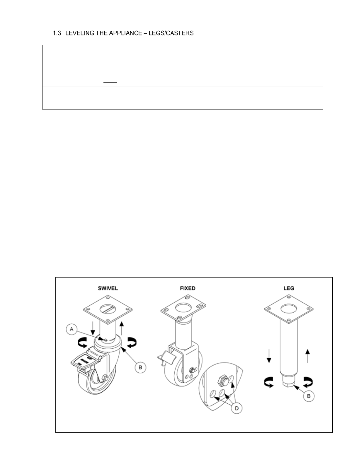
1. Swivel casters- loosen 2 set screws (A)
2. Legs and swivel casters-. Adjust the height of the leg / caster by turning adjustment collar/ foot (B)
with water pump pliers until desired change in height is achieved.
Swivel casters only: Retighten set screws (A).
3. Fixed casters- Adjust hei gh t by moving wheel and axle to alternate holes (D) in wheel bracket
higher or lower as needed. Refer to “FIXED” type caster in Figure 3.
4 Adjust remaining casters or legs as needed to ensure the appliance is supported evenly at each
caster/leg contact point.
L20-418 Rev 2 (5/16) 7
Figure 3 Caster and leg types
Page 8
PITCO VF SERIES INSTALLATION & OPERATIONAL MANUAL
A T, BG, CH, CZ, DK, EE, FI, GB, GR, HU, IE, IT, LT, LV, NO,
PL, PT, RO, ES, SI, SK, SE, TR
I
2H
LU
I
2E
FR
I
2ES I
2.2 mm / 2. 38 m m
BE
I
2E+
2.2 mm NO
DE
I
2EL L
2.2 mm / 2. 38 m m
NL
G25-G25.3 I
2L
- I
2EK
25 2.38 mm 2.3/2.2
BE, BG, CH, CZ, DE, ES, FR, GB, GR, HU, HR, IE, IS, IT, LT,
LU, LV, MK, MT, NL, PL, PT, RO, SI,
LP G31
I
3P
37/50 37 #54 0.8
A T, BG, CY, CH, CZ, DK, EE, FI, FR, DE, GR, HU, IE, IT, LT,
LU, MT, NL, NO, PL, RO, SI, SE, SK, TR
BU G30
I
3B/P
30/50 25.4 #55 0.6
A T, BG, CH, CZ, DK, EE, FI, GB, GR, HU, IE, IT, LT, LV, NO,
PL, PT, RO, ES, SI, SK, SE, TR
I
2H
LU
I
2E
FR
I
2ES I
2.2 mm / 2. 38 m m
BE
I
2E+
2.2 mm NO
DE
I
2EL L
2.2 mm / 2. 38 m m
NL
G25-G25.3 I
2L
- I
2EK
25 2.38 mm 2.9
BE, BG, CH, CZ, DE, ES, FR, GB, GR, HU, HR, IE, IS, IT, LT,
LU, LV, MK, MT, NL, PL, PT, RO, SI,
LP G31
I
3P
37/50 25.4 #54 1.0
A T, BG, CY, CH, CZ, DK, EE, FI, FR, DE, GR, HU, IE, IT, LT,
LU, MT, NL, NO, PL, RO, SI, SE, SK, TR
BU G30
I
3B/P
30/50 25.4 #55 0.8
VF655
VF35
19.0
LP16
LP16
Nat
G20/G25
G20/G25
G20
G20
20.5
26.5
24.5
10.8
18.5
20/25
20/25
20
20
10
Applicable
Countries
Nat
Nominal Gas
Rate (m3/hr)
Model
Fuel Type
Net
Input ( kW )
Supply
Pressure (mbar)
Burner
Pressure (mbar)
Governor
Gas
Appliance
Category
Gross
Input ( kW )
YES
N22
Burner
Orifice
Pilot
Orif i ce ( code)
2.5/2.9
2.0/2.3
2.0
2.5
2.2 mm
2.2 mm
N22
YES
YES
YES
Model
Fuel Type
Gross
Input
BTUs (kW)
Net Input
kW
Supply
Pressure
(mbar)
Burner
Pressure
(mbar)
Burner
Orifice
Pilot
Orifice
(code)
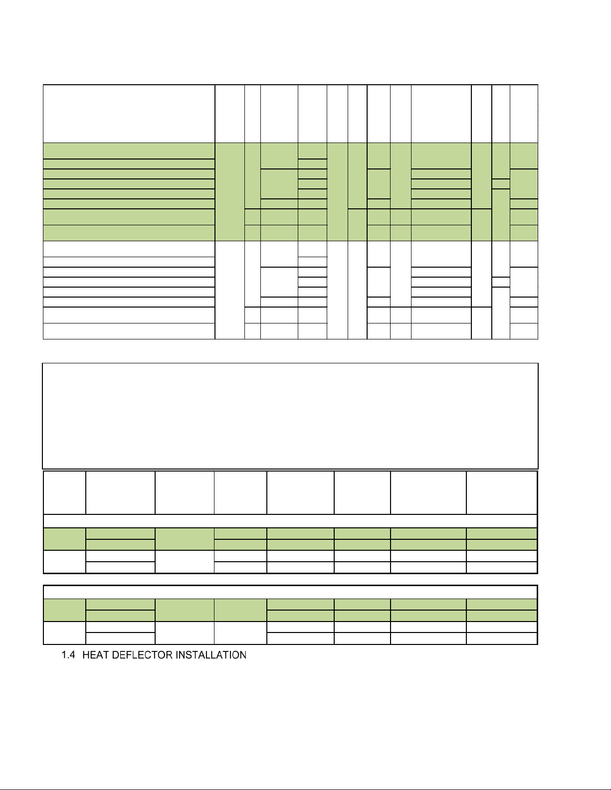
Natural 18 7" W. C. (17. 4) 4" W. C. (10) 2.2 m m N22
Propane 19 11" W. C. (27. 4) 10 W.C. (25) #54 LP16
Natural 25 7" W.C. (17.4) 4" W. C. (10) #43 N22
Propane 26 11" W. C. (27. 4) 10 W.C. (25) 1.45 LP16
Natural 1.74 k Pa 1.0 k Pa 2.2 m m 0. 56 m m (N22)
ULPG 2.74 k Pa 2.5 k Pa 1.40 m m (#54) 0.41 m m (LP 16)
Natural 1.74 k Pa 1.0 k Pa 2.2 m m 0. 56 m m (N22)
ULPG 2.74 k Pa 2.5 k Pa 1.40 m m (#54) 0.41 m m (LP 16)
NON-CE GAS TA BLE
VF35
VF65
95 Mj/ h
VF35
70,000 (20. 5)
95,000 (27. 8)
VF65
74 Mj/ h
67 Mj/ h
86 Mj/ h
AUSTRALIAN GAS TABLE
the Netherlands Only - Natural Gas
CE GAS TABLE
Refer to the following table for gas specifications for the country of use. If the country of use is NOT listed, refer
to the information printed on the data plate.
Belgium – Natural gas units require a restrictor orifice on the supply line for proper operation.
Dit toestel is afgesteld voor de toestelcategorie K (I2K) en is geschikt voor het gebruik van G en G+
distributiegassen volgens de specificaties zoals die zijn weergegeven in de NTA 8837:2012 Annex D met
een Wobbe-index van 43,46 – 45,3 MJ/m3 (droog, 0 °C, bovenwaarde) of 41,23 – 42,98 (droog, 15 °C ,
bovenwaarde). Dit toestel kan daarnaast worden omgebouwd en/of opnieuw worden afgeregeld voor de
toestelcategorie E (I
) Dit houdt derhalve in dat het toestel: “geschikt is voor G+-gas en H-gas, dan wel
2E
aantoonbaar geschikt is voor G+-gas en aantoonbaar geschikt is te maken voor H-gas” in de zin van het
“Besluit van 10 mei 2016 tot wijziging van het Besluit gastoestellen….”
If the appliance requires a heat deflector, you will find a removable label at the rear top edge of the unit. This
label has instructions for pos itionin g and ins ta llati on of the h eat def lector . Refer to the label and the
instructions below to install the deflector.
1. Remove the two self-drilling screws from the top, back area of the appliance.
2. Position the heat deflector so that the angled portion of the deflector is facing toward the front of
8 L20-418 Rev 2 (5/16)
appliance. Secure the heat deflector to the back of the unit using the two previously rem oved
fasteners.
Page 9

PITCO VF SERIES INSTALLATION & OPERATIONAL MANUAL
WARNING
dealer you purchased it from.
NOTICE
3. When properly installed the angled section of the heat deflector will extend over the flue opening to
redirect the heat. It SHOULD NOT cover the flue opening. Never allow anything to block the flue
opening; this will cause the appliance to overheat and inhibit prop er com bus tion, whic h could pr od uc e
dangerous gases
GAS CONNE CTION
Your gas appliance will give you peak performance when the gas supply line is of sufficient size to provide
the correct gas pressure. The gas line must be installed to meet the local building codes or North America
National Fuel Gas Code ANSI Z223.1 Latest Edition. In Canada, install the appliance in accordance with
CAN/CGA-B149.1 or .2 and local codes. In Australia, install the appliance in accordance with AS/NZS 5601
Latest Edition. Gas line sizing requirements can be determined by your local gas company or, in North
America, by referring to the National Fuel Gas Code, Appendix C, Table C-4 (for natural gas) and Table C16 (for propane). The gas line needs to be large enough to supply the necessary amount of fuel to all
appliances without losing pressure to any appliance.
A properly sized and installed gas line will deliver a supply pressure between 7.0” W.C.
(17.4mbars, 1.74kPa) and 10.0” W.C. (24.9mbars, 2.49kPa) natural gas or between 11.0” W.C.
(27.4mbars, 2.74kPa) and 13.0” W.C. (32.4mbars, 3.25kPa) for propane to all appliances
connected to the supply line, operating simultaneously at full demand.
THE PRESSURE AT THE GAS CONTROL VALVE SHALL NOT EXCEED ½ PSI (13.84 “WC, 34.5 mbar,
3.45 kPa).
The gas supply connection to this appliance is located in the rear of the appliance approximately 10-1/2”
(26.7 cm) from the floor of the appliance when legs are used.
Each appliance is equipped to operate on one certain fuel type. The type of fuel with which the
appliance is intended to operate is printed on the data plate, which is attached to the inside of the door.
NEVER supply the appliance with a gas other than the one that is indicated on the data
plate. Using the incorrect gas type will cause improper operation and could result in seriou s
injury or death. If you need to convert the appliance to another type of fuel, contact the
NEVER use an adapter to make a smaller gas supply line fit the appliance connection. This
may not allow proper gas flow for optimum burner operation, resulting in poor performance
and improper operation.
In North America, gas appliances equipped with casters must be installed with connectors that comply with
the Standard for Connectors for Movable Gas Appliances, ANSI Z21.69.CSA 6.16 Latest Edition. This
connection should include a quick disconnect device that complies with the Standard for Quick Disconnect
Devices for Use with Gas Fuel Appliances ANSI Z21.41.CSA 6.9 Latest Edition. In Australia, an appliance
equipped with casters and a flexible gas line must be connected to the gas supply with a quick disconnect
device that complies with AS 4627 Latest Edit ion and a restraining cable. The restraining cable must not
exceed 80% of the length of the flexible gas line. The restraining device should be attached to the appliance
at the back panel.
For Australia, the appliance must be installed in accordance with AS/NZS 5601 Latest Edition, local
authority and any other relevant statutory regulations. Flexible hose (if used) must comply with AS/NZS
1869 Class B or D, be of appropriate internal diameter, be kept as short as possible (not exceed 1.2
meters), must not be kinked and not be in contact with a hot surface. A chain must be fitted to restrict the
appliance movement to no more than 80% of the hose length.
The fuel supply system must be tested before the appliance is used. If the fuel line is going to be tested at a
pressure greater than ½ PISG (3.45 kPa, 34.5 mbar), ensure that that appliance is disconnected from the
fuel line. If the fuel line is to be tested at a pressure equal to or less than ½ PSIG (3.45 kPa, 34.5 mbar), the
L20-418 Rev 2 (5/16) 9
Page 10

PITCO VF SERIES INSTALLATION & OPERATIONAL MANUAL
WARNING
WARNING
WARNING
adequately protected.
appliance can be connected during the test, but the unit’s gas control valve must be turned OFF. Test all
gas line connections for leaks with a solution of soap and water when pressure applied.
The installation of this appliance MUST conform to local codes. In the absence of local codes in North
America, the installation must conform with the National Fuel Gas Code, ANSI Z223.1/NFPA 54 Latest
Edition or the Natural Gas and Propane Installation Code CSA B149.1 Latest Edition as applicable. In
Australia, the appliance must be installed in compliance with AS/NZS 5601 Latest Edition
Your new appliance must have proper ventilation to function safely and properly. Exhaust gas temperatures
can reach as high as 1100 °F (593 °C). Therefore, it is very important to install a fire safety system. Your
ventilation system should be designed to allow for easy cleaning. Frequent cleaning and proper
maintenance of the ventilation system and the appliance will reduce the chances of fire. Ventilation and fire
safety systems must comply to local and national codes for US and Canada. Refer to ANSI 83.11 for a list
of reference documents that will provide guidance on ventilation and fire safety systems. For installations in
U.S. and Canada, additional information can be obtained from CSA International, 8501 East Pleasant Valley
Road, Cleveland, OH, 44131 or visit their website at www.csa-international.org
system must comply with AS/NZS 5601.0.
It is essential that the appliance be operated only when adequate ventilation is provided. Your ventilation
hood should be properly maintained. A qualified installation professional should ensure that the hood is
operating properly in conjunction with the appliance. Inadequate ventilation may not properl y evacuate all
appliance emissions. Excessive or unbalanced ventilation may cause drafts, which could interfere with
proper operation of the pilot and burners. Leave at least 18 inches (47 cm) of open space between the flue of
the appliance and the intake of the exhaust hood.
. In Australia, the ven ti lation
Ensure that your ventilation system does not cause a down draft at the appliance’s flue opening. A
down draft will not allow the appliance to exhaust properly and will cause overheating, which may
cause permanent damage. Damage caused by down drafts will not be covered by the warranty.
NEVER allow anything to obstruct the flow of combustibles or ventilation exiting the appliance.
NEVER place anything on top of the flue area, or block the flue in any way. Never place a grease
condensing drip pan over the flue opening.
NEVER connect the ventilation blower or hood directly to the flue of this appliance. The resulting
increased flow of air through the combustion system will cause improper operation, poor
temperature recovery, poor ignition and could extinguish the pilot.
Replacing or adding appliances under a pre-existing fire safety system may require modifications to
the system. ALWAYS contact a professional who is qualified in installing, designing and main taining
your fire safety system to assure that any appliance located under the fire safety system are
10 L20-418 Rev 2 (5/16)
Page 11

PITCO VF SERIES INSTALLATION & OPERATIONAL MANUAL
WARNING
Before you begin filling and adjusting the appliance, perform the following visual c hec ks :
After the appliance is in its permanent location, check the levelness. Any additional leveling that is
necessary can be performed as previously described.
Ensure that the sensing probe and high temperature limit bulb are in place and secure. Check the
high limit bulb mounting screws to ensure that they are tight.
Review the installation portion of this manual and ensure that all steps have been followed and
executed properly.
1) Probe
2) High Temperature Limit
After your appliance has been properly installed as described in the INSTALLATION section of this manual,
it will need to be adjusted to ensure that it will perform as designed. A qualified person must perform these
adjustments.
To perform these adjustments the followi ng too ls will be needed:
Manometer
Digital Thermometer (Temperature Probe)
DC Voltmeter (capable of reading millivolts)
FILLING THE APPLIANCE
Refer to the following procedure to fill the cook tank prior to making adjustments.
1. Ensure that the drain valve is closed.
2. Fill the tank with WATER. Water is used for the installation adjustments because the
temperature will never exceed 212°F (100°C), thereby allowing plenty of adjustment time.
Never let the water level go below the MIN LEVEL mark stamped on the tank.
Oil/shortening must completely cover the heat tubes at all times while th e appliance is ON.
CAUTION
This appliance is not designed for cooking with water. Fill with oil/shortening only for cooking.
L20-418 Rev 2 (5/16) 11
Page 12

PITCO VF SERIES INSTALLATION & OPERATIONAL MANUAL
WARNING
set nearby materials on fire. Keep the area arou n d th e appliance free from combustibles.
WARNING
gas to dissipate.
PILOT
WARNING
ON
Thermostat Control Knob
Gas Control Valve Knobs
During operation, there is an open flame in side this appliance. The unit may get hot enough to
If pilot extinguishes, wait 5 minutes before attempting to relight the pilot to allow any built-up
LIGHTING INSTRUCTIONS
Refer to the following instructions to light the appliance.
1. Verify that all clearanc es , g as connect ions , ve nti latio n r equirements and
gas pressures have been properly implemented, tested, adjusted and
checked for compliance in accordance with the instruc tions and
requirements in the INSTALLATION section of this document prior to
proceeding.
2. Open the gas supply valves to the appliance.
3. Turn the thermostat control knob counterclockwise to the OFF
position.
4. Turn the gas control valve knob to the PILOT position and push in on the knob.
Hold the knob in for approximately one minute to purge the air out of the line.
5. While keeping the knob on the gas control valve depressed, hold a flame to the
pilot until the pilot ignites.
6. Keep the knob on the gas control valve pressed for approximately 30 seconds
or until the pilot remains lit without the knob being pressed.
7. If the pilot goes out, wait 5 minutes and repeat step 4. If after three tries the
pilot will not remain lit, refer to the TROUBLESHOOTING section of this
manual.
8. Once a pilot flame has been established, turn the gas control valve knob
counterclockwise to the ON position.
9. Set the thermostat control knob to the desired temperature setting, the burners
will ignite and be controlled by the thermostat.
Do not store flammable materials in or near this appliance. Do not spray aerosols in the vicinity
of this appliance while it is in operation. Contact a qualified service person or the factory,
using the information on the back of this manual, if the appliance produces unusual odor,
yellow tipping flames or is not performing as per the original installation.
12 L20-418 Rev 2 (5/16)
Page 13

PILOT FLAME ADJUSTMENT
Gas Control Valve / Millivolt
Gas Control Valve / Millivolt
Perform this procedure with the pilot lit.
Note: This procedure requires a DC millivolt meter set to a scale of 0-1000 mV. Using test leads
with sharp probes will help in taking the required readings. Using test leads with sharp probes
will help in taking the required readings
1. Locate the thermopile wires coming from the pilot to the
gas control valve.
2. Connect the positive (+) test probe to the terminal with the
red wire. Then connect the negative (-) test probe to the
terminal with th e wh ite wire.
3. Adjust the current reading to the required level by
adjusting the pilot flame. Remove the pilot adjustment cap
screw to expose the pilot adjustment screw. Turning the pilot
adjustment screw clockwise will decrease the size of the pilot
flame and flame sense current. Turning the pilot adjustment
screw counterclockwise will increase the pilot flame size and
the flame sense current.
4. Turn the screw in or out as needed to achieve a reading
of 550 mV ± 50 mV.
Note: Allow 3 to 5 minutes between flame adjustments to
allow the reading to stabilize.
Once the pilot flame has been adjusted properly, remove
the millivolt meter and replace the pilot adjustment cap
screw.
BURNER SYSTEM ADJUSTMENT
For the burners to operate the gas control valve must be open and
the thermostat must be turned ON. The burners receive gas from
the main gas supply through the thermostatically controlled gas
control valve. When the oil temperature drops below the preset
temperature the gas control valve opens.
The burners must be adjusted to deliver optimum flame. Refer to the following procedure to adjust the
burners.
1. Ensure that the gas control valve is shut OFF, remove the burner
2. Turn on this and all appliances connected to the gas supp l y line and
3. The installed pressure gauge should be the same, ±0.1” W.C.
4. Turn off ALL appliances, turn OFF the gas control valve on your Pitco appliance and remove the
5. Check for leaks at the burner pressure tap.
PITCO VF SERIES INSTALLATION & OPERATIONAL MANUAL
1. Pressure Regulator Cap
Screw
2. Pilot Adjustment Cap Screw
1. Pressure Regulator Cap
Screw
2. Pilot Adjustment Cap Screw
pressure tap plug and connect an accurate pressure gauge (range of
0-16 “W.C. (39.85mbar, 3.98kPa) in 0.1” (.25mbar, .02kPa)
increments) or manometer.
light their burners. The pressure reading of the installed pressure
gauge should not drop from the required installation pressure. Any
loss of pressure indicates inadequate supply line installation, which
will cause poor performance of all appliances during peak usage.
(.25mbar, .02kPa), as that marked on the data plate on the inside
door of the appliance. If the pressure is correct, go to step 6, if it is
not, adjust the pressure as outlined in step 4. To adjust the pressure,
remove the pressure regulator cap screw and, with a flat head
screwdriver, adjust the regulator screw until the proper burner
pressure is reached. Turning the screw clockwise will increase the
Burner Pressure Tap
burner pressure. Turning the screw counterclockwise will decrease
the burner pressure. When the pressure is correct, replace the pressure regulator cap screw.
IF the pressure cannot be set to within these limits of the pressure stated on the data plate,
DO NOT operate the appliance. Contact an Authorized Service Company.
pressure gauge. Apply pipe joint compound to the burner pressure tap plug and reinstall it.
L20-418 Rev 2 (5/16) 13
Page 14

PITCO VF SERIES INSTALLATION & OPERATIONAL MANUAL
CAUTION
operation and cleaning of this appliance.
CAUTION
WARNING
means of securing the appliance in place are not used.
WARNING
Opening the drain valve will lead to the outflow of the hot contents of the appliance.
NOTICE
butcheries, etc., but not for continuous mass production of food.
WARNING
disposing of water. The water is extremely hot and can cause severe injuries.
CAUTION
the heat tubes.
WARNING
Be careful not to disturb the probe and high temperature limit bulb and capillary during
When your appliance is shipped, many of its parts are covered with a thin coat of oil for protection. Before
the appliance is ready for cooking all transit materials must be removed and the appliance must be cleaned.
This will remove the oil coating and any foreign matter that may have accumulated during storage and
shipment. Refer to the following procedure to clean the appliance.
Wear protective gloves and clothing when clea ning and draining the appliance and when
DO NOT leave the appliance unattended during cleaning. Never let the liquid level go below
1. Read the OPERATION section of this manual prior to filling or operating the appliance.
2. The following steps should be followed using a food grade cleaner.
Use a commercial grade cleaner formulated to effectively clean and sanitize food contact
surfaces. Read the directions and precautionary statements before use. Particular attention
must be paid to the concentration of cleaner and the length of time the cleaner remains on the
food contact surfaces.
3. Following the cleaning directions in this manual to clean the tank interior and all other food contact
surfaces. (6.3.1 Boil Out Procedure, page 20)
4. When cleaning is complete, rinse the inside of the tank thoroughly with cool water. Continue to rinse
the tank until the cleaner has been completely and thoroughly rinsed from the tank.
5. Using a clean dry cloth, wipe out all of the water in the fry tank.
If the appliance can’t be adjusted to operate properly contact a qualified service per son or
contact the factory using the contact information on the back of this manual.
Before operating the appliance, check that tipping restraints or other features to prevent
tipping are installed and mechanically s o u nd . Splashing of hot liquid may occur if adequate
This appliance is intended to be used for commercial applications, for example in the kitchens
of restaurants, canteens, hospitals and in commercial enterprises such as bakeries,
14 L20-418 Rev 2 (5/16)
Page 15

PITCO VF SERIES INSTALLATION & OPERATIONAL MANUAL
Lbs.
kg
liter
VF35
35
15.9
17.5
VF65
65
29.5
32.4
CAUTION
OPERATION
Both liquid and solid oil/shortening can be used in this appliance, but liquid is preferred. If solid
oil/shortening is used it is recommended that you melt the oil/shortening before adding it to the appliance.
You can melt solid oil/shortening in the appliance, but you must be very careful not to scorch the
oil/shortening.
This appliance is NOT designed for cooking with water. Cook with oil or shortening only.
To fill the tank with liquid shortening, refer to the following procedure.
OIL CAPACITIES
APPLIANCE
MODEL
It is recommended that high quality liquid frying oils be used for longest oil life.
1. Verify that the tank interior is clean and free of any construction debris and moisture.
2. Rinse the tank and drain line with a small amount of clean cooking oil.
3. Ensure that the drain valve is closed.
4. Fill the tank to about the MIN oil level mark. The oil will expand when heated up, raising the level to
OIL LEVEL line.
5. After the cooking oil is at operating temperature, add oil to the frypots as needed to obtain the desired
operating level.
Illustration of liquid oil/shortening fill.
TANK
OIL CAPACITY*
L20-418 Rev 2 (5/16) 15
Page 16

PITCO VF SERIES INSTALLATION & OPERATIONAL MANUAL
WARNING
WARNING
WARNING
CAUTION
To fill the tank with solid oil/shortening refer to the following procedure
1. Remove the screen covering the heat tubes (tube screen).
2. Cut the solid oil/shortening into cubes no larger than one inch (2.54 cm). ALWAYS pack the
oil/shortening below, between, and on top of the heat tubes.
DO NOT leave any large air gaps. Use care when packing the solid oil/shortening into the
tank.
DO NOT bend or break the temperature or high limit sensor probes. If these are damaged
the appliance will not function pro perly.
3. Once the appliance tank is firmly packed with solid oil/shortening, the oil/shortening must be
melted. Melt the oil/shortening by cycling the burners ON for 4 seconds and OFF for 30 seconds
repeatedly, using the thermostat knob.
AVOID these conditions.
Very Hazardous Excessive and large spaces
16 L20-418 Rev 2 (5/16)
NEVER melt blocks of solid shortening on top of the heat tubes. This can cause a fire and
could result in personal injury
Oil must completely cover the heat tubes at all times while appliance is on.
Do not overload the fry baskets, or allow the oil level to exceed the MAX line while cooking.
Wet product, or too much oil in the frypot can lead to surge boiling, and over topping the
frypot. Overtopping may create hazards such as burns or slippery floors.
This appliance is NOT designed for cooking with water. Severe appliance damage will occur if
a fryer is used as a water bath for rethermalizi n g foods. Damage of this type is not covered
under the warranty.
Page 17

PITCO VF SERIES INSTALLATION & OPERATIONAL MANUAL
Maximum Allowable Load per Tank Size (W x L)
7 x 14 in
(17.8 x 35.6 cm)
14 x 14 in
(35.6 x 35.6 cm)
18 x 18 in
(45.7 x 45.7 cm)
14 x 18 in
(35.6 x 45.7 cm)
18 x 14 in
(45.7 x 35.6 cm)
Typical French Fry Cook Times (m/s)
Temperature
350°F
360°F
370°F
Fry Thickness
(177°C)
(182°C)
(188°C)
Thin
2:45
2:30
2:15
Medium
3:45
3:30
3:15
Thick
4:15
4:00
3:45
determine exact cook temperatures and times.
WARNING
WARNING
WARNING
WARNING
APPLIANCE START UP
Refer to the following procedure to start the appliance prior to operation.
1. Fill the cook tank with oil/shortening (See Section 2.1 FILLING THE COOK TANK). Never operate the
appliance unless the cook tank is properly filled.
2. Light the pilot as previously described in this manual.
3. Turn the temperature control knob (thermostat) to the desired temperature setting. This knob is
located behind the door.
4. The appliance is now on and heating the oil/shortening in the cook tank.
NEVER operate the appliance with an empty fry tank. It will void the warranty.
Oil/shortening level should NOT be allowed to fall below the indicated level line at any time. Dry
firing of the fry tank will shorten tank service life and will void your warranty.
Oil level should NOT be allowed to fall below the indicated level line at any time. Dry fir ing of the
tank may cause a fire, and can shorten tank service life. Evidence of dry firing will void your
warranty.
To ensure the quality of the food you cook in this appliance, follow the preparation instructions from the food
manufacturer. When the appliance is not in use, the oil should be cooled and covered to prevent
contamination.
1.5 lbs. (0.68kg) 3 lbs. (1.36 kg) 5 lbs. (2.27 kg) 3 lbs. (1.36 kg) 5 lbs. (2.27 kg)
Always follow the food manufacturer’s directions.
The lower the oil temperature, the longer the
cooking time and the greater the fat absorption.
NEVER ov er fill appliance baskets. Overfilling
can result in soggy, greasy product.
When removing baskets from the cook tank,
shake gently to remove excess oil.
Never leave a basket over the appliance. The
heat from the cook tank will continue to cook the
product.
Oil/shortening quality can affect product quality.
Keep salt and water away from the oil/shortening
to maintain its life. Oil/shortening filtration
removes crumbs from the oil which will also
extend its life.
This table is for reference only. Please refer to
the product manufacturer’s specifications to
Dry fired heat tubes are extremely hot, will shorten the tank service life and will void your warranty.
L20-418 Rev 2 (5/16) 17
Page 18

PITCO VF SERIES INSTALLATION & OPERATIONAL MANUAL
OIL TEMPERATURE
you money and increase the fire danger.
TEMPERATURA DELL’OLIO
temperature non prevedono vantaggi, sono antieconomiche e aumentano il rischio d’incendio.
ΘΕΡΜΟΚΡΑΣΙΑ ΛΑΔΙΟΥ
χρήματα και αυξάνουν τον κίνδυνο πυρκαγιάς.
WARNING
apron, heat resistant gloves for ski n p rotection and goggles for eye protection.
Keep the oil temperature in the fryer to a maximum of 190°C (374°F). Higher temperatures will cause rapid
breakdown of the oil and give you no faster cooking. At 205°C (401°F) to 210°C (410°F) the life of the oil is
only one third of its life at 190°C (374°F). In addition, increased decomposition causes the oil to smoke badly
even if the temperature is lowered to 190°C (374°F) again. High temperatures give you no advantage, cost
Mantenere la temperatura dell’olio nella friggitrice fino a un massimo di 190°C. Temperature maggiori
causano un rapido degrado dell’olio, senza tuttavia eseguire una cottura più rapida. Da 205°C a 210°C la
durata dell’olio è inferiore di un terzo rispetto a quella a 190°C. Inoltre, l’accresciuta decomposizione
comporta una forte emissione di fumo, anche se la temperatura viene riportata di nuovo a 190°C. Le alte
Διατηρείτε τη θερμοκρασία λαδιού στη φριτέζα μέχρι 190 βαθμούς Κελσίου. Υψηλότερες θερμοκρασίες θα
αλλάξουν τη σύνθεση του λαδιού πολύ σύντομα και δεν ψήνετε γρηγορότερα. Η δυναμικότητα του λαδιού
στους 205-210 βαθμούς Κελσίου είναι μόνο το ένα τρίτο της δυναμικότητάς του στους 190 βαθμούς
Κελσίου. Επιπλέον η αυξημένη αποσύνθεση του λαδιού, σε θερμοκρασίες πάνω από 190 βαθμούς Κελσίου,
κάνει το λάδι να καπνίζει άσχημα κι αν ακόμη κατεβάσετε τη θερμοκρασία κατόπιν πάλι στους 190 βαθμούς
Κελσίου. Οι υψηλές θερμοκρασίες δε σας παρέχουν κανένα πλεονέκτημα, σας κοστίζει περισσότερα
APPLIANCE SHUTDOWN
There are two shutdown modes of appliance operation: STANDBY and COMPLETE. The standby mode
removes the ability of the appliances burners to operate. COMPLETE shutdown turns off the gas supply to
the appliance. A STANDBY shutdown can be used during slow business periods. ALWAYS perform a
COMPLETE shut down when the appliance will not be in use and unsupervised for an extended period of
time. Refer to the following procedures to enter the appropriate shutdown mode.
1. Turn the thermostat to the OFF position. Turn the Pilot knob clockwise to the PILOT position.
The cooker is now in Standby and can remain this way for only brief periods of time. NEVER
leave the appliance in standby mode for prolonged periods or overnight.
1. Turn the thermostat knob to the OFF position.
2. Depress and turn the Pilot knob counter clock-wise to the OFF position.
3. The appliance is now completely shut down and can be cleaned and filtered if desired.
PREVENTATIVE MAINTENANCE
Performing the preventative maintenance steps below daily will keep your appliance safe and at peak
performance. During the cooking process, oil/shortening may spill and splatter and requires immediate
attention. Furthermore, during the cooking process, particles, crumbs and crackling collect inside the fry
tank reducing product quality and decreasing oil/shortening life. If you are producing high quantities of fried
food and/or frying heavily battered food, it will be necessary to perform these steps more than once a day.
Serious injury could result from direct contact with hot surfaces and/or oil. Always wear
18 L20-418 Rev 2 (5/16)
Page 19

PITCO VF SERIES INSTALLATION & OPERATIONAL MANUAL
WARNING
wear apron, heat resistant gloves for skin protection and goggles for eye protection
WARNING
WARNING
DAILY CLEANING
At least daily, filtering the oil is required. Make sure a clean filter is used every day.
Using the cleaning brush, crumb scoop and clean out rod, remove all the loose debris
APPLIANCE INSPECTION
Check that the high temperature limit and temperature probe are in the correct position and secured
in place. (Refer to illustration on page 11 of this manual).
Check around the appliance for loose parts or accessories that need to be secured or other foreign
items (ex: Aerosol cans) that should be removed from the area.
Check for oil/shortening leaks around the inside and o utside of the cabinet and around the
appliance.
Serious injury could result from direct contact with hot surfaces and/or oil. Always
Read the OPERATION section of this manual prior to filling or operating the appliance.
DO NOT leave the appliance unattended during cleaning.
CLEANING THE COOK TANK
Recommended at least once a week.
1. Follow the procedure from 4.2. (COMPLETE SHUTDOWN) turn OFF and drain the oil/shortening.
Allow the unit to cool, then perform the following procedure for cleaning.
2. Remove baskets, tank rack and basket hanger for cleaning in pot sink, power soak sink or
dishwasher.
3. Using the cleaning brush, crumb scoop and clean out rod, remove all the loose debris and scrub
all tank surfaces.
4. For tougher carbonized oil/shortening and carbon buildup scrub tank using a Scotchbrite or other
abrasive pad. DO NOT use steel wool.
5. Wipe residue with a clean water dampened cloth. Carefully dry and REMOVE ALL MOISTURE
from the tank before returning oil/shortening into the tank.
6. Clean and dry baskets, tank rack and basket hanger before reinstalling.
7. Refill tank with oil/shortening.
CLEANING THE CABINET
1. Wipe any spilled oil/shortening, dust and lint from the cabinet exterior with a clean damp cloth and
a mild food grade detergent. Be careful not to get any water or detergent in the oil/shortening. Use
a nonabrasive pad for tougher stains if needed.
2. Remove detergent from all surfaces.
3. Cleaning the interior cabinet requires a clean cloth to remove any oil/shortening, dust, lint or filter
powder (i.e.: Magnesol) from the interior of the cabinet.
L20-418 Rev 2 (5/16) 19
Page 20

PITCO VF SERIES INSTALLATION & OPERATIONAL MANUAL
Performing the preventative maintenance steps above on a daily basis will keep your appliance clean and
safe. On a weekly basis, these additional steps should be performed. Wear personal protective gear when
performing preventative maintenance!
1. Turn the appliance OFF. Allow the oil/shortening to cool to room temperature before pulling the
appliance away from the hood. Hint: This maintenance may be ideal to perform on the day the
oil/shortening is being changed so no oil/shortening is present in the tank.
2. Disconnect the gas hose and rete nti on la n yard.
3. Wearing your protective gear, pull the appliance away from the hood.
4. Check that vent hood drip cup is empty and not dripping oil/shortening into the flue.
5. Check that the hood baffles are clean and not dripping oil/shortening into the flue.
6. Clean the appliance sides, back and the flue area, it may be necessary to use a non-abrasive pad to
scour and a putty knife to scrape the oil/shortening buildup. With a clean damp cloth and food grade
detergent wipe the area clean.
7. Wipe up any excessive oil/shortening on the gas hose with a dry cloth.
8. Check flue pipe for any foreign debris/object and remove if found.
9. Reattach gas hose and retenti on lanyard then push appliance back under the hood.
Food debris and oil/shortening can build up inside the tank. Performing the monthly preventative
maintenance steps below will keep your appliance safe and at peak performance. If you are producing high
quantities of fried food and/or frying heavily battered food, it may be necessary to clean these components
more than once a month.
BOIL OUT PROCEDURE
Wear protective gloves and clothing when cleaning and draining the appliance. Oil/shortening, water or
steam may spatter and will cause injury to personnel.
1. Read the “OPERATION” section of this manual prior to filling or operating the appliance.
2. Turn the appliance OFF. Drain al l the oil/shortening from the tank into a container and allow it to
cool. The container must be large enough to hold the entire contents of the tank and must also be
able to withstand 400°F (205°C) temperatures.
3. To drain the tank, open the drain valve.
4. Remove baskets, tank rack and basket hanger for cleaning in pot sink, power soak sink or
dishwasher.
5. Remove and discard any large debris inside the tank.
6. Close the drain valve.
7. Fill the tank with water and set the thermostat for 200°F (93°C.)
8. Once the water reaches a simmer, follow the directions of the boil out product that you are using.
9. Scrub the inside of the tank using a cleaning brush safe for hot water. Care must be taken to
remove all the foreign material on the tank, heat tubes, sidewalls and other components in the tank.
Be careful not to loosen or damage the high limit or temperature probe during when scrubbing.
10. Drain the water from the tank into a container that is large enough to hold the contents of the tank
and is suitable for use with 212°F(100°C) water .
11. Once the tank has cooled, rinse it thoroughly with clean, potab le water.
12. Remove all remaining water and residue with a clean dry cloth.
13. Clean and dry baskets, tube rack and basket hanger before reinstalling
14. Close the drain valve and fill the cooker tank with oil/shortening. See Section 2.1. FILLING THE COOK
TANK.
20 L20-418 Rev 2 (5/16)
Page 21

PITCO VF SERIES INSTALLATION & OPERATIONAL MANUAL
This section should ONLY be performed by a qualified service technician as part of a regular kitchen
maintenance program. This inspection should take place a minimum of once a year by an Authorized
Service Technician recommended by Pitco. It may be necessary perform this inspection more than once a
year.
SAFETY EVALUATIO N
Check legs, casters, wheels, plate welds and ensure all nuts and bolts are secured.
Check conditions of flexible gas line and verify appliance retention / lanyard system is in place.
MECHANICAL INSPECTION
Check frypot for shortening leaks and excessive oil build up
Check for oil migration (Clean as required)
Check hood drain cup, ensure it is empty and not dripping into the flue.
Check hood baffle for clean surface, oil/water condensate can drip on and into the flue.
Check flue for foreign debris and hood down draft currents.
Check drain/filtration system (if equipped) for leaks
Check for missing appliance parts, i.e.: cover strips
Check for missing fasteners
TEMPERATURE CONTROL SYSTEM
Check temperature probes and limits for carbon build up and plating. Clean as required
Check proper mounting of probes and sensors and all fasteners are secure.
Check thermistor probe resistances for stability.
Check Controller/thermostat features to ensure they are functioning.
Check Temperature Calibration
GAS COMBUSTION SYSTEM
Check for gas leaks.
Check and clean vent tube on gas control valve pressure regulator.
Check burners, clean debris and grease from pilot and pilot orifice tips.
Check and adjust the burner pressure to nameplate reading.
Check incoming gas pressure to the appliance under static and dynamic conditions.
Check ignition system and adjust pilot flame as required.
Check flame sensor reading.
Check gap spacing and clean igniter.
Recheck for gas leaks after inspection.
L20-418 Rev 2 (5/16) 21
Page 22

PITCO VF SERIES INSTALLATION & OPERATIONAL MANUAL
CAUTION
defective. Turn OFF the gas control valve. Contact an Authorized Service Company.
Proper ventilation hood operation is very important for the correct operation of this appliance and the safety
of personnel. The ventilation hood should be inspected at the time of installation of this appliance to ensure
that it will operate properly in conjunction with the appliance. A regular schedule of examination in
accordance with ANSI/NFPA 96 latest edition and/or local codes must be followed.
This MUST be performed with oil/shortening in the tank.
1. Use a high-grade pyrometer or digital thermometer suitable for temperature up to 380°F (193°C).
Place the thermometer in the oil, above the tip of the appliance’s temperature probe and within 1”
(2.54 cm). Be sure not to touch the heat tubes since this will measure incorrect temperatures.
Allow several minutes for the thermometer to equalize with the oi l temper atur e.
2. Light the pilot as described in this manual, set the thermostat to 325°F (163 °C) and allow the
oil/shortening to come up to temperature. Watch the thermometer closely as the temperature
rises.
3. If the oil/shortening temperature reaches 350°F (177°C) and the burners do not turn off, turn the
thermostat down. Keep lowering the thermostat setting until the burners go out.
If the burners do not shut off at the LOWEST thermostat setting, the thermostat may be
4. Let the appliance cycle 4 to 6 times before checking the temperature. Compare the
thermometer temperature against the thermostat setting. If the values are more than 5°F
(3°C) apart, contact an Authorized Service Company for further assistance.
22 L20-418 Rev 2 (5/16)
Page 23

PITCO VF SERIES INSTALLATION & OPERATIONAL MANUAL
WARNING
TROUBLESHOOTING
This appliance is equipped with a high temperature limit switch. The high temperature limit switch will stop
the appliance from functioning if the oil temperature in the cook tank reaches an unsafe temperature. In the
event that the high temperature limit has tripped, please refer to the following procedure to reset the switch.
Turn the appliance OFF.
a. Allow the appliance ample time to cool to room temperature.
b. Add oil/shortening to the cook tank as needed.
c. Press the high temperature reset button.
d. The high limit switch is now reset and the appliance is ready for startup.
DO NOT add oil/shortening to the tank until it has been given ample time to cool down.
Failure to do so may result in damage to the appliance and/or injury to the operator.
L20-418 Rev 2 (5/16) 23
Page 24

PITCO VF SERIES INSTALLATION & OPERATIONAL MANUAL
NO
Is the gas control
“PILOT” position?
NO
Turn the gas control valve knob to the
"PILOT" position and light pilot.
Purge air from pilot line.
stay lit after
pilot knob is
YES
YES
NO
line?
YES
NO
Is high
open?
YES
Did high
reset?
YES
NO
NO
go out when
temperature
YES
NO
Purge air from pilot line by turning gas
Light pilot.
NO
Is the gas
control valve
position?
YES
Is the
position?
NO
YES
YES
Turn the gas control
"ON" positi on.
NO
Turn the thermostat
temperature setting.
YES
Fryer does not work.
Does pilot
released?
Does pilot
increases?
If the burners are lighting, but not
performing properly refer to the
INSTALLATION section of this
manual to verify proper installation.
Will the
pilot
light?
Do the
burners
light?
valve in the
Is all the air
purged from
the pilot gas
control valve knob to the "PILOT" position
and holding it in for approx. 1 minute.
knob in the
"ON"
valve knob to the
limit
switch
Contact a qualified
service technician.
thermostat
knob in the
OFF
knob to the required
With the gas control
valve knob in the
"PILOT" position, hold
the knob in for approx.
1 minute. Light pilot.
Light the pilot.
limit
switch
24 L20-418 Rev 2 (5/16)
Page 25

PITCO VF SERIES INSTALLATION & OPERATIONAL MANUAL
Model
Cooking Area
Length
Cooking Area
Width
Cooking Area Depth Overall Height Overall Wi dth Overall Depth
Shipping
Weight
VF35 14" (35.6 cm) 14" (35.6 c m )
2.0' - 3.5"
(5.1 - 8. 9 cm)
47.3" (120.1 cm ) 15.6" (39. 6 cm) 32" (81.3 c m ) 161 lbs. (73 kg)
VF65 18" (45.7 cm) 17.3" (44 c m )
4" - 6"
(10.2 - 15. 2 cm)
47.3" (120.1 cm )
19.6" (49.8 cm ) 34" (86.4 c m ) 181 lbs. (82 k g)
L20-418 Rev 2 (5/16) 25
Page 26

PITCO VF SERIES INSTALLATION & OPERATIONAL MANUAL
In the event of problems wi th or quest ions
In the event of problems wi th or quest ions
Annual service to this appliance by an authorized person is recommended. Do not modify this appliance:
servicing must only be carried out by an authorized person. For service and parts, minor adjustments, fault
finding, or if this appliance cannot be adjusted to operate correctly, contact:
about your order, please contac t the P it co
factory at
+1 (603) 225-6684 World Wide
Website Address: www.pit co.c om
MAILING ADDRESS – P.O. BOX 501, CONCORD, NH 03302-0501
SHIPPING ADDRESS – 39 SHEEP DAVIS RD., PEMBROKE, NH 03275
Original instructions.
about your appliance, please contact the Pitco
Authorized Service and Parts repr es entati ve
(ASAP) covering your area, or con tact Pitco at
the numbers li s ted to the left.
26 L20-418 Rev 2 (5/16)
 Loading...