

Page 1
IMPORTANT FOR FUTURE REFERENCE
Please complete this information and retain this manual
for the life of the equipment:
Model #: ___________________________
Serial #: ___________________________
Date Purchased: ____________________
ENGLISH
Exploded Parts Manual
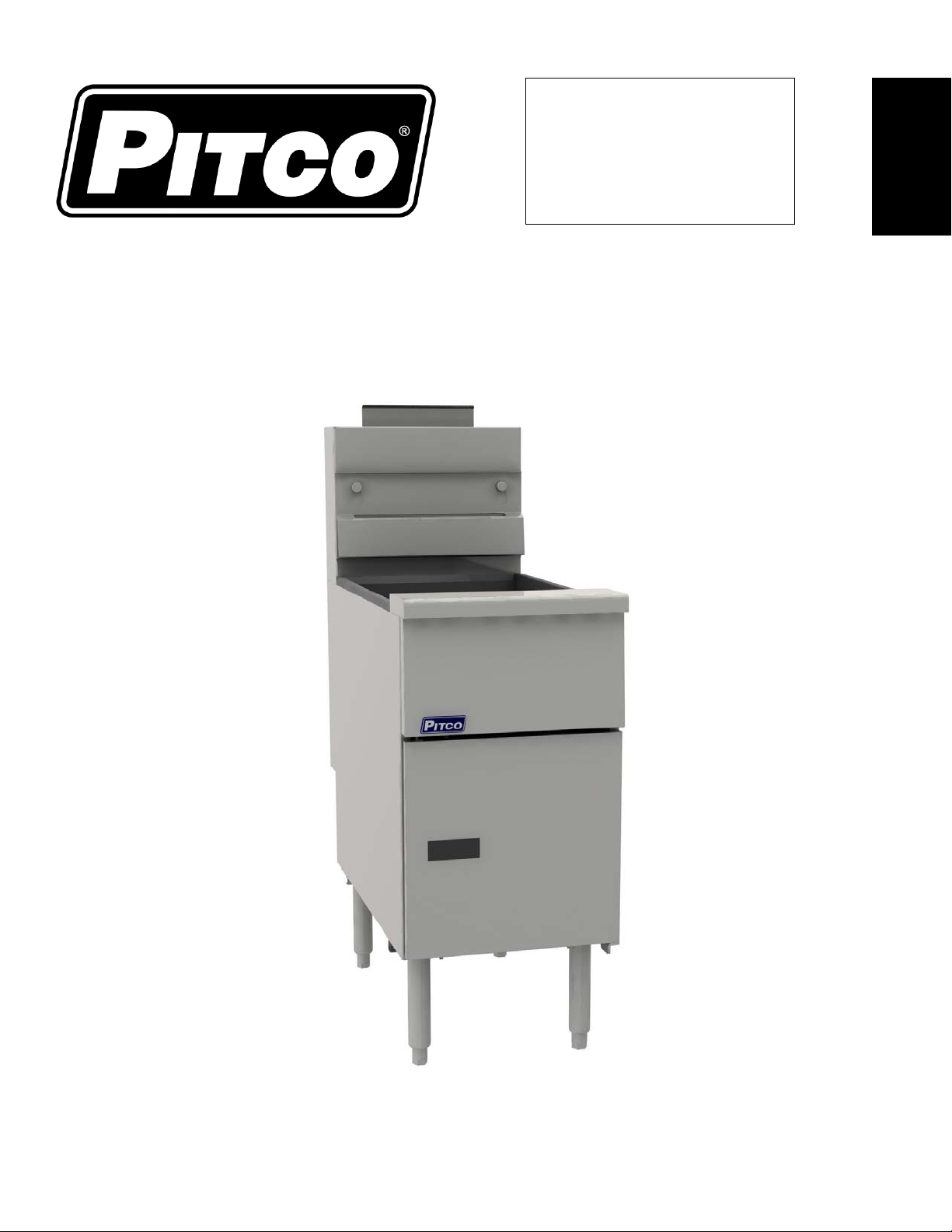
VF35 Gas Fryer Models
L22-382 Rev 1 (8/14)
Page 2

TO THE PURCHASER, OWNER AND
STORE MANAGER
Please review these warnings prior to
posting them in a prominent location for
reference
Post in a prominent location the instructions to be
followed in the event that an operator smells gas.
Obtain this information from your local gas supplier.
WARNING
DO NOT store or use gasoline or other flammable vapors and liquids
in the vicinity of this or any other appliance.
WARNING
Improper installation, alteration, service or maintenance can cause
property damage, injury or death. Read the installation, operating and
maintenance instructions thoroughly before installing or servicing this
appliance.
WARNING
Installation, maintenance and repairs should be performed by a Pitco
Authorized Service and Parts (ASAP) company technician or other
qualified personnel. Installation, maintenance or repairs by an
unauthorized and unqualified personnel will void the warranty.
WARNING
Installation and all connections must be made according to local codes
in force. In the absence of local codes in North America, the installation
must conform with the National Fuel Gas Code, ANSI Z223.1/NFPA 54 or
the Natural Gas and Propane Installation Code CSA B149.1 as
applicable. In Australia, the appliance must be installed in compliance
with AS/NZS 5601.
WARNING
During the warranty period if a customer elects to use a non-original part
or modifies an original part purchased from Pitco and/or its Authorized
Service and Parts (ASAP) companies, this warranty will be void. In
addition, Pitco and its affiliates will not be liable for any claims, damages
or expenses incurred by the customer which arises directly or indirectly,
in whole or in part, due to the installation of any modified part and/or
received from an unauthorized service center.
WARNING
This appliance, when installed, must be electrically grounded in
accordance with local codes, or in the absence of local codes, with the
National Electrical Code, ANSI/NFPA 70, or the Canadian Electrical Code,
CSA C22.2, as applicable
WARNING
Adequate means must be provided to LIMIT the movement or this
appliance without depending on the gas or electrical cord connection.
Single appliances equipped with legs must be stabilized by installing
anchor straps. All appliances equipped with casters must be stabilized by
installing restraining chains.
WARNING
DO NOT alter or remove structural material on the appliance to
accommodate placement under a ventilation hood.
WARNING
If the appliance is equipped with a power cord and it is damaged, it must
be replaced by a Pitco Authorized Service and Parts (ASAP) company
technician, or a similarly qualified person in order to avoid a hazard.
WARNING
The power supply must be disconnected before servicing, maintaining or
cleaning this appliance.
WARNING
The appliance is NOT jet stream approved. DO NOT clean the appliance
with a water jet.
WARNING
DO NOT attempt to move this appliance or transfer hot liquids from one
container to another when the unit is at operating temperature or filled
with hot liquids. Serious personal injury could result if skin comes in
contact with the hot surfaces or liquids.
WARNING
DO NOT use an open flame to check for gas leaks!
WARNING
DO NOT sit or stand on this appliance. The appliance’s front panel, tank,
splash back, tank cover, work shelf, drain board is not a step. Serious
injury could result from slipping, falling or contact with hot liquids.
Exploded Parts-VF35 Gas Model
WARNING
NEVER use the appliance as a step for cleaning or accessing the
ventilation hood. Serious injury could result from slips, trips or from
contacting hot liquids.
WARNING
The oil/shortening level should NOT fall below the minimum indicated level
line at any time. The use of old shortening can be dangerous as it will
have a reduced flash point and be more prone to surge boiling.
WARNING
The contents of the crumb catch and/or filter pan of any filter system must
be emptied into a fireproof container at the end of the frying operation
each day. Some food particles can spontaneously combust into flames if
left soaking in certain oil/shortening materials.
WARNING
Completely shut the appliance down when shortening/oil is being drained
from the appliance. This will prevent the appliance from heating up during
the draining and filling process. Serious injury can occur.
WARNING
This appliance is intended for indoor use only.
WARNING
DO NOT operate appliance unless all panels and access covers are
attached correctly.
WARNING
It is recommended that this appliance be inspected by a qualified service
technician for proper performance and operation on a yearly basis.
WARNING
There is an open flame inside this appliance. The unit may get hot enough
to set nearby materials on fire. Keep the area around the appliance free
from combustibles.
WARNING
DO NOT supply the appliance with a gas that is not indicated on the data
plate. If you need to convert the appliance to another type of fuel, contact
your dealer.
WARNING
If gas flow to appliance is interrupted, or pilots extinguish, wait 5 minutes
before attempting to relight the pilot to allow any residual gas in appliance
to dissipate.
WARNING
Ensure that the appliance can get enough air to keep the flame burning
correctly. If the flame is starved for air, it can give off a dangerous carbon
monoxide gas. Carbon monoxide is a clear odorless gas that can cause
suffocation.
WARNING
Never add oil to the appliance when it is at operating temperature.
Splashing hot oil can cause severe injuries.
WARNING
Never add water to hot oil. Violent boiling can occur causing severe
injury.
WARNING
This appliance is intended for professional use only and should be
operated by fully trained and qualified personnel.
WARNING
To avoid splashing of hot liquid when installed, this fryer must be
restrained either by the manner of installation, or with adequate ties to
prevent tipping.
WARNING
An appliance equipped with casters and a flexible gas line must be
connected to the gas supply with a quick disconnect device. In North
America, gas appliances equipped with casters must be installed with
connectors that comply with the Standard for Connectors for Movable Gas
Appliances, ANSI Z21.69.CSA 6.16 Latest Edition. This connection should
include a quick disconnect device that complie s w ith the Standard for Quick
Disconnect Devices for Use With Gas Fuel ANSI Z221.41.CSA 6.9 Latest
Edition. In Australia, an appliance equipped with casters and a flexible gas
line must be connected to the gas supply with a quick disconnect device that
complies with AS 4627. The hose must comply with AS/NZS 1869 and be
class B or D and have a restraining cable. The restraining cable must not
exceed 80% of the length of the flexible gas line.
L22-382 Rev 1 (08/14)
Page 3

Exploded Parts-VF35 Gas Model
NOTICE
In the event of problems or questions about your order, contact the Pitco Frialator factory at (603) 225-6684.
In the event of problems or questions about your equipment, contact the Pitco Frialator Authorized Service and Parts
representative (ASAP) covering your area, or contact Pitco at the number listed above.
Mailing Address
Pitco Frialator
P. O. Box 501
Concord, NH 03302-0501
Shipping Address
Pitco Frialator
10 Ferry Street
Concord, NH 03301
L22-382 Rev 1 (8/14)
3
Page 4

Exploded Parts-VF35 Gas Model
TABLE OF CONTENTS
A) FRYER EXPLODED VIEWS .......................................................................................................................... 5
FRYER EXPLODED PARTS LIST/VIEW ..................................................................................................................................... 5
B) TANK & FLUE ................................................................................................................................................ 6
TANK & FLUE EXPLODED PARTS LIST/VIEW ........................................................................................................................... 6
C) BURNER ASSEMBLY ................................................................................................................................... 7
BURNER ASSEMBLY EXPLODED PARTS LIST/VIEW .................................................................................................................. 7
D) GAS TRAIN.................................................................................................................................................... 8
GAS TRAIN DRAWING PARTS LIST ......................................................................................................................................... 8
GAS TRAIN DRAWING VIEW ................................................................................................................................................... 9
E) GAS CONVERSION KITS ........................................................................................................................... 10
GAS CONVERSION KITS QUICK REFERENCE ........................................................................................................................ 10
GAS CONVERSION KITS QUICK REFERENCE DRAWING ......................................................................................................... 11
F) STANDARD CABINET DRAWING ............................................................................................................... 12
STANDARD CABINET DRAWING LIST .................................................................................................................................... 12
STANDARD CABINET PARTS DRAWING ................................................................................................................................. 13
G) ACCESSORIES ........................................................................................................................................... 14
ACCESSORIES DRAWING PARTS .......................................................................................................................................... 14
ACCESSORIES DRAWING PARTS LIST .................................................................................................................................. 15
4
L22-382 Rev 1 (8/14)
Page 5
Exploded Parts-VF35 Gas Model
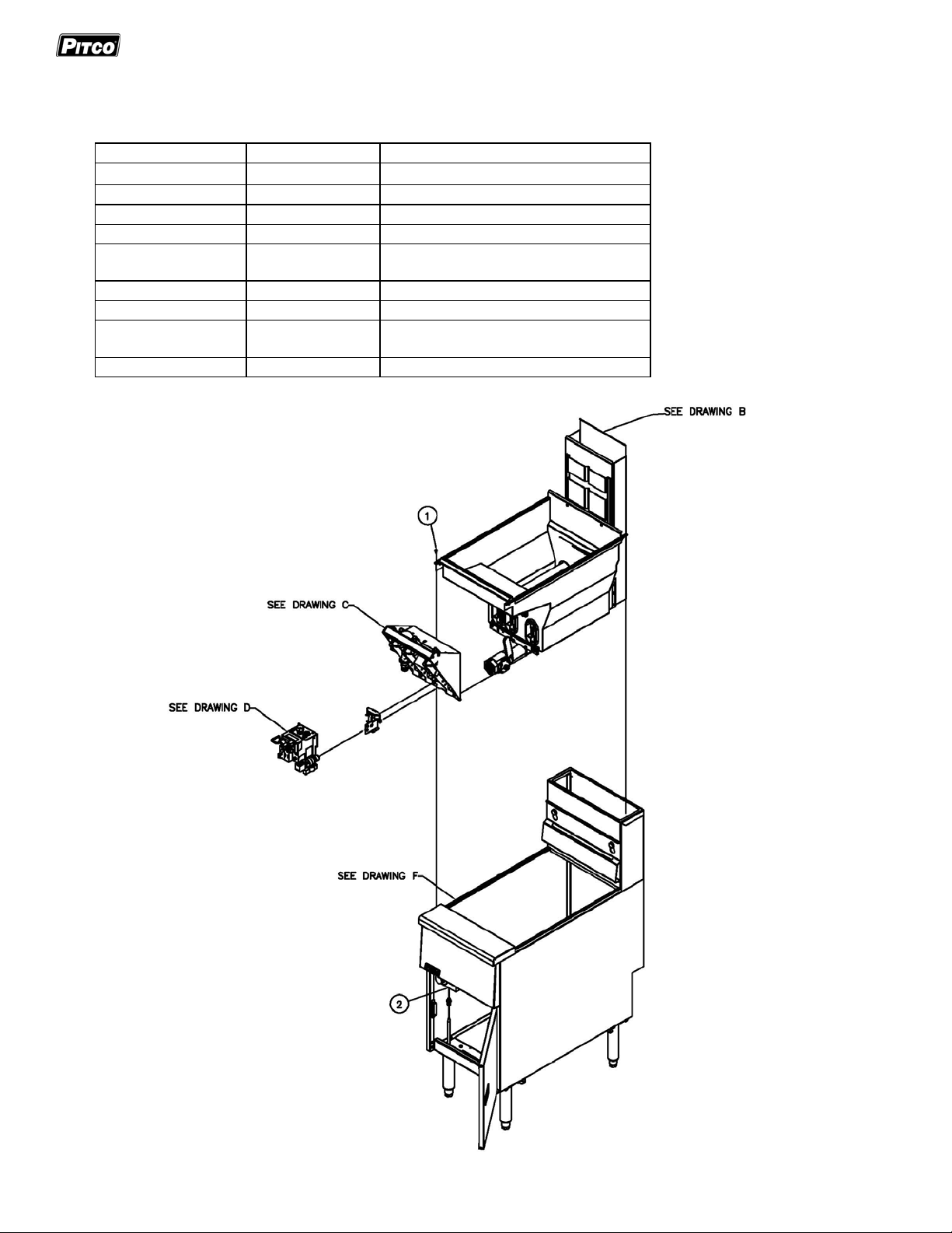
A) FRYER EXPLODED VIEWS
Fryer Exploded Parts List/View
ITEM # PART PART DESCRIPTION
1 PP10023 SCR,10-24 X 3/8 SLF TAP
2 B8030101 PG,ASSY HI-LIM & TSTAT SG14
See Drawing B Tank & Flue Page 6
See Drawing C Burner
See Drawing D Gas Train Page 8-9
See Drawing E Gas Conversion Page 10-11
See Drawing F Cabinet
See Drawing G Accessories Page 14/15
Assembly
Assembly
Page 7
Page 12/13
L22-382 Rev 1 (8/14)
5
Page 6

Exploded Parts-VF35 Gas Model
B) TANK & FLUE
Tank & Flue Exploded Parts List/View
ITEM # PART PART DESCRIPTION
1 B3333301 TK,WLDMT VF35
2 PP10368 VLV,BALL 1-1/4INCH NONLOCKING
3 P0092300 NUT, HEX 10-24 KEP ZN
4 P0075400
5 B3506301 FL,WLDMT VF35
6 PP11326 SCR,#14 X 1-1/2 HEX WH TAP
7 A1406702 CLP,LIM/TSTAT
SCR,10-24 X 1/2 SELF TAP
6
L22-382 Rev 1 (8/14)
Page 7
Exploded Parts-VF35 Gas Model
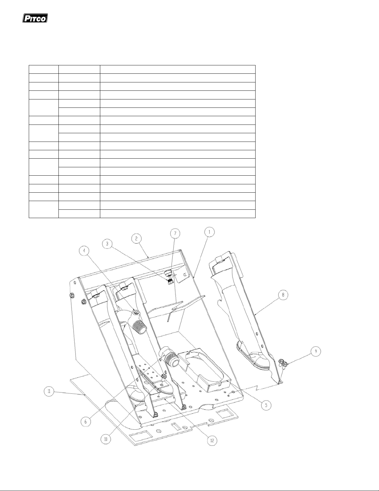
C) BURNER ASSEMBLY
Burner Assembly Exploded Parts List/View
ITEM # PART PART DESCRIPTION
1 A8033201 PIPING, BURNER BRACKET SGC
2 B8035301 PIPING, MANIFOLD WELDMENT
3 A7513706 ORIFICE, 2.2MM NAT
P6071354 PG,BNR VF35 #54 ORF LP
4 N/A PLUG, STEEL .125 MNPT RECESSED
5 A8031701 PIPING, BURNER SHIELD-NAT
A8034901 PIPING, BURNER SHIELD-LP
6 60127501 FITTING, ADAPTER MALE FLARE X .500 FPT
7 60129701 FITTING, BURNER
8 B8041901 PIPING, BURNER INCONEL 601 SCREEN SG-NAT
B8046101 PIPING, BURNER INCONEL 601 SCREEN SG-LP
9 N/A SCREW, 10-24 X .375 SELF TAPPING
10 A8031601 PIPING, CROSSOVER
11 A8047601 PG,GSKT BNR BRKT SGC,VF35
12 A8031701 PIPING, BURNER SHIELD, LH -NAT
A8034901 PIPING, BURNER SHIELD, LH - LP
L22-382 Rev 1 (8/14)
7
Page 8

Exploded Parts-VF35 Gas Model
D) GAS TRAIN
Gas Train Drawing Parts List
ITEM# PART# PART DESCRIPTION
1 60125901 TUBE, VENT GAS V A LVE
2 60127601 FITTING, A DA P TER FE M ALE SWIVEL X 1/2 MPT
3 A8029001-C PIPING, VALVE SHIELD
4 60127401 FITTING, ELBOW M ALE FLARE X MPT
5 P0007300 SCREW , 8-32 X 1/ 4 HE X HEAD SLO TTED ZN
6 A8029105 COUPLING, GAS SUPPLY SHORT SG, MKG
7 60128101 VA LVE, GA S SUPP LY SHUTOFF
8 60128015 TUBING, FLEXIBLE WITH FITTINGS 22 GAS
9
10 A 8035302 PIPING, P ILOT BRACK ET SG14 S G14R
11
12 60119001 TUBE, FLEXIBLE WITHOUT FITTINGS 18 X 1/4 OD
13 60088001 SCREW , 10-32 X 1/4 HE X HEA D S ST
14 PP 10084 SWITCH, HI-LIMIT LCM05030
15 A8028601-C PIP ING, BRACKET HI-LIMIT-THERMOS TAT SG MILLIVOLT
16 60125501 THERMOP ILE , MILLIVOLT
17 P 0190700 CLIP, CANOE FA S TEX
18 PP 10539 KNOB , THERMOS TAT WITH OFF, 200-400F & 100-200C
19 PP 10687 SCRE W, 6-32 X 313 THRUSS HEAD PHILLIPS ZN
20 B 6744401 WIRING, MILLIVOLT HI-LIMIT & THERMOS TAT SG
21 60125401 THERMOS TAT, RX MILLIVOLT 200-400F
60125201-C VALVE , GAS VS820 NAT
60125202-C VALVE , GAS VS820 LP
60128801 PILOT, REVERSE STANDING NAT SG
60128802 PILOT, REVERSE STANDING LP SG
8
L22-382 Rev 1 (8/14)
Page 9

Exploded Parts-VF35 Gas Model
Gas Train Drawing View
L22-382 Rev 1 (8/14)
9
Page 10
Exploded Parts-VF35 Gas Model
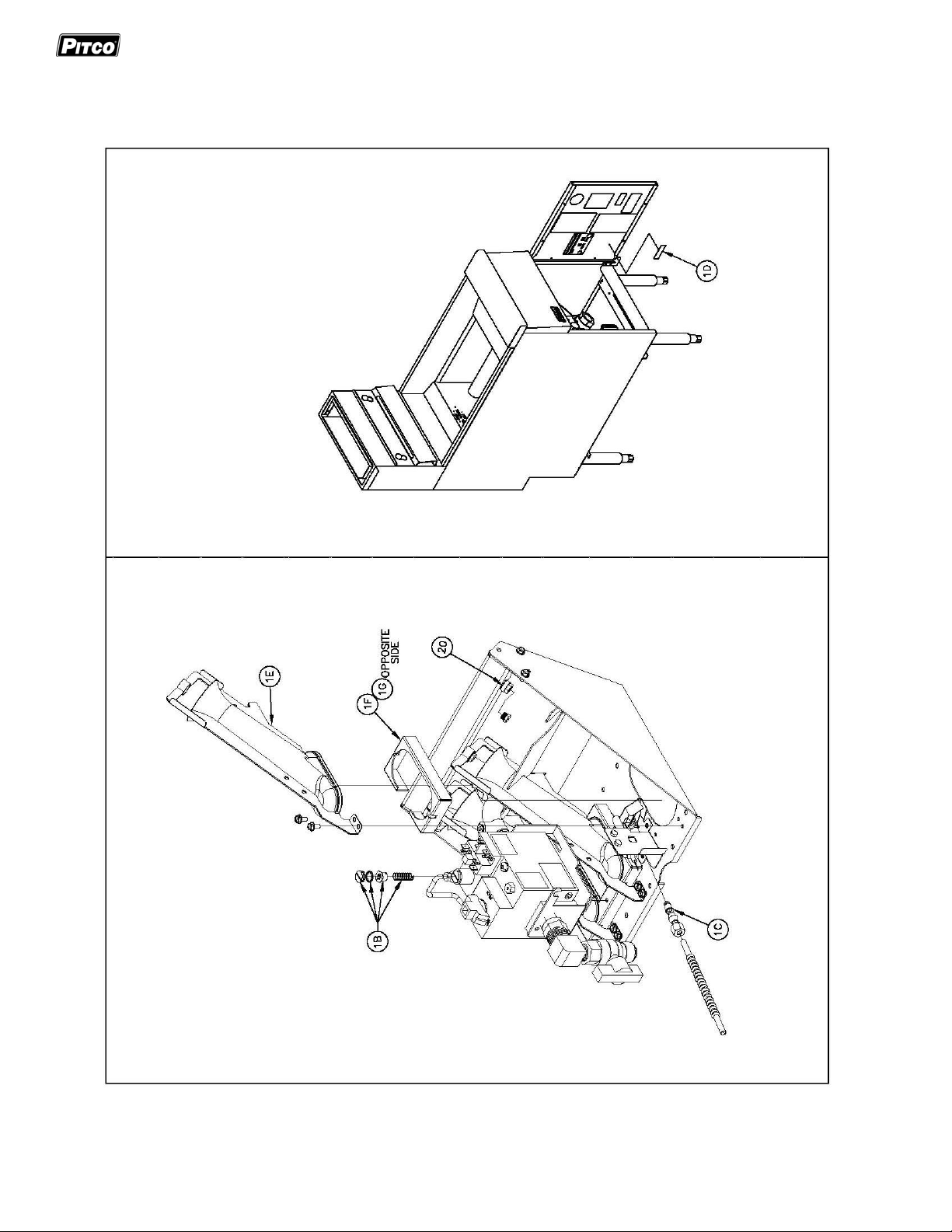
E) GAS CONVERSION KITS
Gas Conversion Kits Quick Reference
ITEM # PART # PART DESCRIPTION QTY
1 B8043267-C P G,CONV VF35 NAT TO LP
1A P6071354 ORIFICE TIP #54 DIA 3
1B 60126502 GAS VA LVE CONV K IT VS820 NAT TO LP 1
1C P 6071665 ORFICE P ILOT SPUD LP . 016 DIA 1
1D PP10426 GAS CONV NOTICE LAB E L NA T TO LP 1
1E B8046101 PG,BNR INC 600,20X20 SCRN 3
1F A8034905 PG, COLLA R B NR LP S T MG, SGH 1
1G A8034901 PG, COLLA R B NR LP F T LH MG, S GH 1
ITEM # PART # PART DESCRIPTION QTY
1 B8043266-C
1A A7513706
1B 60126501
1C P 6071666 ORFICE P ILOT SPUD NAT .022 DIA 1
1D PP10427 GAS CONV NOTICE LAB E L LP TO NAT 1
1E - - -
1F A8031801 PG, BNR SHLD S G14T* 1
1G A8031701 PG, B NR S HLD LH DG14 1
NATURAL TO LP
LP TO NATURAL
PG,CONV VF35 LP TO NAT
ORIFICE TIP 2 .2M M
GAS VALVE CONV KIT VS820 LP TO NAT
3
1
10
L22-382 Rev 1 (8/14)
Page 11
Exploded Parts-VF35 Gas Model
Gas Conversion Kits Quick Reference Drawing
L22-382 Rev 1 (8/14)
11
Page 12

Exploded Parts-VF35 Gas Model
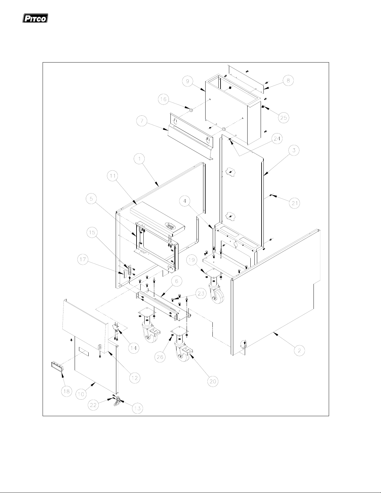
F) Standard Cabinet Drawing
Standard Cabinet Drawing List
IT EM # PART # PART DES CRIPTION
1 A1512002-C CAB INET SIDE LEF T-HAND
2 A1512004-C CAB INET SIDE RIGHT-HAND
3 A1635101-C CAB INET BA CK S G14, S G 14R, S G14T
4 A1635201-C CAB INET BA CK B OTTOM SG14,SG14R,SG14T
5 A1849601-C CAB INET FRONT SPACER SG14,SG14R,SG14T
6 A1235201-C CAB INET FRONT BOTTOM BRACE S G 14, S G14R, SG14T
7 A1105402-C BASKET HANGER SG14,SG14R,SG14T
8 A3526002-C FLUE RE AR HEAT DEFLECTOR SG14
9 A4106902-C SP LASH BA CK S G 14, S G14R, SG14T
10 B2304101-C DOOR ASSEMBLY SG14,SG14R,SG14T
11 B3630901-C FRONT PANE L TOP DECK WELDMENT SG14, S G14R, SG14T
12 B3632301-C FRONT PANE L ASSEMBLY SG14,SG14R,SG14T
13 B3801801 HINGE W E LDME NT LOW E R RIGHT HAND SG*
14 B3802401 HINGE W E LDM E NT UPPER RIGHT HAND SG*
15 A1847002 BRA CK E T MAGNE TIC CATCH
16 60132001 S TUD SPLA S H B A CK S CRE W ON
17 P6071300 MA GNE TIC CATCH STANDARD
18 PP 11006 HA NDLE DOOR RECESSED PLASTIC
19 SEE DRAWING G CASTER SWIVEL 9" NON-LOCKING
20 SEE DRAWING G CASTER SWIVEL 9" LOCKING
N/A SEE DRAWING G LEG SET W/HARDWARE 9" (4-PACK)
21 PP 10023 SCREW 10-24 X 3/8 SELF TAPPING
22 P0075400 SCREW 10-24 X 1/2 SELF TAPPING
23 P0020600 SCREW 1/4-20 X 5/8 HE X HEAD CAP ZN
24 60125801 S CREW 10-24 X 3/8 TRUSS HE A D SLOTTED LOCKING SST
25 60118201 B OLT 1/4-20 X 3/8 HEX FLANGE HEAD
26 P0093300 NUT HEX (KEP) 10-24 ZN
27
NOT SHOWN
(INCLUDES
ITEMS: 1-6 & 21)
B1822302-C CABINET ASSEMBLY STAND ALONE SG14,SG14R,SG14T
12
L22-382 Rev 1 (8/14)
Page 13
Exploded Parts-VF35 Gas Model
Standard Cabinet Parts Drawing
L22-382 Rev 1 (8/14)
13
Page 14

Exploded Parts-VF35 Gas Model
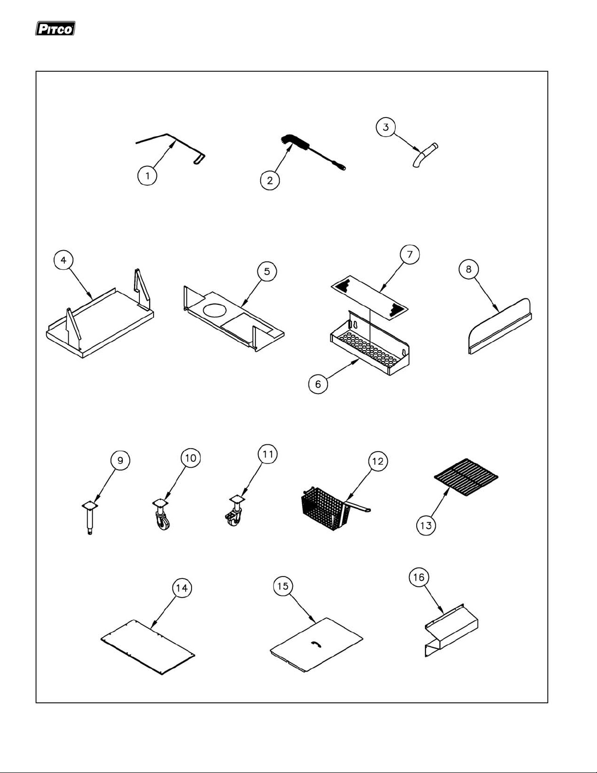
G) ACCESSORIES
Accessories Drawing Parts
ITEM # PART # PART DESCRIPTION
1 A3301001 CLEAN-OUT ROD
2 PP10056 CLEANING BRUSH NYLON
3 A2510101 DRAIN EXTENSION
4 CONTACT PITCO FRONT WORKSHELF
5 CONTACT PITCO SIDE WORKSEHELVE/DRAINBOARD
6 CONTACT PITCO REAR WORKSHELF
7 CONTACT PITCO REAR WORKSHELF INSERT
8 CONTACT PITCO SPLASH GUARD SIDE
9 60132401 9" LEG
B3900704 9" LEG SET OF 4 WITH HARDWARE
60115301 9" LEG WITH BOTTOM BOLT FLANGE ADJUSTABLE
10 PP10814 9" CASTER NON-LOCKING
B3901504 9" CASTER SET OF 4 (2 LOCKING, 2 NON-LOCKING)
B3902302 9" RIGID CASTER NON-LOCKING
11 PP10815 9" CASTER LOCKING
B3902304 9" RIGID CASTER LOCKING
12 P6072145 TWIN BASKET
P6072146 TWIN BASKET FINE MESH
P6072147 TRIPLE BASKET SG14, SG14R
P6072143 SQUARE BULK BASKET FRONT HANDLE
P6072144 SQUARE BULK BASKET FINE MESH FRONT HANDLE
13 P6073148 TUBE RACK
A4500201 TUBE SCREEN
B7425301-C FISH GRID SG14
14 A1842302-C CABINET BACK
15 B2101518-C TANK COVER ASSEMBLY
16 A3340601-C TANK BACK STANDOFF SG14
14
L22-382 Rev 1 (8/14)
Page 15
Exploded Parts-VF35 Gas Model
Accessories Drawing Parts List
L22-382 Rev 1 (8/14)
15
Page 16

p
In the event of problems with or questions
about your order, please contact the Pitco
Frialatorfactoryat
(603) 225-6684 World Wide
www.
itco.com
MAILING ADDRESS – P.O. BOX 501, CONCORD, NH 03302-0501
SHIPPINGADDRESS–10FERRYST.,CONCORD,NH03301
L22-382 Rev 1 (8/14)
In the event of problem s with or questions
about your equipment, please contact the
Pitco Frialator Authorized Service and
Parts representative (ASA P) covering your
area, or contact Pitco at the numbers
to the left.
listed
 Loading...