

Page 1
IMPORTANT FOR FUTURE REFERENCE
Please complete this information and retain this manual
for the life of the equipment:
Model #: ___________________________
Serial #: ___________________________
Date Purchased: ____________________
Installation & Operation Manual
Model SRTE
Floor Model Electric Rethermalizer
Built after 8/2005
ENGLISH
L20-292, rev. 1 (05/11)
Page 2

TO THE PURCHASER, OWNER AND STORE MANAGER
Please review these warnings prior to posting them in a prominent location for reference.
WARNING
DO NOT store or use gasoline or other flammable
vapors and liquids in the vicinity of this or any other
appliance.
WARNING
Improper installation, alteration, service or
maintenance can cause property damage, injury or
death. Read the installation, operating and
maintenance instructions thoroughly before installing
or servicing this appliance.
WARNING
Installation, maintenance and repairs should be
performed by a Pitco Authorized Service and Parts
(ASAP) company technician or other qualified
personnel. Installation, maintenance or repairs by an
unauthorized and unqualified personnel will void the
warranty.
WARNING
Installation and all connections must be made
according to national and local regulations and codes
in force.
WARNING
A country approved all pole circuit breaker with a
minimum open contact gap of 3mm must be used for
proper installation. (CE countries)
WARNING
During the warranty period if a customer elects to use
a non-original part or modifies an original part
purchased from Pitco and/or its Authorized Service
and Parts (ASAP) companies, this warranty will be
void. In addition, Pitco and its affiliates will not be
liable for any claims, damages or expenses incurred
by the customer which arises directly or indirectly, in
whole or in part, due to the installation of any
modified part and/or received from an unauthorized
service center.
WARNING
This appliance, when installed, must be electrically
grounded in accordance with local codes, or in the
absence of local codes, with the National Electrical
Code, ANSI/NFPA 70, or the Canadian Electrical Code,
CSA C22.2, as applicable.
WARNING
Adequate means must be provided to LIMIT the
movement or this appliance without depending on the
electrical cord connection. Single appliances
equipped with legs must be stabilized by installing
anchor straps. All appliances equipped with casters
must be stabilized by installing restraining chains.
WARNING
DO NOT alter or remove structural material on the
appliance to accommodate placement under a
ventilation hood.
WARNING
This appliance is intended for professional use only
and should be operated by fully trained and qualified
personnel.
WARNING
If the supplied power cord is damaged, it must be
replaced by a Pitco Authorized Service and Parts
(ASAP) company technician, or a similarly qualified
person in order to avoid a hazard.
WARNING
The power supply must be disconnected before
servicing, maintaining or cleaning this appliance.
WARNING
The appliance is NOT jet stream approved. DO NOT
clean the appliance with a water jet.
WARNING
DO NOT attempt to move this appliance or transfer hot
liquids from one container to another when the unit is
at operating temperature or filled with hot liquids.
Serious personal injury could result if skin comes in
contact with the hot surfaces or liquids.
WARNING
DO NOT sit or stand on this appliance. The
appliance’s front panel, tank, splash back, tank cover,
workshelf, drain board is not a step. Serious injury
could result from slipping, falling or contact with hot
liquids.
WARNING
NEVER use the appliance as a step for cleaning or
accessing the ventilation hood. Serious injury could
result from slips, trips or from contacting hot liquids.
WARNING
The water level should be maintained at the level line.
DO NOT turn the appliance on until the heating
elements are fully covered with water at all times.
Serious injury could result from hot steam vapors off
the heating element.
WARNING
If overflow drain is not equipped or if overflow drain
stop is used, do not leave appliance unattended while
filling with water. Over filling the appliance can cause
serious injuries and damage the equipment.
WARNING
Completely shut the appliance down when the water is
being drained from the appliance. This will prevent the
appliance from heating up during the draining and
filling process. Serious injury and heating element
damage can occur.
WARNING
This appliance is intended for indoor use only.
WARNING
DO NOT operate appliance unless all panels and
access covers are attached correctly.
WARNING
It is recommended that this appliance be inspected by
a qualified service technician for proper performance
and operation on a yearly basis.
ii L20-292, rev. 1 (05/11)
Page 3

SRTE: Electric Floor Model Rethermalizer TABLE OF CONTENTS
1. INSTALLATION......................................................................................1
1.1. CHECKING YOUR NEW APPLIANCE..........................................................................................1
1.2. INSTALLATION CLEARANCES...................................................................................................2
1.3. LEG/CASTER INSTALLATION AND LEVELING.........................................................................2
1.4. PLUMBING CONNECTIONS.........................................................................................................3
1.4.1. WATER INLET CONNECTIONS.............................................................................................3
1.4.2. DRAIN CONNECTIONS..........................................................................................................3
1.5. ELECTRICAL CONNECTIONS.....................................................................................................4
1.6. VENTILATION AND FIRE SAFETY SYSTEMS............................................................................5
1.7. INSPECTION..................................................................................................................................5
1.8. INITIAL CLEANING .......................................................................................................................5
2. OPERATION...........................................................................................6
2.1. FILLING THE APPLIANCE............................................................................................................8
2.1.1. FILLING THE COOKER TANK ...............................................................................................8
2.1.2. FILLING THE COOKER TANK WITHOUT THE AUTOMATIC LEVEL SYSTEM...................8
2.2. APPLIANCE START UP................................................................................................................9
2.3. COOKING.......................................................................................................................................9
2.3.1. SIMMER MODE ......................................................................................................................9
2.3.2. BOIL MODE.............................................................................................................................9
2.3.3. TIMER OPERATION.............................................................................................................10
2.3.4. ADDITIONAL CONTROLLER FUNCTIONS.........................................................................10
2.3.5. COOKING TIPS.....................................................................................................................10
2.4. APPLIANCE SHUTDOWN...........................................................................................................10
3. PREVENTATIVE MAINTENANCE.......................................................11
3.1. DAILY PREVENTATIVE MAINTENANCE ..................................................................................11
3.1.1. APPLIANCE INSPECTION...................................................................................................11
3.1.2. CLEANING THE COOK TANK..............................................................................................11
3.1.3. CLEANING THE CABINET...................................................................................................11
iii
Page 4

TABLE OF CONTENTS
3.2. MONTHLY PREVENTATIVE MAINTENANCE ...........................................................................12
3.2.1. DELIMING.............................................................................................................................12
3.3. ANNUAL/PERIODIC PREVENTATIVE MAINTENANCE AND INSPECTION............................12
3.3.1. HEATING ELEMENT ............................................................................................................12
3.3.2. TEMPERATURE PROBE & HIGH LIMIT PROBE................................................................12
3.3.3. CONTROLLER......................................................................................................................12
3.3.4. CONTROL BOX & ELECTRICAL COMPONENTS...............................................................12
3.3.5. TANK.....................................................................................................................................13
3.3.6. DRAIN SYSTEM ...................................................................................................................13
4. TROUBLESHOOTING .........................................................................14
4.1. POWER FAILURE........................................................................................................................14
4.2. HIGH TEMPERATURE LIMIT......................................................................................................14
4.3. DRAIN VALVE INTERLOCK.......................................................................................................14
4.4. TROUBLESHOOTING CHART ...................................................................................................15
4.5. CONTROLLER WARNING DISPLAYS.......................................................................................15
iv L20-292, rev. 1 (05/11)
Page 5
SRTE: Electric Floor Model Rethermalizer INSTALLATION
1. INSTALLATION
1.1. CHECKING YOUR NEW APPLIANCE
Your new Pitco appliance has been carefully packed into one crate. Every effort has been made to
ensure that it is delivered to you in perfect condition. As you unpack your new appliance, inspect each
of the pieces for damage. If something is damaged, DO NOT sign the bill of lading. Contact the
shipper immediately; the shipper is only responsible for 15 days after delivery. Check the packing list
enclosed with your appliance to ensure that you have received all the parts to the appliance. If you
are missing any parts, contact the dealer from whom the appliance was purchased. As you unpack
the appliance and its accessories be careful to keep
the weight of the appliance evenly distributed.
Refer to the table below to identify which
accessories should be included with your appliance.
Locate your Pitco model number and serial number
on the inner door of the appliance and the find the
date purchased. Write this information on the front
cover of this manual for future reference.
If you have completed the above steps that are
applicable to the appliance you purchased, the
appliance is now ready to be installed. Although it
may be possible for you to install and set up your
new appliance, it is STRONGLY recommended that
you have this done by qualified professionals. A
qualified professional will ensure that the installation
is safe and meets local building and fire codes.
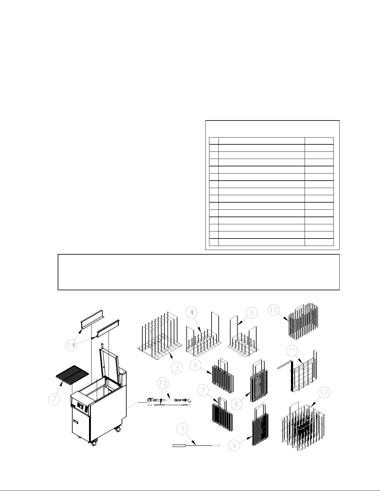
# Description SRTE
1 Cleaning brush Standard
2 Tube Rack Standard
3 8 Product Vertical Food Rack Optional
4 8 Product Rack Optional
5 6 Product Food Rack Optional
6 Wide Product Suitcase Optional
7 Narrow Product Suitcase Optional
8 Tall Wide Product Suitcase Optional
9 Tall Narrow Product Suitcase Optional
10 Wide basket Optional
11 Narrow Basket Optional
12 8 Product basket Optional
13 Water Quick Disconnect & Lanyard Optional
14 1/3 Pan Rails Optional
Accessories
WARNING
DO NOT sit or stand on this appliance. The appliance’s front panel, tank, splash back, tank
cover, workshelf, drain board is not a step. Serious injury could result from slipping, falling
or contact with hot liquids.
1
Page 6
INSTALLATION
q
1.2. INSTALLATION CLEARANCES
The clearances shown below are for combustible and non-combustible installations and will allow for
safe and proper operation of your appliance.
Combustible Construction Non Combustible Construction
Inches (centimeters) Inches (centimeters)
Back
Sides
Counter
In addition to the above clearances there must also be at least 16 inches (40.64cm) of aisle space in
front of the unit.
6.0" (15.24cm) 0.0" (0.0cm)
6.0" (15.24cm) 0.0" (0.0cm)
6.0" (15.24cm) 6.0" (15.24cm)
WARNING
DO NOT obstruct the flow of ventilation, or air openings
around the appliance. Adequate clearance around the
appliance is necessary for servicing and proper
component ventilation. Ensure that you meet the
minimum clearance requirements specified in this manual.
CAUTION
To prevent equipment damage and/or personal injury, do
not tilt the appliance onto any two of its casters or legs, or
pull the appliance by the splash back.
1.3. LEG/CASTER INSTALLATION AND LEVELING
When you receive your appliance it is completely assembled with the possible exception of the legs
(or casters). This appliance must be installed with legs or casters; it cannot be curb mounted. Curb
mounting will seriously inhibit this appliance’s ability to effect proper component ventilation. The
legs/casters must be installed before connecting the appliance to the power supply. The legs provide
the necessary height to meet sanitation requirements and assure adequate air supply for the
electrical component ventilation. Use the following procedure.
Required tools: 7/16 “ wrench and socket and a large pair of water pump pliers.
1. Lay the appliance on its back, being careful not to damage the splash back by pulling on it.
Protect the outside of the appliance with cardboard or a drop cloth when laying it down.
2. Attach each leg/caster with the hex head screws and nuts supplied. Each leg/caster requires
four ¼-20 x 5/8” hex head screws and nuts. Insure that all screws are tight.
DO NOT install this appliance next
to a deep fat fryer. A splash over of
water into the hot oil may cause a
flash fire.
This appliance must be installed
with the legs or casters provided by
the manufacturer.
WARNING
WARNING
3. Mount the screws from the inside of the appliance with the nut on the outside (bottom) of the
appliance. The nuts have lock washers attached to them, therefore it is not necessary to use
separate lock washers.
WARNING
DO NOT install legs or casters, or perform
leveling procedure when appliance is in operation
or full of hot li
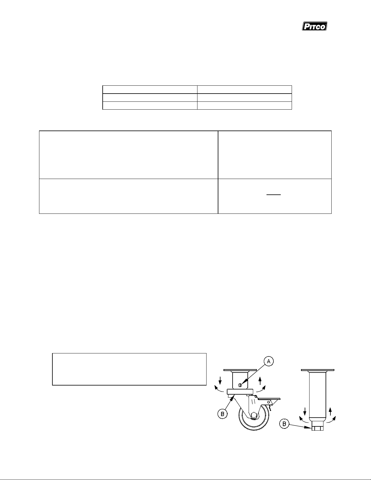
4. When all four legs/casters are securely mounted,
stand the unit up, being careful not to put too
much weight on any one leg. Adjust the height
and level the appliance by adjusting the leveling
devices (B) with water pump pliers. On casters,
loosen 2 screws (A) before leveling, make your
height adjustments, then retighten.
2 L20-292, rev. 1 (05/11)
uids. Serious injury could result.
Page 7

SRTE: Electric Floor Model Rethermalizer INSTALLATION
1.4. PLUMBING CONNECTIONS
The plumbing installation should be done by a licensed plumber and must comply with local and
national codes.
1.4.1. WATER INLET CONNECTIONS
If a faucet or water fill option is equipped on your appliance connections to a potable water supply
will be required. If a single water connection is required it is recommended that the appliance is
connected to hot water supply. This will greatly decrease the time it takes for the appliance to
reach operating temperature. Prior to installation, a water treatment specialist should inspect the
water supply. Water hardness should contain no more then 2.0 grains/gallon. The pH level
should be between 6.5 and 8.0. These conditions can be obtained with the use of a properly
maintained water softener. The incoming water pressure should be between 20 psi (1.38 bars) to
60 psi (4.14 bars). For higher water pressures, a high-pressure regulator must be installed to
inlet plumbing to avoid damage caused by water hammer. The maximum allowable incoming
water temperature is 180°F (82°C). Have your water tested and record the measured values
below.
Water Quality Checklist
Measured Range OK
Temperature 180°F (82°C) Max.
Hardness 2.0 Grains/Gal. Max.
pH 6.5 to 8.0
Pressure 20 psi to 60 psi
1.4.2. DRAIN CONNECTIONS
Each tank has a drain that can be inserted into a drainage system. Each tank also has an
overflow line. The overflow connection is after the drain valve to provide an unobstructed
overflow path. The drain and overflow line for each tank is connected together to form a common
drain line. Drain connections for this appliance will be either 1” female NPT or 1” male NPT.
WARNING
Do NOT install a floor drain directly under the cabinet of the appliance.
Steam from a floor drain can limit the life of internal components.
When water is at a high
temperature and high
pressure, excessive
splashing of hot water
may occur that could
result in injury.
WARNING
SRTE SRTE-2
1) ½” male NPT Water Inlet 2) 1” NPT Drain Outlet
3
Page 8

INSTALLATION
y
g
1.5. ELECTRICAL CONNECTIONS
It is advised that this power supply be plugged into a wall receptacle that is controlled by the
ventilation control. This will prevent the appliance from being operated without the ventilator on. If
your appliance requires an electrical connection, the power requirements are listed below.
Voltage/Phase KW Amps
200VAC, single phase 7.4 37
208VAC, single phase 8.0 38
220VAC, single phase 8.9 41
240VAC, single phase 10.7 44
200VAC, three phase 7.4 21
208VAC, three phase 8.0 22
A country approved all pole circuit breaker with a
minimum open contact gap of 3mm must be used
for proper installation. (CE countries)
Connecting the appliance to the wrong power suppl
may damage the appliance and void the warranty.
WARNING
CAUTION
220VAC, three phase 8.9 24
240VAC, three phase 10.7 26
346/200VAC, three phase 7.4 12
380/220VAC, three phase 8.9 14
400/230VAC, three phase 9.8 14
415/240VAC, three phase 10.7 15
This appliance must be connected to a power supply
having the same voltage and phase as specified on
the data plate located on the inside of the appliance
door.
WARNING
WARNING
DO NOT attempt to connect the appliance to an electrical supply other then that indicated on
the data plate. Electrical connection should be performed by qualified personnel.
WARNING
The appliance must be grounded in accordance with local code; if there is no local code,
comply with the NEC and ANSI/NFPA No. 70 latest edition (for US and Canadian installations).
In all other cases, refer to local and national codes and regulations. To comply with European
requirements, European models are equipped with an equalization-bonding clamp. An
equalization bonding lead must be connected to this clamp to provide sufficient protection
against potential difference. This clamp, located on the rear of the appliance is marked with
the following universal symbol.
WARNING
All copper wiring for this appliance must be made in accordance
with the wiring diagram(s) located on the appliance.
WARNING
If this appliance is permanently connected to fixed wiring, it must
be connected by means of copper wires having a temperature
WARNING
The electrical connection used by this
appliance must comply with local codes.
If there are no local codes that apply,
refer to the National Electrical Code
(NEC), ANSI/NFPA 70 for installation in
the US. In Canada, refer to CSA Standard
C22.2 and local codes. In all other cases,
refer to local and national codes and
re
ulations.
WARNING
This equipment must be installed so that
the plug is accessible unless other means
for disconnection from the power supply
(e.g. a circuit breaker) is provided.
Phillips Screwdriver Required
To Access
Electrical Connections
1) 1” (2.54cm) Access Hole
2) Connection Points
1/2” (1.27cm) Allen
Wrench Required
3) Ground Connection
Flat head
screwdriver required
4 L20-292, rev. 1 (05/11)
Page 9

SRTE: Electric Floor Model Rethermalizer INSTALLATION
1.6. VENTILATION AND FIRE SAFETY SYSTEMS
Your new appliance must have proper ventilation to function safely and properly. It is very important
to install a fire safety system. Your ventilation system should be designed to allow for easy cleaning.
Frequent cleaning and proper maintenance of the ventilation system and the appliance will redu ce the
chances of fire. Ventilation and fire safety systems must comply to local and national codes. Refer to
ANSI 83.11 for a list of reference documents that will provide guidance on ventilation and fire safety
systems.
1.7. INSPECTION
Before you begin filling and operating the appliance, perform the following visual checks:
After the appliance is in its permanent location, check the
levelness. Any additional leveling that is necessary can be
performed as previously described.
Ensure that the probe, heating element and high temperature
limit is in place and secure. Check the high limit bulb
mounting screws to ensure that they are tight.
Review the installation portion of this manual and ensure that
all steps have been followed and executed properly.
CAUTION
Be careful not to disturb the probe and high temperature
limit during operation and cleaning of this appliance.
1) Probe
2) High Temperature Limit
3) Heating Element
1.8. INITIAL CLEANING
When your appliance is shipped, many of its parts are covered with a thin coat of oil for protection.
Before the appliance is ready for cooking it must be cleaned. This will remove the oil coating and any
foreign matter that may have accumulated during storage and shipment. Refer to the following
procedure to clean the appliance.
WARNING
Wear protective gloves and clothing when cleaning and draining the appliance and
when disposing of water. The water is extremely hot and can cause severe injuries.
CAUTION
DO NOT leave the appliance unattended during cleaning. Never let the water level
go below the heating element.
1. Read the “operation” section of this manual prior to filling or operating the appliance.
2. The following steps should be followed using a grease dissolving commercial cleaner.
WARNING
Use a commercial grade cleaner formulated to effectively clean and sanitize food
contact surfaces. Read the directions and precautionary statements before use.
Particular attention must be paid to the concentration of cleaner and the length of
time the cleaner remains on the food contact surfaces.
3. Following the manufacturer’s directions, clean the tank interior and all other food cont act
surfaces.
4. When cleaning is complete, rinse the inside of the tank thoroughly with cool water. Continue to
rinse the tank until the cleaner has been completely and thoroughly rinsed from the tank.
5. Using a clean dry cloth, wipe out all of the water.
5
Page 10

OPERATION
2. OPERATION
An operator’s manual for your appliance’s specific control type should be included with this manual.
Refer to that manual prior to operating this appliance.
2.1. OPERATIONAL FEATURES
The diagram below outlines some of the key operational components of your appliance. Refer to the
following sections of this manual to learn more about these features.
6 L20-292, rev. 1 (05/11)
Page 11

SRTE: Electric Floor Model Rethermalizer OPERATION
1. Cook Tank
2. Controller (Not on all Models)
Controls the water temperature inside the cook tank.
Optional timers are located on the controller (if equipped).
If the controller has an ON/OFF button, it will be used to turn ON the controller as well as other
features on the appliance.
3. Door (Shown Open)
Provides access to the drain valve handle, high temperature reset button and gas valve, pilot,
burners and shutoff valves.
4. Drain Valve Handle (Shown in the closed position)
Opens the drain valve so water can be drained from the cook tank.
The drain valve interlock feature will stop the appliance from heating if the drain valve is opened.
5. Drain Outlet
Water exits the cook tank through the drain outlet when draining or overflowing.
6. Overflow Line
When the cook tank water level reaches the overflow, water will flow unobstructed through the
overflow line and eventually exit the appliance through the drain outlet.
7. High Temperature Reset Button
This button may need to be pressed in the event that the high temperature limit has tripped.
8. Tank Cover (shown in UP position)
Keeps heat inside and debris outside of the cook tank.
9. Tank Cover Latch
Holds the tank cover in the up position when adding or removing product from the cook tank.
10. ON/OFF Switch
Turns the appliance ON and OFF. Some controllers require that they are turned ON by another
button after the ON/OFF switch is in the ON position.
11. Fill Bypass Switch
When this switch is held down the cook tank will fill with water regardless of the water level.
12. Main Water Shutoff Valve
Shuts off the water supply to all tanks inside the cabinet.
13. Tank Water Shutoff Valve
Shuts off the water supply to the closest tank.
14. Solenoid Water Valve
Turns the supply of water to the tank ON and OFF.
This valve is controller by the water level sensors inside the tank.
Valve can also be controlled by the fill bypass switch.
15. Electrical Control Box
DANGER: High voltage present. Do NOT open.
Electrical components that control the heating elements are located inside this box.
16. Entrance Box
DANGER: High voltage present. Do NOT open.
The main power for the appliance is connected inside this box.
7
Page 12

OPERATION
2.2. FILLING THE APPLIANCE
2.2.1. FILLING THE COOKER TANK
It is recommended that the cooker tank is filled with hot water. This will greatly decrease the time
it takes for the appliance to reach operating temperature. Refer to the following procedure to fill
the cook tank prior to operation.
This appliance is not designed for cooking
with oil. Fill with potable water only.
1. Ensure that the drain valve is closed.
CAUTION
DRAIN VALVE CLOSED
2. Fill the tank with water until the water reaches the water
level line(s).
3. This appliance is equipped with an automatic water level
maintaining system. To fill the tank with water, Press
the unit’s I/0 (ON/OFF) switch to the I (ON) position.
This will cause the tank to fill with water. The tank will continue to fill until the water level
reaches the level sensors. When both of the active water level sensors are covered the
solenoid valve will close stopping the flow of water. During normal operation the automatic
fill system will maintain the water level at the proper height.
NOTE: If the water control system turns on while the main burners are running, the main
burners will turn off. This is Normal and will not affect the operation of the appliance. When the
tank refills to the high level probe, the main burners will relight.
2.2.2. FILLING THE COOKER TANK WITHOUT THE AUTOMATIC LEVEL SYSTEM
Although the water fill system is completely automatic, the tank can be filled without putting the
appliance into full operational mode. To fill the tank without operating the appliance press the
rocker switch to the
completely filled.
Water must completely cover the heating elements at all times while appliance is on.
symbol. Continue to hold down the switch until the appliance is
WARNING
Model Capacity
SRTE
Tank Capacity
17-1/2 Gal.
(66.2 Liters)
8 L20-292, rev. 1 (05/11)
Page 13

SRTE: Electric Floor Model Rethermalizer OPERATION
2.3. APPLIANCE START UP
Refer to the following procedure to start the appliance prior to operation.
1. Ensure that the drain valve is closed.
2. Fill the cook tank with water. (See section 2.1 “Filling the Appliance”)
3. Turn the I/0 (ON/OFF) switch to the I (ON) position.
WARNING
NEVER operate the appliance with an empty cook tank. It may void the warranty.
Adding water after the elements have been heated may cause injuries from hot
splattering liquids and steam.
4. The controller may need to be turned on. Press the
*
button to turn the controller on.
*The specified button may appear slightly different then shown. Refer to the operator’s
manual for your appliance’s specific control type to determine the exact appearance of eac h
button and display.
5. The appliance is now on and heating the water in the cook tank.
WARNING
Water must completely cover the heating elements at all times while appliance is on.
2.4. COOKING
It is important to keep the cook tank full of water to minimize the chance of boiling the appliance dry
and to keep the water at a level that will provide optimum cooking performance. To ensure the quality
of the food you cook in this appliance, follow the preparation instructions from the food manufacturer.
WARNING
Dry fired elements are extremely hot, will shorten its service life and may void your warranty.
Maximum Recommended Product Capacity (after 195°F preheat)
2160 in³ Total (12x 180 in³ bags or equivalent) per tank
2.4.1. SIMMER MODE
Simmer mode maintains the water temperature to just below boiling. This mode is used to reheat
food or as a “stand by” mode. When the appliance is turned on, it will be in simmer mode.
2.4.2. BOIL MODE
Boil mode consistently heats the water so that the water will boil. Use of this mode is not
recommended for your appliance. Not all control types include boil mode.
9
Page 14

OPERATION
2.4.3. TIMER OPERATION
Not all control types include timers. Timers provide accurate cook times for multiple product
quantities and types. Refer to the operator’s manual for your appliance’s specific control type to
determine how to set the cook timers if equipped.
To start a timer: Press the appropriate timer button.
Typical Timer Bu ttons*
2.4.4. ADDITIONAL CONTROLLER FUNCTIONS
Some controllers have additional functions not described in this manual. If your appliance’s
controller has additional functions, refer to the controller’s operation manual to access these
functions.
2.4.5. COOKING TIPS
*Timer buttons may appear slightly different then shown.
Refer to the operator’s manual for your appliance’s
specific control type to determine the exact appearance of
each timer button.
Always follow the food manufacturer’s directions
and only use vacuum-sealed products in this
appliance.
Some products can be reheated and held at the
same temperature. If this is the case, the
product may be held in this appliance while still
in its vacuum-sealed bag. No separate holding
device required.
Product bag size can be important in reaching
the shortest retherm times. Thin bags typically
retherm faster then thicker ones.
Always allow a gap between product bags. This will allow the hot water to circulate around
the entire surface of the product bag, creating good heat transfer and ultimately shorter
retherm times.
Do NOT retherm in boiling water. Boiling water increases your energy and water
consumption and furthermore this appliance is NOT recommended for boiling.
Always follow proper food safety. Refer to FDA and the food manufacturer’s guidelines for
proper handling of the vacuum-sealed product.
2.5. APPLIANCE SHUTDOWN
Refer to the following procedure to shutdown the appliance.
Product 140F 200F
Frozen 40 min. 9-10 min.
Thawed 30 min. 7-8 min.
Typical Retherm Times
Appliance Temperature
This table is for reference only.
Please refer to the product
manufacturer’s specifications to
determine exact cook times.
1. If the appliance is equipped with a controller it should be turned OFF. Refer to the operator’s
manual for your appliance’s specific control type to determine how to do this.
2. If the appliance is equipped with a I/0 (ON/OFF) switch, turn it to the 0 (OFF) position.
10 L20-292, rev. 1 (05/11)
Page 15

SRTE: Electric Floor Model Rethermalizer PREVENTATIVE MAINTENANCE
3. PREVENTATIVE MAINTENANCE
3.1. DAILY PREVENTATIVE MAINTENANCE
Performing the preventative maintenance steps below on a daily basis will keep your equipment safe
and at peak performance. During the cooking process, starch build up will form on the temperature
probes, tank and heating element. It may be necessary to clean these components more then once a
day.
WARNING
The power supply must be disconnected before cleaning and servicing this appliance!
3.1.1. APPLIANCE INSPECTION
Check that the high temperature limit, temperature probe and elements are in the correct
position and secured in place.
Check that wires and cords are not frayed or loose in and out of the cabinet.
Check around the appliance for loose parts or accessories that need to be secured or other
foreign items (ex: Aerosol cans) that should be removed from the area.
Check for water leaks around the drain lines and water supply in and out of the cabinet and
around the appliance.
WARNING
Wear protective gloves and clothing when cleaning and draining the appliance and
when disposing of water. The water is extremely hot and can cause severe injuries.
3.1.2. CLEANING THE COOK TANK
1. Turn the appliance off.
WARNING
Read the operation section of this manual prior to filling or operating the appliance.
2. Scrub the tank, basket hanger, baskets, heating element and temperature probe using a
Scotchbrite™ or other abrasive pad with a commercial type cleaner specifically designed fo r
cleaning and sanitizing food contact surfaces. Follow the directions and familiarize yourself
with the safe use of this cleaner prior to using it to clean the appliance. Care must be taken
to remove all the foreign material on the tank and on components in the tank.
WARNING
DO NOT leave the appliance unattended during cleaning.
3. When cleaning is complete, rinse the inside of the tank and its components thoroughly with
cool water. Continue to rinse at least twice or until the cleaner has been completely and
thoroughly rinsed from the tank.
3.1.3. CLEANING THE CABINET
1. The inside of the cabinet should be cleaned with a clean dry cloth removing oil, dust, dirt and
cooking debris on all accessible surfaces and components.
2. The outside of the cabinet should be cleaned with a wetted cloth and mild detergent to
remove oil, dust, dirt and debris. Be careful not to introduce the detergent into the tank and
food zone regions of the appliance.
11
Page 16

PREVENTATIVE MAINTENANCE
3.2. MONTHLY PREVENTATIVE MAINTENANCE
Water can leave mineral deposits inside the tank. Performing the monthly preventative maintenance
steps below will keep your equipment safe and at peak performance. It may be necessary to clean
these components more then once a month.
3.2.1. DELIMING
1. Read the “operation” section of this manual prior to filling or operating the appliance.
2. Following the manufacturer’s deliming instructions, remove deposits from the tank’s interior.
3. When cleaning is complete, rinse the inside of the tank and its components thoroughly with
cool water. Continue to rinse at least twice or until the cleaner has been completely and
thoroughly rinsed from the tank.
4. Using a clean dry cloth, wipe out all of the water.
3.3. ANNUAL/PERIODIC PREVENTATIVE MAINTENANCE AND INSPECTION
This section should ONLY be performed by a qualified service technician as part of a regular kitchen
maintenance program. This inspection should take place a minimum of once a year by an Authorized
Service Technician recommended by Pitco. It may be
necessary perform this inspection more then once a year.
The power supply must be
3.3.1. HEATING ELEMENT
Check if the element is mechanically strong and in
good condition. Look for scale build up and inspect for
signs of repeated dry firing.
Verify element wires are in good working condition. Look for damage to wires o r frayed
insulation. Check that the insulation is dry.
Verify that bulkhead connections/nut is tight and leak free. Look for water stains and wet
surfaces.
Verify amp-draw is within range as compared to the information on the data plate.
disconnected before cleaning
and servicing this appliance!
WARNING
3.3.2. TEMPERATURE PROBE & HIGH LIMIT PROBE
Verify probes are in good working condition. Check for damage and that the fasteners are
tightly secured to the tank.
Verify compression fittings are leak free.
Check wiring for loose electrical connections.
3.3.3. CONTROLLER
Perform the following inspection if the appliance is equipped with a temperature controller.
Verify that the controller is in good mechanical condition. Check all lights, displays and
switches to assure that they are working properly. Examine overlay for damage that could
allow moisture to enter.
Check for loose electrical connections.
Verify simmer temperature. Check temperature 1” above controller probe, if necessary check
probe resistance.
Check drain valve interlock (if provided) to ensure that the appliance stops heating whe n the
drain valve is open.
3.3.4. CONTROL BOX & ELECTRICAL COMPONENTS
Verify that heating contactors are in good condition. Check for worn or pitted contacts. Verify
that wires are tight and in good condition.
Verify that all components (transformer, terminal block, relays, drain switches, etc…) are in
good condition. Verify that wires are tight and in good condition.
Verify enclosures are free of leaks. Check for water stains and wet surface s.
Verify that the covers and panels are in tact and provide a safe condition. Check for loose
parts.
Verify power cord is in good condition. Check for frayed or exposed wires. Verify that the
insulation is in good condition and the attachment to the appliance is tight.
12 L20-292, rev. 1 (05/11)
Page 17

SRTE: Electric Floor Model Rethermalizer PREVENTATIVE MAINTENANCE
3.3.5. TANK
Verify that the tank is in good condition. Check for scale build up and inspect for signs of
corrosion. Verify that tank is leak free. Check drain overflow (if equipped) for scale build up
and debris blockage.
3.3.6. DRAIN SYSTEM
Verify that drain valve is in good condition. Check for leaks in the seal area and fitting region.
Verify that drain lines are leak free, kink free and in good condition. Check for scale build up
and debris blockage. Verify that the clamps and connections are securely tightened.
13
Page 18

TROUBLESHOOTING
4. TROUBLESHOOTING
4.1. POWER FAILURE
If electric power is removed for any reason, the appliance will shut down. To restart the appliance,
follow the appliance start up procedure in section 2.2.
CAUTION
DO NOT attempt to operate this appliance during a power outage.
4.2. HIGH TEMPERATURE LIMIT
This appliance is equipped with a high temperature limit switch. The high temperature limit switch will
stop the appliance from functioning if the internal cook tank reaches an unsafe temperature. In the
event that the high temperature limit has tripped, Please refer to the following procedure to reset the
switch.
1. Turn the appliance off.
2. Allow the appliance ample time to cool to room
temperature.
3. Add water to the cook tank as needed.
4. Press the high temperature reset button if equipped.
5. The high limit switch is now reset and the appliance is
ready for start up.
High Temperature Reset Button
(Not on all models)
WARNING
DO NOT add water to the tank until it has been given ample time to cool down. Failure
to do so may result in damage to the appliance and/or injury to the operator.
4.3. DRAIN VALVE INTERLOCK
If your appliance is equipped with a drain valve interlock circuit, the appliance will stop heating if the
tank drain valve is opened. In some cases the appliance will turn off. Refer to the following
procedure to resume operation after the drain valve interlock is tripped.
1. Turn the appliance OFF (if not already OFF).
2. Close the tank drain valve and fill the tank with water.
3. Turn the appliance ON.
14 L20-292, rev. 1 (05/11)
Page 19

SRTE: Electric Floor Model Rethermalizer TROUBLESHOOTING
4.4. TROUBLESHOOTING CHART
Problem Probable Causes Corrective Actions
No power to appliance. Check main building power supply.
Circuit Breaker tripped. Reset circuit breaker.
Controller does not
activate.
I/0 Switch in 0 position.
Flip I/0 switch to I position and turn on
controller.
Controller not turned on. Turn on controller.
Power Cord loose or not connected. Connect power cord.
Autofill does not add
water.
Autofill does not shut
off when full.
Controller displays
that it is heating but
water will not heat.
Water not turned on. Turn on water.
Lower water level sensor is wet. Dry off sensor.
Dirty upper water level sensor. Clean upper water level sensor.
Insufficient mineral content in water. Add 1/8 cup baking soda to cook tank.
Autofill system has cutoff heat.
High temperature limit has tripped
Allow Autofill system to fill tank and
restore heat.
Allow appliance to cool and reset High
temperature limit.
4.5. CONTROLLER WARNING DISPLAYS
If your applaince is equipped with a temperature controller it may display the following warnings on its
display.
Display Problem Action
Water temperature
Wait for appliance to heat up.
is low.
Incorrect probe
Contact Authorized Service Company.
reading.
Water level is low. Turn off appliance. Allow ample time for appliance to
cool before filling with water and turning on.
Incorrect probe
Contact Authorized Service Company.
reading.
Drain valve is open
while controller is
Turn off appliance. Close drain valve before turning
appliance back on.
on.
15
Page 20

In the event of problems with or
questions about your order, please
contact the Pitco Frialator factory at:
(603) 225-6684 World Wide
Website Address: www.pitco.com
MAILING ADDRESS – P.O. BOX 501, CONCORD, NH 03302-0501
SHIPPING ADDRESS – 10 FERRY ST., CONCORD, NH 03301
L20-292, rev. 1 (05/11)
In the event of problems with or questions
about your equipment, please contact the
Pitc o F r i al a to r Authorized Service and Parts
representative (ASAP) covering your area, or
contact Pitco at the numbers listed to the left.
 Loading...