

Page 1

ARROW IV
Courtesy of Bomar Flying Service
www.bomar.biz
MAINTENANCE MANUAL
CARD 1 OF 3
PA-28RT-201 ARROW IV
PA-28RT-201T TURBO ARROW IV
PIPER AIRCRAFT CORPORATION
(PART NUMBER 761 694)
1A1
Page 2
PIPER AIRCRAFT
PA-28RT-201 / 201T
MAINTENANCE MANUAL
INTRODUCTION.
This PIPER AIRCRAFT Maintenance Manual is prepared in accordance with the GAMA (General
Aviation Manufacturers Association) format. This maintenance manual is divided into various Groups which
enable a broad separation of contents (Chapters) within each group.
The various Chapters are broken down into major systems such as Electrical Power, Flight Controls, Fuel,
Landing Gear, etc. The System/Chapters are arranged more or less alphabetically rather than by precedence or
importance. All System/Chapters are assigned a number, which becomes the first element of a standardized
numbering system. Thus the element “32” of the number series 32-00-00 refers to the System/Chapter on
“Landing Gear.” All information pertaining to the landing gear will be covered in this System/Chapter.
The major System/Chapters are then broken down into Sub-System/Sections. These sections are identified
by the second element of the standardized numbering system. The number “40” of the basic number series 3240-00 is for the “Wheels and Brakes” portion of the landing gear.
The individual units within a Sub-System/Section may be identified by a third element of the standardized
numbering system, such as 32-40-0l. This number could be assigned by the manufacturer to fit the coverage
requirements of the publication.
Example:
CHAPTER/SYSTEM
LANDING GEAR
32-40-01
This manual does not contain hardware callouts for installation. Hardware callouts are only indicated
where a special application is required. To confirm the correct hardware used, refer to the PA-28RT-201/201T
Parts Catalog P/N 761 693, and FAR 43 for proper utilization.
SUB-SYSTEMS
WHEELS AND BRAKES
INDIVIDUAL UNITS
NOSE WHEEL REMOVAL
1A2
Introduction
Page - 1
December 1, 1978
Page 3

VENDOR PUBLICATIONS.
ENGINE (LYCOMING):
Overhaul Manual = AVCO LYCOMING - OVERHAUL MANUAL
Parts Catalog = AVCO LYCOMING - P/N PC-102
Operators Handbook =AVCO LYCOMING O-360, HO-360, IO-360,
ENGINE (CONTINENTAL):
Overhaul Manual = CONTINENTAL - OVERHAUL MANUAL
Parts Catalog = CONTINENTAL - Form No. X-30031A
Operators Handbook = CONTINENTAL - Form No. X-30512
PROPELLER:
Overhaul Instructions = HARTZELL COMPACT CONSTANT SPEED
Service Manual = McCAULEY C200 SERIES CONSTANT
MAGNETOS:
Installation, Operation
and Maintenance
Instructions = D-2000 and D-2200 SERIES MAGNETO
PIPER AIRCRAFT
PA-28RT-201 / 201T
MAINTENANCE MANUAL
DIRECT DRIVE ENGINE - P/N 60294-7
Avco Lycoming Division
Williamsport, Pa. 17701
Avco Lycoming Division
Williamsport, Pa. 17701
AIO-360, HIO-360, LIO-360 and TIO-360
SERIES AIRCRAFT ENGINES - P/N 60297-12
Avco Lycoming Division
Williamsport, Pa. 17701
Form No. X-30030A
Teledyne Continental Motors
Aircraft Products Division
Mobile, Alabama 36601
Teledyne Continental Motors
Aircraft Products Division
Mobile, Alabama 36601
Teledyne Continental Motors
Aircraft Products Division
Mobile, Alabama 36601
and FEATHERING PROPELLER - P/N 113A
Hartzell Propeller Inc.
Piqua, Ohio 45356
SPEED PROPELLERS - P/N 780630
McCauley Accessory Division
3535 McCauley Drive
Vandalia, Ohio 45377
IGNITION SYSTEM - P/N L-928
Bendix Electrical Components Division
Sidney, New York 13838
AUTOPILOT: CENTURY 41 AUTOPILOT, Edo-Aire Mitchell
Box 610, Mineral Wells, Texas 76067
1A3
Revised: August 17, 1982
Introduction
Page - 2
Page 4

PIPER PUBLICATIONS.
ELECTRONICS:
AutoFlight II Service
Manual = Piper P/N 761 481
Pitch Trim Service
Manual = Piper P/N 753 771
AutoControl III B and
Altimatic III B Service
Manual = Piper P/N 753 502
Altimatic III C Service
Manual = Piper P/N 761 602
79 Vero Beach Avionics
Wiring Diagrams
Manual = Piper P/N 761 713
AEROFICHE:
PA-28RT-201/201T
Parts Catalog = Piper P/N 761 693
INSPECTION:
PA-28RT-201/201T
Program Inspection
Manual = Piper P/N 761 736
Inspection Forms = Piper P/N 230 818
PIPER AIRCRAFT
PA-28RT-201 / 201T
MAINTENANCE MANUAL
1A4
Introduction
Page - 3
Added: August 17, 1982
Page 5

PIPER AIRCRAFT
PA-28RT-201 / 201T
MAINTENANCE MANUAL
AEROFICHE EXPLANATION AND REVISION STATUS
Maintenance manual information incorporated in this set of Aerofiche cards is arranged in accordance with
the general specifications of Aerofiche adopted by the General Aircraft Manufacturer’s Association. The
information compiled in this Aerofiche maintenance manual will be kept current by revisions distributed
periodically. These revisions supersede all previous revisions and are complete Aerofiche card replacements
and supersede Aerofiche cards of the same number in the set.
Identification of revised material:
Revised text and illustrations are indicated by a black vertical line along the left-hand margin of the frame,
opposite revised, and added material. Revision lines indicate only current revisions with changes and additions
to existing text and illustrations. Changes in capitalization, spelling, punctuation, indexing, the physical
location of the material or complete page additions are not identified by revision lines.
A reference and record of the material revised is included in each chapter’s Table of Contents/Effectivity.
The codes used in the effectivity columns of each chapter are defined as follows:
TABLE OF CONTENTS/EFFECTIVITY CODES
Original Issue: None
First Revision: Revision Identification, (1R Month-Year)
Second Revision: Revision Identification, (2R Month-Year)
All subsequent revisions will follow with consecutive revision numbers
such as 3R, 4R, etc., along with the appropriate month-year.
Added Subject: Revision Identification, (A Month-Year)
1A5
Introduction
Page - 4
Interim Revision: September 21, 1986
Page 6

PIPER AIRCRAFT
PA-28RT-201 / 201T
MAINTENANCE MANUAL
Revisions to Maintenance Manual 761 694 issued December 1, 1978 are as follows:
Revisions
ORG 781201 December 1, 1978 1, 2, and 3
PR790223 February 23, 1979 1, 2, and 3
PR791106 November 6, 1979 1, 2, and 3
PR800818 August 18, 1980 1, 2, and 3
PR810724 July 24, 1981 1, 2, and 3
PR811221 December 21, 1981 1, 2, and 3
PR820817 August 17, 1982 1, 2, and 3
PR830713 July 13, 1983 1, 2, and 3
PR840808 August 8, 1984 1, 2, and 3
IR860730 July 30, 1986 (Interim) 1
IR860921 September 21, 1986 (Interim) 1
IR950227 February 27, 1995 (Interim)* 1, 2, and 3
*INTERIM CHANGE TO MAINTENANCE MANUAL 761-694
Chapters 5, 6, and 27 of Card 1, Chapters 32 and 51 of Card 2, and Chapter 71 of
Card 3 have been revised. There are no other changes included in this interim change
revision. Please discard your current cards 1, 2, and 3, and replace them with the
revised ones.
Date Aerofiche Card Effectivity
SERIAL NUMBER INFORMATION
PA-28RT-201, Arrow IV - 1979 - Serial Numbers 28R-7918002 to 28R-7918267 inclusive
PA-28RT-201, Arrow IV - 1980 - Serial Numbers 28R-8018001 to 28R-8018106 inclusive
PA-28RT-201, Arrow IV - 1981 - Serial Numbers 28R-8118001 to 28R-8118082 inclusive
PA-28RT-201, Arrow IV - 1982 - Serial Numbers 28R-8218001 to 28R-8218026 inclusive
PA-28RT-201T, Turbo Arrow IV - 1979 - Serial Numbers 28R-7931002 to 28R-7931310 inclusive
PA-28RT-201T, Turbo Arrow IV - 1980 - Serial Numbers 28R-8031001 to 28R-8031178 inclusive
PA-28RT-201T, Turbo Arrow IV - 1981 - Serial Numbers 28R-8131001 to 28R-8131208 inclusive
PA-28RT-201T, Turbo Arrow IV - 1982 - Serial Numbers 28R-8231001 to 28R-8231080 inclusive
PA-28RT-201T, Turbo Arrow IV - 1983 - Serial Numbers 28R-8331001 to 28R-8331051 inclusive
PA-28RT-201T, Turbo Arrow IV - 1984 - Serial Numbers 28R-8431001 to 28R-8431032 inclusive
PA-28RT-201T, Turbo Arrow IV - 1985 - Serial Numbers 28R-8531001 to 28R-8531015 inclusive
PA-28RT-201T, Turbo Arrow IV - 1986 - Serial Numbers 28R-8631001 and 28R-8631005 inclusive
PA-28RT-201T, Turbo Arrow IV - 1987 - Serial Numbers 28R-8631002 to 28R-8631004 inclusive
Serial Numbers 2831001 to 2831033 inclusive
PA-28RT-201T, Turbo Arrow IV - 1988 - Serial Numbers 2831034 to 2831038 inclusive
1A6
Introduction
Page-5
Interim Revision: February 27, 1995
Page 7

PIPER AIRCRAFT
PA-28RT-201 / 201T
MAINTENANCE MANUAL
GAMA SYSTEM/CHAPTER INDEX GUIDE
SYST SUB-SYST AEROFICHE
CHAP SECTION TITLE GRID NO.
4 AIRWORTHINESS LIMITATIONS 1A18
5 TIME LIMITS/MAINT CHECKS 1A22
6 DIMENSIONS AND AREAS 1B16
7 LIFTING AND SHORING 1C5
8 LEVELING AND WEIGHING 1C9
9 TOWING AND TAXIING 1C14
10 PARKING AND MOORING 1C18
11 REQUIRED PLACARDS 1C22
12 SERVICING 1D5
20 STANDARD PRACT - AIRFRAME 1E14
21 ENVIRONMENTAL SYSTEM 1E21
22 AUTOFLIGHT 1H1
23 COMMUNICATIONS 1H8
24 ELECTRICAL POWER 1H17
27 FLIGHT CONTROLS 1J17
28 FUEL 2A18
29 HYDRAULIC POWER 2B17
32 LANDING GEAR 2D4
33 LIGHTS 2F19
34 NAVIGATION & PITOT/STATIC 2G7
35 OXYGEN SYSTEM 2G21
37 VACUUM SYSTEM 2H17
1A7
Introduction
Page - 6
Revised: July 13, 1983
Page 8

PIPER AIRCRAFT
PA-28RT-201 / 201T
MAINTENANCE MANUAL
GAMA SYSTEM/CHAPTER INDEX GUIDE (cont)
SYST SUB-SYST AEROFICHE
CHAP SECTION TITLE GRID NO.
39 ELECTRICAL/ELECTRONIC PANELS AND
MULTI-PURPOSE PARTS 2I2
51 STRUCTURES 2I6
52 DOORS 2J1
55 STABILIZERS 2J10
56 WINDOWS 2J19
57 WINGS 2J24
61 PROPELLER 3A18
70 STANDARD PRACTICES - ENGINE 3B9
71 POWER PLANT 3B12
73 ENGINE FUEL AND CONTROL 3C12
74 IGNITION 3D7
77 ENGINE INDICATING 3F16
78 EXHAUST 3G1
79 OIL SYSTEM 3G6
80 STARTING 3G10
81 TURBINES 3H1
91 CHARTS AND WIRING DIAGRAMS 3H7
95 SPECIAL PURPOSE EQUIPMENT 3K1
1A8
Introduction
Page - 7
Interim Revision: February 27, 1995
Page 9

PIPER AIRCRAFT
PA-28RT-201 / 201T
MAINTENANCE MANUAL
LIST OF ILLUSTRATIONS
FIGURE NO. SUBJECT GRID NO.
6-1. Three View of PA-28RT-201T 1B22
6-2. Three View of PA-28RT-201 1B23
6-3. Station Reference Lines of PA-28RT-201/201T 1C1
6-4. Access Plates and Panels 1C3
7-1. Jacking Arrangements 1C7
8-1. Leveling Longitudinally 1C12
8-2. Leveling Laterally 1C12
8-3. Weighing Arrangement 1C12
11-1. Placards and Decals 1C24
12-1. Servicing Points (PA-28RT-201) 1D8
12-2. Servicing Points (PA-28RT-201T) 1D9
12-3. Fuel Strainer 1D10
12-4. Lubrication Chart (Landing Gear, Main) 1D24
12-5. Lubrication Chart (Landing Gear, Nose) 1E2
12-6. Lubrication Chart (Control System) 1E4
12-7. Lubrication Chart (Cabin Door, Baggage Door
and Seat) 1E8
12-8. Lubrication Chart (Lycoming Power Plant, Propeller
and Control Pivot Points) 1E9
12-9. Lubrication Chart (Continental Power Plant, Propeller
and Control Pivot Points) 1E10
12-10. Lubrication Chart (Back-Up Extender) 1E11
12-11. Lubrication Chart (Air Conditioning Condenser) 1E12
20-1. Torque Wrench Extension 1E16
20-2. Method of Installing Rod End Bearings 1E17
21-1. Cabin Heater and Defroster (PA-28RT-201) 1F7
21-2. Cabin Heater and Defroster (PA-28RT-201T) 1F8
21-3. Overhead Vent System and Fresh Air System “Not
Available with Air Conditioning” 1F9
21-4. Air Conditioning System Installation 1F11
21-5. Service Valves 1F16
21-6. Test Gauge and Manifold Set 1F16
21-7. Manifold Set Operation 1F18
21-8. Leak Test Hookup 1F19
21-9. Evacuation Hookup 1F21
21-10. Charging Stand 1F24
21-11. Charging Hookup 1F24
21-12. Top Dead Center Casting Mark (Sankyo Compressor) 1G6
21-13. Rotation of Clutch Front Plate (Sankyo Compressor
Oil Check) 1G6
21-14. York Compressor and Fabricated Oil Dipstick
(PA-28RT-201) 1G7
21-15. Compressor and Alternator Belt Installation
(PA-28RT-201) 1G9
21-16. Magnetic Clutch (York Compressor) 1G10
1A9
Introduction
Page - 8
Revised: July 13, 1983
Page 10

PIPER AIRCRAFT
PA-28RT-201 / 201T
MAINTENANCE MANUAL
LIST OF ILLUSTRATIONS (cont)
FIGURE NO. SUBJECT GRID NO.
21-17. Condenser Air Scoop Installation 1G14
21-18. Expansion Valve 1G15
21-19. Components Installation 1G17
21-20. Adjustment of Air Conditioning Throttle Switch
(PA-28RT-201) 1G17
21-21. Air Conditioning Wiring Schematic 1G19
23-1. ELT Portable Folding Antenna (Narco) 1H12
23-2. ELT Using Fixed Aircraft Antenna (Narco) 1H12
23-3. ELT Schematics 1H16
24-1. Lamp-Bank Load 1I8
24-2. Exploded View of Alternator (Chrysler) 1I10
24-3. Checking Field Coil Current Draw 1I10
24-4. Testing Field Circuit 1I10
24-5. Testing Positive Rectifiers With C-3829 Tester 1I12
24-6. Testing Negative Rectifiers With C-3829 Tester 1I12
24-7. Rectifier End Shield and Stator Assembly 1I12
24-8. Testing Positive Rectifiers With Test Lamp 1I14
24-9. Testing Negative Rectifiers With Test Lamp 1I14
24-10. Rectifier and Heatsink Assembly Removal 1I14
24-11. Rectifier End Shield Assembly 1I14
24-12. Testing Stator 1I16
24-13. Removal of Pulley 1I16
24-14. Removal of Bearing 1I16
24-15. Removal of Rectifier End Shield Bearing 1I16
24-16. Testing Rotor for Ground 1I17
24-17. Testing Rotor for Opens or Shorts 1I17
24-18. Installation of Grease Retainer 1I18
24-19. Installation of Rectifier End Shield Bearing 1I18
24-20. Installation of Drive End Shield Bearing 1I18
24-21. Installation of Pulley 1I18
24-22. Installation of Insulators 1I20
24-23. Installation of Positive Rectifier Assembly 1I20
24-24. Installation of Capacitor 1I20
24-25. Installation of Battery Output Insulator 1I20
24-26. Installation of Negative Rectifier Assembly 1I21
24-27. Installation of Stator 1I21
24-28. Exploded View of Alternator (Prestolite) 1I23
24-29. Removal of Slip Ring End Bearing 1I24
24-30. Removal of Rectifier 1I24
24-31. Removal of Drive End Head 1J2
24-32. Removal of End Head Bearing 1J2
24-33. Testing Rotor for Ground 1J2
24-34. Testing Rotor for Shorts 1J2
1A10
Introduction
Page - 9
Revised: July 13, 1983
Page 11

PIPER AIRCRAFT
PA-28RT-201 / 201T
MAINTENANCE MANUAL
LIST OF ILLUSTRATIONS (cont)
FIGURE NO. SUBJECT GRID NO.
24-35. Installation of Drive End Head 1J4
24-36. Installation of Rectifier 1J4
24-37. Terminal Assembly (Prestolite) 1J4
24-38. Slip Ring End Bearing Assembly 1J6
24-39. Testing Alternator 1J6
24-40. Brush Installation 1J7
24-41. Internal Wiring Diagram 1J7
27-1. Rod End Installation Method 1K3
27-2. Control Column Assembly 1K5
27-3. Aileron Controls (Typical) 1K8
27-4. Aileron Rigging 1K12
27-5. Bellcrank Rigging Tool 1K12
27-6. Aileron Rigging Tool 1K13
27-7. Rudder and Steering Pedal Assembly 1K15
27-8. Rudder Controls 1K17
27-9. Rudder Rigging Tool 1K18
27-10. Clamping Rudder Pedals 1K18
27-11. Rudder Rigging 1K18
27-12. Rudder and Stabilator Travel Adjustments 1K22
27-13. Rudder Trim Control 1K22
27-14. Stabilator Controls 1K24
27-15. Stabilator and Stabilator Trim Travel Adjustments 1L1
27-16. Stabilator Rigging Tool 1L1
27-17. Methods of Securing Trim Cables 1L4
27-18. Stabilator Trim Control 1L5
27-19. Flap Controls 1L9
27-20. Flap Step Adjustment 1L11
27-21. Flap Rigging Tool 1L11
27-22. Flap Rigging 1L14
28-1. Fuel System Diagram (PA-28RT-201) 2A24
28-2. Fuel System Diagram (PA-28RT-201T) 2B1
28-3. Engine Primer System Placards (PA-28RT-201T) 2B2
28-4. Locking Fuel Cap Assembly 2B4
28-5. Fuel Filter Bowl and Screen 2B5
28-6. Auxiliary Fuel Pump Variable Resistor 2B7
28-7. Tolerances; Union Nut and Tubing Nut 2B12
28-8. Fuel Gauge 2B14
29-1. Schematic Diagram of Hydraulic System 2B20
29-2. Schematic Diagram of Hydraulic System 2B21
29-3. Hydraulic System Installation 2B22
29-4. Hydraulic System Installation 2B23
29-5. Hydraulic Pump/Reservoir, Exploded View 2C12
29-6. Test and Adjustment of Hydraulic Pump 2C13
29-7. Checking Aligning Brackets of Gear Back-Up Extender
Actuator 2C17
29-8. Gear Back-Up Extender Actuator 2C18
29-9. Nose Gear Actuating Cylinder 2C22
1A11
Introduction
Page - 10
Revised: August 8, 1984
Page 12

PIPER AIRCRAFT
PA-28RT-201 / 201T
MAINTENANCE MANUAL
LIST OF ILLUSTRATIONS (cont)
FIGURE NO. SUBJECT GRID NO.
29-10. End Gland Locking Device 2C24
29-11. Main Gear Actuating Cylinder 2D1
32-1. Main Gear Oleo Strut Assembly 2D16
32-2. Main Gear Installation 2D17
32-3. Main Gear Service Tolerances 2D19
32-3a. Aligning Main Gear 2E3
32-4. Nose Gear Oleo Strut Assembly 2E7
32-5. Nose Gear Installation 2E9
32-5a. Nose Gear Service Tolerances 2E10
32-6. Nose Gear Adjustment (PA-28RT-201) 2E16
32-7. Nose Gear Adjustment (PA-28RT-201T) 2E17
32-8. Clamping Rudder Pedals in Neutral Position 2E19
32-9. Rudder Pedals at Neutral Angle 2E19
32-10. Nose Gear Door Retraction Mechanism(PA-28RT-201) 2E20
32-11. Nose Gear Door Retraction Mechanism (PA-28RT-201T) 2E21
32-12. Nose Wheel Assembly 2E24
32-13. Main Wheel Assembly 2F1
32-14. Wheel Brake Assembly (30-55) 2F2
32-15. Removal of Anchor Bolt 2F4
32-16. Installation of Anchor Bolt 2F5
32-17. Brake System Installation 2F7
32-18. Brake Master Cylinder (Hand Parking Brake) 2F8
32-19. Toe Brake Installation 2F9
32-20. Brake Cylinder (17000) (Toe Brake) 2F10
32-21. Brake Cylinder (10-30) (Toe Brake) 2F11
32-22. Adjustment of Nose Gear Down Limit Switch 2F15
32-23. Adjustment of Main Gear Down Limit Switch 2F15
32-24. Throttle Warning Switches 2F17
33-1. Annunciator Panel 2G1
33-2. Strobe Light Connections 2G4
34-1. Pitot-Static System Installation 2G10
35-1. Fixed Oxygen System 2G24
35-2. Portable Oxygen System 2H1
35-3. Test Apparatus for Testing Oxygen System 2H4
35-4. Oxygen Tubing Installations 2H5
35-5. Installation of Swagelok Fittings 2H8
51-1. Skin Materials and Thickness 2I9
51-1a. Baggage Compartment Inspection Holes Cutout Details 2I12
51-2. Surfaces Scratches, Abrasions or Ground-in-Dirt 2I16
51-3. Deep Scratches, Shallow Nicks and Small Holes 2I17
51-4. Mixing of Epoxy Patching Compound 2I17
51-5. Welding Repair Method 2I19
51-6. Repairing of Cracks 2I19
51-7. Various Repairs 2I20
51-8. Repair of Stress Lines 2I22
51-9. Repair of Impacted Damage 2I22
52-1. Installation of Door Snubber 2J7
1A12
Introduction
Page - 11
Interim Revision: February 27, 1995
Page 13

PIPER AIRCRAFT
PA-28RT-201 / 201T
MAINTENANCE MANUAL
LIST OF ILLUSTRATIONS (cont)
FIGURE NO. SUBJECT GRID NO.
55-1. Stabilator Installation 2J13
55-2. Stabilator Balance Configuration 2J14
55-3. Vertical Fin Installation 2J15
55-4. Rudder Installation 2J17
55-5. Rudder Balancing 2J18
56-1. Windshield Installation (Typical) 2J22
56-2. Side Window Installation, Single Pane (Typical) 2J23
57-1. Wing Installation 2K3
57-2. Aileron and Flap Installation 2K8
57-3. Aileron Balance Configuration 2K11
61-1. Propeller Installation (Hartzell) 3A21
61-2. Propeller Blade Minor Repair 3A23
61-3. Propeller Governor 3A24
61-4. Propeller Controls 3B2
61-5. Propeller Installation (Hartzell) 3B4
61-6. Propeller Blade Minor Repair 3B5
61-7. Propeller Governor 3B7
71-1. Engine Installation (PA-28RT-201T) 3B21
71-2. Engine Cowling Installation (PA-28RT-201T) 3B24
71-3. Engine Installation (PA-28RT-201) 3C7
71-4. Engine Cowling Installation (PA-28RT-201) 3C11
73-1. Schematic Diagram of Fuel Injection System 3C15
73-2. Fuel Injector Nozzle Assembly 3C17
73-3. Engine Controls 3C17
73-4. Idle Speed and Mixture Adjustment Points 3C19
73-5. Sectional View of Altitude Compensating Fuel Pump Assembly 3C19
73-6. Exhaust Bypass Screw 3C21
73-7. Fuel Injector 3D1
73-8. Schematic Diagram of RSA Fuel Injector System 3D2
73-9. Fuel-Air Bleed Nozzle 3D4
73-10. Adjustments of Engine Controls 3D4
74-1. Magneto Assembly 3D12
74-2. Contact Spring Inspection 3D13
74-3. Contact Points 3D14
74-4. Impulse Coupling 3D15
74-5. Flyweight Clearance of Impulse Coupling 3D15
74-6. Rotor Holding Tool Installed 3D15
74-7. Timing Kit Installed 3D15
74-8. Cast-In Timing Marks 3D17
74-9. Fabricated Pointer 3D17
74-10. Engine Timing Marks 3D17
74-11. Removing Spring From Lead Assembly 3D20
1A13
Introduction
Page-12
Interim Revision: February 27, 1995
Page 14

PIPER AIRCRAFT
PA-28RT-201 / 201T
MAINTENANCE MANUAL
LIST OF ILLUSTRATIONS (cont)
FIGURE NO. SUBJECT GRID NO.
74-12. Assembly Tool 3D21
74-13. Assembly Tool Application 3D22
74-14. Measuring Lead Assembly Length 3D23
74-15. Ferrule Seating Tool 3D24
74-16. Measuring Wire From Top of Ferrule 3D24
74-17. Needle 3D24
74-18. Installing Grommet Over Lead Assemblies 3D24
74-19. Lead Assembly Installed in Grommet 3E2
74-20. Wire Doubled Over For Installation of Eyelet 3E2
74-21. Ignition Schematic 3E3
74-22. Removing Frozen Spark Plug 3E5
74-23. Contact Points 3E9
74-24. Rotor Holding Tool Installed 3E10
74-25. Timing Kit Installed 3E10
74-26. Aligning Timing Marks 3E10
74-27. Checking Flyweight Clearance of Impulse Coupling 3E10
74-28. Engine Timing Marks 3E13
74-29. Magneto Adjustment Limits 3E13
74-30. Magneto Timing Marks 3E14
74-31. Removing Spring From Lead Assembly 3E15
74-32. Assembly Tool 3E16
74-33. Using Assembly Tool 3E16
74-34. Measuring Lead Assembly Length 3E17
74-35. Cutting Metallic Braid From End of Lead 3E17
74-36. Unbraiding Metallic Shielding 3E17
74-37. Forming Shielding Around Ferrule 3E19
74-38. Ferrule Seating Tool 3E19
74-39. Needle 3E19
74-40. Measuring Wire From Top of Ferrule 3E21
74-41. Installing Grommet Over Lead Assemblies 3E21
74-42. Lead Assembly Installed in Grommet 3E21
74-43. Wire Doubled Over For Installation of Eyelet 3E21
74-44. Removing Spark Plug Frozen to Bushing 3E22
74-45. Ignition Switch Wire Positions 3F1
78-1. Exhaust System Inspection Points 3G4
80-1. Exploded View of Gear Reduction Starting Motor 3G15
80-2. Turning Starting Motor Commutator 3G17
80-3. Testing Motor Armature for Shorts 3G17
80-4. Testing Motor Fields for Grounds 3G17
80-5 No-Load Test Hook-Up 3G19
80-6. Stall-Torque Hook-Up 3G19
81-1. Schematic Diagram of Turbocharger System 3H4
1A14
Introduction
Page - 13
Revised: July 13, 1983
Page 15

PIPER AIRCRAFT
PA-28RT-201 / 201T
MAINTENANCE MANUAL
LIST OF ILLUSTRATIONS (cont)
FIGURE NO. SUBJECT GRID NO.
ELECTRICAL SCHEMATICS
—NOTE—
Refer to Grid 313 for Electrical Schematic Index.
95-1. Tire Balancer Fixture 3K4
95-2. Control Surface Balancing Tool 3K5
95-3. Ignition Harness Ferrule Seating Tool 3K6
95-4. Needle 3K6
95-5. Assembly Tool for Ignition Harness Insulating
Sleeve Installation 3K6
95-6. Charging Stand 3K7
95-7. York Compressor and Fabricated Oil Dipstick
(PA-28RT-201) 3K7
95-8. Fabricated Gear Back-Up Extender Actuator
Aligning Tool 3K8
95-9. Fabricated Stabilator Rigging Tool 3K9
95-10. Fabricated Aileron and Flap Rigging Tool 3K10
95-11. Fabricated Aileron Bellcrank Rigging Tool 3K11
95-12. Fabricated Rudder Rigging Tool 3K11
95-13. Fabricated Tool for Baggage Door Lock 3K12
95-14. Retainer Ring Tool 3K12
95-15. Orifice Replacement Tool 3K13
1A15
Introduction
Page-14
Revised: July 13, 1983
Page 16

PIPER AIRCRAFT
PA-28RT-201 / 201T
MAINTENANCE MANUAL
LIST OF CHARTS
CHART NO. SUBJECT GRID NO.
601 Leading Particulars and Principal Dimensions 1B18
2101 Troubleshooting (Air Conditioner) 1F1
2102 Troubleshooting (Air Conditioning System) 1F3
2103 Temperature Pressure Chart 1F12
2104 Aluminum Tubing Torque 1F15
2105 System Vacuum 1F21
2106 Compressor Oil Charge (York) 1G5
2107 Blower System Wire Color Codes 1G22
2401 Troubleshooting (Alternator) 1H21
2402 Troubleshooting (Battery) 1I2
2403 Troubleshooting (Annunciator Panel) 1I4
2404 Alternator Specifications (Prestolite) 1J6
2405 Hydrometer Reading and Battery Charge Percent 1J8
2701 Troubleshooting ( Surface Controls) 1J21
2702 Cable Tension Vs. Ambient Temperature 1K2
2801 Troubleshooting Chart (Fuel System) 2A22
2802 Transmitter/Fuel Gauge Tolerances 2B14
2803 Fuel Quantity Indicators 2B15
2804 Fuel Pressure Gauge 2B16
2901 Hydraulic System Troubleshooting 2C1
2902 Leading Particulars, Hydraulic System 2C10
2903 Characteristics, Hydraulic Pump Motor 2C15
3201 Troubleshooting (Landing Gear) 2D10
3202 Main Gear Service Tolerances 2D20
3203 Toe-In—Toe-Out Correction Chart 2E4
3204 Nose Gear Service Tolerances 2E11
3301 Troubleshooting (Electrical System) 2F23
3401 Troubleshooting (Rate of Climb Indicator) 2G12
3402 Troubleshooting (Altimeter) 2G14
3403 Troubleshooting (Airspeed Tubes and Indicator) 2G15
3404 Troubleshooting (Gyro Horizon Indicator) 2G16
3405 Troubleshooting (Directional Gyro Indicator) 2G18
3406 Troubleshooting (Magnetic Compass) 2G19
3407 Troubleshooting (Turn and Bank Indicator) 2G20
3501 Troubleshooting (Oxygen System) 2H1
3502 Oxygen System Limits 2H9
3503 Filling Pressure for Certain Ambient Temperatures 2H14
3504 Portable Oxygen System Component Limits 2H16
3701 Troubleshooting (Vacuum System) 2H19
5101 List of Materials (Thermoplastic Repair) 2I15
6101 Propeller Specifications 3A23
6102 Propeller Specifications 3B5
1A16
Introduction
Page-15
Revised: July 13, 1983
Page 17

PIPER AIRCRAFT
PA-28RT-201 / 201T
MAINTENANCE MANUAL
LIST OF CHARTS (cont)
CHART NO. SUBJECT GRID NO.
7101 Troubleshooting Chart (Engine) 3B14
7102 Engine Troubleshooting 3C2
7301 Metered Fuel Assembly Calibration 3C22
7302 Limits—Fuel Flow Vs. Brake H.P. 3C22
7401 Troubleshooting (Magneto) 3D10
7402 Troubleshooting (Magneto) 3E7
7701 Troubleshooting (Manifold Pressure Indicator) 3F18
7702 Troubleshooting (Tachometer) 3F19
7703 Troubleshooting (Engine Oil Pressure Gauge) 3F20
7704 Troubleshooting (Oil Temperature Indicators) 3F20
7705 Troubleshooting (Exhaust Gas Temperature Gauge) (Alcor) 3F22
7706 Troubleshooting (Cylinder Head Temperature Gauge) 3F22
8001 Troubleshooting (Starter) 3G13
8002 Starting Motor Service Test Specifications 3G21
9101 Flare Fitting Torques 3H10
9102 Recommended Nut Torques 3H11
9103 Conversion Tables 3H13
9104 Decimal/Millimeter Equivalents of Drill Sizes 3H19
9105 List of Consumable Materials 3H20
9106 Electrical Wire Coding 3I1
9107 Electrical Symbols 3I2
1A17
Introduction
Page- 16
Revised: July 13, 1983
Page 18

CHAPTER
AIRWORTHINESS
LIMITATIONS
1A18
Page 19

PIPER AIRCRAFT
PA-28RT-201 / 201T
MAINTENANCE MANUAL
CHAPTER 4 - AIRWORTHINESS LIMITATIONS
TABLE OF CONTENTS/EFFECTIVITY
CHAPTER
SECTION GRID
SUBJECT SUBJECT NO. EFFECTIVITY
4-00-00 AIRWORTHINESS LIMITATIONS 1A20
4-00-01 General 1A20
1A19
4 - Cont./Effec.
Page - 1
Revised: February 23, 1979
Page 20

PIPER AIRCRAFT
PA-28RT-201 / 201T
MAINTENANCE MANUAL
AIRWORTHINESS LIMITATIONS.
GENERAL.
The airworthiness limitations is FAA approved and specifies inspections and maintenance required under
Part 91.163 of the Federal Aviation Regulations.
The following limitations related to fatigue life of the airplane and its components have been established
with respect to the PA-28RT-201/201T airplane:
1. The safe life of the airframe structure will be released when the information becomes available.
2. The safe life limit of the propeller blades is unlimited.
—NOTE—
Refer to the LIMITATIONS in the Pilot’s Operating Handbook
and FAA Approved Airplane Flight Manual for a detailed
delineation of the flight limitations of the airplane. The
mandatory replacement time and/or inspection intervals of life
limited parts are contained in Chapter 5 of this manual.
—END—
1A20
4-00-01
Page 4-01
December 1, 1978
Page 21

PIPER AIRCRAFT
PA-28RT-201 / 201T
MAINTENANCE MANUAL
THIS PAGE INTENTIONALLY LEFT BLANK
1A21
Page 22

CHAPTER
TIME LIMITS/MAINT CHECKS
1A22
Page 23

PIPER AIRCRAFT
PA-28RT-201 / 201T
MAINTENANCE MANUAL
CHAPTER 5- TIME LIMITS/MAINTENANCE CHECKS
TABLE OF CONTENTS/EFFECTIVITY
CHAPTER
SECTION GRID
SUBJECT SUBJECT NO. EFFECTIVITY
5-00-00 GENERAL 1A24
5-10-00 TIME LIMITS 1A24
5-10-01 Inspection Requirements 1A24 8-82
5-10-02 Preflight Checks 1A24
5-10-03 Overlimits Inspection 1A24
5-20-00 SCHEDULED MAINTENANCE CHECKS 1B1
5-20-01 Periodic Inspections 1B1 4R 8-82
5-20-02 Programmed Inspection 1B14 3R 12-81
5-50-00 UNSCHEDULED MAINTENANCE CHECKS 1B14
5-50-01 Special Inspections as Required Upon Condition 1B14
1A23
5 - Cont./Effec.
Page - 1
Revised: August 17, 1982
Page 24

PIPER AIRCRAFT
PA-28RT-201 / 201T
MAINTENANCE MANUAL
GENERAL.
This chapter provides instructions for conducting inspections. Repair or replacement instructions for those
components found to be unserviceable at inspection may be found in the chapters covering the applicable
aircraft system. When working on engines, ground the magneto primary circuit before performing any
operation.
TIME LIMITS.
INSPECTION REQUIREMENTS.
The required inspection procedures are listed in Periodic Inspections. The inspection procedure is broken
down into major groups which include Propeller, Engine, Cabin, Fuselage and Empennage, Wing, Landing
Gear, Engine Run-up Inspection and General. The first column in each group lists the inspection or procedure
to be performed. The second column is divided into four columns indicating the required inspection intervals
of 50 hours, 100 hours, 500 hours, and 1000 hours. Each inspection or operation is required at each of the
inspection intervals as indicated by a circle (O). If an item is not entirely accessible or must be removed, refer
to the applicable chapter of this manual for instructions on how to gain access to remove the item. When
performing inspections, use inspection forms P/N 230 818 furnished by the Piper Factory Service Department,
available through Piper Dealers or Distributors.
—NOTE—
In addition to inspection intervals required in Periodic
Inspections, preflight inspections must be performed.
PREFLIGHT CHECKS.
This check is for the pilot and/or mechanic and should become part of the airplane operational routine
and/or preflight check before each flight. Refer to Section IV of the Pilot’s Operating Manual for a listing of
items that must be checked.
OVERLIMITS INSPECTION.
If the airplane has been operated so that any of its components have exceeded their maximum operational
limits, check with the appropriate manufacturer.
1A24
5-10-03
Page 5-01
Revised: August 17, 1982
Page 25
PIPER AIRCRAFT
PA-28RT-201 / 201T
MAINTENANCE MANUAL
SCHEDULED MAINTENANCE CHECKS.
PERIODIC INSPECTIONS.
Perform all inspections or operations at each inspection interval
as indicated by a circle (O). (See notes 1, 2 and 3.)
—NOTE—
Nature of Inspection
A. PROPELLER GROUP
1. Inspect spinner and back plate for cracks............................................... O O O O
2. Inspect blades for nicks and cracks......................................................... O O O O
3. Inspect for grease and oil leaks............................................................... O O O O
4. Lubricate propeller per lubrication chart................................................ O O O O
5. Inspect complete spinner and spinner mounting bulkheads for security,
chafing, cracks, deterioration, wear and correct installation ................. O O O
6. Inspect propeller mounting bolts and safety (check torque if safety is
broken) (see note 18).............................................................................. O O O
7. Inspect hub parts for cracks and corrosion.............................................. O O O
8. Rotate blades of propeller and check for tightness in hub pilot tube ..... O O O
9. Remove propeller and clean sludge from propeller and crankshaft ...... O O
10. Inspect complete propeller assembly for security, chafing, cracks,
deterioration, wear, and correct installation ........................................... O O O
11. Overhaul Hartzell propeller (refer to latest revision of
Hartzell Service Letter 61) .....................................................................
12. Overhaul McCauley propeller (refer to latest revision of
McCauley Service Bulletin 137).............................................................
Inspection Time (hrs)
50 100 500 1000
B. ENGINE GROUP (CONTINENTAL)
WARNlNG: Refer to latest Teledyne Continental Service
Bulletin M86-11 before completing this inspection group.
WARNlNG: Ground magneto primary circuit before working on engine.
NOTE: Read notes 6 and 24 prior to completing this inspection
group.
1. Remove the engine cowling.................................................................... O O O O
2. Clean and inspect cowling for cracks, distortion and loose or
missing fasteners..................................................................................... O O O
3. Drain oil sump (drain while engine is warm).......................................... O O O
4. Change full flow (spin on type) oil filter element (inspect element
for foreign particles). Check oil level after installing new filter............. O O O O
5. Inspect oil temperature sender unit for leaks and security ..................... O O O
6. Inspect oil lines and fittings for leaks, security, chafing, dents, and
cracks (see note 8)................................................................................... O O O O
1B1
Interim Revision: September 21, 1986
Page - 5-02
5-20-01
Page 26
PIPER AIRCRAFT
PA-28RT-201 / 201T
MAINTENANCE MANUAL
PERIODIC INSPECTIONS. (cont)
—NOTE—
Perform all inspections or operations at each of the inspection
intervals as indicated by a circle (O). (See Notes 1, 2 and 3.)
Nature of Inspection
B. ENGINE GROUP (CONTINENTAL) (cont)
7. Clean and inspect oil radiator cooling fins.......................................... O O O
8. Fill engine with oil per information on cowl or lubrication chart....... O O O
9. Clean engine........................................................................................ O O O
CAUTION: Use caution not to contaminate pressure pump with
cleaning fluid.
10. Inspect condition of spark plugs (Clean and adjust gap as required)
(See Note 10) ...................................................................................... O O O
11. Check cylinder compression (See Note 14)........................................ O O O
12. Inspect ignition harness and insulators (high tension leakage and .....
continuity) (See Note 7 and 23).......................................................... O O O O
13. Check magneto points for proper clearance (Maintain clearance at
.018 ± .006) (See Note 7).................................................................... O O O
14. Inspect magneto for oil seal leakage................................................... O O O
15. Inspect breaker felts for proper lubrication......................................... O O O
16. Inspect distributor block for cracks, burned areas or corrosion, and
height of contact springs..................................................................... O O
17. Inspect magnetos to engine timing (See Note 17) .............................. O O O
18. Overhaul or replace magnetos (See Note 7)
19. Remove induction air filter and tap gently to remove dirt particles
(Replace as required) .......................................................................... O O O O
20. Clean injector nozzles as required (Clean with acetone only)............ O O O O
21. Inspect induction airbox valve and check for excessive wear or
cracks, replace defective parts ............................................................ O O O
22. Inspect fuel injector attachments for loose hardware.......................... O O O
23. Inspect intake seals for leaks and clamps for tightness....................... O O O
24. Inspect all air inlet duct hoses (Replace as required).......................... O O O
25. Inspect condition of flexible fuel lines................................................ O O O
26. Replace flexible fuel lines (See Note 7).............................................. O
27. Clean gascolator bowl and screen....................................................... O O O O
28. Inspect fuel system for leaks............................................................... O O O
29. Inspect condition and operation of fuel pumps (engine driven and
electric) ............................................................................................... O O O
30. Overhaul or replace fuel pumps (engine driven and electric)
(See Note 7)
31. Inspect pressure pump and lines......................................................... O O O
Inspection Time (hrs)
50 100 500 1000
1B2
5-20-01
Page 5-03
Revised: August 8, 1984
Page 27
PIPER AIRCRAFT
PA-28RT-201 / 201T
MAINTENANCE MANUAL
PERIODIC INSPECTIONS. (cont)
—NOTE—
Perform all inspections or operations at each of the inspection
intervals as indicated by a circle (O). (See Notes 1, 2 and 3.)
Nature of Inspection
B. ENGINE GROUP (CONTINENTAL) (cont)
32. Overhaul or replace pressure pump (See Note 7)
33. Inspect throttle, alternate air, mixture and propeller governor
controls for travel and operating condition ........................................ O O O
34. Inspect exhaust stacks, connections and gaskets (Replace gaskets as
required).............................................................................................. O O O O
35. Inspect breather tubes for obstructions and security .......................... O O O
36. Inspect crankcase for cracks, leaks and security of seam bolts .......... O O O
37. Inspect engine mounts for cracks and loose mountings...................... O O O
38. Inspect rubber engine mount bushings for deterioration (Replace as
required).............................................................................................. O O O
39. Inspect all engine baffles and seals..................................................... O O O
40. Inspect fire wall seals.......................................................................... O O O
41. Inspect condition of alternator and starter........................................... O O O
42. Inspect all lines, air ducts, electrical leads and engine attachments
for security, proper routing, chafing, cracks, deterioration and
correct installation (See latest revision of Piper Service Bulletin 561) O O O O
43. Check air conditioning compressor oil level (See Note 15)
44. Inspect condition and tension of compressor drive belt...................... O O O
45. Inspect security of compressor mounting........................................... O O O
46. Inspect compressor clutch security and condition of wiring
(See Note 16) ...................................................................................... O O O
47. Check fluid in brake reservoir (fill as required).................................. O O O O
48. Overhaul or replace propeller governor (Refer to latest
revision of Hartzell Service Letter No. 61)
49. Complete overhaul of engine or replace with factory rebuilt
(See Note 7)
Inspection Time (hrs)
50 100 500 1000
C. TURBOCHARGER GROUP (CONTINENTAL)
1. Inspect all air inlet ducting and compressor discharge ducting for
worn spots, loose clamps or leaks....................................................... O O O O
2. Inspect engine air inlet assembly for cracks, loose clamps and screws O O O O
3. Inspect exhaust ducting and exhaust stacks for signs of leaks or
cracks. Check all clamps for tightness................................................ O O O O
4. Inspect exhaust heat exchanger........................................................... O O O
5. Carefully check all turbo support brackets, struts, etc., for
breakage, sagging or wear................................................................... O O O O
5-20-01
1B3
Revised: July 13, 1983
Page 5-04
Page 28
PIPER AIRCRAFT
PA-28RT-201 / 201T
MAINTENANCE MANUAL
PERIODIC INSPECTIONS. (cont)
—NOTE—
Perform all inspections or operations at each of the inspection
intervals as indicated by a circle (O). (See Notes 1, 2 and 3.)
Nature of Inspection
C. TURBOCHARGER GROUP (CONTINENTAL) (cont)
6. Inspect all oil lines and fittings for wear, leakage, heat damage or
fatigue ................................................................................................. O O O O
7. Inspect bypass valve for security and safety....................................... O O O O
8. Run up engines, check all instruments for smooth, steady response.. O O O O
9. Remove all turbocharger components from the engine. Inspect and
repair or replace as necessary. Check turbocharger rotor for
excessive play, carbon and dirt deposits. Remove turbine and
compressor housings. Inspect turbine wheel and impeller for
physical damage and excessive build up of deposits. If excessive,
replace Turbocharger Assembly ......................................................... O
Inspection Time (hrs)
50 100 500 1000
D. ENGINE GROUP (LYCOMING)
NOTE: Read Note 5 prior to completing this inspection
group.
CAUTION: Ground Magneto Primary Circuit before working on
engine.
1. Remove engine cowl and inspect for damage..................................... O O O O
2. Clean and inspect cowling for cracks, distortion, and loose or
missing fasteners. (See Note 25)......................................................... O O O
3. Drain oil sump (Drain while engine is warm)..................................... O O O
4. Clean oil suction and oil pressure strainers at oil change (Inspect
strainers for foreign particles)............................................................. O O O
5. Change full flow (cartridge type) oil filter element (Inspect element
for foreign particles)............................................................................ O O O O
6. Inspect oil temperature sender unit for leaks and security.................. O O O
7. Inspect oil lines and fittings for leaks, security, chafing, dents and
cracks (See Note 8)............................................................................. O O O O
8. Clean and inspect oil radiator cooling fins.......................................... O O O
9. Remove and flush oil radiator............................................................. O O
10. Fill engine with oil.............................................................................. O O O
11. Clean engine........................................................................................ O O O
CAUTION: Do not contaminate the vacuum pump with cleaning
fluid. (Refer to latest revision of Lycoming Service
Instruction No. 1221.)
1B4
5-20-01
Page 5-05
Interim Revision: February 27, 1995
Page 29
PIPER AIRCRAFT
PA-28RT-201 / 201T
MAINTENANCE MANUAL
PERIODIC INSPECTIONS. (cont)
—NOTE—
Perform all inspections or operations at each of the inspection
intervals as indicated by a circle (O). (See Notes 1, 2 and 3.)
Nature of Inspection
D. ENGINE GROUP (LYCOMING) (cont)
12. Inspect condition of spark plugs (Clean and adjust gap as required,
per latest revision of Lycoming Service Instruction No. 1042).......... O O O
NOTE: If fouling of spark plugs has been apparent, rotate bottom
plugs to upper plugs, and vice versa.
13. Inspect spark plug cable leads and ceramics for corrosion and
deposits ............................................................................................... O O O O
14. Check cylinder compression (Refer to latest revision of Lycoming
Service Instruction No. 1191)............................................................. O O O
15. Inspect cylinders for cracked or broken fins (See Note 12)................ O O O
16. Inspect rocker box covers for evidence of oil leaks. If found, replace
gasket; torque cover screws 50 inch-pounds (See Note 11) ............... O O O O
NOTE: Lycoming requires a valve inspection be made after every
400 hours of engine operation. (See Note 11.)
17. Inspect ignition harness and insulators (high tension leakage and
continuity)........................................................................................... O O O
18. Inspect magneto points for condition and proper clearance ............... O O O
19. Inspect magneto for oil leakage.......................................................... O O O
20. Inspect breaker felts for proper lubrication......................................... O O O
21. Inspect distributor block for cracks, burned areas or corrosion
and height of contact springs .............................................................. O O
22. Check magnetos to engine timing....................................................... O O O
23. Overhaul or replace magnetos (See Note 7)
24. Remove air filter and tap gently to remove dirt particles (Replace
as required).......................................................................................... O O O O
25. Clean fuel injector inlet line screen (Clean injector nozzles as
required) (Clean with acetone only).................................................... O O O O
26. Inspect condition of injector, alternate air door and box
(See Note 9) ........................................................................................ O O O O
27. Inspect vent lines for evidence of fuel or oil seepage......................... O O O O
28. Inspect intake seals for leaks and clamps for tightness....................... O O O O
29. Inspect all air inlet duct hoses (Replace as required).......................... O O O O
30. Inspect condition of flexible fuel lines................................................ O O O
31. Replace flexible fuel lines (See Note 7).............................................. O
32. Clean gascolator bowl and screens..................................................... O O O O
33. Inspect fuel system for leaks............................................................... O O O O
Inspection Time (hrs)
50 100 500 1000
1B5
5-20-01
Page 5-06
Revised: December 21, 1981
Page 30
PIPER AIRCRAFT
PA-28RT-201 / 201T
MAINTENANCE MANUAL
PERIODIC INSPECTIONS. (cont)
—NOTE—
Perform all inspections or operations at each of the inspection
intervals as indicated by a circle (O). (See Notes 1, 2 and 3.)
Nature of Inspection
D. ENGINE GROUP (LYCOMING) (cont)
34. Inspect fuel pumps for operation (engine driven and electric)........... O O O
35. Overhaul or replace fuel pumps (engine driven and electric)
(See Note 7)
36. Check vacuum pump and lines........................................................... O O O
37. Overhaul or replace vacuum pump (See Note 7)
38. Inspect throttle, alternate air, mixture, propeller and governor
controls for travel and operating condition......................................... O O O
39. Inspect exhaust stacks, connections and gaskets (Replace gaskets
as required) (Refer to Chapter 78) ...................................................... O O O
40. Inspect muffler, heat exchange and baffles (Refer to latest
revision of Piper Service Bulletin No. 691)........................................ O O O
41. Inspect breather tube for obstructions and security ............................ O O O
42. Inspect crankcase for cracks, leaks, and security of seam bolts ......... O O O
43. Inspect engine mounts for cracks and loose mountings...................... O O O
44. Inspect all engine baffles..................................................................... O O O
45. Inspect all wiring connected to the engine or accessories .................. O O O
46. Inspect rubber engine mount bushings for deterioration (Replace
as required).......................................................................................... O O O
47. Inspect fire wall seals.......................................................................... O O O
48. Inspect condition and tension of alternator drive belt......................... O O O
49. Alternator and compressor idler pulleys (if installed); remove
front grease seal and add grease.......................................................... O O O
50. Inspect condition of alternator and starter........................................... O O O
51. Inspect security of alternator mounting .............................................. O O O
52. Check air conditioning compressor oil level (See Note 15)
53. Inspect condition of compressor belt and tension............................... O O O
54. Inspect compressor clutch security and wiring................................... O O O
55. Inspect security of compressor mounting........................................... O O O
56. Check fluid in brake reservoir (Fill as required)................................. O O O O
57. Lubricate all controls .......................................................................... O O O
58. Overhaul or replace propeller governor (Refer to latest revision of
Hartzell Service Letter No. 61)
59. Complete overhaul of engine or replace with factory rebuilt
(See Note 7)
60. Reinstall engine cowl.......................................................................... O O O O
Inspection Time (hrs)
50 100 500 1000
1B6
5-20-01
Page 5-07
Revised: August 8, 1984
Page 31
PIPER AIRCRAFT
PA-28RT-201 / 201T
MAINTENANCE MANUAL
PERIODIC INSPECTIONS. (cont)
—NOTE—
Perform all inspections or operations at each of the inspection
intervals as indicated by a circle (O). (See Notes 1, 2 and 3.)
Nature of Inspection
E. CABIN GROUP
1. Inspect cabin entrance, door and windows for damage, operation
and security.......................................................................................... O O O O
2. Inspect upholstery for tears................................................................. O O O
3. Inspect seats, seat belts, security brackets and bolts ........................... O O O
4. Inspect trim operation.......................................................................... O O O
5. Inspect rudder pedals........................................................................... O O O
6. Inspect parking brake and brake handle for operation and cylinder
leaks..................................................................................................... O O O
7. Inspect control wheels, column, pulleys and cables............................ O O O
8. Inspect flap control cable attachment bolt (See latest revision of
Piper Service Bulletin 965.) ................................................................ O O O
9. Inspect landing, navigation, cabin and instrument lights.................... O O O O
10. Inspect instruments, lines and attachments ......................................... O O O
11. Inspect gyro operated instruments and electric turn and bank
(Overhaul or replace as required)........................................................ O O O
12. Replace instrument air, central air filter.............................................. O O O
13. Inspect or replace vacuum regulator filter........................................... O O O
14. Inspect altimeter (Calibrate altimeter system in accordance with
FAR 91.170, if appropriate) (See Note 13)......................................... O O O
15. Inspect operation of fuel selector valve............................................... O O O
16. Inspect condition of heater controls and ducts.................................... O O O
17. Inspect condition and operation of air vents ....................................... O O O
18. Inspect condition of air conditioning ducts......................................... O O O
19. Remove and clean air conditioning evaporator filter.......................... O O O
Inspection Time (hrs)
50 100 500 1000
F. FUSELAGE AND EMPENNAGE GROUP
1. Remove inspection plates and panels (See Note 26)........................... O O O
2. Inspect baggage door, latch and hinges for condition, operation
and security.......................................................................................... O O O
3. Inspect battery, box and cables (Inspect at least every 30 days.
Flush box as required and fill battery per instructions on box)........... O O O O
4. Inspect electronic installations ............................................................ O O O
5. Inspect bulkheads and stringers for damage........................................ O O O
1B7
Interim Revision: February 27, 1995
Page 5-08
5-20-01
Page 32
PIPER AIRCRAFT
PA-28RT-201 / 201T
MAINTENANCE MANUAL
PERIODIC INSPECTIONS. (cont)
—NOTE—
Perform all inspections or operations at each of the inspection
intervals as indicated by a circle (O). (See Notes 1, 2 and 3.)
Nature of Inspection
Inspection Time (hrs)
50 100 500 1000
F. FUSELAGE AND EMPENNAGE GROUP (cont)
6. Inspect antenna mounts and electric wiring for security and
corrosion in plugs..................................................................................... O O O
7. Check hydraulic pump fluid level (Fill as required)................................ O O O O
8. Inspect hydraulic pump lines for damage and leaks ................................ O O O
9. Inspect for obstructions and contamination in inlet of backup
landing gear extender actuator inlet head................................................. O O O O
10. Inspect air conditioning system for freon leaks ....................................... O O O
11. Check freon level in sight gauge of receiver-dehydrator......................... O O O O
12. Inspect air conditioner condenser air scoop rigging ................................ O O O O
13. Inspect fuel lines, valves, sender units, and gauges for damage and
operation................................................................................................... O O O
14. Inspect security of all lines....................................................................... O O O
15. Inspect vertical fin and rudder surfaces for damage ................................ O O O
16. Inspect rudder hinges, horn and attachments for damage and operation. O O O
17. Inspect vertical fin attachments................................................................ O O O
18. Inspect rudder hinge bolts for excess wear (Replace as required)........... O O O
19. Inspect rudder control stops to ensure stops have not loosened
and locknuts are tight............................................................................... O O O
20. Inspect stabilator surfaces for damage..................................................... O O O
21. Inspect stabilator, tab hinges, horn and attachments for damage
and operation............................................................................................ O O O
22. Inspect stabilator attachments.................................................................. O O O
23. Inspect stabilator and tab hinge bolts and bearings for excess wear
(Replace as required)................................................................................ O O O
24. Inspect stabilator control stops to ensure stops have not loosened
and locknuts are tight ............................................................................... O O O
24a.Inspect stabilator trim mechanism ........................................................... O O O
25. Inspect fuselage wing attach fittings for corrosion, general condition and
security. (See latest revision of Piper Service Bulletin 977.)................... O O O
26. Inspect all cable tensions (use tensiometer) (See Note 19)...................... O O O
27. Inspect cables, aileron, rudder, stabilator, stabilator trim, turnbuckles,
guides and pulleys for safety, damage and operation (See Note 27)........ O O O
28. Inspect and lubricate stabilator trim drum screw..................................... O O
29. Inspect stabilator balance weight attachments and arm for security
and condition............................................................................................ O O O
30. Inspect emergency locator transmitter battery for replacement
date per Maintenance Manual (Refer to latest revision of Piper
Service Letter No. 820)............................................................................ O O O
31. Clean and lubricate all exterior needle bearings...................................... O
1B8
5-20-01
Page 5-09
Interim Revision: February 27, 1995
Page 33
PIPER AIRCRAFT
PA-28RT-201 / 201T
MAINTENANCE MANUAL
PERIODIC INSPECTIONS. (cont)
—NOTE—
Perform all inspections or operations at each of the inspection
intervals as indicated by a circle (O). (See Notes 1, 2 and 3.)
Nature of Inspection
F. FUSELAGE AND EMPENNAGE GROUP (cont)
32. Lubricate per lubrication chart............................................................ O O O O
33. Inspect security of Autopilot bridle cable clamps............................... O O O
34. Inspect all control cables, air ducts, electrical leads, lines, radio
antenna leads and attaching parts for security, routing, chafing,
deterioration, wear and correct installation......................................... O O O
35. Reinstall inspection plates and panels................................................. O O O
G. WING GROUP
1. Remove inspection plates and fairings................................................ O O O
2. Inspect surfaces and tips for damage, loose rivets, and condition
of walkway.......................................................................................... O O O
3. Inspect aileron hinges and attachments............................................... O O O
4. Inspect aileron control stops to ensure stops have not loosened
and locknuts are tight.......................................................................... O O O
5. Inspect aileron balance weight and arm for security and condition.... O O O
6. Inspect aileron cables, pulleys and bellcranks for damage and
operation ............................................................................................. O O O
7. Inspect flaps and attachments for damage and operation ................... O O O
8. Inspect condition of bolts used with hinges (Replace as required)..... O
9. Lubricate per lubrication chart............................................................ O O O O
10. Inspect forward and aft wing attach fittings for corrosion, general
condition and security. (See latest revision of Piper Service Bulletin
977.).................................................................................................... O O O
11. Inspect wing attachment bolts and brackets........................................ O O O
12. Inspect fuel tanks and lines for leaks and water (See Note 21).......... O O O
13. Fuel tanks marked for capacity........................................................... O O O
14. Fuel tanks marked for minimum octane rating................................... O O O
15. Inspect fuel cell vents.......................................................................... O O O
16. Inspect all control cables, air ducts, electrical leads, lines and
attaching parts for security, routing, chafing, deterioration,
wear, and correct installation (See Note 21)....................................... O O O
17. Reinstall inspection plates and fairings............................................... O O O
Inspection Time (hrs)
50 100 500 1000
1B9
5-20-01
Page 5-10
Interim Revision: February 27, 1995
Page 34
PIPER AIRCRAFT
PA-28RT-201 / 201T
MAINTENANCE MANUAL
PERIODIC INSPECTIONS. (cont)
—NOTE—
Perform an inspections or operations at each of the inspection
intervals as indicated by a circle (O). (See Notes 1, 2 and 3.)
Nature of Inspection
H. LANDING GEAR GROUP
1. Inspect oleo struts for proper extension (Check fluid level as
required).............................................................................................. O O O O
2. Inspect nose gear steering control and travel...................................... O O O
3. Check wheels for alignment................................................................ O O O
4. Put airplane on jacks........................................................................... O O O
5. Inspect tires for cuts, uneven or excessive wear and slippage............ O O O
6. Remove wheels, clean, check and repack bearings ............................ O O O
7. Inspect wheels for cracks, corrosion and broken bolts ....................... O O O
8. Check tire pressure.............................................................................. O O O O
9. Inspect brake lining and disc............................................................... O O O
10. Inspect brake backing plates............................................................... O O O
11. Inspect brake and hydraulic lines........................................................ O O O
12. Inspect shimmy dampener .................................................................. O O O
13. Inspect gear forks for damage............................................................. O O O
14. Inspect oleo struts for fluid leaks and scoring..................................... O O O
15. Inspect gear struts, attachments, torque links, retraction links and
bolts for condition and security........................................................... O O O
16. Inspect downlock for operation and adjustment (See Note 20).......... O O O O
17. Inspect torque link bolts and bushings (Rebush as required).............. O O
18. Inspect drag and side brace link bolts (Replace as required).............. O
19. Inspect gear doors and attachments .................................................... O O O
20. Inspect warning horn and light for operation...................................... O O O
21. Retract gear- check operation ............................................................. O O O
22. Retract gear- check doors for clearance and operation....................... O O O
23. Inspect anti-retraction system ............................................................. O O O
24. Inspect actuating cylinders for leaks and security .............................. O O O
25. Inspect all hydraulic lines, electrical leads, and attaching parts
for security, routing, chafing, deterioration, wear and correct
installation (See latest revisions of Piper Service Letters
808 and 810) ....................................................................................... O O O
26. Inspect position indicator switch and electrical leads for
security................................................................................................ O O O
27. Lubricate per lubrication chart............................................................ O O O O
28. Insure landing gear is down and locked; then remove airplane
from jacks............................................................................................ O O O
Inspection Time (hrs)
50 100 500 1000
1B10
5-20-01
Page 5-11
Revised: December 21, 1981
Page 35
PIPER AIRCRAFT
PA-28RT-201 / 201T
MAINTENANCE MANUAL
PERIODIC INSPECTIONS. (cont)
—NOTE—
Perform all inspections or operations at each of the inspection
intervals as indicated by a circle (O). (See Notes 1, 2 and 3.)
Nature of Inspection
I. OPERATIONAL INSPECTION
1. Check fuel pump and fuel tank selector.............................................. O O O O
2. Check fuel quantity, pressure and flow readings................................ O O O O
3. Check oil pressure and temperature readings ..................................... O O O O
4. Check alternator output....................................................................... O O O O
5. Check manifold pressure indication.................................................... O O O O
6. Check alternate air .............................................................................. O O O O
7. Check parking brake........................................................................... O O O O
8. Check vacuum gauge indication......................................................... O O O O
9. Check gyros for noise and roughness ................................................. O O O O
10. Check cabin heater operation.............................................................. O O O O
11. Check magneto switch operation........................................................ O O O O
12. Check magneto RPM variation........................................................... O O O O
13. Check throttle and mixture operation.................................................. O O O O
14. Check propeller smoothness............................................................... O O O O
15. Check propeller governor action......................................................... O O O O
16. Check engine idle................................................................................ O O O O
17. Check electronic equipment operation................................................ O O O O
18. Check operation of Autopilot, including automatic pitch trim,
and manual electric trim (See Note 22) .............................................. O O O O
19. Check air conditioner compressor clutch operation............................ O O O O
20. Check air conditioner condenser scoop operation .............................. O O O O
21. Check (FLY Aircraft) Landing Gear System (See Note 16)............... O O O
Inspection Time (hrs)
50 100 500 1000
J. GENERAL
1. Aircraft conforms to FAA Specification............................................. O O O O
2. All latest FAA Airworthiness Directives complied with.................... O O O O
3. All latest revisions of Manufacturers Service Bulletins and
Letters complied with ......................................................................... O O O O
4. Check for proper Flight Manual ......................................................... O O O O
5. Aircraft papers in proper order............................................................ O O O O
1B11
Revised: August 17, 1982
Page 5-12
5-20-01
Page 36

PIPER AIRCRAFT
PA-28RT-201 / 201T
MAINTENANCE MANUAL
PERIODIC INSPECTIONS (cont)
NOTES:
1. Refer to the last card of the Piper parts price list - Aerofiche, for a check list of current revision dates
to Piper inspection reports and manuals.
2. All inspections or operations are required at each inspection interval as indicated by a (O). Both the
annual and 100 hour inspections are complete inspections of the airplane, identical in scope, while both the
500 and 1000 hour inspections are extensions of the annual or 100 hour inspections, which require a more
detailed examination of the airplane, and overhaul or replacement of some major components. Inspections
must be accomplished by persons authorized by the FAA.
3. Piper service bulletins are of special importance and Piper considers compliance mandatory.
4. Piper service letters are product improvements and service hints pertaining to servicing the airplane
and should be given careful attention.
5. Inspections given for the Lycoming power plant are based on the engine manufacturer’s operator’s
manual (Lycoming Part No. 60297- 12) for this airplane, dated August 1973. Any changes issued to the engine
manufacturer’s operator’s manual after this date supersede or supplement the inspection outlined in this report.
6. Inspections given for the Continental power plant are based on the engine manufacturer’s operator’s
manual (Continental Part No. X-30512) for this airplane, dated June 1976. Any changes issued to the engine
manufacturer’s operator’s manual after this date shall supersede or supplement the inspection outlined in this
report.
7. Replace or overhaul as required or at engine overhaul. For engine overhaul, refer to one of the
following: latest revision of Lycoming Service Letter L201, for recommended engine overhaul period, or latest
revision of Continental Service Bulletin No. M74-20, for recommended engine overhaul period.
8. Replace flexible oil lines as required, but no later than 1000 hours of service.
9. Check throttle body attaching screws for tightness; the correct torque for these screws is 40 to 50 inchpounds.
10. Rotate spark plugs from upper to lower positions and vice versa to lengthen plug life.
11. At every 400 hours of engine operation, remove the rocker box covers and check for freedom of valve
rockers when valves are closed. Look for evidence of abnormal wear or broken parts in the area of the valve
tips, valve keeper, springs and spring seat. If any indications are found, the cylinder and all of its components
should be removed (including the piston and connecting rod assembly) and inspected for further damage.
Replace any parts that do not conform with limits shown in the latest revision for Lycoming Service Table of
Limits No. SSP-1776.
12. Check cylinders for evidence of excessive heat indicated by burned paint on the cylinders. This
condition is indicative of internal damage to the cylinder and, if found, its cause must be determined and
corrected before the aircraft is returned to service.
Heavy discoloration and appearance of seepage at the cylinder head barrel attachment area is usually due
to emission of thread lubricant used during assembly of the barrel at the factory, or by slight gas leakage which
stops after the cylinder has been in service for awhile. This condition is neither harmful nor detrimental to
engine performance and operation. If it can be proven that leakage exceeds these conditions, the cylinder
should be replaced.
13. If the altimeter is damaged, defective, or inaccurate, work must be done by an FAA approved
instrument repair facility only, and a logbook entry made.
14. Refer to latest revision of Continental Motors Service Bulletin M73-19.
15. The compressor oil level should not be checked unless a Freon leak has occurred which requires an
addition of Freon to the system.
1B12
5-20-01
Page 5-13
Interim Revision: September 21, 1986
Page 37

PIPER AIRCRAFT
PA-28RT-201 / 201T
MAINTENANCE MANUAL
PERIODIC INSPECTIONS (cont)
NOTES (cont):
16. Fly the aircraft to check the landing gear system in accordance with instructions given in chapter 32 of
the maintenance manual (refer to latest revision of Piper Service Letter 810).
17. More frequent ignition system maintenance is required for operation above 12,000 feet.
18. Check torque of mounting bolts on Continental engine installation.
19. Maintain cable tensions specified in chapter 27 of this maintenance manual.
20. Refer to latest revision of Piper Service Bulletin 578 for nose gear down lock replacement.
21. Refer to latest revision of Piper Service Bulletin 625, Fuel and Vapor Return Lines Support.
22. Refer to flight manual supplement for preflight and flight check, for intended function in all modes.
23. Refer to latest revision to Bendix Service Bulletin 612 for inspecting magneto and ignition harnesses.
24. Refer to VSP 69.
—NOTE—
Printed copies of this 100 Hour/Annual Inspection Report can be
obtained from Piper Service Sales - under Piper Part Number
230 818. Refer to Piper Parts Price List Aerofiche last card for
revision check list to insure obtaining latest copy of Inspection
Report.
25. Inspect Teflon bushing (lower to upper cowling attachment) for condition at each 100 hours. Replace
bushing on condition, but no later than 500 hours time in service. Inspect pin for condition and replace
as necessary.
26. If not already installed, add access panels per instructions in Chapter 51. See latest revision of Piper
Service Bulletin 977.
27. Special care should be taken to inspect stabilator control cables beneath aft baggage compartment
floor. Add access panels per instructions in Chapter 51, to ease this inspection.
1B13
5-20-01
Page 5-14
Interim Revision: February 27, 1995
Page 38

PIPER AIRCRAFT
PA-28RT-201 / 201T
MAINTENANCE MANUAL
PROGRAMMED INSPECTION.
The programmed inspection was designed to permit the best utilization of the aircraft, by scheduling
inspections through the use of a planned inspection schedule. This programmed inspection schedule is
prepared in a manual form which is available from Piper Service Sales under Part No. 761 736. Refer to Piper
Parts Price List Aerofiche, last card for revision check list to insure obtaining latest issue.
UNSCHEDULED MAINTENANCE CHECKS.
SPECIAL INSPECTIONS AS REQUIRED, UPON CONDITION.
The special inspections given, supplement the scheduled inspections as outlined in Periodic Inspections, to
include inspections which are required at intervals not compatible with airframe operating time or inspection
intervals. Typical of this type are:
1. Inspections required because of special conditions or incidents that arise, and because of these
conditions or incidents, an immediate inspection would be required to insure further safe flight.
2. Hard or Overweight Landing. This inspection should be performed after a known rough landing is
made or when a landing is made while the aircraft is known to exceed the design landing weight. Check the
following areas and items:
Wings - for wrinkled skins, loose or missing rivets.
Fuel leaks around the fuel tanks.
Wing spar webs, bulkheads, wing and fuselage stringers and skins for any signs of overstress or
damage.
A possible alignment check to clarify any doubt of damage.
3. Severe Turbulence Inspection. The same items and locations should be checked as stated for Hard or
Overweight Landings along with the following:
Top and bottom fuselage skins for loose or missing rivets and wrinkled skins.
Empennage skins and attachments.
4. Engine overspeed, sudden stoppage, loss of oil, overtemperature and lightning strike. Check with
Avco Lycoming for necessary corrective action.
—END—
1B14
5-50-01
Page 5-15
Revised: December 21, 1981
Page 39

PIPER AIRCRAFT
PA-28RT-201 / 201T
MAINTENANCE MANUAL
THIS PAGE INTENTIONALLY LEFT BLANK
1B15
Page 40

CHAPTER
DIMENSIONS AND AREAS
1B16
Page 41

PIPER AIRCRAFT
PA-28RT-201 / 201T
MAINTENANCE MANUAL
CHAPTER 6- DIMENSIONS AND AREAS
TABLE OF CONTENTS/EFFECTIVITY
CHAPTER
SECTION GRID
SUBJECT SUBJECT NO. EFFECTIVITY
6-10-00 DIMENSIONS 1B18 2-79
6-20-00 Station Reference Lines 1B24 2-79
6-30-00 Access and Inspection Provisions 1C2 2-79
6-40-00 Weight and Balance Data 1C2
6-50-00 Serial Number Plate 1C2
1B17
6- Cont./Effec.
Page - 1
Revised: February 23, 1979
Page 42
PIPER AIRCRAFT
PA-28RT-201 / 201T
* MAINTENANCE MANUAL
DIMENSIONS.
The principal airplane dimensions are shown in Figures 6-1 and 6-2 and are listed in Chart 601.
CHART 601. LEADING PARTICULARS AND PRINCIPAL DIMENSIONS
MODEL PA-28RT-201 PA-28RT-201T
ENGINE
Manufacturer Lycoming Continental
Model IO-360-CIC6 TSIO-360-FB
FAA Type Certificate
Rated Horsepower 200 200
Rated Speed:
Full Throttle 2700 RPM 2575 RPM @ 41.0 in. Hg.
Manifold Pressure
Propeller Drive Ratio 1:1 1:1
Propeller Shaft Rotation Clockwise Clockwise
Bore 5.125 in. 4.438 in.
Stroke 4.375 in. 3.875 in.
Displacement 361 cu. in. 360 cu. in.
Compression Ratio 8.7:1 7.5:1
Weight (with starter and alt.) 328 lbs. 393 lbs.
Dimensions:
Height 19.48 in.
Width 34.25 in. 31.38 in.
Length 33.65 in. 57.08 in.
Oil Sump Capacity 8 U.S. quarts 8 U.S. quarts
Oil Consumption, Maximum .010 lb/bhp/hr .009 above 75% power
Fuel, Aviation Grade, Minimum
and Specified Octane 100/130 or 100LL 100/130 or 100LL
Fuel Injector Bendix Continental
Magnetos, Bendix:
Left S4LN-1227 10-79020-18L
Right S4LN-1209 10-79020-19L
Magneto Drive, Ratio to Crankshaft 1:1 1.5:1
Magneto Drive, Rotation Clockwise Clockwise
Magneto Timing 20° BTC 20° BTC
Magneto Point Clearance .016 .018
1
1
FOOTNOTE:
1 A pressurized magneto retrofit kit is
available. Installation of this kit
(764921v) will provide pressurized air
to the magneto, improving ignition
system operation at higher altitudes and
reducing the frequency of ignition
system maintenance.
1B18
6-10-00
Page 6-01
Revised: July 13, 1983
Page 43

PIPER AIRCRAFT
PA-28RT-201 / 201T
* MAINTENANCE MANUAL
CHART 601. LEADING PARTICULARS AND PRINCIPAL DIMENSIONS (cont)
MODEL PA-28RT-201 PA-28RT-201T
ENGINE (cont)
Spark Plugs (Shielded):
AC SR86 SR86, S86R, HSR86
Champion REM38E REM38W, RHM38W,
RHM38EP, REM38P,
REM38E, RHM38E
Autolite SH-15 PH26, PH260
Red Seal SE270, SE270P,
SJ270, SJ270P
Spark Plug Gap Setting 0.015 to 0.021 0.15 to 0.19
Firing Order 1-3-2-4 1-6-3-2-5-4
Starter - Prestolite (12-volt) MZ4206 MCL-6501
Alternator:
Chrysler (60 AMP) 3656624 or 4111810 —
Prestolite (60 AMP) ALY-6422 —
Prestolite (65 AMP) ALX-9425
Alternator Voltage Regulator, WICO X16300B X16300B
Alternator Overvoltage Relay, WICO X16799B X16799B
PROPELLER - Constant Speed
Manufacturer McCauley Hartzell
Hub, Model B2D34C2131or 2D34C215
Blade, Model 90DHA-161or 90DJA-14E
2
BHC-C2YF-1-BF
2
F8459A-8R
Diameter (in.) 74.0 76.0
Diameter, Minimum (in.) 73.0 75.0
Blade Angle, Low Pitch* 12.5° ± 0.2° 14.4° ± 0.2°
Blade Angle, High Pitch* 29.8° ± 0.5° 29° ± 1.0°
Governor Control and Model Hartzell F-2-7( ) Hartzell E-5 or Wood
ward G210681
Manufacturer Hartzell Hartzell
Hub, Model HC-C2YK-1BF PHC-C3YF-1( )F
Blade, Model F7666A-2R F7663-2R
Diameter (in.) 74.0 76.0
Diameter, Minimum (in.) 72.5 72.0
*MEASURED AT 30 INCH STATION
1 USED ON S/N 28R-7918001 TO 28R-7918306 INCL.
2 USED ON S/N 28R-8018001 AND UP
1B19
6-10-00
Page 6-02
Revised: August 17, 1982
Page 44

PIPER AIRCRAFT
PA-28RT-201 / 201T
* MAINTENANCE MANUAL
CHART 601. LEADING PARTICULARS AND PRINCIPAL DIMENSIONS (cont)
MODEL PA-23RT-201 PA-28RT-201T
PROPELLER (cont)
Blade Angle, Low Pitch* 14.0° ± 0.2° 13.2 ± .2°
Blade Angle, High Pitch* 29° ± 2° 33 ± 1°
Governor Control and Model Hartzell F-2-7 ( ) Hartzell E-5 or Wood-
ward G210681
LANDING GEAR
Type Hydraulically Retractable Hydraulically Retractable
Shock Strut Type Combination Air-Oil Combination Air-Oil
Fluid Required (Struts, Hydraulic
System and Brakes) MIL-H-5606 MIL-H-5606
Strut Exposure (Exposure under
Static Load):
Nose 2.75 ±.25 in. 2.75 ±.25 in.
Main 2.00 ±.25 in. 2.00 ±.25 in.
Wheel Tread 10 ft. 5.72 in. 10 ft. 5.72 in.
Wheel Base 7 ft. 10.38 in. 7 ft. 10.38 in.
Nose Wheel Travel 30° ± 2° left and right 30° ± 2° left and right
Turning Radius (Min):
Nose Wheel 15 ft. 8.4 in. 15 ft. 8.4 in.
Wing Tip 29 ft. 9.6 in. 29 ft. 9.6 in.
Wheel Nose Cleveland 40-77B or Cleveland 40-77B or
McCauley D-30500, McCauley D-30500,
5:00 x 5 5:00 x 5
Wheel Main Cleveland 40-84, 6:00 x 6 Cleveland 40-84, 6:00 x 6
Brake Type Cleveland 30-55 Cleveland 30-55
Tires, Nose 5:00 x 5, 4 ply rating 5:00 x 5, 4 ply rating
Tires, Main 6:00 x 6, 6 ply rating 6:00 x 6, 6 ply rating
Tire Pressure, Nose 27 psi 27 psi
Tire Pressure, Main 30 psi 30 psi
* MEASURED AT 30 INCH STATlON
1B20
6-10-00
Page 6-03
Revised: August 17, 1982
Page 45

PIPER AIRCRAFT
PA-28RT-201 / 201T
* MAINTENANCE MANUAL
CHART 601. LEADING PARTICULARS AND PRINCIPAL DIMENSIONS (cont)
MODEL PA-28RT-201 PA-28RT-201T
FUEL SYSTEM
Fuel Tanks:
Capacity (each) 38.5 gal. 38.5 gal.
Unusable Fuel (each) 2.5 gal. 2.5 gal.
Total Capacity 77 gal. 77 gal.
Total Unusable Fuel (Refer to
Owner’s Handbook, Pilot’s
Information Manual or Flight
Manual for Particular Airplane) 5 gal. 5 gal.
OVERALL
Gross Weight (lbs.) 2750 2900
Wing Loading (lbs/sq. ft.) 16.2 17.0
Length Ft. 24 ft. 8.25 in. 25 ft. 0.23 in.
Width (Span) (Wing Tip to Wing Tip) 35 ft. 5.11 in. 35 ft. 5.11 in.
Height (Static Ground Line) 7 ft. 10.22 in. 7 ft. 10.22 in.
Height, Propeller Hub, Thrust
Line Level 47.64 in. 46.64 in.
Clearance, Propeller Tips, Normal
Static Load 10.40 in. 8.20 in.
Clearance, Propeller Tips, Nose
Strut and Tire Flat 5.47 in. 3.15 in.
1B21
6-10-00
Page 6-04
December 1, 1978
Page 46
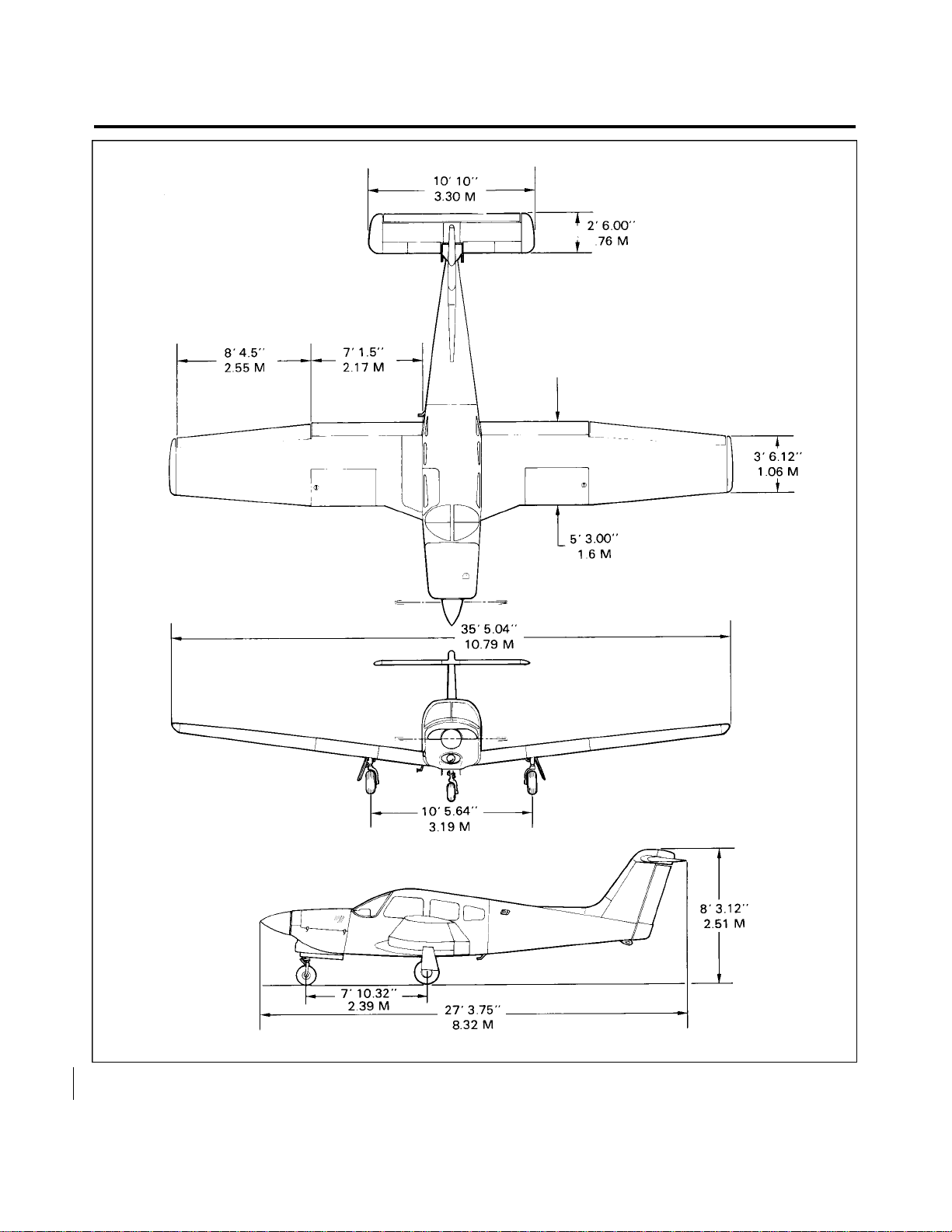
PIPER AIRCRAFT
PA-28RT-201 / 201T
* MAINTENANCE MANUAL
Figure 6-1. Three View of PA-28RT-201T
1B22
6-10-00
Page 6-05
Revised: August 17, 1982
Page 47
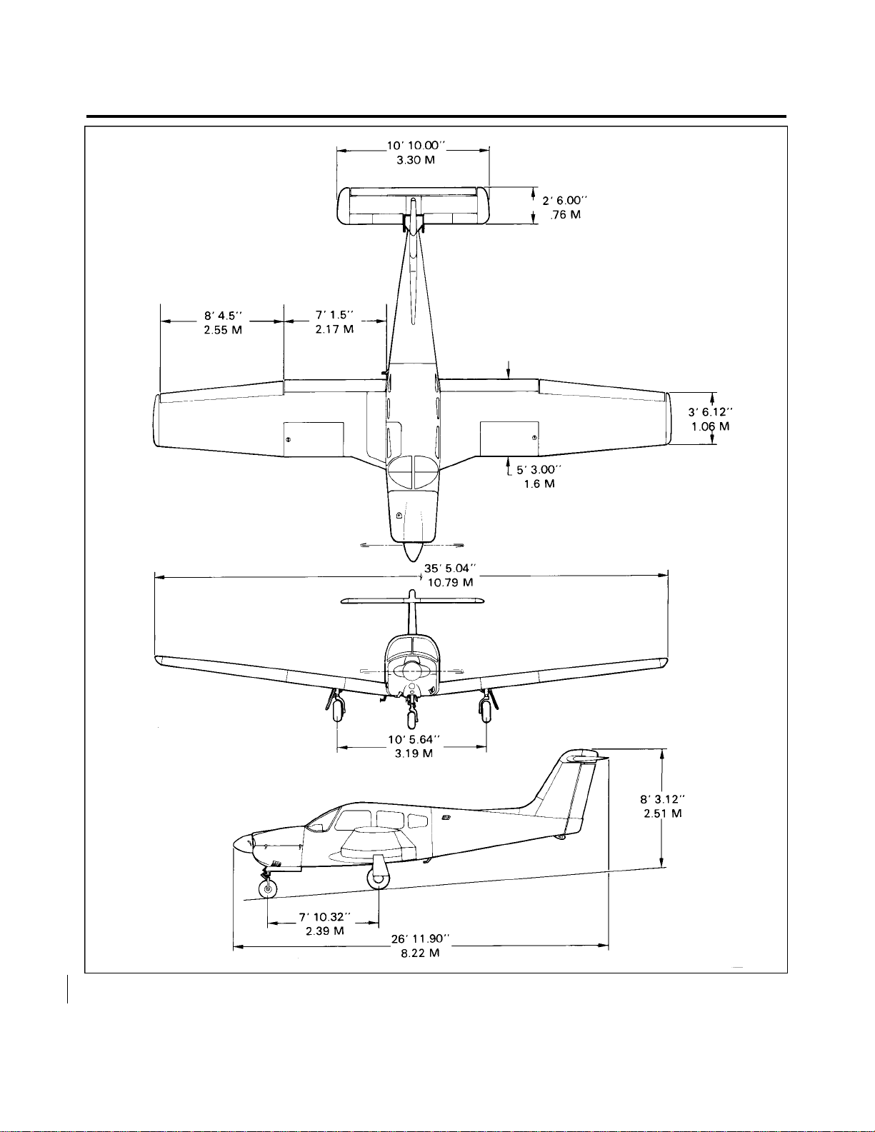
PIPER AIRCRAFT
PA-28RT-201 / 201T
* MAINTENANCE MANUAL
Figure 6-2. Three View of PA-28RT-201
1B23
6-10-00
Page 6-06
Revised: August 17, 1982
Page 48

PIPER AIRCRAFT
PA-28RT-201 / 201T
* MAINTENANCE MANUAL
STATION REFERENCE LINES.
In order to facilitate the location of various components of the airplane which require maintenance and
servicing, a method utilizing fuselage station (Sta.) wing station or buttock line (BL), and water line (WL)
designations is frequently employed in this manual. (Refer to Figure 6-3.) Fuselage stations, buttock and water
lines are reference points measured by inches in the vertical or horizontal direction from a given reference line
which indicates station locations of structural members of the airplane. Station O of the fuselage is 44.5 inches
ahead of the lower edge of the firewall; station O (BL) of the wing and stabilator is the centerline of the
airplane; and station O (WL) of the fuselage vertical stabilizer and rudder is 20.5 inches below the cabin floor
as measured at the rear wing spar with the airplane level.
THIS SPACE INTENTIONALLY LEFT BLANK
1B24
6-20-00
Page 6-07
December 1, 1978
Page 49
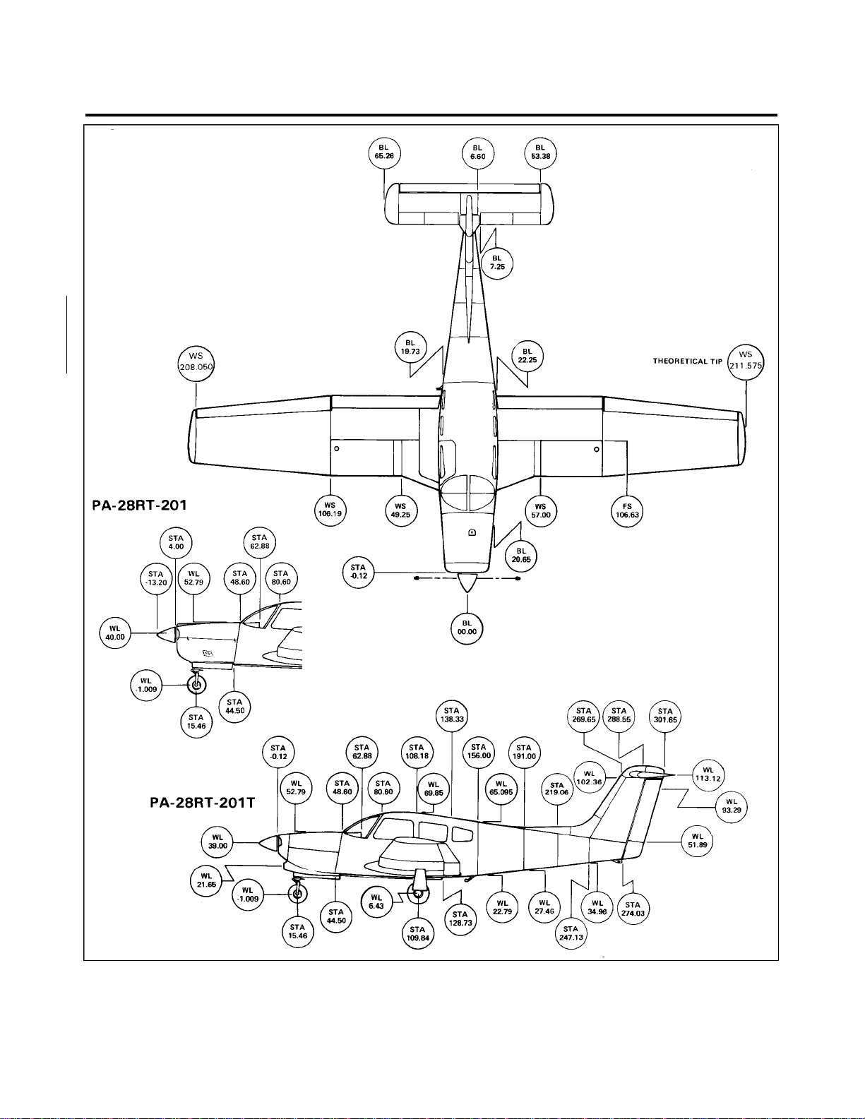
PIPER AIRCRAFT
PA-28RT-201 / 201T
* MAINTENANCE MANUAL
Figure 6-3. Station Reference Lines of PA-28RT-201/201T
1C1
6-20-00
Page 6-08
Revised: July 13, 1983
Page 50

PIPER AIRCRAFT
PA-28RT-201 / 201T
* MAINTENANCE MANUAL
ACCESS AND INSPECTION PROVISIONS.
The access and inspection provisions for the airplane are shown in Figure 6-4. The component to be
serviced or inspected through each opening is identified in the illustration. All access plates and panels are
secured by either metal fasteners or screws. To enter the aft section of the fuselage, open the baggage
compartment door and remove the access panel.
—CAUTION—
Before entering the aft section of the fuselage, be sure the
airplane is supported at the tail skid.
WEIGHT AND BALANCE DATA.
When figuring various weight and balance computations, the empty, static and gross weight, and center of
gravity of the airplane may be found in the Weight and Balance Form of the Airplane Flight Manual.
SERIAL NUMBER PLATE.
The serial number plate is located on the left side of the fuselage near the leading edge of the stabilator.
The serial number should always be used when referring to the airplane on service or warranty matters.
1C2
6-50-00
Page 6-09
December 1, 1978
Page 51
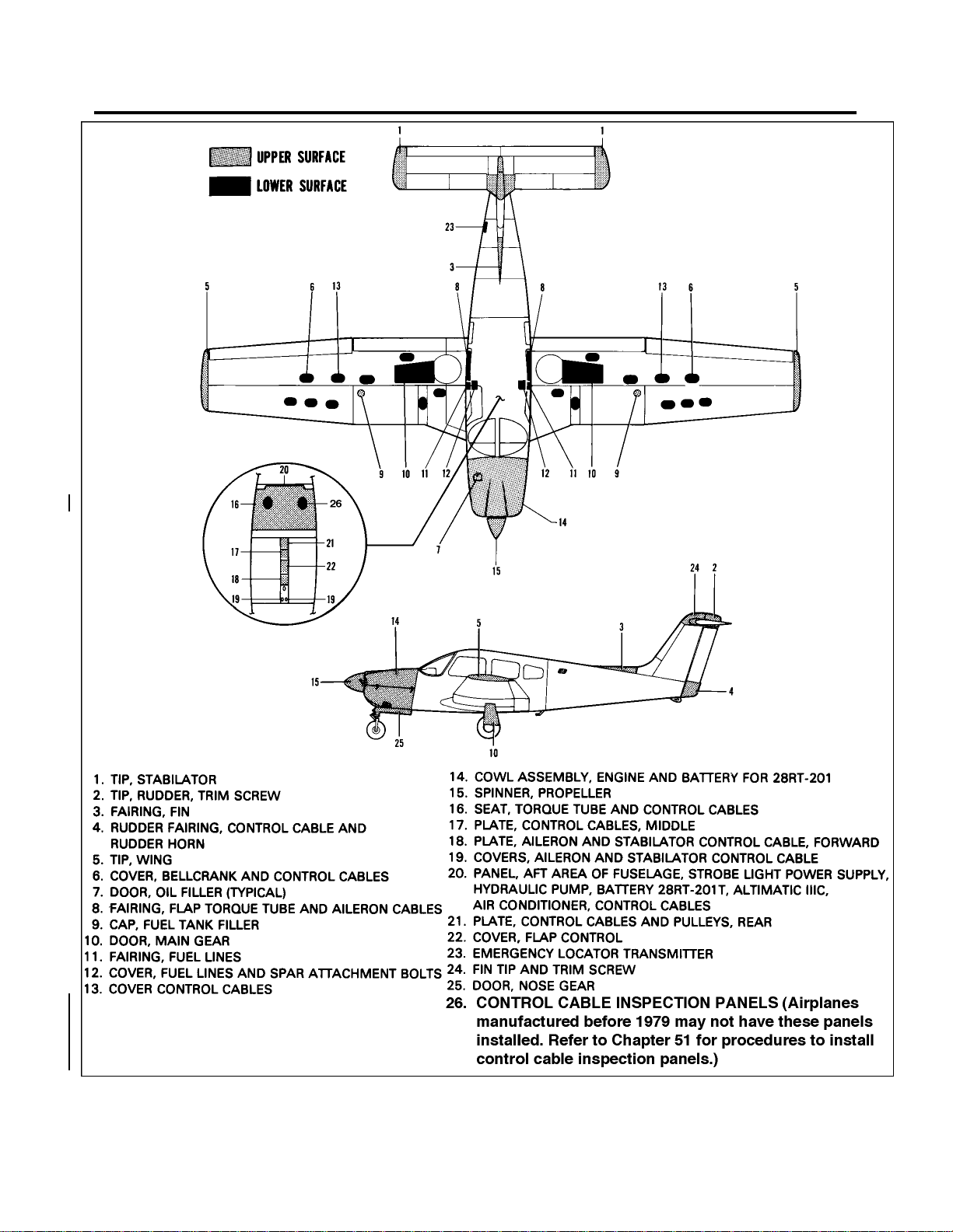
PIPER AIRCRAFT
PA-28RT-201 / 201T
* MAINTENANCE MANUAL
Figure 6-4. Access Plates and Panels
1C3
6-50-00
Page 6-10
Interim Revision: February 27, 1995
Page 52

PIPER AIRCRAFT
PA-28RT-201 / 201T
* MAINTENANCE MANUAL
THIS PAGE INTENTIONALLY LEFT BLANK
1C4
Page 53

CHAPTER
LIFTING AND SHORING
1C5
Page 54

PIPER AIRCRAFT
PA-28RT-201 / 201T
MAINTENANCE MANUAL
CHAPTER 7- LIFTING AND SHORING
TABLE OF CONTENTS/EFFECTIVITY
CHAPTER
SECTION GRID
SUBJECT SUBJECT NO. EFFECTIVITY
7-10-01 JACKING 1C7
1C6
7- Cont./Effec.
Page - 1
Revised: February 23, 1979
Page 55
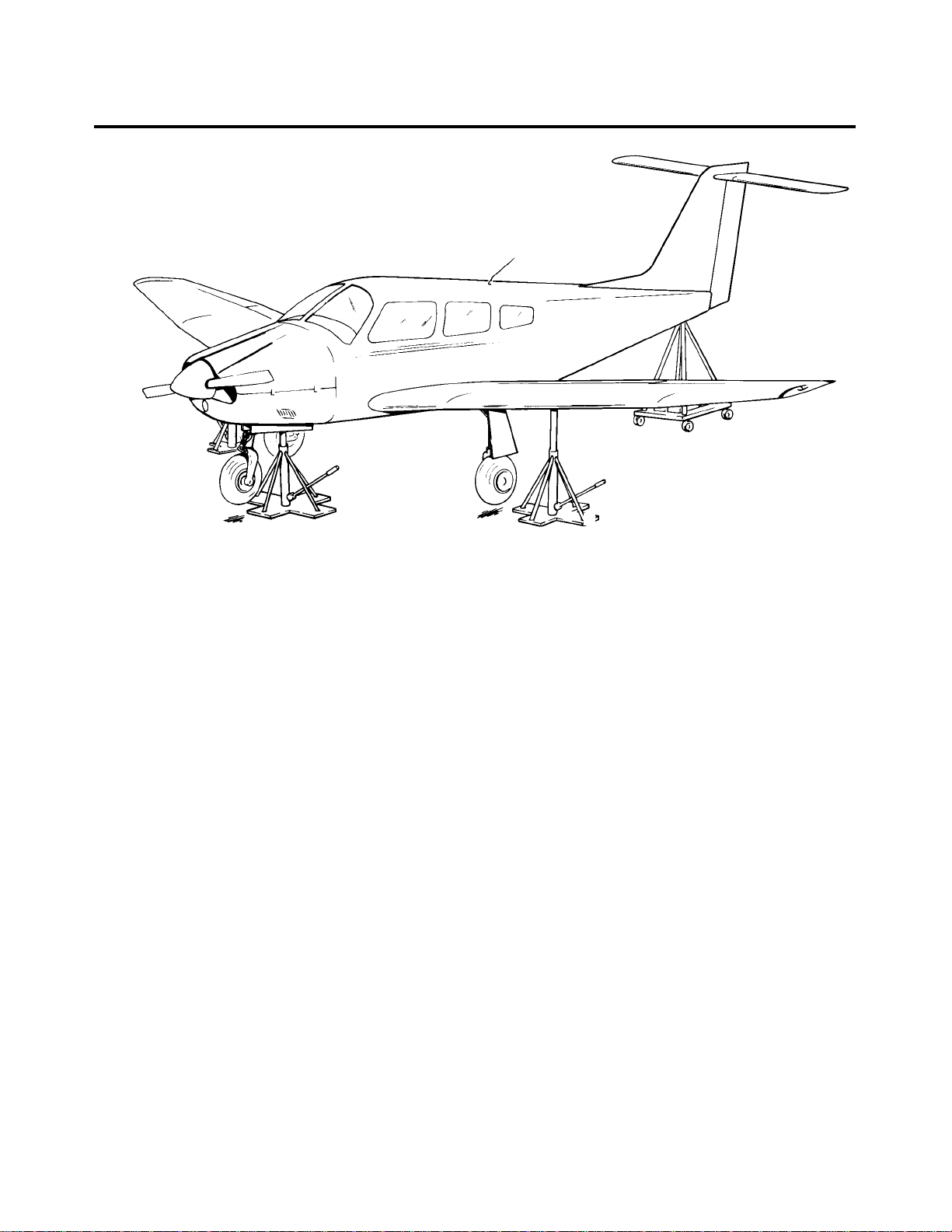
PIPER AIRCRAFT
PA-28RT-201 / 201T
MAINTENANCE MANUAL
Figure 7-1. Jacking Arrangement
JACKING.
Jacking the airplane is necessary to service the landing gear and to perform other service operations.
Proceed as follows:
1. Place jacks under jack pads on the front wing spar. (Refer to Figure 7-1.)
—NOTE—
A jacking point on the airplane is also provided on the underside
of the fuselage directly behind the nose gear actuating cylinder.
This may be used along with the wing jack points to raise the
airplane, or alone it may be used to raise the front end.
2. Attach the tail support to the tail skid. Place approximately 250 pounds of ballast on the base of the tail
support to hold down the tail.
—CAUTION—
Be sure to apply sufficient tail support ballast; otherwise the
airplane will tip forward.
3. Raise the jacks until all three wheels are clear of the surface.
—END—
1C7
7-10-01
Page 7-01
December 1, 1978
Page 56

PIPER AIRCRAFT
PA-28RT-201 / 201T
MAINTENANCE MANUAL
THIS PAGE INTENTIONALLY LEFT BLANK
1C8
Page 57

CHAPTER
LEVELING AND WEIGHING
1C9
Page 58

PIPER AIRCRAFT
PA-28RT-201 / 201T
MAINTENANCE MANUAL
CHAPTER 8- LEVELING AND WEIGHING
TABLE OF CONTENTS/EFFECTIVITY
CHAPTER
SECTION GRID
SUBJECT SUBJECT NO. EFFECTIVITY
8-10-01 LEVELING 1C11
8-20-01 WEIGHING 1C11
1C10
8 - Cont./Effec.
Page - 1
Revised: February 23, 1979
Page 59

PIPER AIRCRAFT
PA-28RT-201 / 201T
* MAINTENANCE MANUAL
LEVELING.
The airplanes are provided with a means for longitudinal and lateral leveling. The airplanes may be leveled
while on jacks, during the weighing procedure while the wheels are on scales, or while the wheels are on the
ground. To level the airplane for purposes of weighing or rigging, the following procedures may be used:
1. To longitudinally level the airplane, partially withdraw the two leveling screws located immediately
below the left front side window. (Refer to Figure 8-1.) Place a level on these screw heads and adjust the jacks
until the level is centered. Should the airplane be either on scales or on the floor, first block the main gear oleos
to full extension; then deflate the nose wheel until the proper position is reached.
2. To laterally level the airplane, place a level across the spar box assembly located under the rear seat.
(Refer to Figure 8-2.) Raise or lower one wing tip by deflating the appropriate tire on the high side of the
airplane or adjust either jack until the bubble of the level is centered.
WEIGHING. (Refer to Figure 8-3.)
The airplane may be weighed by the following procedure:
1. Position a scale and ramp in front of each of the three wheels.
2. Secure the scales from rolling forward and tow the airplane up onto the scales.
3. Remove the ramp so as not to interfere with the scales.
4. If the airplane is to be weighed for weight and balance computations, level the airplane per instructions
given in Paragraph titled Leveling.
—END—
1C11
8-20-01
Page 8-01
December 1, 1978
Page 60
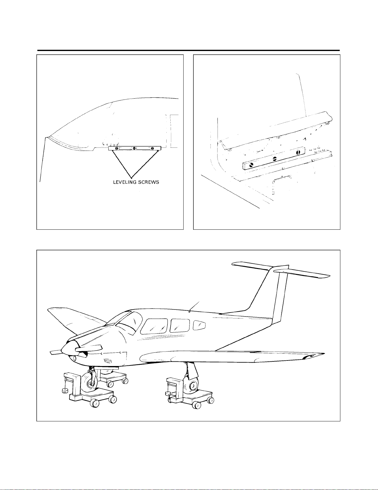
PIPER AIRCRAFT
PA-28RT-201 / 201T
* MAINTENANCE MANUAL
Figure 8-1. Leveling Longitudinally Figure 8-2. Leveling Laterally
Figure 8-3. Weighing Arrangement
1C12
8-20-01
Page 8-02
Revised: July 13, 1983
Page 61

PIPER AIRCRAFT
PA-28RT-201 / 201T
MAINTENANCE MANUAL
THIS PAGE INTENTIONALLY LEFT BLANK
1C13
Page 62

CHAPTER
TOWING AND TAXIING
1C14
Page 63

PIPER AIRCRAFT
PA-28RT-201 / 201T
MAINTENANCE MANUAL
CHAPTER 9 - TOWING AND TAXIING
TABLE OF CONTENTS/EFFECTIVITY
CHAPTER
SECTION GRID
SUBJECT SUBJECT NO. EFFECTIVITY
9-10-01 TOWING 1C16
9-20-01 TAXIING 1C16
1C15
9 - Cont./Effec.
Page - 1
Revised: February 23, 1979
Page 64

PIPER AIRCRAFT
PA-28RT-201 / 201T
*MAINTENANCE MANUAL
TOWING.
The airplane may be moved by using the nose wheel steering bar that is stowed in the baggage area or
power equipment that will not damage or cause excess strain to the nose gear steering assembly. The stem on
the bar is inserted in the hollow of the nose wheel axle at its right side.
—CAUTION—
When towing with power equipment, do not turn the nose gear in
either direction beyond its steering radius limits as this will result
in damage to the nose gear and steering mechanism.
In the event towing lines are necessary, lines (rope) should be attached to both main gear struts as high up
on the tubes as possible. Lines should be long enough to clear the nose and/or tail by not less than 15 feet, and
a qualified person to ride in the pilot’s seat to maintain control by use of the brakes.
TAXIING.
Before attempting to taxi the airplane, ground personnel should be checked out by a qualified pilot or other
responsible person. Engine starting and shut-down procedures should be covered as well. When it is
ascertained that the propeller back blast and taxi areas are clear, apply power to start the taxi roll and perform
the following checks:
1. Taxi forward a few feet and apply brakes to determine their effectiveness.
2. Taxi with propeller set in low pitch, high RPM setting.
3. While taxiing, make slight turns to ascertain the effectiveness of steering.
4. Observe wing clearances when taxiing near buildings or other stationary objects. If possible, station a
guide outside the airplane to observe.
5. When taxiing on uneven ground, avoid holes and ruts.
6. Do not operate the engine at high RPM when running up or taxiing over ground containing loose
stones, gravel or any loose material that may cause damage to the propeller blades.
—END—
1C16
9-20-01
Page 9-01
December 1, 1978
Page 65

PIPER AIRCRAFT
PA-28RT-201 / 201T
MAINTENANCE MANUAL
THIS PAGE INTENTIONALLY LEFT BLANK
1C17
Page 66

CHAPTER
PARKING AND MOORING
1C18
Page 67

PIPER AIRCRAFT
PA-28RT-201 / 201T
MAINTENANCE MANUAL
CHAPTER 10 - PARKING AND MOORING
TABLE OF CONTENTS/EFFECTIVITY
CHAPTER
SECTION GRID
SUBJECT SUBJECT NO. EFFECTIVITY
10-10-01 PARKING 1C20
10-20-01 MOORING 1C20
10-20-02 Locking Airplane 1C20
1C19
10- Cont./Effec.
Page- 1
Revised: February 23, 1979
Page 68

PIPER AIRCRAFT
PA-28RT-201 / 201T
*MAINTENANCE MANUAL
PARKING.
When parking the airplane, insure that it is sufficiently protected against adverse weather conditions and
presents no danger to other aircraft. When parking the airplane for any length of time or overnight, it is
recommended that it be moored.
1. To park the airplane, head it into the wind, if possible.
2. Set the parking brake by pulling back the brake lever and depressing the knob attached to the left side
of the handle, then release the handle. To release the parking brake, pull back on the brake lever to disengage
the catch mechanism, and allow the handle to swing forward.
—NOTE—
Care should be taken when setting brakes that are overheated or
during cold weather when accumulated moisture may freeze the
brakes.
3. The aileron and stabilator may be locked by using the front seat belt.
MOORING.
The airplane is moored to insure its immovability, protection and security under various weather
conditions. In order to properly moor the airplane use the following procedures:
1. Head the airplane into the wind, if possible.
2. Block the wheels.
3. Lock the aileron and stabilator controls using the front seat belt.
4. Secure tie-down ropes to the wing tie-down rings and the tail skid at approximately 45 degree angles
to the ground. When using rope constructed of non-synthetic material, leave sufficient slack to avoid damage
to the airplane when the ropes contract due to moisture.
—CAUTION—
Use square or bowline knots. Do not use slip knots.
—NOTE—
Additional preparations for high winds include using tie-down
ropes from the landing gear forks, and securing the rudder.
5. Install pitot tube cover, if available.
LOCKING AIRPLANE.
The cabin and baggage compartment doors are provided with a key lock on the outside. The ignition
switch and cabin door require the same key while the baggage compartment door has a separate key.
—END—
1C20
10 - 20 - 02
Page - 10-01
December 1, 1978
Page 69

PIPER AIRCRAFT
PA-28RT-201 / 201T
MAINTENANCE MANUAL
THIS PAGE INTENTIONALLY LEFT BLANK
1C21
Page 70

CHAPTER
REQUIRED PLACARDS
1C22
Page 71

PIPER AIRCRAFT
PA-28RT-201 / 201T
MAINTENANCE MANUAL
CHAPTER 11- REQUIRED PLACARDS
TABLE OF CONTENTS/EFFECTIVITY
CHAPTER
SECTION GRID
SUBJECT SUBJECT NO. EFFECTIVITY
11-20-00 EXTERIOR PLACARDS AND MARKINGS 1C24 2R 7-81
11-30-00 INTERIOR PLACARDS AND MARKINGS 1D1
1C23
11 - Cont./Effec.
Page - 1
Revised: February 23, 1979
Page 72
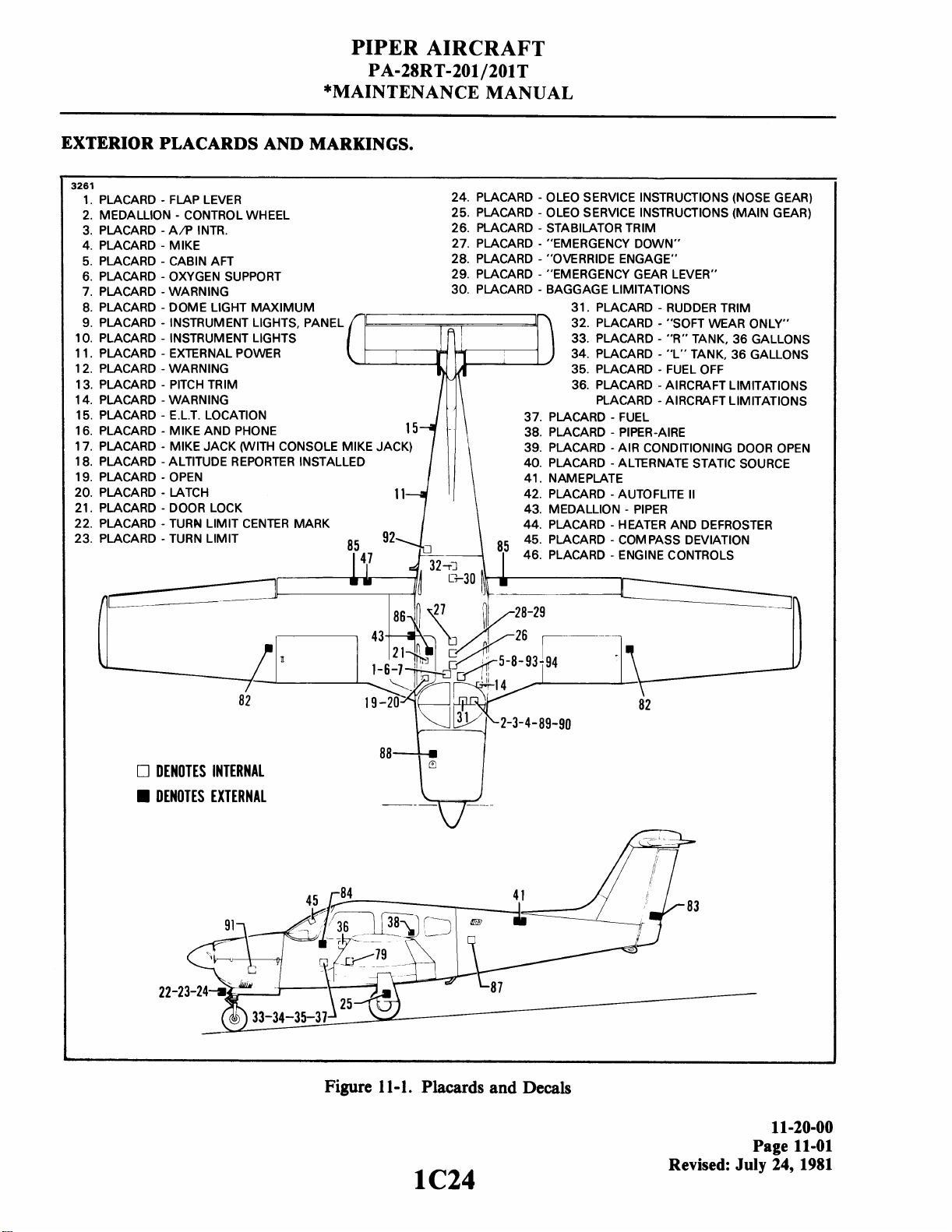
PIPER AIRCRAFT
PA-28RT-201/201T
*MAINTENANCE MANUAL
EXTERIOR PLACARDS AND MARKINGS.
3261
1. PLACARD - FLAP LEVER
2. MEDALLION
3. PLACARD
4. PLACARD - MIKE
5. PLACARD
6. PLACARD
7.
PLACARD - WARNING
8. PLACARD
9. PLACARD - INSTRUMENT LIGHTS, PANEL 32. PLACARD - "SOFT WEAR ONLY"
10. PLACARD
1 1. PLACARD
12. PLACARD
1 3. PLACARD
14. PLACARD - WARNING PLACARD - AIRCRAFT LIMITATIONS
15. PLACARD
16. PLACARD
17. PLACARD
18. PLACARD
19. PLACARD
20. PLACARD
21. PLACARD - DOOR LOCK
22. PLACARD
23. PLACARD
-
CONTROL WHEEL
-
A/P INTR.
-
CABIN AFT
-
OXYGEN SUPPORT
-
DOME LIGHT MAXIMUM
-
INSTRUMENT LIGHTS 33. PLACARD - "R" TANK, 36 GALLONS
-
EXTERNAL POWER
-
WARNING 35. PLACARD - FUEL OFF
-
PITCH TRIM
-
E.L.T. LOCATION
-
MIKE AND PHONE
-
MIKE JACK (WITH CONSOLE MIKE JACK)
-
ALTITUDE REPORTER INSTALLED
-
OPEN
-
LATCH
-
TURN LIMIT CENTER MARK
-
TURN LIMIT
24. PLACARD
25. PLACARD
26. PLACARD
27. PLACARD
28. PLACARD
29. PLACARD
30. PLACARD
-
OLEO SERVICE INSTRUCTIONS (NOSE GEAR)
-
OLEO SERVICE INSTRUCTIONS (MAIN GEAR)
-
STABllATOR TRIM
-
"EMERGENCY DOWN"
-
"OVERRIDE ENGAGE"
-
"EMERGENCY GEAR LEVER"
-
BAGGAGE LIMITATIONS
-
31. PLACARD
34. PLACARD
36. PLACARD - AIRCRAFTLIMITATIONS
-
37. PLACARD
38. PLACARD
39. PLACARD
PLACARD
40.
41. NAMEPLATE
42. PLACARD
43. MEDALLION
PLACARD
44.
45. PLACARD - COMPASS DEVIATION
5
46. PLACARD
FUEL
-
PIPER-AIRE
-
AIR CONDITIONING DOOR OPEN
-
ALTERNATE STATIC SOURCE
-
AUTOFLITE
-
HEATER AND DEFROSTER
-
ENGINE CONTROLS
RUDDER TRIM
-
"L" TANK, 36 GALLONS
-
PIPER
II
DENOTES INTERNAL
DENOTES EXTERNAL
_I
Figure
1 1
-
1. Placards and Decals
11-20-00
Page
11-01
Revised:
July
24,
1981
Page 73
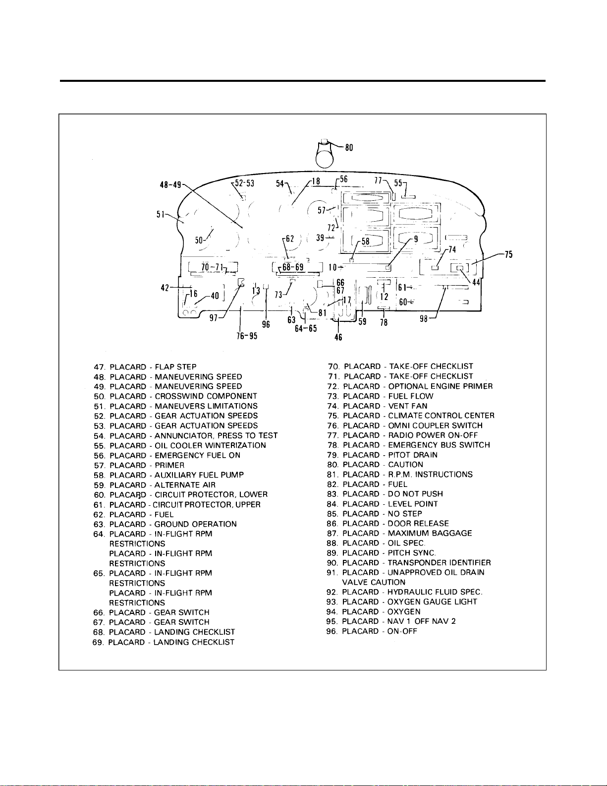
PIPER AIRCRAFT
PA-28RT-201 / 201T
MAINTENANCE MANUAL
INTERIOR PLACARDS AND MARKINGS.
Figure 11-1. Placards and Decals (cont)
1D1
11-30-00
Page 11-02
Revised: February 23, 1979
Page 74

PIPER AIRCRAFT
PA-28RT-201 / 201T
MAINTENANCE MANUAL
THIS PAGE INTENTIONALLY LEFT BLANK
1D2
Page 75

PIPER AIRCRAFT
PA-28RT-201 / 201T
MAINTENANCE MANUAL
THIS PAGE INTENTIONALLY LEFT BLANK
1D3
Page 76

PIPER AIRCRAFT
PA-28RT-201 / 201T
MAINTENANCE MANUAL
THIS PAGE INTENTIONALLY LEFT BLANK
1D4
Page 77

CHAPTER
SERVICING
1D5
Page 78

PIPER AIRCRAFT
PA-28RT-201 / 201T
*MAINTENANCE MANUAL
CHAPTER 12 - SERVICING
TABLE OF CONTENTS/EFFECTIVITY
CHAPTER
SECTION GRID
SUBJECT SUBJECT NO. EFFECTIVITY
12-00-00 GENERAL 1D8 2-79
12-10-01 REPLENISHING 1D10
12-10-02 Fuel System 1D10 2-79
12-10-03 Filling Fuel Tanks 1D10
12-10-04 Fuel Anti-Icing Additive 1D10 A 11-79
12-10-05 Draining Moisture From Fuel System 1D11 7-81
12-10-06 Draining Fuel System 1D11
12-10-07 Servicing Oil System 1D11
12-10-08 Filling Oil Sump 1D12
12-10-09 Draining Oil Sump 1D12
12-10-10 Oil Filter (Full Flow) 1D12 2R 7-83
12-10-11 Recommendations for Changing Oil 1D13
12-10-12 Winterization Plate 1D13
12-20-01 SCHEDULED SERVICING 1D14
12-20-02 Landing Gear 1D14
12-20-03 Oleo Struts 1D14
12-20-04 Filling Oleo Struts 1D15 12-81
12-20-05 Inflating Oleo Struts 1D16
12-20-06 Brake System 1D16
12-20-07 Filling Brake Cylinder Reservoir 1D16
12-20-08 Draining Brake System 1D16
12-20-09 Tires 1D16
12-20-10 Tire Balance 1D17
12-20-11 Hydraulic System 1D17
12-20-12 Servicing Hydraulic Pump/Reservoir 1D18 12-81
12-20-13 Electrical System 1D18
12-20-14 Battery 1D18 2-79
12-20-15 Induction Air Filter 1D18
12-20-16 Removal of Air Filter 1D18
12-20-17 Service Instructions (Cleaning and Inspection) 1D19
12-20-18 Installation of Air Filter 1D19
12-20-19 Alternate Air Door 1D19
12-20-20 Power Plant 1D20
12-20-21 Propeller 1D20
12-20-22 Cleaning 1D20
12-20-23 Engine Compartment 1D20
1D6
12 - Cont./Effec.
Page- 1
Revised: July 13, 1983
Page 79

PIPER AIRCRAFT
PA-28RT-201 / 201T
*MAINTENANCE MANUAL
CHAPTER 12- SERVICING (cont)
TABLE OF CONTENTS/EFFECTIVITY
CHAPTER
SECTION GRID
SUBJECT SUBJECT NO. EFFECTIVITY
12-20-01 SCHEDULED SERVICING (cont) —
12-20-24 Landing Gear 1D21
12-20-25 Exterior Surfaces 1D21
12-20-26 Windshield and Windows 1D21
12-20-27 Headliner, Side Panels and Seats 1D22
12-20-28 Carpets 1D22
12-20-29 Lubrication Instructions 1D22
12-20-30 Application of Oil 1D22
12-20-31 Application of Grease 1D23
12-20-32 Lubrication Charts 1D23 2R 7-81
1D7
12- Cont./Effec.
Page - 2
Revised: February 23, 1979
Page 80
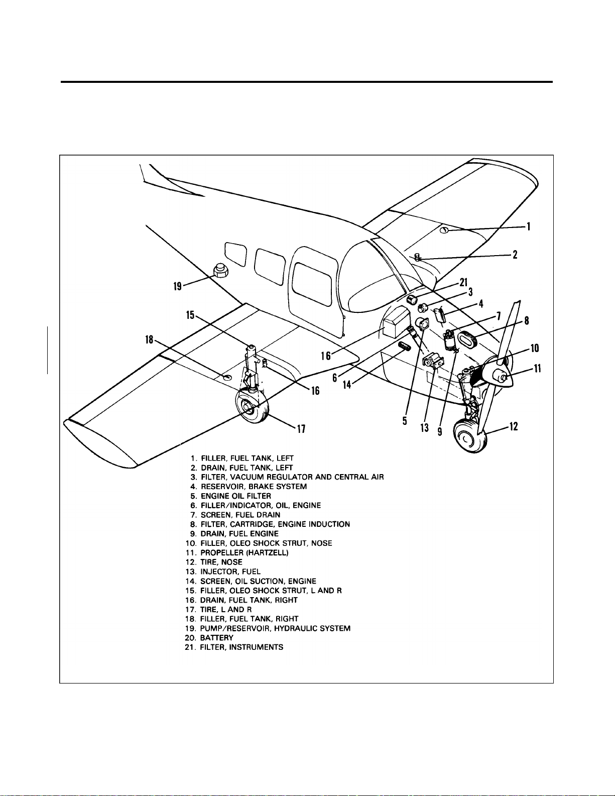
PIPER AIRCRAFT
PA-28RT-201 / 201T
*MAINTENANCE MANUAL
GENERAL.
Servicing the airplane includes the replenishment of fuel, oil, hydraulic fluid, tire pressures, lubrication
requirements and other required items.
Figure 12-1. Servicing Points (PA-28RT-201)
1D8
12-00-00
Page 12-01
Revised: February 23, 1979
Page 81
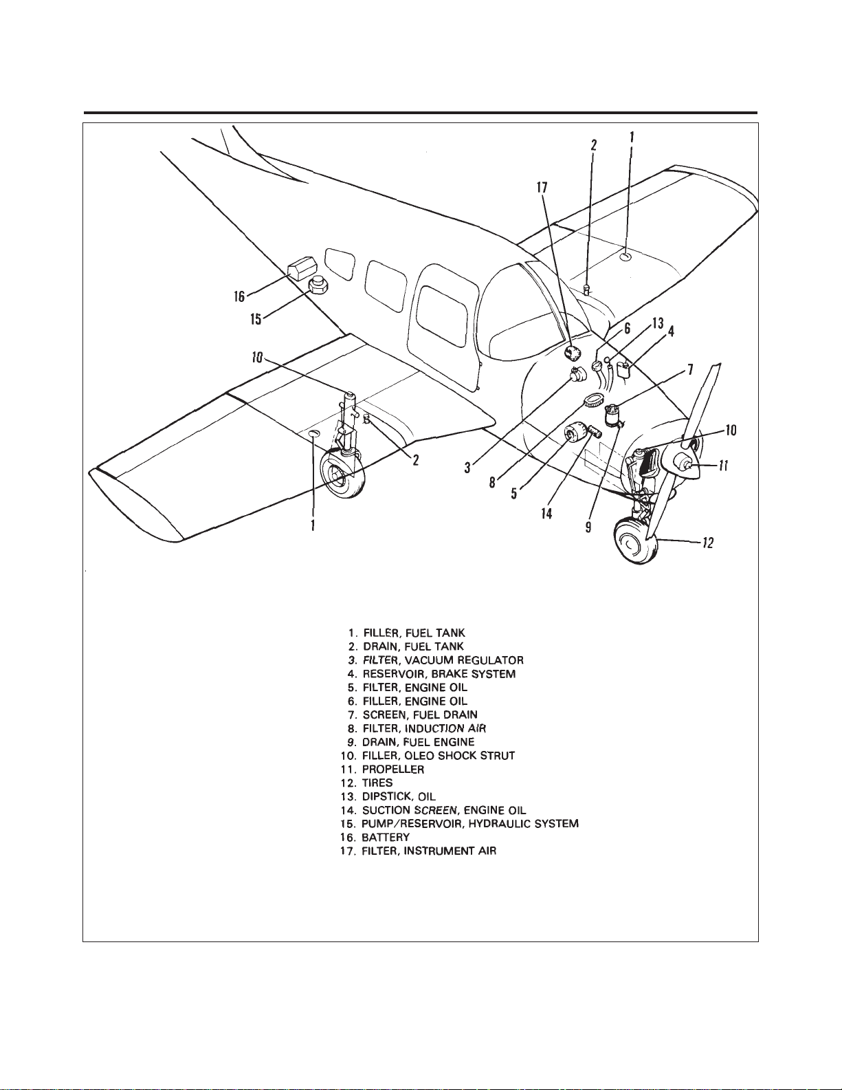
PIPER AIRCRAFT
PA-28RT-201 / 201T
*MAINTENANCE MANUAL
Figure 12-2. Servicing Points (PA-28RT-201T)
1D9
12-00-00
Page 12-02
December 1, 1978
Page 82
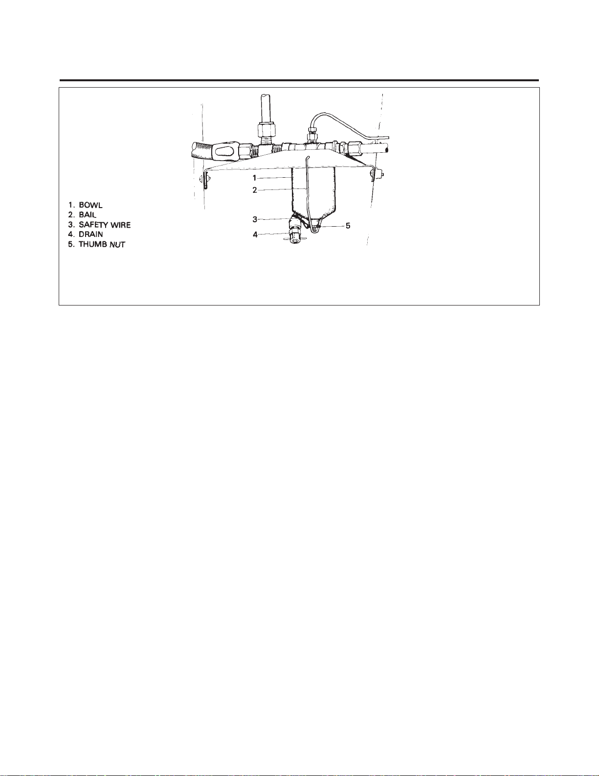
PIPER AIRCRAFT
PA-28RT-201 / 201T
*MAINTENANCE MANUAL
Figure 12-3. Fuel Strainer
REPLENISHING.
FUEL SYSTEM.
At intervals of 50-hours or 90 days, whichever comes first, clean the fuel strainer screen, located in the
fuel bowl mounted on the lower left side of the firewall, and clean the screen in the inlet side of the injector.
Remove and clean the fuel strainer screen in accordance with the instructions outlined in Chapter 28.
Additional fuel system service information may also be found in Chapter 28. Inspection intervals of the
various fuel system components may be found in Chapter 5.
FILLING FUEL TANKS.
Observe all required precautions for handling gasoline. Fill the fuel tanks with the fuel as specified on the
placard adjacent to the filler neck. Each wing tank has a capacity of 38-1/2 U.S. gallons, for a total capacity of
77 U.S. gallons. Five U.S. gallons are considered unusable fuel.
FUEL ANTI-ICING ADDITIVE.
This aircraft is approved for operation with a fuel anti-icing additive. The anti-icing additive used must
meet specification MIL-1-27686 and must be uniformly blended with the fuel while refueling. The additive
must not exceed .15% by volume of the refueled quantity and to ensure its effectiveness should be blended at
not less than .10% by volume (approximately 1 1/2 liquid ozs. per ten gallons of fuel). A blender supplied by
the additive manufacturer should be used. Except for the information contained in this section, the
manufacturer’s mixing or blending instructions should be carefully followed.
1D10
12-10-04
Page 12-03
Revised: November 6, 1979
Page 83

PIPER AIRCRAFT
PA-28RT-201 / 201T
*MAINTENANCE MANUAL
—CAUTION—
Assure that the additive is directed into the flowing fuel stream.
The additive flow should start after and stop before the fuel flow.
Do not permit the concentrated additive to come in contact with
the aircraft painted surfaces or the interior surfaces of the fuel
tanks.
Some fuels have anti-icing additives pre-blended in the fuel at the
refinery so no further blending should be performed.
Fuel additive cannot be used as a substitute for preflight draining
of the fuel system drains.
DRAINING MOISTURE FROM FUEL SYSTEM.
The fuel tanks and fuel strainer should be drained daily prior to first flight and after refueling to avoid the
accumulation of water or sediment. Each fuel tank is equipped with an individual quick drain located at the
lower inboard rear corner of the tank. The fuel strainer with a quick drain valve (refer to Figure 12-3) is
located on the lower left side of the firewall. Drain fuel tanks and strainer per the following:
1. Drain each tank through its individual quick drain located at the lower inboard rear corner of the tank,
making sure that enough fuel has been drained to insure that all water and sediment is removed.
2. Place a container under the fuel strainer drain. Drain the fuel strainer by opening the quick drain on the
strainer.
3. Examine the contents of the container placed under the fuel strainer drain for water and sediment and
dispose of the contents.
—CAUTION—
When draining any amount of fuel, care should be taken to
insure that no fire hazard exists before starting engine.
DRAINING FUEL SYSTEM.
Fuel may be drained from the system by opening the valve at the inboard end of each fuel tank. The drain
valve requires the drain cup pin to hold valve open. The remaining fuel in the system may be drained through
the filter bowl. Any individual tank may be drained by closing the selector valve and then draining as desired.
SERVICING OIL SYSTEM.
The engine oil level should be checked before each flight and changed after each 100 hours of engine
operation. During oil change the oil screen(s) should be removed and cleaned, and the oil filter cartridge
replaced. Replace oil filter at 50-hour intervals. Use a quality brand aviation grade oil of the proper season
viscosity. For information on the use of detergent oil, on the PA-28RT-201 airplanes refer to Application of Oil
and/or latest revision Lycoming Service Instruction Letter 1014. Detergent oil that meets Continental Motors
Corporation Specification MHS-24, is the only recommended lubricating oil for the PA-28RT-201T airplanes.
1D11
12-10-07
Page 12-04
Revised: July 24, 1981
Page 84

PIPER AIRCRAFT
PA-28RT-201 / 201T
*MAINTENANCE MANUAL
—CAUTION—
Do not introduce any trade additive to the basic lubricant unless
recommended by the engine manufacturer.
FILLING OIL SUMP.
The oil sump should normally be filled with oil to the mark on the engine dipstick. The quantity of oil
required for the engines may be found in Chapter 6. The specified grade of oil may be found in the Lubrication
Chart, or on the access door. To service the engine with oil, open the access door and remove the oil filler cap.
DRAINING OIL SUMP.
To drain the oil sump, provide a suitable container with a minimum capacity of that required to fill the
sump. Remove the engine cowl and on PA-28 RT-201 airplanes open the oil drain valve by pushing the center
of the drain up and turning counterclockwise. This will hold the drain in the open position. On PA-28RT-201T
airplanes remove the fuel drain probe from the clip on the right rear engine baffle. Install suitable hose on
probe and insert in quick drain valve located on the underside of the engine. It is recommended the engine be
warmed to operating temperature to insure complete draining of the old oil.
OIL FILTER. (Full Flow)
1. The oil filter element should be replaced after each 50-hours of engine operation; this is accomplished
by removing the lockwire from the bolthead at the end of the filter, loosening the bolt, and removing the filter
assembly from the adapter.
2. Before discarding the filter element, remove the outer perforated paper cover, and using a sharp knife,
cut through the folds of the element at both ends, close to the metal caps. Then, carefully unfold the pleated
element and examine the material trapped in the filter for evidence of internal engine damage such as chips or
particles from bearings. In new or newly overhauled engines, some small particle of metallic shavings might
be found; these are generally of no consequence and should not be confused with particles produced by
impacting, abrasion or pressure. Evidence of internal engine damage found in the oil filter justifies further
examination to determine the cause.
3. On Continental engines proceed as follows:
—NOTE—
Ascertain that oil filter complies with specifications of the latest
revision of Continental Aircraft Engine Service Bulletin M75-7.
A. Before installing the new filter, lubricate the gasket on the filter with engine oil, then install.
Tighten slightly more than hand tight or 3/4 to 1 full turn after gasket makes contact. Do not over
torque.
B. Run the engine and check for oil leaks; then install lockwire between nut on filter and oil filter
adapter assembly.
1D12
12-10-10
Page 12-05
Revised: July 13, 1983
Page 85

PIPER AIRCRAFT
PA-28RT-201 / 201T
*MAINTENANCE MANUAL
4. On Lycoming engines proceed as follows:
A. After the element has been replaced, tighten the attaching bolt 15 to 18 foot-pounds of torque.
B. Lockwire the bolt through the loops on the side of the housing to the drilled head of the
thermostatic valve. Be sure the lockwire is replaced at both the attaching bolthead and the
thermostatic oil cooler bypass valve.
RECOMMENDATIONS FOR CHANGING OIL.
The engine manufacturer recommends that the oil supply be drained and the entire sump filled with fresh
oil after each 100-hours of engine operation. Always start and warm the engine to operating temperature
before performing an oil change. While draining the oil, the screens should be removed from the crankcase
cover and cleaned thoroughly. If sludge deposits are heavy, subsequent oil changes should be made at shorter
intervals.
1. Note the following for Continental engines:
A. D e t e rgent oil that meets Continental Motors Corporation Specification MHS-24, is the only
recommended lubricating oil.
B. Use SAE-30 or 10W-30 below 40° F and SAE-50 above 40° F. When the average ambient air
temperature is approximately at the dividing line, use the lighter oil.
2. Note the following for Lycoming engine.
A. N o n - d e t e rgent oil that meets MIL-L-6082 specification is recommended by Lycoming. (See
Lubrication Chart.)
B. For use of detergent oil note the following: Also refer to the latest revision of Lycoming Service
Information No. 1014.
(1) In engines that have been operating on straight mineral oil for several hundred hours, a change
to additive oil should be made with a degree of caution, since the cleaning action of some
additive oils will tend to loosen sludge deposits and cause plugged oil passages. When an
engine has been operating on straight mineral oil and is known to be in excessively dirty
condition, the switch to additive or compounded oil should be deferred until after the engine is
overhauled.
(2) When changing from straight oil to compound oil, the following precautionary steps should be
taken:
(a) Do not add additive oil to straight mineral oil. Drain the straight mineral oil from the
engine and fill with additive oil.
(b) Do not operate the engine longer than five hours before the first oil change.
(c) Check all oil screens for evidence of sludge or plugging and change oil every ten
hours if sludge conditions are evident. Resume normal oil drain periods after sludge
conditions improve.
WINTERIZATION PLATE.
(PA-28RT-201 Only.) For winter operations there is a winterization plate kit available. When the ambient
temperature is 50° F or less the plate is installed on the inlet opening of the oil cooler plenum chamber. When
the plate is not being used it can be stowed on a bracket, provided for this purpose, located on the oil cooler
plenum chamber.
(PA-28RT-201T Only.) The winterization plate is mounted on the firewall when not in use (temperature is
above 50° F). The plate is mounted to the oil cooler baffle when ambient temperature is 50° F or less.
12-10-12
1D13
December 1, 1978
Page 12-06
Page 86

PIPER AIRCRAFT
PA-28RT-201 / 201T
*MAINTENANCE MANUAL
SCHEDULED SERVICING.
LANDING GEAR.
The landing gear consists of tires, brakes and oleo strut assemblies. These should be inspected for proper
gear extension, scored piston tubes, possible hydraulic fluid leakage and security and condition of all
connection points. Check the brake linings for wear and frayed edges, and brake discs for scoring. Replace if
found necessary. Checked for proper adjustment of downlock hooks, looseness of drag links and side brace
links. Minor servicing is described in the following paragraphs, and for detailed service and overhaul
instructions refer to Chapter 32.
OLEO STRUTS.
The air-oil type oleo strut should be maintained at proper strut tube exposures for best oleo action. The
nose gear strut must have approximately 2.75 inches of piston tube exposed, while the main gear strut requires
approximately 2.0 inches of tube exposure. These measurements are taken with the airplane sitting on level
surface under normal static load. (Empty weight of airplane plus full fuel and oil.) If the strut has less tube
exposure than prescribed, determine whether it needs air or oil by rocking the airplane. If the oleo strut
oscillated with short strokes (approximately one inch) and the airplane settles to its normal position within one
or two cycles after the rocking force is removed, the oleo strut requires inflating. Check the valve core and
filler plug for air leaks, correct if required, and add air as described in Inflating Oleo Struts. If the oleo strut
oscillates with long strokes (approximately three inches) and the airplane continues to oscillate after the
rocking force is removed, the oleo struts require fluid. Check the oleo for indications of oil leaks, correct if
required and add fluid as described in Filling Oleo Struts. For repair procedures of the landing gear and/or oleo
struts, refer to Chapter 32.
—WARNING—
Do not release air by removing the strut valve core or filler plug.
Depress the valve core pin until strut chamber pressure has
diminished.
—CAUTION—
Dirt and foreign particles form around the filler plugs of the
landing gear struts, therefore, before attempting to remove these
plugs, the tops of the struts should be cleaned with compressed
air and/or with a dry solvent.
1D14
12-20-03
Page 12-07
December 1, 1978
Page 87

PIPER AIRCRAFT
PA-28RT-201 / 201T
*MAINTENANCE MANUAL
FILLING OLEO STRUTS.
To fill the nose or main gear oleo strut with fluid (MIL-H-5606), whether it be the addition of a small or
large amount, proceed as follows:
1. Raise the airplane on jacks.
2. Place a pan under the gear to catch spillage.
3. At the filler plug, relieve air pressure from the strut housing chamber by removing the cap from the air
valve and depressing the valve core.
4. There are two methods by which the strut chamber may be filled and these are as follows:
Method I.
A. Remove the valve core from the filler plug at the top of the nose gear strut housing or at the top
inboard side of the main gear housing. Allow the filler plug to remain installed.
B. Attach one end of a clean plastic hose to the valve stem of the filler plug and submerge the other
end in a container of hydraulic fluid.
—NOTE—
An air-tight connection is necessary between the plastic tube and
the valve stem. Without such a connection, a small amount of air
will be sucked into the oleo strut during each sequence, resulting
in an inordinate amount of air bubbles and a prolonged filling
operation.
C. Fully compress and extend the strut thus drawing fluid from the fluid container and expelling air
from the strut chamber. By watching the fluid pass through the plastic hose, it can be determined
when the strut is full and no air is present in the chamber.
D. When air bubbles cease to flow through the hose, compress the strut fully and remove the hose
from the valve stem.
E. With the strut compressed, remove the filler plug to determine that the fluid level is visible up to
the bottom of the filler plug hole.
F. Reinstall the core in the filler plug and apply thread lubricant (Parker No. 6PB) to the threads of
the filler plug and install the plug in the top of the strut housing. Torque the plug to 45 footpounds.
Method II.
A. Remove the filler plug from the top of the nose gear strut housing or at the top inboard side of the
main gear housing.
B. Raise the strut piston tube until it is fully compressed.
C. Pour fluid from a clean container through the filler opening until it reaches the bottom of the filler
plug hole. (Air pressure type oil container may be helpful.)
D. Install the filler plug finger tight and extend and compress the strut two or three times to remove
air from the housing.
E. Remove the filler plug, raise the strut to full compression and fill with fluid if needed.
F. Apply thread lubricant (Parker No. 6PB) to the threads of the filler plug. Reinstall the filler plug
and torque to 45 foot-pounds.
1D15
12-20-04
Page 12-08
Revised: December 21, 1981
Page 88

PIPER AIRCRAFT
PA-28RT-201 / 201T
*MAINTENANCE MANUAL
5. With the airplane raised, compress and extend the gear strut several times to ascertain that the strut
actuates freely. The weight of the gear fork and wheel should extend the strut.
6. Clean off overflow of fluid and inflate the strut as described in Inflating Oleo Struts.
7. Check that fluid is not leaking around the strut piston at the bottom of the housing.
INFLATING OLEO STRUTS.
After making certain that an oleo strut has sufficient fluid, attach a strut pump to the air valve and inflate
the oleo strut. The strut should be inflated until the correct inches of piston is exposed with normal static load
(empty weight of the airplane plus full fuel and oil) on the gears. Rock the airplane several times to ascertain
that the gear settles back to the correct strut position. (If a strut pump is not available, the airplane may be
raised and line pressure from a high pressure air system used. Lower the airplane and while rocking it, let air
from the valve to bring the strut down to the proper extension. (Before capping the valve, check for valve core
leakage.)
BRAKE SYSTEM.
The brake system incorporates a hydraulic fluid reservoir through which the brake system is periodically
serviced. Fluid is drawn from the reservoir by the brake cylinders to maintain the volume of fluid required for
maximum braking efficiency. Spongy brake pedal action is often an indication that the brake fluid reservoir is
running low on fluid. Instructions for filling the reservoir are given in the next paragraph. When found
necessary to accomplish repairs to any of the brake system components, or to bleed the system, these
instructions may be found in Chapter 32.
FILLING BRAKE CYLINDER RESERVOIR.
The brake cylinder reservoir should be filled to the level marked on reservoir, with the fluid specified in
Chapter 6. The reservoir, located on the left side of the firewall in the engine compartment, should be checked
at every 50-hour inspection and replenish as necessary. No adjustment of the brakes is necessary, though they
should be checked periodically per instructions given in Chapter 32.
DRAINING BRAKE SYSTEM.
To drain the brake system, connect a hose to the bleeder fitting on the bottom of the cylinder and place the
other end of the line in a suitable container. Open the bleeder and slowly pump the hand brake lever and the
desired brake pedal until fluid ceases to flow. To clean the brake system, flush with denatured alcohol.
TIRES.
The tires should be maintained at the pressure specified in Chapter 6. When checking tire pressure,
examine the tires for wear, cuts, bruises and slippage on the wheel. The tire, tube, and wheel should be
properly balanced when installed with the index mark on the tire aligned with the index mark on the tube.
1D16
12-20-09
Page 12-09
December 1, 1978
Page 89

PIPER AIRCRAFT
PA-28RT-201 / 201T
*MAINTENANCE MANUAL
TIRE BALANCE.
Proper balancing is critical for the life of aircraft tires. If a new tire is balanced upon installation it will
usually remain balanced for the life of the tire without having any shimmy or flat spots, and an inexpensive
balancer can be made that will balance almost any tire for light aircraft. Refer to Chapter 91 for balancer
details. Balance the tire as follows:
1. Mount the tire and tube (if one is used) on the wheel, but do not install the securing bolts. Install the
wheel bearings in the wheel; then, using the -7 bushings, -6 spacers, and -5 nuts, install the wheel-tire
assembly on the -8 pipe. Secure the -5 nuts finger tight so that the wheel halves touch each other. Be sure the
bolt holes are aligned. Insert the -4 axle through the -8 pipe and place the wheel in the center of the balancer.
Make sure the axle is only on the chamfered edges of the balancer and that it is at 90° to the sides of the
balancer.
2. Release the tire. If it is out of balance it will rotate, coming to rest with the heaviest point on the
bottom. Tape a 1/2 ounce patch across top center of the tire. Rotate the tire 45° and release it again. If the tire
returns to the same position, add a 1 ounce patch and again rotate the tire and release it. Continue this
procedure until the tire is balanced.
3. When balance is attained, put a chalk mark on the sidewall directly below the patch. Use one mark for
each half ounce of weight needed. Mark the valve stem location on the tire and the opposite wheel half to
assure reassembly in the same position. Remove the wheel from the balance stand, break it down and clean the
inside of the tire with toluol. Apply a coat of patch cement to both the patch and the inside center of the tire in
line with the chalk marks. When the cement has dried, install the patches making certain they are on the
centerline of the tire and aligned with the chalk marks on the sidewall. Burnish the patches to remove trapped
air, etc.
4. When reassembling the wheel, powder the inside of the tire. Mount the tire on the valve side of the
wheel in the same position it was in when it was balanced. Install the other wheel half, aligning the chalk
marks. Install the bolts and tighten to required torque, then air the tire and recheck the balance. The wheel
should not be more than 1/2 ounce out of balance.
HYDRAULIC SYSTEM.
The general condition of the hydraulic pump and landing gear actuating cylinders should be checked.
Ensure that there are no leaks and that the line fittings are tight. The cylinder rods are to be free of all dirt and
grit. To clean the rods use an oil soaked rag and carefully wipe them. All the hydraulic lines should also be
checked for leaks, kinks, and corrosion. Check the tightness of the attachment fittings.
The gear back up extender actuator assembly is located beneath the rear seat and should be checked to
determine that it is operating properly. The diaphragm shaft may be operated by hand to make sure that it is
free to fluctuate and that the actuating arm and its components are operating freely. Check the pressure housing
assembly for cracks, breaks, or fatigue. Check to ensure that the hydraulic valve and fittings are free of leaks.
Repair and check procedures for the hydraulic pump, cylinders and various components may be found in
Chapter 29 of this manual.
12-20-11
1D17
December 1, 1978
Page 12-10
Page 90

PIPER AIRCRAFT
PA-28RT-201 / 201T
*MAINTENANCE MANUAL
SERVICING HYDRAULIC PUMP/RESERVOIR.
The fluid level of the reservoir of the combination pump and reservoir should be checked every 50 hours
by viewing the fluid through the filler plug hole in the hydraulic pump. Access to the pump is through the
panel at the right rear side of the baggage compartment.
To check fluid level, remove the filler plug located on the forward side of the pump and ascertain that fluid
is visible up to the bottom of the filler plug hole. Should fluid be below the hole, add fluid, MIL-H-5606,
through the filler hole until full. Reinstall the filler plug and tighten.
—NOTE—
A small vent hole is located under the vent screw head. Retain
1/64 inch clearance between the screw head and the small vent
hole.
ELECTRICAL SYSTEM.
Servicing the electrical system involves adding distilled water to the battery to maintain correct electrolyte
level and checking cable connections and for any spilled electrolyte that would lead to corrosion. The security
of all electrical connections should be checked as well as the operation of all lights, general condition of the
alternator and starter. All electrical wires should be inspected for chafing and bare wires. For detailed
information on this system, refer to Chapter 24 of this manual.
BATTERY.
Access to the battery is through the aft side of the baggage compartment on the PA-28RT-201T and located
in the engine compartment on the PA-28RT-201. The battery is enclosed in a thermoplastic box on the PA28RT-201T and a stainless steel box on the PA-28RT-201 with a vent system and a drain. The vents allow fresh
air to enter the box and draw off fumes that may accumulate due to the charging process of the battery. The
drain is clamped off and should be opened occasionally to drain any accumulation of liquid or during cleaning
of the box. The battery should be checked for fluid level but must not be filled above the baffle plates. A
hydrometer check should be performed to determine the percent of charge in the battery. All connections must
be clean and tight.
INDUCTION AIR FILTER.
REMOVAL OF AIR FILTER.
The location of the PA-28RT-201 filter is on the left side and just in front of the firewall. The PA-28RT201T filter is located just in front of the firewall above the turbocharg e r. Remove filter by the following
procedure:
1. Remove upper engine cowl.
2. Loosen studs and carefully move the cover assembly aside.
3. The filter is now free for removal. Clean or replace the filter.
1D18
12-20-16
Page 12-11
Revised: December 21, 1981
Page 91

PIPER AIRCRAFT
PA-28RT-201 / 201T
*MAINTENANCE MANUAL
SERVICE INSTRUCTIONS. (Cleaning and Inspection)
1. The filter should be cleaned daily when operating in dusty conditions and if any holes or tears are
noticed, the filter should be replaced immediately. For replacement filter, refer to Parts Catalog.
2. Remove the filter element and shake off loose dirt by tapping on a hard surface, being careful not to
damage or crease the sealing ends.
—CAUTION—
Never wash the filter element in any liquid or soak in oil. Never
attempt to blow off dirt with compressed air.
3. The filter housing can be cleaned by wiping with a clean cloth soaked in suitable quick drying type
solvent. When the housing is dry, reinstall in accordance with Installation of Air Filter.
INSTALLATION OF AIR FILTER.
After cleaning and inspection, install the filter element and cover in reverse order of removal instructions.
ALTERNATE AIR DOOR.
On the PA-28RT-201T the alternate air door is located in the alternate air box to provide a source of air to
the engine should there be an air stoppage through the filter system. The following should be checked during
inspection:
1. Check that air door seals are tight and the hinge and torsion spring are secure.
2. Adjust the control cable to position the roller on the arm assembly clear of the door in the closed
position. Check that when the cockpit control is in the closed position the door is properly seated in the closed
position.
3. Actuate the door by operating the control lever in the cockpit to determine that it is not sticking or
binding.
4. Check the cockpit control cable for free travel.
On the PA-28RT-201 the alternate air door is located in the induction bracket mounted on the fuel injector.
The door provides a source of air to the engine should there be an air stoppage through the filter system. The
following should be checked during inspection:
1. Check that air door seals are tight and hinge is secure.
2. Ascertain that the spring tension of the door is tight enough to allow the door to remain closed at full
engine RPM, yet should there be an air stoppage, it will be drawn open.
3. Actuate the door by pushing in on it with the fingers to determine that it is not sticking or binding.
4. Check the cockpit control cable for free travel.
5. Check that when the control lever in the cockpit is in the open position, the cable is adjusted to allow
approximately .0625 to .125 of an inch between the actuating arm roller and the door when fully closed.
1D19
12-20-19
Page 12-12
December 1, 1978
Page 92

PIPER AIRCRAFT
PA-28RT-201 / 201T
*MAINTENANCE MANUAL
POWER PLANT.
Regularly check the engine compartment for oil and fuel leaks, chafing of lines, loose wires and tightness
of all parts. Maintenance instructions for the power plant may be found in Chapter 71 of this manual and in the
appropriate manufacturer’s manuals.
PROPELLER.
The spinner, back plate and propeller surfaces should be cleaned and inspected frequently for nicks,
scratches, corrosion and cracks. Minor nicks and scratches may be removed as found in Chapter 61. The face
of each blade should be painted when necessary with a flat paint to retard glare. To prevent corrosion, wipe
surfaces with a light oil or wax.
In addition, propellers should be inspected for grease or oil leakage and freedom of rotation on the hub
pilot tube. To check freedom of rotation, rock the blade back and forth through the slight freedom allowed by
the pitch change mechanism. Lubricate the propeller at 100-hour intervals in accordance with the Lubrication
Chart.
Additional service information for the propeller may be found in Chapter 61.
CLEANING.
ENGINE COMPARTMENT.
Before cleaning the engine compartment, place a strip of tape on the magneto vents to prevent any solvent
from entering these units.
1. Place a pan under the engine to catch waste.
2. With the engine cowling removed, spray or brush the engine with solvent or a mixture of solvent and
d e g r e a s e r, as desired. It may be necessary to brush areas that were sprayed where heavy grease and dirt
deposits have collected in order to clean them.
—CAUTION—
Do not spray solvent into the alternator, starter, air intake, and
alternate air inlets.
3. Allow the solvent to remain on the engine from five to ten minutes, then rinse the engine clean with
additional solvent and allow to dry.
—CAUTION—
Do not operate engine until excess solvent has evaporated or
other wise been removed.
4. Remove the protective covers from the magnetos.
5. Lubricate controls, bearing surfaces, etc., per Lubrication Chart.
1D20
12-20-23
Page 12-13
December 1, 1978
Page 93

PIPER AIRCRAFT
PA-28RT-201 / 201T
*MAINTENANCE MANUAL
LANDING GEAR.
Before cleaning the landing gear, place a plastic cover or similar material over the wheel and brake
assembly.
1. Place a pan under the gear to catch waste.
2. Spray or brush the gear area with solvent or a mixture of solvent and degreaser, as desired. It may be
necessary to brush areas that were sprayed where heavy grease and dirt deposits have collected in order to
clean them.
3. Allow the solvent to remain on the gear from five to ten minutes, then rinse the gear with additional
solvent and allow to dry.
4. Remove the cover from the wheel and remove the catch pan.
5. Lubricate the gear per Lubrication Chart.
EXTERIOR SURFACES.
The airplane should be washed with a mild soap and water. Harsh abrasives or detergents used on painted
or plastic surfaces could make scratches or cause corrosion of metal surfaces. Cover areas where cleaning
solution could cause damage. Cover the mast of the gear back-up extender. To wash the airplane, the following
procedure may be used:
1. Flush away loose dirt with water.
2. Apply cleaning solution with a rag, sponge or soft bristle brush.
3. To remove stubborn oil and grease, use a cloth dampened with naptha.
4. Where exhaust stains exist, allow solution to remain on the surface longer.
5. Any good automotive wax may be used to preserve the painted surfaces. Soft cleaning cloths or a
chamois should be used to prevent scratches when cleaning or polishing. A heavier coating of wax on the
leading surfaces will reduce the abrasion problems in these areas.
WINDSHIELD AND WINDOWS.
1. Remove dirt, mud, etc., from exterior surfaces with clean water.
2. Wash with mild soap and warm water or an aircraft plastic cleaner using a soft cloth or sponge and a
straight rubbing motion. Do not harshly rub surfaces.
3. Remove oil and grease with a cloth moistened with kerosene.
—NOTE—
Do not use gasoline, alcohol, benzene, carbon tetrachloride,
thinner, acetone or window cleaning sprays.
4. After cleaning plastic surfaces, apply a thin coat of hard polishing wax. Rub lightly with a soft cloth.
Do not use a circular motion.
5. A severe scratch or mar in plastic can be removed by using jeweler’s rouge to rub out the scratch.
Smooth both sides and apply wax.
1D21
December 1, 1978
Page 12-14
12-20-26
Page 94

PIPER AIRCRAFT
PA-28RT-201 / 201T
*MAINTENANCE MANUAL
HEADLINER, SIDE PANELS AND SEATS.
1. Clean headliner, side panels and seats with a stiff bristle brush and vacuum where necessary.
2. Soiled upholstery, except leather, may be cleaned by using an approved air type cleaner or foam
upholstery cleaner. Carefully follow the manufacturer’s instructions. Avoid soaking or harsh rubbing.
—CAUTION—
Solvent cleaners require adequate ventilation.
3. Leather material should be cleaned with saddle soap or mild soap and water.
CARPETS.
Use a small whisk broom or vacuum to remove dirt. For soiled spots, use a non-inflammable dry-cleaning
fluid.
LUBRICATION INSTRUCTIONS.
Proper lubrication procedures are of immeasurable value both as a means of prolonging the service life of
the airplane and as a means of reducing the frequency of extensive and expensive repairs. The periodic
application of recommended lubricants to their relevant bearing surfaces, as detailed in the following
paragraphs, together with the observance of cleanliness will insure the maximum efficiency and utmost service
of all moving parts. Lubrication instruction regarding the locations, time intervals, and type of lubricants used
may be found in the Lubrication Chart. To insure the best possible results from the application of lubricants,
the following precautions should be observed:
1. Use recommended lubricants. Where general purpose lubricating oil is specified, but unavailable,
clean engine oil may be used as a satisfactory substitute.
2. Check the components to be lubricated for evidence of excessive wear and replace them as necessary.
3. Remove all excess lubricants from components in order to prevent the collection of dirt and sand in
abrasive quantities capable of causing excessive wear or damage to bearing surfaces.
—NOTE—
If the airplane is inactive for long periods of time, it should be
lubricated in accordance with Lubrication Chart every 90 days.
APPLICATION OF OIL.
Whenever specific instructions for lubrication of mechanisms requiring lubrication are not available,
observe the following precautions:
1. Apply oil sparingly, never more than enough to coat the bearing surfaces.
2. Since the control cables are sufficiently coated by the manufacturer, additional protection for the
prevention of corrosion is unnecessary.
1D22
December 1, 1978
Page 12-15
12-20-30
Page 95

PIPER AIRCRAFT
PA-28RT-201 / 201T
*MAINTENANCE MANUAL
3. Squeeze the magneto cam follower felt at regular inspection periods. If oil appears on fingers, do not
add oil. If the felt is dry, moisten with light oil.
—CAUTION—
Be careful not to add too much oil, because the excess will be
thrown off during operation and will cause pitting and burning
of the magneto points.
APPLICATION OF GREASE.
Care must be taken when lubricating bearings and bearing surfaces with a grease gun, to insure that gun is
filled with new, clean grease of the grade specified for the particular application before applying lubricant to
the grease fittings.
1. Where a reservoir is not provided around a bearing, apply the lubricant sparingly and wipe off any
excess.
2. Remove wheel bearings from the wheel hub and clean thoroughly with a suitable solvent. When
repacking with grease, be sure the lubricant enters the space between the rollers in the retainer ring. Do not
pack the grease into the wheel hub.
3. Use extra care when greasing the constant speed propeller hub to avoid blowing the clamp gaskets.
Remove one grease fitting and apply grease to the other fitting until fresh grease appears at the hole of the
removed fitting.
LUBRICATION CHARTS.
The lubrication charts consist of individual illustrations for the various aircraft systems, and each
component to be lubricated is indicated by a number, the type of lubricant and the frequency of application.
Special instructions are listed at the beginning of the lubrication charts and with the applicable component
illustration.
1D23
12-20-32
Page 12-16
December 1, 1978
Page 96
PIPER AIRCRAFT
PA-28RT-201 / 201T
*MAINTENANCE MANUAL
COMPONENT LUBRICANT FREQUENCY
1. MAIN GEAR PIVOT POINTS MIL-G-23827 100 HRS
2. MAIN GEAR DOOR HINGE MIL-L-7870 100 HRS
3. MAIN GEAR TORQUE LINKS MIL-L-7870 100 HRS
4. EXPOSED OLEO STRUT MAIN MIL-L-60326 100 HRS
5. MAIN GEAR WHEEL BEARINGS TEXACO MARFAX ALL
PURPOSE GREASE OR
MOBIL GREASE 77 (OR
MOBIL EP2 GREASE) 100 HRS
6. MAIN GEAR DOOR CONTROL ROD ENDS MIL-L-7870 100 HRS
7. MAIN GEAR SIDE BRACE LINK ASSEMBLY MIL-G-23827 100 HRS
8. UPPER SIDE BRACE SWIVEL FITTING MIL-G-23827 100 HRS
9. MAIN GEAR DOWNLOCK ASSEMBLY RETRACTION
FITTING AND CYLINDER ATTACHMENT POINTS MIL-L-7870 100 HRS
10. OLEO STRUT FILLER POINT (MAIN GEAR) MIL-H-5606 AS REQUIRED
11. HYDRAULIC PUMP RESERVOIR MIL-H-5606 100 HRS
12. BRAKE RESERVOIR MIL-H-5606 100 HRS
SPECIAL INSTRUCTIONS
1. Main Wheel Bearings - Disassemble and clean with a dry type solvent. Ascertain that grease is packed
between the roller and cone. Do not pack grease in wheel housing. Wheel bearings require cleaning and
repacking after exposure to an abnormal quantity of water.
2. Oleo Struts, Hydraulic Pump Reservoir and Brake Reservoir - Fill per instructions on unit or container or refer
to Maintenance Manual.
THIS SPACE INTENTIONALLY LEFT BLANK
Figure 12-4. Lubrication Chart (Landing Gear, Main)
1D24
12-20-32
Page 12-17
Revised: December 21, 1981
Page 97
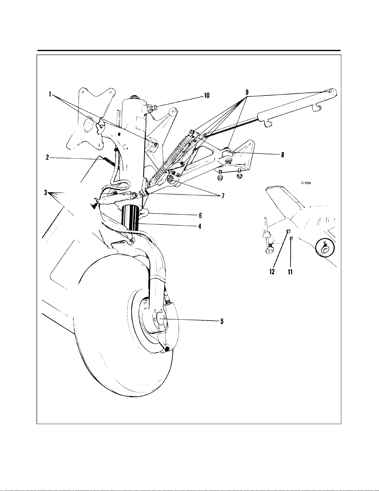
PIPER AIRCRAFT
PA-28RT-201 / 201T
*MAINTENANCE MANUAL
Figure 12-4. Lubrication Chart (Landing Gear, Main) (cont)
1E1
12-20-32
Page 12-18
December 1, 1978
Page 98
PIPER AIRCRAFT
PA-28RT-201 / 201T
*MAINTENANCE MANUAL
COMPONENT LUBRICANT FREQUENCY
1. NOSE GEAR STRUT HOUSING GREASE FITTING MIL-G-23827 100 HRS
2. NOSE GEAR PIVOT POINT AND HYDRAULIC
CYLINDER ROD END MIL-L-7870 100 HRS
3. NOSE GEAR DOOR RETRACTION MECHANISM MIL-L-7870 100 HRS
4. NOSE GEAR DOOR HINGES MIL-L-7870 100 HRS
5. EXPOSED OLEO STRUT MIL-L-60326 100 HRS
6. NOSE WHEEL BEARINGS TEXACO MARFAX ALL
7. NOSE GEAR DRAG LINK ASSEMBLIES MIL-G-23827 100 HRS
8. NOSE GEAR TORQUE LINK ASSEMBLY AND
STRUT HOUSING MIL-G-23827 100 HRS
9. DOWNLOCK, ROLLER TENSION SPRING, SHIMMY
DAMPENER AND ALIGNING ROLLER PIVOT POINTS MIL-L-7870 100 HRS
10. STEERING BELLCRANK PIVOT POINTS AND
ROD ENDS MIL-G-7711 100 HRS
11. NOSE GEAR OLEO STRUT FILLER POINT MIL-H-5606 AS REQUIRED
12. BUNGEE SPRING MIL-G-7711 100 HRS
13. FIREWALL BUNGEE SEAL AERO LUBRIPLATE. MAG-1
PURPOSE GREASE OR
MOBIL GREASE 77 (OR
MOBIL EP2 GREASE) 100 HRS
OR AERO SHELL #7 100 HRS
SPECIAL INSTRUCTIONS
1. Nose Wheel Bearings - Disassemble and clean with a dry type solvent. Ascertain that grease is packed between
the roller and cone. Do not pack grease in wheel housing. Wheel bearings require cleaning and repacking after
exposure to an abnormal quantity of water.
2. Oleo Struts - Fill per instructions on unit or refer to Maintenance Manual
THIS SPACE INTENTIONALLY LEFT BLANK
Figure 12-5. Lubrication Chart (Landing Gear, Nose)
1E2
12-20-32
Page 12-19
Revised: July 24, 1981
Page 99
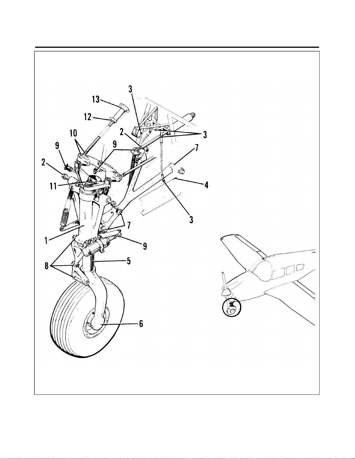
PIPER AIRCRAFT
PA-28RT-201 / 201T
*MAINTENANCE MANUAL
Figure 12-5. Lubrication Chart (Landing Gear, Nose) (cont)
1E3
12-20-32
Page 12-20
December 1, 1978
Page 100
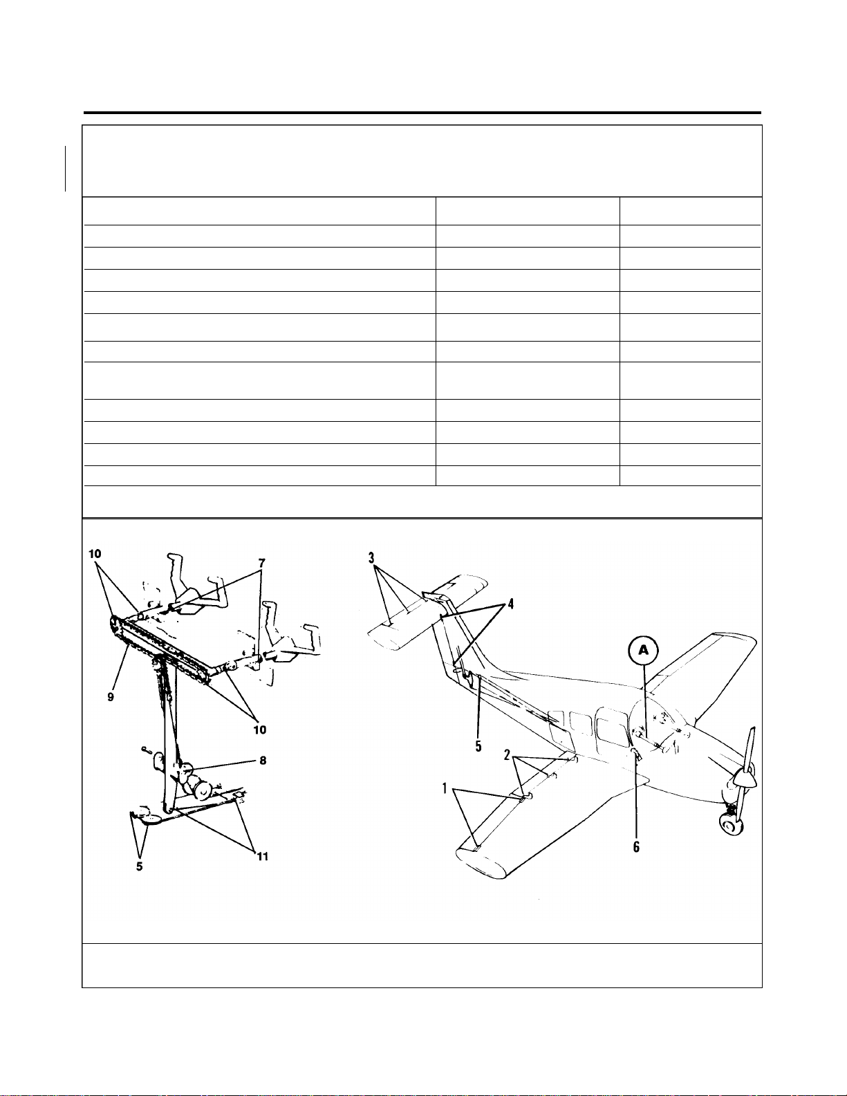
PIPER AIRCRAFT
PA-28RT-201 / 201T
*MAINTENANCE MANUAL
—CAUTION—
Do not lubricate control wheel shaft or bushing. Clean only
using alcohol or other suitable solvent.
COMPONENT LUBRICANT FREQUENCY
1. AILERON HINGE PINS MIL-L-7870 100 HRS
2. FLAP HINGE BEARINGS MIL-L-7870 100 HRS
3. STABILATOR HINGE PINS MIL-L-7870 100 HRS
4. RUDDER HINGE BEARINGS MIL-L-7870 100 HRS
5. CONTROL CABLE PULLEYS MIL-L-7870 100 HRS
6. TRIM CONTROL WHEEL MIL-L-7870 100 HRS
7. O-RING, CONTROL SHAFT BUSHING PARKER O-RING*
LUBRICANT AS REQUIRED
8. TEE BAR PIVOT POINT MIL-L-7870 100 HRS
9. CONTROL COLUMN CHAIN MIL-L-7870 500 HRS
10. CONTROL COLUMN FLEX. JOINTS AND SPROCKET MIL-L-7870 100 HRS
11. STABILATOR CONTROL MIL-L-7870 100 HRS
Disassemble O-ring retainer plates from instrument panel; lubricate O-ring and reassemble.
*SPECIAL INSTRUCTIONS
Figure 12-6. Lubrication Chart (Control System)
1E4
Interim Revision: July 30, 1986
12-20-32
Page 12-21
 Loading...