

DISPLAY
P.BASS SKIP ON A.TRACK D.VOL A.VOL DIG ANA [ 32 44 48 ]RDM ALL RPT-1SFC
CD 2 CD 3 CDR
1st TRACK
CD CD
REC
DIGITAL OUT
RECORDING
CDR
SPC
(DEMO)
CD—RW
REC
FINALIZE
–TUNING+
1
¡
FM/AM TAPE
6
7
P.BASS
P
U
ERASE
N
U
O
EACH
D
0
TRACK NO.
WRITE(MANUAL) AUTO/MANUAL
CD1
CD2
CD3
STEREO MONO TUNED
PGM
12
PHONO
E
T
N
E
J
D
A
K
C
O
L
C
/
R
E
M
I
T
PHONES
STEREO CD/CD-R RECEIVER XR-MR7
LINE
CD 1
3COMPACT DISC MULTI CHANGER
S
4
.
T
.
–
DIRECT REC SELECT
FINALIZE
S
R
.
M
T
E
.
N
+
U
¢
/
M
ALL 1 TRACK
O
CD1
CDR CDR CDR
ANALOG DIGITAL
-–
+-–+
¶ 6 7
REC LEVEL REC LEVEL
COMPACT DISC DIGITAL RECORDER
LINE2 IN LINE2 OUTOPTICAL
CD
1
0
2
0
3
0
MULTI JOG VOLUME
STANDBY/ON
STEREO CD / CD-R RECEIVER
XR-MR7
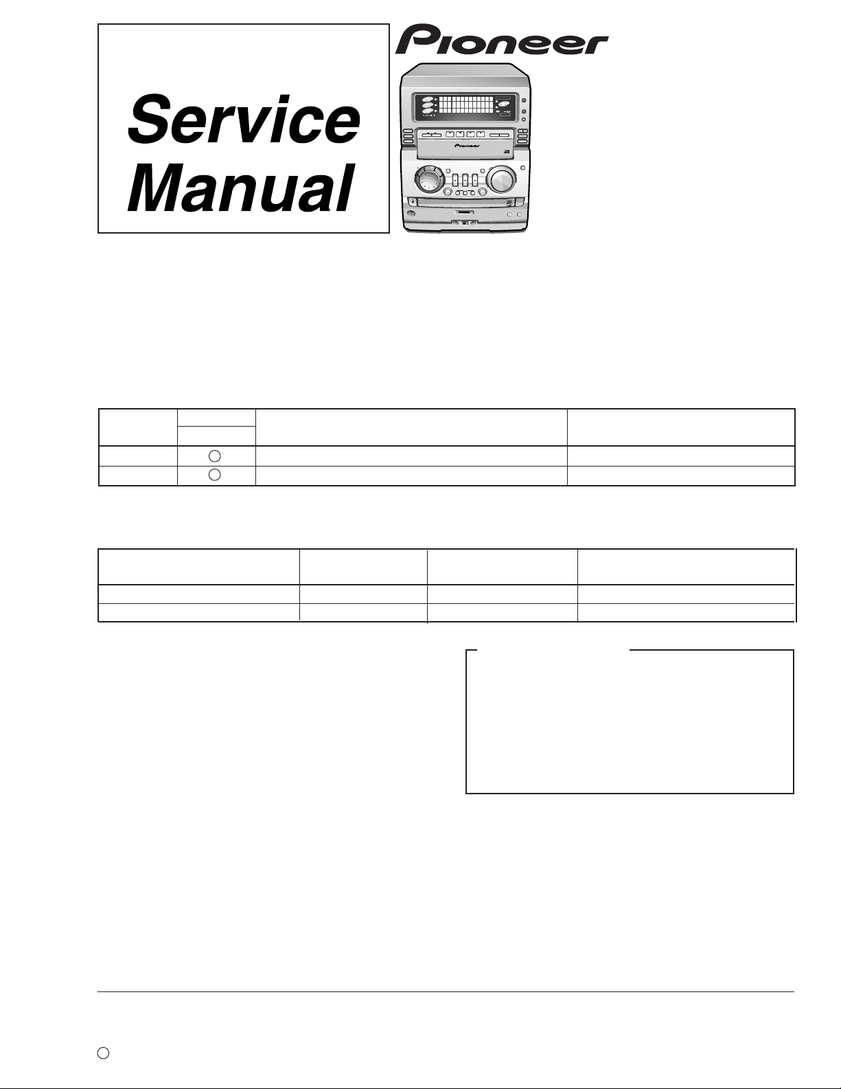
THIS MANUAL IS APPLICABLE TO THE FOLLOWING MODEL(S) AND TYPE(S).
Type
KU/CA AC120V
MY AC220-230V
Model
XR-MR7
Power Requirement Remarks
ORDER NO.
RRV2250
¶ This product is a system(s) component.
Be sure to connect it to the prescribed system component(s), otherwise damage may result.
Component Model Service manual Remarks
STEREO CD/CD-R RECEIVER XR-MR7 RRV2250 This manual.
SPEAKER SYSTEM S-MR7 RRV2248
FOR U.S. MODELS
NECESSARY INFORMATION FOR DHHS
RULES MARKED ON THE REAR BASE AND ON
THE TOP OF CD MECHANISM AS BELOW.
DANGER – LASER RADIA TION WHEN OPEN.
AVOID DIRECT EXPOSURE TO BEAM.
CONTENTS
1. SAFETY INFORMATION
2. EXPLODED VIEWS AND PARTS LIST
.......................................
.................
3. BLOCK DIAGRAM AND SCHEMATIC DIAGRAM..14
4. PCB CONNECTION DIAGRAM
5. PCB PARTS LIST
6. ADJUSTMENT
................................................
.....................................................
...........................
50
71
81
2
4
7. GENERAL INFORMATION
7.1 DIAGNOSIS
...................................................
7.1.1 DISASSEMBLY
7.1.2 SEQUNCE AFTER THE POWER ON
7.2 PARTS
7.2.1 IC
7.2.2 DISPLAY
.........................................................
...........................................................
................................................
8. PANEL FACILITIES AND SPECIFICATIONS
..................................
........................................
......
.....
91
91
91
96
100
100
103
104
PIONEER CORPORATION 4-1, Meguro 1-chome, Meguro-ku, Tokyo 153-8654, Japan
PIONEER ELECTRONICS SERVICE, INC. P.O. Box 1760, Long Beach, CA 90801-1760, U.S.A.
PIONEER ELECTRONIC (EUROPE) N.V. Haven 1087, Keetberglaan 1, 9120 Melsele, Belgium
PIONEER ELECTRONICS ASIACENTRE PTE. LTD. 253 Alexandra Road, #04-01, Singapore 159936
c
PIONEER CORPORATION 1999
T – ZZR DEC. 1999 Printed in Japan
XR-MR7
1. SAFETY INFORMATION
This service manual is intended for qualified service technicians ; it is not meant for the casual do-ityourselfer. Qualified technicians have the necessary test equipment and tools, and have been trained
to properly and safely repair complex products such as those covered by this manual.
Improperly performed repairs can adversely affect the safety and reliability of the product and may
void the warranty. If you are not qualified to perform the repair of this product properly and safely, you
should not risk trying to do so and refer the repair to a qualified service technician.
WARNING
This product contains lead in solder and certain electrical parts contain chemicals which are known to the state of California to cause
cancer, birth defects or other reproductive harm.
Health & Safety Code Section 25249.6 – Proposition 65
NOTICE
(FOR CANADIAN MODEL ONLY)
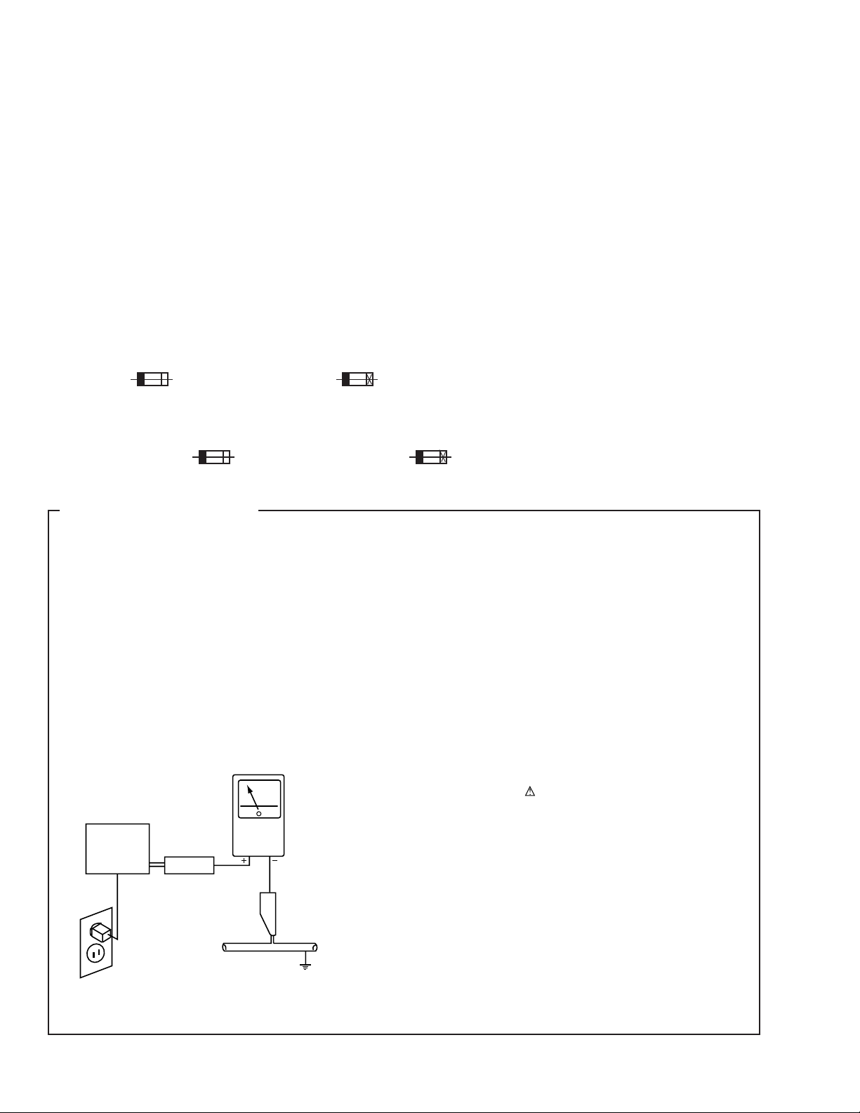
Fuse symbols (fast operating fuse) and/or (slow operating fuse) on PCB indicate that replacement parts must
be of identical designation.
REMARQUE
(POUR MODÈLE CANADIEN SEULEMENT)
Les symboles de fusible (fusible de type rapide) et/ou (fusible de type lent) sur CCI indiquent que les pièces
de remplacement doivent avoir la même désignation.
(FOR USA MODEL ONLY)
1. SAFETY PRECAUTIONS
The following check should be performed for the
continued protection of the customer and service
technician.
LEAKAGE CURRENT CHECK
Measure leakage current to a known earth ground (water
pipe, conduit, etc.) by connecting a leakage current tester
such as Simpson Model 229-2 or equivalent between the
earth ground and all exposed metal parts of the appliance
(input/output terminals, screwheads, metal overlays, control
shaft, etc.). Plug the AC line cord of the appliance directly
into a 120V AC 60Hz outlet and turn the AC power switch
on. Any current measured must not exceed 0.5mA.
Reading should
not be above
0.5mA
Earth
ground
Device
under
test
Also test with
plug reversed
(Using AC adapter
plug as required)
Leakage
current
tester
Test all
exposed metal
surfaces
ANY MEASUREMENTS NOT WITHIN THE LIMITS
OUTLINED ABOVE ARE INDICATIVE OF A POTENTIAL
SHOCK HAZARD AND MUST BE CORRECTED BEFORE
RETURNING THE APPLIANCE TO THE CUSTOMER.
2. PRODUCT SAFETY NOTICE
Many electrical and mechanical parts in the appliance
have special safety related characteristics. These are
often not evident from visual inspection nor the protection
afforded by them necessarily can be obtained by using
replacement components rated for voltage, wattage, etc.
Replacement parts which have these special safety
characteristics are identified in this Service Manual.
Electrical components having such features are identified
by marking with a
in this Service Manual.
The use of a substitute replacement component which does
not have the same safety characteristics as the PIONEER
recommended replacement one, shown in the parts list in
this Service Manual, may create shock, fire, or other hazards.
Product Safety is continuously under review and new
instructions are issued from time to time. For the latest
information, always consult the current PIONEER Service
Manual. A subscription to, or additional copies of, PIONEER
Service Manual may be obtained at a nominal charge from
PIONEER.
on the schematics and on the parts list
AC Leakage Test
2
XR-MR7
THIS PIONEER APPARATUS CONTAINS
LASER OF CLASS ΙΙΙ b.
SERVICING OPERATION OF THE APPARATUS
SHOULD BE DONE BY A SPECIALLY
INSTRUTED PERSON.
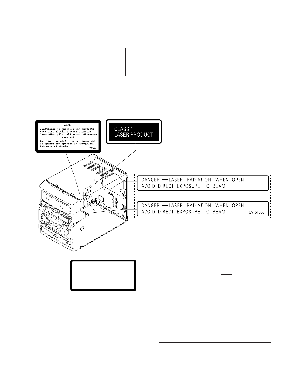
LABEL CHECK
MY Type
IMPORTANT
LASER DIODE CHARACTERISTICS
MAXIMUM OUTPUT POWER: 23 mW
WAVELENGTH: 778 – 787 nm
MY Type
VRW-328
KU/CA Type
Printed on Rear Panel
USYNLIG LASERSTRÅLING VED ÅBNING NÅR SIKKERHED SAFBRYDERE ER UDE AF FUNKTION.
UNDGÅ UDSÆTTELSE FOR STRÅLING
UNSICHTBARE LASER-STRAHLUNG TRITT AUS, WENN DECKEL
(ODER KLAPPE) GEÖFFNET IST! NICHT DEM STRAHL AUSSETZEN!
ADVARSEL
VORSICHT!
VRW1094
MY Type
Additional Laser Caution
1. Laser Interlock Mechanism
The position of the switch (S601) on the SERVO
MECHANISM Assy for detecting loading state is detected
by the system microprocessor, and the design prevents
laser diode oscillation when the switch (S601) is not on
CLMP terminal side (CLMP signal is OFF or high level.).
Thus, the interlock will no longer function if the switch
(S601) is deliberately set to CLMP terminal side (low
level).
The interlock also does not function in the test mode ∗.
Laser diode oscillation will continue, if pin 1 of M51593FP
(IC101) on the PRE-AMP BOARD ASSY mounted on the
CD-R PICKUP is connected to GND, or pin 19 is
connected to low level (ON), or else the terminals of Q101
are shorted to each other (fault condition).
2. When the cover is opened with the servo mechanism
block removed and turned over, close viewing of the
objective lens with the naked eye will cause exposure to a
Class 1 laser beam.
∗ Refer to page 84.
3
XR-MR7
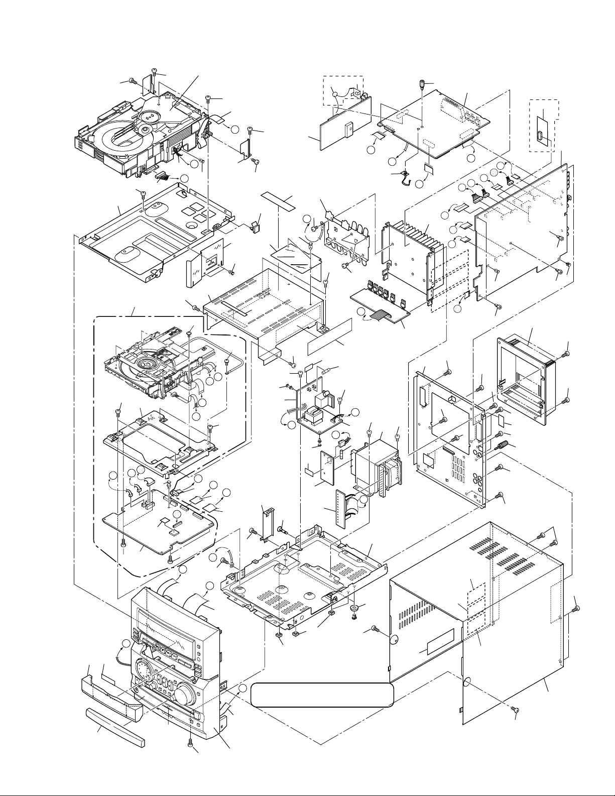
2. EXPLODED VIEWS AND PARTS LIST
NOTES:• Parts marked by "NSP" are generally unavailable because they are not in our Master Spare Parts List.
The mark found on some component parts indicates the importance of the safety factor of the part.
•
Therefore, when replacing, be sure to use parts of identical designation.
Screws adjacent to mark on the product are used for disassembly.
•
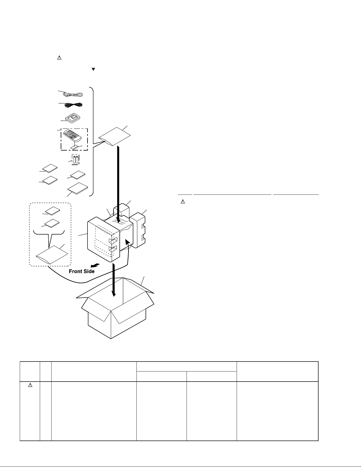
2.1 PACKING
1
2
14
15
MY:Only
16
17
3
V
K
O
A
L
R
A
O
K
E
4
S
DISC DISC DISC
F
S
C
L
E
E
P
P
.B
POWER
C
A
L
S
E
S
A
R
D
IS
P
P
L
A
G
Y
M
A
U
X
R
E
P
E
A
T
R
A
N
D
O
M
S
T
A
T
REMOTE CONTROL UNIT CU-XR025
IO
N
M
O
N
O
B
A
N
D
12
5
6
13
(1) PACKING PARTS LIST
Mark No. Description Part No.
11
7
8
12
9 (1/2)
9(2/2)
10
1 Power Cord See Contrast table (2)
2 FM Antenna See Contrast table (2)
3 AM Loop Antenna ATB7009
4 Remote Control Unit AXD7241
(CU-XR059)
5 Battery Cover AZA7378
NSP 6 Dry Cell Battery (R6P, AA) VEM-013
7 Packing Sheet AHG7003
8 Front Pad AHA7281
9 Rear Pad LR AHA7282
10 Packing Case See Contrast table (2)
NSP 11 Warranty Card See Contrast table (2)
12 Polyethylene Bag Z21-038
(0.03 x 230 x 340)
13 Operating Instructions See Contrast table (2)
(English)
14 Operating Instructions See Contrast table (2)
(English/French)
15 Operating Instructions See Contrast table (2)
(German/Italian)
16 Operating Instructions See Contrast table (2)
(Dutch/Swedish)
17 Operating Instructions See Contrast table (2)
(2) CONTRAST TABLE
(Portuguese/Spanish)
XR-MR7/MY and /KU/CA are constructed the same except for the following:
Mark
No.
Symbol and Description
MY type KU/CA type
1 Power Cord ADG1127 ADG7021
2 FM Antenna ADH7005 ADH7004
10 Packing Case AHD7849 AHD7848
NSP 11 Warranty Card ARY7022 ARY7033
13 Operating Instructions (E) Not used ARB7213
14 Operating Instructions (E/F) ARE7238 Not used
15 Operating Instructions (G/I) ARE7239 Not used
16 Operating Instructions (D/S) ARC7290 Not used
17 Operating Instructions (P/Sp) ARC7291 Not used
4
Part No.
Remarks
A
D
D
B
C
A
R
R
M
K
I
S
G
H
G
F
E
O
P
Q
E
H
F
J
K
L
M
N
N
B
Q
P
O
S
L
I
C
J
74
71
MY Type
Only
MY Type
Only
44
3
4
61
1
41
42
29
39
37
20
52
52
52
52
52
52
52
53
53
53
51
51
51
51
51
29
51
51
67
76
43
45
48
45
45
25
26
47
5
9
38
38
10
6
7
49
66
65
70
69
77
8
63
64
31
27
28
37
60
60
15
50
73
51
19
52
52
53
75
55
53
52
2
30
13
13
13
13
36
33
21
35
12
17
21
18
34
14
16
52
51
22
29
23
24
32
51
40
51
58
59
57
65
58
59
56
62
Refer to "2.6 3CD MICROCHANGER MECHA "
Refer to "2.3 FRONT PANEL SECTION"
Refer to "2.4 CD-R CORE ASSY (1/2)
2.5 CD-R CORE ASSY (2/2) "
11
2.2 EXTERIOR SECTION
XR-MR7
5

XR-MR7
(1) EXTERIOR SECTION PARTS LIST
Mark No. Description Part No. Mark No. Description Part No.
NSP 2 CD-R CORE ASSY PXA1625
1 FM/AM TUNER Module See Contrast table (2)
3 AF ASSY See Contrast table (2)
4 AMP ASSY See Contrast table (2)
5 REG ASSY AWU7468
6 SECONDARY ASSY AWU7451
7 PRIMARY ASSY See Contrast table (2)
8 SUBTRANS ASSY See Contrast table (2)
9 AC IN/OUT ASSY See Contrast table (2)
10 Power Transformer See Contrast table (2)
11 Fuse (FU 2 : ) See Contrast table (2)
12 6P Connector Assy ADE7055
13 Screw BBZ30P080FCC
NSP 14 3CD MICROCHANGER MECH AXA7077
15 27P FFC/30V ADD7203
(DIS CN5601 ↔ AF CN5501)
16 16P FFC/60V ADD7178
(AF CN1101 ↔ 3CD MECHA)
17 21P FFC/60V ADD7200
(AF CN7701 ↔ CDR CN501)
18 15P FFC/60V ADD7201
(AF CN7702 ↔ CDR CN301)
19 9P FFC/60V ADD7205
(AF CN3201 ↔ FRO. CN5403)
20 Fuse (FU 1 : ) See Contrast table (2)
21 Screw BBT30P080FCC
22 2mm Connector ASSY 6P ADE7051
(AF CN1301 ↔ 3CD CN8002)
23 Connector ASSY 11P PG11KK-G20
(AF CN1302 ↔ 3CD CN8003)
NSP 24 Mini Clamper VEC1597
NSP 25 Heat Sink ANH7115
26 Heat Plate ANG7266
NSP 27 Chassis ANA7101
28 Leg Assy AEC7248
29 Pla Rivet DEC1704
30 Tray Panel (CD-R) AAK7712
NSP 31 PCB Holder PNW2029
32 Flexible Holder AEC7252
33 CD-R CORE ASSY PYY1273
34 Radiator Sheet PEB1305
NSP 35 PCB Spacer AEC1371
NSP 36 Mecha Base PNB1613
37 PCB Spacer (3x12) AEC1372
38 Screw IBZ40P060FCC
39 Shield Case ANG7272
40 Side Stay ANG7261
41 CD Stay ANG7259
42 CD Sheet AEC7253
43 Rivet (PLASTIC: 3x4.5) RBM–003
44 Tapping Card Spacer AEC7098
45 Card Spacer AEC7214
NSP 46 PCB Spacer AEC7254
47 Rear Panel R See Contrast table (2)
48 Rear Cover AMR7310
49 Bonnet Case R AZN7824
50 Tray Panel (CD) See Contrast table (2)
51 Screw BBZ30P060FCC
52 Screw BBZ30P080FNI
53 Screw BBZ30P080FZK
54 Screw BPZ30P060FMC
55 Terminal Screw AKE- 031
56 Supporter Plate L ANG7290
57 Supporter Plate R ANG7291
58 Screw IPZ30P060FMC
59 Screw PBZ30P120FMC
60 Spacer R AEB7189
61 Tapping Card Spacer AEC7262
62 Harness Lifter DEC1262
63 Fuse Label See Contrast table (2)
64 Fuse Label See Contrast table (2)
65 65 Label See Contrast table (2)
66 Fuse Caution Label See Contrast table (2)
NSP 67 Laser Caution Label See Contrast table (2)
68 Disc Caution Label See Contrast table (2)
69 Caution Label HE See Contrast table (2)
70 Caution Label See Contrast table (2)
71 Ceramic Capacitor See Contrast table (2)
72 Cord Clamper RNH-184
NSP 73 Getter See Contrast table (2)
74 Earth Plate See Contrast table (2)
75 Speaker Caution Label ARW7080
76 LEGATO ASSY See Contrast table (2)
77 Caution Label (F) See Contrast table (2)
6
(2) CONTRAST TABLE
XR-MR7/MY and /KU/CA are constructed the same except for the following:
Mark
No.
1 FM/AM TUNER Module AXQ7068 AXQ7065
3 AF ASSY AWU7460 AWU7448
4 AMP ASSY AWU7464 AWU7555
7 PRIMARY ASSY AWU7469 AWU7457
8 SUBTRANS ASSY AWU7471 AWU7459
9 AC IN/OUT ASSY AWU7470 AWU7458
10 Power Transformer ATS7271 ATS7272
11 Fuse (FU 2 : 4A/125V) Not used REK1082
11 Fuse (FU 2 : T2AL250V) AEK1057 Not used
20 Fuse (FU 1 : 5A/125V) Not used REK1083
20 Fuse (FU 1 : T2.5AL250V) AEK1058 Not used
47 Rear Panel R ANC7880 ANC7879
50 Tray Panel (CD) AAK7746 AAK7715
NSP 63 Fuse Label AAX1581 AAX1419
NSP 64 Fuse Label AAX1580 AAX1194
Symbol and Description
MY type KU/CA type
Part No.
XR-MR7
Remarks
65 65 Label Not used ARW7050
NSP 67 Laser Caution Label Not used PRW1516
66 Fuse Caution Label Not used ARW7081
68 Disc Caution Label Not used PRW1532
69 Caution Label HE PRW1233 Not used
70 Caution Label VRW1094 Not used
71 Ceramic Capacitor CKPUYB102K50 Not used
73 Getter ARW7086 ARW7077
74 Earth Plate XNG3015 Not used
76 LEGATO ASSY AWU7525 Not used
77 Caution Label (F) VRW–328 Not used
7
XR-MR7
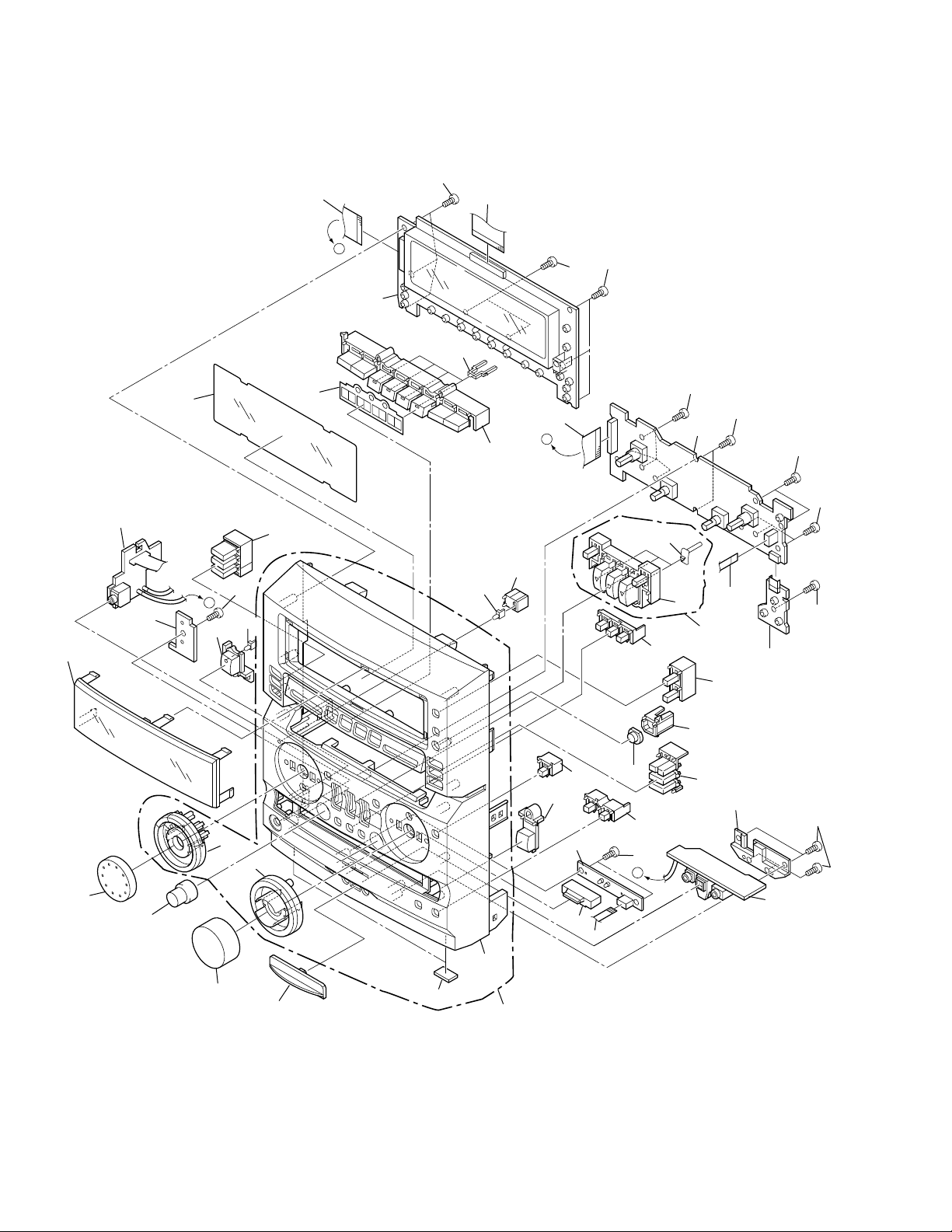
2.3 FRONT PANEL SECTION
5
27
6
23
1
PCB Cutting
Parts
21
B
19(4/4)
27
11
16 (1/2)
29
A
2
14
13(1/2)
17
A
12(2/2)
27
27
27
5
35
22
12(1/2)
27
3
27
27
31
27
20
30
15
25
33
24
13(2/2)
36
18
19(1/4)
27
B
16 (2/2)
Front Panel Cutting Parts
27
4
19(3/4)
19(2/4)
9
8
26
34
7
28
32
10
8
(1) FRONT PANEL SECTION PARTS LIST
Mark No. Description Part No.
1 H.P ASSY AWU7453
2 DISPLAY ASSY AWU7461
3 SW JOG ASSY AWU7466
4 FRONT LINE ASSY See Contrast table (2)
5 21P FFC/60V ADD7202
6 27P FFC/60V ADD7203
7 Rubber Sheet AEB1111
8 VOL Ring R AAB7219
9 Button RE AAD7559
10 Function Lens PNW2796
XR-MR7
NSP 11 Indicate Lens AAK7085
NSP 22 Button RF AAD7560
NSP 26 Front Panel RK AMB7690
NSP 35 Button Lens MRF AAK7691
12 Button RD AAD7554
13 Button RB AAD7553
14 Button Lens MRB AAK7690
15 Button RA AAD7557
16 Button RC AAD7558
17 LED Lens PNW2745
18 Receiv Lens AAK7586
19 Button RG ASSY AXG7087
20 Button RF ASSY AXG7086
21 FL Plate AAK7718
23 Display Window R AAK7710
24 VOL Knob R AAB7218
25 Jog Knob R AAB7217
27 Screw BPZ30P080FZK
28 Front Panel RK ASSY AXG7091
29 Shield Sheet R AED7041
30 CDR SW ASSY AWU7517
31 5P FFC/60V ADD7204
32 CDR LED ASSY AWU7467
33 Knob R AAB7216
34 Cap AAK7713
(2) CONTRAST TABLE
XR-MR7/MY and /KU/CA are constructed the same except for the following:
Mark
No.
Symbol and Description
MY type KU/CA type
4 FRONT LINE ASSY AWU7450 AWU7438
Part No.
Remarks
9
XR-MR7
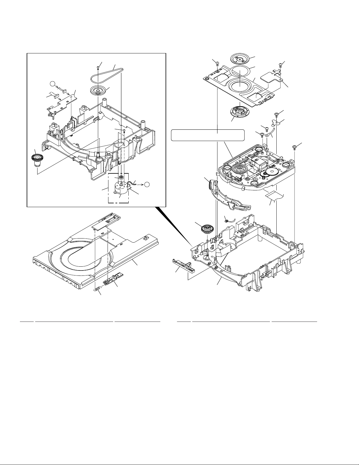
2.4 CD-R CORE ASSY (1/2)
• Bottom View
A
18
13
1
20
9
12
7
26
25
Refer to
"2.5 CD-R CORE ASSY (2/2)"
23
31
24
19
5
28
26
29
5
30
5
6
21
4
17
8
CD-R CORE ASSY(1/2) PARTS LIST
•
3
A
2
11
16
15
27
22
14
10
Mark No. Description Part No. Mark No. Description Part No.
NSP 1 LOADING A Assy PWZ3760
NSP 2 LOADING B Assy PWZ3761
3 Connector Assy PG02KK-E15
(LOADING B CN551 ↔ LOADING A CN502)
4 DC Motor (LOADING) PXM1027
5 Screw DBA1006
6 Motor Pulley PNW1634
7 Screw VBA1055
8 Tray Stopper Spring VBH1277
9 Rubber Belt VEB1260
10 Loading Base VNL1844
11 Tray VNL1731
12 Gear Pulley VNL1733
13 Loading Gear VNL1734
14 Drive Gear VNL1735
15 Drive Cam VNL1736
16 Lock Plate VNL1820
NSP 28 Earth Lead Unit PDF1200
17 Tray Stopper VNL1739
18 Connector Assy PF03KK-E37
(LOADING A CN501 ↔ CD-R CORE CN451)
19 Screw BBZ26P040FMC
20 Screw Z39-019
21 Loading Motor Assy VXX2505
22 Binder PEC-107
23 Clamper Plate VNE2068
24 Bridge VNE2069
25 Clamper VNL1738
26 Screw IPZ26P060FMC
27 32P Flexible Cable / 30V PDD1195
(CD-R Pickup ↔ CD-R CORE CN101)
29 Tray Holder PNM1341
30 Stopper DNH2076
31 Spacer PNM1334
10
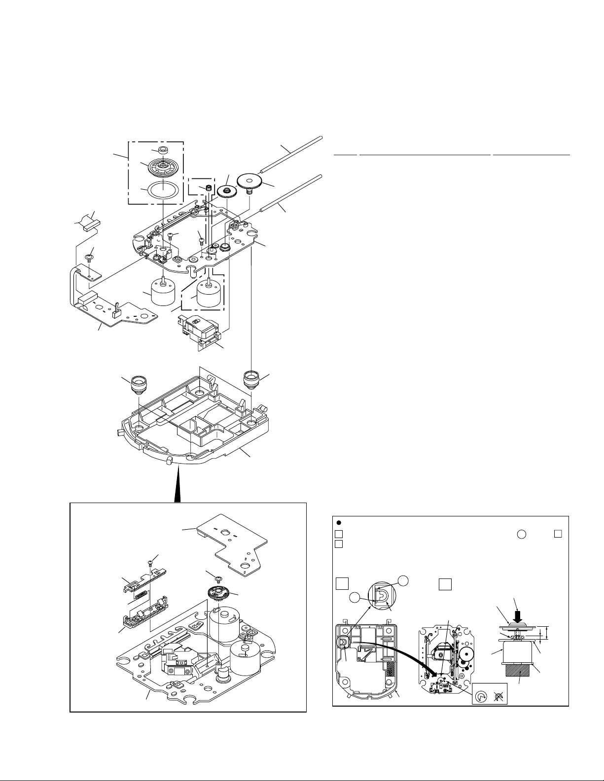
2.5 CD-R CORE ASSY (2/2)
25
17
22
1
20
15
23
9
23
3
7
2
26
4
10
21
16
XR-MR7
CD-R CORE ASSY(2/2) PARTS LIST
•
19
11
18
5
Mark No. Description Part No.
NSP 1 SERVO MECHANISM Assy PWZ3759
2 DC Motor Assy (SPINDLE) PEA1235
NSP 3 DC Motor (CARRIAGE) PXM1042
4 Float Rubber A AEB7063
5 Float Rubber B AEB7066
NSP 6 Rack Spring DBH1285
NSP 7 Reflection Sheet PNM1325
8 Servo Base PNW2853
9 Pinion Gear PNW2854
10 Gear A PNW2855
11 Gear B PNW2856
12 Gear C PNW2857
13 Rack PNW2858
14 Rack Stopper PNW2859
NSP 15 Disc Table PNW2860
16 Carriage Base S PNW2874
17 Connector Assy PG09KK-E17
(SERVO MECHANISM CN601↔CD-R CORE CN452)
18 Guide Bar VLL1488
19 Sub Guide Bar VLL1489
NSP 20 Magnet VYM1024
21 CD-R Pickup PEA1351
22 Screw Z39-018
23 Screw PMZ20P030FMC
24 Screw JGZ17P030FMC
• Bottom View
SERVO MECHANISM
ASSY
14
6
13
Carriage Base S
24
22
12
25 Disc Table Assy PEA1349
26 Carriage Motor Assy PEA1350
8
How to Install the Disc Table
Use nippers or other tool to cut the two sections marked A in figure 1 .
1
While supporting the spindle motor shaft with the stopper, put spacer on
2
top of the carriage base, and stick the disc table on top (takes about 9kg
pressure). Take off the spacer.
1
A
Spacer
A
Spacer
Servo Base
2
Spacer setting
Position
Disc table Assy
(Pressure of about 9kg)
Spacer
Spindle
motor
OK NG
Stopper
11mm
2.8mm
Carriage
Base
PCB
11
XR-MR7
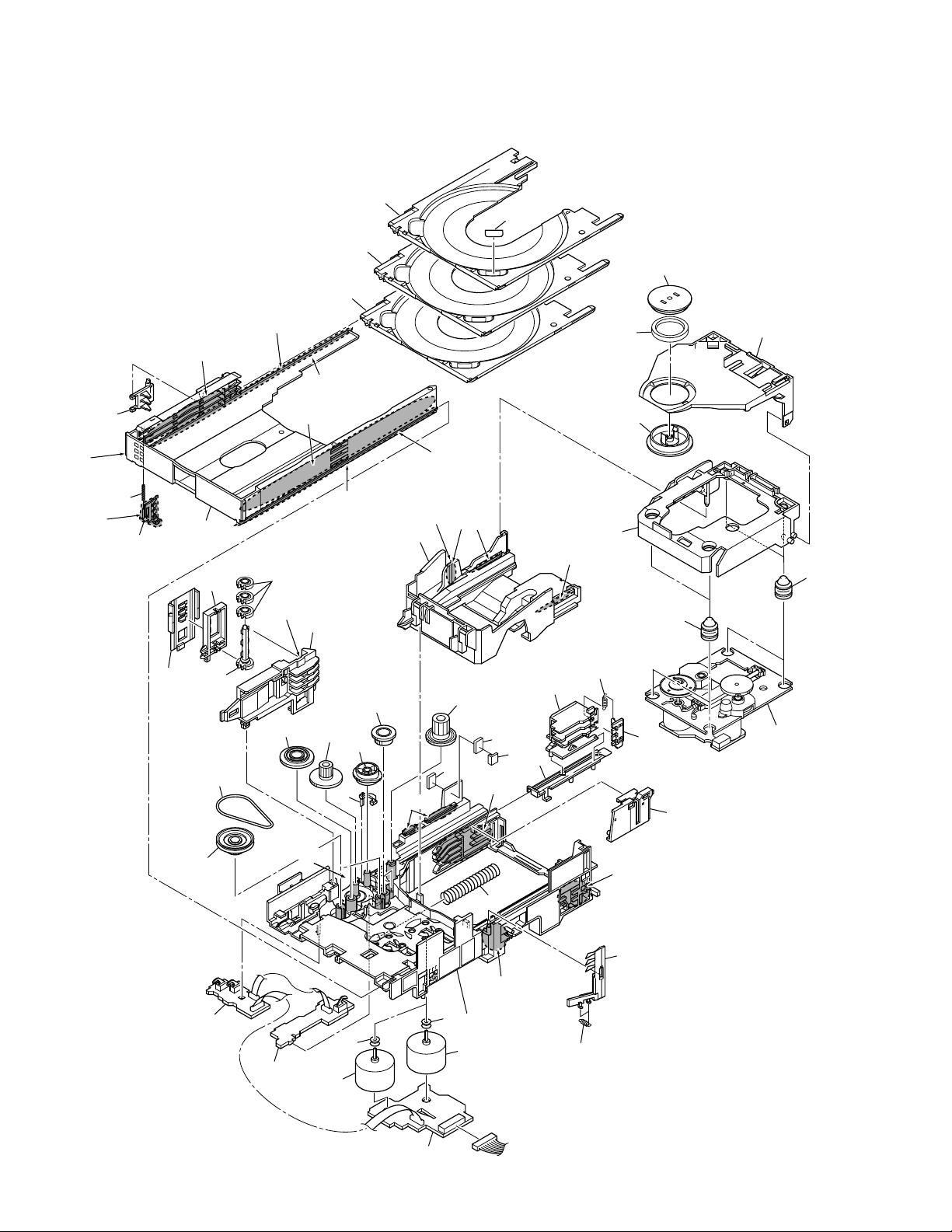
2.6 3CD MICROCHANGER MECHANISM
*1 : Floil (PN-397)
*2 : Dyefree (ME-413A)
*2
(No.36 Sub Tray Part)
38
*2
(Gutter)
*2
(Inside Gutter)
*2
(Bottom Gutter)
36
36
36
37
30
29
28
31
*2
(Left Front
Under Gutter)
35
*2
(Whole)
34
42
15
33
41
18
39
40
*1
(Gutter)
14
*1
(Column)
*2
(Bottom Gutter)
19
12
13
17
16
*1
(Boss)
32
*1
(Gutter)
*2
(Gutter)
*1
(Gutter)
11
43
43
*1
(Rail)
8
44
23
*1
(Gutter)
20
27
22
*1
(Inside Rail)
21
26
(Black)
25
(Blue)
4
24
12
9
*1
(Inside Rail)
2
7
3
5
7
6
5
1
10

3CD MICROCHANGER MECHANISM PARTS LIST
•
Mark No. Description Part No.
1 MOTOR UNIT AWU7431
2 LOADING UNIT AWU7432
3 SELECT UNIT AWU7433
4 PICK–UP UNIT KSM213CCM
5 Slider Motor VXM1033
6 Mecha Base ANW7129
7 Motor Pulley PNW1634
8 Lift Spring ABH7173
9 Home Lever ANW7153
10 HL Spring ABH7182
11 Extended Gear A ANW7138
12 Gear A ANW7136
13 Extended Gear B ANW7139
14 Gear B ANW7137
15 Gear Pully ANW7135
16 Select Lever ANW7143
17 EV Camgear ANW7140
18 Belt AEB7159
19 Elevator Base ANW7132
20 Tray Guide ANW7150
XR-MR7
21 TG Stopper ANW7151
22 TG Spring ABH7175
23 Cam Plate ANW7147
24 Lock Lever ANW7148
25 Float Rubber A (Blue) AEB7063
26 Float Rubber B (Black) AEB7066
27 Float Base ANW7130
28 Clamper Holder ANW7152
29 Yoke ANG7257
30 Clamper Magnet AMF7001
31 Clamper SO XNW3007
32 Swing Base ANW7131
33 Main Tray ANW7133
34 Lock Plate ANW7144
35 Lock Plate Spring ABH7174
36 SUB Tray ANW7134
37 Tray Label ARW7070
38 Stopper Arm ANW7145
39 gear Shaft ANW7142
40 Loading Gear ANW7141
41 Elevator ANW7146
NSP 43 MB Spacer AEC7259
NSP 44 MB3 Spacer AEC7263
42 Elevator Cover ANW7149
13
1
23
XR-MR7
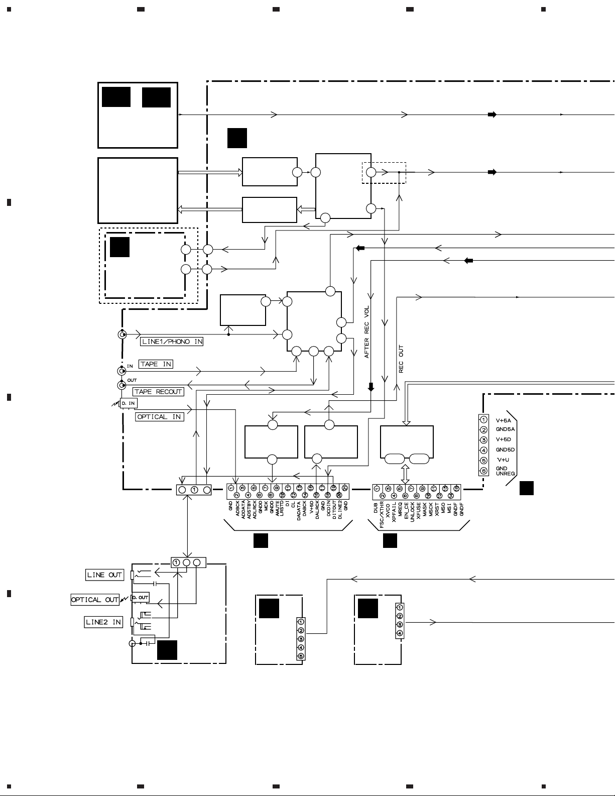
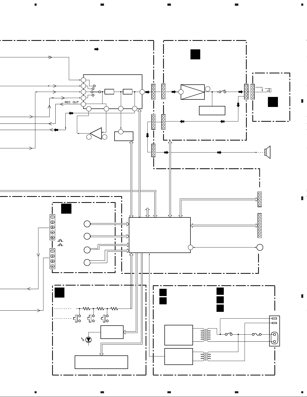
3. BLOCK DIAGRAM AND SCHEMATIC DIAGRAM
3.1 BLOCK DIAGRAM (1/2)
4
A
AA
AB
(TX)
FM/AM TUNER
Module
3CD MICRO
CHANGER
MECHA.
(AXA7077)
LEGATO
V
ASSY
(AWU7525)
MY : Only
B
LINE IN
TAPE PLAY
TAPE REC
IC1901
(PE8001A)
D/A Converter
6 6
11 11
AF ASSY
I
(CXA2570N)
RF Amp.
(M56788FP)
IC3131
(UPC4570G2)
PHONO EQ
IC1101
IC1301
Driver
1
23 72
43
IC1201
(CXD2587Q)
Servo Decoder
62
7
2
IC3101
(TC9164AF)
SIGNAL
SELECTOR
3
4 5
13
11
10
KU/CA:Only
60
(REC)
(REC)
CD ANALOG OUT
CD DIGITAL OUT
(CD)
(REC)
DIGITAL IN
(OPTICAL)
CN3201
C
CN5403
9
5
9
5
FRONT
LINE
ASSY
O
D
1
IC7301
(PMC1800-1)
A / D BLOCK
15
CD-R CORE
B
ASSY : CN501
N
CDR
LED
ASSY
16
IC7401
(PE8001A)
D / A BLOCK
2
CN5962
CN7701
M
CDR
SW
ASSY
IC7501
(PE5113B)
MODE µCOM
11-13 44-46
CD-R CORE
B
ASSY : CN301
CN5954
CN7702
CN7703
CD-R ASSY : CN901
B
14
1234
5
678
XR-MR7
(REC)
CN5952
TX
53
CD
55
CDR
54 31
LINE
51
49
(REC)
L
Rotary
Encoder
Rotary
Encoder
CD-R
30, 50
IC3151
(BA4558F-HT)
BUFFER
1 3
SW JOG ASSY
S5966
JOG
S5965
VOL
S5969
DVOL
S5970
AVOL
: AUDIO SIGNAL ROUTE
IC3031
(LC75396NE)
Input Selector, SFC, E-VR
GEQ
IC3081
(M62457AFP)
Spectram Analyzer IC
E-VR
34
8
AD
28
CN3102
CN521
SPEAKER
TERMINAL
CDR
CD
AMP
IC5501
(PD5545A)
System Control
Microcomputer
MICOM +5V
CN3001
CN3002
AMP
J
IC3301
(STK407-040B)
Power Amp.
14
24
AMP ASSY
RY3601
7
DC DET.
Overload DET.
CN3101
CN3902
Phones
P
J3901
HP ASSY
Speaker
CN2551
System
Connector
(CT-J7)
CN5502
Flash
Microcomputer
ROM
Write
BZ5501
Buzzer
A
B
C
CN5953
K
Key Input
DISPLAY ASSY
(BU2092F)
LED Driver
V5601
(AAV7073)
FL TUBE (included Driver)
5
IC5801
PRIMARY ASSY
REG ASSY
U
SECONDARY ASSY
S
Power Supply
Block
Power
Transformer
T
SUBTRANS ASSY
Q
ACINOUT ASSY
R
RY11
FU1
CN1
AC OUTLET
MY : Only
AC INLET
D
Standby
Power Supply
Block
Standby
Transformer
15
6
7
8
1
23
XR-MR7
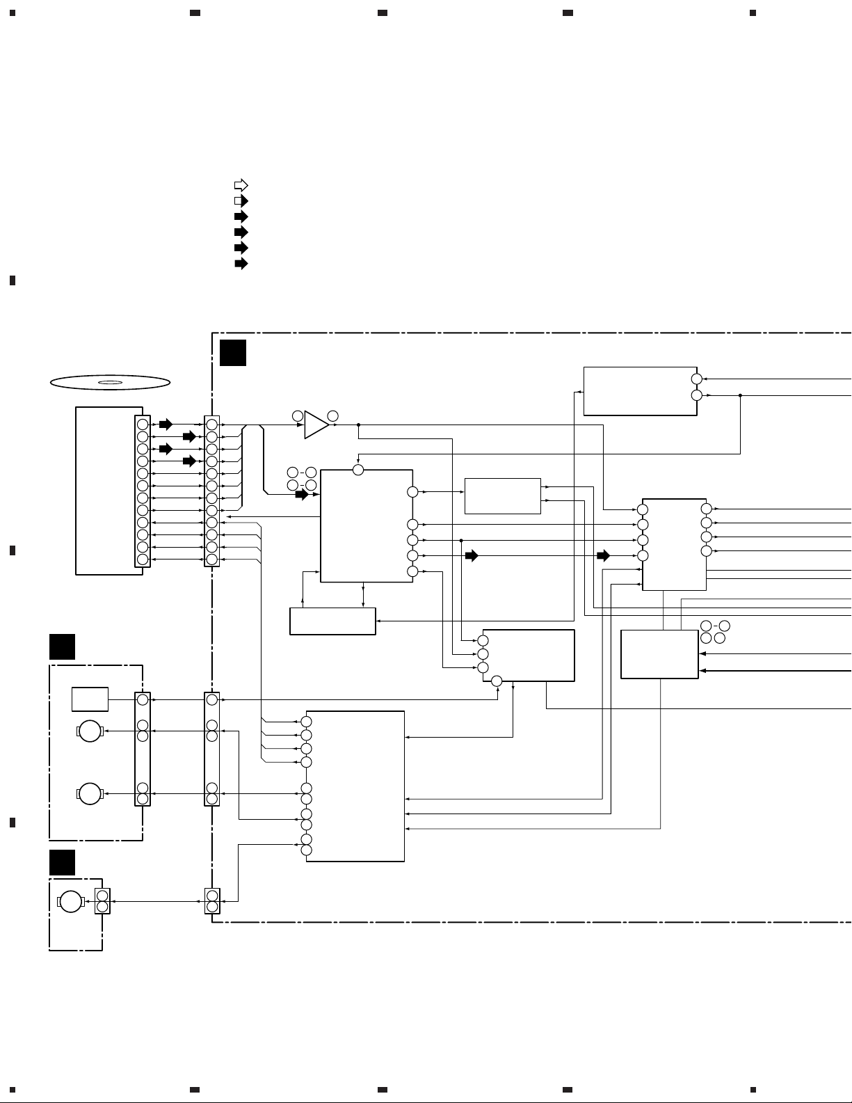
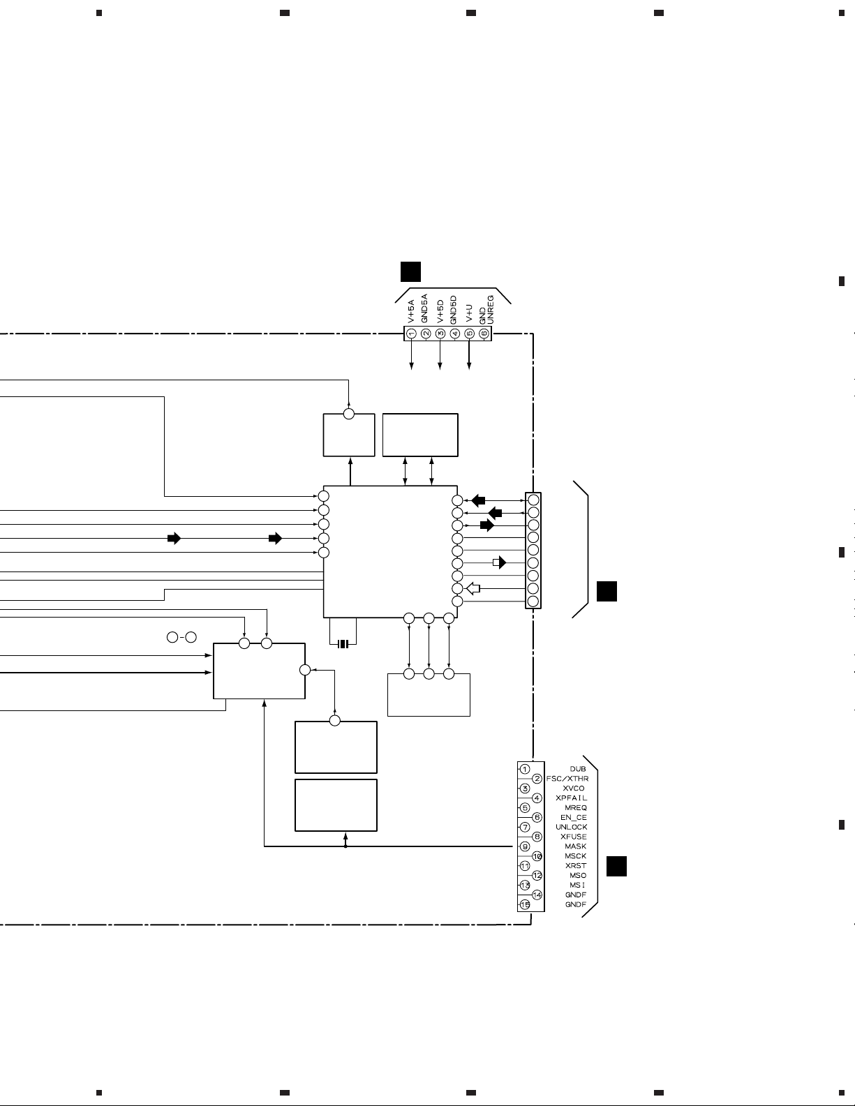
3.2 BLOCK DIAGRAM (2/2 : CD-R)
4
A
Disc (CD, CD-R, CD-RW)
B
PICKUP
PEA1351
CD-R
CN1 CN101
A
10
B
9
C
16
D
15
E
17
F
8
G
14
H
11
FCS+
4
FCS–
1
TRK+
3
TRK–
2
SIGNAL ROUTE
(REC)
: REC SIGNAL (after A/D)
(PB)
(PB)
: PB OUT (before D/A)
(CD)
: DIGITAL CN INPUT
(LI2)
: DIGITAL LINE 2
(DO)
: DIGITAL OUT
: RF SIGNAL ROUTE
CD-R CORE
ASSY
B
RF AMP CIRCUIT
A–D
A
10
B
9
16
15
17
8
14
11
4
1
3
2
A–H
C
D
E
F
G
H
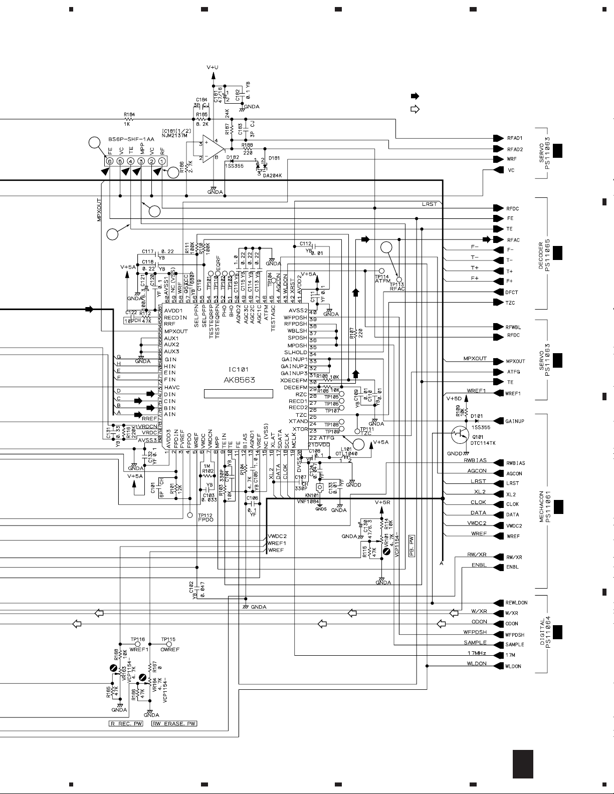
IC181
NJM2137M
6 1
76
73
71 68
RFDC
HF
17.2872MHz
19
IC101
AK8563
RF PROCESSOR
58
11
10
29
46
WRF
FE
TE
RFAC
RFWBL
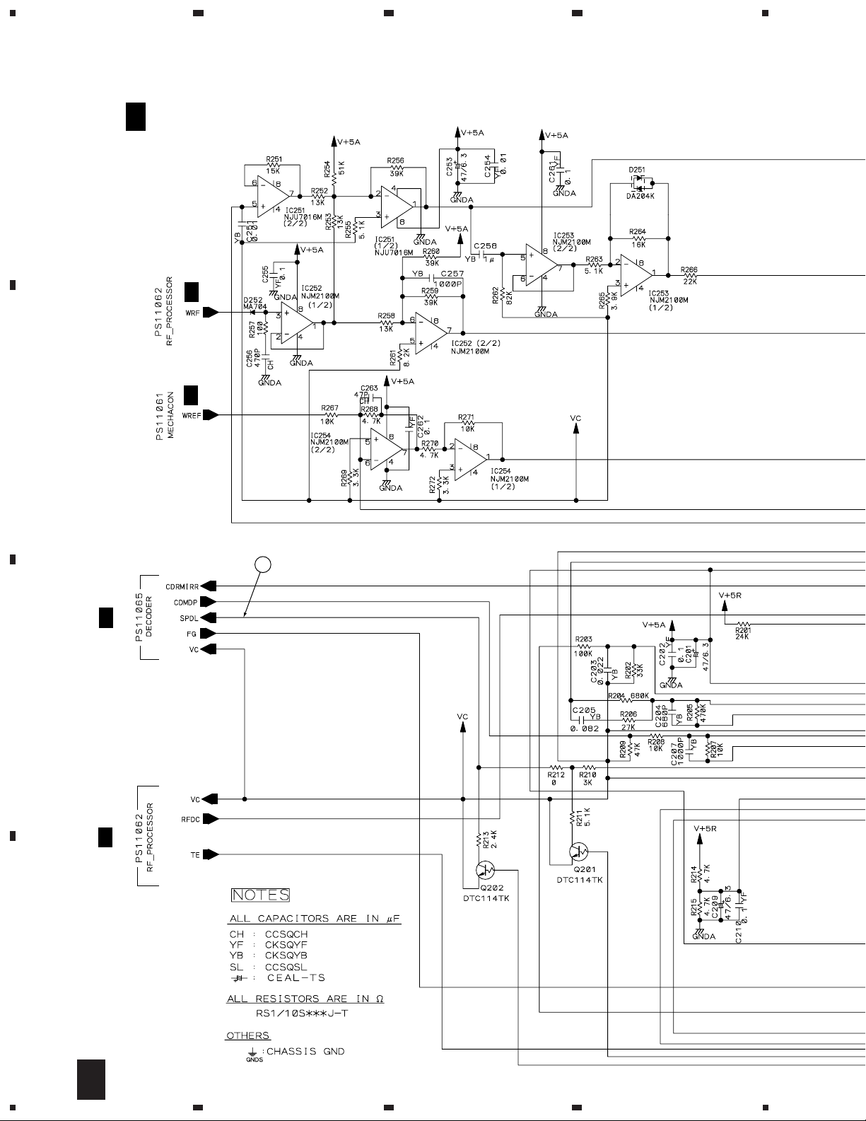
IC251-IC254
RUNNING OPC
CIRCUIT
BLOCK
RFOPC
AOUT
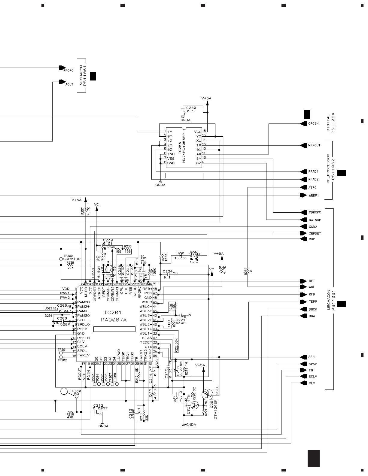
IC431
PDK041A
STRATEGY
CONTROL IC
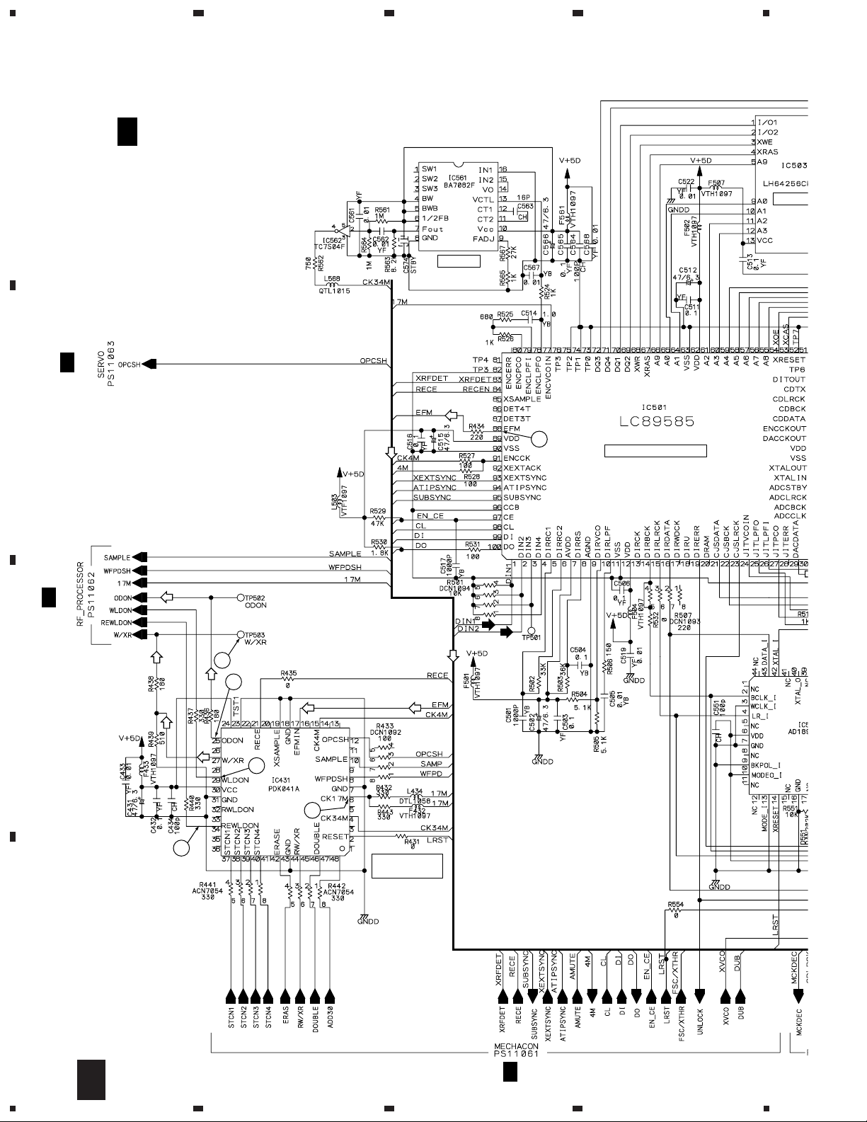
CXD2585Q
CD DECODER
RFDC
43
FE
39
TE
41
RFAC
50
IC401
34.5744MHz
4
17.2872MHz
6
CDLRCK
65
CDBCK
67
CDDATA
66
CDTX
64
LD CONTROL
CIRCUIT
SERVO MECHANISM
C
ASSY
PC651
C
NJL5803K-F1
FG
M
DC MOTOR
ASSY
(SPINDLE)
PEA1235
M
CARRIAGE MOTOR
ASSY (SLIDER)
PEA1350
LOADING B
E
ASSY
CN601
9
3
4
1
2
CN452
FG
SPDL
SL
FG
9
FCS+
3
SPDL
4
2
1
SL
FCS–
TRK+
TRK–
SPDL
L
34
35
IC451
32
M56788FP
31
TRK DRIVER
12
FCS DRIVER
13
SLD DRIVER
SPDL DRIVER
9
10
LOADING DRIVER
14
15
TE
HF
RFWBL
29
IC201
---
PA9007A
SERVO AMP IC
38
19
FG
IC351
PDJ014A
ATIP
DECODER IC
32 37
39 40
AD0-AD7
Address
CN551
M
LOADING
MOTOR
ASSY
VXX2505
1
LLL
2
CN453
4
5
D
16
1234
5
43 36
AD0-AD7
Address
17.2872MHz
CDLRCK
CDBCK
CDDATA
CDTX
AOUT
RFOPC
61 60
IC301
PE5109A
MECHANISM
CONTROL µCOM.
34.5744MHz
7
IC561
BA7082F
VCO IC
76
46
45
44
EFM ENCODER IC
47
X501
16.9344MHz
59
3
IC302
TK11041M-1
TEMPERATURE
SENSOR IC
678
XR-MR7
A
AF ASSY : CN7703
I
CN901
V+ 5D
2
1
48
1
48
30
36
33
35
DIRDATA
V+ U
(DO)
(LI2)
(PB)
(REC)
(CD)
CN301
20
18
19
16
14
13
5
3
2
CN501
DLINE2
DCDIN
DITOUT
DALRCK
DABCK
DADATA
ADLRCK
ADDATA
ADBCK
B
AF ASSY : CN7701
I
C
V+ 5A
IC503
LH64256CK-70
D-RAM
Address Data
IC501
LC89585
15 16 17
DIRBCK
DIRLRCK
2 4 43
IC502
AD1893JST
Fs CONVERTER
IC303
PYY1196
(BR93LC46AF)
EEPROM
AF ASSY : CN7702
I
D
17
5
6
7
8
1
XR-MR7
23
4
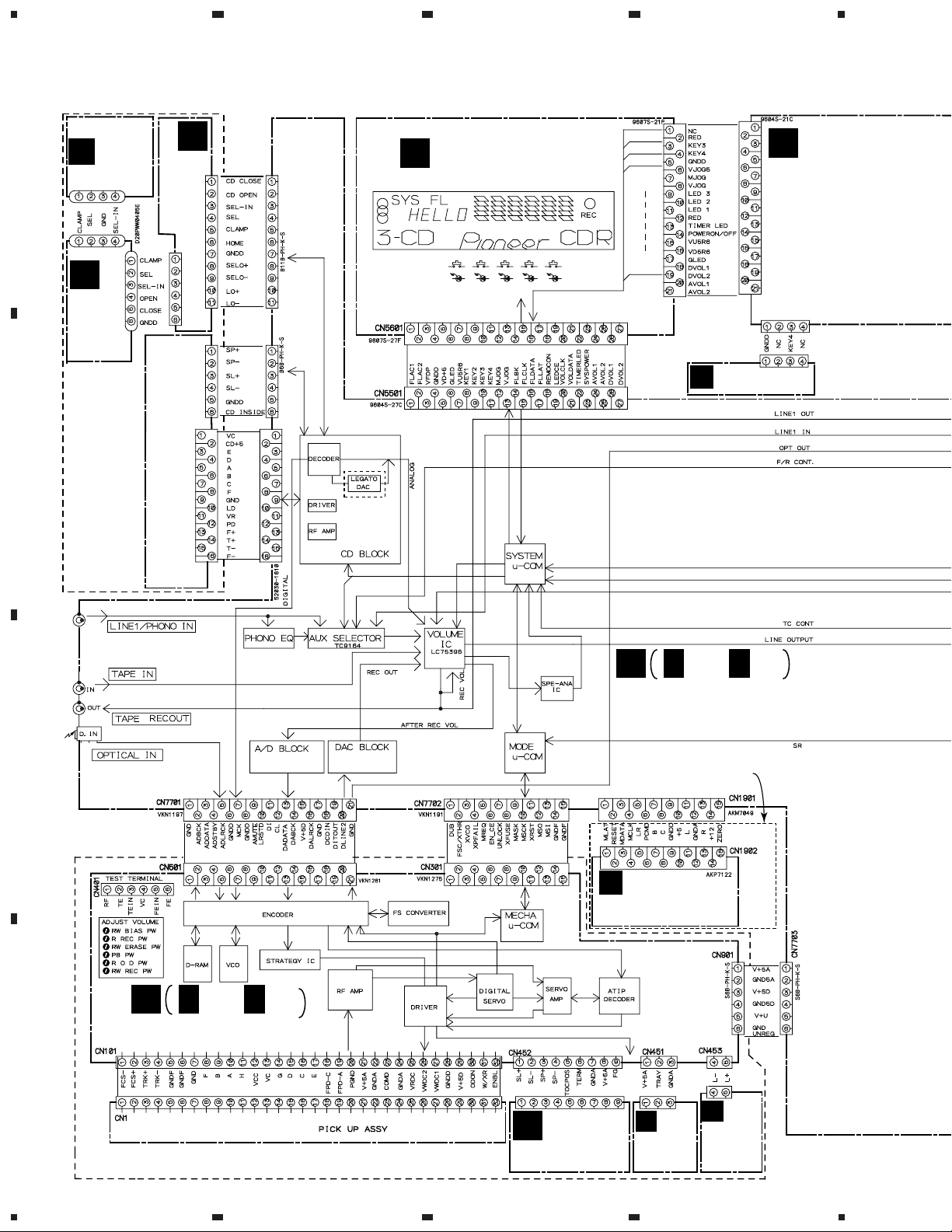
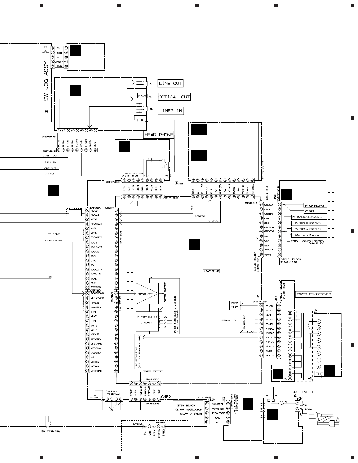
3.3 OVERALL WIRING DIAGRAM
SELECT
UNIT
A
F
(AWU7433)
J8502
G
J8503
CN8501
H
(AWU7431)
MOTOR UNIT
CN8003
CN1302
PG11KK-G20
DISPLAY ASSY
K
(AWU7461)
CN5901
UNIT
LOADING
(AWU7432)
B
MECHA
(AXA 7077)
CN8002
PICKU UNIT
(KSM213CCM)
ADE7051
CN1301
ADD7178
ADD7203
MY:Only
CN5951
ADD7202
CN5953
CN5954
CDR SW ASSY
M
(AWU7517)
L
(AWU7466)
SW JOG ASSY
3 CD MICRO CHANGER
CN1101
I 1/4- I 4/4
I
AF ASSY
(XR-MR7/MY : AWU7460)
(XR-MR7/KU/CA : AWU7448)
MY:LEGATO
C
ADD7200
KU/CA:NORMAL
ADD7201
XR-MR7/MY Only
V
LEGATO ASSY
(AWU7525)
B 1/5- B 5/5
B
CD-R CORE ASSY
(PYY1273)
D
PDD1195
CD-R
(PEA1351)
C
(PWZ3759)
SERVO
MECHA
CN601
CN501
D
LOADING
A ASSY
(PWZ3760)
E
ADE7055
CN551
B ASSY
LOADING
(PWZ3761)
18
1234
5
678
XR-MR7
Note : When ordering service parts, be sure to refer to "EXPLODED VIEWS and P AR TS LIST" or "PCB PARTS LIST".
CN5952
CN5403
CN3201
ADD7204
I
CN5962
N
(AWU7467)
O
ADD7205
AF ASSY
MY:Only
RDS
CDR LED
ASSY
FRONT LINE
ASSY
(MY : AWU7450)
FRONT LINE
ASSY
(KU/CA : AWU7438)
P
J3901
H. P ASSY
(AWU7453)
CN3101
FM/AM TUNER
AA
AB
MODULE
(MY : AXQ7068)
FM/AM TUNER
MODULE
(KU/CA : AXQ7065)
CN6201
CN6001
CN5001
REGULATOR
ASSY
U
(AWU7468)
A
B
AMP ASSY
J
(MY : AWU7464)
(KU/CA : AWU7555)
T1
CN11
S
CN3002
Q
SUB TRANS
ASSY
(MY : AWU7471)
(KU/CA:AWU7459)
SYSTEM CONNECTOR
FOR CT-J7
5
6
XR-MR7/MY Only
7
R
AC IN/OUT
ASSY
(MY:AWU7470)
(KU/CA:AWU7458)
(MY : ATS7271)
(KU/CA : ATS7272)
PRIMAR ASSY
(MY : AWU7469)
SECONDARY ASSY(AWU7451)
T
MY :
50/60Hz AC220-230V
KU/CA :
60Hz AC120V
AC POWER CORD
MY : ADG1127
KU/CA : ADG7021
19
8
C
(KU/CA : AWU7457)
D
1
23
XR-MR7
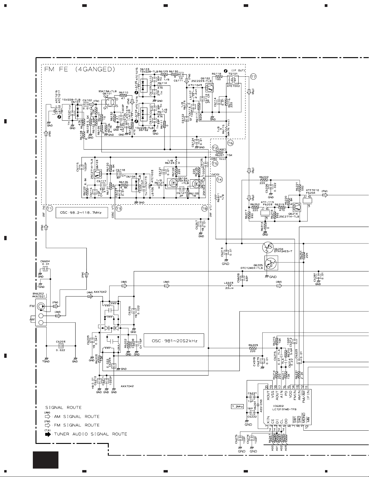
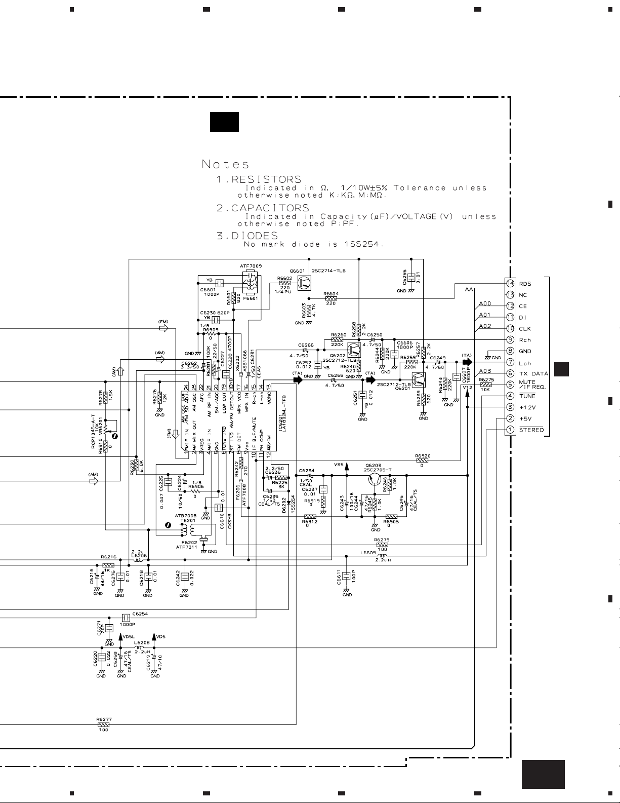
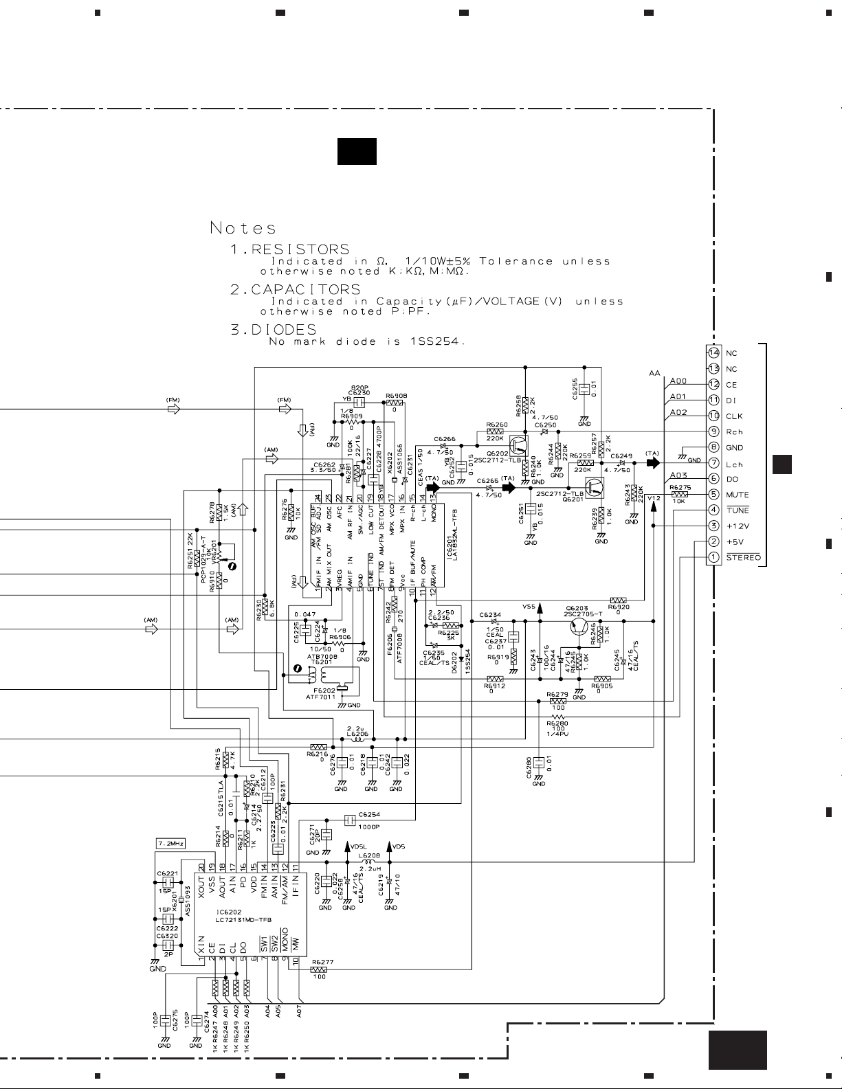
3.4 FM/AM TUNER MODULE (For MY Type)
A
RF AMP
OSC
B
4
MIX AMP
BUFFER
IF AMP
FM +B SW
C
AM RF TUNING BLOCK
D
20
AA
1234
PLL
5
678
XR-MR7
A
FM/AM TUNER MODULE
AA
(AXQ7068)
B
AF AMP
REGULATOR
CN6001
J
AF AMP
CN6201
KP200IA14L
C
D
AA
5
6
7
8
21
1
23
XR-MR7
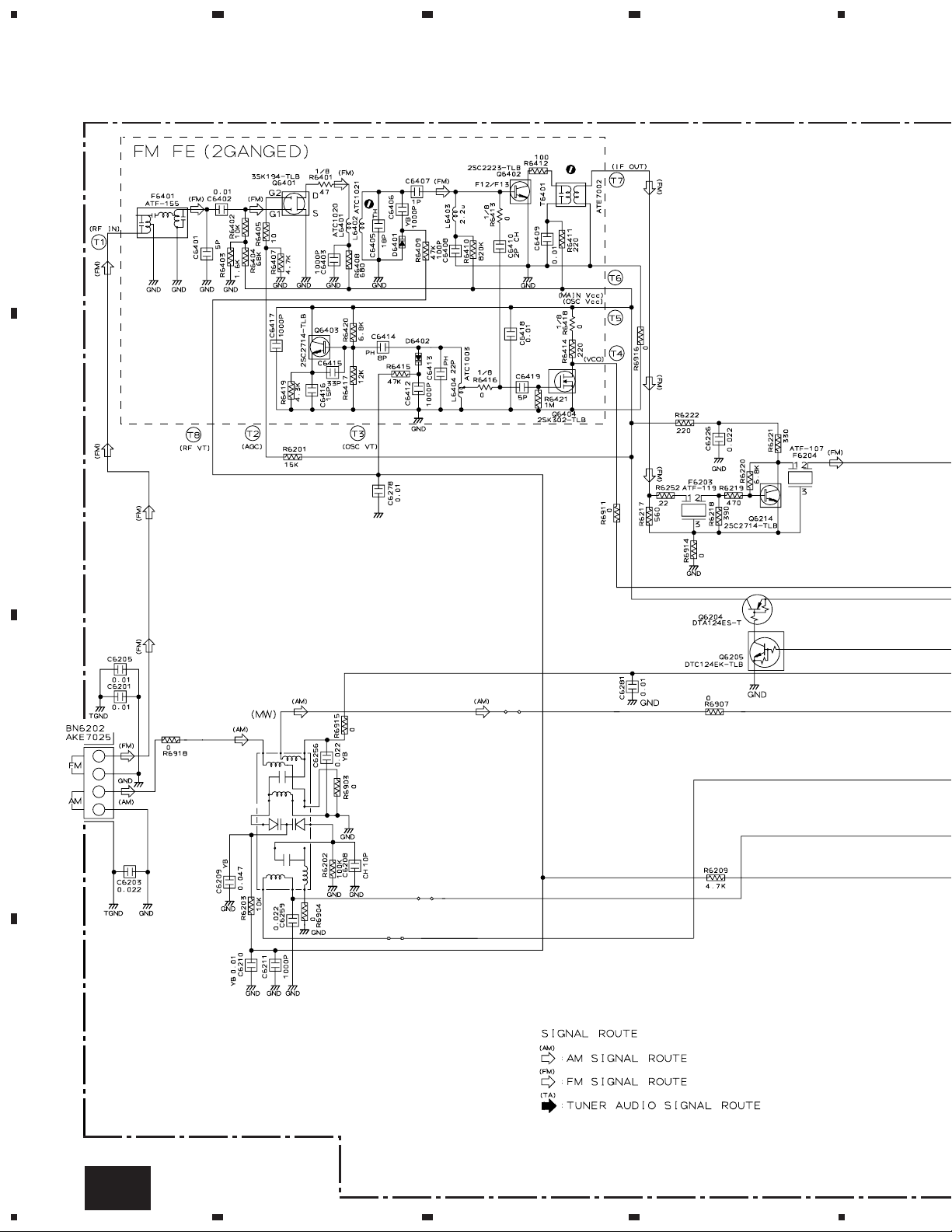
3.5 FM/AM TUNER MODULE (For KU/CA Type)
4
A
B
RF AMP
1T378A
OSC
1T378A
MIX AMP
BUFFER
IF AMP
FM +B SW
C
MW RF TUNING BLOCK
AKX7041
D
22
AB
1234
5
678
XR-MR7
FM/AM TUNER MODULE
AB
(AXQ7065)
AF AMP
A
B
CN6001
J
AF AMP
PLL
REGULATOR
CN6201
KP200IA14L
C
D
AB
5
6
7
8
23
1
XR-MR7
3.6 CD-R CORE ASSY (1/5)
23
4
CD-R CORE ASSY (PYY1273)
1/5
• MECHA. CONTROL µCOM BLOCK
B
5/5
B
B
2/5
A
B
ATIP DECODER
C
3/5
B
D
24
1/5
B
1234
5
8 bit LATCH
678
XR-MR7
A
4/5
B
B
8 9 10 11 12
MECHA µ-COM
CN301
L302,L305-L309,
L311-L315,L318,L319 :OTL1040
I
CN7702
EEPROM
IC303
PYY1196
(BR93LC46F)
C
D
1 2 3 4 5 6 7
1/5
5
6
7
B
8
25
1
23
XR-MR7
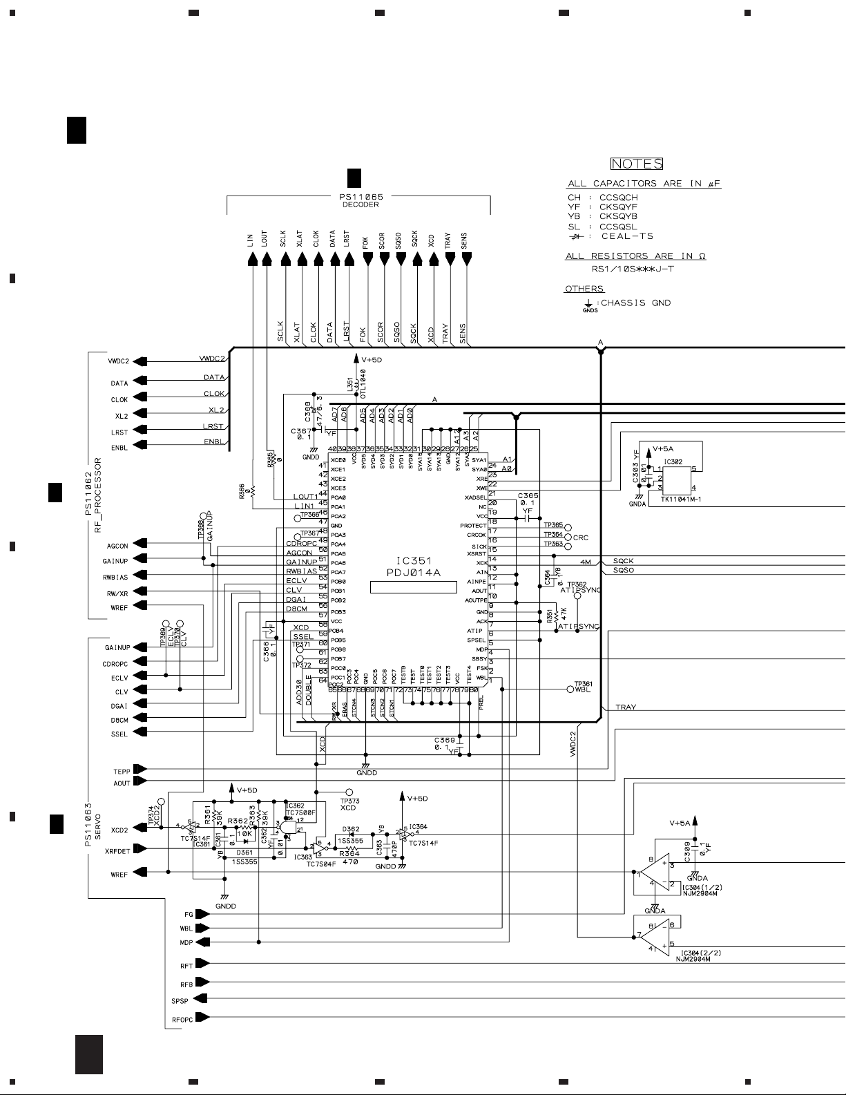
3.7 CD-R CORE ASSY(2/5) and CD-R PICKUP
4
A
B
CD-R PICKUP
(PEA1351)
B
CD-R CORE ASSY (PYY1273)
2/5
• RF PROCESSOR BLOCK
CN101
CN1
7
8
MULTI PLEXER
C
(REC)
(REC)
D
26
2/5
B
1234
(REC)
(REC)
(REC)
(REC)
MULTI PLEXER
(REC)
(REC)
4
CN102
3
5
678
XR-MR7
: RF SIGNAL ROUTE
(REC)
: AUDIO SIGNAL ROUTE (REC)
3/5
B
1
2
5
B
3/5
A
B
(REC)
(REC)
RF PROCESSOR
(REC)
6
(REC)
(REC)
(REC)
B
B
B
3/5
C
1/5
4/5
D
2/5
B
5
6
7
8
27
1
XR-MR7
3.8 CD-R CORE ASSY (3/5)
23
4
B
A
B
CD-R CORE ASSY (PYY1273)
3/5
• SERVO BLOCK
2/5
B
1/5
B
2
5/5
B
C
2/5
B
D
28
3/5
B
1234
5
678
XR-MR7
A
1/5
B
4/5
B
2/5
MULTI PLEXER
B
B
C
1/5
B
CDR SERVO AMP
1
D
3/5
B
5
6
7
8
29
1
M
XR-MR7
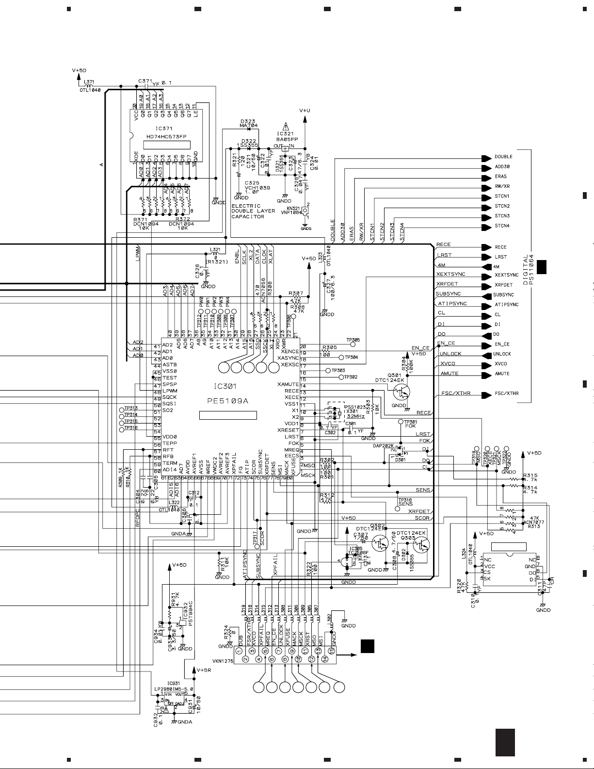
3.9 CD-R CORE ASSY (4/5)
23
4
A
3/5
B
B
B
CD-R CORE ASSY (PYY1273)
4/5
• DIGITAL BLOCK
(REC)
D-RA
VCO
(REC)
13
EFM ENCODER IC
2/5
B
C
D
(REC)
(REC)
(REC)
17
(REC)
18
(REC)
15
16
14
(REC)
(REC)
STRATEGY
CONTROL
(REC)
(DI1)
(DI2)
30
1/5
4/5
B
1234
B

D-RAM
5
678
XR-MR7
: AUDIO SIGNAL ROUTE
(REC)
: REC SIGNAL (after A/D)
(PB)
: PB OUT (before D/A)
(DI1)
: DIGITAL INPUT1
(DI2)
: DIGITAL INPUT2
(DO)
: DIGITAL OUT
: The power supply is shown with the marked box.
A
(DO)
16.9344MHz
(REC)
FS CONVERTER
(PB)
(DO)
(REC)
(PB)
(REC)
(PB)
(REC)
VCO
B
CN501
(REC)
(REC)
(PB)
(DI1)
(D0)
(DI2)
(PB)(PB)
1
2
3
4
12
5
6
7
8
9
10
11
C
I
CN7701
B
5/5
MULTI PLEXER
5
6
L511-L513,L515-L518,
L522,L524,L526 : OTL1040
F510,F514,F520
F521,F527 : VTH1097
7
B
4/5
8
D
31

1
23
4
XR-MR7
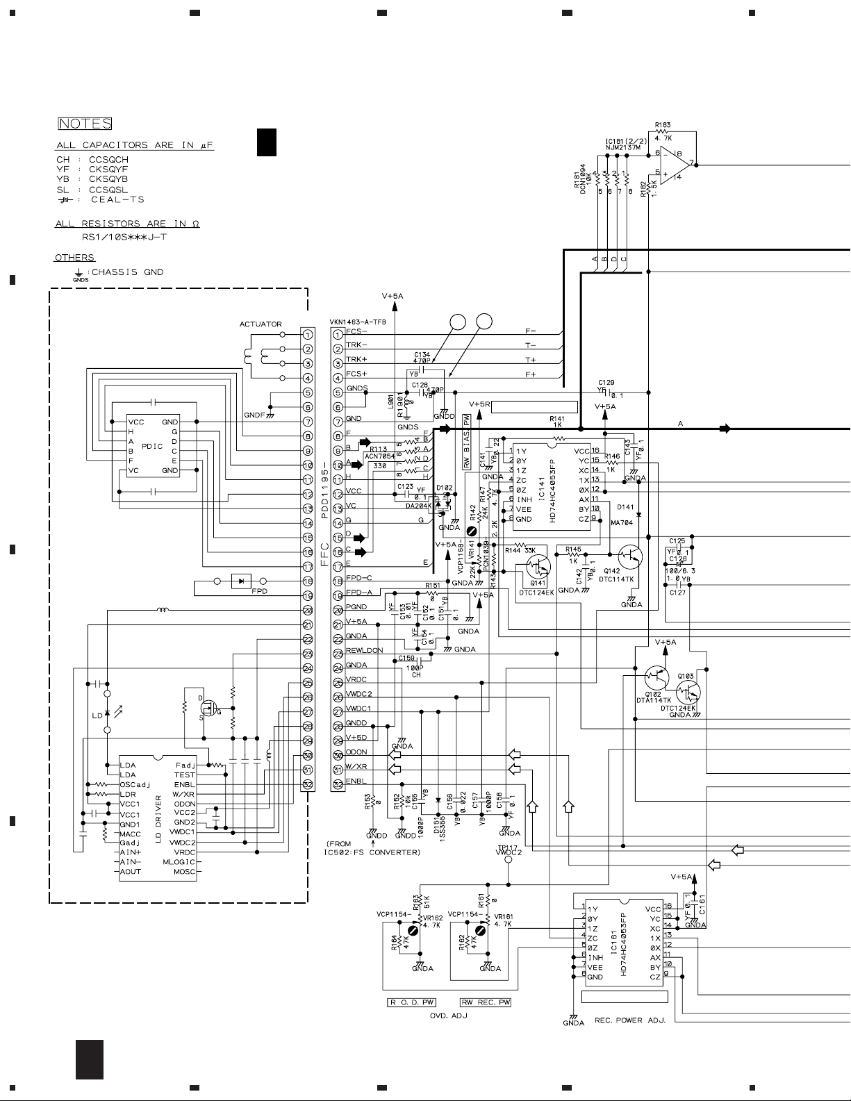
3.10 CD-R CORE ASSY(5/5), SERVO MECHANISM, LOADING A and LOADING
B ASSYS
A
3/5
B
B
CN453
CN451
CN452
1 2
B
CD-R CORE ASSY (PYY1273)
5/5
• DECODER BLOCK
5ch ACTUATOR DRIVER
3
C
CN501
S501
LOADING A
D
ASSY (PWZ3760)
LOADING B
E
ASSY (PWZ3761)
CN551
CARRIAGE MOTOR
ASSY (SLIDER)
CN601
D
PEA1350
DC MOTOR ASSY
(SPINDLE)
PEA1235
S601
SERVO MECHANISM
C
ASSY (PWZ3759)
LOADING MOTOR
ASSY
VXX2505
PC651
NJL5803K-F1
J601
B
2/5
32
5/5
B
1234
C
D
E

5
678
XR-MR7
2/5
B
B
5
4
A
1/5
B
CD DECODER
CN901
4/5
B
CN7703
I
C
: RF SIGNAL ROUTE
: AUDIO SIGNAL ROUTE
: The power supply is shown with the marked box.
5
6
D
5/5
B
7
8
33

XR-MR7
VOLTAGES and WAVEFORMS
CD-R CORE ASSY
1/5
B
Media Pickup Position
12cm Inner 0V 0V
12cm Outer 5V 0V
CD
8cm Inner 0V 0V
8cm Outer 5V 0V
12cm Inner 5V 0V
CD-R
CD-RW
12cm Outer 5V 0V
8cm Inner 0V 5V
8cm Outer 5V 5V
at FS = 44 kHz
(at FS Converter through)
FSR/XTHR
(CN301-pin 2)
at DIGITAL LOCK at DIGITAL UNLOCK
XVCO
(CN301-pin3)
UNLOCK
(CN301-pin7)
XPFAIL
(CN301-pin4)
XRST
(CN301-pin11)
0V 5V
0V 5V
0V 5V
5V
5V
DGAI
(IC351-pin56)
D8CM
(IC351-pin57)
Others
−
−
Note :
The encircled numbers denote measuring point in the schematic diagram.
1/5
CD-R CORE ASSY
B
CN301 - pin 5 (MREQ)
1
V: 0.2V/div.(10 : 1) H: 5msec/div.
(STOP)
CN301 - pin 6 (EN_CE)
2
V: 0.2V/div.(10 : 1) H: 5msec/div.
(STOP)
CN301 - pin 8 (XFUSE)
3
V: 0.2V/div.(10 : 1) H: 5msec/div.
(STOP)
CN301 - pin 13 (MSI)
7
V: 0.2V/div.(10 : 1) H: 5msec/div.
(STOP)
IC301 - pin 28 (SCLK)
8
V: 2V/div. H: 2µsec/div.
(Disck Loading)
IC301 - pin 27 (XL2)
9
V: 0.2V/div.(10 : 1) H: 5msec/div.
(STOP)
CD-R CORE ASSY
3/5
B
Operating
Mode
CLV
(IC201-pin13)
ECLV
(IC201-pin14)
STOP 0V 0V
CAV 0V 5V
CLV 5V 0V
ECLV 5V 5V
CD-R CORE ASSY
4/5
B
A/D Converter used
ADSTBY
(CN501-pin4)
AMUTE
(CN501-pin9)
LRSTD
(CN501-pin10)
at Analog REC Pause
or REC
0V 5V
at MUTE ON
(Audio Signal Not Output)
5V 0V
5V −
Others
at MUTE OFF
(Audio Signal Output)
CN301 - pin 9 (MACK)
4
V: 0.2V/div.(10 : 1) H: 5msec/div.
(STOP)
CN301 - pin 10 (MSCK)
5
V: 0.2V/div.(10 : 1) H: 0.5µsec/div.
(PLAY)
CN301 - pin 12 (MSO)
6
V: 0.2V/div.(10 : 1) H: 5msec/div.
(STOP)
IC301 - pin 26 (DATA)
10
V: 0.2V/div.(10 : 1) H: 5msec/div.
(STOP)
IC301 - pin 25 (CLOK)
11
V: 0.2V/div.(10 : 1) H: 5msec/div.
(STOP)
IC301 - pin 24 (XLAT)
12
V: 0.2V/div.(10 : 1) H: 5msec/div.
(STOP)
34

XR-MR7
CD-R CORE ASSY CD-R CORE ASSY
2/5
B
CN102 - pin 1 (RF)
1
V: 20mV/div.(10 : 1) H: 0.5µsec/div.
(PLAY)
CN102 - pin 3 (MPP)
2
V: 10mV/div.(10 : 1) H: 2msec/div.
(PLAY)
CN102 - pin 4 (TE)
3
V: 5mV/div.(10 : 1) H: 2msec/div.
(PLAY)
TP113 (RFAC)
5
V: 0.2V/div.(10 : 1) H: 0.2µsec/div.
(PLAY)
IC101 - pin 22 (ATFG)
6
V: 0.2V/div. H: 20µsec/div.
(REC)
CN101 - pin 3 (TRK +)
7
V: 0.2V/div.(10 : 1) H: 5msec/div.
(STOP)
3/5
B
TP210 (FG)
1
V: 0.2V/div.(10 : 1) H: 1msec/div.
(PLAY)
Foot of R212 (SPDL)
2
V: 20mV/div. H: 2msec/div.
(PLAY)
CN102 - pin 6 (FE)
4
V: 5mV/div.(10 : 1) H: 2msec/div.
(PLAY)
CN101 - pin 4 (FCS +)
8
V: 0.2V/div.(10 : 1) H: 5msec/div.
(STOP)
35

XR-MR7
CD-R CORE ASSY CD-R CORE ASSY
4/5
B
CN501 - pin 2 (ADBCK)
1
V: 0.2V/div.(10 : 1) H: 0.2µsec/div.
(STOP)
CN501 - pin 3 (ADDATA)
2
V: 0.2V/div.(10 : 1) H: 0.2µsec/div.
(REC)
CN501 - pin 5 (ADLRCK)
3
V: 0.2V/div.(10 : 1) H: 10µsec/div.
(STOP)
CN501 - pin 14 (DABCK)
7
V: 0.2V/div.(10 : 1) H: 0.2µsec/div.
(STOP)
CN501 - pin 16 (DALRCK)
8
V: 0.2V/div.(10 : 1) H: 10µsec/div.
(STOP)
CN501 - pin 18 (DIN1)
9
V: 0.2V/div.(10 : 1) H: 0.2µsec/div.
(REC_OPTICAL)
IC501 - pin 88 (EFM)
13
V: 0.2V/div.(10 : 1) H: 0.5µsec/div.
(REC)
IC431 - pin 6 (17M)
14
V: 0.2V/div.(10 : 1) H: 50msec/div.
(REC)
IC431 - pin 25 (ODON)
15
V: 0.2V/div.(10 : 1) H: 0.1µsec/div.
(REC)
5/5
B
CN452 - pin 2 (SL +)
1
V: 0.2V/div.(10 : 1) H: 5msec/div.
(PLAY)
CN452 - pin 3 (SP +)
2
V: 0.2V/div.(10 : 1) H: 5msec/div.
(PLAY)
CN452 - pin 9 (FG)
3
V: 0.2V/div.(10 : 1) H: 1msec/div.
CN501 - pin 7 (MCK)
4
V: 0.1V/div.(10 : 1) H: 50msec/div.
(STOP)
CN501 - pin 12 (CL)
5
V: 0.2V/div.(10 : 1) H: 0.5µsec/div.
(STOP)
CN501 - pin 13 (DADATA)
6
V: 0.2V/div.(10 : 1) H: 0.5µsec/div.
(PLAY)
CN501 - pin 19 (DITOUT)
10
V: 0.2V/div.(10 : 1) H: 0.2µsec/div.
(STOP)
CN501 - pin 20 (DIN2)
11
V: 0.2V/div.(10 : 1) H: 0.2µsec/div.
(REC_Coaxial)
CN501 - pin 11 (DI)
12
V: 0.2V/div.(10 : 1) H: 5msec/div.
(STOP)
IC431 - pin 29 (WLDON)
16
V: 0.2V/div.(10 : 1) H: 1msec/div.
(REC)
IC431 - pin 34 (REWLDON)
17
V: 0.2V/div.(10 : 1) H: 1msec/div.
(REC)
TP503 (W/XR)
18
V: 0.2V/div.(10 : 1) H: 1msec/div.
(REC)
IC401 - pin 25 (MDP)
4
V: 0.2V/div.(10 : 1) H: 5µsec/div.
(PLAY)
IC401 - pin 25 (MDP)
4
V: 0.2V/div.(10 : 1) H: 5µsec/div.
(REC)
IC401 - pin 20 (MIRR)
5
V: 0.2V/div.(10 : 1) H: 20µsec/div.
(REC_CD-RW)
36

1
234
3.10 MOTOR, LOADING, SELECT and PICKUP UNITS
SELECT UNIT
F
(AWU7433)
MOTOR UNIT (AWU7431)
H
J101
J101
XR-MR7
(F)
: FOCUS SERVO LOOP LINE
(T)
: TRACKING SERVO LOOP LINE
(S)
: SPINDLE SERVO LOOP LINE
(C)
: CARRIAGE SERVO LOOP LINE
(L)
: LOADING SERVO LOOP LINE
CN101
S11B-PH-K-S
A
CN1302
2/4
I
B
LOADING UNIT (AWU7432)
G
PICKUP UNIT
(KSM213CCM)
J102
J102
(S)
(S)
(S)
(S)
(C)
(C)
(L)
(L)
CN1301
(L)
(L)
(C)
(C)
2/4
I
C
CN1101
2/4
I
(F)
(T)
(F)
1
2
3
(F)
(T)
(T)(T)
(F)
F
G
H
4
D
37

1
23
XR-MR7
3.11 AF (1/4) and H.P ASSYS
4
C3205
470p
A
(L1)
LINE1 / PHONO IN
KU/CA :220p
MY : 330 p
C3203
KU/CA :220p
MY : 330 p
(REC)
(L1)
470p
C3204
470p
(L2)
R3299
(REC)
(L1)
(REC)
µ
470p
C3206
B
CN5403
O
4.952V
(Lin)
(Lin)
(L1)
(L2)
(CD-R) (CD-R)
(TX)
(CD)
(REC)
11.738V
Separator
(Lin) (Lin)
(REC)
(Lin)
(TX)
(REC)
(CD)
(CD)
-5.667V
10.132V
4.954V
C
(CD)
(TX) (TX)
(CD)
-5.673V
(REC)(REC)
(TX)
1.226V
(REC)(REC)
(TX)
16.242V
I 3/4
0.615V
-0.002V
D
(CD-R) (CD-R) (CD-R)
8.165V
-0.002V
5.532V
38
I
I 3/4
1/4
Q
J13
1234

5
SIGNAL ROUTE
(CD)
: CD AUDIO SIGNAL
(L1)
: LINE 1 SIGNAL
(L2)
: LINE 2 SIGNAL
(MAIN)
: MAIN OUT SIGNAL
678
XR-MR7
(CDR)
: CD-R AUDIO SIGNAL
(TX)
: TUNER AUDIO SIGNAL
(Lin)
: LINE IN SIGNAL
(REC)
: RECORDING SIGNAL
I 1/4
AF ASSY(1/4)
(MY : AWU7460)
(KU/CA : AWU7448)
I 4/4
A
(Lin)
(TX)
(CD-R)
10.216V
(REC)
10.977V
(CD)
11.739V
(REC)
(REC)
(1/2)
(REC)
(REC)
(REC)
(REC)(REC)
I 4/4
MY:Only
To CT-J7
B
MY:Only
(MAIN)
MY:Only
(MAIN)
-5.674V
(TX)
CN6002
J
J
CN3002
(MAIN)
(MAIN)
(MAIN)
C
(2/2)
(MAIN)
(MAIN) (MAIN)
J
(REC)(REC)
O
J5401
D
(TX)
(MAIN)
(MAIN)
CN3101
4.954V
11.742V
CN3001
J
L501
4.940V
VTL1094
4.913V
P
4.953V
8.775V
4.939V
H.P ASSY
(AWU7453)
5.948V
: The power supply is shown with the marked box.
1/4
I
5
6
7
P
8
39

1
XR-MR7
3.12 AF (2/4) and LEGATO ASSYS
A
B
23
5.948V
4.868V
(SM)
(SM)
(SM)(SM)
(SM)
(CM)
4
4.888V
(SM)
(CM)
(CM)
(TS)
(TS)
(FS)
(FS)
2.444V
(F)
(CM)
(CM)
(F)
5.681V
4.889V
1.629mV
0.087V
IC1101- Pin 16 :
2
TEST MODE,
Tracking Open (TRER)
H : 5msec/div
VC : IC1101- Pin22
2.44V
(CD)
To CD MECHA.
C
(L)
(S)
(C)
To CD MECHA.
5.948V
1.0Vp-p
VC
(CD)
(T)
(CD)
(F)
(T)
(T)
2
(T)
1
D
40
To P.U Assy
2/4
I
(F)
(T)
(T)
(F)
IC1101- Pin 13:
1
PLAY MODE (RF)
H : 500nsec/div
1.0Vp-p
VC
(F)
1234

5
678
XR-MR7
I 2/4
KU/CA:Only
(SM)
(CM)
(CM)
(TS)
(TS)
(FS)
(FS)
(F)
100p
2.120V
(PC)
4.870V
KU/CA:Only
MY:Only
4.885V
AF ASSY(2/4)
(MY : AWU7460)
(KU/CA : AWU7448)
4.885V
4.881V
MY:Only
W267
KU/CA:Only
W268
KU/CA:Only
(CD)
(CD)
I 4/4
4.936V
11.740V
(D)(D)
MY:Only
(CD)
–5.673V
A
I 1/4
B
(T)
(T)
(CD)
(CD)
LEGATO ASSY
V
MY:Only
4.887V
0.163V
MY:Only
4.633V
SIGNAL ROUTE
(CD)
: CD AUDIO SIGNAL ROUTE
(FS)
: FOCUS SERVO LOOP LINE
(TS)
: TRACKING SERVO LOOP LINE
(AWU7525)
0.164V
(SM)
(CM)
(LM)
4.847V
4.885V
(CD)
: SPINDLE MOTOR ROUTE
: CARRIAGE MOTOR ROUTE
: LOADING MOTOR ROUTE
(PC)
MY:Only
C
(CD)
(PC)
6.142V
(CD)
D
: The power supply is shown
with the marked box.
2/4
5
6
7
I
V
8
41

1
XR-MR7
3.13 AF ASSY (3/4)
23
4
I 3/4
A
6.247V
AF ASSY(3/4)
(MY : AWU7460)
(KU/CA : AWU7448)
6.247V
6.247V
11.735V
(CDR)(CDR)
(CDR)(CDR)
4.934V
R7406
KU/CA:220
R7407,R7408
KU/CA : 0
MY:100
KU/CA:PCM1716E
MY:PE8001A
KU/CA:STBY
MY:100
C7412
MY:100p
4.935V
4.760V
(CDR)(CDR)
17.25mV
B
3.365mV
I 1/4
4.932V
(REC) (REC)
4.688V
2.096V
(REC)
100p
4.908V
C
(REC)
2.09V
4.688V
2.096V
R7305
2.99V
VTL1096
MY:1.8k
KU/CA:560
D
42
3/4
I
1234

5
678
XR-MR7
SIGNAL ROUTE
(CDR)
: CD-R AUDIO SIGNAL
(REC)
: RECORDING SIGNAL
V+5D
4.951V
4.939V
R7492
KU/CA:330
MY : 1.8k
4.939V
R7451
KU/CA:560
MY : 0
17.40mV
4.585V
57.75mV
2.167V
VTL1096
L7454
2.002V
16.10mV
A
I 4/4
VTL1096
CN501
B
B
VTL1105
470
I 1/4
C
CN301
B
VTL1096
4.906V
4.949V
CN901
8.781V
B
D
I 1/4
3/4
I
5
6
7
8
43

1
23
XR-MR7
3.14 AF (4/4), FRONT LINE, CDR SW and CDR LED ASSYS
A
I 1/4
4.633V
5.525V
4.632V
4
B
4.952V
5.505V
FRONT LINE ASSY
O
(MY:AWU7450, KU/CA:AWU7438)
C
(L2)
L5409
L5404
VTL1096
220p
VTL1096
220p
C5413
L5407
1000p
VTL1096
(L2)
(L2)
(L2)
(REC)
I 1/4
CN3201
P
1000p
J5401
DB011ND0
D
44
4/4
I
1234
C5414
L5406
VTL1096
L5408
L5405
(REC)
VTL1096
O
VTL1096
220p220p
(REC)
SIGNAL ROUTE
(L2)
: LINE 2 SIGNAL
(REC)
: RECORDING SIGNAL

5
678
XR-MR7
AC:7.704V
I 4/4
4.632V
AF ASSY(4/4)
(MY : AWU7460)
(KU/CA : AWU7448)
4.707V
5.051V
5.524V
MY:Only
A
37.30V
CN5601
K
B
M
: The power supply is shown
with the marked box.
5
CDR SW ASSY
(AWU7517)
L
CN5953
6
CDR LED ASSY
N
(AWU7467)
7
CN5952
L
I
4/4
M
N
8
C
D
45

A
1
23
4
XR-MR7
3.15 AMP, REG, SECONDARY, PRIMARY, SUBTRANS and AC IN/OUT ASSYS
23.083V
100p
MY:Only
(MAIN)
100p
-23.035V
-39.32V
39.41V
39.44V
(MAIN)
-39.39V
B
C
AKP1121 (MY)
AKP1122 (KU/CA)
D
VNF1084
KU/CA
TYPE
Only
POWER
TRANSFORMER
(MY:AWU7469)
PRIMARY ASSY
(KU/CA:AWU7457)
T
FU 2
KU/CA : AEK1082 4A/125V
MY : AEK1057 T2.0AL250V
FU 2
CN1
MY :
TYPE
Only
AKP1034
AC IN/OUT
R
(KU/CA:AWU7458)
ASSY
(MY:AWU7470)
SECONDARY
S
ASSY
(AWU7451)
FU 1
ATT7064 (MY)
ATT7063 (KU/CA)
L 1
ATF–151
SUB TRANS
Q
ASSY
(MY:AWU7471)
(KU/CA:AWU7459)
4.899V
FU 1
MY : AEK1058 T2.5AL250V
KU/CA : AEK1083 5A/125V
6.69V
(MAIN)
36.97V
6.69V
21.68V
14.65V
CN21
I
CAUTION : FOR CONTINUED PROTECTION AGAINST
11.76V
RISK OF FIRE. REPLACE ONLY WITH SAME
TYPE NO. 491004 FOR IC14, 4910007 FOR
IC15, IC18, IC19 MFD. BY LITTELFUSE INC.
(MAIN)
46
Q
1234
RJ
S
T

(MAIN)
5
678
XR-MR7
SIGNAL ROUTE
(MAIN)
: MAIN OUT SIGNAL
(TX)
: TUNER AUDIO SIGNAL
R6099
KU/CA:1.2k
MY : 0
–5.675V
A
J
AMP ASSY
(MY : AWU7464)
(KU/CA : AWU7555)
(MAIN)
(MAIN)
(MAIN)
CN6201 (MY TYPE)
AA
CN6201 (KU/CA TYPE)
AB
(TX)
(TX)
(MAIN)
4.944V
4.898V
(MAIN)
14.58V
4.96V
(MAIN)
14.58V
4.97V
(MAIN)
(TX) (TX)
(MAIN)
(MAIN)
12.32V
11.738V
4.94V
37.23V
37.29V
11.742V
4.954V
4.915V
4.954V
8.777V
I
CN6003
I
CN3102
B
C
14.63V
14.63V
4.95V
5.95V
14.56V
REGULATOR
U
ASSY
(AWU7468)
: The power supply is shown with the marked box.
• NOTE FOR FUSE REPLACEMENT
CAUTION -
5
FOR CONTINUED PROTECTION AGAINST RISK OF FIRE.
REPLACE WITH SAME TYPE AND RATINGS ONLY.
6
4.95V
8.73V
(MAIN)
P
J3901
7
4.898V
4.94V
(MAIN)
5.948V
I
CN521
J U
8
D
47

1
XR-MR7
3.16 DISPLAY and SW JOG ASSYS
DISPLAY ASSY
A
B
K
(AWU7461)
23
36.6V
4
4.96V
C
CN5501
I
4.95V
D
48
K
1234
DISPLAY ASSY
S5901 : 1 0
S5902 : 2 0
S5903 : 3 0
S5904 : LINE1/PHONO
S5905 : LINE2
S5906 : 1
S5907 : 2
S5908 : 3
CD
CD SELECT
S5909 : CD-R
S5914 : FM/AM
S5915 : TAPE
S5916 : 1 (–)
S5917 : 7 (STOP)
S5918 : 6 (PLAY/PAUSE)
S5919 : ¡ (+)
S5920 : SFC (DEMO)
S5921 : DISPLAY

5
678
XR-MR7
A
SW JOG ASSY
L
(AWU7466)
B
POWER REC
REC/PLAY
ALL 1-TRACK RENTAL
C
SW & JOG ASSY
S5951 : TIMER/CLO.
S5952 : ENTER
S5953 : MENU
S5954 : FINALIZE
S5955 : ERASE
S5956 : P.BASS
S5957 : REC STOP
5
S5959 : RENTAL
S5960 : 1–TRACK
S5961 : ALL
S5962 : REC PLAY
S5963 : REC
S5964 : STANDBY/ON
S5965 : VOLUME JOG
6
CN5962
N
S5966 : MULTI JOG
S5969 : DIGTAL VOL
S5970 : ANALOG VOL
CN5954
M
K
7
L
8
49
D

1
23
XR-MR7
4. PCB CONNECTION DIAGRAM
NOTE FOR PCB DIAGRAMS :
A
1. Part numbers in PCB diagrams match those in the schematic
diagrams.
2. A comparison between the main parts of PCB and schematic
diagrams is shown below.
Symbol In PCB
Diagrams
BCE
BCE
D
Symbol In Schematic
Diagrams
BCEBCE
BCE
BCE
DGS
DGGSS
Part Name
Transistor
Transistor
with resistor
Field effect
transistor
Resistor array
3-terminal
regulator
4.1 FM/AM TUNER MODULE ( For MY Type )
FM/AM TUNER MODULE
B
AA
3. The parts mounted on this PCB include all necessary parts for
several destinations.
For further information for respective destinations, be sure to
check with the schematic diagram.
4. View point of PCB diagrams.
Connector
P.C.Board
Capacitor
Chip Part
SIDE A
SIDE B
CN6001
J
4
SIDE A
C
Q6204 Q6203
FM/AM TUNER MODULE
AA
VR6201
SIDE B
D
50
AA
Q6101
Q6501
Q6102 - Q6105 Q6205
Q6214
Q6601
Q6202
IC6202
Q6201
IC6201
(ANP7160-B)
1234

1
234
XR-MR7
4.2 FM/AM TUNER MODULE (For KU/CA Type)
FM/AM TUNER MODULE
AB
Q6204
CN6001
J
A
B
VR6201
Q6203
FM/AM TUNER MODULE
AB
Q6306
Q6304
Q6401
SIDE A
Q6402
Q6303Q6302 Q6301
Q6214
Q6403
Q6404
Q6205
Q6202 Q6201
IC6202
C
(ANP7159-B)
IC6201
D
SIDE B
AB
1
2
3
4
51

1
23
4
XR-MR7
4.2 CD-R CORE ASSY SIDE A
A
CD-R CORE ASSY
B
• This PCB is a four-layered board.
E
CN551
D
CN501
C
CN601
I
CN7703
B
I
CN7702
To
C
CD-R
PICKUP
I
CN7701
(PNP1465-B)
VR164
VR161 VR141 VR162 VR163 VR101
IC361-IC364 IC303 IC302 IC305IC931-IC933
D
IC351 IC371 IC301 IC304 IC503Q301
Q302 Q303 Q402 Q401 IC401 IC501 IC507 IC506IC352
IC451 IC201 IC502 IC509Q203 Q203IC251-IC254
Q201 IC101 Q142 IC562 IC431
52
B
1234

1
234
XR-MR7
SIDE B
CD-R CORE ASSY
B
• This PCB is a four-layered board.
A
B
Q551 Q202 IC255
IC505 IC508 IC181
Q102 IC561 IC141 IC161
Q103 Q141
1
2
C
(PNP1465-B)
D
B
3
4
53

1
XR-MR7
4.3 SERVO MECHA, LOADING A and LOADING B ASSYS
A
23
4
CARRIAGE
MOTOR
M
B
SPINDLE
MOTOR
SERVO
C
MECHANISM
ASSY
M
CN452
B
D
LOADING A
ASSY
SERVO
C
MECHANISM
ASSY
LOADING A
D
ASSY
C
CN451
B
LOADING B
LOADING B
E
ASSY
SIDE A SIDE B
D
54
C
D
1234
E
LOADING
MOTOR
M
B
CN453
(PNP1447-C)
E
ASSY

1
4.4 SELECT UNIT, LOADING UNIT and MOTOR UNIT
234
XR-MR7
SELECT
F
UNIT
A
B
MOTOR
H
UNIT
M
CN1302
I
M
LOADING
G
UNIT
(ANP7314-B)
C
(ANP7314-B)
(ANP7314-B)
SIDE A
D
1
2
3
F
G
H
4
55

XR-MR7
M
4.5 AF ASSY
A
B
1
AF ASSY
I
23
CN3002
J
B
CN901
CN3001
J
4
CD MECHA
CD
J13
Q
CN1902
V
C
D
56
I
1234

1
234
XR-MR7
CD MECHA
HA
CN6002
J
CD MECHA
CN5601
K
Q1342
Q1346
Q1341 Q1345
Q1101
IC21
Q21
Q22
SIDE A
A
B
B
1
CN501
B
CN301
C
CN5403
O
D
(ANP7320-D)
57
I
2
3
4

A
B
1
XR-MR7
AF ASSY
I
23
4
C
D
58
I
1234

1
234
XR-MR7
SIDE B
A
Q5752 Q5751 Q3125
Q1343 Q1346
Q1342
IC5751
Q1344 Q1341
Q1345
Q5501 Q1406
Q5505
IC1301
Q1405
IC1101
Q22 Q21
B
IC5501
Q5502
IC1201
Q1403
Q1402
Q1402
IC3131
Q1203
Q5503
Q1401
Q3143
Q7304
IC7502
IC7401
IC3031
IC7301
IC7501
Q4602
Q1404
Q1901
Q3142
Q5504
Q3141
Q3144
Q7510Q7509 Q1911Q1201
IC3101
IC3031
Q3122
IC3151
Q3121
Q4601
C
Q7231
Q7502 Q7232
IC7231
Q7236 Q7237
IC3081
D
(ANP7320-D)
59
I
1
2
3
4

1
23
XR-MR7
4.6 AMP, H.P and REGULATOR ASSYS
4
A
J
AMP ASSY
B
CN6201 (MY)
AA
CN6201 (KU/CA)
AB
C
IC3301
Q301
Q302
60
IC5003
J
1234
D
S
J11
I
IC12
IC301
CN521
IC5001 Q5001
CN3102
I
IC15
I
(ANP7321-D)
CN6003

1
234
XR-MR7
SIDE A
H.P ASSY
P
REGULATOR ASSY
U
IC503 IC502 IC501 IC504 IC505 Q502 Q501
O
J5401
To GND Chassis
(ANP7320-D)
A
B
C
(ANP7320-D)
D
P
1
2
3
U
4
61

1
REGULATOR ASSY
U
H.P ASSY
P
(ANP7320-D)
(ANP7320-D)
XR-MR7
23
4
A
B
SIDE B
C
D
62
P
U
1234

J
AMP ASSY
1
234
XR-MR7
SIDE B
A
B
C
(ANP7321-D)
Q5001
Q3612
1
Q322
IC5001
2
Q320
Q324 Q323
Q3611
Q3608
Q3605 Q3606 Q3607
3
Q3610
Q3609
Q3303
Q3302
Q3301
Q303
Q304
IC3301 Q301
Q302
IC5003
J
4
D
63

1
23
XR-MR7
4.7 AC IN/OUT, SUBTRANS, PRIMARY and SECONDARY ASSYS
AC IN/OUT
R
A
B
ASSY
AC IN AC OUT
SUBTRANS
Q
ASSY
4
SIDE A
I
CN21
(ANP7321-D)
PRIMARY
T
(ANP7321-D)
ASSY
C
(ANP7321-D)
POWER TRANSFORMER
SECONDARY
S
ASSY
D
64
Q
R
1234
S
T
IC19
IC18
J
IC14
CN11
(ANP7320-D)

1
234
XR-MR7
SIDE B
SUBTRANS
Q
ASSY
PRIMARY
T
ASSY
(ANP7321-D)
AC IN/OUT
R
ASSY
A
B
(ANP7321-D)
SECONDARY
S
ASSY
1
C
(ANP7321-D)
(ANP7320-D)
Q
2
3
R
S
T
4
65
D

1
23
4
XR-MR7
4.8 DISPLAY ASSY SIDE A
A
DISPLAY
K
CN5951
L
ASSY
B
Q5601
CN5501
I
C
D
(ANP7321-D)
66
K
1234

1
234
XR-MR7
SIDE B
DISPLAY
K
ASSY
A
Q5603
IC5602
B
IC5601
Q5602
IC5801
(ANP7321-D)
C
D
K
67
1
2
3
4

1
23
4
XR-MR7
4.9 SW JOG, CDR SW and CDR LED ASSYS SIDE A
A
SW JOG ASSY
L
CDR LED ASSY
N
(ANP7320-D)
B
CDR SW ASSY
M
(ANP7320-D)
C
D
68
(ANP7321-D)
L
M N
1234
CN5901
K

1
234
XR-MR7
SIDE B
SW JOG ASSY
L
CDR LED ASSY
N
CDR SW ASSY
M
A
(ANP7320-D)
B
Q5951
Q5952
(ANP7321-D)
(ANP7320-D)
C
D
1
2
3
L
M N
4
69

1
23
XR-MR7
4.10 FRONT LINE and LEGATO ASSYS
4
FRONT LINE ASSY
A
B
O
I
CN3201
(ANP7320-D)
FRONT LINE ASSY
O
Q3123
Q3124
LEGATO ASSY : MY Only
V
C
I
CN1901
D
(ANP7320-D)
LEGATO ASSY : MY Only
V
IC1902
IC1901
70
SIDE A
O
V
1234
SIDE B

Mark No. Description Part No.Mark No. Description Part No.
5. PCB PARTS LIST
NOTES:•Parts marked by "NSP" are generally unavailable because they are not in our Master Spare Parts List.
7 LIST OF WHOLE PCB ASSEMBLIES
The mark found on some component parts indicates the importance of the safety factor of the part.
•
Therefore, when replacing, be sure to use parts of identical designation.
When ordering resistors, first convert resistance values into code form as shown in the following examples.
•
Ex.1 When there are 2 effective digits (any digit apart from 0), such as 560 ohm and 47k ohm (tolerance is shown by J=5%,
and K=10%).
560 Ω→56 × 10
47k Ω→47 × 10
1
→ 561 ........................................................ RD1/4PU 5 6 1 J
3
→ 473 ........................................................ RD1/4PU 4 7 3 J
0.5 Ω→R50 .....................................................................................RN2H R 5 0 K
Ex.2 When there are 3 effective digits (such as in high precision metal film resistors).
5.62k Ω→ 562 × 10
1
→ 5621 ...................................................... RN1/4PC 5 6 2 1 F
1 Ω→1R0 .....................................................................................RS1P
1 R 0
XR-MR7
K
Mark
FM/AM TUNER MODULE AXQ7068 AXQ7065
CD-R CORE ASSY RYY1273 RYY1273
NSP MECHANISM ASSY PWX1570 PWX1570
NSP SERVO MECHANISM ASSY PWZ3759 PWZ3759
NSP LOADING A ASSY PWZ3760 PWZ3760
NSP LOADING B ASSY PWZ3761 PWZ3761
NSP 3CD UNIT AWM7473 AWM7473
MOTOR UNIT AWU7431 AWU7431
LOADING UNIT AWU7432 AWU7432
NSP SELECT UNIT AWU7433 AWU7433
NSP MAIN ASSY AWM7479 AWM7477
AF ASSY AWU7460 AWU7448
FRONT LINE ASSY AWU7450 AWU7438
H.P ASSY AWU7453 AWU7453
SECONDARY ASSY AWU7451 AWU7451
NSP CDR LED ASSY AWU7467 AWU7467
CDR SW ASSY AWU7517 AWU7517
LEGATO ASSY AWU7525 Not used
NSP COMPLEX ASSY AWM7480 AWM7478
AMP ASSY AWU7464 AWU7555
REG ASSY AWU7468 AWU7468
PRIMARY ASSY AWU7469 AWU7457
SUB TRANS ASSY AWU7471 AWU7459
AC IN/OUT ASSY AWU7470 AWU7458
DISPLAY ASSY AWU7461 AWU7461
SW JOG ASSY AWU7466 AWU7466
MY Type KU/CA Type
Part No.
RemarksSymbol and Description
71

XR-MR7
Mark No. Description Part No.Mark No. Description Part No.
7 CONTRAST OF PCB ASSEMBLIES
AF ASSY
I
AWU7460 and AWU7448 are constructed the same except for the following :
Mark Symbol and Description
IC5751
IC7401
Q1201,Q1911
Q1403,Q1404
Q1901
AWU7460 AWU7448
BU1923F
PE8001A
2SC2412K
Not used
DTA124EK
Part No.
Remarks
Not used
PCM1716E
Not used
DTA124EK
Not used
Q4601
Q5751
Q5752
L5751
C22
C1107
C1201,C1202
C1204
C2551- C2553,C7412
C3015
C3101- C3104
C3126,C3127
C3335- C3340
C3345- C3346
C4601
C5751, C5752
C5753,C5755
C5754
C5756
C5757
C5758
D5506
R1201
R1202
R1205
R1286,R1287
R1420,R1951,R3991,R5754,R5755
R1931
R2551- R2553
R2554
2SA1037K(RS)
2SA1037K
DTC143EK
LAU1R0J
CEAT470M25
CKSQYB103K50
Not used
CCSQCH101J50
CCSQCH101J50
CKSQYB473K25
CCSQCH331J50
CEAT2R2M50
CKSQYB104K25
ACG7041
CKSQYB104K25
CCSQCH270J50
CKSQYB103K50
CEAT330M16
CKSQYB561K50
CCSQCH271J50
CEAT100M50
1SS133
Not used
Not used
RS1/10S103J
Not used
RS1/10S0R0
RS1/10S103J
RS1/10S221J
RS1/10S472J
2SA1037K(QR)
Not used
Not used
Not used
CEAT470M35
CKSQYB104K25
CCSQCH150J50
Not uaed
Not used
CKSQYB104K25
CCSQCH221J50
CEAT100M50
Not used
Not used
CKSQYB103K50
Not used
Not used
Not used
Not used
Not uesd
Not used
Not used
RS1/10S331J
RS1/10S105J
Not used
RS1/10S221J
Not used
Not used
Not used
Not used
72
R3335- R3338
R5751
R5752
R5753
R5960
R5961
R7305
R7406- R7408
R7451
R7492
CN1901
CN2551
X1201 Crystal Resonator (16.9344MHz)
X5751 Crystal Resonator (4.332MHz)
RD1/10S100J
RS1/10S223J
RD1/10S222J
RS1/10S101J
RS1/10S473J
Not used
RS1/10S182J
RS1/10S101J
RS1/10S0R0J
RS1/10S182J
AKM7049
AKP7042
Not used
ASS7004
Not used
Not used
Not used
Not used
Not used
RS1/10S473J
RS1/10S561J
RS1/10S0R0J
RS1/10S561J
RS1/10S331J
Not used
Not used
PSS1008
Not used

Mark No. Description Part No.Mark No. Description Part No.
AC IN/OUT ASSY
R
AWU7470 and AWU7458 are constructed the same except for the following :
Mark Symbol and Description
CN 01
CN02
SUB TRANS ASSY
Q
AWU7471 and AWU7459 are constructed the same except for the following :
Mark Symbol and Description
KN01
R01
T02
AWU7470 AWU7458
AKP1121
AKP1034
AW7471 AWU7459
Not used
Not used
ATT7064
Part No.
Part No.
XR-MR7
Remarks
AKP1122
Not used
Remarks
VNF1084
RCN1080
ATT7063
AMP ASSY
J
AWU7464 and AWU7555 are constructed the same except for the following :
Mark Symbol and Description
Q304
Q320
C3305
C3317
R6099
FRONT LINE ASSY
O
AWU7450 and AWU74638are constructed the same except for the following :
Mark Symbol and Description
CN5403 52045-0945 HLEM9S-1
PRIMARY ASSY
T
AWU7464 AWU7555
2SA1037K (RS)
2SA1037K (RS)
CCSQCH101J50
CCSQCH101J50
RS1/10S0RJ
AWU7450 AWU7438
Part No.
2SA1037K(QR)
2SA1037K (QR)
Not used
Not used
RS1/10S1R2J
Part No.
Although AWU7469 and AWU7457 are different in part number, they consist of the same components.
Remarks
Remarks
73

XR-MR7
Mark No. Description Part No.Mark No. Description Part No.
PCB PARTS LIST FOR XR-MR7/MY UNLESS OTHERWISE NOTED
FM/AM TUNER MODULE (AXQ7068)
AA
SEMICONDUCTORS
IC6201 LA1832ML
IC6202 LC72131MD
Q6102 2SC2223
Q6203 2SC2705
Q6201,Q6202 2SC2712
Q6103,Q6214,Q6601 2SC2714
Q6104,Q6105 2SK302
Q6101 3SK194
Q6204 DTA124ES
Q6205 DTC124EK
D6202 1SS254
D6101-D6104 1SV228
C6244 CEAS470M16
C6249,C6250,C6265,C6266 CEAS4R7M50
C6258 CEJA470M16
C6215 CFTLA103J50
C6214 CFTLA224J50
C6115,C6125,C6126,C6211,C6254CKSQYB102K50
C6601 CKSQYB102K50
C6102,C6114,C6121,C6123,C6124CKSQYB103K50
C6210,C6213,C6237,C6267,C6276CKSQYB103K50
C6279,C6281,C6604 CKSQYB103K50
C6251,C6252 CKSQYB123K50
C6606,C6607 CKSQYB182K50
C6203,C6259 CKSQYB223K50
C6228 CKSQYB472K50
C6209 CKSQYB473K50
COILS AND FILTERS
L6106 FM COIL ATC1003
L6105 FM RF COIL ATC1015
L6101 FM ANTENNA COIL ATC1016
L6102 FM ANTENNA COIL ATC1017
L6103 FM RF DRIVE COIL ATC1018
L6104 FM RF TUNING COIL ATC1019
F6203 FM CERAMIC FILTER ATF-119
F6206 FM CERAMIC DISCLI. ATF7008
F6601 ANTI BIRDY FILTER ATF7009
F6204 FM CERAMIC FILTER ATF7010
F6202 AM CERAMIC FILTER ATF7011
L6107 CHIP COIL ATH1043
L6603 LAU220J
L6206,L6208,L6605 LAU2R2J
TRANSFORMERS
T6201 ATB7008
T6101 ATE7002
CAPACITORS
C6113,C6212,C6274,C6275,C6611CCSQCH101J50
C6116,C6208,C6221 CCSQCH150J50
C6222 CCSQCH180J50
C6271 CCSQCH200J50
C6117 CCSQCH330J50
C6608 CCSQCH680J50
C6118 CCSQCH8R0D50
C6111,C6122 CCSQCK1R0C50
C6112,C6127 CCSQCK2R0C50
C6105 CCSQSL471J50
C6101 CCSQTH110J50
C6119 CCSQTH150J50
C6109 CCSQTH270J50
C6107,C6110 CCSQTH300J50
C6106 CCSQTH330J50
C6234,C6235 CEAL1R0M50
C6245 CEAL470M16
C6224 CEAS100M50
C6243 CEAS101M16
C6231 CEAS1R0M50
C6227 CEAS220M16
C6236 CEAS2R2M50
C6216 CEAS330M16
C6262 CEAS3R3M50
C6219 CEAS470M10
C6230 CKSQYB821K50
C6218,C6223,C6255 CKSQYF103Z50
C6220,C6226,C6242,C6256 CKSQYF223Z50
C6225 CKSQYF473Z50
C6610 CKSYB103K50
RESISTORS
R6602 RD1/4PU221J
R6115,R6119,R6123,R6127,R6129RS1/8S0R0J
R6906,R6909,R6911 RS1/8S0R0J
R6112 RS1/8S473J
VR6201 (10kΩ) RCP1045
Other Resistors RS1/10S J
OTHERS
BN6202 2P ANTENNA TERMINAL AKA7001
X6202 CERAMIC RESONATORASS1066
X6201 CRYSTAL RESONATORASS1093
CN6201 14P SOCKET KP200IA14L
FM/AM TUNER MODULE (AXQ7065)
AB
(456kHz)
(7.2000MHz)
SEMICONDUCTORS
IC6201 LA1832ML
IC6202 LC72131MD
Q6402 2SC2223
Q6203 2SC2705
Q6201,Q6202 2SC2712
Q6214,Q6403 2SC2714
Q6404 2SK302
Q6401 3SK194
Q6204 DTA124ES
Q6205 DTC124EK
D6202 1SS254
D6401,D6402 1T378A
COILS AND FILTERS
L6404 FM COIL ATC1003
L6401 FM RF COIL ATC1020
L6402 FM RF COIL ATC1021
F6204 FM CERAMIC FILTER ATF-107
F6203 FM CERAMIC FILTER ATF-119
74

F6401 FM BAND PASS FILTER ATF-155
F6206 FM CERAMIC DISCLI. ATF7008
F6202 AM CERAMIC FILTER ATF7011
L6206,L6208,L6403 LAU2R2J
TRANSFORMERS
T6201 ATB7008
T6401 ATE7002
XR-MR7
Mark No. Description Part No.Mark No. Description Part No.
CD-R CORE ASSY
B
SEMICONDUCTORS
IC502 AD1893JST
IC321 BA05FP
IC101 AK8563
IC561 BA7082F
IC303 (BR93LC46F) PYY1196
CAPACITORS
C6208 CCSQCH100D50
C6212,C6274,C6275,C6408 CCSQCH101J50
C6412 CCSQCH102J50
C6221,C6222,C6416 CCSQCH150J50
C6271 CCSQCH200J50
C6415 CCSQCH330J50
C6406 CCSQCH331J50
C6401,C6419 CCSQCH5R0C50
C6407 CCSQCK1R0C50
C6410 CCSQCK2R0C50
C6413 CCSQRH180J50
C6414 CCSQRH8R0D50
C6405 CCSQTH150J50
C6234,C6235 CEAL1R0M50
C6245 CEAL470M16
C6224 CEAT100M50
C6243 CEAT101M16
C6231 CEAT1R0M50
C6227 CEAT220M25
C6214,C6236 CEAT2R2M50
C6262 CEAT3R3M50
C6219 CEAT470M10
C6244 CEAT470M16
C6249,C6250,C6265,C6266 CEAT4R7M50
C6258 CEJA470M16
C6215 CFTLA103J50
C6211,C6254,C6403,C6417 CKSQYB102K50
C6201,C6205,C6210,C6237,C6276CKSQYB103K50
C6278,C6280,C6281,C6402,C6409CKSQYB103K50
C6418 CKSQYB103K50
C6251,C6252 CKSQYB153K50
C6203,C6259 CKSQYB223K50
C6228 CKSQYB472K50
C6209 CKSQYB473K50
C6230 CKSQYB821K50
C6218,C6223,C6255 CKSQYF103Z50
C6220,C6226,C6242,C6256 CKSQYF223Z50
C6225 CKSQYF473Z50
RESISTORS
R6280 RD1/4PU101J
R6413,R6416,R6418,R6906,R6909RS1/8S0R0J
R6401 RS1/8S470J
VR6201 (10kΩ) PCP1029
Other Resistors RS1/10S J
OTHERS
BN6202 4P ANTENNA TERMINAL AKE7051
X6202 CERAMIC RESONATORASS1066
X6201 CRYSTAL RESONATORASS1093
CN6201 14P SOCKET KP200IA14L
(456kHz)
(7.2000MHz)
IC401 CXD2585Q
IC141,IC161,IC255,IC508 HD74HC4053FP
IC371 HD74HC573FP
IC501 LC89585
IC503 LH64256CK-70
IC931 LP2980IM5-5.0
IC451 M56788FP
IC252-IC254 NJM2100M
IC181 NJM2137M
IC304 NJM2904M
IC251 NJU7016M
IC201 PA9007A
IC507 PCX1026
IC351 PDJ014A
IC431 PDK041A
IC301 PE5109A
IC932 PST994C
IC362 TC7S00F
IC363,IC562 TC7S04F
IC305,IC509 TC7S08F
IC361,IC364 TC7S14F
IC302 TK11041M-1
Q102 DTA114TK
Q204,Q401,Q402 DTA124EK
Q551 DTA143EK
Q101,Q142,Q201-Q203 DTC114TK
Q103,Q141,Q301-Q303 DTC124EK
D101,D151,D182,D201,D302 1SS355
D321,D322,D361,D362 1SS355
D102,D181,D202,D251 DA204K
D551 DAN202K
D301 DAP202K
D141,D252,D323 MA704
D204 UDZ3.0B
COILS AND FILTERS
L434,L505 (CHIP COIL) DTL1058
L101,L302,L305-L309 OTL1040
(CHIP SOLID INDUCTOR)
L311-L315,L318,L319 OTL1040
(CHIP SOLID INDUCTOR)
L322-L324,L351,L371 OTL1040
(CHIP SOLID INDUCTOR)
L511-L513,L515-L518,L522 OTL1040
(CHIP SOLID INDUCTOR)
L524,L526(CHIP SOLID INDUCTOR)OTL1040
L568 (CHIP SOLID INDUCTOR) QTL1015
F401,F403,F432,F433 VTF1097
(CHIP SOLID INDUCTOR)
F501-F504,F506-F508,F510 VTF1097
(CHIP SOLID INDUCTOR)
F514,F520,F521,F527 VTF1097
(CHIP SOLID INDUCTOR)
F551,F552,F561 VTF1097
(CHIP SOLID INDUCTOR)
75

XR-MR7
CAPACITORS
C122,C507 CCSQCH100D50
C159,C434,C551,C564 CCSQCH101J50
C508 CCSQCH120J50
C563 CCSQCH160J50
C406 CCSQCH221J50
C107,C404 CCSQCH331J50
C263,C311 CCSQCH470J50
C213,C256,C408 CCSQCH471J50
C418 CCSQCH681J50
C101 CCSQCH6R0D50
C518 CCSQCH820J50
C183,C184 CCSQCJ3R0C50
C480-C482 CCSQSL471J50
C321,C465,C931 CEAL100M50
C121,C126,C327,C401,C409 CEAL101M6R3
C417,C901,C902 CEAL101M6R3
C307 CEAL1R0M50
C216 CEAL2R2M50
C933 CEAL3R3M50
C181,C452,C477,C903 CEAL470M16
C130,C201,C209,C211,C253 CEAL470M6R3
C323,C368,C431,C502,C512 CEAL470M6R3
C515,C520,C553,C559,C566 CEAL470M6R3
C308 CEAL4R7M50
C155,C157,C207,C233 CKSQYB102K50
C257,C403,C407,C501,C517 CKSQYB102K50
C109,C110,C112,C230,C231 CKSQYB103K50
C251,C324,C412,C454-C459 CKSQYB103K50
C470-C473,C505,C510,C558 CKSQYB103K50
C567,C934 CKSQYB103K50
C142,C151,C182,C224-C226 CKSQYB104K25
C361,C364,C453,C476 CKSQYB104K25
C504,C932 CKSQYB104K25
C105,C116,C127,C232,C258 CKSQYB105K10
C514,C557 CKSQYB105K10
C208,C414 CKSQYB152K50
C451 CKSQYB182K50
C156,C203 CKSQYB223K50
C113-C115,C117,C118 CKSQYB224K16
C304,C305,C460,C462 CKSQYB224K16
C212 CKSQYB272K50
C104,C221 CKSQYB331K50
C103 CKSQYB333K50
C131,C215,C227-C229 CKSQYB334K16
C128,C134,C363,C474,C475 CKSQYB471K50
C206,C413 CKSQYB473K25
C102 CKSQYB473K50
C119,C204,C468,C469 CKSQYB681K50
C463,C464 CKSQYB682K50
C205 CKSQYB823K25
C133,C153,C254,C303,C322 CKSQYF103Z50
C362,C416,C433,C519 CKSQYF103Z50
C521,C522,C555,C561,C562 CKSQYF103Z50
C568,C569,C905 CKSQYF103Z50
C106,C108,C111,C120,C123 CKSQYF104Z25
Mark No. Description Part No.Mark No. Description Part No.
C369,C371,C402,C405 CKSQYF104Z25
C410,C411,C415,C432 CKSQYF104Z25
C466,C467,C503,C506,C509 CKSQYF104Z25
C511,C513,C516,C523,C552 CKSQYF104Z25
C554,C560,C565 CKSQYF104Z25
C124,C328,C570,C904 CKSQYF473Z25
C325 (1F/5.5V) VCH1039
RESISTORS
R113,R441,R442,R514 (330Ω) ACN7054
R308,R417 (470Ω) ACN7056
R313 (47kΩ) ACN7077
R401,R416,R433 (100Ω) DCN1092
R507 (220Ω) DCN1093
R181,R371,R372,R501 (10kΩ) DCN1094
R570 (0Ω) DCN1106
R143 (2.2kΩ) PCN1039
VR101,VR161-VR164 (4.7kΩ) VCP1154
VR141 (22kΩ) VCP1158
Other Resistors RS1/10S&&& J
OTHERS
X501 CRYSTAL (16.9344MHz) PSS1008
X301 CERAMIC (32MHz) PSS1023
CN453 KR CONNECTOR B2B-PH-K-S
CN451 KR CONNECTOR 3P B3B-PH-K-S
CN901 KR CONNECTOR S6B-PH-K-S
CN301 15P FFC CONNECTOR VKN1275
CN501 21P FFC CONNECTOR VKN1281
CN101 32P FFC CONNECTOR VKN1463
KN101, KN321, KN501, KN901 VNF1084
EARTH METAL FITTING
SERVO MECHANISM ASSY
C
SEMICONDUCTORS
PC651 NJL5803K-F1
SWITCH
S601 PSG1013
RESISTORS
All Resistors RD1/4PU&&& J
OTHERS
J601 (JUMPER WIRE) D20PWW0305E
CN601 (9P CONNECTOR) S9B-PH-K-S
LOADING A ASSY
D
SWITCH
S501 VSK1011
OTHERS
CN501 (3P CONNECTOR) S3B-PH-K-S
76
C125,C129,C132,C143,C152 CKSQYF104Z25
C154,C158,C161,C202,C210 CKSQYF104Z25
C214,C217,C255,C260-C262 CKSQYF104Z25
C301,C302,C306,C309,C310 CKSQYF104Z25
C312,C313,C326,C365-C367 CKSQYF104Z25
LOADING B ASSY
E
OTHERS
CN551 (2P CONNECTOR) B2B-PH-K-S

MOTOR UNIT
H
SWITCH
S106 DSG1016
OTHERS
6P CABLE HOLDER 51048-0600
LOADING UNIT
G
SWITCHES
S104,S105 ASG7018
OTHERS
4P CABLE HOLDER 51048-0400
J101 2mm JUMPER WIRE 4PD20PDD0420E
J102 2mm JUMPER WIRE 6PD20PDD0615E
SELECT UNIT
F
6P CABLE HOLDER 51048-0600
SWITCHES
S102 ASG7019
S101 ASG7022
S103 DSG1016
OTHERS
4P CABLE HOLDER 51048-0400
AF ASSY
I
SEMICONDUCTORS
IC3151,IC7231 BA4558F-HT
IC5751 BU1923F
IC1101 CXA2570N
IC1201 CXD2587Q
IC3031 LC75396NE
IC1301 M56788FP
IC21 NJM78M56FA
IC3081 M62457AFP
IC7301 PCM1800-1
IC5501 PD5545A
IC7501 PE51113B
IC7401 PE8001A
IC7502 TC7SU04F
IC3101 TC9164AF
IC3131 UPC45702G2
Q4601,Q5751 2SA1037K
Q1101 2SA854S
Q1406 2SB1132
Q1341,Q1345,Q22 2SB1237X
Q1201,Q1405,Q1911,Q5505 2SC2412K
Q1342,Q1346,Q21 2SD1858X
Q1401,Q1402,Q3121,Q3122 2SD2114K
Q7231,Q7232 2SD2114K
Q3141,Q3142 2SK208
Q1901,Q3125,Q3143 DTA124EK
Q3144,Q4602,Q5501,Q5502 DTC124EK
Q7236,Q7237,Q7304,Q7502 DTC124EK
Q7509,Q7510 DTC124TKA
Q1343,Q1344 DTC143EK
D1341,D1342,D1344,D1345 1SS133
D3151,D5501,D21-D23,D5503 1SS133
XR-MR7
Mark No. Description Part No.Mark No. Description Part No.
D5505-D5507,D7231 1SS133
D3152,D3153,D7403,D7404 1SS355
D3101,D7301,D7401 DAN202K
D7302,D7402 DAP202K
D1343,D5504 S5688G
D3102,D7232 UDZS6.2B
COILS
L3101,L3102 ATH-133
L1201,L1231,L1232,L1601,L4601 LAU100J
L5501,L7501 LAU100J
L5751 LAU1R0J
L7301,L7401 LAU220J
L501 VTL1094
L7306,L7451,L7453,L7601 VTL1096
L1602,L7451,L7452 VTL1105
CAPACITORS
C3345,C3346 ACG7041
C5512 (0.047F) ACH1246
C3145,C3146 CCSQCH100D50
C1204,C2551- C2553,C5513- C5517 CCSQCH101J50
C5504,C5533- C5535,C7241,C7242 CCSQCH101J50
C7313,C7409,C7411,C7412,C7515 CCSQCH101J50
C1401,C1402 CCSQCH151J50
C1121 CCSQCH220J50
C1239,C1246,C2103-C2104 CCSQCH221J50
C3070-C3072 CCSQCH221J50
C1247,C1351,C5571 CCSQCH471J50
C5751,C5752 CCSQCH270J50
C5757 CCSQCH271J50
C3101-C3104 CCSQCH331J50
C1247,C1351,C3203- C3206,C5571 CCSQCH471J50
C1403,C1404 CCSQCH681J50
C3065,C3066 CEANL2R2M50
C1324,C21,C2107,C2108 CEAT100M50
C3063,C3151,C2758 CEAT100M50
C1101,C1108, C1233,C1240 CEAT101M10
C1242,C1249,C1411,C1412,C1602 CEAT101M10
C3091,C3143,C3144,C3150,C4602 CEAT101M10
C5507,C5510 CEAT101M10
C3119 CEAT101M25
C7002 CEAT102M16
C3059,C5501,C5519,C5520 CEAT1R0M50
C3067 CEAT220M25
C1352,C3019,C3020,C3031-C3036 CEAT2R2M50
C3039,C3040,C3043,C3045,C3061 CEAT2R2M50
C3073,C3105,C3106,C3117,C3118 CEAT2R2M50
C3126,C3127,C3137,C3138 CEAT2R2M50
C3161,C3162 CEAT2R2M50
C3120,C5754 CEAT330M16
C1343 CEAT331M10
C3131,C3132 CEAT470M10
C3027 CEAT470M16
C22 CEAT470M35
C3139 CEAT470M35
C5620,C5910 CEAT470M50
C1321 CEAT471M6R3
C3041 CEATR10M50
C1238 CEATR47M50
C1405,C1406,C3064,C7231,C7232 CEJA100M50
C7245 CEJA100M50
C7306,C7311,C7402,C7407,C7509 CEJA101M10
77

XR-MR7
C3060,C7301,C7302 CEJA1R0M50
C3069 CEJA220M25
C3999 CEJA220M35
C3037,C3038,C3044,C3046,C3062 CEJA2R2M50
C3074,C7504 CEJA2R2M50
Mark No. Description Part No.Mark No. Description Part No.
CN21 5P JUMPER CON. 52147-0510
CN5501 27P FFC CONNECTOR 9604S-27C
CN3011 4P PIN JACK AKB7015
CN3101 4P SPEAKER TERMINAL AKE7030
CN1901 16P PLUG AKM7049
C7243,C7244 CEJA470M10
C3068,C7233 CEJA470M25
C7303,C7304,C7403,C7404 CEJA4R7M50
C3042 CEJAR10M50
C3051,C3052 CFTLA334J50
C3047,C3048 CFTLA394J50
C3123,C5518,C7003,C7004 CKSQYB102K50
C1105,C1107,C1205,C1234,C1237 CKSQYB103K50
C1241,C1250,C1253,C1322,C1323 CKSQYB103K50
C1325,C1413-C1415,C1603,C5502 CKSQYB103K50
C5511,C5521-C5527,C5529-C5532 CKSQYB103K50
C5537,C5598,C5599,C5753,C5755 CKSQYB103K50
C7451,C7508 CKSQYB103K50
C1109,C1114,C1245,C1276 CKSQYB104K25
C3081,C3082,C3098,C3335-C3340 CKSQYB104K25
C4601,C7506,C7511,C7701 CKSQYB104K25
C3057,C3058 CKSQYB122K50
C1236,C3133,C3134,C7235,C7236 CKSQYB152K50
C7239,C7240 CKSQYB152K50
C1231,C1248 CKSQYB222K50
C3053,C3054,C3084,C3085 CKSQYB273K50
C1319,C1320 CKSQYB333K50
C7307,C7308,C7503 CKSQYB471K50
C3015 CKSQYB473K25
C1235,C3083 CKSQYB473K50
C5756 CKSQYB561K50
C3135,C3136 CKSQYB562K50
C3023,C3024,C3055,C3056 CKSQYB682K50
C1303,C1304,C1307,C1308 CKSQYB821K50
C1311 CKSQYB822K50
C3049,C3050 CKSQYB823K25
C1113,C1305,C3025,C3090,C5503 CKSQYF104Z25
C5505,C5508,C5509,C7305 CKSQYF104Z25
C7309,C7310,C7312,C7401 CKSQYF104Z25
C7405,C7406,C7408,C7410,C7413 CKSQYF104Z25
C2199,C3201 CKSQYF105Z16
RESISTORS
R3333,R3334 RD1/2LMF100J
R7409 RD1/4PU101J
R4610 RD1/4PU102J
R1431,R1432 RD1/4PU220J
R3146 RD1/4PU221J
CN2551 5P SOCKET AKP7042
BZ5501 BUZZER APV7002
CN7703 KR CONNECTOR B6B-PH-K-S
JA4601 OPTICAL RECEIVE MOD.GP1F37R
JA3012 2P PIN JACK RKB1041
JA7601 REMOTE JACK RKN1004
CN521 CONNECTOR TUC-P07P-B1
CN3102,CN6003 CONNECTOR TUC-P18P-B1
CN7702 15P FFC CONNECTOR VKN1191
CN7701 21P FFC CONNECTOR VKN1197
H.P ASSY
P
PCB BINDER VEF1040
CAPACITORS
C3901,C3902 CCSQCH221J50
C3903 CKSQYF104Z25
RESISTORS
R3901,R3902 RS1LMF331J
OTHERS
3902 MINI JACK AKN7020
3901 9P CABLE HOLDER 51048-0900
J3901 9P (2mmP)JUMPER D20PDY0935E
AMP ASSY
J
SEMICONDUCTORS
IC15 (7A) AEK7021
IC5003 NJM7812FA
IC3301 STK407-040B
Q5001 2SD2395
Q301 IRFI9Z34G
Q302 IRFIZ34G
Q304,Q320,Q3608,Q3609 2SA1037K
Q303,Q3605-Q3607,Q3610,Q3611 2SC2412K
Q3301,Q3302 2SD2114K
Q324,Q3303,Q3612 DTA124EK
Q322,Q323 DTC124EK
D307,D308,D322,D3303-D3306 1SS133
D3602,D3604-D36011,D3701-D3705 1SS133
D3707-D3710,D3712,D5003 1SS133
D303,D304 20E2-FC
R7236 RD1/4PU222J
R1331,R1418,R7603 RD1/4PU471J
R7516 RD1/4PU473J
R1319,R1320 RS1/10S1802F
R1317,R1318 RS1/10S4702F
Other Resistors RS1/10S J
OTHERS
X5501 CERAMIC RESONATOR ASS7020
X5751 CRYSTAL RESONATOR ASS7004
X7501 S.C.R (4.19MHz) VSS1014
CN1101 16P FFC CONNECTOR 52030-1610
CN3201 9P FFC CONNECTOR 52044-0945
78
(16MHz)
(4.332MHz)
D301,D302 D3SBA20(B)
D5014 D5SBA20(B)
D309,D310 MTZJ10C
D305,D306 MTZJ18B
D5001,D5006 MTZJ20A
D311,D312 MTZJ27C
D5008 MTZJ5.6B
D5004 MTZJ7.5A
D3301,D3302,D5002,D5005 S5688G
CAPACITORS
C3305,C3317 CCSQCH101J50
C3307,C3308 CCSQCJ3R0C50
C3315,C3316 CEANP220M35
C3319,C3603,C5008 CEAT100M50
C3302,C3304 CEAT101M50

C305,C3313,C3314,C3604,C5007 CEAT1R0M50
C306 CEAT220M50
C3602 CEAT221M16
C301-C304 CEAT222M50
C5001 CEAT330M2A
C5004,C5005 CEAT470M10
C5002 CEAT470M2A
C5018 CEAT471M50
C5009 CEAT472M25
C5010 CKSQYB103K50
C3318 CKSQYB104K25
C3311,C3312 CKSQYB471K50
C3301,C3303,C3306,C6001 CKSQYF104Z50
C6002 CKSQYF105Z16
RESISTOR
R5001 RD1/2VM332J
R301,R302 RD1/4PU101J
R3615 RD1/4PU103J
R3714 RD1/4PU104J
R6002 RD1/4PU473J
R3307,R3308 RD1/4PU563J
R3601,R3602 RS2LMFR22J
Other Resistors RS1/10S J
OTHERS
CN5001 12P JUMPER CON. 52147-1210
CN3101 9P JUMPER CON. 52151-0910
RY3601 SP RELAY /12V ASR7007
CN6001 14P PLAG KM200IA14
CN3002 2mm CONNECTOR TUC-P07X-B1
CN6002 2mm CONNECTOR TUC-P18X-B1
CN3001 2mm CONNECTOR TUC-P18X-B1
PCB BINDER VEF1040
CN11 12P JUMPER CON. KPD12
XR-MR7
Mark No. Description Part No.Mark No. Description Part No.
CAPACITORS
C5006 CEAT102M25
C19 CQMA103J50
OTHERS
1002 12P CABLE HOLDER 51052-1200
J11 2mm12P JUMPER WIR. DXUY1230E
PRIMARY ASSY
T
OTHERS
CN4 2P-VH CONNECTOR B2P3-VH
SUBTRANS ASSY
H3,H4 FUSE CLIP AKR1003
Q
SEMICONDUCTORS
D12 S1WB(A)60SD
D11 1SS133
CAPACITORS
C2 (10000pF/AC250V) ACG7033
C12 CEAT471M16
C11 CEAT471M35
RESISTORS
R24 RD1/4PU224J
OTHERS
T2 SUB TRANSFORMER ATT7064
RY11 RELAY ASR7013
13 5P CABLE HOLDER 51048-0500
J13 2mm 5P JUMPER WIR. D20PDY0535E
PCB BINDER VEF1040
REG ASSY
U
SEMICONDUCTORS
IC501,IC502,IC504,IC505 NJM7805FA
IC503 NJM7806FA
Q501 2SD2395
D512 1S133
D501-D505 MTZJ8.2B
D511 MTZJ9.1C
CAPACITORS
C502,C504,C506,C508 CEAT100M50
C510,C511 CEAT100M50
C501,C503,C505,C507,C509 CEAT1R0M50
C512 CEAT470M50
RESISTORS
Other Resistors RD1/4PU J
OTHERS
501 12P CABLE HOLDER 51048-1200
J501 2mm12P JUMPER WIR. D20PDY1225E
SECONDARY ASSY
S
SEMICONDUCTORS
IC14 (4A) AEK7018
IC18,IC19 (7A) AEK7021
D5009- D5012 S5688G
AC IN/OUT ASSY
R
COIL
L1 ATF–151
CAPACITORS
C1 (10000pF/AC250V) ACG7033
OTHERS
J1 HOUSING WIRE ADX7307
CN2 AC OUTLET AKP1034
CN1 AC INLET AKP1121
DISPLAY ASSY
H1,H2 FUSE CLIP AKR1003
K
SEMICONDUCTORS
IC5801 BU2092F
IC5601 TC7S32F
Q5601 2SB1238X
Q5602 2SC2412K
Q5603 DTC144EK
D5601,D5602,D5901 1SS133
D5801-D5804 SLR-343VC(NPQ)
COILS
L5901 LAU100J
79

XR-MR7
SWITCHES
S5901-S5909,S5914-S5921 ASG7013
CAPACITORS
C5612 CCSQCH101J50
C5928 CCSQCH221J50
C5610 CEAT101M10
C5608 CEAT220M50
C5601 CEAT470M50
C5903,C5904 CEJA220M50
C5901 CEJA470M6R3
C5902 CKSQYB103K50
C5615 CKSQYB104K25
C5616 CKSQYB224K16
C5606,C5609,C5801 CKSQYF104Z25
C5602,C5603,C5607 CKSQYF104Z50
RESISTORS
Other Resistors RS1/10S J
OTHERS
CN5601 27P FFC CONNECTOR 9604S-27F
CN5901 21P FFC CONNECTOR 9607S-21F
V5601 FL TUBE AAV7073
5901 REMOTE RECEIVER UNITGP1U28X
SW JOG ASSY
L
SEMICONDUCTORS
Q5952 DTA114EK
Q5951 DTA143EK
D5951 1SS133
D5953-D5955,D5959,D5960 SLR-343VC(NPQ)
SWITCHES
S5951-S5957, S5959- S5964 ASG7013
S5965 ASX7032
S5966,S5969,S5970 ASX7033
RESISTORS
R5952,R5964 RD1/4PU102J
Other Resistors RS1/10S J
OTHERS
CN5952 5P FCC CONNECTOR 52045-0545
CN5951 21P FF CONNECTOR 9607S-21C
CN5953 4P SOCKET KP200IB4L
CDR LED ASSY
N
SEMICONDUCTORS
D5981,D5982 SLR-343VC(NPQ)
RESISTORS
R5995,R5996 RS1/10S221J
PCB BINDER VEF1040
FL HOLDER VNF1087
Mark No. Description Part No.Mark No. Description Part No.
FRONT LINE ASSY
O
SEMICONDUCTORS
Q3123,Q3124 2SD2114K
COILS
L5401, L5402 LAU100J
L5404- L5409 VTL1096
CAPACITORS
C5401-C5406 CCSQCH221J50
C5409 CEJA101M10
C5413,C5414 CKSQYB102K50
C5407 CKSQYB103K50
C5410- C5412 CKSQYF104Z25
RESISTORS
R3128 RD1/4PU102J
Other Resistors RS1/10S J
OTHERS
CN5403 9P FFC CONNECTOR 52045-0945
5402 MINI JACK AKN-210
5401 MINI JACK AKN7003
JA5403 OPTICAL LINK OUT GP1F32T
CDR SW ASSY
M
SWITCHES
S5991- S5993 ASG7013
RESISTORS
Other Resistors RS1/10S J
OTHERS
CN5954 4P PLUG AKM7028
LEGATO ASSY
V
SEMICONDUCTORS
IC1902 BA4558F-HT
IC1901 PA8001A
D1903,D1904 1SS355
D1901 DAN202K
D1902 DAP202K
D1905 MTZJ6.2B
CAPACITORS
C1905-C1919 CCSQCH101J50
C1901 CKSQCH240J50
C1902 CKSQCH300J50
C1906,C1910,C1926 CEJA100M50
C1903,C1912 CEJA101M10
C1913,C1914 CEJA470M10
C1927 CEJA470M25
C1907,C1908 CEJA4R7M50
C1920,C1921,C1924,C1925 CKSQYB152K50
C1904,C1905,C1909,C1911 CKSQYF104Z25
OTHERS
CN5962 5P FFC CONNECTOR 52045-0545
80
RESISTORS
Other Resistors RS1/10S J
OTHERS
X1901 CERAMIC (16MHz) PSS1008
CN1902 16P SOCKET AKP7122

XR-MR7
6. ADJUSTMENT
6.1 TUNER SECTION
6.1.1 For MY Type
FM Tuner Section
• Set the mode selector to FM BAND.
• Connect the wiring as shown in Fig. 1.
Step
Note:
Before adjusting, make sure there is no gap between L6101 and L6102 as well as between L6103 and L6104. If there is a gap between them,
bring them into contact with each other first, and then make adjustments.
Adjustment
No.
1
2 Stereo Distortion
3
Title
Front End
Sensitivity
TUNED IND.
Lighting Level
FM SG (1kHz, ± 75kHz dev.)
Frequency
(MHz)
106 0 to 30 106MHz
98
(ON STEREO)
98 18 ± 2 98MHz VR6201
Level
(dBµV)
80 98MHz T6101
Reception
Frequency
Display
Adjustment
Location
L6104
L6105
L6102
T6101
Specifications
Adjust so that the DC voltage between the
IC6201 - pin 20 and GND becomes at maximum
level.
Minimize the distortion with 1/8 rotation of the
core.
Adjust so that the indicator of TUNED IND.
starts to light up.
AM Tuner Section
• Set the mode selector to AM BAND.
• Connect the wiring as shown in Fig. 1.
Step
Note (∗1) : For the area using 10kHz step, frequency should be 1000kHz.
No.
1
Adjustment
Title
Front End
Sensitivity
AM SG (400Hz, 30% Mod.)
Frequency
(kHz)
999 (∗1) 35 to 45 999kHz (∗1)
AM SG
MPX SG FM SG
FM75Ω antenna terminal
Level
(dBµV/m)
Center
Fig.1 AM and FM Adjustment Wiring Diagram
FM/AM TUNER MODULE
Reception
Frequency
Display
60cm
Center
Adjustment
Location
T6201
Loop antenna
AM antenna terminal
PRODUCT
Specifications
Adjust so that the DC voltage between the
IC6201 - pin 20 and GND becomes at maximum
level.
DC
Voltmeter
AM
antenna
terminal
FM
antenna
terminal
AXX7042
YELLOW BLACK
L6101
L6102
L6103
L6105
T6101
L6104
Fig.2 Adjustment Point
T6201
Pin 20
IC6201
VR6201
81

XR-MR7
6.1.2 For KU/CA Type
FM Tuner Section
• Set the mode selector to FM BAND.
• Connect the wiring as shown in Fig. 3.
Step
Note:
Before adjusting, make sure there is no gap between L6401 and L6402. If there is a gap between them, bring them into contact with each other
first, and then make adjustments.
No.
Front End
1
Sensitivity
TUNED IND.
2
Lighting Level
Adjustment
Title
FM SG (1kHz, ± 75kHz dev.)
Frequency
(MHz)
98 0 to 30 98MHz
98 18 ± 2 98MHz VR6201
Level
(dBµV)
AM Tuner Section
• Set the mode selector to AM BAND.
• Connect the wiring as shown in Fig. 3.
Step
Note (∗1) : For the area using 10kHz step, frequency should be 1000kHz.
No.
1
Adjustment
Title
Front End
Sensitivity
AM SG (400Hz, 30% Mod.)
Frequency
(kHz)
999 (∗1) 35 to 45 999kHz (∗1)
Level
(dBµV/m)
Reception
Frequency
Display
Reception
Frequency
Display
Adjustment
Location
L6402
T6401
Adjustment
Location
T6201
Specifications
Adjust so that the DC voltage between the
IC6201 - pin 20 and GND becomes at maximum
level.
Adjust so that the indicator of TUNED IND.
strats to light up.
Specifications
Adjust so that the DC voltage between the
IC6201 - pin 20 and GND becomes at maximum
level.
AM
antenna
terminal
FM
antenna
terminal
AM SG
MPX SG FM SG
Center
FM75Ω antenna terminal
Fig.3 AM and FM Adjustment Wiring Diagram
FM/AM TUNER MODULE
SIDE A
YELLOW BLACK
AXX7041
60cm
Center
T6401
Loop antenna
AM antenna terminal
PRODUCT
DC
Voltmeter
T6201
IC6201
Pin 20
VR6201
82
L6401
L6402
Fig.4 Adjustment Point

6.2 CD TEST MODE
NOTE: There is no information to be shown in this CD adjustment.
How to Start/Cancel Test Mode
TEST MODE : ON
Short
AF ASSY
POWER ON
STANDBY/ON
CD1 ' "
' "
' "
NR VOL 0
TEST MODE : PLAY
CD
1 0
2 0
3 0
TEST DISC: YEDS-7
CD SELECT
123
XR-MR7
TEST POINT
Open
DISPLAY
Laser diode: LIGHTS UP
Focus servo: CLOSE
Spindle motor : START
Spindle servo : CLOSE
Tracking servo: CLOSE
TEST MODE : STOP CANCEL
POWER OFF
STOP
STOP all operations.
Test Point
STANDBY/ON
PLAY/
PAUSE
I
CLOSE OPEN
Tracking servo:
AF ASSY
PLAY/
PAUSE
inwards
Pickup Move
Tracking servo:Open
outwards
SIDE B
TEST MODE
SHORT
83

XR-MR7
6.3 CD-R SECTION
6.3.1 DISCS TO BE USED
1. When adjusting the servo system adjustment
CD : Test disc for adjustment (STD-903 or equivalent)
6.3.2 JIGS and MEASURING INSTRUMENTS
(1) Laser Power Meter
Following power meter manufactured by Advantest Corporation or
equivalent :
TQ8210 + TQ82017
TQ8215 + TQ82021
TQ8215 + TQ82010 + TQ82017
LE8010 (by LEADER)
(2) Oscilloscope
(3) CD Jitter Meter
(4) Remote control supplied with XR-MR7 (AXD7242)
(LD service remote control GGF1067)
6.3.3 TEST MODE
7 Test Mode
For adjustment, set the unit to Test mode of CDR.
(1) The product is put into the state of the standby.
(2) Power supply ON is done while Short-Circuited of Test Mode pin.
(3) The finction is mode CDR. (All lighting of FL and LED)
(4) STOP Key is pushed.
In Test mode, the display (FL) on the unit lights as follows.
ANA
If not, turn the power off and repeat the same steps again.
TEST MODE
(SHORT-POINT)
I
AF ASSY
SIDE B
84
TEST MODE
SHORT
Fig 1: Test Point

6.3.4 Operations in Test Mode
Please use the remote control provited with the XR-MR7 (AXD7242 or the LD sevice remote control (GGF1067)
In Test mode, the following adjustment functions are assigned to the buttons, as explained below.
Fig.1 During adjustment of LD power
[" ANA " segment lights this time]
XR-MR7
ERASE Button
CD/CDR/CD-RW : (TV/LDP)
STOP Button
LD OFF : (STOP/OPEN•CLOSE)
INPUT SELECTOR Button
TEST Mode : (DIG/ANA)
[Remote Control Unit ]
Fig.2 During adjustment of servo system
[" DIG " segment lights this time ]
COMPACT DISC RECORDER
REMOTE CONTROL UNIT
CU—PD113
Î
@ STANDBY/ON
FADER
FINALIZE
• 
DIGITAL
AUTO/
TRACK NO.
ERASE
SYNCHRO
MANUAL
WRITE
7
83
TIME
114¢
INPUT
SELECTOR
1526374
9
PROGRAM
SKIP PLAY
10/0 >10
CHECK
SKIP ID
SET CLEAR
REPEAT
CLEAR
RANDOM
REC MUTE Button
LD ON2 : (SIDE B)
REC
REC Button
LD ON1: (SIDE A)
Button
Slider : (CHAPTER SKIP 4 , ¢)
8
AXD7242
(The button shown in
corresponds in GGF1067)
FINALIZE Button
Focus In : (REP.A)
ERASE Button
Adjustment vaiue decision : (TV/LDP)
DIGITAL SYNCHROButton
Average : (STILL STEP e )
STOP Button
STOP : (STOP/OPEN • CLOSE)
PAUSE Button
Tracking servo close : (PAUSE)
INPUT SELECTOR Button
Test Mode : (DIG/ANA)
[Remote Control Unit ]
COMPACT DISC RECORDER
REMOTE CONTROL UNIT
CU—PD113
Î
@ STANDBY/ON
FINALIZE
FADER
DIGITAL
SYNCHRO
SELECTOR
PROGRAM
• 
AUTO/
TRACK NO.
ERASE
MANUAL
WRITE
7
83
TIME
114¢
INPUT
1526374
9
SKIP PLAY
10/0 >10
CHECK
SKIP ID
SET CLEAR
REPEAT
CLEAR
RANDOM
REC MUTEButton Adjustment
: ( SIDE B)
RECButton Adjustment
REC
: (SIDE A)
AUTO&TRACK Button
Servo adjustment modesw : (CX)
PLAYButton
8
Button
Spindle kick : (PLAY)
Sleder : (CHAPTER SKIP 4, ¢ )
SKIP ID (CLEAR) Button
Adjustmen value initialization : (X3 £ )
SKIP ID (SET) Button
Adjustmen value decision : (TV/LDP)
85

XR-MR7
6.4 ADJUSTMENT 1 (LASER DIODE POWER ADJUSTMENT)
7 List of Adjustment
(1) : 6.4.1 Playback Power Adjustment
(2) : 6.4.2 CD-R Pecord Power Adjustment
(2) : 6.4.3 CD-RW Pecord Power Adjustment
Note : (1) – (3) " ANA " Segment lights this time
ANA
CD-R CORE ASSY
RW ERASE
VR164
VR141
RW BIAS
VR161
RW REC
VR162
R O.D.
VR163
R REC.PW1
VR101
PB. PW
CN102
6
1 : RF
2 : VC
3 : MPP
4 : TE
5 : VC
6 : FE
CD-R overdrive
CD-R record
power
Playback power
Playback CD-R recording
CD-RW erase
power
1
Note 1 : Attach the remote sensor of the laser power meter to a
Note 2 : When adjusting with VRs, first turn them completely
Note 3 : The wave length setting of the lasser power meter is
assumed to be 780 nm.
Fig.5 Output power of the laser diode
point angled away about 10 degrees against the pickup
lens and where the maximum power is detected, so that
there will be no light reflected onto the pickup.
counter-clockwise and then adjust clockwise, so that the
value to be reached is not exceeded.
CD-RW record power
CD-RW bias
power
CD-RW recording
Fig. 4 Adjustment points
6.4.1 Playback Power Adjustment
Test Point
Adjustment Point
Adjustment Value
Pickup objective lens
VR101 (PB. PW)
0.60 mW ± 0.05 mW
DANGER – LASER RADIA TION WHEN OPEN.
AVOID DIRECT EXPOSURE TO BEAM.
[Procedure]
(1) Check that "CD" is displayed on the FL display. If "CD-R" or "CD-RW" is displayed, press the "ERASE" button repeatedly until "CD" is
displayed.
(2) Press the "RECORD" button.
(3) Press the "REC MUTE" button. The LED for confirmation of LD emission will light in red. The LD is emitting in this status.
(4) Turn VR101 clockwise until the adjustment value to be reached is obtained.
(5) Press the "STOP" button to shut off the LD.
86

6.4.2 CD-R Record Power Adjustment
XR-MR7
DANGER – LASER RADIA TION WHEN OPEN.
AVOID DIRECT EXPOSURE TO BEAM.
Test Point
Adjustment Point
Adjustment Value
Pickup objective lens
VR163 (R REC), VR162 (R O.D.)
VR163 : 4.60 mW ± 0.1 mW
VR162 : Addition of 0.1 mW ± 0.01 mW to the adjustment value of VR163
[Procedure]
(1) Turn VR163 and VR162 completely counterclockwise to set their power output to minimum.
(2) Press the "ERASE" button once so that "CD-R" appears on the FL display.
If the indication is "CD" or "CD-RW," press the ERASE button repeatedly until "CD-R" is displayed on the FL display.
(3) Press the "RECORD" button.
(4) Press the "REC MUTE" button. The LED for confirmation of LD emission will light in red. The LD is emitting in this status.
Adjustment of CD-R record power
(5) Turn VR163 clockwise until the adjusted value is 4.60 mW ± 0.1 mW.
Adjustment of CD-R overdrive power
(6) Turn VR162 clockwise until the adjusted value becomes adjustment value at Step 5 above + (0.1 mW ± 0.01 mW).
(7) Press the "STOP" button to shut off the LD.
DANGER – LASER RADIA TION WHEN OPEN.
6.4.3 CD-RW Record Power Adjustment
AVOID DIRECT EXPOSURE TO BEAM.
Test Point
Adjustment Point
Adjustment Value
Pickup objective lens
VR141 (RW BIAS), VR161 (RW REC), VR164 (RW ERASE)
VR141 : 0.40 mW ± 0.05 mW
VR161 : 2.00 mW ± 0.1 mW
VR164 : 5.70 mW ± 0.1 mW
[Procedure]
(1) Turn VR141, VR161 and VR164 completely counterclockwise to set their power output to minimum.
(2) Press the "ERASE" button twice so that "CD-RW" appears on the FL display.
If the indication is "CD" or "CD-R," press the "ERASE" button repeatedly until "CD-RW" appears on the FL display.
(3) Press the RECORD button.
(4) Press the REC MUTE button. The LED for confirmation of LD emission will light in red. The LD is emitting in this status.
Adjustment of BIAS power
(5) Turn VR141 clockwise until the adjusted value is 0.40 mW ± 0.05 mW.
Adjustment of CD-RW record power
(6) Turn VR161 clockwise until the adjusted value is 2.00 mW ± 0.1 mW.
Adjustment of CD-RW erase power
(7) Turn VR164 clockwise until the adjusted value is 5.70 mW ± 0.1 mW.
(8) Press the "STOP" button to shut off the LD.
87

XR-MR7
6.5 ADJUSTMENT 2 (SERVO SYSTEM ADJUSTMENT)
7 List of Adjustment
(4) : 6.5.1 Focus Offset Adjustment
(5) : 6.5.2 M–S Mix Ratio Adjustment
(6) : 6.5.3 Tracking Offset Adjustment
(6) : 6.5.4 Focus Bias Adjustment
For servo adjustment, set the INPUT SELECTOR to OPTICAL.
" DIG " segment lights this time.
INPUT
SELECTOR
OR
DIG / ANA
CD-R CORE ASSY
Use the " REC " button and the " REC MUTE " button to make
the adjustments.
REC MUTEREC
A SIDE B
OR
To register an adjustment, press the " (SKIP ID)SET " button.
SET
SKIP ID
OR
TV / LDP
To reset the adjusted values to the initial settings, press and hold the
" (SKIP ID)CLEAR " button for 4 seconds.
SKIP ID
CLEAR X3 3
(CD-R Remote control)
OR
(LD Service Remote control)
6.5.1 Focus Offset Adjustment
Test Point
Adjustment Point
Adjustment Value
Symptom when out of
adjustment
CN102 - pin 6 (FE)
"RECORD" button and "REC MUTE" button
0 mV ± 10 mV
The model does not focus-in
Fig. 6 Adjustment points
CN102
1 : RF
2 : VC
3 : MPP
4 : TE
5 : VC
6 : FE
6
1
[Procedure]
(1) Press the "AUTO/MANUAL" button until "01 F4" appears on the FL display.
(2) Adjust with the "RECORD" button and the "REC MUTE" button until the value for Pin 6 of CN102 is 0 mV ± 10 mV.
(3) Press the "(SKIP ID)SET" button to register the adjustment.
Once the adjustment is registered with the "SET" button, "D.VOL" on the FL display lights.
FE
VC
10 : 1
10:1 probe
Oscilloscope
88

6.5.2 M-S Mix Ratio Adjustment
XR-MR7
Test Point
Adjustment Point
Adjustment Value
Symptom when out of
adjustment
CN102 - pin 4 (TE) and pin 3 (MPP)
RECORD button and REC MUTE button
Adjust until the value of the output signals from pin 4 (TE) and pin 3 (MPP) of CN102 are the same,
or the differential output of these signals is minimal.
Sound broken, record characteristics deteriorate
Test Disc
STD-903
[Procedure]
(1) Press the "AUTO/MANUAL" button so that "02 F3" appears on the FL display.
(2) Press the "FINALIZE" button for focus-in.
(3) Press the PLAY button for CAV-servo spindle kick (the status where the spindle rotates with the focus servo on and tracking servo off).
(4) Adjust with the "RECORD" button and the "REC MUTE" button until the value to be reached is obtained.
(5) Press the "SET" button to register the adjustment.
Once the adjustment is registered with the "SET" button, "D.VOL" on the FL display will disappear.
(6) Press the "STOP" button to stop the unit.
Note: For adjustment, use the following circuits.
TE
MPP
VC
39kΩ
39kΩ
0.001µF
0.001µF
10 : 1
10 : 1
10:1 probe
CH1
CH2
Oscilloscope
Note: Adjustment must be done around mid-radius on a disc.
6.5.3 Tracking Offset Adjustment
Test Point
Adjustment Point
Adjustment Value
[Procedure]
(1) Press the "AUTO/MANUAL" button so that "03 F6" appears on the FL display.
(2) Adjust with the "RECORD" button and "REC MUTE" button until the above adjustment value to be reached is obtained.
(3) Press the "SET" button to register the adjustment.
Once the adjustment is registered with the "SET" button, "D.VOL" on the FL display will disappear.
TE
VC
Note: Perform the adjustment in Stop mode.
This adjustment is possible with the low-pass filter used in adjustment 5 above attached.
CN102 - pin 4 (TE)
RECORD button and REC MUTE button
0 mV ± 10 mV
10 : 1
10:1 probe
Oscilloscope
89

XR-MR7
6.5.4 Focus Bias Adjustment
Test Point
Adjustment Point
Adjustment Value
Symptom when out of
adjustment
CN102 - pin 1 (RF)
RECORD button and REC MUTE button
Adjust until RF jitter is minimal or that the eye pattern of the RF waveform is most open.
Sound broken, record characteristics deteriorate
Test Disc
STD-903
[Procedure]
(1) Press the "DIGITAL SYNCHRO" button in Stop mode.
Note: Make sure the unit is in Stop mode.
(2) Check that "SYNC" appears on the FL display.
(3) Press the "AUTO/MANUAL" button so that "04 34" appears on the FL display.
(4) Press the "FINALIZE" button for focus-in.
(5) Press the "PLAY" button for CAV-servo spindle kick.
(6) Press the "PAUSE" button to close the tracking servo, then set the unit to Playback mode.
(7) Adjust with the "RECORD" button and "REC MUTE" button until the above adjustment value to be reached is obtained.
Press the "SET" button to register the adjustment. Once the adjustment is registered with the "(SKIP ID)SET" button, "D.VOL" on the FL
display will disappear.
(8) Press the "STOP" button to stop the unit.
RF
VC
10 : 1
10:1 probe
Jitter Meter
or
Oscilloscope
Note: Adjustment must be done around mid-radius on a disc.
90

7. GENERAL INFORMATION
7.1 DIAGNOSIS
7.1.1 DISASSEMBLY
CD CHANGER SECTION
Bonnet Case take off (Screw x7)
1
Tray Open (Changer Section)
2
STANDBY/ON
CD
1
Each connector is removed.(x5)
(When diagnosing, installs.)
7
XR-MR7
Tray Panel CD
4
Hook take off
3
(x 2)
5
Rivet
8
AMP Assy
CN1101
CN3101
10
CN1301
x 2
CN1302
CN5501
AF Assy
Hook take off
11
12
FM/AM
TUNER
x 2
6
Module
Tray
9
REG Assy
x 2
6
x 2
6
AC INOUT Assy
3CD MICROCHANGER MECHA
91

XR-MR7
3CD MICROCHANGER MECHA
SUB Tray
Hook (x2) is removed and the elevator,
1
the elevator cover, the gear shaft,
and the loading gear are removed.
(A sub-tray becomes free.)
(x 3)
2
8
4
Mecha Base
6
5
Hook take off
Main Tray
3
The hook is removed.
( The bottom of a main
tray is lifted.)
7
Clamper Holder
Black
Float Base
10
PICK-UP UNIT
9
Biue
Swing Base
92

7 Attention when 3CD MICROCHANGER MECHA is assembied
Tray installation
1
Not to be caught
to the tray when
the tray is put,
the home lever is
opened.
XR-MR7
The stopper arm is shut.
Gear match of sub-tray
2
The stick of Ø3 (plus driver etc.of #0) is
inserted in the hole of sub-three trays
and main trays and the position of all
trays is arranged.
Extended
Gear B
EV CamgearElevator
When the elevator is installed, Extended Gear B
is turned and the ditch in the elevator and the gear
flange of the EV cam gear are matched.
93

XR-MR7
CD-R SECTION
Bonnet Case is removed. (Screw x7)
1
Tray Open (Changer, CD-R )
2
STANDBY/ON
Tray Panel CD
CD
1
Each connector is removed.
7
(x7)
AF Assy is removed.
9
CN521
CN3101
CN7701
CN3102
8
CN6003
CN7702
CN5501
Tray Panel CD-R
x 2
6
4
4
3
Hook is removed. (x4)
5
Rivet
10
15
x 2
Pla Rivet x2
13
14
x 2
11
Flexible Holder
Shield Case
16
12
A right and left hook is
removed and the front
panel is removed.
15
94
x 2
6
x 2
6
x 2
x 2
6
6
17
CD-R CORE Assy is removed. (Screw x4)
15
CD-R CORE Assy

XR-MR7
CD-R CORE Assy
1 1
Drive
Gear
3
Front Side
Tray
4
CD-R CORE
Assy
5
CN451
CN453
×2
2
6
CN452
DIAGNOSIS OF CD-R CORE ASSY
Bridge
×3
6
CN101
When diagnosing the CD-R CORE Assy, use the following
Flexible Cable and Connector Assys for service.
• Flexible Cable and Connector Assys for service
CN101 ↔ CN1 (Pickup)
1
32P Flexible Cable : PDD1202
CN452 ↔ CN601 (SERVO MECHANISM Assy)
2
Connector Assy (9P) : PG09KK-E35
CN453 ↔ CN551 (LOADING B Assy)
3
Connector Assy (2P) : PG02KK-E35
A
B
C
D
A
D
B
2
3
7
5
×2
CN453
CN452
1
CN101
C
B
CD-R CORE
Assy
Insulation Sheet, etc.
9
Stopper
9
9
Caution :
Do not touch the CD-R CORE Assy to the Under Base.
8
10
Servo Mechanism
Block
95

XR-MR7
7.1.2 SEQUNCE AFTER THE POWER ON
Note 1 : IC No. or P** without name indicate the pin No.
of microcomputer.
"H" = Hi "L " = Low
PE5113 ( CD-R Control IC )
MECAH control IC starts
Is XPFAIL at "H" level ?
Standby states
POWER ON
PB Mute ON.
System bus communication (∗1)
Transfer the system POWER ON.
P57 PBMUTE : "L"
Microcomputer
No
P78 XRST : "H"
P63 xPFAIL
Note ;
∗1 : System bus communication
P65 SCLK
P43 SDATAIN
P42 SDATAOUT
P41 SREQ
∗2 : Starts the FL communication
P17 CDRDISPDATA
P18 CDRDISPCLK
P19 CDRDISPREQ
∗3 : MECAH Control decoder IC
P11 DATA IN
P12 DATA OUT
P13 CLOCK
P3 XFUSE
P64 MREQ
P46 MACK
CD-R does not operate
for an abnormal part CD-R
Yes
DISPLA communication beginning
with system microcomputer
PB MUTE release after System control IC
begins with MECAH control IC two way
communication, and normal
communication is confirmed
There is DISC ?
It is not.
DISC distnction
beginning.
It is.
96
Displays "NO DISC"
at the CDR function.
Displays at "TOTAL" time
at the CDR function.

÷ Initialization sequence at outlet ON of 3CD MICROCHANGER MECHA
XR-MR7
Outlet ON
Each mechanism SW is checked.
A current mechanism position is
confirmed, and to become HOME
position, the mechanism operation
and each mechanism SW check
are repeated.
Initialization end in place where
mechanism becomes HOME position.
MECHA SW
• ESELINIT SW (74pin)
• ESEL SW (77pin)
• EOPEN SW (73pin)
• ECLOSE SW (72pin)
• ECLAMP SW (78pin)
• EHOME SW (79pin)
Mechanism SW logic at HOME position
• ESELINIT SW "L"
• ESEL SW "L"
• EOPEN SW "H"
• ECLOSE SW "L"
• ECLAMP SW "H"
• EHOME SW "L"
÷ Shipping mode sequence at POWER OFF of 3CD MICROCHANGER MECHA
POWER OFF
A present mechanism position is memorized.
The third piece is clamped as
a position of shipping.
After clamping is completed,
the power supply is turned off.
Mechanism SW logic at shipping position
ÅESELINIT SW "H"
ÅESEL SW "L"
ÅEOPEN SW "H"
ÅECLOSE SW "L"
ÅECLAMP SW "L"
ÅEHOME SW "L"
Note:
operates to return to the memorized mechanism
position at the time of the POWER ON.
97

XR-MR7
7.1.3 ERROR CODE (CD-R)
Error Code Display for Service
The XR-MR7 can display the total turn-on time of the laser diode
and error codes for service.
When the STOP key is held down for about 10 seconds in stop
state in CD-R mode, an FL display as shown below is obtained.
Display
Right 2 FL digits : Error code for service
The total turn-on time of the laser diode is displayed in the range
∗∗∗∗ ∗∗
of 0 to 5100.
The error code for service is displayed as a number (ERROR
Error code Number
NUMBER), which follows a message "CHECK DISC" or
"CHECK." For details, see the table below.
Error code table for service
Code Symptom Contents of Error Possible Cause Checkpoints
No operation even when
H0
power is supplied.
(CHECK display)
H1
Pre-recording process does
not complete, and the tray
H2
does not open.
(CHECK display)
Pre-recording process
H5
disabled (CHECK display)
The unit stops during the
tray open/close operation.
L∗
(CHECK display)
The unit stops when PLAY
or REC/PAUSE starts.
E∗
(CHECK display)
The unit does not read the
inserted disc, and stops.
P∗
(CHECK DISC display)
Communication between mechanism
controller and mode controller is not
achieved.
Defective mechanism controller
terminals
Improper input voltage at the
mechanism-control terminals
(pins 22, 23, 24)
Improper IC303 data writing • Defect in IC303 IC303 (PYY1196)
Improper loading
Defective slider
• The pickup cannot be returned to the
specified position.
Defect in spindle
• Disc upside-down.
• Dirty or cracked disc
• Abnormal disc rotation
• No signal obtained from the disc
• Improper soldering
• Pattern short
• Short-circuiting of parts
• Improper power supply
• Defective tray position sensor
• Defective loading motor
• Improper soldering
• Pattern short
• Improper power supply
• Disconnected flexible cable
• Defective drive circuit
• Abnormal power supply
• Abnormal TOC position switch
• Improper soldering
• Defective spindle motor
• Defective spindle drive circuit
• Abnormal FG signals
• Defective WBL circuit
• Defective decoder circuit
• Unable to read ATIP or subcode
• High error rate
∗1 : SERVO MECHANISM Assy
IC301 (PE5109A)
IC351 (PDJ014A)
IC371
(HD74HC573FP)
IC201 (PA9007A)
IC451 (M56788FP)
S601 (PSG1013)
IC451 (M56788FP)
IC401 (CXD2585Q)
∗1
PC651
(NJL5803K-F1)
IC451 (M56788FP)
IC401 (CXD2585Q)
∗1
98

XR-MR7
Code Symptom Contents of Error Possible Cause Checkpoints
• Defective laser diode
• Trouble in RF detection
• Defective RFT RFB circuit
• Recording power is not sufficient.
• Improper soldering, pattern short
• Trouble with power supply
• Unable to read ATIP or subcode
• Defective laser diode
• Defective focus drive circuits
• Defective pickup
• Improper soldering
• Pattern short
• Trouble of power supply
If any hardware trouble occurs before
displaying A∗ or d∗, the unit stops
displaying a code other than these
codes. Therefore, these service
codes are generated only for troubles
with the disc.
IC201 (PA9007A)
IC101 (AK8563)
IC363 (TC7S04F)
IC364 (TC7S14F)
IC451 (M56788FP)
IC401 (CXD2585Q)
The unit stops before it
C∗
enters REC/PAUSE mode.
The unit stops during
F∗
playback or recording.
The unit stops in a
A∗
recording-related operation,
displaying "CHECK DISC."
The unit stops in a recording
related operation, displaying
d∗
"CHECK DISC."
The unit does not read the
inserted disc, and stops.
Defects related to the recording laser
power
• Dirty or cracked disc
• The optimum recording power
cannot be obtained.
• Trouble in RF detection.
Defective pickup
• Unable to focus because of dirt or
crack on the inserted disc.
• Unable to output the proper laser
power
• Unable to focus
Stop during recording
• The unit stops, being obstructed by a
dirt or a crack on the disc.
The indication for * shows themechanism mode listed below.
No. Mechanism Mode No. Mechanism Mode No. Mechanism Mode
0 PLAY 5 SETUP A REC
1 OPEN 6 TOC READ B TOC REC
2 STOP 7 − C OPC
3 − 8 SEARCH D TOC CHECK
4 − 9 REC/PAUSE E PMA, ACTUAL PAUSE REC
• Resetting the error code
To initialize the total turn-on time of the laser diode, hold the "TIME "key down for about 10 seconds in stop state with the INPUT selector
set to analog in Test mode.
The message "CLEAR" is displayed, and the total time is cleared.
99

XR-MR7
7.2 PARTS
7.2.1 IC
• The information shown in the list is basic information and may not correspond exactly to that shown in the schematic diagrams.
7 PD5545A (AF ASSY : IC5501)
• Pin Function
.oNkraMemaNniPO/InoitcnuFniPevitcA
1NI4BT/1XENA/69PATADLFOtuptuoatadLF
24KLC/0XENA/59PKLCLFO tuptuokcolcLF emitesiR
3NI4BT/1AD/49PTALLFO tuptuohctalLF H
4NI3BT/0AD/39POERETSXTI )"L"evitcA(tupniOERETSRENUT L
53TUOS/NI2BT/29PDENUTXTI )"L"evitcA(tupniDENUTRENUT L
63NIS/NI1BT/19POSQSDCI tupnitib-08QBUS
73KLC/NI0BT/09PKCQSDCO tuodaerOSQSroftuptuokcolC emitesiR
8ETYBSSV
9SSVNCSSV
01NICX/78PKLCSDCO atadlairesSNESehttuognidaerroftuptuokcolC emitesiR
11TUOCX/68PNODLDCO/I)pU-niaG:H,lamroN-niaG:L,FFO:z-iH(lortnocpmaFR
21TESERTESERX
31TUOXTUOX
41SSVSSV
51NIXNIX
61CCVCCV
71IMN/58PCCV
812TNI/48PKLCCAI ).egdegnillaftsalehtmorfsm05tuobarofffotucsirewoP(noitcetederuliafrewoP emitllaF
911TNI/38PNOCOMERI tupnilortnocetomeR L
020TNI/28PROCSI )"H"evitcA(tupni.cnysedocbuS H
12U/NI4AT/18PKLCDDCO tuptuokcolcrefsnartatadlaireS emitesiR
22U/TUO4AT/08PTALXDCO ).egdegnillafehttaatadlairesehthctaL(tuptuohctaL
32NI3AT/77PATADDCO tuptuoatadlaireS
42TUO3AT/67PREZZUBOtuptuorezzuB
52W/NI2AT/57PETUMDCO ETUMENILDC H
62W/TUO2AT/47PECDELOECDEL
72V/NI1AT/2STR/2STC/37PDELREMITO tuptuoDELremiT L
82V/TUO1AT/2KLC/27PREWOPSYSOrewopmetsyS H
92I5BT/NI0AT/LCS/2DXR/17PSNESDCItupniSNES
03TUO0AT/ADS/2DXT/07PTESERDCO )"L"evitcA(7852DXCfotuptuoteseR L
131DXT/76P1DXTO
231DXR/66P1DXDRI
331KLC/56P1KLCI
43KLC/0STC/1STR/1STC/46P1STRO
530DXT/36P1ATADSYSOC.N
63ATADPSIDRDC1ATADRDCI tupniATAD.retupmocorcimedomRDCehthtiwtropnoitacinummocyalpsiD
73KLCPSIDRDC1KCSRDCI tupniKLC.retupmocorcimedomRDCehthtiwtropnoitacinummocyalpsiD
83QERPSIDRDCQERRDCI tupniQER.retupmocorcimedomRDCehthtiwtropnoitacinummocyalpsiD
931LOVD/75P1LOVDI LOVCERlatigidrof1tupnI
042LOVD/65P2LOVDI LOVCERlatigidrof2tupnI
14DLOH/55PTSET
241LOVA/45P1LOVAI LOVCERgolanarof1tupnI
342LOVA/35P2LOVAI LOVCERgolanarof2tupnI emitllaF
44TESERXMOCUEDOMTESERMO retupmocorcimedomRDCehtfolortnocteseR
54ETUMONOHPXETUMHPO lortnocETUMENOHP L
64RW/LRW/05PccV
743SC/74P1EKUMIHSI 1tupninoitanitseD emitllaF
842SC/64P2EKUMIHSI 2tupninoitanitseD
941SC/54PTS4619O4619CTrofEC
050SC/44PECCADO CIknilotagelrofEC H
• System Control Microcomputer
−
−
−
−
−
−
−
−
−
−
DNGottcennoC
DNGottcennoC
tupniteseR L
)zHM61(rotallicsocimarecottcennoC
DNGottcennoC
)zHM61(rotallicsocimarecottcennoC
V5+ottcennoC
V5+ottcennoC
retupmocorcimhsalfehtfosnipgnitirW
)NIEDOM:H(tupniedomtseT
HSALFehtgnitirwroF
100
 Loading...