

PIONEER XR-A670 User Manual

STEREO CD CASSETTE DECK RECEIVER
AMPLI-TUNER/LECTEUR CD/DOUBLE PLATINE A CASSETTE
XR-A370
XR-A670
SPEAKER SYSTEM
ENCEINTES ACOUSTIQUES
S-A3700
S-A5700
S-A6700
Operating Instructions
Mode d'emploi
'
Energy-saving design
This system is designed to use minimal electricity whenpower is switched OFF (during Standby).
Regarding the value of the Power Consumption in standby
mode, refer to specifications on page 47.
WARNING: TO PREVENT FIRE OR SHOCK HAZARD,
DO NOT EXPOSE THIS APPLIANCE TO RAIN OR
MOISTURE.
Conception visant à réduire la consommation électrique
Cet ensemble a été conçu de telle sorte que la consommation d’énergie électrique est aussi réduite que possible
pendant les périodes de veille.
Pour connaître la valeur de la puissance consommée pendant les périodes de veille, veuillez vous reporter aux caractéristiques techniques qui figurent aux pages 48.
This product complies with the Low Voltage Directive (73/23/
EEC), EMC Directives (89/336/EEC, 92/31/EEC) and CE Marking
Directive (93/68/EEC).
IMPORTANT
RISK OF ELECTRIC SHOCK
DO NOT OPEN
The lightning flash with arrowhead symbol, within an
equilateral triangle, is intended to alert the user to the
presence of uninsulated "dangerous voltage" within the
product's enclosure that may be of sufficient magnitude to
constitute a risk of electric shock to persons.
CAUTION
This product contains a laser diode of higher class than 1.
To ensure continued safety, do not remove any covers or
attempt to gain access to the inside of the product.
Refer all servicing to qualified personnel.
The following caution label appears on your unit.
Location: rear of the unit
CAUTION:
TO PREVENT THE RISK OF ELECTRIC SHOCK, DO NOT
REMOVE COVER (OR BACK). NO USER-SERVICEABLE
PARTS INSIDE. REFER SERVICING TO QUALIFIED SERVICE PERSONNEL.
CAUTION
ATTENTION: AFIN DE PREVENIR TOUS RISQUES DE
CHOC ELECTRIQUE OU DE DEBUT D’ENCENDIE, NE PAS
EXPOSER CET APPAREIL A L’HUMIDITE OU A LA PLUIE.
Ce produit est conforme à la directive relative aux appareils
basse tension (73/23/CEE), aux directives relatives à la compatibilité électromagnétique (89/336/CEE, 92/31/CEE) et à la directive CE relative aux marquages (93/68/CEE).
The exclamation point within an equilateral triangle is intended
to alert the user to the presence of important operating and
maintenance (servicing) instructions in the literature
accompanying the appliance.
ATTENTION
Ce produit renferme une diode à laser d'une catégorie supérieure
à 1. Pour garantir une sécurité constante, ne pas retirer les
couvercles ni essayer d'accéder à l'intérieur de l'appareil.
Pour toute réparation, s'adresser à un personnel qualitié.
La note suivante se trouve sulr le panneau arrière de cet appareil.
Emplacement: arrière de l'appareil.
CLASS 1
LASER PRODUCT
The cut-off plug should be disposed of and must not be
IMPORTANT
FOR USE IN THE UNITED
KINGDOM
The wires in this mains lead are coloured in
accordance with the following code:
If the plug provided is unsuitable for your socket outlets, the
plug must be cut off and a suitable plug fitted.
Thank you for buying this Pioneer product.
Please read through these operating instructions so you will know
how to operate your model properly. After you have finished reading
the instructions, put them away in a safe place for future reference.
In some countries or regions, the shape of the power plug and power
outlet may sometimes differ from that shown in the explanatory
drawings. However, the method of connecting and operating the unit
is the same.
2
En/Fr
Blue : neutral
Brown : live
inserted into any 13 amp socket as this can result in electric
shock. The plug or adaptor of the distribution panel should be
provided with a 5 amp fuse. As the colours of the wires in the
mains lead of this appliance may not correspond with coloured
markings identifying the terminals in your plug, proceed as
follows:
The wire which is coloured blue must be connected to the
terminal which is marked with the letter N or coloured black.
The wire which is coloured brown must be connected to the
terminal which is marked with the letter L or coloured red.
CLASS 1
LASER PRODUCT
Do not connect either wire to the earth terminal of a threepin plug.
NOTE
After replacing or changing a fuse, the fuse cover in the plug
must be replaced with a fuse cover which corresponds to
the colour of the insert in the base of the plug or the word
that is embossed on the base of the plug, and the appliance
must not be used without a fuse cover. If lost, replacement
fuse covers can be obtained from your dealer.
Only 5 A fuses approved by B.S.I. or A.S.T.A. to B.S. 1362
should be used.
Nous vous remercions de l'achat de cet appareil Pioneer.
Lisez ces directives pour apprendre comment utiliser cet appareil.
Conservez-les ensuite afin de pouvoir vous y référer ultérieurement.
Dans certains pays ou certaines régions, la fiche et la prise de courant
peuvent parfois prendre une autre forme que celle qui figure dans les
illustrations. La façon de raccorder et de faire fonctionner l'appareil
est toutefois la même.

Demo Function
The Demo mode starts automatically when the power cord is plugged
into the power outlet.
Also, when the P.BASS (DEMO) button is pressed for more than 3
seconds in the STANDBY mode, the Demo mode is activated.
In the demo mode, various patterns appear on the display.
÷ The Demo mode can be cancelled by pressing the STANDBY/ON
button or function button.
÷ When the
seconds in the demonstrate mode, the demonstration stops and
the demonstration function is cancelled. When the demonstration
function is cancelled, the demonstration is not carried out even
when the power cord is connected again. To resume
demonstration function, press the
more than 3 seconds in the standby mode.
P.BASS
(DEMO) button is pressed for more than 3
P.BASS
(DEMO) button for
Fonction DEMO (démonstration)
L'appareil passe automatiquement en mode DEMO lorsque la fiche
est introduite dans la prise de courant.
Lorsque vous appuyez plus de
(DEMO) en mode STANDBY, le mode DEMO est également activé.
En mode Demo, divers modèles apparaissent à l’écran.
÷ Le mode DEMO peut être désactivé en appuyant sur la touche
STANDBY/ON ou sur la touche de fonction.
÷ Lorsque vous appuyez plus de
(DEMO) en mode DEMO, la démonstration s'arrête et la fonction
démonstration est désactivée. Lorsque la fonction démonstration
est désactivée, il n'y aura pas de démonstration, même si vous
branchez de nouveau le cordon d'alimentation. Pour reprendre la
fonction démonstration, appuyez plus de
touche
P.BASS
(DEMO) en mode STANDBY.
3 secondes sur la touche P.BASS
3 secondes
sur la touche
3 secondes
P.BASS
sur la
EnglishFrançais
THE STANDBY/ON SWITCH IS SECONDARY CONNECTED
AND THEREFORE DOES NOT SEPARATE THE UNIT FROM
MAINS POWER IN THE STANDBY POSITION.
CAUTIONS REGARDING HANDLING
Location
Install the unit in a well-ventilated location where it will not
be exposed to high temperatures or humidity.
Do not install the unit in a location which is exposed to direct rays of
the sun, or near stoves or radiators. Excessive heat can adversely
affect the cabinet and internal components. Installation of the unit in
a damp or dusty environment may also result in a malfunction or an
accident (avoid installation near cookers, etc., where the unit may be
exposed to oily smoke, steam or heat).
Ventilation
When installing this unit, make sure to leave space around the unit for
ventilation to improve heat radiation (at least 30 cm at top, 15 cm at
rear, and 15 cm at each side). If not enough space is provided between
the unit and walls or other equipment, heat will build up inside,
interfering with performance or causing malfunctions.
Precautions regarding installation
÷ Placing and using the unit for long periods on heat-generating
sources will affect performance. Avoid placing the unit on heatgenerating sources.
÷ Install the unit as far away as possible from your TV. Installation in
close proximity to such equipment may cause noise or degradation
of the picture.
÷ Such noise may be particularly noticeable when an indoor antenna
is used. In such cases, make use of an outdoor antenna, or turn off
the power to the unit.
÷ Please place this unit on a level surface.
Condensation
When this unit is brought into a warm room from previously cold
surroundings or when the room temperature rises sharply,
condensation may form inside, and the unit may not be able to attain
its full performance. To prevent this, allow the unit to stand for about
an hour before switching it on, or raise the room temperature
gradually.
LE COMMUTATEUR D'ALIMENTATION/VEILLE EST CONNECTE
DE FAÇON SECONDAIRE ET, DE CE FAIT, IL NE COUPE PAS
L'APPAREIL DU SECTEUR EN POSITION DE VEILLE.
AVERTISSEMENTS CONCERNANT
L'EMPLOI
Emplacement
Installez l'appareil dans un endroit bien aéré, où il ne sera pas
exposé à la chaleur ou à l'humidité.
N'installez pas l'appareil dans un endroit exposé aux rayons de soleil
directs ou à proximité de poêles ou de radiateurs. Une chaleur excessive
peut avoir des conséquences néfastes sur le coffret et sur les
composants à intérieur. L'installation de l'appareil dans des endroits
humides peut également causer des dysfonctionnements ou des
accidents (évitez d'installer l'appareil à proximité de cuisinières, etc., où
il peut être exposé à la vapeur huileuse, à la fumée ou à la chaleur).
Ventilation
Lors de l'installation de l'appareil, veillez à laisser suffisamment
d'espace autour pour permettre une bonne ventilation et l'évacuation
de la chaleur (au moins 30 cm au-dessus, 15 cm à l'arrière et 15 cm
de chaque côté). S'il n'y a pas suffisamment d'espace entre l'appareil
et les parois ou les autres équipements qui l'entourent, la chaleur
s'accumule à l'intérieur de l'appareil et affectera ses performances ou
causera des dysfonctionnements.
Précautions concernant l'installation
÷ Si vous posez l'appareil ou si vous l'utilisez de façon permanente sur
des sources de chaleur, ses performances en seront affectées.
Evitez de poser l'appareil sur des sources qui dégagent de la chaleur.
÷ Installez l'appareil aussi loin que possible de votre téléviseur. Si
vous l'installez à proximité, l'image peut subir des dégradations ou
peut être parasitée.
÷ Ces parasites se voient surtout lorsque vous utilisez une antenne
intérieure. Dans de tels cas, utilisez une antenne extérieure ou
mettez l'appareil hors tension.
÷ Veillez à mettre l'appareil sur une surface plane.
Condensation
Lorsque cet appareil est déplacé d'un endroit où il fait froid vers une
pièce chauffée ou lorsque la température ambiante monte
brusquement, il peut y avoir des phénomènes de condensation à
l'intérieur et l'appareil ne pourrait plus fonctionner de façon optimale.
Afin d'éviter ce désagrément, attendez environ une heure avant
d'allumer l'appareil ou faites monter progressivement la température
ambiante.
En/Fr
3

CONTENTS TABLE DES MATIERES
CAUTIONS REGARDING HANDLING ............................................ 3
CONFIRM SUPPLIED ACCESSORIES ........................................... 5
LOADING BATTERIES INTO THE REMOTE CONTROL UNIT....... 5
REMOTE CONTROL OPERATIONS .............................................. 5
CONNECTIONS ............................................................................. 6
NAMES AND FUNCTIONS OF PARTS ........................................ 10
SETTING THE CLOCK .................................................................. 14
TUNING INTO STATIONS ............................................................ 15
Beat cut function..................................................................... 15
To change the frequency step ................................................ 16
MEMORIZING STATIONS ........................................................... 16
Manual presetting ................................................................... 16
Station call............................................................................... 17
RDS (Radio Data System) BROADCAST RECEPTION ................. 18
RDS data display ..................................................................... 19
Searching for a desired program by program type
(Program Type Search)........................................................... 20
LISTENING TO COMPACT DISCS ............................................... 21
To play a compact disc............................................................ 21
To remove a disc..................................................................... 21
To stop playback ..................................................................... 22
To search for a particular track................................................ 22
VARIOUS OPERATIONS OF THE CD PLAYER ............................ 23
A Selecting a different disc during play ................................. 23
B To repeat playback (Repeat playback) ................................ 23
C To play all discs and all tracks in random order
(Random playback) ............................................................. 24
TO PLAY ONLY DESIRED TRACKS ............................................. 25
Programmed playback
— To program tracks in desired order .................................... 25
To clear all of the programmed commands ............................ 25
PLAYING TAPES .......................................................................... 26
Basic operation ....................................................................... 26
For playing back from the beginning of a song
(MUSIC SEARCH function) ..................................................... 28
RECORDING ................................................................................ 28
Recording on a tape ................................................................ 28
Recording on a tape from CD
A.S.E.S. (Auto Synchro Editing System) ................................. 30
Tape copy (COPY) ................................................................... 32
CHANGING THE SOUND PRESENCE/TONE
(SOUND MORPHING)................................................................. 33
Switching the sound morphing ............................................... 33
Memorizing desired settings .................................................. 35
OPERATIONS OF THE DISPLAY ................................................. 36
CAUTIONS REGARDING COMPACT DISC HANDLING .............. 37
MAINTENANCE ........................................................................... 38
Cleaning the head section....................................................... 38
Demagnetizing the cassette deck heads ................................ 38
Maintenance of external surfaces........................................... 38
HOW TO HANDLE CASSETTE TAPES ........................................ 39
TIMER PLAYBACK/TIMER RECORDING ..................................... 40
Setting the WAKE-UP timer.................................................... 40
Timer recording setting........................................................... 42
To change timer settings ........................................................ 43
If you make a mistake when setting the timer ....................... 43
SLEEP TIMER .............................................................................. 44
Sleep timer — Automatically turns off the power .................. 44
TROUBLESHOOTING .................................................................. 45
SPECIFICATIONS......................................................................... 47
AVERTISSEMENTS CONCERNANT L'EMPLOI ............................. 3
VERIFIER LES ACCESSOIRES FOURNIS ...................................... 5
INTRODUIRE LES PILES DANS LA TELECOMMANDE ................ 5
OPERATIONS DE TELECOMMANDE ........................................... 5
RACCORDEMENTS ....................................................................... 6
NOMS ET FONCTIONS DES PIECES .......................................... 10
REGLER L'HORLOGE .................................................................. 14
RECHERCHER DES STATIONS ................................................... 15
Fonction suppression de battements (Beat Cut) .................... 15
Pour modifier l’incrément de fréquence ................................. 16
MEMORISER DES STATIONS ..................................................... 16
Préréglage manuel .................................................................. 17
Appel de station ...................................................................... 19
RDS (système de radiocommunication de données) ................... 18
Affichage données RDS.......................................................... 19
Searching for a desired program by program type
(Program Type Search)............................................................ 20
ECOUTER DES DISQUES COMPACTS ....................................... 21
Lire un disque compact........................................................... 21
Retirer un disque..................................................................... 21
Arrêter la lecture ..................................................................... 22
Rechercher une piste particulière ........................................... 22
OPERATIONS DIVERSES SUR LE LECTEUR DE CD .................. 23
A Sélectionner un autre disque pendant la lecture ................ 23
B Répéter la lecture (Repeat playback) .................................. 23
C Lire tous les disques et toutes les pistes dans un ordre
aléatoire (Random Playback) .............................................. 24
LIRE SEULEMENT LES PISTES SOUHAITEES............................ 25
Lecture programmée
—
Programmer des pistes dans un ordre voulu ................................
Effacer toutes les commandes programmées........................ 25
LECTURE DE CASSETTES........................................................... 26
Opérations de base................................................................. 26
Lire à partir du début d'une chanson (fonction MUSIC SEARCH) .. 28
ENREGISTRER ............................................................................. 28
Enregistrer sur une cassette................................................... 28
Enregistrer un CD sur une cassette avec la fonction A.S.E.S.
(Auto Synchro Editing System) ............................................ 30
Copie de cassette (COPY)....................................................... 32
CHANGER LA PRESENCE SONORE/LE TIMBRE
(SOUND MORPHING).................................................................. 33
Activer la manipulation du son ................................................ 33
Mémoriser les réglages préférés............................................ 35
OPERATIONS D'AFFICHAGE ...................................................... 36
PRECAUTIONS CONCERNANT L'USAGE DU DISQUE COMPACT .. 37
ENTRETIEN .................................................................................. 38
Nettoyer la section de la tête .................................................. 38
Démagnétiser les têtes du lecteur de cassettes .................... 38
Entretien des surfaces extérieures ......................................... 38
COMMENT UTILISER LES CASSETTES...................................... 39
LECTURE MINUTEE/ENREGISTREMENT MINUTE .................... 40
Mettre le réveil (WAKE-UP) .................................................... 40
Réglage de l'enregistrement minuté ...................................... 42
Changer les réglages de la minuterie...................................... 43
Si vous faites une erreur en réglant la minuterie .................... 43
ARRET AUTOMATIQUE .............................................................. 44
Arrêt automatique – Mettre automatiquement hors tension .. 44
DEPANNAGE ............................................................................... 46
CARACTERISTIQUES TECHNIQUES ........................................... 48
25
4
En/Fr
CONFIRM SUPPLIED ACCESSORIES
VERIFIER LES ACCESSOIRES FOURNIS
12 43 5
1
2
3
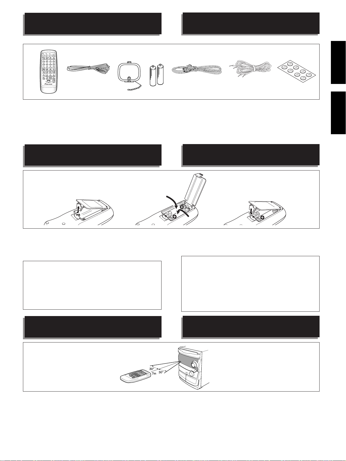
1 Remote control unit x 1
2 FM antenna x 1
3 AM loop antenna x 1
4 AA/R6P dry cell batteries x 2
5 Power cord x 1
6 Speaker cords x 2
7 Non-skid Pads x 1
LOADING BATTERIES INTO THE
REMOTE CONTROL UNIT
1
2
1 Télécommande x 1
2 Antenne FM x 1
3 Antenne cadre AM x 1
4 Piles sèches AA/R6P x 2
5 Cordon d’alimentation x 1
6 Cordons d’enceinte x 2
7 Feutres antidérapants x 1
INTRODUIRE LES PILES DANS LA
TELECOMMANDE
3
6
Included with speaker system
Fournis avec les enceintes
7
EnglishFrançais
1 Open the battery compartment cover on the back of the remote
control unit.
2 Insert two AA/R6P dry cell batteries into the battery compartment
in accordance with the indications (ª, ·) inside the compartment.
3 Close the cover of the battery case.
Incorrect use of batteries may cause leakage or rupture.
Always be sure to follow these guidelines:
A. Always insert batteries into the battery compartment correctly
matching the positive ª and negative · polarities, as shown
by the display inside the compartment.
B. Never mix new and used batteries.
C. Batteries of the same size may have different voltages,
depending on brand. Do not mix different brands of batteries.
REMOTE CONTROL OPERATIONS
The remote control unit can be used within a range of approx.
7 meters from the remote sensor, and within angles of up to
approx. 30 degrees.
NOTE:
If the remote control sensor window is in a position where it receives
strong light such as sunlight or fluorescent light, control may not be
possible.
1 Ouvrez le coffret à piles à l'arrière de la télécommande.
2 Introduisez des piles de taille AA/R6P dans le coffret en prenant les
marques (ª, ·) à l'intérieur du coffret comme repère.
3 Remettez le couvercle du coffret à piles en place.
Une utilisation erronée des piles peut provoquer des fuites, voire
une explosion.
Respectez les instructions suivantes:
A. Introduisez toujours les piles dans le bon sens en faisant
correspondre les repères de polarité ª et · des piles avec
ceux qui figurent à l'intérieur du coffret.
B. Ne mélangez jamais piles neuves et piles usagées.
C. Des piles de la même forme peuvent avoir une tension
différente selon la marque. Ne mélangez pas des différentes
marques de pile.
OPERATIONS DE TELECOMMANDE
L’unité de télécommande peut être utilisée dans un rayon
d’action d’environ 7 m à partir du capteur de télécommande
avec des angles allant jusqu’à environ 30°.
REMARQUE:
Si le capteur reçoit une lumière forte, comme des rayons de soleil ou
une lumière fluorescente, le fonctionnement de la télécommande
peut être entravé.
5
En/Fr
CONNECTIONS
RACCORDEMENTS
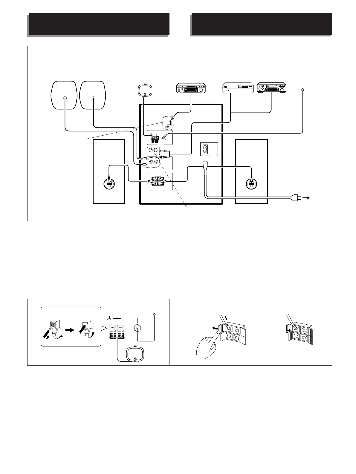
The illustration shows XR-A670.
L'illustration montre la XR-A670.
Rear speaker system (sold separately)
Enceintes arrières (vendues séparément)
XR-A370 does not have this
terminal.
Le modèle XR-A370 ne
possède pas cette prise.
Front speaker (R)
Enceinte avant droite
AM loop antenna
Antenne cadre AM
AM
LOOP
ANTENNA
L
R
AUX IN
L
R
REAR
SPEAKERS
ª
·
R
FRONT
SPEAKERS
Component (DAT, MD,
etc.) that has an optical
digital input jack.
Composant (DAT, MD, etc.)
avec prise jack pour entrée
optique numérique.
FM
UNBAL
75Ω
ANTENNA
L
L
R
R
L
INLET
AC
VCR
Magnétoscope
XR-A370 do not have these terminals.
Les modèles XR-A370 ne possèdent pas ces prises.
MD
MD (Minidisc)
Front speaker (L)
Enceinte avant gauche
To the AC wall outlet
Vers la prise de courant
FM antenna
Antenne FM
7 Before making or changing the connections, switch off
the power button and disconnect the power cord from
the AC outlet.
÷ Be sure to connect an antenna. If you don't, broadcast reception
will not be possible.
÷ Also refer to “ANTENNA CONNECTIONS” on page 8.
1.Connect AM loop antenna and FM antenna
to the unit's antenna terminals.
1 Twist the wire strands.
2 Push away the tab and insert the cord into the terminal.
3 Pull back the tab. Be sure to tighten the cords firmly.
7 Mettez l'appareil hors tension et retirez le cordon
d'alimentation de la prise de courant avant d'effectuer
ou de modifier les raccordements.
÷ N’oubliez pas de raccorder l’antenne, sinon la réception de
programmes sera impossible.
÷ Reportez-vous également à la page 8, “CONNEXIONS
D’ANTENNE”.
1.Raccordez l'antenne cadre AM et l'antenne
FM aux bornes d'antenne de l'appareil.
1 Torsadez les fils.
2 Repoussez le taquet et introduisez le cordon dans la borne.
3 Remettez le taquet et veillez à bien serrer les cordons.
13
32
AM
LOOP
ANTENNA
FM
UNBAL
75Ω
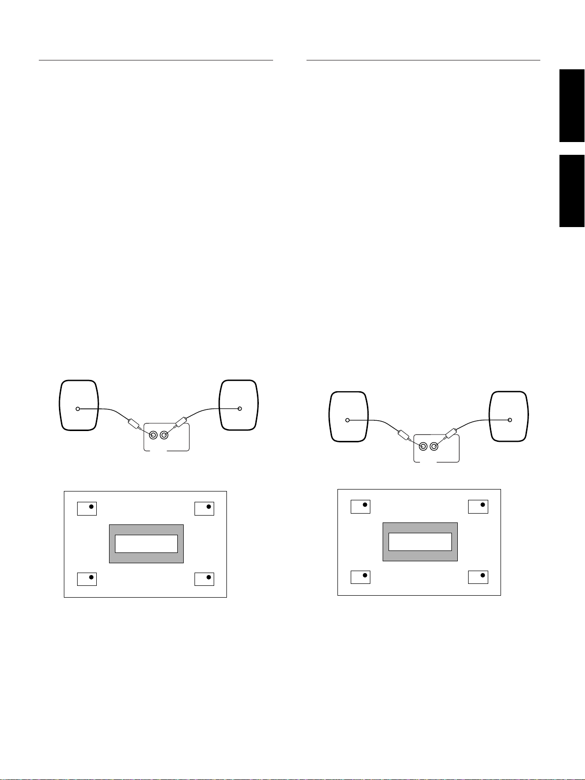
2.Affix one non-skid pad to each of the bottom
corners of the speakers.
3.Connect the speaker cords to the FRONT
SPEAKERS terminals.
Connect the gray cords to the “+” (red) terminals and the white
cords to the “–” (black) terminals.
1 Open the tab and insert the cord into the terminal.
2 Close the tab. Be sure to tighten the cords firmly.
12
2.Posez un feutre antidérapant sous chaque
coin de l’enceinte.
3.Reliez les cordons de liaison aux enceintes
aux bornes FRONT SPEAKERS.
Connecter les fils grises à la borne “+” (rouge) et les blanches à
la borne “–” (noir).
1 Ouvrez le taquet et introduisez le cordon dans la borne.
2 Refermez le taquet et veillez à bien serrer les cordons.
6
En/Fr
CONNECTIONS
RACCORDEMENTS
4.Connect the speaker connector.
Connect the gray cords to the “+” (red) terminals and the white
cords to the “–” (black) terminals.
NOTES:
÷
Do not allow the conductors of the cords to project out of the
terminals or to come into contact with other conductors.
A breakdown or failure may occur when conductors touch.
÷
Combine S-A3700 together with XR-A370 only.
÷
These speaker systems are not magnetically shielded, and may
cause color noise or distortion when placed very near a television
set. If this occurs, place the speakers farther away from the
television set.
(Precaution for S-A670)
÷
Do not place any items on top of speaker system.
Speaker impedance
Connect speaker systems with a nominal impedance ranging from
6 Ω to 16 Ω.
Precaution for S-A3700/S-A5700 and S-A6700 :
Do not connect these speaker systems to any amplifier
other than the one supplied with these systems. Connection to any other amplifier may result in a malfunc-
tion or a fire.
Rear speaker system connection (XR-A670 only)
÷ Make sure you connect the plugs properly.
÷ Rear speakers equipped with a pin plug and with nominal
impedance of 16 Ω or more can be connected.
4.Branchez le connecteur de chaque enceinte.
Connecter les fils grises à la borne “+” (rouge) et les blanches à
la borne “–” (noir).
REMARQUES:
÷
Faites en sorte que les conducteurs des fils ne sortent pas des
bornes et évitez tout contact avec d'autres conducteurs. Si les
conducteurs se touchent, vous risquez des pannes ou des
dysfonctionnements.
÷
Ne combinez le S-A3700 qu’avec le XR-A370.
÷
Ces enceintes acoustiques ne sont pas magnétiquement blindées
et elles peuvent donc causer des parasites ou une distorsion des
couleurs si elles sont placées près d’un téléviseur. Dans ce cas,
séparez les haut-parleurs et le téléviseur.
(Précaution pour le S-A670)
÷
Ne placez rien sur le système d'enceintes.
Impédance des enceintes
Raccordez des systèmes d'enceinte avec une impédance nominale
de 6 Ω à 16 Ω.
Précautions pour le S-A3700/S-A5700 et S-A6700 :
Ne reliez pas ces enceintes à un amplificateur autre que
celui fourni avec elles. Dans le cas contraire, vous pourriez
constater une anomalie de fonctionnement ou même
provoquer un incendie.
Raccordement du système d'enceintes arrière
(seulement XR-A670)
÷ Raccordez correctement les fiches.
÷ Des enceintes arrière équipées d'une prise à broches et à
impédance nominale de 16 Ω ou plus peuvent être connectées.
EnglishFrançais
L
R
REAR
SPEAKERS
Rear speaker installation example
Front speaker (L)
Listening area
Rear speaker (L) Rearspeaker (R)
When mounting rear speaker system on a wall
÷ Use the hole located on the rear panel of the speaker to mount it
on a wall.
Make sure the speakers are securely fixed to the wall.
÷ Check if the wall is strong enough to support the speakers.
PIONEER disclaims any & all responsibility for damage due to
falling speakers and/or other accidents, which are caused by
insufficient wall strength or any improper installation.
÷ No screws or other fittings are supplied to mount the speakers on
the wall.
Front speaker (R)
L
R
REAR
SPEAKERS
Exemple d'installation des enceintes arrière
Enceinte frontale (gauche) Enceinte frontale (droite)
Zone d’écoute
Listening area
Enceinte arrière (gauche) Enceinte arrière (droite)
Si vous accrochez les enceintes arrière au mur
÷ Servez-vous du trou dans le panneau arrière pour accrocher
l'enceinte au mur.
Vérifiez que les enceintes sont fermement fixées au mur.
÷ Vérifiez que le mur est suffisamment solide pour supporter les
enceintes. PIONEER décline toute responsabilité quant aux
dommages encourus suite à la chute des enceintes et/ou d’autres
incidents causés par une solidité insuffisante du mur ou une
installation inadéquate.
÷ Les vis et chevilles de montage ne sont pas fournis.
En/Fr
7
CONNECTIONS
OPTICAL
DIGITAL
IN
OPTICAL
DIGITAL
OUT
RACCORDEMENTS
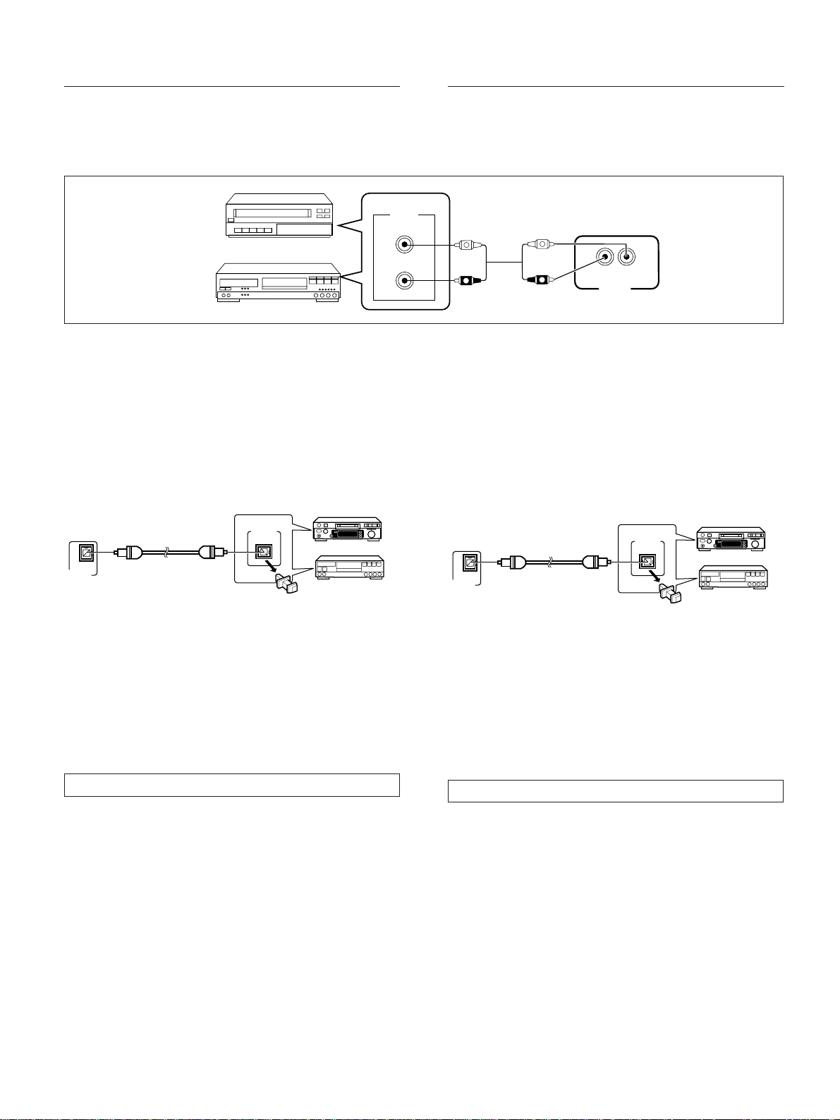
5.When using a video cassette recorder or MD
player, connect a separately sold stereo
audio cord to the AUX input jacks.
OUT
L
R
6.Lastly, plug the power cord into the AC
wall outlet.
NOTE:
Insert the plugs securely into the jacks. Improper connection can lead
to sound distortion or malfunction.
Optical digital jack connection
(The XR-A370 does not feature an optical digital jack so this
connection cannot be made.)
OPTICAL
DIGITAL
OPTICAL
DIGITAL
OUT
IN
MD
DAT
5.Si vous utilisez un magnétoscope ou un
lecteur de Minidisc, raccordez un cordon
audio stéréo vendu séparément aux entrées
AUX.
L
R
L
R
R
AUX IN
L
6.Pour terminer le raccordement, branchez le
cordon d’alimentation à la prise de courant.
REMARQUE :
Introduisez bien les fiches dans les prises jack. Un raccordement
inadéquat peut provoquer une distorsion du son ou des
dysfonctionnements.
Raccordement sur prise jack pour entrée optique numérique
(Le modèle XR-A370 ne possède pas de prise optique pour
signaux numériques, par conséquence ce raccordement ne
peut pas être effectué.)
MD
DAT
Connecting to a component (DAT, MD etc.) that has an optical digital
input jack.
÷ Connect the optical output jack of the unit to the optical input jack
of the connecting component with an optical cable.
÷ A separately sold optical cable is used for optical digital jack
connection. However, only components having the same type of
optical jack as this unit can be connected with this type of cable.
An adapter for digital hookup with a coaxial digital terminal is also
available separatly.
ANTENNA CONNECTIONS
Radio reception is not possible unless the antenna is properly
connected.
Reception varies from one area to another. Signal broadcast
tends to be especially poor in metropolitan areas where there
are many tall buildings and in mountainous areas. Proper
antenna installation is vital to good reception.
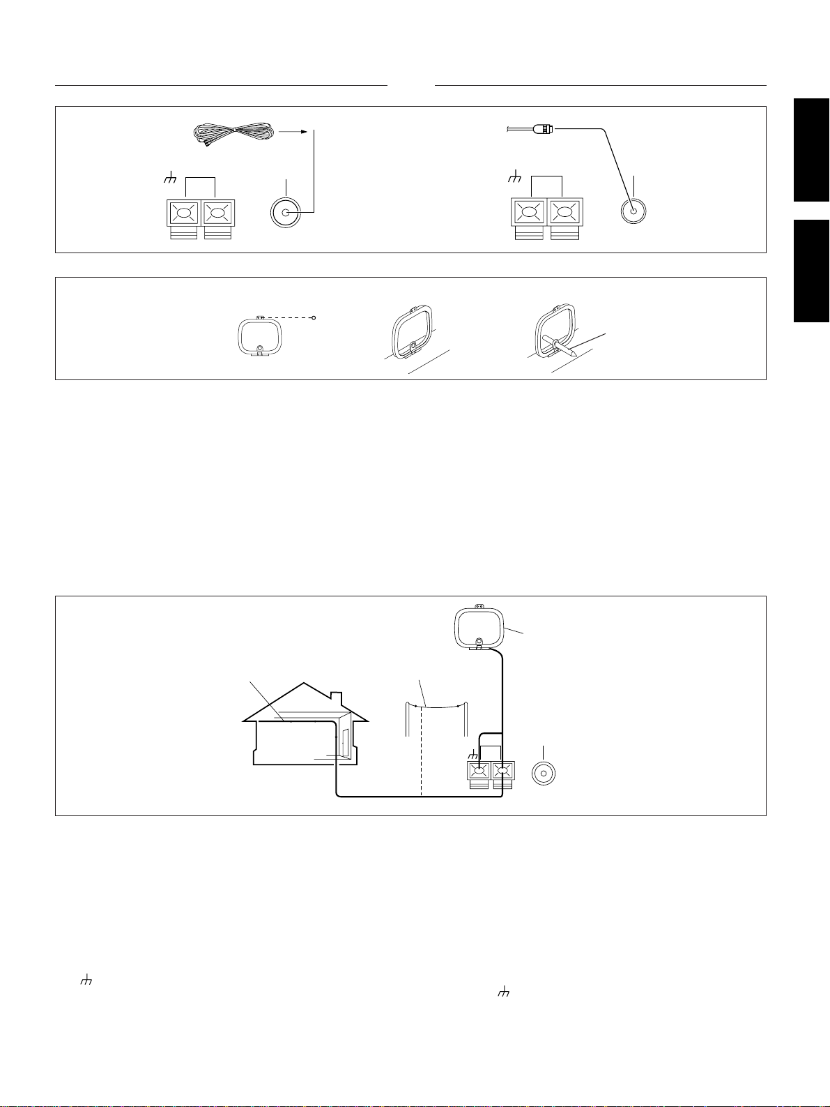
FM ANTENNA
A FM antenna
Fully extend the antenna and affix it to a wall, etc.
B External FM antenna installation
Use an external antenna when the signals from the stations are weak
and cannot be picked up with the supplied FM antenna. If the sound
heard is accompanied by too much noise, connect a 75 Ω coaxial
cable.
Raccordement à un composant (DAT, MD, etc.) sans entrée optique
numérique
÷ Raccordez la sortie optique de l’appareil à l’entrée optique du
composant à raccorder avec un câble en fibre optique.
÷ Un câble en fibre optique vendu séparément est utilisé pour le
raccordement à une prise jack optique numérique. Seuls les
composants possédant le même type de jack optique que cet
appareil peuvent être raccordés avec ce type de câble. Un
adaptateur de raccordement numérique avec borne numérique
coaxiale est également disponible séparément.
CONNEXIONS D’ANTENNE
La réception radio n’est pas possible si l’antenne n’est pas
correctement raccordée.
La réception varie d’une région à l’autre. La transmission du
signal a tendance à être particulièrement mauvaise dans les
zones métropolitaines comptant beaucoup d’immeubles élevés
et dans les zones montagneuses.
ANTENNE FM
A Antenne FM
Déployez entièrement l’antenne et fixez-la à un mur etc.
B Installation de l’antenne externe FM
Utilisez une antenne extérieure quand les signaux en provenance des
stations sont faibles et ne peuvent pas être captés avec l’antenne FM
fournie. Utilisez un câble coaxial 75 Ω si le son entendu s’accompagne
de beaucoup de bruit.
8
En/Fr
CONNECTIONS RACCORDEMENTS
AB
AM
LOOP
ANTENNA
FM
UNBAL
75Ω
AM ANTENNA
abc
The antenna should be placed at a distance from the unit, and
should not be allowed to touch metallic objects. Avoid placing
it near CD players, personal computers, television sets and
other devices generating radio frequencies.
÷ Place the antenna on a level surface and rotate it to find the
orientation that yields the best reception.
Setting up the AM antenna
There are three ways of setting up the AM antenna:
(See illustration a, b and c)
a: Fasten with a pin to the wall.
b: Stand the antenna up by itself.
c: Support with a ball pen or the like (not supplied).
External AM antenna
AM
LOOP
ANTENNA
FM
UNBAL
75Ω
ANTENNE AM
not supplied
non fourni
L’antenne doit être placée à bonne distance de l’appareil et ne
doit être au contact d’aucun objet métallique. Evitez de la placer
près de lecteurs de CD, d’ordinateurs familiaux, d’appareils de
télévision et autres appareils produisant des fréquences radio.
÷ Posez l’antenne sur une surface horizontale et tournez-la
jusqu’à ce que la réception soit aussi bonne que possible.
Installation de l'antenne AM
Il existe trois façons d'installer l'antenne AM:
(Voir les illustrations a, b et c)
a: Fixez l’antenne sur un mur au moyen d’une punaise.
b: Dressez l’antenne.
c: Maintenez l’antenne à l’aide d’un crayon ou d’un objet similaire.
(non fourni)
Antenne externe AM
EnglishFrançais
Indoor AM antenna
Antenne intérieure AM
Outdoor AM antenna
Antenne extérieure AM
Indoor AM antenna:
Use a vinyl-coated wire 5-6 meters long. Secure one end to the
AM terminal and the other end to a wall or other high location.
Outdoor AM antenna:
If reception is still poor even when a lead antenna has been fully
extended indoors, stretch out a vinyl-coated wire and secure it
outdoors.
NOTE:
Do not detach the AM loop antenna when using the external AM
antenna.
The (signal earth) helps reduce noise when an antenna is
connected. It is not a safety earth.
AM loop antenna
Antenne cadre AM
AM
LOOP
ANTENNA
FM
UNBAL
75Ω
Antenne intérieure AM
Utilisez un fil gainé de vinyle (5 à 6 mètres de long). Fixer l’une
des extrémités sur la borne AM et l’autre extrémité sur le mur
ou un autre endroit en hauteur.
Antenne extérieure AM
Si malgré une antenne intérieure, la qualité de la réception n’est
pas suffisamment bonne, un fil isolé avec du vinyle doit être
installé à l’extérieur.
REMARQUE:
Conservez l’antenne cadre AM branchée lors de l’utilisation
d’une antenne AM intérieure ou extérieure.
Le symbole (masse signal) contribue à réduire le bruit quand
on a raccordé une antenne. Il ne s’agit pas d’une mise à la masse
pour la sécurité.
En/Fr
9

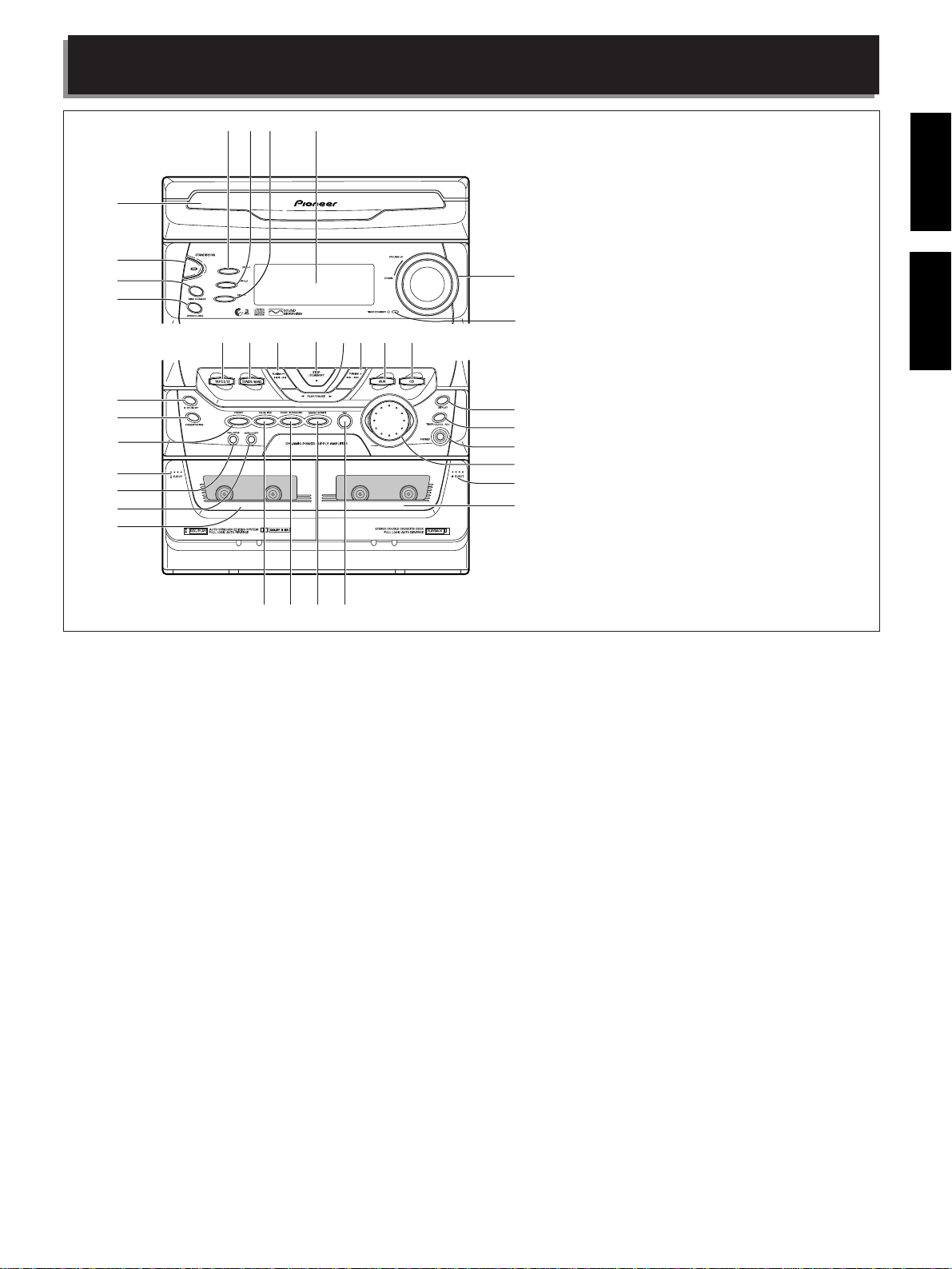
NAMES AND FUNCTIONS OF PARTS
123 4
5
6
7
8
^
%
$#
@!~=-
P
R
H
O
I
N
M
G
D
N
J
U
O
O
G
S
&
*
(
)
_
+
¢
£
™
¡
1 DISC-1 select button & indicator
2 DISC-2 select button & indicator
3 DISC-3 select button & indicator
4 Display
5 CD disc tray
6 STANDBY/ON switch
<TURNING ON THE POWER>
÷ When the power plug is connected to an AC wall outlet, the unit
enters the demonstration mode. Press the Power button to cancel
the demonstration mode.
Press the STANDBY/ON switch .
To switch the power OFF (STANDBY):
Press the STANDBY/ON switch.
“GOOD BYE” is displayed.
Standby indicator lights.
7 DISC CHANGE button
8 OPEN/CLOSE button (Also switches power on if in standby.)
9 Volume control (VOLUME)
0 TIMER STANDBY indicator
- CD function button (Also switches power on if in standby.)
= AUX function button
(Also switches power on if in standby. If the auxiliary component
is already playing, then you'll hear it.)
~ TUNING + ¡ • ¢ button
! PLAY/PAUSE button
(Also switches power on if in standby.)
@ STOP/ST.MEMORY button
# TUNING – 4 • 1 button
*
*
(15, 21, 22, 26, 27)
(21, 22, 26, 27)
*
(16, 21, 22, 26, 27)
*
(15, 21, 22, 26, 27)
$ TUNER/BAND function button
(Also switches power on if in standby.)
% TAPE I/II function button
(Also switches power on if in standby.)
^ XR-A370 : REPEAT button
XR-A670 : Dolby**
2 NR ON/OFF button
The illustration shows XR-A670.
9
0
º
ª
•
¶
§
∞
&
FREQ/STATION button
7 Auto Play Function
If you press the CD function button when a CD is
loaded, the CD automatically starts playing. If you
press the TAPEI/II function button when a tape is
loaded in the cassette deck, the tape automatically
starts playing.
NOTE:
You cannot change the function during recording
and tape copying.
* PRESET button
( TAPE I Eject button (0)
) REC/STOP button
_ ASES/COPY button
+ TAPE I cassette door
¡ EQUALIZER button
™ ZOOM SURROUND button
£ P.BASS (DEMO) button
¢ SET button
∞ TAPE II cassette door
§ TAPE II Eject button (0)
¶ SOUND MORPHING JOG (S. M. JOG)
• PHONES jack (Headphones)
ª TIMER/CLOCK ADJ button
º DISPLAY button
*
÷ The functions of some buttons changes depending on the
input. To learn about rhe different functions see the page
numbers in parenthesis.
**
÷
Dolby noise reduction manufactured under license from Dolby
Laboratories Licensing Corporation.
÷
“DOLBY” and the double-D symbol are trademarks of Dolby
Laboratories Licensing Corporation.
10
En/Fr
NOMS ET FONCTIONS DES PIECES
123 4
5
6
7
8
^
%
$#
@!~=-
P
R
H
O
I
N
M
G
D
N
J
U
O
O
G
S
&
*
(
)
_
+
¢
£
™
¡
1 Touche et témoin de sélection DISC-1
2 Touche et témoin de sélection DISC-2
3 Touche et témoin de sélection DISC-3
4 Ecran d'affichage
5 Plateau de disque CD
6 Touche STANDBY/ON
<METTRE L'APPAREIL SOUS TENSION>
÷ Lorsque la fiche est introduite dans la prise de courant, l'appareil
passe en mode démonstration. Appuyez sur la touche POWER
pour mettre fin au mode démonstration.
Appuyez sur l'interrupteur STANDBY/ON .
Pour mettre l'appareil hors tension (STANDBY):
Appuyez une deuxième fois sur l'interrupteur STANDBY/ON.
Les mots “GOOD BYE” apparaissent.
Le témoin de veille s’éclaire.
7 Touche DISC CHANGE
8 Touche ouvrir/fermer (OPEN/CLOSE)
(Met aussi l'appareil sous tension s'il est en attente.)
9 Réglage volume (VOLUME)
0 Témoin TIMER STANDBY
- Touche de sélection CD
(Met aussi l'appareil sous tension s'il est en attente.)
= Touche de sélection AUX
(Met aussi l'appareil sous tension s'il est en attente. Si la lecture
a déjà commencé sur les composants auxiliaires, ils seront
audibles.)
~ Touche TUNING + ¡ • ¢
! Touche PLAY/PAUSE
(Met aussi l'appareil sous tension s'il est en attente.)
@ Touche STOP/ST.MEMORY
# Touche TUNING – 4 • 1
*
*
(15, 21, 22, 26, 27)
(21, 22, 26, 27)
*
(16, 21, 22, 26, 27)
*
(15, 21, 22, 26, 27)
$ Touche de sélection TUNER/BAND
(Met aussi l'appareil sous tension s'il est en attente.)
% Touche de sélection TAPE I/II
(Met aussi l'appareil sous tension s'il est en attente.)
L'illustration montre la XR-A670.
9
0
º
ª
•
7 Fonction de lecture automatique
¶
Si vous appuyez sur la touche CD de sélection du
§
lecteur de CD alors qu’un CD est en place dans l’appareil,
sa lecture commence aussitôt. Pareillement, Si vous
∞
appuyez sur la touche TAPEI/II de sélection de la platine
à cassette alors qu’une cassette est en place dans
l’appareil, sa lecture commence aussitôt.
REMARQUE :
Vous ne pouvez pas changer de fonction pendant
l'enregistrement et la copie d'une cassette.
^ XR-A370 : Touche REPEAT
XR-A670 :
Touche Dolby** 2 NR marche/arrêt (ON/OFF)
& Touche FREQ/STATION
* Touche PRESET
( Touche d'éjection TAPE I (0)
) Touche enregistrement/arrêt (REC/STOP)
_ Touche ASES/COPY
+ Volet cassette TAPE I
¡ Touche EQUALIZER
™ Touche ZOOM SURROUND
£ Touche P.BASS (DEMO)
¢ Touche SET
∞ Volet cassette TAPE II
§ Touche d'éjection TAPE II (0)
¶ SOUND MORPHING JOG (S. M. JOG)
• Prises jack casques (PHONES)
ª Touche TIMER/CLOCK ADJ
º Touche DISPLAY
*
÷ La fonction de certaines touches varie selon l'entrée. Pour les
informations sur les différentes fonctions, consultez le numéro
de page indiqué entre parenthèses ().
**
÷
Réduction de bruit Dolby fabriquée sous licence de Dolby
Laboratories Licensing Corporation.
÷
DOLBY et le symbole double-D sont des marques de Dolby
Laboratories Licensing Corporation.
11
En/Fr
EnglishFrançais
Fr
NAMES AND FUNCTIONS OF PARTS
NOMS ET FONCTIONS DES PIECES
!
@
#
~
=
-
0
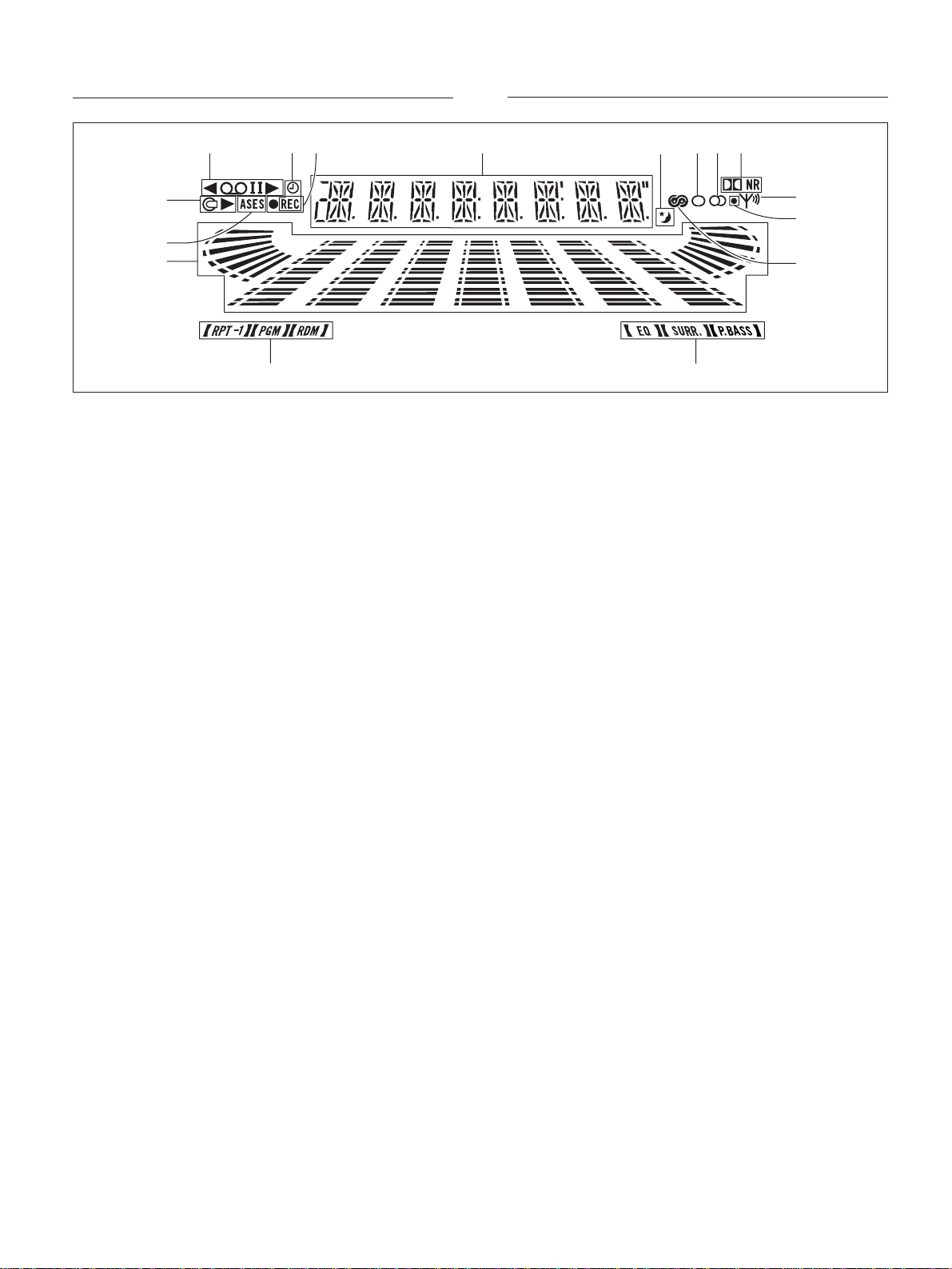
Display section
1 Displays a wide range of operation status indications.
2 Lights during Sleep Timer operation.
3 Lights when the MONO mode is selected.
4 Lights during FM stereo reception.
5 Lights when Dolby NR is on. (XR-A670 only)
6 Indicates tuner reception status.
7 Lights when BEAT CUT 2 is selected. (XR-A670 only)
8 Lights when the RDS mode is selected.
9 Indicates SOUND MORPHING status.
0 Indicates CD function status.
- Indicates Audio level.
= Lights during ASES operation.
~ Indicates CD play status.
! Indicates TAPE play status.
@ Displays timer function indications.
# Lights during recording.
21
435
6
7
8
9
Section affichage
1 Affiche diverses indications relatives au
fonctionnement.
2 Ce témoin s’éclaire pendant le fonctionnement du
programmateur de mise hors service.
3 Ce témoin s'éclaire quand le mode MONO est
sélectionné.
4 Ce témoin s'éclaire pendant la réception FM stéréo.
5 Ce témoin s'éclaire quand Dolby NR est activé.
(XR-A670 seulement)
6 Indique les conditions de réception du syntoniseur.
7 Ce témoin s’éclaire lorsque vous choisissez BEAT
CUT 2. (XR-A670 seulement)
8 Ce témoin s’éclaire lorsque le mode RDS est choisi.
9 Indique les conditions de la correction SOUND
MORPHING.
0 Indique les conditions du lecteur de CD.
- Ceci indique le niveau sonore.
= Ce témoin s’éclaire pendant l’usage de la fonction
ASES.
~ Indique l'état de lecture du CD.
! Indique l'état de lecture de la cassette (TAPE).
@ Affiche les informations relatives au
programmateur.
# Ce témoin s’éclaire pendant un enregistrement.
12
En/Fr
NAMES AND FUNCTIONS OF PARTS NOMS ET FONCTIONS DES PIECES
REMOTE CONTROL UNIT
TELECOMMANDE
1
2
3
4
1
2
3
-
=
~
!
EnglishFrançais
5
6
7
8
9
0
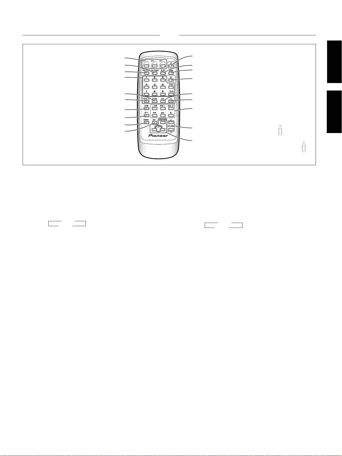
1 DISC select buttons (1-3)
2 DISC CHANGE button
3 OPEN/CLOSE button
4 Digit (1-9, 10/0, >10) buttons
5 BAND button
Use to switch between FM and AM bands.
3 FM
AM 2
6 TAPE I / II function button
7 RDM button
8 RPT button
9 MONO button
0 DISP button
- STANDBY / ON button
= SLEEP button
~ PGM button
! CLEAR button
@ AUX function button
# CD function button
$ CD/TAPE/STATION (up, down) operation buttons
¶ CD operation buttons
(Play/Pause 6 , Track search 4 ¢ , Stop 7, Fast 1 ¡ )
¶ TAPE operation buttons
(Play 2 3 , Music Search 4 ¢ , Stop 7, Fast 1 ¡ )
(The XR-A370 do feature the Music Search 4 ¢ function.)
¶ TUNER buttons
+ ....... Move to the next station.
– ........ Move to the previous station.
1 .... Frequency down.
¡ .... Frequency up.
% VOLUME 5 (up), ∞ (down) buttons
^ SOUND MORPHING MODE button & SOUND
MORPHING JOG control buttons
@
#
$
%
Operations indicated by the [ ] mark are
performed with the remote control unit.
^
Les opérations indiquées par le symbole [ ]
s'effectuent avec la télécommande.
1 Touches de sélection DISC (1-3)
2 Touche DISC CHANGE
3 Touche ouvrir/fermer (OPEN/CLOSE)
4 Touches numériques (1-9, 10/0, >10)
5 Touche BAND
Pour faire commuter les bandes FM et AM.
3 FM
AM 2
6 Touche de fonction TAPE I / II
7 Touche RDM
8 Touche répétition (RPT)
9 Touche MONO
0 Touche affichage (DISP)
- Touche mise sous tension (STANDBY/ON)
= Touche minuterie arrêt automatique (SLEEP)
~ Touche programme (PGM)
! Touche effacer (CLEAR)
@ Touche de fonction AUX
# Touche de fonction CD
$ Touches d'opération CD/TAPE/STATION (avance, recul)
¶ Touches d'opération CD
(Lecture/Pause 6 , Recherche piste 4 ¢ , Arrêt 7,
Balayage rapide 1 ¡ )
¶ Touches d'opération TAPE (cassette)
(Lecture 2 3 , Recherche chanson 4 ¢ , Arrêt 7,
Balayage rapide 1 ¡ )
(Le modèle XR-A370 ne possède pas la touche de recherche
de plage musicale 4 ¢ .)
¶ Touches TUNER
+....... Passe à la station suivante.
– ....... Passe à la station précédente.
1 .... Fréquence plus haute.
¡ .... Fréquence plus basse.
% Touches VOLUME 5 (augmenter), ∞ (diminuer)
^ Touche SOUND MORPHING MODE et touches de
commande SOUND MORPHING JOG
13
En/Fr
SETTING THE CLOCK
P
R
H
O
I
N
M
G
D
N
J
U
O
O
G
S
3,4, 5
REGLER L'HORLOGE
1
2,4, 5
1
2
P
R
H
O
I
N
M
G
D
N
J
U
O
O
G
S
3
45
P
R
H
O
I
N
M
D
N
U
O
S
\
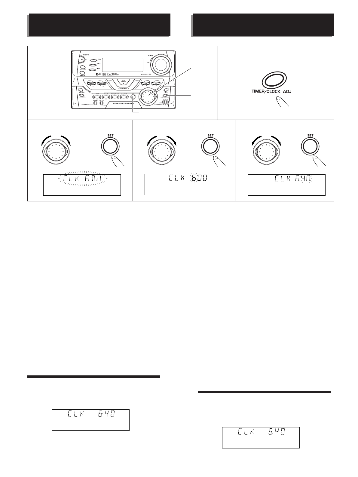
÷ When the power plug is first connected, the unit automatically
enters the demo (demonstration) display mode. Press the
STANDBY / ON switch to cancel the demo mode, then set the
clock display to the current time.
÷ Set the clock when it is incorrectly set, or when power to the
unit is cut.
÷ The time is displayed as a 24 hour clock.
÷ The clock cannot be set with the remote control unit.
Example: Setting the clock to 6:40
1. Press the TIMER/CLOCK ADJ button.
2. Turn the S. M. JOG until “CLOCK ADJ” is
indicated on the display.
3. Press the SET button.
4. Turn the S. M. JOG to set the "Hour” then
press SET button. (“6” is selected in the
example)
5. Turn the S. M. JOG to set the “Minute” then
press SET button. (“40” is selected in the
example)
÷ After connecting to an AC outlet, be sure to set the time. Timer
playback is not possible unless the time has been set.
÷ The time display will flash when the power is restored following
a power failure, or if the power cord has been disconnected. In
this case, be sure to set the present time again.
7 To display the clock
Press the DISPLAY button.
Clock indications disappear after about 5 seconds.
P
R
H
O
I
N
G
J
O
G
\
M
G
D
N
J
U
O
O
G
S
\
÷ Lorsque cordon d'alimentation est branché pour la première fois,
l'appareil passe automatiquement en mode “DEMO”
(démonstration). Appuyez sur la Touche STANDBY/ON pour mettre
fin au mode “DEMO” et réglez ensuite l'horloge sur l'heure en
cours.
÷ Réglez l'horloge si elle est mal réglée, ou si l'alimentation de
l'appareil a été coupée.
÷ L'heure est affichée au format 24 heures.
÷ Vous ne pouvez pas régler l'heure à l'aide de la télécommande.
Exemple: Régler l'horloge sur 6h40
1. Appuyez sur la touche TIMER/CLOCK ADJ.
2. Tournez le bouton de réglage (S.M. JOG)
jusqu’à ce que “CLK ADJ” s’affiche.
3. Appuyez sur la touche SET.
4. Tournez le bouton de réglage (S.M. JOG) pour
régler l'heure, puis appuyez sur la touche SET.
(“6” a été choisi pour l’exemple présent.)
5. Tournez le bouton de réglage (S.M. JOG) pour
régler les minutes, puis appuyez sur la touche
SET. (“40” a été choisi pour l’exemple présent.)
÷ Veillez à régler l'horloge sur l'heure en cours après raccordement
à une prise de courant. La lecture à une heure donnée ne sera pas
possible sans ce réglage.
÷ L'affichage de l'horloge clignote après une coupure de courant, ou
si l'appareil a été débranché. Dans ce cas, il faut également
remettre l'horloge à l'heure.
7 Pour afficher l’heure
Appuyez sur la touche DISPLAY.
L’heure s’efface au bout de 5 secondes environ.
14
En/Fr
TUNING INTO STATIONS
RECHERCHER DES STATIONS
÷ Do not place the AM antenna on a metallic case including the
receiver cabinet or near a CD player, LD player, DAT recorder,
personal computer or TV set. Any of these installations will cause
noise during reception.
÷ Broadcast reception is not possible unless an antenna is connected,
so be sure to connect one.
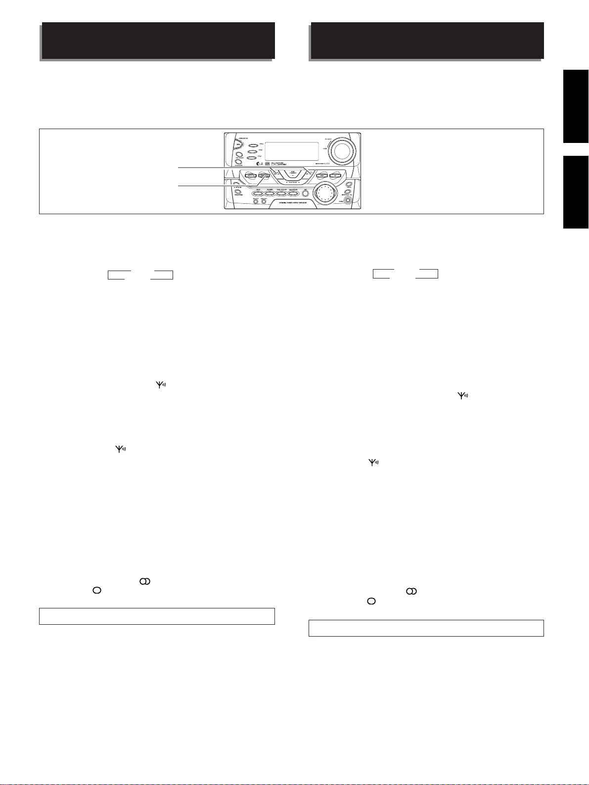
2
1
1. Select FM or AM with the TUNER/BAND button
or BAND button on the remote control unit.
Select the AM or FM broadcasting band.
Each press of the button alternates between AM and FM.
3 FM
AM 2
If you press this button when the unit is in standby mode, the
power will switch on and the function switches to TUNER.
2. Press the tuning/station call – 4 • 1 or + ¡
• ¢ button for lower or higher frequencies.
[Manual tuning]
Press the – 4 • 1 or + ¡ • ¢ button or 1 ¡ button on
the remote control unit and release quickly.
The tuning frequency will change by one step each time the button
is pressed. Press as many times as necessary to tune in to the desired
station. The TUNED indicator ( ) lights up when a station is
available.
[Auto tuning]
Press the – 4 • 1 or + ¡ • ¢ button or 1 ¡ button on
the remote control unit until the frequency starts to change, then
release it.
The tuner will automatically search for a station. When one is found,
the TUNED indicator ( ) lights. To search for another station, press
again.
÷ To interrupt auto tuning, press the – 4 • 1 or + ¡ • ¢
button again.
[High-speed manual tuning]
Press and hold the – 4 • 1 or + ¡ • ¢ button or 1 ¡
button on the remote control unit.
= The frequency continues to change until you let go of the button.
MONO button (Remote control unit only)
During FM reception: Switches between stereo and mono modes
when listening to a stereo broadcast. If there is a lot of noise in the
STEREO mode, switch to MONO and the noise will be reduced or
eliminated altogether.
(In the main unit’s display, “
possible, and “
” lights when MONO is selected.)
Beat cut function
(This function is not available on the XR-A370.)
If noise occurs during AM broad cast recording, perform the following
procedures to reduce the noise.
1. Turn off the power.
2. During standby, press the REC/STOP button
for more than 3 seconds.
The BEAT CUT 2 indicator (the small round indicator in the right
hand corner of the display) lights.
¶ To cancel the BEAT CUT 2 function, repeat steps 1 and 2.
” lights when STEREO receotion is
÷ Ne posez pas l'antenne AM sur une surface métallique, y compris le coffret
du récepteur, ni à proximité d'un lecteur de CD, d'un lecteur de LD, d'un
enregistreur de cassette numérique (DAT), d'un ordinateur ou d'un téléviseur.
Toutes ces installations causeront des parasites pendant la réception.
÷ Vous ne pouvez pas recevoir de programmes, si aucune antenne
n'est raccordée. Assurez-vous donc d'en raccorder au moins une.
P
R
H
O
I
N
M
G
D
N
J
U
O
O
G
S
1. Sélectionnez FM ou AM avec la touche TUNER/BAND
ou la touche BAND de la télécommande.
Sélectionnez la bande AM ou FM.
Chaque pression de la touche commute entre AM et FM.
3 FM
AM 2
Si vous appuyez sur cette touche alors que l'appareil est en mode de
veille, il se mettra sous tension et la fonction sera commutée à TUNER.
2. Appuyez sur la touche réglage sur station/appel de
station – 4 • 1 ou + ¡ • ¢ pour sélectionner
des fréquences plus hautes ou plus basses.
[Recherche de station manuelle]
Appuyez brièvement sur la touche – 4 • 1 ou + ¡ • ¢ ou la
touche 1 ¡ de la télécommande.
La fréquence de station change d'une unité à chaque appui sur la
touche. Appuyez autant de fois qu'il faut sur la touche pour atteindre
la station souhaitée. Le voyant TUNED (
) s'allume lorsque la
station captée est reçue de façon optimale.
[Recherche de station automatique]
Appuyez sur la touche – 4 • 1 ou + ¡ • ¢ ou la touche 1
¡ de la télécommande jusqu'à ce que la fréquence commence à
changer et lâchez.
Le tuner recherche automatiquement une station émettrice et le
voyant TUNED (
) s'allume quand il en trouve une. Appuyez de
nouveau pour rechercher une autre station.
÷ Pour interrompre la recherche automatique, appuyez de nouveau
sur la touche – 4 • 1 ou + ¡ • ¢.
[Recherche manuelle rapide]
Appuyez de façon continue sur la touche – 4 • 1 ou + ¡ • ¢
ou la touche 1 ¡ de la télécommande.
= La fréquence continue à changer jusqu'à la libération de la touche.
Touche MONO (seulement avec la télécommande)
Pendant la réception FM: Fait alterner les modes stéréo et mono
pendant l'écoute d'émissions de radio stéréo. S'il y a beaucoup de
parasites en mode stéréo, passez en MONO pour réduire le bruit ou
le faire disparaître.
(Sur l'afficheur de l'appareil, " " s'éclaire quand la réception STEREO
est possible, et " " quand MONO est sélectionné.)
Fonction suppression de battement (Beat Cut)
(Cette fonction n'est pas disponible sur le XR-A370.)
S'il y a du bruit pendant une émission AM, effectuez la procédure
suivante pour réduire le bruit.
1. Mettez l'appareil hors tension.
2. En position stand-by (veille), appuyez plus de
3 secondes sur la touche REC/STOP.
Le témoin BEAT CUT 2 (petit témoin circulaire dans le coin droit de
l'afficheur) s'éclaire.
¶ Pour mettre fin à la fonction BEAT CUT 2, répétez les étapes
1 et 2.
15
En/Fr
EnglishFrançais
 Loading...