

Pioneer XR-A660 Service Manual
XR-A660
STEREO CD CASSETTE DECK RECEIVER
XR-A660
XR-A330
THIS MANUAL IS APPLICABLE TO THE FOLLOWING MODEL(S) AND TYPE(S).
Type
KUCXJ AC120V
YPWXJ AC240V
XR-A660 XR-A330
Model
Power Requirement Remarks
ORDER NO.
RRV2064
CONTENTS
1. SAFETY INFORMATION ...................................... 2
2. EXPLODED VIEWS AND PARTS LIST................ 4
3. SCHEMATIC DIAGRAM ..................................... 18
4. PCB CONNECTION DIAGRAM.......................... 34
5. PCB PARTS LIST ............................................... 46
6. ADJUSTMENT .................................................... 53
PIONEER ELECTRONIC CORPORATION 4-1, Meguro 1-Chome, Meguro-ku, Tokyo 153-8654, Japan
PIONEER ELECTRONICS SERVICE, INC. P.O. Box 1760, Long Beach, CA 90801-1760, U.S.A.
PIONEER ELECTRONIC (EUROPE) N.V. Haven 1087, Keetberglaan 1, 9120 Melsele, Belgium
PIONEER ELECTRONICS ASIACENTRE PTE. LTD. 253 Alexandra Road, #04-01, Singapore 159936
PIONEER ELECTRONIC CORPORATION 1998
7. GENERAL INFORMATION ............................... 62
7.1 PARTS ......................................................... 62
7.1.1 IC ......................................................... 62
7.1.2 DISPLAY.............................................. 69
7.2 DISASSEMBLY ........................................... 73
7.3 BLOCK DIAGRAM....................................... 76
8. PANEL FACILITIES AND SPECIFICATIONS.... 78
T – ZZK DEC. 1998 Printed in Japan
XR-A660, XR-A330
1. SAFETY INFORMATION
This service manual is intended for qualified service technicians; it is not meant for the casual
do-it-yourselfer. Qualified technicians have the necessary test equipment and tools, and have been
trained to properly and safely repair complex products such as those covered by this manual.
Improperly performed repairs can adversely affect the safety and reliability of the product and may
void the warranty . If you are not qualified to perform the repair of this product properly and safely, you
should not risk trying to do so and refer the repair to a qualified service technician.
WARNING
This product contains lead in solder and certain electrical parts contain chemicals which are known to the state of California to
cause cancer, birth defects or other reproductive harm.
Health & Safety Code Section 25249.6 – Proposition 65
NOTICE
(FOR CANADIAN MODEL ONLY)
Fuse symbols (fast operating fuse) and/or (slow operating fuse) on PCB indicate that replacement
parts must be of identical designation.
REMARQUE
(POUR MODÈLE CANADIEN SEULEMENT)
Les symboles de fusible (fusible de type rapide) et/ou (fusible de type lent) sur CCI indiquent que
les pièces de remplacement doivent avoir la même désignation.
(FOR USA MODEL ONLY)
1. SAFETY PRECAUTIONS
The following check should be performed for the
continued protection of the customer and service
technician.
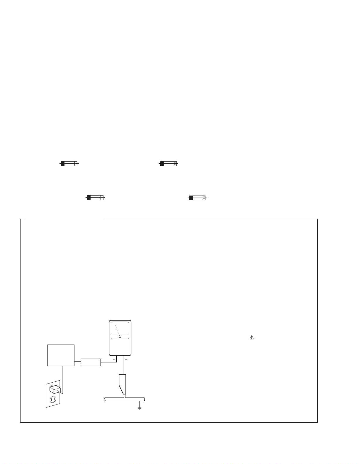
LEAKAGE CURRENT CHECK
Measure leakage current to a known earth ground
(water pipe, conduit, etc.) by connecting a leakage
current tester such as Simpson Model 229-2 or
equivalent between the earth ground and all exposed
metal parts of the appliance (input/output terminals,
screwheads, metal overlays, control shaft, etc.). Plug
the AC line cord of the appliance directly into a 120V
AC 60 Hz outlet and turn the AC power switch on. Any
current measured must not exceed 0.5 mA.
Reading should
not be above
0.5 mA
Earth
ground
Device
under
test
Also test with
plug reversed
(Using AC adapter
plug as required)
Test all
exposed metal
surfaces
AC Leakage Test
Leakage
current
tester
ANY MEASUREMENTS NOT WITHIN THE
LIMITS OUTLINED ABOVE ARE INDICATIVE
OF A POTENTIAL SHOCK HAZARD AND
MUST BE CORRECTED BEFORE RETURNING THE APPLIANCE TO THE CUSTOMER.
2. PRODUCT SAFETY NOTICE
Many electrical and mechanical parts in the appliance
have special safety related characteristics. These are
often not evident from visual inspection nor the
protection afforded by them necessarily can be obtained
by using replacement components rated for voltage,
wattage, etc. Replacement parts which have these
special safety characteristics are identified in this
Service Manual.
Electrical components having such features are
identified by marking with a
on the parts list in this Service Manual.
The use of a substitute replacement component which
does not have the same safety characteristics as the
PIONEER recommended replacement one, shown in the
parts list in this Service Manual, may create shock, fire,
or other hazards.
Product Safety is continuously under review and new
instructions are issued from time to time. For the latest
information, always consult the current PIONEER
Service Manual. A subscription to, or additional copies
of, PIONEER Service Manual may be obtained at a
nominal charge from PIONEER.
on the schematics and
2
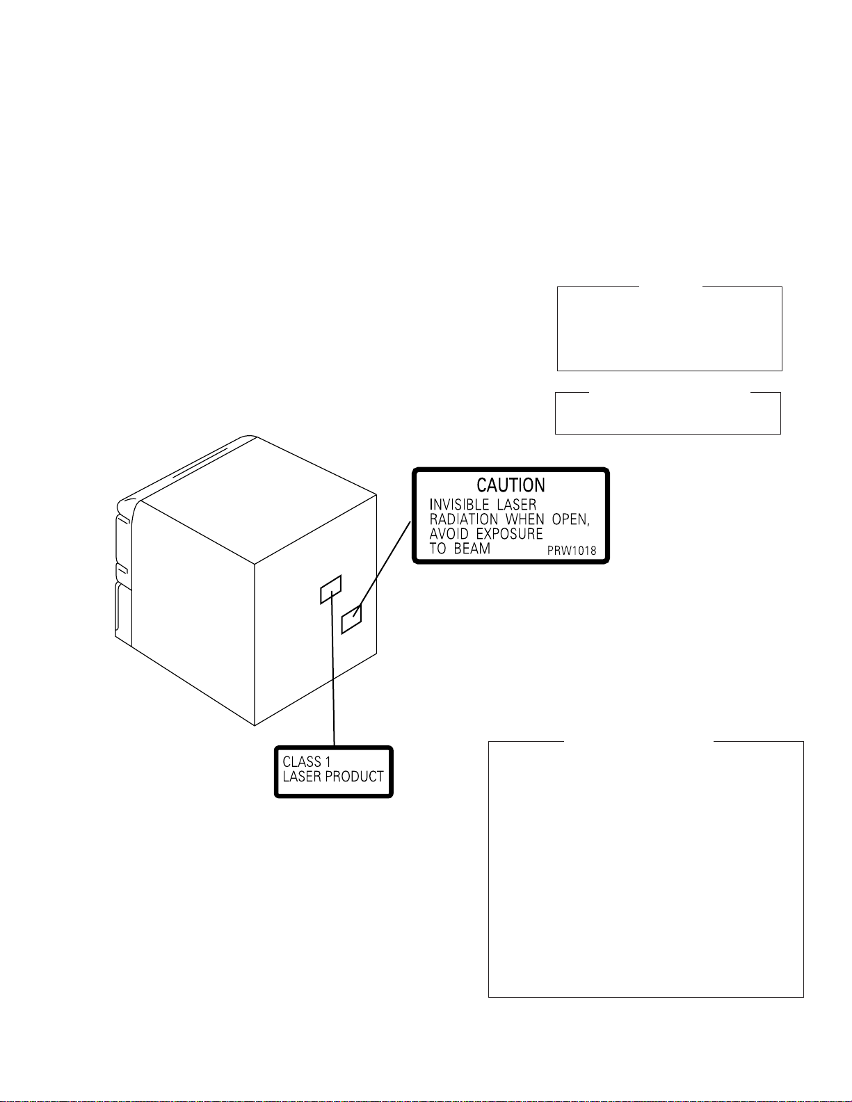
LABEL CHECK (for YPWXJ type)
XR-A660, XR-A330
THIS PIONEER APPARATUS CONTAINS
LASER OF CLASS 1.
SERVICING OPERATION OF THE APPARATUS
SHOULD BE DONE BY A SPECIALLY
INSTRUCTED PERSON.
LASER DIODE CHARACTERISTICS
MAXIMUM OUTPUT POWER: 1.3 mW
WAVELENGTH: 790 nm ± 25 nm
IMPORTANT
Printed on the Rear Panel
Additional Laser Caution
1.Laser Interlock Mechanism
The position of the switch (S8501) for detecting loading
state is detected by the system microprocessor, and
the design prevents laser diode oscillation when the
switch (S8501) is pressed physically.
Thus, the interlock will no longer function if the switch (S8501)
is released physically and deliberatery.
The interlock also does not function in the test mode ∗.
Laser diode oscillation will continue, if pin 62 of
LA9240ML (IC8101) on the CD ASSY mounted on the
$M Loading Mechanism assembly is connected to GND,
or else the terminals of Q8101 are shorted to each other
(fault condition).
2.When the cover is opened, close viewing of the
objective lens with the naked eye will cause exposure
to a Class 1 laser beam.
∗
: Refer to page 61.
3
XR-A660, XR-A330
2. EXPLODED VIEWS AND PARTS LIST
NOTES:
Parts marked by "NSP" and can not be supplied.
•
The mark found on some component parts indicates the importance of the safety factor of the part.
•
Therefore, when replacing, be sure to use parts of identical designation.
Screws adjacent to mark on the product are used for disassembly.
•
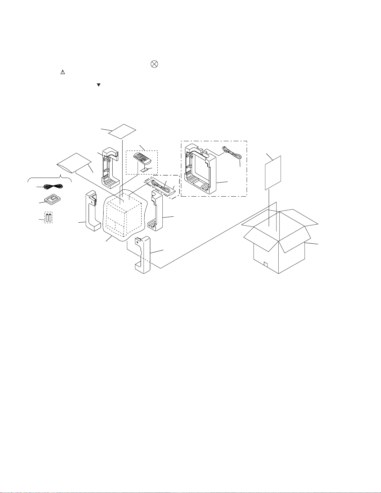
2.1 PACKING
KUCXJ Type Only
1
3
6
8(1/2)
9(1/2)
12
YPWXJ Type Only
4
VOL
K
A
R
A
O
K
E
S
DISC DISC DISC
F
S
C
L
E
E
P
P
.B
POWER
CLEAR
A
S
S
D
IS
P
PGM
LA
Y
A
U
X
R
E
P
E
A
T
R
A
N
D
O
M
S
T
A
TIO
REMOTE CONTROL UNIT CU-XR025
N
MONOBAND
5
7
13
14
13
9
2
KUCXJ
Type Only
9(2/2)
KUCXJ Type Only
11
8(2/2)
10
4
(1) PACKING PARTS LIST
Mark No. Description Part No.
1 FM Antenna ADH7004
2 Operating Instructions XRE3012
(English/French)
3 AM Loop Antenna XTB3001
4 Remote Control Unit XZN3006
(CU-XR048)
XR-A660, XR-A330
Mark No. Description Part No.
10 Packing Case See Contrast table (2)
11 Packing Sheet AHG7049
NSP 12 Warranty Card See Contrast table (2)
13 Power Cord See Contrast table (2)
NSP 14 Polyethylene Bag See Contrast table (2)
NSP 6 Dry Cell Battery (R6P, AA) VEM-013
5 Battery Cover AZA7204
7 Polyethylene Bag Z21-038
8 Front Pad See Contrast table (2)
9 Rear Pad See Contrast table (2)
(2) CONTRAST TABLE
XR-A660/KUCXJ, YPWXJ, XR-A330/KUCXJ and YPWXJ are constructed the same except for the following :
.oNtraP
kraM.oNnoitpircseDdnalobmyS
8daPtnorF3003AHX7003AHX3003AHX7003AHX
9daPraeR4003AHX8003AHX4003AHX8003AHX
01esaCgnikcaP5403DHX4403DHX3603DHX2603DHX
PSN21draCytnarraW3207YRA7207YRA3207YRA7207YRA
31droCrewoP2207GDA0611GDA2207GDA0611GDA
PSN41gaBenelyhteyloP3307GHAdesutoN3307GHAdesutoN
066A-RX
JXCUK/
066A-RX
JXWPY/
033A-RX
JXCUK/
033A-RX
JXWPY/
skrameR
5
XR-A660, XR-A330
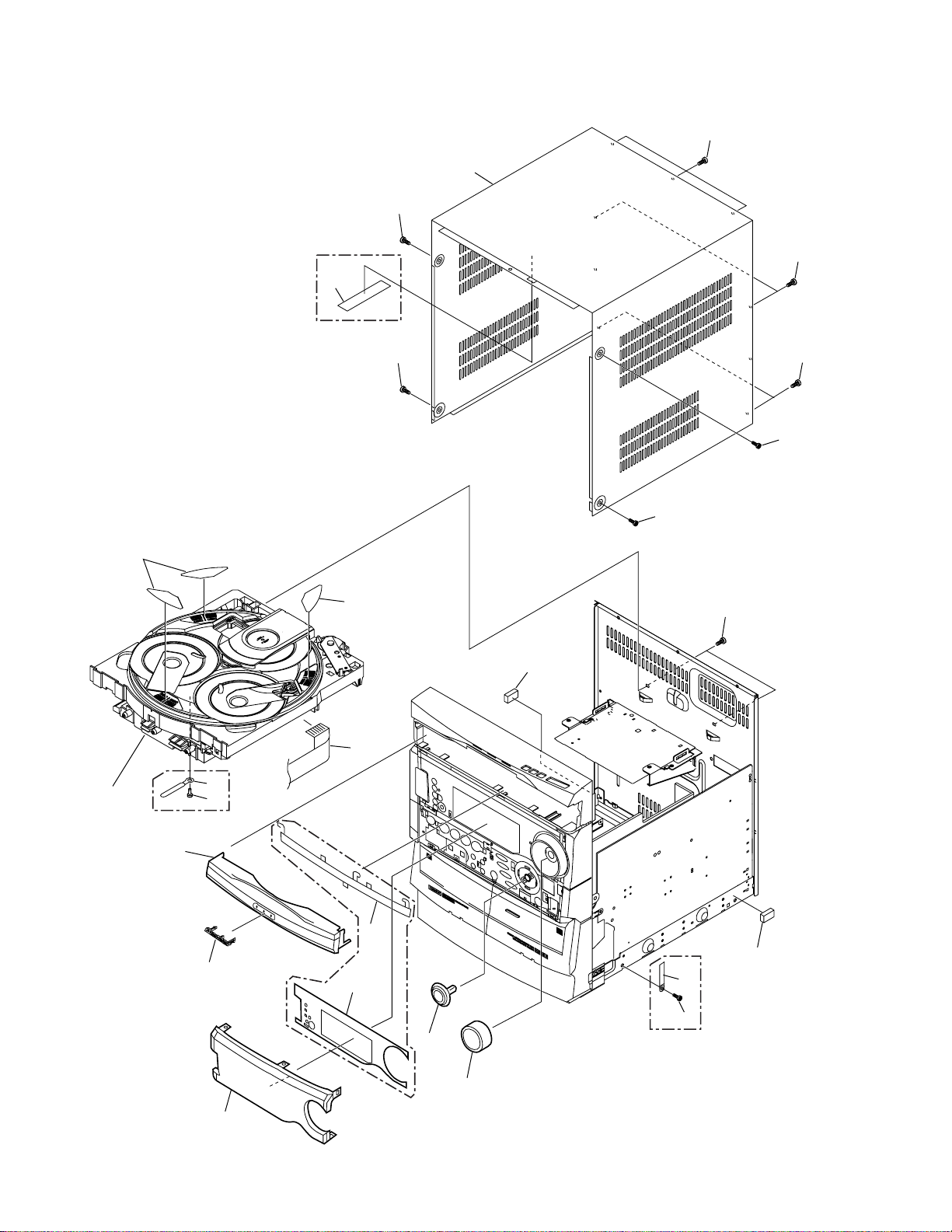
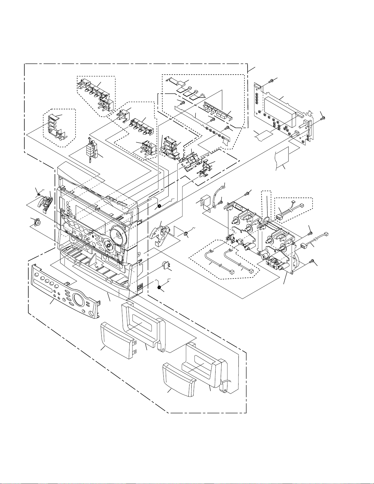
2.2 EXTERIOR (1/2)
Note :
Hook Tray cap on top of loading tray and then
insert the bottom three hooks.
Note :
Attatch on the same numbers × three.
12
21
KUCXJ Type only
11
15
8
9
15
11
9
11
17
10
18
XR-A330
only
2
Refer to
"2.5 $M MECHANISM CD".
6
12
9
19
1
4
19
5
13, 14
16
20
XR-A660 only
3
7
XR-A660 only
6
(1) EXTERIOR (1/2) PARTS LIST
Mark No. Description Part No.
XR-A660, XR-A330
NSP 2 $M Mechanism CD See Contrast table (2)
NSP 17 Cord Stopper See Contrast table (2)
1 F.F.C/30V See Contrast table (2)
3 Volume Knob See Contrast table (2)
4 FL Cover A See Contrast table (2)
5 FL Cover B See Contrast table (2)
6 Tray Cap See Contrast table (2)
7 Display Panel See Contrast table (2)
8 Bonnet Case See Contrast table (2)
9 Screw BPZ30P100FZK
10 Pioneer Badge AZN3049
11 Screw VBT30P080FZK
12 Disc Label XAX3127
13 Jog Knob Assy See Contrast table (2)
14 Jog Knob See Contrast table (2)
15 Screw BCZ30P080FZK
16 Cord Clamper See Contrast table (2)
18 Push Rivet See Contrast table (2)
19 Cushion Rubber XEB3002
20 Screw VBZ30P080FZK
21 65 Label See Contrast table (2)
(2) CONTRAST TABLE
XR-A660/KUCXJ, YPWXJ, XR-A330/KUCXJ and YPWXJ are constructed the same except for the following :
.oNtraP
kraM.oNnoitpircseDdnalobmyS
1V03/C.F.FP228103DDX8103DDXdesutoNdesutoN
1V03/C.F.FP02desutoNdesutoN7103DDX7103DDX
PSN2 DCmsinahceMM$6003AXX6003AXX5003AXX5003AXX
3bonKemuloV5003AAX5003AAX7003AAX7003AAX
4ArevoCLF6203KAX6203KAXdesutoNdesutoN
066A-RX
JXCUK/
066A-RX
JXWPY/
033A-RX
JXCUK/
033A-RX
JXWPY/
skrameR
5BrevoCLF6303KAX6303KAXdesutoNdesutoN
6paCyarT7403NZX7403NZX8403NZX8403NZX
7lenaPyalpsiD9503KAX0203KAX3503KAX0303KAX
8esaCtennoB9303NZX9303NZX5403NZX5403NZX
31yssAbonKgoJ3203GXX3203GXXdesutoNdesutoN
41bonKgoJdesutoNdesutoN8003AAX8003AAX
61repmalCdroC481-HNR481-HNRdesutoNdesutoN
PSN71reppotSdroCdesutoNdesutoN8211FND8211FND
81teviRhsuPdesutoNdesutoN8317CEA8317CEA
12levaL569601WROdesutoN9601WROdesutoN
7
XR-A660, XR-A330
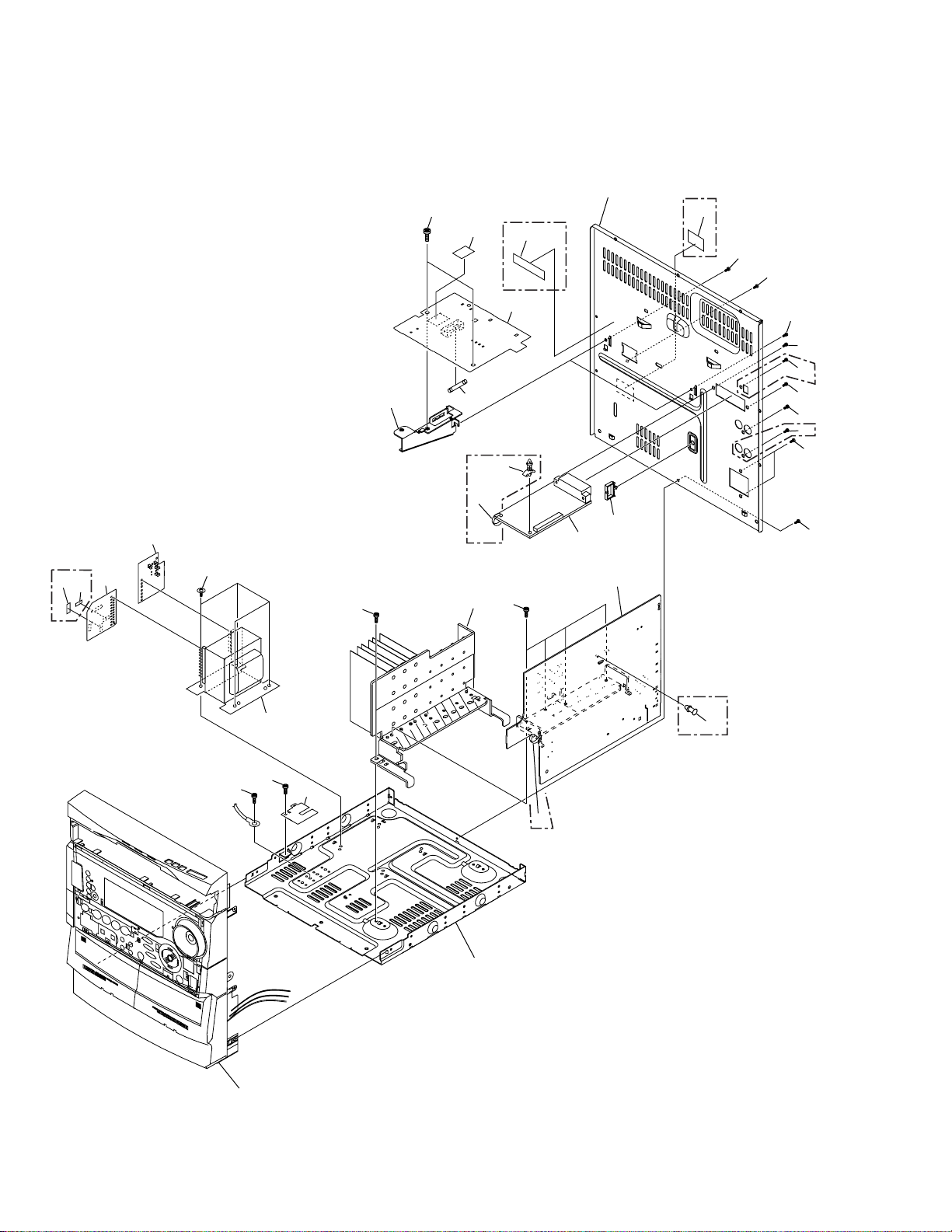
2.3 EXTERIOR (2/2)
XR-A660 only
27
2
28
15
19
11
XR-A330
only
3
21
19
KUCXJ Type only
31
7
22
13
30
29
32
19
14
4
1
YPWXJ Type only
25
19
24
19
24
XR-A660
24
only
24
24
XR-A660
24
only
24
19
5
19
19
Refer to
"2.4 FRONT PANEL SECTION".
17
33
XR-A330
only
22
XR-A660
only
8
8
(1) EXTERIOR (2/2) PARTS LIST
XR-A660, XR-A330
Mark No. Description Part No.
1 AF Assy See Contrast table (2)
2 SECONDARY Assy See Contrast table (2)
3 PRIMARY Assy See Contrast table (2)
4 FM/AM TUNER MODULE AXQ7065
5 T1 Power Transformer See Contrast table (2)
6 • • • • •
7 FU1 Fuse See Contrast table (2)
NSP 8 Chassis XNA3001
9 • • • • •
10 • • • • •
11 PCB Bracket XNG3006
12 • • • • •
13 Heat Sink See Contrast table (2)
14 Wire Clip XEC3002
15 Rear Panel See Contrast table (2)
Mark No. Description Part No.
16 • • • • •
NSP 17 SUPPORT Assy XNP3008
18 • • • • •
19 Screw VBZ30P080FZK
20 • • • • •
21 Screw ASZ40P060FMC
22 Binder ZCA-SKB90BK
23 • • • • •
24 Screw BPZ30P100FZK
25 Caution Label See Contrast table (2)
26 • • • • •
27 ICP Label See Contrast table (2)
28 ICP Label See Contrast table (2)
29 SUB TRANS Assy See Contrast table (2)
30 Fuse Caution Label See Contrast table (2)
NSP 31 Fuse Card See Contrast table (2)
32 Locking Spacer See Contrast table (2)
33 Card Spacer See Contrast table (2)
(2) CONTRAST TABLE
XR-A660/KUCXJ, YPWXJ, XR-A330/KUCXJ and YPWXJ are constructed the same except for the following :
.oNtraP
kraM.oNnoitpircseDdnalobmyS
066A-RX
JXCUK/
066A-RX
JXWPY/
033A-RX
JXCUK/
033A-RX
JXWPY/
skrameR
1yssAFA9803ZWX9803ZWX5403ZWX5403ZWX
2yssAYRADNOCES4803ZWX4803ZWX6403ZWX6403ZWX
3yssAYRAMIRP9503ZWX1503ZWX9503ZWX1503ZWX
5)V021CA(remrofsnarTrewoP1T7103STXdesutoN4103STXdesutoN
5)V042CA(remrofsnarTrewoP1TdesutoN5103STXdesutoN2103STX
7)A5(esuF1UF3801KERdesutoNdesutoNdesutoN
7)A2T(esuF1UFdesutoN7501KEAdesutoNdesutoN
7)A4(esuF1UFdesutoNdesutoN2801KERdesutoN
7)A6.1T(esuF1UFdesutoNdesutoNdesutoN6501KEA
31kniStaeH2003HNX2003HNX3003HNX3003HNX
51lenaPraeR9003CNX4203CNX5103CNX3203CNX
52lebaLnoituaCdesutoN8101WRPdesutoN8101WRP
72lebaLPCI0213XAX0213XAXdesutoNdesutoN
82lebaLPCI1213XAX1213XAXdesutoNdesutoN
92yssASNARTBUS0603ZWX2503ZWX0603ZWX2503ZWX
03lebaLnoituaCesuF2213XAXdesutoN3213XAXdesutoN
PSN13draCesuF7907XAA7532XAA3432XAA7732XAA
23recapSgnikcoLdesutoNdesutoN9003CEX9003CEX
33recapSdraCdesutoNdesutoN8003CEX8003CEX
9
XR-A660, XR-A330
2.4 FRONT PANEL SECTION
XR-A330 only
34
XR-A660 only
26
23
17
21
15
XR-A330 only
25
18
33
24
32
XR-A660 only
34(1/2)
34(2/2)
35
13
XR-A660
only
19
14
17
21
36
16
29
20
1
17
17
9
17
37
6
17
XR-A330 only
25
17
7
8
17
XR-A330 only
38
XR-A660 only
10
5
12
Refer to "2.7 and 2.8
MECHANISM UNIT".
2
17
4
10
27
30
28
31
(1) FRONT PANEL SECTION PARTS LIST
XR-A660, XR-A330
Mark No. Description Part No.
1 DISPLAY Assy See Contrast table (2)
2 CD SW LED Assy See Contrast table (2)
3 • • • • •
4 Connector Assy 2P See Contrast table (2)
5 Connector Assy 3P See Contrast table (2)
NSP 6 Cord With Plug DE007VE0
7 Flexible Cable See Contrast table (2)
8 Flexible Cable 38P XDD3004
9 Connector Assy 3P See Contrast table (2)
10 Connector Assy 5P See Contrast table (2)
11 • • • • •
12 Mechanism Unit See Contrast table (2)
13 Door Spring L XBH3001
14 Door Spring R XBH3002
15 Latch Spring L ABH7130
16 Latch Spring R ABH7131
17 Screw BPZ30P100FZK
18 Latch Mold L XMR3001
19 Latch Mold R XMR3002
20 GND Plate B XNG3005
Mark No. Description Part No.
21 Damper Assy AXA7052
22 • • • • •
NSP 23 Front Panel Assy See Contrast table (2)
24 Function Button See Contrast table (2)
25 CD Button See Contrast table (2)
26 CD Lens See Contrast table (2)
27 Deck Lens L XZN3035
28 Deck Lens R XZN3036
NSP 29 Jog Lens See Contrast table (2)
30 Door Pocket L See Contrast table (2)
31 Door Pocket R See Contrast table (2)
32 Front Panel See Contrast table (2)
33 Sub Panel See Contrast table (2)
34 Power Button See Contrast table (2)
35 Play Button See Contrast table (2)
36 S.C. Button See Contrast table (2)
37 TIMER Button See Contrast table (2)
38 Binder See Contrast table (2)
(2) CONTRAST TABLE
XR-A660/KUCXJ, YPWXJ, XR-A330/KUCXJ and YPWXJ are constructed the same except for the following :
.oNtraP
kraM.oNnoitpircseDdnalobmyS
1yssAYALPSID2903ZWX0113ZWX8503ZWX7403ZWX
2yssADELWSDC6803ZWX6803ZWXdesutoNdesutoN
4P2yssArotcennoCdesutoNdesutoN2103EDX2103EDX
5P3yssArotcennoCdesutoNdesutoN1103EDX1103EDX
7P91elbaCelbixelF9003DDX9003DDXdesutoNdesutoN
7P71elbaCelbixelFdesutoNdesutoN0103DDX0103DDX
9P3yssArotcennoC1003EDX1003EDX9003EDX9003EDX
01P5yssArotcennoC2003EDX2003EDXdesutoNdesutoN
21tinUmsinahceM3003MYX3003MYX2003MYX2003MYX
PSN32yssAlenaPtnorF4103GXX4103GXX1103GXX1103GXX
42nottuBnoitcnuF0203NZX0203NZX1203NZX1203NZX
52nottuBDC8103NZX8103NZX9103NZX9103NZX
62sneLDC7303NZX7303NZXdesutoNdesutoN
PSN92sneLgoJ5203KAX5203KAXdesutoNdesutoN
03LtekcoProoD3103NZX3103NZX4103NZX4103NZX
13RtekcoProoD5103NZX5103NZX6103NZX6103NZX
23lenaPtnorF1103NZX1103NZX2103NZX2103NZX
33lenaPbuS1303NZX1303NZX3303NZX3303NZX
43nottuBrewoP2203NZX2203NZX3203NZX3203NZX
53nottuByalP4203NZX4203NZXdesutoNdesutoN
63nottuB.C.S5203NZX5203NZX7203NZX7203NZX
73nottuBREMIT9203NZX9203NZX0303NZX0303NZX
83redniBdesutoNdesutoNKB09BKS-ACZKB09BKS-ACZ
066A-RX
JXCUK/
066A-RX
JXWPY/
033A-RX
JXCUK/
033A-RX
skrameR
JXWPY/
11
XR-A660, XR-A330
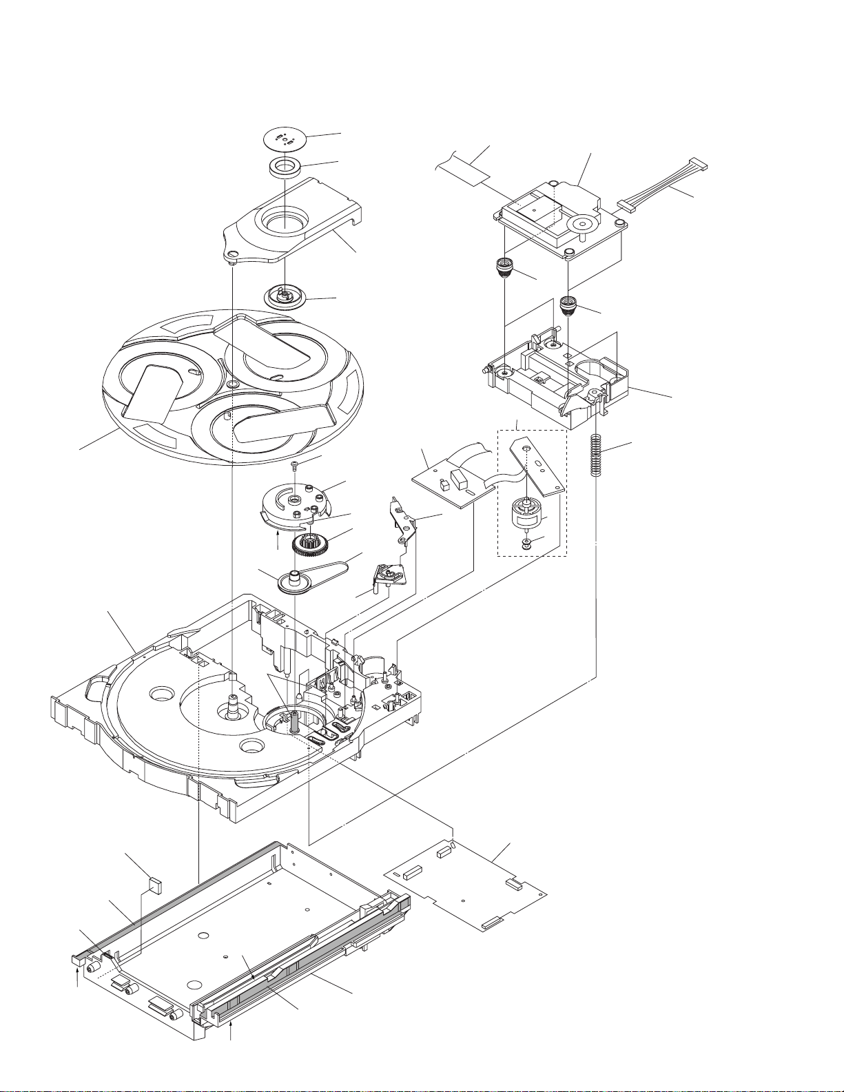
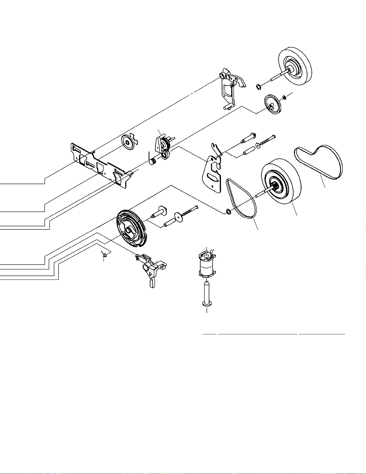
2.5 $M MECHANISM CD
13
8
21
7
14
1
Refer to "2.6 SERVO MECHANISM ASSY".
25
22
24
23
11
12
10
30
16
29
29
26
17
15
29
18
2
19
6
27
28
3
5
12
29
29
29
29
9
29
29
$M MECHANISM CD PARTS LIST
•
Mark No. Description Part No.
1 MOTOR Assy AWZ8428
NSP 2 SW Assy AWZ8429
3 CD Assy (XR-A660) XWZ3141
3 CD Assy (XR-A330) XWZ3050
4 • • • • •
5 Servo Spring ABH7126
6 Belt AEB7072
7 Clamp Magnet AMF7001
8 Yoke ANB7067
9 Mecha Base ANW7125
10 Loading Tray ANW7088
11 Servo Base ANW7089
12 Rotary Tray ANW7113
13 Clamper ANW7091
14 Clamper Holder ANW7092
15 Main Cam ANW7093
XR-A660, XR-A330
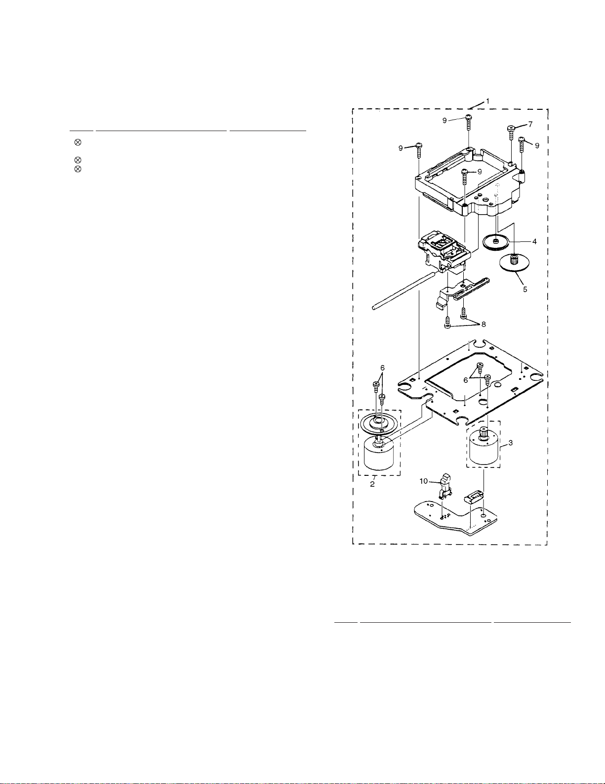
2.6 SERVO MECHANISM ASSY
16 Gear Pully ANW7094
17 Lock Lever ANW7095
18 Planet Gear ANW7096
19 Actuater ANW7097
20 • • • • •
21 15P F.F.C/30V ADD7038
22 Connector Assy (6P) ADE7010
23 Float Rubber A AEB7063
24 Float Rubber B AEB7066
25 Servo Mechanism Assy AXA7039
26 Screw IPZ30P080FMC
27 Carriage Motor VXM1033
28 Motor Pulley PNW1634
29 Ha Narl GEM1016
30 Cushion Rubber XEB3003
SERVO MECHANISM ASSY PARTS LIST
•
Mark No. Description Part No.
1 Servo Mechanism AXA7039
2 SPINDLE MOTOR Assy AEA7009
3 SLEAD MOTOR Assy AEA7010
4 Gear A AEA7013
5 Gear B AEA7014
6 Screw AEA7015
7 Screw AEA7016
8 Screw AEA7017
9 Screw AEA7018
10 Leaf Switch AEA7011
13
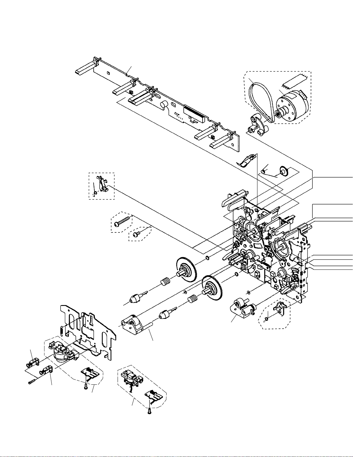
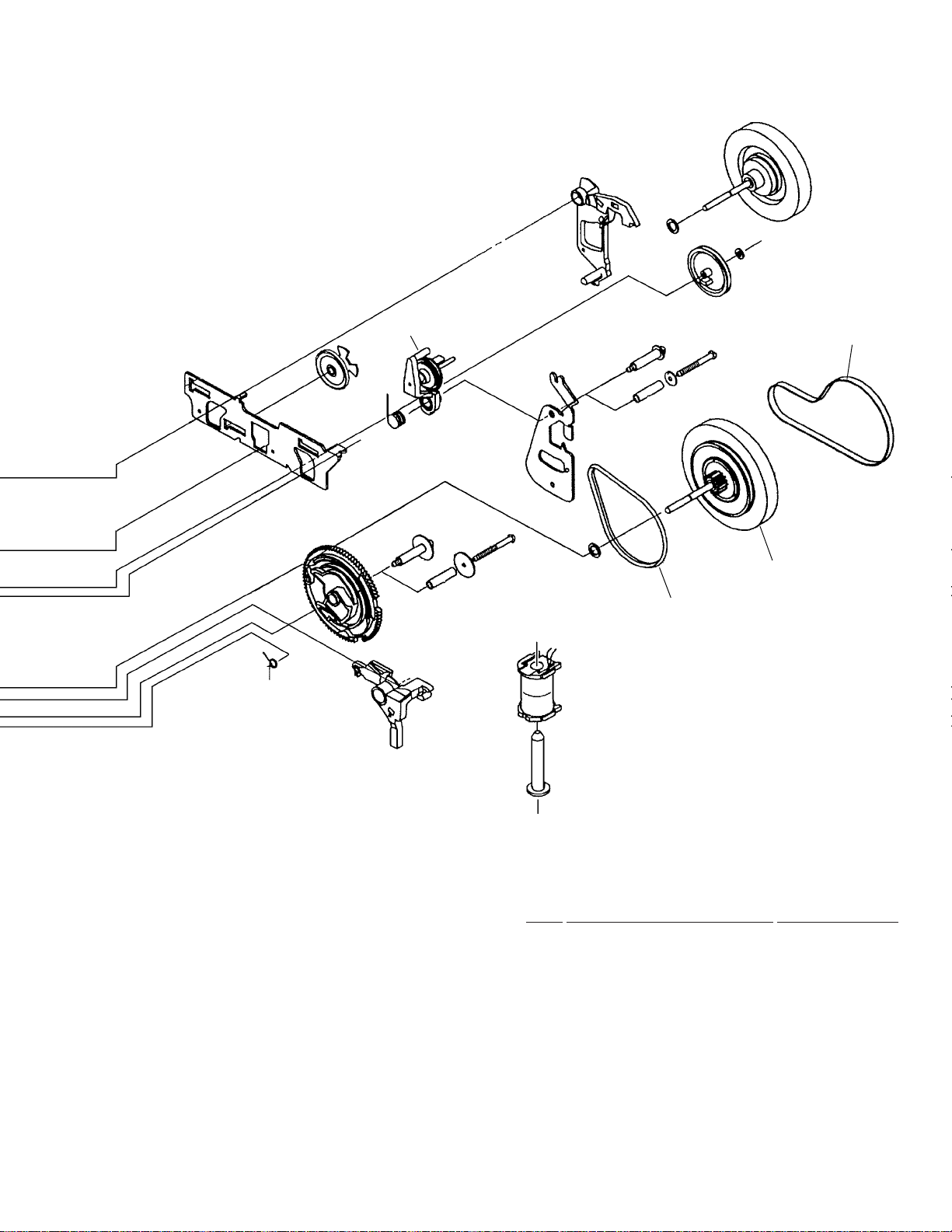
XR-A660, XR-A330
2.7 MECHANISM UNIT (XR-A660)
Mech. Ι
Only
Mech. ΙΙ
4
Mech. ΙΙ
Only
7
3
12
Mech. Ι
13
Mech. Ι
9
Mech. ΙΙ
Only
10
1
2
Mech. ΙΙ
14
XR-A660, XR-A330
5
8
11
6
MECHANISM UNIT PARTS LIST
•
Mark No. Description Part No.
1 Plate HD BLK (Mech. Ι) F513-819
2 Plate HD BLK (Mech. ΙΙ) F513-811
3 Motor Main BLK (Mech. ΙΙ only) F525-324
4 PCB Control BLK F567-621
5 Clutch Assy BLK F522-037
6 Main Belt FF17G-31
7 Joint Belt 113 (Mech. ΙΙ only) FF19D-21
8 Clutch Assy BLK F522-045
9 Roller Pinch BLK R F514-129
10 Roller Pinch BLK L F514-130
11 F/R Belt FF18W-12
12 Plate Base BLK F512-127
13 Plate Base BLK F512-128
15
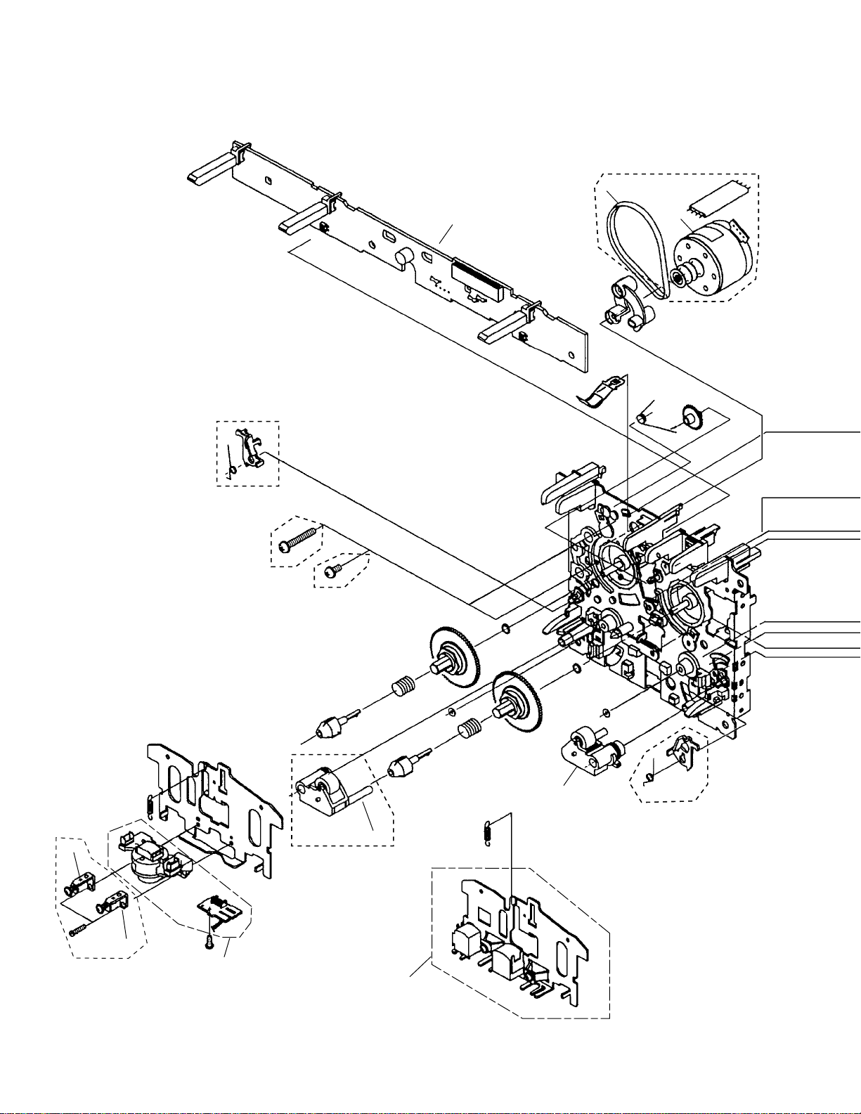
XR-A660, XR-A330
2.8 MECHANISM UNIT (XR-A330)
Mech. ΙΙ
Only
6
Mech. Ι
Only
Mech. ΙΙ
Mech. Ι
4
3
12
Mech. ΙΙ Only
16
Mech. ΙΙ
9
Mech. ΙΙ
Only
10
Mech. ΙΙ
Only
13
1
2
Mech. Ι
XR-A660, XR-A330
5
8
11
MECHANISM UNIT PARTS LIST
•
Mark No. Description Part No.
1 Plate HD BLK (Mech. ΙΙ) F513-811
2 Plate HD BLK (Mech. Ι) F513-825
3 Motor Main BLK (Mech. ΙΙ only) F525-324
4 PCB Control BLK F567-622
5 Clutch Assy BLK F522-037
6
6 Main Belt FF17G-31
7 • • • • •
8 Clutch Assy BLK (Mech. ΙΙ) F522-045
8 Clutch Assy BLK (Mech. Ι) F522-038
9 Roller Pinch BLK R (Mech. ΙΙ) F514-129
9 Roller Pinch BLK R (Mech. Ι) F514-131
10 Roller Pinch BLK L (Mech. ΙΙ only) F514-130
11 F/R Belt FF18W-12
12 Plate Base BLK (Mech. ΙΙ only) F512-127
13 Plate Base BLK (Mech. ΙΙ only) F512-128
17
1
XR-A660, XR-A330
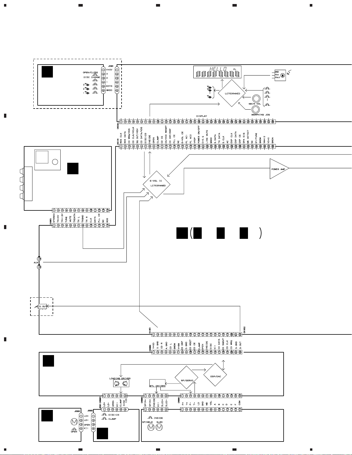
3. SCHEMATIC DIAGRAM
3.1 OVERALL WIRING DIAGRAM
A
J
CD SW LED
ASSY
(XWZ3086)
XR-A660 ONLY
23
4
B
C
A
FM/AM TUNER
MODULE
(AXQ7065)
CN6201
XR-A660 ONLY
E
E
AF ASSY
(XR-A660 : XWZ3089)
(XR-A330 : XWZ3045)
E E
1/3, 3/3
2/3,
CD ASSY
B
(XR-A660 : XWZ3141)
(XR-A330 : XWZ3050)
D
CARRIAGE
C
18
MOTOR
ASSY
(AWZ8428)
1234
SW ASSY
D
(AWZ8429)
SERVO MECHANISM ASSY
(AXA7039)
5
678
XR-A660, XR-A330
Note : When ordering service parts, be sure to refer to "EXPLODED VIEWS and P AR TS LIST" or "PCB PARTS LIST".
I
DISPLAY ASSY
(XR-A660/KUCXJ : XWZ3092)
(XR-A660/YPWXJ : XWZ3110)
(XR-A330/KUCXJ : XWZ3058)
(XR-A330/YPWXJ : XWZ3047)
AEK7071
XR-A660 ONLY
XR-A660 ONLY
XR-A660 ONLY
A
B
F
SECONDARY
ASSY
(XR-A660 : XWZ3084)
(XR-A330 : XWZ3046)
G
PRIMARY ASSY
(KUCXJ Type: XWZ3059)
(YPWXJ Type: XWZ3051)
YPWXJ TYPE
KUCXJ TYPE
H
SUB TRANS ASSY
(KUCXJ Type: XWZ3060)
(YPWXJ Type: XWZ3052)
C
KUCXJ
TYPE
ONLY
D
19
5
6
7
8
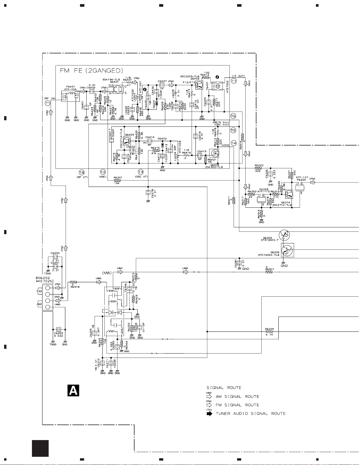
1
RF AMP
1T378A
1T378A
MIX AMP
BUFFER
IF AMP
FM +B SW
MW RF TUNING BLOCK
AKX7041
OSC
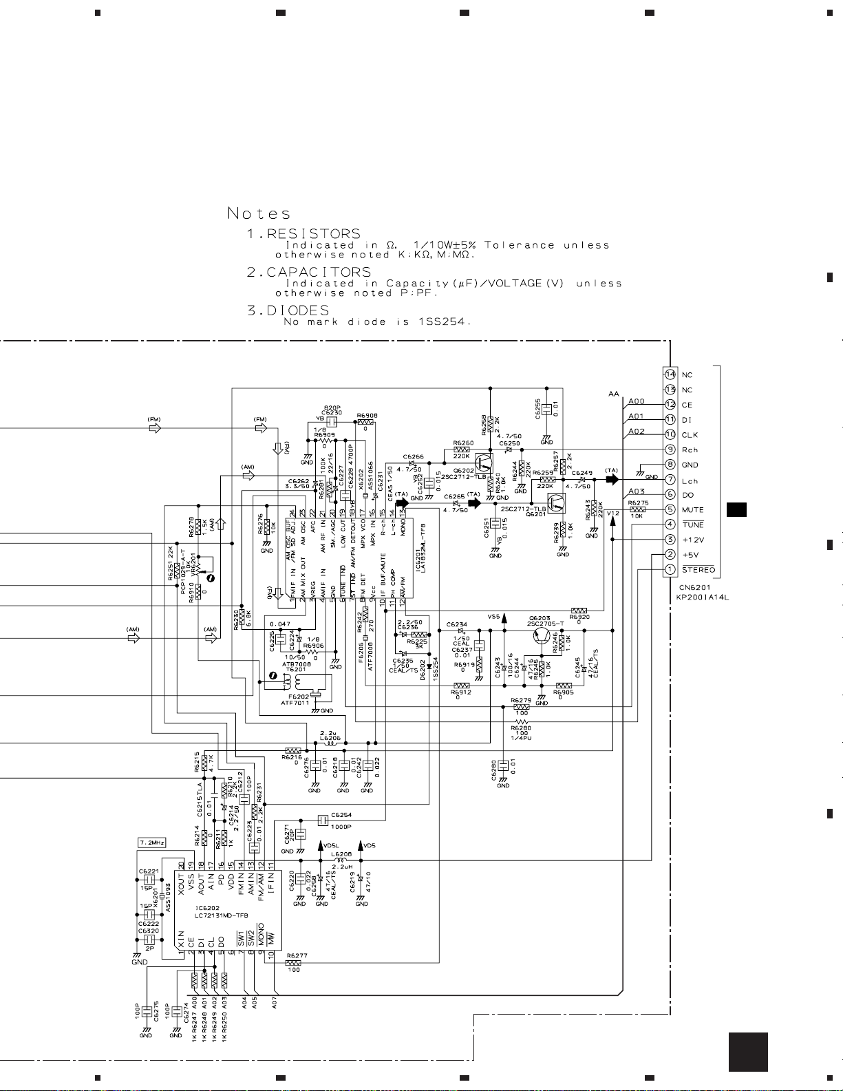
FM/AM TUNER MODULE
(AXQ7065)
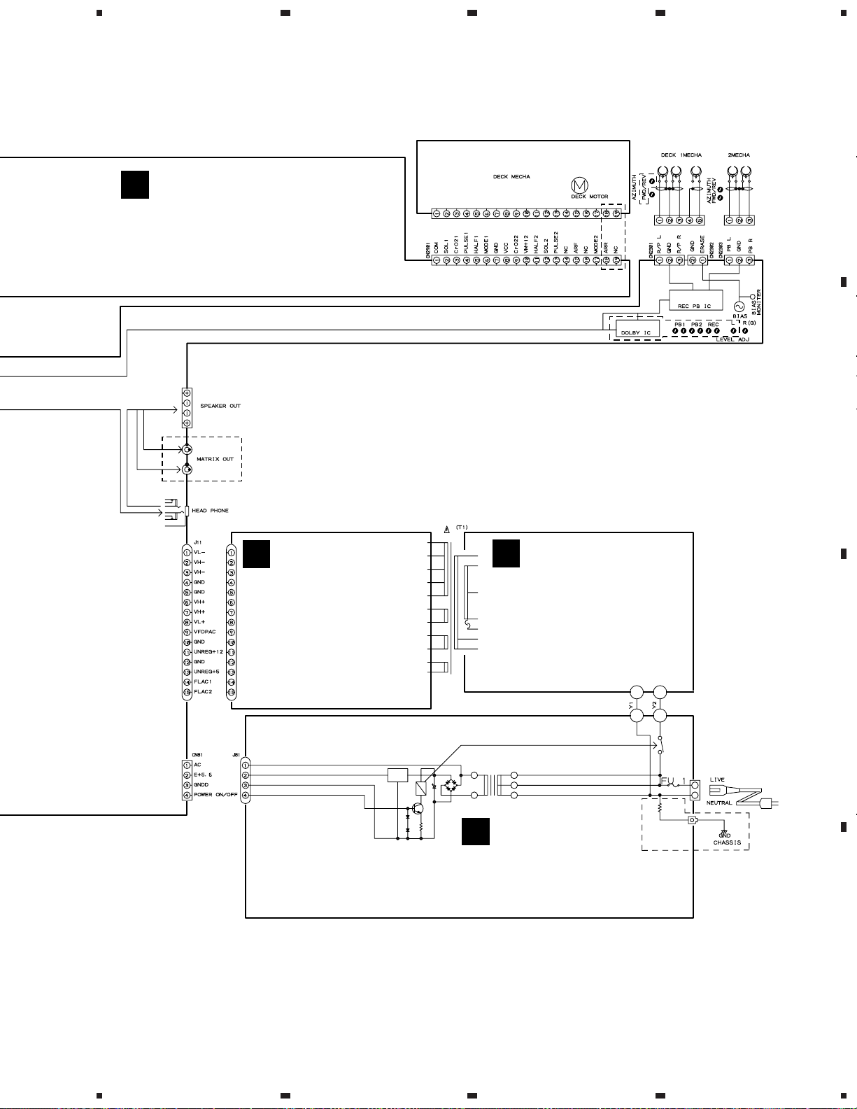
XR-A660, XR-A330
3.2 FM/AM TUNER MODULE
A
23
4
B
C
D
20
A
1234
5
678
XR-A660, XR-A330
A
B
AF AMP
AF AMP
REGULATOR
CN3051
2/3E
C
PLL
D
A
5
6
7
8
21
1
23
XR-A660, XR-A330
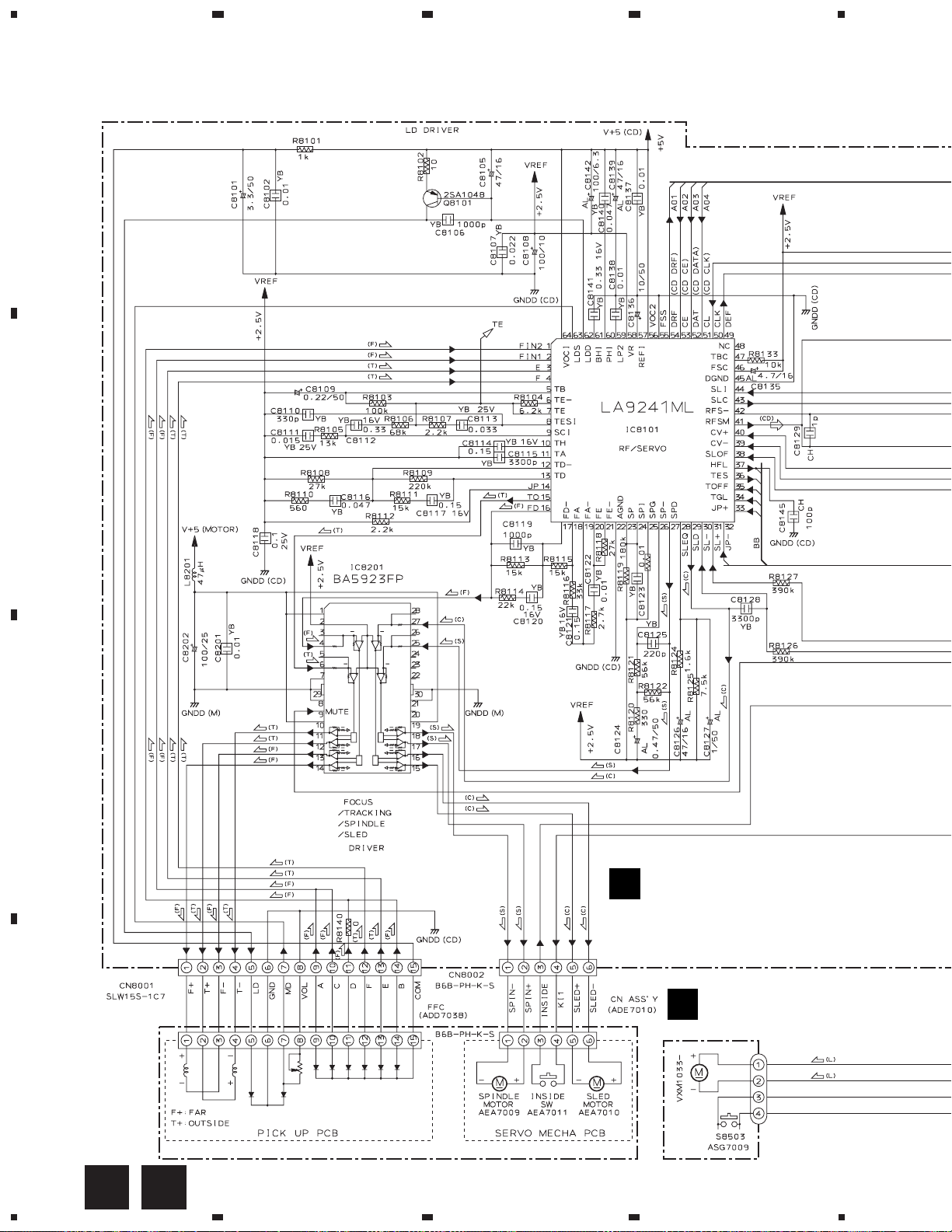
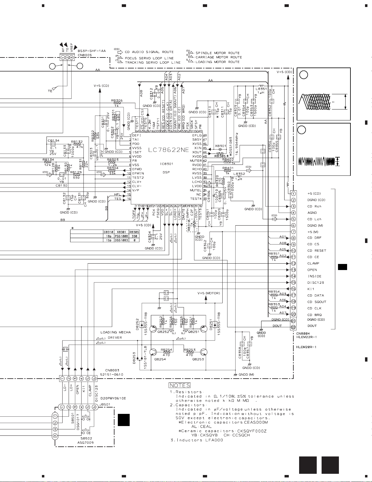
3.3 CD, MOTOR and SW ASSEMBLIES
A
B
4
56k
R8123
C
CD ASSY
B
(XR-A660 : XWZ3141)
(XR-A330 : XWZ3050)
MOTOR ASSY
C
(AWZ8428)
CARRIAGE MOTOR
D
22
B C
J8502
SERVO MECHANISM ASSY AXA7039
1234
D20PWW0405E
5
678
XR-A660, XR-A330
Note: The encircled numbers
denote measuring point in the
1
2
schematic diagram.
CN8005- Pin 1 :
1
PLAY MODE (RF)
H : 500nsec/div
1.8Vp-p
A
XR-A660, XR-A550
XR-A330
XR-A660,
XR-A550
Only
C8308
1000p
C8307
1000p
YB
YB
C8371
100/10
0.047
CN8005- Pin 2 :
2
TEST MODE,
Tracking Open(TRER)
H : 5msec/div
VREF:CN8005- Pin3
L8371 47µH
VREF
1.0Vp-p
VREF
B
CN1051
2/3E
J8502
C8257
0.1
C8256 0.1
C8255 0.1
2SB1237X 2SB1237X
2SD1858X
2SD1858X
0.047
(XR-A660, XR-A550)
(XR-A330)
C
D
D
SW ASSY
(AWZ8429)
B D
5
6
7
8
23
1
XR-A660, XR-A330
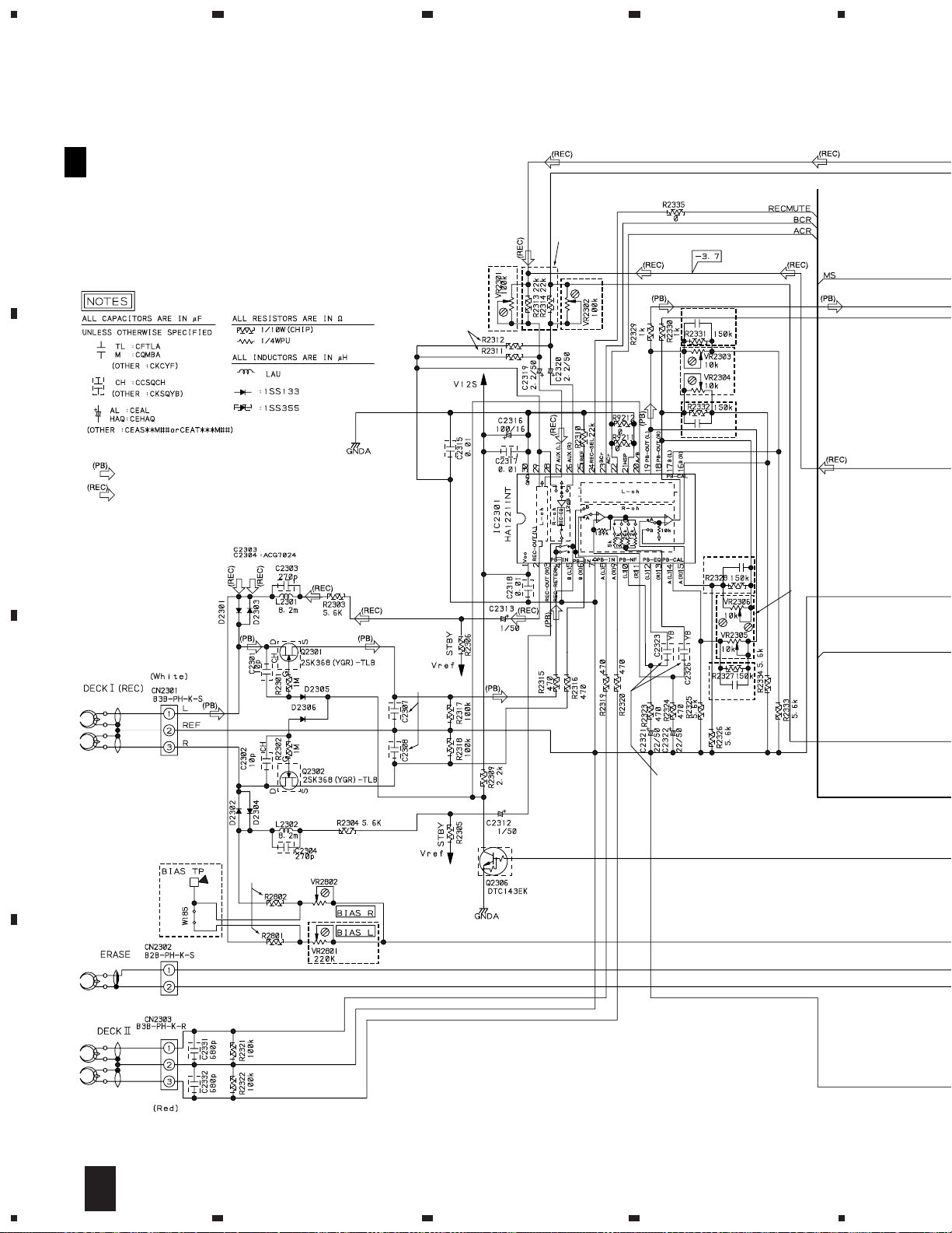
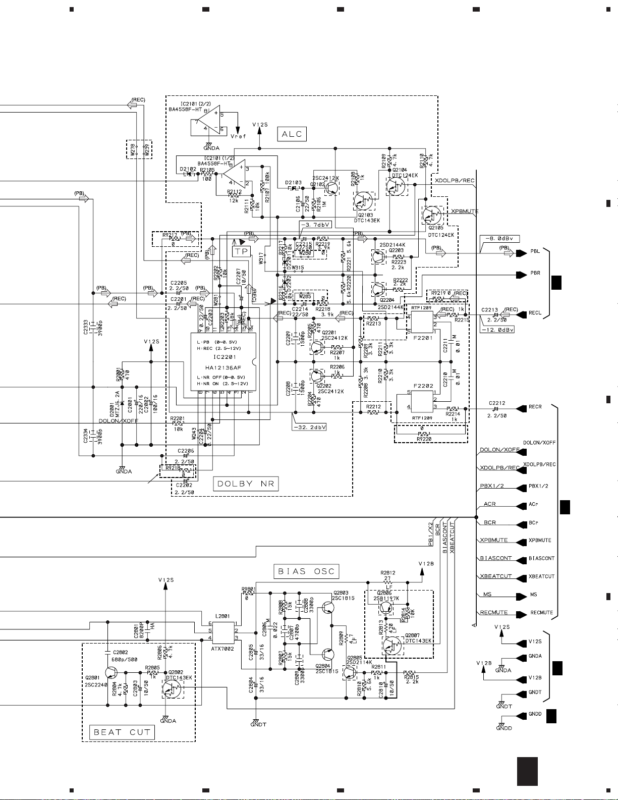
3.4 AF ASSY (1/3)
23
4
A
E
AF ASSY
1/3
(XR-A660 : XWZ3089)
(XR-A330 : XWZ3045)
XR-A660
ONLY
22k(XR-A660)
39k(XRA330)
B
: DECK PB SIGNAL ROUTE
: DECK REC SIGNAL ROUTE
XR-A330
ONLY
XR-A660
ONLY
C2335 27p
C2336 27p
XR-A330
ONLY
C2337 27p
XR-A330
ONLY
XR-A660
ONLY
XR-A330
ONLY
XR-A660
ONLY
680p(XR-A660)
1000p(XR-A330)
C
XR-A330
ONLY
D
33k(XR-A660)
47k(XR-A330)
220k(XR-A660)
100k(XR-A330)
XR-A660
ONLY
0.022(XR-A660)
0.027(XR-A330)
C2338 27p
XR-A330
ONLY
24
1/3
E
1234
XR-A330
ONLY
5
XR-A330
ONLY
678
XR-A660, XR-A330
A
XR-A330
ONLY
XR-A330
ONLY
XR-A330
ONLY
E
2/3
B
XR-A330
ONLY
22k(XR-A660)
0(XR-A330)
22k(XR-A660)
0(XR-A330)
XR-A330
ONLY
XR-A660 ONLY
E
C
2/3
XR-A660 ONLY
XR-A660
ONLY
E
5
6
7
3/3
E
2/3
E
1/3
8
D
25
 Loading...