

Pioneer VSXLX304 Instruction Manual
Instruction
En
Manual
Table of contents ≫
Connections ≫
VSX-LX304
AV RECEIVER
- Connecting Speakers ≫
Playback ≫
Setup ≫
Troubleshooting ≫
Appendix ≫
Supplementary Information ≫
Front Panel≫ Rear Panel≫ Remote≫
Contents ≫ Connections ≫ Playback ≫ Setup
≫
What’s in the box 5
Additional Function (Firmware Update) 6
Update Information of the rmware 6
Operation of added new functions 6
Firmware Update Procedure 7
Part Names 10
Front Panel 10
Display 12
Rear Panel 13
Remote Controller 15
Connections
Connecting speakers 18
Speaker Installation 19
Speaker Connections and "Speaker Setup" Settings 37
Speaker combinations 50
Connecting the TV 51
To ARC TV 52
To Non-ARC TV 53
Connecting Playback Devices 54
Connecting an AV Component with HDMI Jack
Mounted 54
Connecting an AV Component in a Separate Room
(Multi-zone Connection) 57
Connecting a TV (ZONE 2) 57
Connecting a Pre-main Amplier (ZONE 2) 58
Connecting ZONE B 59
Connecting a Pre-main Amplier, etc. (ZONE B) 59
Connecting Antennas 60
Network Connection 61
Connecting External Control Devices 62
IR IN/OUT port 62
12V TRIGGER OUT jack 63
Connecting the Power Cord 64
Playback
AV Component Playback 66
Basic Operations 66
BLUETOOTH® Playback 67
Basic Operations 67
Internet Radio 68
Playing Back 68
Spotify 70
AirPlay® 71
Connecting an Audio Component 55
Connecting a Video Camera, etc. 56
Playing Back on This Unit 71
Playing Back on multiple devices (AirPlay2) 72
2
Front Panel≫ Rear Panel≫ Remote≫
Contents ≫ Connections ≫ Playback ≫ Setup
≫
DTS Play-Fi® 73
Playing Back 73
FlareConnectTM 74
Playing Back 74
USB Storage Device 75
Basic Operations 75
Device and Supported Format 77
Playing back les on a PC and NAS (Music Server) 78
Windows Media® Player settings 78
Playing Back 79
Supported Audio Formats 82
Play Queue 83
Initial Setup 83
Adding Play Queue Information 83
Sort and Delete 84
Playing Back 84
Amazon Music 85
Playing Sonos on This Unit 87
Listening To the AM/FM Radio 88
Tuning into a Radio Station 88
Presetting a Radio Station 90
Using RDS (European, Australian and Asian models) 92
Multi-zone 93
Playing Back (ZONE 2) 94
Playing Back (ZONE 3) 96
ZONE B Playback 97
Playing Back 97
Convenience functions 98
Using PERSONAL PRESET 98
Adjusting the tone 100
Sleep Timer 102
Listening Mode 103
Selecting a Listening mode 103
Speaker Layouts and Selectable Listening Modes 106
Registering this unit with Amazon Music 85
Playing Amazon Music 85
Connecting the Sonos System for Playback 86
Necessary Equipment 86
How to Connect This Unit and Sonos Connect 86
Setting Up 86
Listening Mode Eects 109
Input Formats and Selectable Listening Modes 113
Inputting Characters 119
3
Front Panel≫ Rear Panel≫ Remote≫
Contents ≫ Connections ≫ Playback ≫ Setup
≫
Setup
System Setup 120
Menu list 120
Menu operations 122
Input/Output Assign 123
Speaker 127
Audio Adjust 132
Source 134
Hardware 136
Multi Zone 144
Miscellaneous 145
Advanced MCACC 147
Menu operations 147
Full Auto MCACC 148
Manual MCACC 149
MCACC Data Check 151
Network/Bluetooth 152
Web Setup 158
Menu operations 158
Initial Setup with Auto Start-up Wizard 159
Operations 159
Troubleshooting
When the unit is operating erratically 163
Troubleshooting 165
Appendix
Reducing the Power Consumption in Standby State 174
About HDMI 175
General Specications 177
Menu operations 152
Network 153
Bluetooth 155
AV Adjust 156
Menu operations 156
4
Front Panel≫ Rear Panel≫ Remote≫
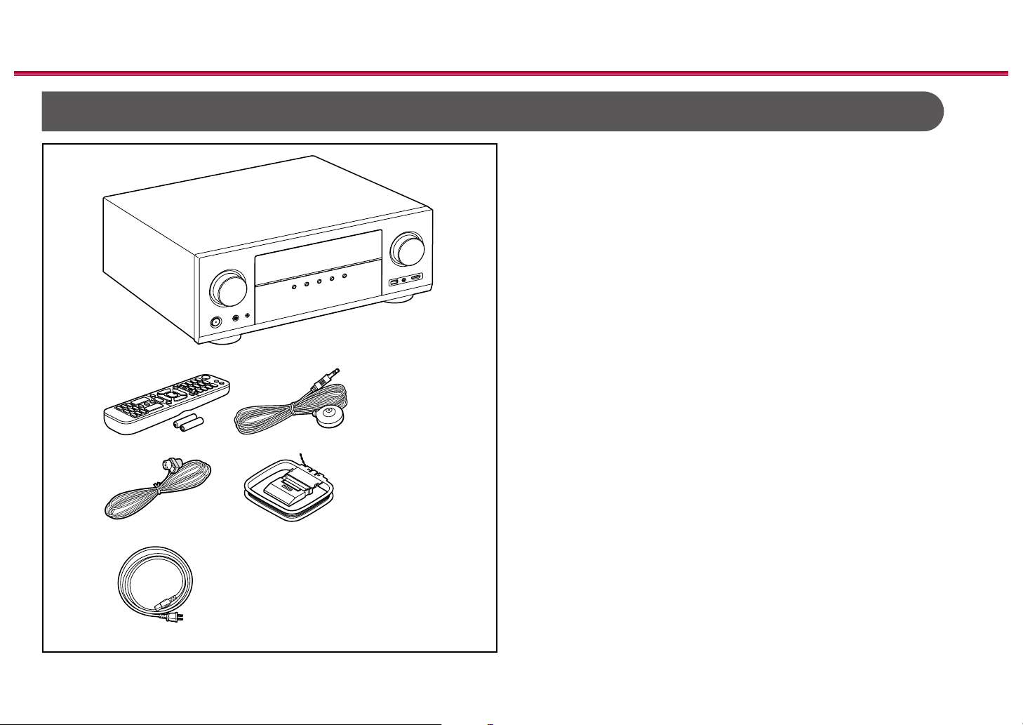
What’s in the box
1
32
54
Contents ≫ Connections ≫ Playback ≫ Setup
1. Main unit (1)
2. Remote controller (RC-974R) (1), Batteries (AAA/R03) (2)
3. Speaker setup microphone (1)
• Used during Initial Setup.
4. Indoor FM antenna (1)
5. AM loop antenna (1)
6. Power cord (1)
• Quick Start Guide (1)
* This document is an online instruction manual. It is not included as an
accessory.
• Connect speakers with an impedance of 4 Ω to 16 Ω.
• The power cord must be connected only after all other connections are
completed.
• We will not accept any responsibility for damage arising from the connection
with equipment manufactured by other companies.
• Network services and content that can be used may no longer be available
if new functions are added by updating rmware or the service providers
terminate their services. Also, available services may dier depending on your
area.
• Details on the rmware update will be posted on our website and through
other means at a later date.
• Specications and appearance are subject to change without prior notice.
≫
6
5
Front Panel≫ Rear Panel≫ Remote≫
Contents ≫ Connections ≫ Playback ≫ Setup
Additional Function (Firmware Update)
This unit is equipped with a function to update the rmware via network or USB port when the rmware update is announced after purchase. This enables various
functions to be added and operations to be improved.
Depending on the manufacturing timing of the product, the rmware may be switched to the updated one. In such a case, new functions may be added from the start.
For how to conrm the latest rmware contents and the rmware version of your product, see the following section.
Update Information of the rmware
For the latest rmware contents and the rmware version, visit our company’s website. If the rmware version of your product diers from the latest one, it is
recommended to update the rmware.
To conrm the rmware version of your product, press the button on the remote controller to display the Home screen, and refer to "System Setup" - "Miscellaneous"
- "Firmware Update" - "Version" ( p145).
Operation of added new functions
If functions are added or changed from contents described in the Instruction Manual, see the following reference.
Supplementary Information ≫
≫
❏ Firmware Update Procedure ( p7)
6
Front Panel≫ Rear Panel≫ Remote≫
Firmware Update Procedure
Contents ≫ Connections ≫ Playback ≫ Setup
≫
The update may take approx. 20 minutes to complete via network or via USB
port. Existing settings are guaranteed in either updating method.
When this unit is connected to the network, notications of rmware updates may
be displayed. To update the rmware, select "Update Now" with the cursors on
the remote controller, and press the ENTER button. The unit automatically enters
standby mode after "Completed!" is displayed, and the update is completed.
Disclaimer: The program and accompanying online documentation are furnished
to you for use at your own risk.
Our company will not be liable and you will have no remedy for damages for
any claim of any kind whatsoever concerning your use of the program or the
accompanying online documentation, regardless of legal theory, and whether
arising in tort or contract.
In no event will our company be liable to you or any third party for any special,
indirect, incidental, or consequential damages of any kind, including, but not
limited to, compensation, reimbursement or damages on account of the loss of
present or prospective prots, loss of data, or for any other reason whatsoever.
Updating the Firmware via Network
• While updating the rmware, do not do the following:
– Disconnecting and reconnecting cables, USB storage device, speaker
setup microphone or headphones, or performing operations on the unit
such as turning the power o
– Accessing this unit from a PC or smartphone using their applications
• Check that the unit is turned on, and the connection to the Internet is secured.
• Turn o the controller components (PC etc.) connected to the network.
• Stop any playing Internet radio, USB storage device, or server content.
• If the multi-zone function is active, turn it o.
• If "HDMI CEC" is set to "On", set it to "O".
– Press to display the Home screen. Next, select "System Setup" -
"Hardware" - "HDMI", press ENTER, select "HDMI CEC" and select "O".
* The descriptions may dier from the actual on-screen displays, however, operations
and functions are the same.
Update
1. Press .
The Home screen is displayed on the TV screen.
2. Select "System Setup" - "Miscellaneous" - "Firmware Update" - "Update via
NET" with the cursors in order, then press ENTER.
• If "Firmware Update" is grayed out and cannot be selected, wait for a while
until it starts up.
• If there is no updatable rmware, "Update via NET" cannot be selected.
3. Press ENTER with "Update" selected, and start update.
• During the update, the TV screen may go black depending on the program
to be updated. In such a case, check the progress on the display of the
unit. The TV screen will remain black until the update is completed and the
power is turned on again.
• When "Completed!" is displayed, the update is complete.
4. Press STANDBY/ON on the main unit to turn the unit into standby mode.
The process is completed, and your rmware is updated to the latest version.
• Do not use on the remote controller.
7
Front Panel≫ Rear Panel≫ Remote≫

Contents ≫ Connections ≫ Playback ≫ Setup
≫
If an Error Message is Displayed
If an error occurs, "- Error!" is displayed on the display of the unit. (""
represents an alphanumeric character.) Refer to the following descriptions and
check.
Error Code
• -01, -10:
LAN cable not found. Connect the LAN cable properly.
• -02, -03, -04, -05, -06, -11, -13, -14, -16, -17, -18, -20,
-21:
Internet connection error. Check the following:
– Whether the router is turned on
– Whether this unit and the router are connected via the network
Unplug and plug the power cords of this unit and the router. This may solve
the problem. If you are still unable to connect to the Internet, the DNS server
or proxy server may be temporarily down. Check the server operation status
with your Internet service provider.
• Others:
After removing the power plug once, insert it to the outlet, and then start the
operation from the beginning.
Updating via USB
• While updating the rmware, do not do the following:
– Disconnecting and reconnecting cables, USB storage device, speaker
setup microphone or headphones, or performing operations on the unit
such as turning the power o
– Accessing this unit from a PC or smartphone using their applications
• Prepare a 256 MB or larger USB storage device. The format of USB storage
devices supports FAT16 or FAT32 le system format.
– Media inserted into a USB card reader may not be used for this function.
– USB storage devices equipped with the security function are not supported.
– USB hubs and USB devices equipped with the hub function are not
supported. Do not connect these devices to the unit.
• Delete any data stored on the USB storage device.
• Turn o control devices (PC etc.) connected to the network.
• Stop an Internet radio, USB storage device, or server content being played.
• If the multi-zone function is active, turn it o.
• If "HDMI CEC" is set to "On", set it to "O".
– Press to display the Home screen. Next, select "System Setup" -
"Hardware" - "HDMI", press ENTER, select "HDMI CEC" and select "O".
* Depending on the USB storage device or its content, long time may be required
for loading, the content may not be loaded correctly, or power may not be supplied
correctly.
* Our company will not be liable whatsoever for any loss or damage of data, or storage
failure arising from the use of the USB storage device. Please note this in advance.
* The descriptions may dier from the actual on-screen displays, however, operations
and functions are the same.
Update
1. Connect the USB storage device to your PC.
2. Download the rmware le from our company's website to your PC and unzip.
Firmware les are named as below.
PIOAVR_R.zip
Unzip the le on your PC. The number of unzipped les and folders varies
depending on the model.
3. Copy all unzipped les and folders to the root folder of the USB storage
device.
• Make sure to copy the unzipped les.
4. Connect the USB storage device to the USB port of this unit.
• If an AC adapter is supplied with the USB storage device, connect the AC
adapter, and use it with a household outlet.
• If the USB storage device has been partitioned, each section will be treated
as an independent device.
5. Press .
The Home screen is displayed on the TV screen.
8
Front Panel≫ Rear Panel≫ Remote≫

Contents ≫ Connections ≫ Playback ≫ Setup
≫
6. Select "System Setup" - "Miscellaneous" - "Firmware Update" - "Update via
USB" with the cursors in order, then press ENTER.
• If "Firmware Update" is grayed out and cannot be selected, wait for a while
until it starts up.
• If there is no updatable rmware, "Update via USB" cannot be selected.
7. Press ENTER with "Update" selected, and start update.
• During the update, the TV screen may go black depending on the program
to be updated. In such a case, check the progress on the display of the
unit. The TV screen will remain black until the update is completed and the
power is turned on again.
• During the update, do not turn the power o, or disconnect or reconnect the
USB storage device.
• When "Completed!" is displayed, the update is complete.
8. Disconnect the USB storage device from the unit.
9. Press STANDBY/ON on the main unit to turn the unit into standby mode.
The process is completed, and your rmware is updated to the latest version.
• Do not use on the remote controller.
If an Error Message is Displayed
If an error occurs, "- Error!" is displayed on the display of the unit. (""
represents an alphanumeric character.) Refer to the following descriptions and
check.
Error Code
• -01, -10:
The USB storage device cannot be recognized. Check if the USB storage
device or USB cable is securely inserted to the USB port of the unit.
Connect the USB storage device to an external power source if it has its own
power supply.
• -05, -13, -20, -21:
The rmware le is not present in the root folder of the USB storage device, or
the rmware le is for another model. Retry from the download of the rmware
le.
• Others:
After removing the power plug once, insert it to the outlet, and then start the
operation from the beginning.
9
Front Panel≫ Rear Panel≫ Remote≫

Part Names
Front Panel
Contents ≫ Connections ≫ Playback ≫ Setup
≫
❏ For details, see ( p11)
10
Front Panel≫ Rear Panel≫ Remote≫

Contents ≫ Connections ≫ Playback ≫ Setup
≫
1. INPUT SELECTOR dial: Switch the input to be played.
2. FL OFF indicator: Lights up when the display is turned o by repeatedly
pressing the DIMMER button on the remote controller.
3. ZONE 2 ON/OFF button: Turns ZONE 2 ON/OFF. ( p94)
4. ZONE 3 ON/OFF button: Turns ZONE 3 ON/OFF. ( p96)
5. ZONE CONTROL button: Controls the multi-zone function. ( p93)
6. HOME MENU button: Displays the Home. ( p122, 147, 152)
7. Display ( p12)
8. Cursor buttons ( / / / ) and ENTER button: Select the item with the
cursors and press ENTER to conrm. Use them to tune to stations when using
TUNER. ( p88)
9. NETWORK indicator: This lights when "NET" is selected with the input
selector and the unit is connected to the network. Lights up when any of the
following functions is working or enabled in standby state of this unit. When
this indicator is lighting, the power consumption in standby state increases,
however, the increase in power consumption is minimized by entering the
HYBRID STANDBY mode where only the essential circuits operate. It does not
light when ZONE 2/ZONE 3 is on, however.
– HDMI CEC ( p136)
– HDMI Standby Through ( p136)
– USB Power Out at Standby ( p138)
– Network Standby ( p138)
– Bluetooth Wakeup ( p138)
10.
MCACC indicator: This lights when you have enabled the speaker calibration
made with MCACC. ( p148, 160)
11.
Remote control sensor: Receives signals from the remote controller.
• The signal range of the remote controller is within about 16´/5 m, at an
angle of 20° on the perpendicular axis and 30° to either side.
12.
RETURN button: Returns the display to the previous state.
13.
MASTER VOLUME
14.
STANDBY/ON button
15.
PHONES jack: Headphones with a standard plug (ø1/4"/6.3 mm) are
connected.
16.
SETUP MIC jack: The supplied speaker setup microphone is connected.
( p148, 160)
17.
TUNER button: Switches the input to be played to "TUNER". Also, pressing
this button repeatedly switches the input between "AM" and "FM".
18.
PERSONAL PRESET 1/2/3 buttons: Registers the current setting conditions
such as input selector, listening mode, etc. or call the registered settings.
( p98)
19.
Listening mode button: Switches the listening mode. ( p103)
20.
USB port: A USB storage device is connected so that music les stored in it
can be played. Supply of power to USB devices while in the standby mode is
not supported. ( p75)
21.
AUX INPUT AUDIO/HDMI jack: Connect a video camera, etc. using a stereo
mini plug cable (ø1/8″/3.5 mm) or HDMI cable. ( p56)
11
Front Panel≫ Rear Panel≫ Remote≫
Display
267
1
89bk
Contents ≫ Connections ≫ Playback ≫ Setup
543
≫
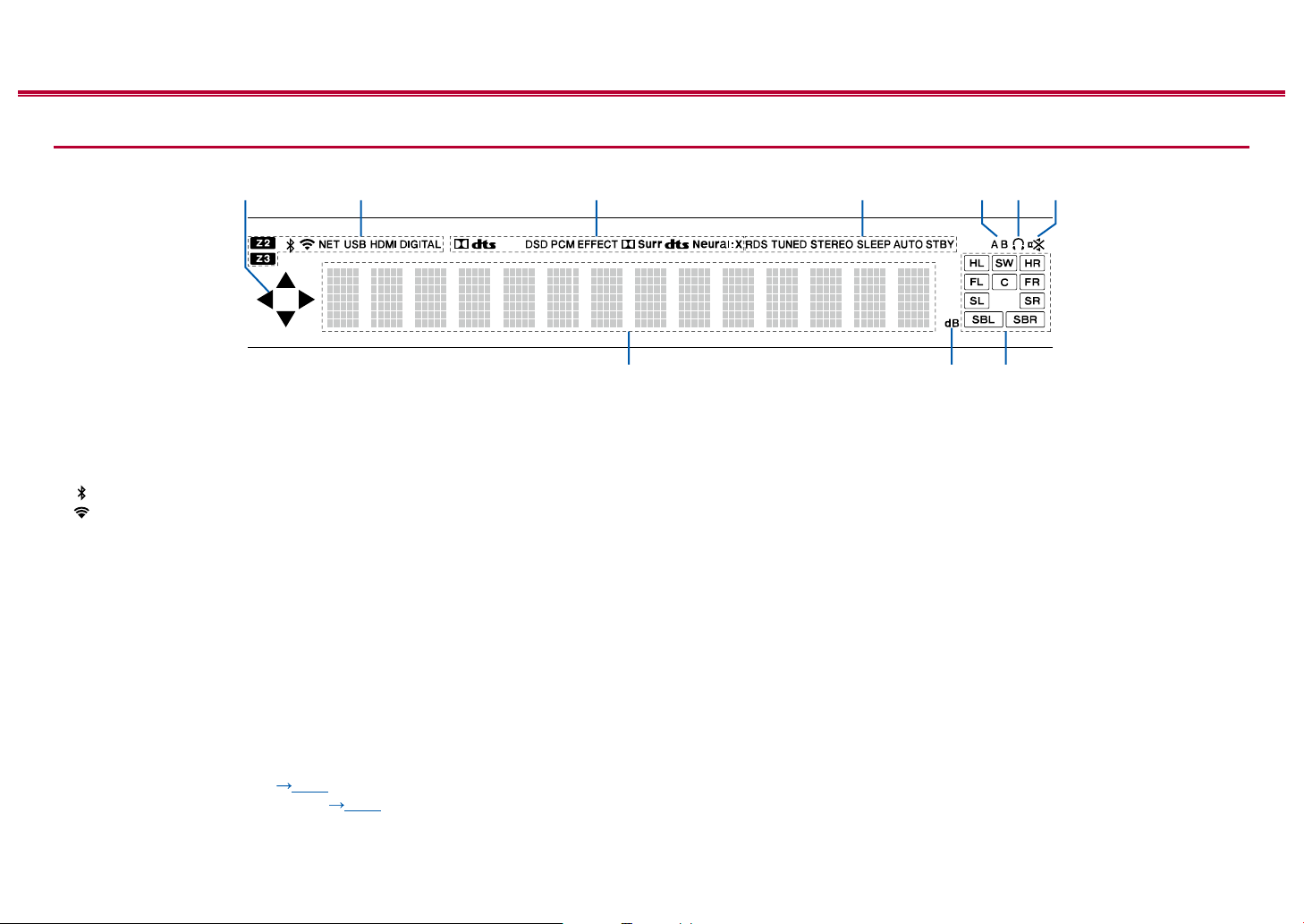
1. This may light when performing operations with the "NET", "USB" input
selector.
2. Lights in the following conditions.
Z2/Z3: ZONE 2/ZONE 3 is on.
: Connected by BLUETOOTH.
: Connected by Wi-Fi.
NET: Lights when connected to the network with the "NET" input selector. It
will blink if incorrectly connected to the network.
USB: Lights when the "USB" input selector is selected, a USB device is
connected and the USB input is selected. It will blink if the USB device is not
properly connected.
HDMI: HDMI signals are input and the HDMI input is selected.
DIGITAL: Digital signals are input and the digital input is selected.
3. Lights according to the type of input digital audio signal and the listening
mode.
4. Lights in the following conditions.
RDS (European, Australian and Asian models): Receiving RDS broadcasting.
TUNED: Receiving AM/FM radio.
STEREO: Receiving FM stereo.
SLEEP: Sleep timer is set. ( p137)
AUTO STBY: Auto Standby is set. ( p137)
5. Displays the audio output destination.
A: Outputs audio only to ZONE A.
B: Outputs audio only to ZONE B.
AB:
Outputs audio to both ZONE A and ZONE B.
6. Lights when headphones are connected.
7. Blinks when muting is on.
8. Displays various information of the input signals.
9. Lights when adjusting the volume.
10.
Speaker/Channel display: Displays the output channel that corresponds to the
selected listening mode.
12
Front Panel≫ Rear Panel≫ Remote≫
Rear Panel
Contents ≫ Connections ≫ Playback ≫ Setup
90°
180°
≫
❏ For details, see ( p14)
13
Front Panel≫ Rear Panel≫ Remote≫

Contents ≫ Connections ≫ Playback ≫ Setup
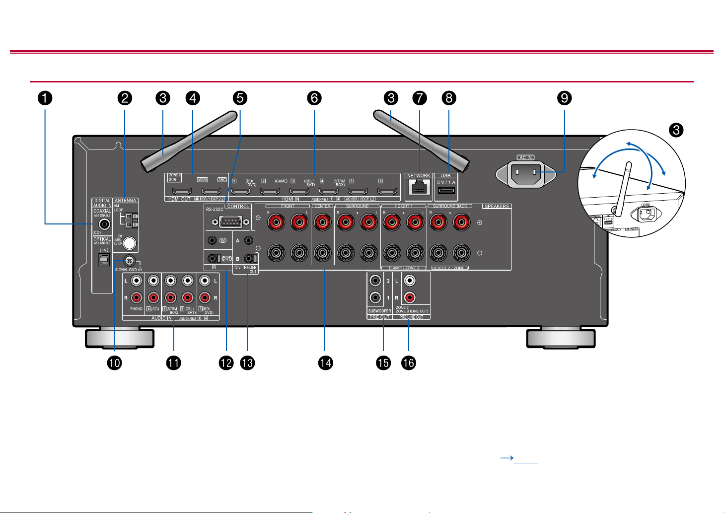
1. DIGITAL AUDIO IN OPTICAL/COAXIAL jacks: Input TV or AV component
digital audio signals with a digital optical cable or digital coaxial cable.
2. ANTENNA AM LOOP/FM UNBAL 75 Ω terminal: The supplied antennas are
connected.
3. Wireless antenna: Used for Wi-Fi connection or when using a BLUETOOTH
enabled device. Adjust their angles according to the connection status.
4. HDMI OUT jacks: Transmit video signals and audio signals with an HDMI
cable connected to a monitor such as a TV or projector.
5. RS-232C port: Connect a home control system equipped with an RS-232C
port. For adopting a home control system, contact the specialized stores.
6. HDMI IN jacks: Transmit video signals and audio signals with a HDMI cable
connected to an AV component.
7. NETWORK port: Connect to the network with a LAN cable.
8. USB port: A USB storage device is connected so that music les stored in it
can be played. ( p75) You can also supply power (5 V/1A) to USB devices
with a USB cable.
9. AC IN: The supplied power cord is connected.
10.
SIGNAL GND terminal: The ground wire of the turntable is connected.
11.
AUDIO IN jacks: Input AV component audio signal with an analog audio cable.
12.
IR IN/OUT port: Connect a remote control receiver unit. ( p62)
13.
12V TRIGGER OUT A/B jack: Connect a device equipped with a 12V trigger
input jack to enable power link operation between the device and this unit.
( p63)
14.
SPEAKERS terminals: Connect speakers with speaker cables. (North
American models support banana plugs. Use a plug 4 mm in diameter. Y plug
connection is not supported.)
15.
SUBWOOFER PRE OUT jack: Connect a powered subwoofer with a
subwoofer cable. Up to two powered subwoofers can be connected. The same
signal is output from each of the SUBWOOFER PRE OUT jacks.
16.
ZONE 2 PRE/LINE OUT jacks: Output audio signals with an analog audio
cable connected to a pre-main amplier or a power amplier in a separate
room (ZONE 2).
ZONE B LINE OUT jacks: Connect to a pre-main amplier with an analog
audio cable, and simultaneously output audio of the same source as that of
the speakers (ZONE A) connected to this unit.
≫
14
Front Panel≫ Rear Panel≫ Remote≫
Remote Controller
Contents ≫ Connections ≫ Playback ≫ Setup
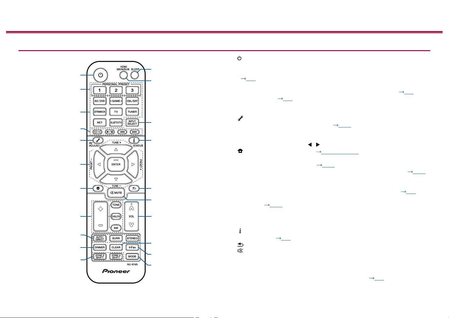
1. STANDBY/ON button
2. PERSONAL PRESET 1/2/3 buttons: Registers the current setting conditions
such as input selector, listening mode, etc. or call the registered settings.
( p98)
3. Input selector buttons: Switches the input to be played.
4. Play buttons: Used for playback operations for the Music Server ( p78)
or USB device ( p75). If the unit is switched to "CEC MODE" using
"21. MODE button" , an HDMI CEC function-enabled AV component can be
operated. (Depending on the device, operation may not be possible.)
5. (AV ADJUST) button: Settings such as "HDMI" and "Audio" can be made
quickly during play on the TV screen. ( p156)
6. Cursor buttons and ENTER button: Select the item with the cursors and press
ENTER to conrm your selection. When the folder or le lists are not shown on
one screen on the TV, press / to change the screen.
7. button: Displays the Home. ( p122, 147, 152)
8. TONE/DIALOG/SW buttons: Adjusts the sound quality of the speakers and
volume level of the subwoofer. ( p100)
9. LISTENING MODE buttons: Allows you to select the listening mode. ( p103)
10.
DIMMER button: You can switch the display o or adjust the brightness of the
display in three steps.
11.
ZONE 2/ZONE 3 SHIFT button: Controls the multi-zone function. ( p93)
12.
SLEEP button: Set the sleep timer. Select the time from "30 min", "60 min" and
"90 min". ( p102)
13.
HDMI MAIN/SUB button: Select the HDMI OUT jack to output video signals
from "MAIN", "SUB", and "MAIN+SUB".
14.
INPUT SELECT button: Switches the input to be played.
15.
(STATUS) button: Switches the information on the display and is used to
operate RDS. ( p92)
16.
button: Returns the display to the previous state.
17.
button: Temporarily mutes audio. Press again to cancel muting.
18.
Volume buttons
19.
CLEAR button: Deletes all characters you have entered when entering text on
the TV screen.
20.
+Fav button: Used to register AM/FM radio stations. ( p90)
≫
15
Front Panel≫ Rear Panel≫ Remote≫

Contents ≫ Connections ≫ Playback ≫ Setup
21.
MODE button: Switches between automatic tuning and manual tuning for
AM/FM stations ( p88). Also, when an HDMI CEC function-enabled AV
component is connected to this unit, you can switch "4. Play buttons" between
"CEC MODE" and "RCV MODE" (normal mode).
≫
16
Front Panel≫ Rear Panel≫ Remote≫
Contents ≫ Connections ≫ Playback ≫ Setup
Connections
Connecting speakers 18
Connecting the TV 51
Connecting Playback Devices 54
Connecting an AV Component in a Separate Room
(Multi-zone Connection) 57
Connecting ZONE B 59
Connecting Antennas 60
Network Connection 61
Connecting External Control Devices 62
Connecting the Power Cord 64
≫
17
Front Panel≫ Rear Panel≫ Remote≫
Contents ≫ Connections ≫ Playback ≫ Setup
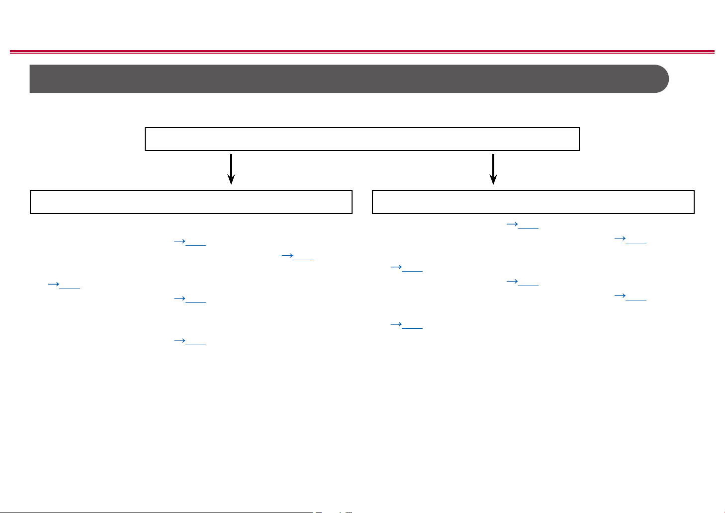
Connecting speakers
You can select the layout of speakers to be installed from various patterns when using this unit. Use the following ow chart to select the speaker layout that suits your
speakers and usage environment. You can check the connection method and default settings.
Use height speakers?
Yes No
≫
When using 1 set of Height Speakers
• 5.1.2 Channel System (
• 5.1.2 Channel System + ZONE SPEAKER ( p46)
• 5.1.2 Channel System (Bi-Amping the Speakers)
( p47)
• 7.1.2 Channel System ( p48)
When using 2 set of Height Speakers
• 5.1.4 Channel System (
p45)
p49)
• 5.1 Channel System ( p39)
• 5.1 Channel System + ZONE SPEAKER ( p40)
• 5.1 Channel System (Bi-Amping the Speakers)
( p41)
• 7.1 Channel System ( p42)
• 7.1 Channel System + ZONE SPEAKER ( p43)
• 7.1 Channel System (Bi-Amping the Speakers)
( p44)
18
Front Panel≫ Rear Panel≫ Remote≫
Speaker Installation
Contents ≫ Connections ≫ Playback ≫ Setup
≫
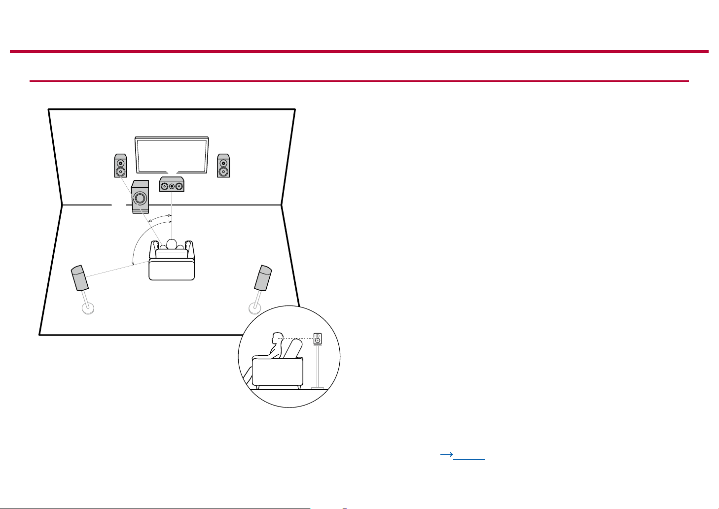
5.1 Channel System
6
a: 22° to 30°, b: 120°
a
b
3
This is a basic 5.1 Channel System. Front speakers output the front stereo
sound, and a center speaker outputs the sound of the center of the screen, such
as dialogs and vocals. Surround speakers create the back sound eld. Powered
subwoofer reproduces the bass sound, and creates the rich sound eld.
The front speakers should be positioned at ear height while the surround
speakers should be positioned just above ear height. The center speaker
should be set up facing the listening position at an angle. Placing the powered
12
subwoofer between the center speaker and the front speaker gives you a natural
sound even when playing music sources.
1,2 Front Speakers
3 Center Speaker
4,5 Surround Speakers
6 Powered Subwoofer
45
❏ Speaker Layouts and Selectable Listening
Modes ( p106)
19
Front Panel≫ Rear Panel≫ Remote≫
Contents ≫ Connections ≫ Playback ≫ Setup
54
87
≫
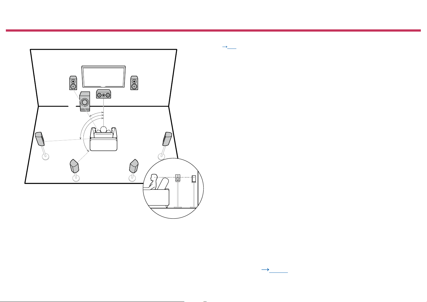
7.1 Channel System
6
a: 22° to 30°, b: 90° to 110°, c: 135° to 150°
a
b
c
3
This is a 7.1 Channel System that consists of the basic 5.1 Channel System
( p19) and added surround back speakers. Front speakers output the
front stereo sound, and a center speaker outputs the sound of the center of the
screen, such as dialogs and vocals. Surround speakers create the back sound
eld. Powered subwoofer reproduces the bass sound, and creates the rich
sound eld. Surround back speakers improves the sense of envelopment and
connectivity of sound in the back sound eld, and provides a more real sound
12
eld.
The front speakers should be positioned at ear height while the surround
speakers should be positioned just above ear height. The center speaker
should be set up facing the listening position at an angle. Placing the powered
subwoofer between the center speaker and the front speaker gives you a natural
sound even when playing music sources. The surround back speakers should be
positioned at ear height.
• If surround back speakers are installed, be sure to install surround speakers
as well.
1,2 Front Speakers
3 Center Speaker
4,5 Surround Speakers
6 Powered Subwoofer
7,8 Surround Back Speakers
❏ Speaker Layouts and Selectable Listening
Modes ( p106)
20
Front Panel≫ Rear Panel≫ Remote≫

Contents ≫ Connections ≫ Playback ≫ Setup
5.1.2 Channel System
A 5.1.2 Channel System is a speaker layout consisting of the basic 5.1 Channel System ( p19) and added height speakers. Select the height speakers that suit
your speakers and usage environment from the following three types.
❏ Front High Speakers/Rear High Speakers
Installation Example ( p22)
❏ Ceiling Speakers Installation Example
( p23)
❏ Dolby Enabled Speakers (Dolby Speakers)
Installation Example ( p24)
≫
21
Front Panel≫ Rear Panel≫ Remote≫
Contents ≫ Connections ≫ Playback ≫ Setup
≫
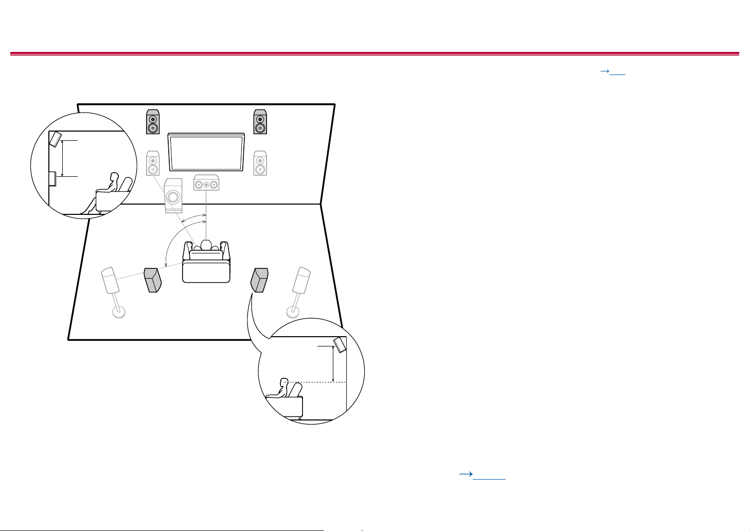
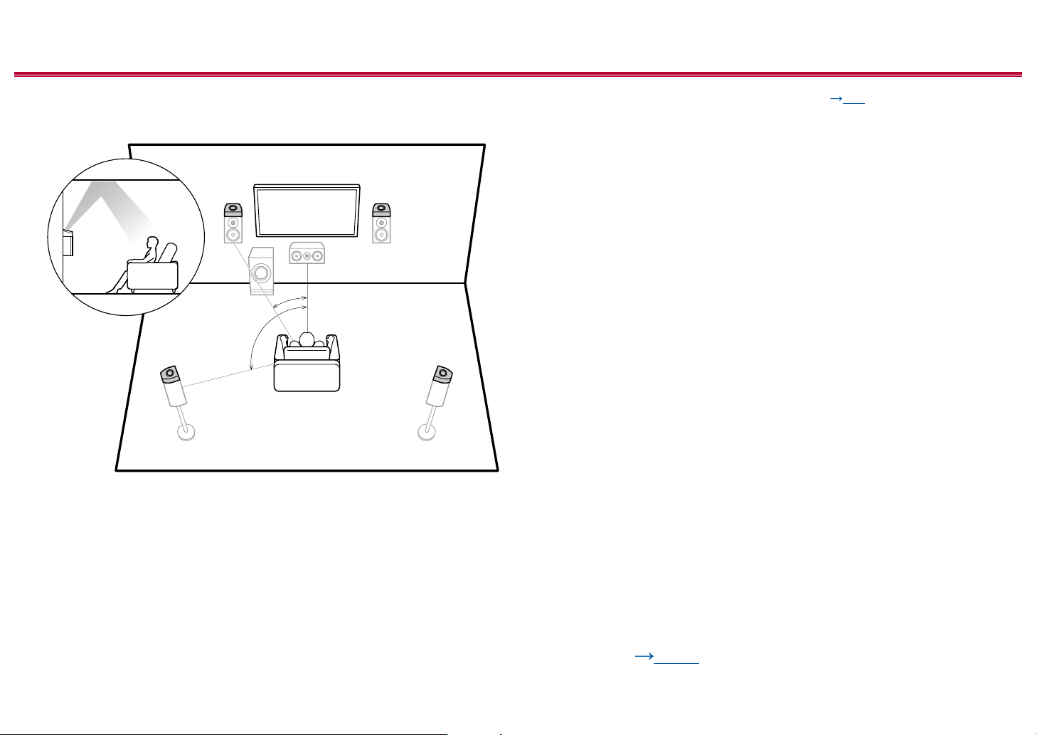
❏ Front High Speakers/Rear High Speakers
Installation Example
78
3´ (0.9 m)
or more
a
b
78
a: 22° to 30°, b: 120°
3´ (0.9 m)
or more
This is a system with the basic 5.1 channel system ( p19) consisting of
front speakers, a center speaker, surround speakers and a powered subwoofer,
and added front high speakers or rear high speakers combined. Installing the
height speakers will enrich the sound eld feeling in the upper space. Front high
speakers or rear high speakers should be installed at least 3´/0.9 m higher than
the front speakers.
Front high speakers should be installed directly above the front speakers, and the
distance between the rear high speakers should match the distance between the
front speakers. In both cases, the speakers should be set up facing the listening
position at an angle.
7,8 Height Speakers
Choose one of the following:
• Front High Speakers
• Rear High Speakers
❏ Speaker Layouts and Selectable Listening
Modes ( p106)
22
Front Panel≫ Rear Panel≫ Remote≫
Contents ≫ Connections ≫ Playback ≫ Setup
≫
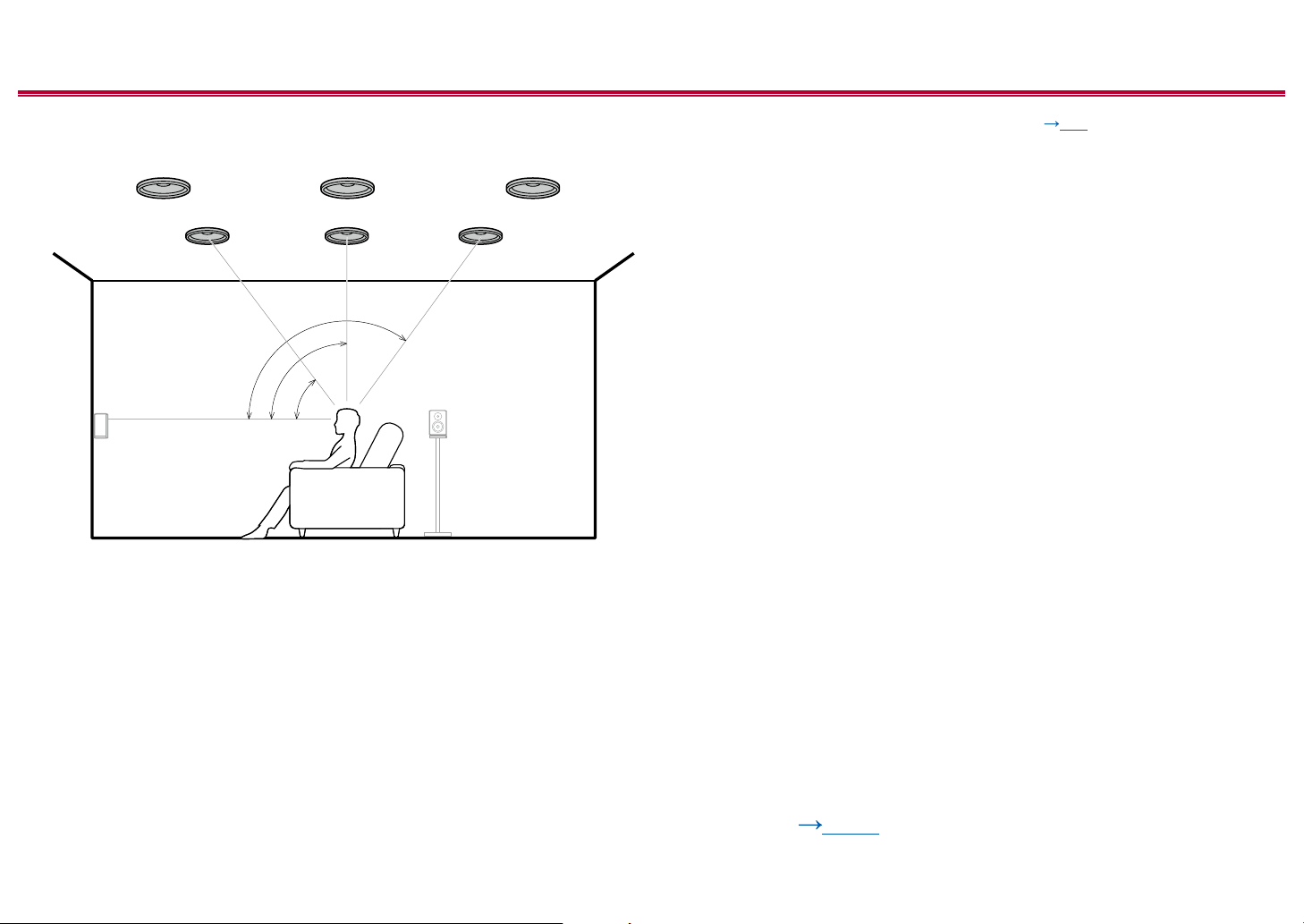
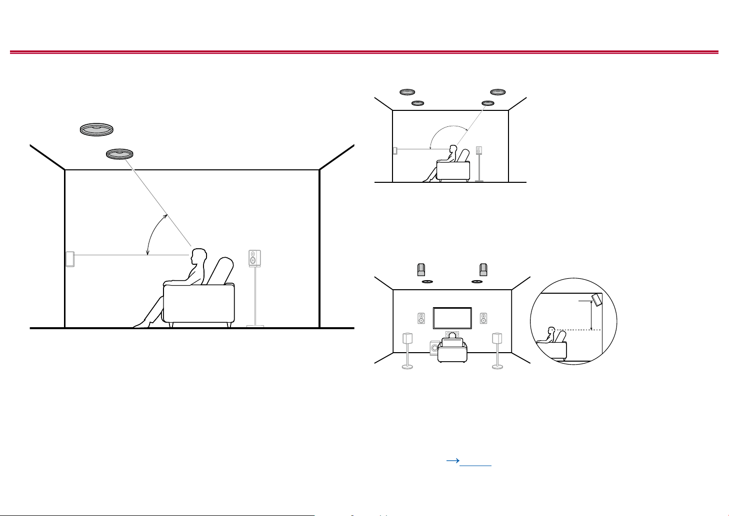
❏ Ceiling Speakers Installation Example
888
7
a: 30° to 55°, b: 65° to 100°, c: 125° to 150°
77
c
b
a
This is a system with the basic 5.1 channel system ( p19) consisting of front
speakers, a center speaker, surround speakers and a powered subwoofer, and
added top front speakers or top middle speakers or top rear speakers combined.
Installing the height speakers will enrich the sound eld feeling in the upper
space. Install the top front speakers on the ceiling anterior to the seating position,
top middle speakers on the ceiling directly above the seating position, and top
rear speakers on the ceiling posterior to the seating position. The distance
between each pair should match the distance between the front speakers.
• Dolby Laboratories recommends the setups of these types of height speakers
to obtain the best Dolby Atmos eect.
7,8 Height Speakers
Choose one of the following:
• Top Front Speakers
• Top Middle Speakers
• Top Rear Speakers
❏ Speaker Layouts and Selectable Listening
Modes ( p106)
23
Front Panel≫ Rear Panel≫ Remote≫
Contents ≫ Connections ≫ Playback ≫ Setup
≫
❏ Dolby Enabled Speakers (Dolby Speakers)
Installation Example
78
a
b
78
a: 22° to 30°, b: 120°
This is a system with the basic 5.1 channel system ( p19) consisting of front
speakers, a center speaker, surround speakers and a powered subwoofer, and
added Dolby enabled speakers (front) or Dolby enabled speakers (surround)
combined. Dolby enabled speakers are special speakers designed to face the
ceiling, so that the sound is heard from overhead by bouncing the sound o the
ceiling. Installing the height speakers will enrich the sound eld feeling in the
upper space.
Install them either on the front speakers or on the surround speakers.
7,8 Height Speakers
Choose one of the following:
• Dolby Enabled Speakers (Front)
• Dolby Enabled Speakers (Surround)
❏ Speaker Layouts and Selectable Listening
Modes ( p106)
24
Front Panel≫ Rear Panel≫ Remote≫

Contents ≫ Connections ≫ Playback ≫ Setup
7.1.2 Channel System
A 7.1.2 Channel System is a speaker layout consisting of the 7.1 Channel System ( p20) and added height speakers. Select the height speakers that suit your
speakers and usage environment from the following three types.
❏ Front High Speakers/Rear High Speakers
Installation Example ( p26)
❏ Ceiling Speakers Installation Example
( p27)
❏ Dolby Enabled Speakers (Dolby Speakers)
Installation Example ( p28)
≫
25
Front Panel≫ Rear Panel≫ Remote≫
Contents ≫ Connections ≫ Playback ≫ Setup
≫
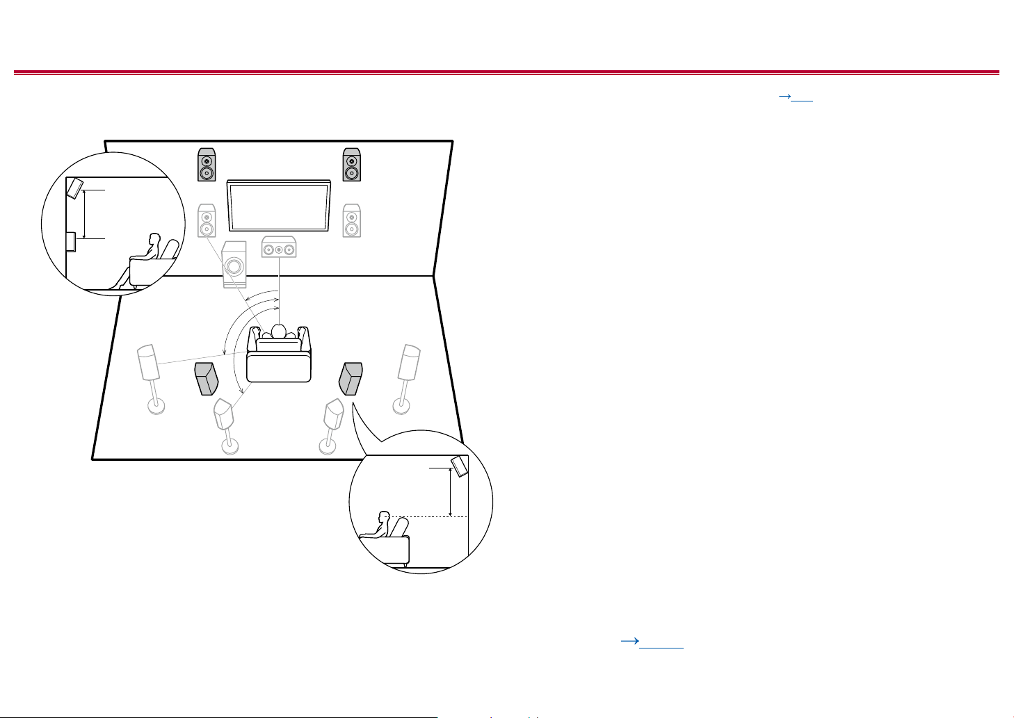
❏ Front High Speakers/Rear High Speakers
Installation Example
9bk
3´ (0.9 m)
or more
a
b
c
9bk
a: 22° to 30°, b: 90° to 110°, c: 135° to 150°
3´ (0.9 m)
or more
This is a system with the 7.1 channel system ( p20) consisting of front
speakers, a center speaker, surround speakers, surround back speakers and
a powered subwoofer, and added front high speakers or rear high speakers
combined. Installing the height speakers will enrich the sound eld feeling in the
upper space. Front high speakers or rear high speakers should be installed at
least 3´/0.9 m higher than the front speakers.
Front high speakers should be installed directly above the front speakers, and the
distance between the rear high speakers should match the distance between the
front speakers. In both cases, the speakers should be set up facing the listening
position at an angle.
9,10 Height Speakers
Choose one of the following:
• Front High Speakers
• Rear High Speakers
❏ Speaker Layouts and Selectable Listening
Modes ( p106)
26
Front Panel≫ Rear Panel≫ Remote≫
Contents ≫ Connections ≫ Playback ≫ Setup
≫
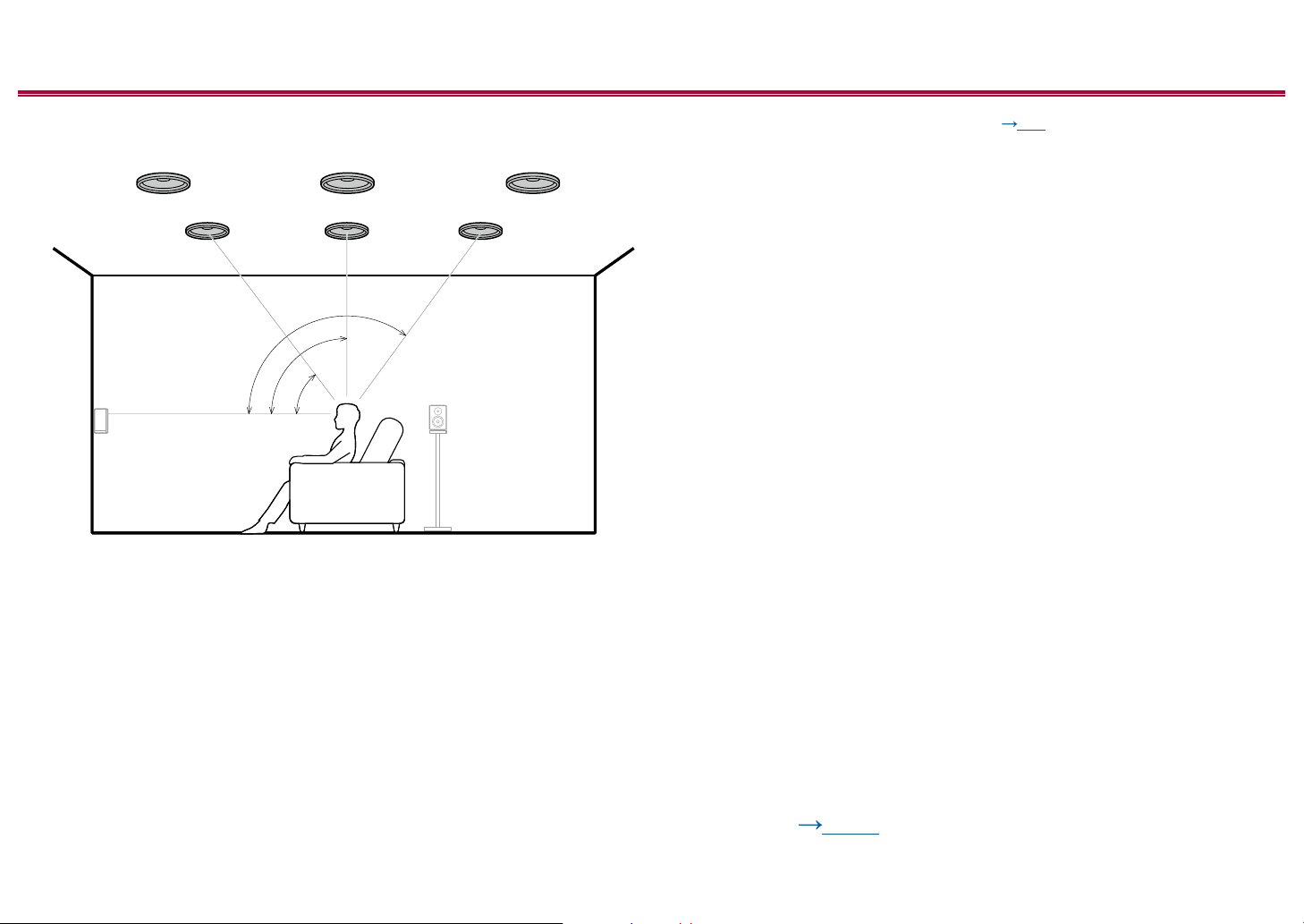
❏ Ceiling Speakers Installation Example
bk bk bk
9
a: 30° to 55°, b: 65° to 100°, c: 125° to 150°
99
c
b
a
This is a system with the 7.1 channel system ( p20) consisting of front
speakers, a center speaker, surround speakers, surround back speakers and a
powered subwoofer, and added top front speakers or top middle speakers or top
rear speakers combined. Installing the height speakers will enrich the sound eld
feeling in the upper space. Install the top front speakers on the ceiling anterior to
the seating position, top middle speakers on the ceiling directly above the seating
position, and top rear speakers on the ceiling posterior to the seating position.
The distance between each pair should match the distance between the front
speakers.
• Dolby Laboratories recommends the setups of these types of height speakers
to obtain the best Dolby Atmos eect.
9,10 Height Speakers
Choose one of the following:
• Top Front Speakers
• Top Middle Speakers
• Top Rear Speakers
❏ Speaker Layouts and Selectable Listening
Modes ( p106)
27
Front Panel≫ Rear Panel≫ Remote≫
Contents ≫ Connections ≫ Playback ≫ Setup
≫
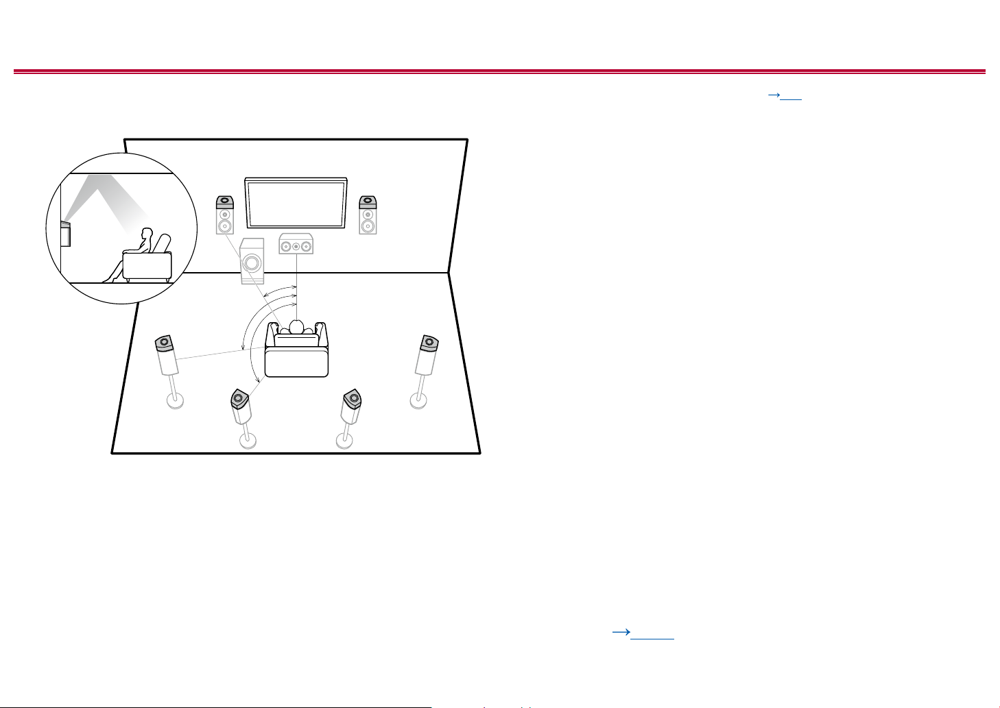
❏ Dolby Enabled Speakers (Dolby Speakers)
Installation Example
9bk
a
b
bk
c
9
9bk
a: 22° to 30°, b: 90° to 110°, c: 135° to 150°
This is a system with the 7.1 channel system ( p20) consisting of front
speakers, a center speaker, surround speakers, surround back speakers and a
powered subwoofer, and added Dolby enabled speakers (front), Dolby enabled
speakers (surround) or Dolby enabled speakers (surround back) combined.
Dolby enabled speakers are special speakers designed to face the ceiling, so
that the sound is heard from overhead by bouncing the sound o the ceiling.
Installing the height speakers will enrich the sound eld feeling in the upper
space.
Install them either on the front speakers, on the surround speakers or on the
surround back speakers.
9,10 Height Speakers
Choose one of the following:
• Dolby Enabled Speakers (Front)
• Dolby Enabled Speakers (Surround)
• Dolby Enabled Speakers (Surround Back)
❏ Speaker Layouts and Selectable Listening
Modes ( p106)
28
Front Panel≫ Rear Panel≫ Remote≫

Contents ≫ Connections ≫ Playback ≫ Setup
5.1.4 Channel System
A 5.1.4 Channel System is a speaker layout combining 2 sets of the height speakers, 1 set of left and right at the front and 1 set of left and right at the rear, to the basic
5.1 Channel System ( p19). Installing the height speakers will enrich the sound eld feeling in the upper space. Combination of 2 height speakers can be selected
from following.
❏ Combination example when Top Front
Speakers are used at the front ( p30)
❏ Combination example when Top Middle
Speakers are used at the front ( p32)
❏ Combination example when Front High
Speakers are used at the front ( p33)
❏ Combination example when Dolby Enabled
Speakers (Front) are used at the front
( p35)
≫
29
Front Panel≫ Rear Panel≫ Remote≫
Contents ≫ Connections ≫ Playback ≫ Setup
8
8
bk
bk 9
≫
❏ Combination example when Top Front
Speakers are used at the front
About the top front speakers
7
a
a: 30° to 55°
The top front speakers are installed on the ceiling at front of the listening
position, and the width between the left and right speakers is optimal to match
the one for the front speakers. When the top front speakers are used in front, the
combination of the height speakers at the rear can be selected from the following
3 examples shown at the right.
7,8 Top Front Speakers
(Example 1) Use top rear speakers at the rear
7
b: 125° to 150°
The top rear speakers are installed on the ceiling at rear of the listening position,
and the width between the left and right speakers is optimal to match the one for
the front speakers.
9,10 Top Rear Speakers
(Example 2) Use rear high speakers at the rear
9
b
78
3´ (0.9 m)
or more
The width between the rear high speakers should match the one for the front
speakers, and they should be installed minimum of 3’/0.9 m higher than the front
speakers, and tilted so they will point toward the listener.
9,10 Rear High Speakers
❏ Speaker Layouts and Selectable Listening
Modes ( p106)
30
Front Panel≫ Rear Panel≫ Remote≫
 Loading...