

Pioneer SXP-520 Service manual
(D
rrloNEerl"
The
Art
Entertainment
of
9.6uOJ
STEREO RECEIVER
SXIPE'a;O
SX-
P52O HAS
THE FOLLOWING
:
/o3.
ORDER NO.
ARP2452
Type
Ftts
HB
HEWZI
KUC
SD
YPW
AC2zOV
AC22OV-
AC22OV
AC 1 2OV only
AC1
AC24OV only
OThis manual
O For HB
For
O
OThese
manual
Ce manuel
O
O Este
and HEWZI
the
other types, refer
products
(s).
pour
manual
Power
Requirement
-23OV,
23OV, 23O-240V
-23OV,
10V,
120 - 127V,
is
applicable to SX
types, refer
are
component of
le
service comprend les
(Switchable)
24OV
23O-240V
22OV, 24OV
to the
*
(Switchable) *
(Switchable)
(Switchable)
-P5ZOIHE,
pages
to
applicable service
systems. For
explications
de servicio trata del m6todo
{,
*
Change the
HB
and HEWZI.
45-50.
manuals.
the system
de
ajuste escrito
connection of the transformer's
composition,
r6glage
en frangais.
en espaffol.
Remarks
primary
wiring.
refer to the system
CONTENTS
1. SAFETY INFORMATTON
2. SPECTF|CAT|ONS
3. EXPLODED
PARTS
4. SCHEMATIC
DIAGRAMS
5. PCB
PIONEER
PIONEERELECTRONICSSERVICElNC.
PIONEER
PIONEER
PfONEER
PIoNEER
o
VIEWS,
L|ST,..".
DIAGRAMS
PARTS L|ST
ELECTRONIC
ELECTRONICS
ELECTRONIC
ELECTBONICS AUSTRALIA
......
[EUROPEI
ELECTRONIC
."'. ... .
PACKING AND
AND
PCB CONNECTION
CORPORATION
OF CANADA, lNC.
PO. Box 1760,
N.V. Haven 1087 Keetberglaan 1,
PTY. LTD. 178-184 Boundary Road, Braeside,
CORPORATION
...............
........
............4
.....................
Allstate Parkwav Markham,
300
2
3
......
8
36
4-1,
Mesuro l-chome,
Long Beach, California90801
1gg2
6. ADJUSTMENTS
6. REGLAGE
6. AJUSTE
7.
|NFoRMAT|ON
tc
8. FOR HB
9. PANEL FAC|LITIES
Ontario
Melsele, Belgium
9120
AND HEWZI TYPES 45
Mesuro-ku, rokyo 153, Japan
U.S.A..
L3R 0P2 Canada
Victoria
3195,
,."...'
Australia TEL:
DFN
FEB. 1ee2
[03]
'..."..."....42
580-9911
pr.intecl
....,.
i'l
JapaD
40
43
51
..'.".'..'.41
....... . .
.... ....
This
meant
sary
repair
service
for
equipment
test
complex
lmproperly
of the
perform
trying
product
the
to do
manual
casual
the
is
and
products
performed
and
repair
may void
of
so and refer
intended
do-it-yourselfer.
qualified
for
Oualified
tools, and have
such
repairs
this
the repair
as
those covered
can
adversely
the
product
to
warranty. lf
properly
qualified
a
been
affect
and
service
technicians
trained
technicians;
have
properly
to
by this manual.
the
safety and reliability
you
safely,
are not
you
should not risk
service technician.
it is
not
the necesand
safely
qualified
to
WARN I
Lead in solder used
a known reproductive
(Cafifornia
When
solder, avoid unprotected
any
1. SAFETY
(FOR
USA MODEL
1.
SAFETY
The
continued
technician.
LEAKAGE
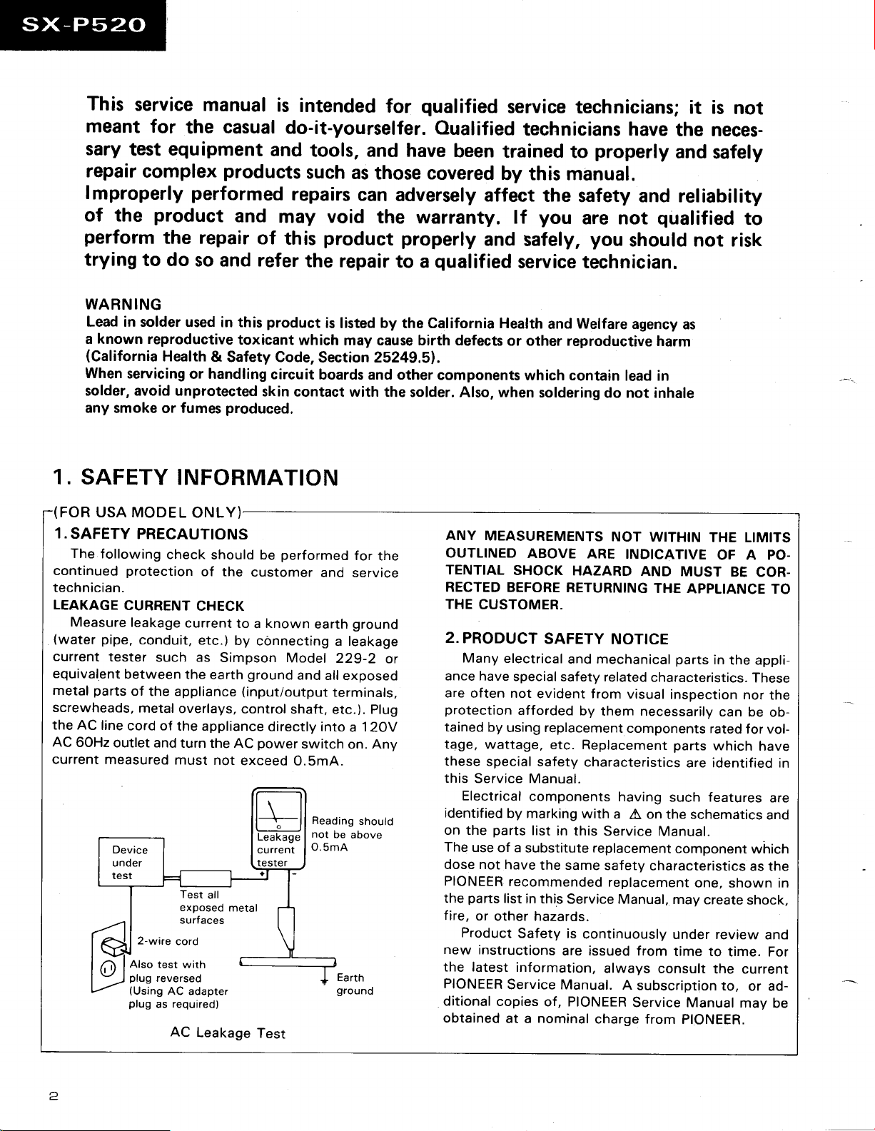
Measure
(water
current
equivalent
parts
metal
screwheads,
the AC
AC
6OHz
current
NG
Health
servicing
smoke or fumes
or handling
INFORMATION
PRECAUTIONS
following
pipe,
tester
line
outlet and
measured
check
protection
CURRENT
leakage
conduit,
between
of
metal
cord
2-wire
Also test
plug
(Using
plug
current
such as
the
the appliance
overlays,
of the appliance
turn the AC
must
Test
exposed
surfaces
cord
with
reversed
AC
adapter
required)
as
AC
in this
toxicant
&
Safety Code,
produced.
ONLY)
should be
of the
CHECK
to a known
etc.)
by
Simpson
earth
(input/output
control
not
exceed
all
metal
Leakage
product
which
circuit
skin
contact with the
performed
customer
connecting
Model
ground
and
shaft,
directly into
power
Test
switch
O.SmA.
O.5mA
is
Section 2S24g.Sl.
boards and other
and service
earth
a leakage
229-2
all
terminals,
etc.). Plug
Reading
not
be
Earth
ground
by
listed
may cause birth defects
for
ground
exposed
a 1 2OV
on.
above
the California Health
components
solder. Also, when
the
or
Any
should
or other reproductive
ANY
MEASUREMENTS
OUTLINED
TENTIAL
RECTED
THE
2.
PRODUCT
Many
ance
are
protection
tained
tage,
these
this
Electrical
identified
on the
The
dose not
PIONEER
parts
the
fire,
Product
new
the latest
PIONEER
ditional
obtained
SHOCK
BEFORE
CUSTOMER.
electrical
have
special
often not
afforded
by
using replacement
wattage,
special
Service Manual.
by marking
parts
use
of a
have
recommended
list
or
other hazards.
Safety
instructions
information,
Service Manual.
copies
at a nominal
Welfare
and
which contain
soldering
ABOVE
evident from
safety
components
list
substitute replacement
the same
in this
ARE
HAZARD
RETURNING
SAFETY
and mechanical
safety related
by
etc.
Replacement
characteristics
with
in this
Service Manual,
is
continuously
are issued from
of, PIONEER
agency
harm
lead in
do not inhale
NOT
WITHIN
INDICATIVE
AND
THE
NOTICE
characteristics.
visual
them necessarily
components
having
a
on the schematics
A
Service
safety
replacement
always
charge from
Manual.
characteristics
consult
A
subscription
Service Manual
as
THE LIMITS
OF A PO-
MUST
APPLIANCE
parts
inspection
parts
are identified
such features
component
may
under review
time to
PIONEER.
BE
COR-
in
the appli-
These
nor
can be
rated
for vol-
which
which
as the
one, shown in
create
shock,
time. For
the current
to,
or ad-
may
TO
the
ob-
have
in
are
and
and
be
2.
SPEC|F|CAT|ONS
STEREO
Amplifier
Continuous Power
Continuous Power
Music Power
Total Harmonic
(1
kHz,2O
Miscallanaous
Power Requirements
Power
Dimensions
Weight
FM/AM
FM
Frequency
Usable
Sensitivity
Signal-to-Noise
Signal-to-Noise
Distortion
Antenna
AM
Frequency
Sensitivity
Antenna
LW Tuner
Frequency
Sensitivity
Antenna
REGEIVER:
Section
Output
Output
(DlN)
..............
Distortion
W, 8 ohms)
Consumption ...............
(without
Tuner
Sensitivity
(MW)
Turier
Section
Range
(DlN)
Input
Tuner
Range
(lHF,
Section
Range
(lHF,
packagel
Section
............................87.S
......................,..........
..................
Ratio
Ratio
..............
Section
................................
Loop
............
Loop
SX-PS2O
(DlN)
......................30
(1
kHz,
(RMS)
(1
....................22O
.260
.........
Mono
Stereo
(lHF,
85
dBf Input)
(DlN)
.........,...........Stereo:
anrenna)
(For
LW
antenna)
T.H.D.
....,...............35
(1
kHz,
T.H.D.
kHz, T.H.D.
-
230 V AC,
(W)
x 180
MHz
Mono:
S/N 26
S/N 46
aquipped
dB: 1
dB:
..........
........
.75
ohms
531 kHz
153 kHz
............
W +
57o,
8 ohms)
W +
57o,
.....48
(H)
(1
8 ohms)
W + 48
107o,
8
.O.2To*
50/60 Hz
............. 182 W
(D)
x 301
............4.9 kg
to 108.0
1
2.8
dBf. IHF
pV/75
.2
50
models
ohms)
pV/75
pV/7S
Mono:
Stereo: 73
Mono:
Stereo:
(1
0.S 9o
unbalanced
to 1.602
.......350
Loop
Antenna
only)
to 281
.....
1S00
Loop
Anrenna
30 W
W
35
W
ohms)
mm
MHz
ohms
ohms
77
dB
dB
66 dB
60 dB
kHz)
kHz
pV/m
kHz
pV/m
Accessories
Remote
Dry
FM
AM
Operating
*
NOTE:
Specifications
without
Control
Cell Batteries
T-type
Antenna
Loop
Antenna
Instructions
Measured
notice
Unit ................
(AAA/RO3-UM4)
by audio
spectrum
and
design subject
improvements.
due to
......................
analyzer.
to
....................1
................
...............1
.................1
possible
modification
2
...........1
J
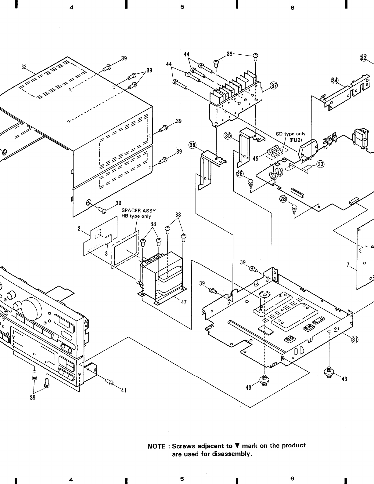
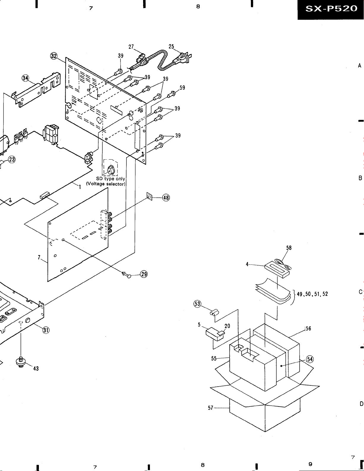
3. EXPLODED
NOTES:
o
parts
The
o
The
be
o
Parts
Parts
Mark
o
o
o
o
o
Ol
A
with
an encircled
mark
A,
sure to use
list
No.
7
8
9
10
ll
12
13
L4
IE
16
17
18
19
20
2L
22
ZJ
24
25
found
parts
" A "
marked
by
of Exterior
Description
1
POWERASSEMBLY
2
TRANS
3
INSULATOR
4
LOOP
5 REMOTE
6
ANTENNA
-
(CU
SXO4O)
FRONTASSEMBLY
TUNER
VOLUME
HEADPHONE
VOLUME
ROTARY
BAND
FUNCTION
SFC
BUTTON
WAI{E
TIMER
POWER
AUDITION
BATTERY
TUNER
REMOCON
FUSE
CARD
SCREW
AC POWER
BUTTON
VIEWS,
on some component
of identical
are
not always
and
ASSEMBLY
CONTROL
ASSEMBLY
ASSEMBLY
ASSEMBLY
KNOB
I{NOB
BUTTON
UP
BUTTON
BUTTON
BUTTON
BU'ITON
COVER
DISPLAY
FILTER
(STEEL)
CORI)
number are
designation.
kept in
Packing
(L)
UNIT
PANEL
PACKING
generally
parts
unavailable because
indicates
stock. Their delivery
Parts No,
AWZ3944
AWZ3930
AEZTOO4
ATBlOO6
AXDt267
AWZ3950
AW23938
AWZ394r
AW23942
AAB125O
AABI273
AAD2177
AAD2208
AAD2I79
AAD2180
AAD21B1
AAD2183
AAD21B5
AZAI375
AAK2260
AAK226I
AAX-243
ABA1O95
ADG1049
the importance
AND PARTS
they are
time may be longer
Mark No.
A
A
A
not in our Master
of the safety
4I SCREW
42
43
44 SCREW
45 FUSE
46
47
48
49
50
51
E9
54
55
56
58
LIST
factor
than usuol
Description
NUT
(RUBBER)
FOOT
(T800mA,
(i)
FFC
POWER
SPACER
OPE. INSTRUCTIONS
(Dutch,
Portuguese)
OPE.
INSTRUCTIONS
(Dutch,
Portuguese)
OPE.
INSTRUCTIONS
(English,
Italian)
RECEIVER
OPE. INSTRUCTIONS
(English,
Italian) CASSETTB,
DRY CELL
SHEET
FRONT PAD
REAR
PAD
PACI(ING
FM ANTENNA
SCREW
Spare Parts
part.
of the
or they
TRANSFORMER
Su'edish,
RECEMR
Swedish,
CASSBTTE,
French,
Freuch,
(R03,
CASE
Therefore, when
may be unavailable.
FUl)
Spanish,
Spanish,
Germant,
Germaru,
CD
"AAA")
List.
replacing,
Parts No.
cB230P080FMC
NI{9OFUC
REC-434
VBZ3OPl6OFMC
AEI{-507
ADDllOO
ATS1394
AEC1236
ARC1324
ARC1337
CD
AREI223
ARE1233
AEX-021
AHGlO4O
AHA1476
AHAI477
AHD22T9
ADHlOOS
VBZ35POSOFMC
26
RUBBER
27
2B
29
30
31
32
33
34
35
36
JI
38
39
40
STRAIN
NYLON
SPACER
FRONT
CHASSIS
REAR
BONNET
PACI(
HEAT
HEAT
HEAT
SCREW
SCREW
SCREW
A
SHEET
RELIBF
RIVET
PANEL
PANEL
HOLDER
SINI{
HOLDER
SINI{ I{OLDER
SINK
AEB1111
AEC_882
AEC1160
AEC135B
AMB1937
ANA1136
ANC1829
ANB1326
A
B
ANG1434
ANG1628
ANG1629
ANH1361
BBZ3OPO60FMC
BBZ3OPOSOFZK
BPZ26POSOFMC
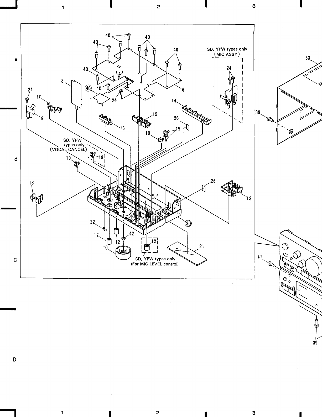
SD, YPW
types
only
cANcEL)l
2
typos
YPW
SD,
(urc
essy)
3
only
l-----t
Zo"
f\
\
t8
\
ffi
2
F,N
l-j
5
"=----€
\
2"'
1o'o
6
{'\
w,
$
\r
\\-
i\
I
I
\
4{N
mark
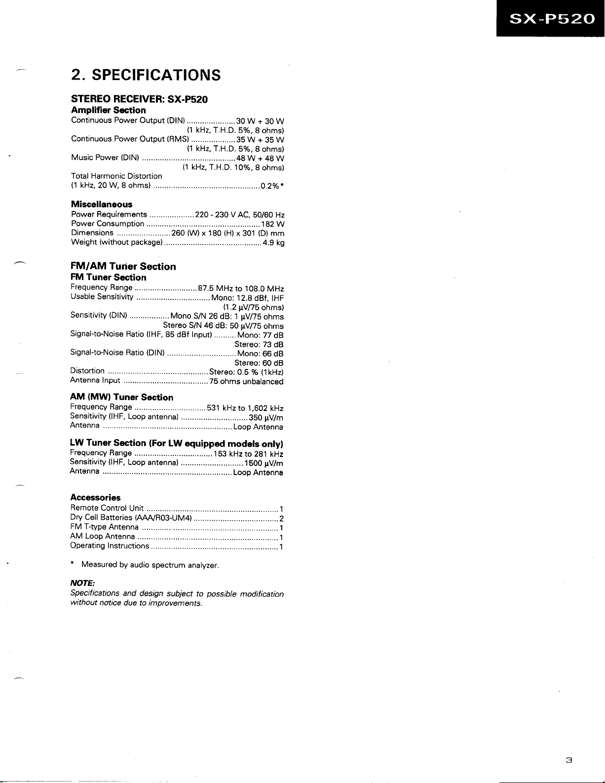
NOTE
: Screws
used
are
adiacent
for
to
V
disassemblY.
I
-l
6'
on
the
product
a
\-@
49.50,5r.52
D
I
8
I
I
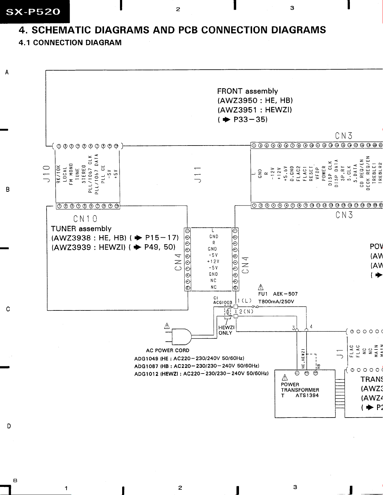
4.
SCHEMATIC
DIAGRAMS AND
PCB CONNECTION
DIAGRAMS
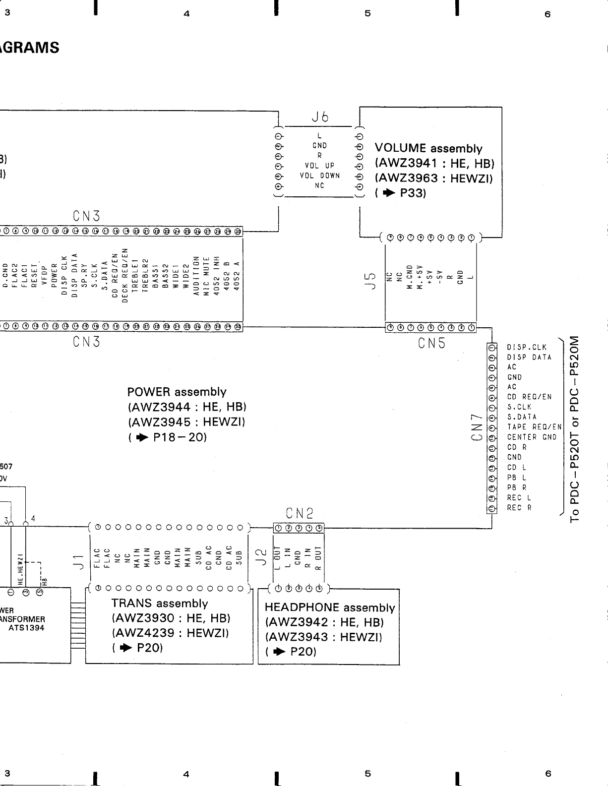
4.1
CONNECTION
TUNER assembly
(AW23938
(AW23939:HEWZI)
DIAGRAM
CNlO
HE, HB)
:
(
P15-17)
+
(t}
P49,50)
=-
z-
a)
FRONT
(AWZ395O
(AW23951
(
>
assembly
: HE,
HEWZI)
:
P33-35)
HB)
CN3
v<zu
'o<<o-=
'l-la
a
-)
lo @
'-+OLrGqqo,:ydd
o oo o o oo@
.)rd
=o:aa -d
:-
o @ @ @ @@ @@
o:uc66
z
-'coF-
o
@@@
rr
CN3
POV
(A\
(A\
(+
AC POWER CORD
(HE
ADGlO49
ADG1o87
ADG 1 Ol 2 IHEWZI
AC220-23ol24OV
:
r AC22O-23O123o-24OV
tHB
AC22o-
t
2
5o/6OHzl
23ol23o-
t2(N)
Hzl
5Ol
5O/6OHz)
'0V
24OV
50/60Hzl
I
4
3
-i
-
I
lo
(6)
F) /6)
A
POWER
TRANSFORMER
T ATSI394
-rooooo
I
-
l-
- l<<OolJJzz<
---")
lu
-I
[
'l-tr'
(AWZ:
(AWZz
(>
I
z
=
A t\l
P:
3
\GRAMS
l)
t)
4
5
Jb
L
CND
e'
VOL
Vt)L
UP
DOWN
NC
VOLUME
(AW23941
tJ
(AW23963
(
P33)
>
assembly
:
HE,
HB)
: HEWZI)
oN_F^
zooul-"oGJ]oo<<o
j
i; H = = ? 7Z;:.
v<zg
=i=>v{t5;}_-_*=31-=
j=^
.ooou<=s
.-:u--Aqqo
l-
oo@o
CN3
507
@@@o@@a]
z
q
t
p
=
"roo-J
o@@@@@
ou--=-
u;5
--=
= =;
- -
-
Ntu
- fi
3 3
-ovs
POWER assembly
(AW23944
(AW23945
(
P18-20)
+
: HE,
: HEWZI)
ooooooooooooooo
HB)
a\ [tr)
ut\c
I
|
(
a re., rn ri\ ril rn rn ri\ ri)
\YYYYYYYYY
o>
._..2@>>a
==a+n@Ez)
a
-l
.r+tO
==
CN5
r-z.
a)
DISP.CLK
D I SP DATA
AC
GND
AC
CD REO/EN
q
(
nt
S.DATA
TAPE
REO/EN
CENTER GNO
CD R
CND
CD L
PB
L
PB R
REC L
R
REC
o
N
ro
o-
O
o
L
L
o
F
o
N
LO
o-
O
o
ot-
I
I
cl6)
flER
\NSFORMER
ATS I 394
I
- l:?--=-a====
-
--)lu*
)>Zooai=o=^=^=
l-l
-l
==--==--;-;-'
ooooooooooooooo
TRANS assembly
(AWZ393O
|AWZ4239
(
> P20)
=?=?e
:
HE, HB)
: HEWZI)
I
At l-z^z-
\v
lJ -
_lozo
)
| ,a n
t-
I
I
Jnd,anlnln
HEADPHONE
(AW23942
(AW23943
(
P20)
>
assembly
:
HE, HB)
:
HEWZI)
5
I _t
6
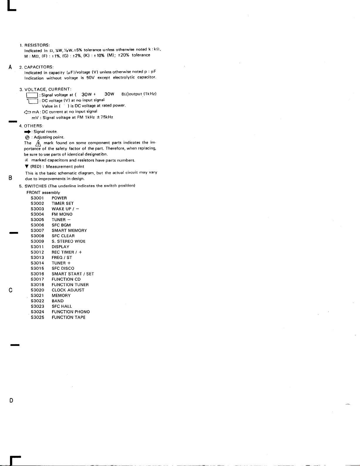
RESISTORS:
1.
ndicated
f
M:Mo.
2. CAPACIToRS:
A
Indicated in
Indication without
VOLTAGE, CURRENT:
3.
l-*-l:Signal
[
mA: DC current
4-
-
B
_
C
mV
4,
OTHERS:
Signal
{:
: Adiusting
@
ffre
I
portance
sure
be
marked
X
(RED)
V
This is
due lo
5. SWITCHES
FRONT
S3OOl POWER
S3OO2 TIMER
S3OO3 WAKE UP /
S3OO4 FM MONO
S3OO5
53006 SFC BGM
s3oo7 SMART
S3OO8 SFC CLEAR
S3OO9 S.
S3011 DISPLAY
53012
S3OI3 FREO / ST
S3OI4 TUNER +
s3015 sFc Dtsco
S3016 SMART START / SET
S3017 FUNCTION
S3OI8 FUNCTION TUNER
s3o2o clocK ADJUST
S3O21
S3O22 BAND
S3023 SFC HALL
53024 FUNCTION PHONO
S3025
t/ew,!'Yo
(),
in
%W,
(Fl:t1/o,
: DC voltage
Value
: Signal
mark
of the safety
use
to
:
the basic
improvements
assembly
lGl:t2%,
capacity
voltage
voltage at ( 3OW
(V)
(
in
at
voltage
route.
point.
found
parts
of
capacitors
Measurement
schematic
underline
{The
SET
TUNER
STEREO
TIMER / +
REC
MEMORY
FUNCTION
tolerance
(K)
(uFl/voltage
is
inPut signal
no
at
voltage
is DC
)
inPut
no
FM lkHz
at
on some component
factor of the
identical designatibn.
resistors
and
point
diagram,
in
design.
indicates the
-
_
MEMORY
WIDE
CD
TAPE
unless
:t10%
(V)
unlessotherwise
except
5OV
+
3OW 8(l)output.(1kHzl
rated
at
signal
t75kHz
part.
Therelore,
parts
have
the actual
but
switch
othemis€
(M);
t20%
electrolytic
power'
parts
numbers.
position}
k
noted
tolerance
p :
noted
capacitor'
indicates the
when replacing,
vary
may
circuit
:k(t,
pF
im-
D
l-
J
.0S
epsq ol rslsr
l\W3H roi ms
.eqyt
I
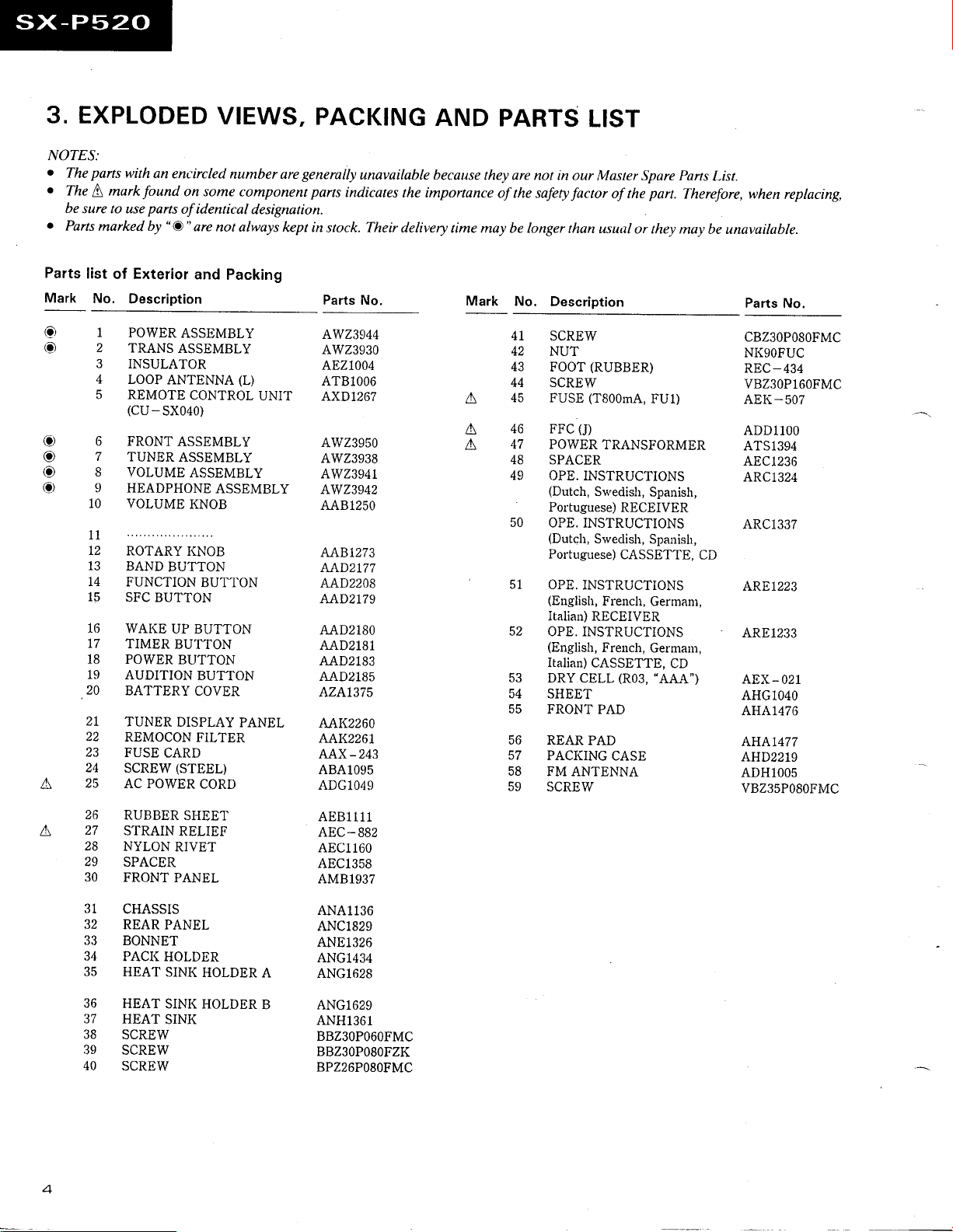
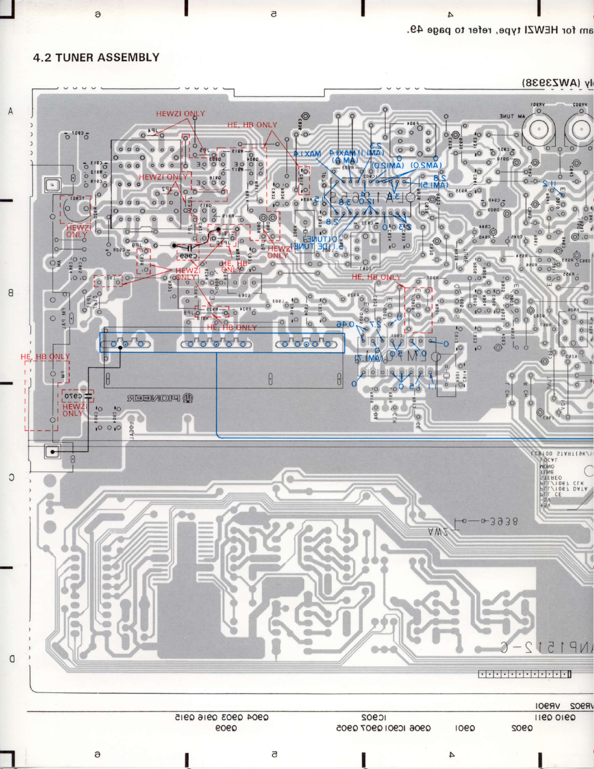
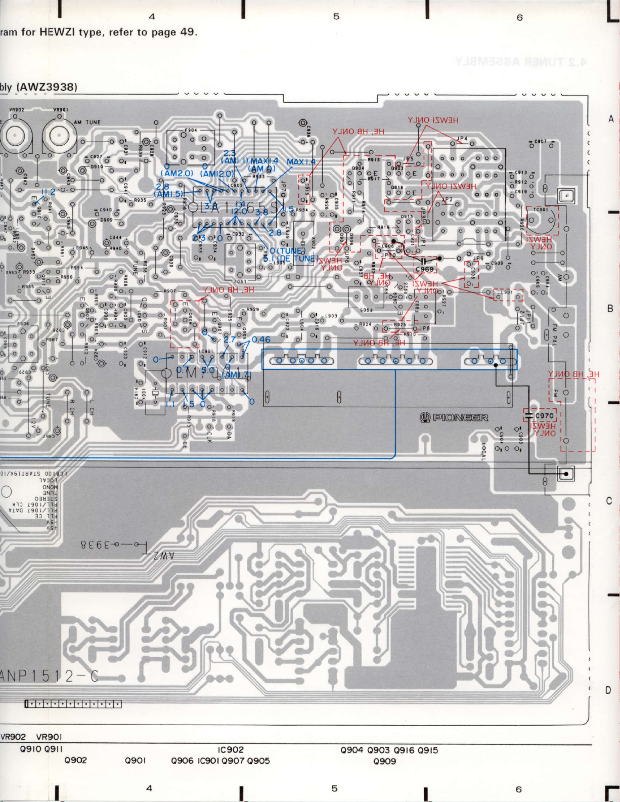
4,2 TUNER
oo
ilr:,lil
hHLX.*
l.-
o;
ASSEMBLY
HEWZI
!#Ft't*Jl$kffi
"
^ :
i"i i?.1 ,-- ,.
i*..u'lo
Su++'"ft{-ili1tffiH'
W
OI\LY
)'
--o=^.
}IE, II8 ONLY
\:
;"
i'..$1",.
-o
A tlx/
M
(et
\
-\
*:i1V'EIY.Io'qt
'^
o
^o
i".-.NVZ
:
i:
:
i*,
-.='
{8€€8SWA) vlr
u7"
ltlur
\ ," - \
r^) /al
NV
:''efi
*
;
e,;;;**"
I]E, HB
o
si
rJ
:i"19,,fl
tHEWlt,^ ,^ |
'
nNll \' I
o- n-
ro
resnrem@
o'o
3
|
:":-
;
nor.0
2lrBtal
br aE
P-*3438
./
-l
ere0 areo Eoeo
eoeo
I
T
loeo
soell
\oeo roeJr
eoeo
I
I
aoeo
I
I.TTTTTTTTF|T'N
roeo
qfel9.t
toeFV
I reo
so€9!
oreo
I
rle
ler
.eqyt
ISW3H
rol
msrgeib
cifemedcZ
(SeeeSWAI
yldmeeae
f, 3l/lUT
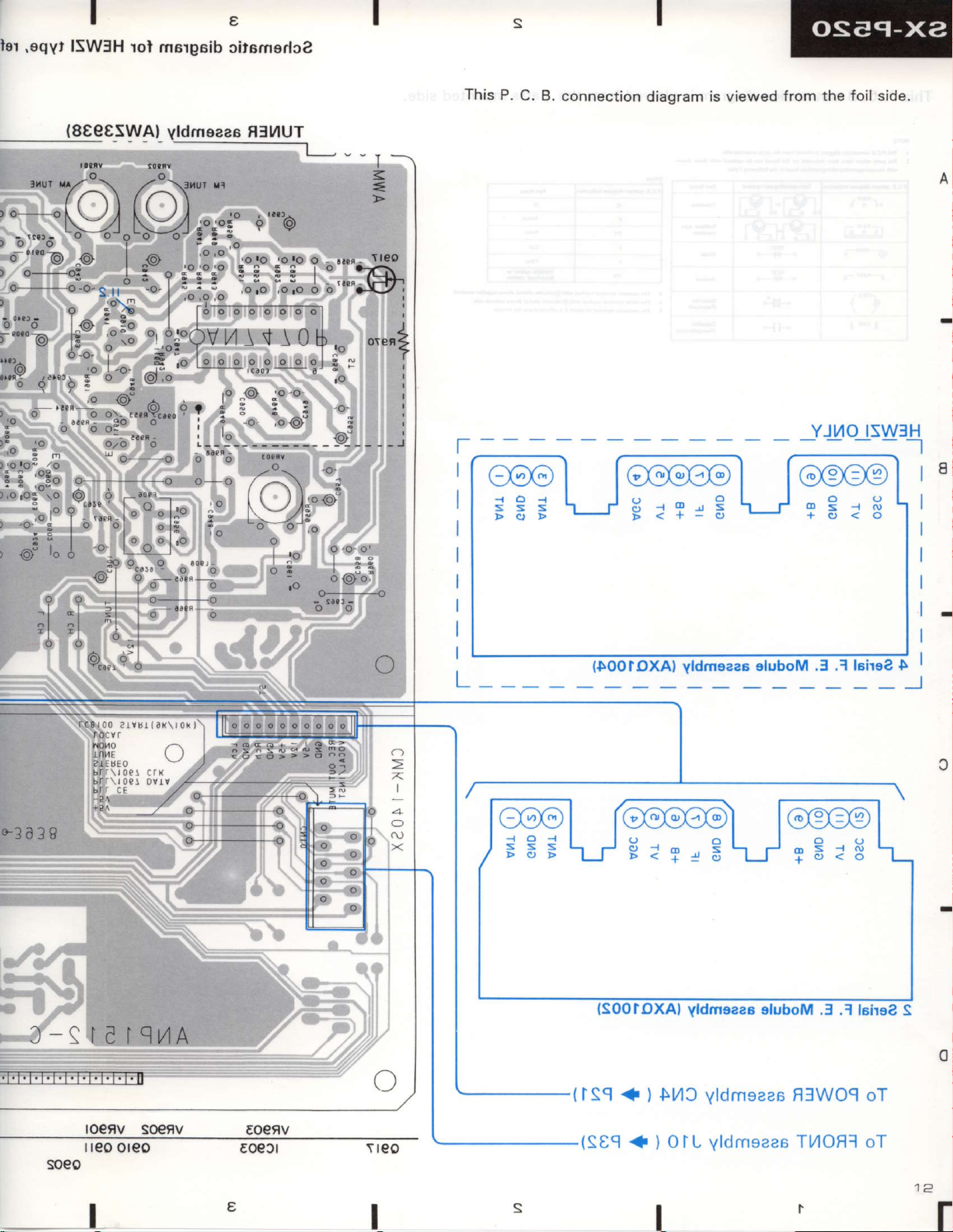
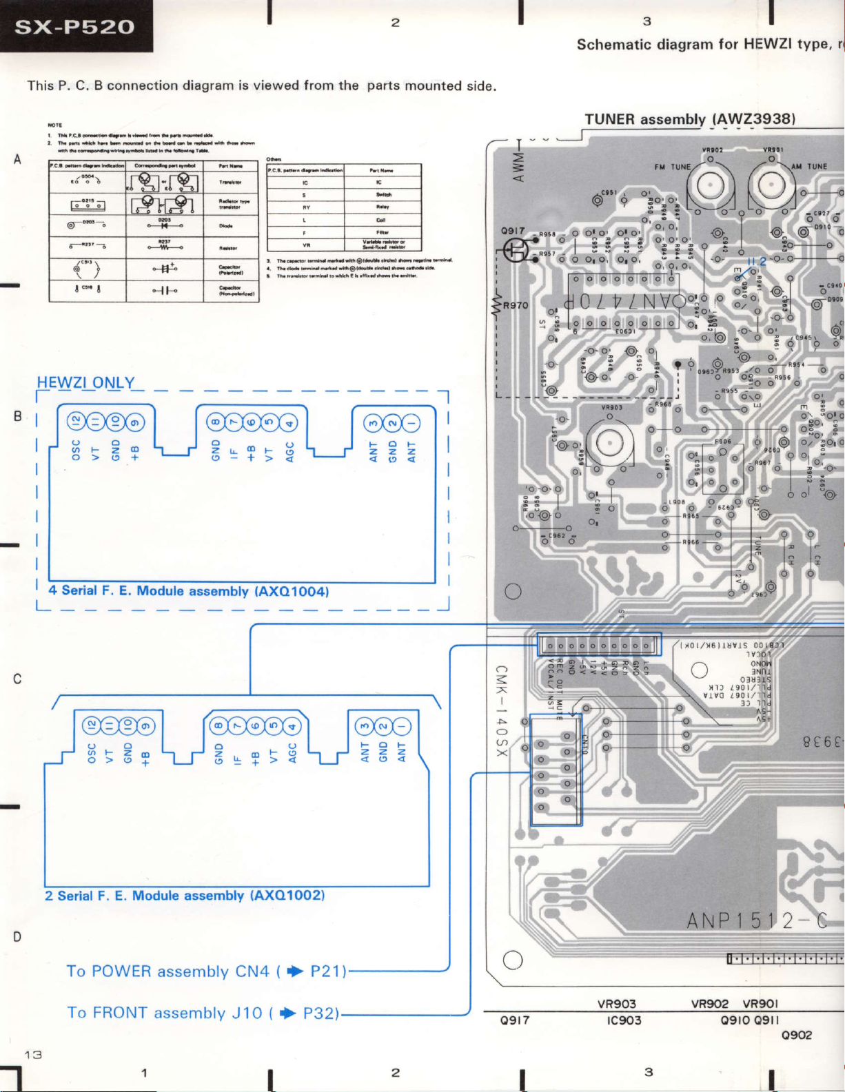
This P,
C.
B. connection
e@@l
diagram is viewsd
from the foil side.
_YJr/O_1SW3H
loo@ool l@@o@
S3;\-/E:r:3\-/r3:8
ml
@el ro@@o@l l@eo@
SS;\-lJE=r-,S\JrE:3
{SOOIOXAI
(rsq
+)
yldmsaae
$11c
oluboM .f .1
yldmsaas
H]WOq
lcirae S
oT
0
roetv
I
teo oreo
s@fv
T
reo
I
(seq
{
)OTL
yld
I
msaas
TMOF]
oT
"l
Schematic diagram
{or HEWZI type,
rr
This P. C. B connection
rgr'rgr
r9rOr
da'
)
"iF
HE
WZI ONLY
T
B
I
lr
I
I
diagram
viewed from the
is
! fr.'Fdndnilr'fror-
parts
mounted
side.
TUNER assembly
(AWZ3938)
"'"-rA\
=
6'"'+
osrz
-
s!.
o o1o,_ oto:
_-
"i"i
@"",':
!
; tooooooo,il I
; tooooooo,il I
' I | | ^i:./4.|
> lr n /
lReTo
:
,o
Fi
oo9lo
I
o
lo
I | | -5 . ^ |
h A t +, i Ht VA"to ,o l-o
",
o:f
o:Ytt
j
: i: I
,o
s:
{o} o'
o o
o o
o o o o o o
o o o o o o o
3lo
'6 -
or
oo {O
.:::|
i^^i
L.t
^
;r
/-r----,,\
t.![,U
o'r)-or
-.
I
1" ;"'"o
ol
"!";"iNV'\Y/;_
.
-
o,
:':' ^
"i":';":"*
o o o o o ol
.L
"8.,
o ",r._p.J
oY,o.t _..^
/ N | \J /-,o,
y1t\v!:o,
"''nuY!o:
olo.
o
l o.
- - '
106r
o, !.
?
:
"i
.t
J
i'*'9-'X;3:*-;':'
;
I
oo'u'o o-
"-" o.--
"
o!
o'!" o?
_.,."_
' 'l',1-rJtJt
"
'@^
":
i
|
o
,o
3
3
'
-L^
_L^
o(9: o
^ {Ol
s-.8"',';.
O O\O
- -o
., l^;i']
;
;l
e.,",o
a I L l" l_
/-A\'*'
"
?
@. O
|
l,
r-.*-'
d^-,
d^-z
6^
3 S
"jl
v!
;i.
"'"
9 ^_A
I
|'oo
.O-
.O-
O'
O'
o,
l*^'1'
-
v,,,.@o')'gol"
"l;""0I
.o
F^
l.e}
s
,6
(9
^aI
-
i
O'""b i"'
-.
-'
;
o "31'
c'...
.i
l
vv
""
8",:
%
b
"
o.o,
(O)
(O)
"
"
p
\\r/
I
Serial
F.
E. Module
2 serial F. E. Module assembly
To
POWER asse nr b ly cN4
assembly
1
(
0O4,
.}
P21)
{AXO
{AXO1O02)
3
(-J]]
Ct:tgig!
O
Ae+
8€6t-
ANP I 512-
T;FFFT;TTTTT;T;
lFT.
C
rqoNT.r:.:-r,rl,ly
T,,
Jlrt +P32\
09r7
I
VR9O2 VR9OI
09rl
09ro
I
I
a4
ram for HEWZI type, re{er
(AWZ3938)
bly
to
page
49.
"oi
fO fO:"*'
\-4
vj
?
..*
j"::
":';t
:,
"'#'m,
g;
"
-i
",.%,l
,-8-:,"i,
"" :y
.ffint,
Ii+;
-
:l
j',,""rJ'r'
#c.:
j
{.,,,,b
:;:.
i}'i.i
i' i= T, t i LJtffi
9:r: .
-.
"i",:il,i
.
i:;,1":1t
*"i
.;.:
-
f
:'$fih-#{
'
'f5*'"
"
[,q,_-1i I i I
h;A
H,.[
ffi#,
i-i'
lffiff"1'#''ad"
!,
3,,
^ Xo'"
/;
l/L",*l-*#jlqi,
ii--
l*",'
[u[
ooo
o o o
t5w
ui:i4il'
"$lh
i"t,
*-*,#1"
oo
:,"*:*'l
i'i'iE3.u:.r=l*i;i$;
i3,
*-
o-;''o'"'iin
u
*ii:,;A""*r'
",i
'
":
-""*{"
i,,,
oo--;o
ls
ffi':tffi#<t,,.r
:i'.".',L_-,
s
":;##''
I
.T:":jii*,.In
I
I
i
.,,
11
ooo
l
ooo
]":_
;Fi[.fia
jffij
l=jl
"1.:'i
_Fi dl
-sfl
i1i
I
,
0 /16lr3vts 00
\
\NP I 51 2 C
vR902
09ro 09r
t 0l1
t nr
^q+
VR90l
I
o902
I
€ 6 t€-ol
o90l
'Z,T\V
0906
rc90l
tc902
0907 0905
0904 0903
09t6 09t5
4
2
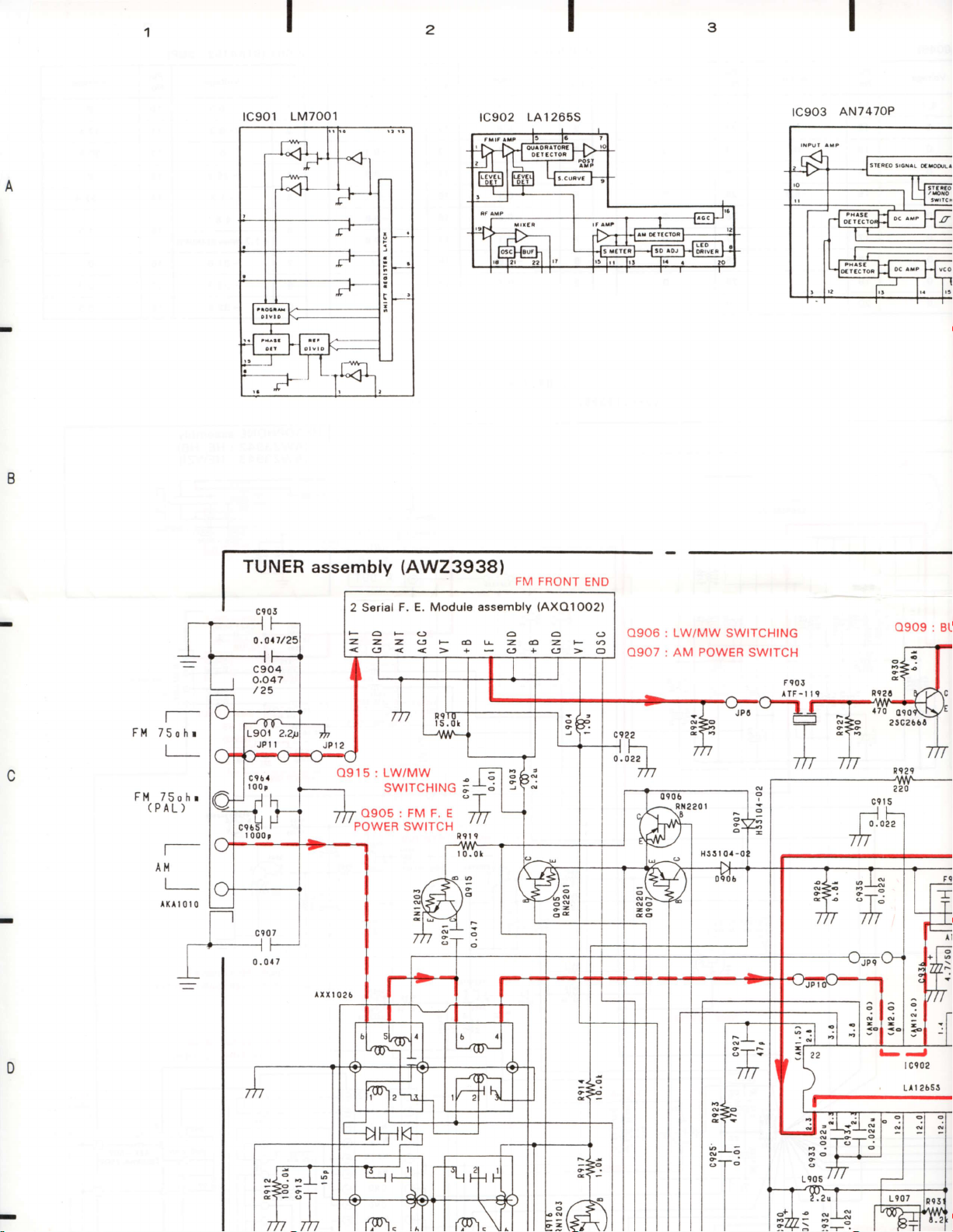
tc901
1M7001
rc902
I
LA12655
rc903
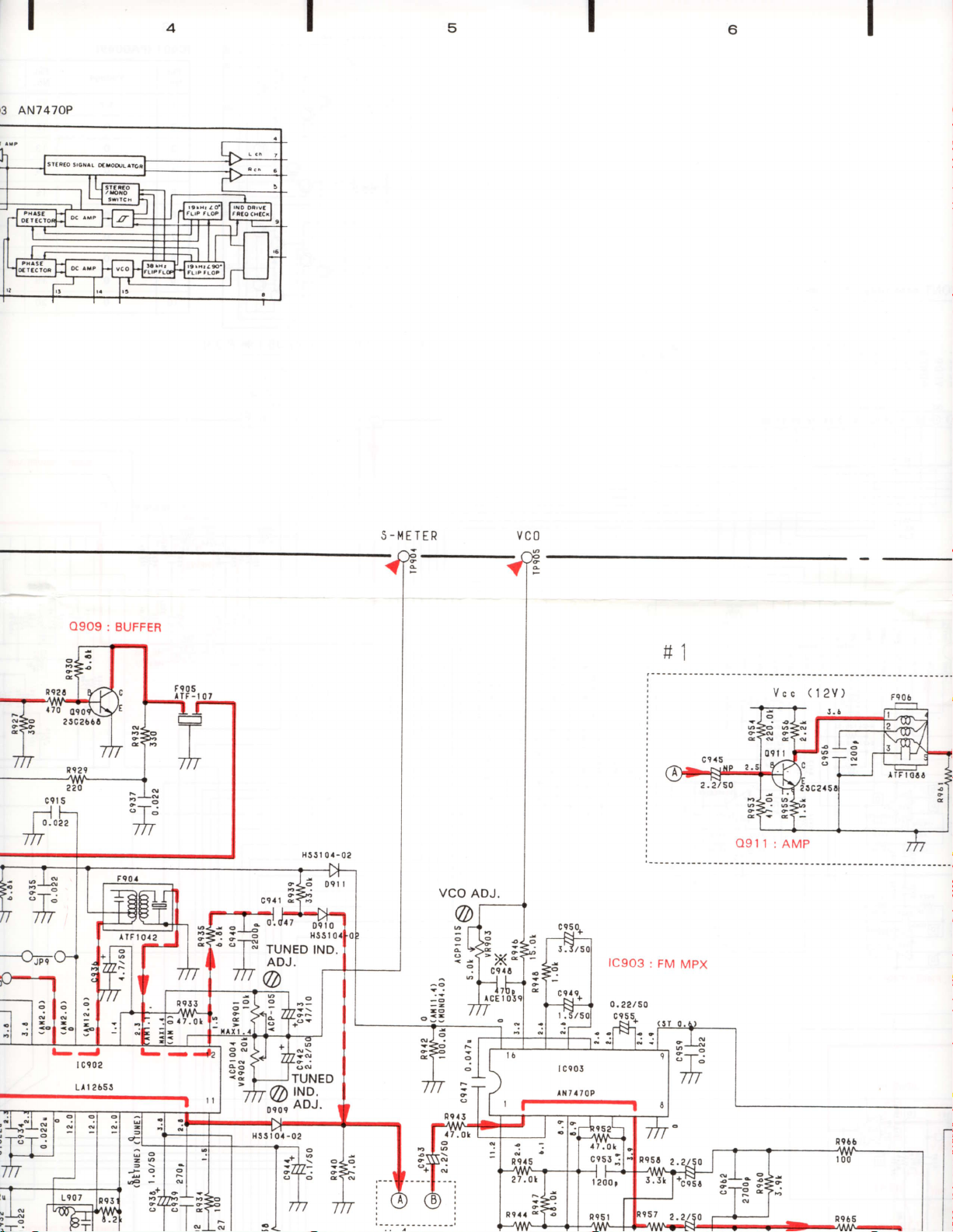
AN7470P
Ftr{ 75
Fl,l 750
(PAL)
Al.{
I
rKtt0l0
o
h r
h r
TUNER assembly
c903
+E
c904
o,o47
/25
2 Serial
aF(jO6(J
zz,z.(JF6rZ.6Z.+O
0915 : LW/MW T-
SWITCHING
^o3.gl,iY.J^ r
lrrt
026
(AWZ3938}
F. E. Module
assembly
olo
;.*.;
";r
FM FRONT
(AXO1OO2)
END
0906 : LW/MW SWITCHING
O9O7 : AM POWER
R\
SWITCH
F905
llF- il 9
s-q
tlo
I
m
O9O9
: BL
A1
b-,
C902
I
Ll | 26SS
13
AN747OP
6
O9O9:
BUFFER
'l"ldTUNEDtND.
S-I.IETER
vc0
lC9O3
rl
: FM
MpX
Vcc
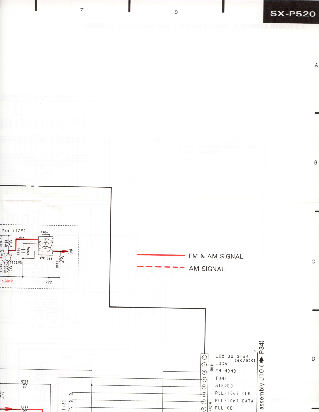
(12V)
Feo6
T=
tq.
o
;g
ITUNED
g
l8i
16
rl-l
I Ce03
lNta70P
I
6
I
I@
Vcc
(
12V)
FM
AM
&
AM
SIGNAL
SIGNAL
LC6IOO
L0cAL
2
FM
TUNE
STEREO
PLL/I067
PLL/1067
o
PLL
STARI
(9KltOK)
MONO
CE
CLK
DATA
sf
cf)
(L
I
o
-)
:
-o
E
o
o
(t)
(g
D
 Loading...