

Pioneer SX-82 Service manual
I
SERVICE
TVIANUAL
AM IFM
sxrg2
pINNEER
MULTIPIEX
ELEGTRNNIG
RECEIVER
GNRFNRAjTINil
TOKYO
*i,s,
JAPAN
t-
I
I
I
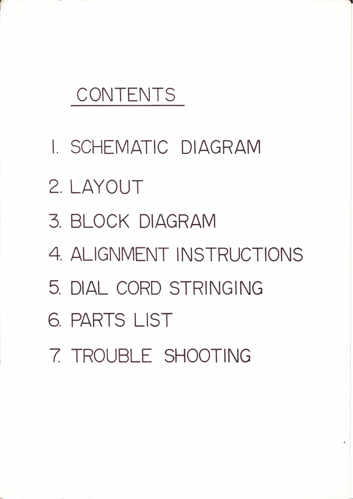
CONTENTS
I
2
SCHEMATIC
LAYOUT
3 BLOCK
4,
5.
ALIGNMENT
DIAL
CORD
DIAGRAM
DIAGRAM
INSTRUCTIONS
STRINGING
,
6
7,
PARTS
LIST
TROUBLE
SHOOTING
z
oq
p:
ft81
!a
:z
LO
=
doa
aq
4
u3
=
lt E
=il!
5:
=i
6ll
-J<
i
fr;
!==:
:i
I-o !lu, S <
Xs=? ie i
-\
uEds==,Q ft
OFL-v-
=
O
2
5q*"a"Sie
:illjtE $":
q
-\{
ftx<<@oP
eF-P 4-',t-1
a!a:-
>*_qdai-=i
6irhE-e= ;E
sdi3l9SL*=
5+€Ss;Ff;$SH
;F{!!@eqaad"
l*--vbbro-
4/tl
JJ]-]JJJ!4
q@qqqqqq+
-
!ua
'-
;a
5i I
tr===5t:
::i<'ef:
UA
-NO$q@
3R
d\
Pco
sO
P<
eqq
i F
I
I
53= 5
c
[ *
^;
'qul
6--s +
:,, 1
-
ilil= a J
S
-
li9g
ujlo^
<>{ou
sl
ro
z
?
@
O
/'d
lr)
@
o
O
L!
d
qs
SS
=
o
F
qi
Srb
Gs,
*=
ei
:t
5**3=.+
E!Fo-.,
4f
A;;SSS
5^^^^^
*do<6
a^
,if
P
qC
uS
cS
EP
:
:
jinE=
;b
.!
:Q!
:&
F
.oq<
-a
;
rlr
ii
rit
)r
:i
ll
12
@08
DO
{-i
ss
3P
J=
s3
t:
QIO
iir
@e(o
=(
5<z=
i
da
o
S
I
rE
=
tr<
do
gco
EN.
l-
l
e
6eN
<A
T
+Yqs'
tr)
NL-
o
F-
cri
-=Ij
(J
Nt-
IFJ
N3
l--xoo]
L
ISAs
i'YEl F?
#)l dnrr & |
Ot6/l@)th : I
FFH'.I
@Edgg,.*g I
rr\
i,
l-'- \{{''ooqst I
-h
,r,J 1l+
j9
J
\ --- |
-l
"1
'-.
it#rilil:(
\
l'w2
-----L
{- l F+t
)si000l
I
,-yggg
lbotvseY
zrta
\t'ost"torc
wlt?u
s
UfJIH,lfll
------
roulNo3
L€1
-z-J!--i
v
---f-
d
lr,qlri
a;
rt+itt{tl
i
#
l
E
ol
,11
:l
Y<
<3x
3*
t,t
n1zt6
^09f
tr+
*. l-
-3#
XT
>!.rtsF1__#tr'L
c!
(ol+
<l*/
m
=1-(o\
2
'l
rtr-r
:;
I
(!)l
_
<t,\
3]*
i'('-I}
SF
is
iSl
=
QSg-u*
=
o:J=E!,'Gtl
s
:- i>-q=
ll?rrqlr'1
g
-*
=-
-
<cr
: s:
iin
;'.f;
sF,
IN
Jd
lnl
l€
I
b
e
I
tr
n9zfl10l
00t3
@ \2'e-'
toe",
.is
NS
q
a-.\
tr)
@
O
O
LLI
@
o
(o
S
@
I
J
d
!
=
a
I
v-)t009
sea/
!t€tvg€d
x
,111-B-)t00s
qraA
t,
f-oa
Es
Pf;E.,5gp
L=FRS-
Et;slg$p$Fg;d
!=FEi=-:RSiiS$
!€sdEi B3:3=?; I I SS
a
'g€fs{='€€g
;8.1
A
E]
\a0L
ogi/
9
,8
o
(o
l1'jzEJ
z
o
-N
f--
o
d
(\I
o
x
l,l
E
(a
q(o
6\
z(O
s
lr)
N
o
rf)
@
O
()
L!
@
o
(o
='
l.-
O
(0
s
I
j
i0'0@r0s
X?l
v
z1sE
lil
.
F.
rO
@
()
O
tll
FX
N
s
I
t))\001e
5/,v
,vr
\-1 +
Y,€$
r\
:+f'lr
;tltffi
I
))\A0tv NT.t,
]iE(i),If,"
LO
-
-
:N
C
i
'O
Friro
Eco
FO
rH
3N
r<
3N
F.
fo
]Y^P
IT
'.
l00L
i
7JU
!l
=t=til:lil:lsli
$"Fl
i
=qaF{(
c-<' .^-o-
Elil
"Iltl
-1
(6)
;lui
1'o)
rorl
-
=ril
*iri
I
st3"
I
,l*
TE
dl.5l
\f-t
-.I o
:Lr
='L
o
_r
tl
(o
LLJ
m
(o
s
L
l
tol
<L
@
(o
s
t00t
srttcT0R
Cll'B TRIBII clt'l
ct{'8 stss
TAPt
il0ilrT0R
cfl:a
LO\{
CUT NtIfR
Elss
fir0fl
CllT
0il*l}tf
v0tlJillt
rTlJl{ll'lG
vcr
6l
(2J
vc,
fd) vco om
lgJvc'
(A\vcs
II
\sJ
W@*R6f 5ot
lr,r-
rrl
i
*
rr-l
l
m)
u.,li"ou"^ f sog Y/
I m lrd]^Tsiii
o*\i#{','l'
tAt
(sceil
\/^'v
\_-,/
l#'A
rrroror6ft,'
lsos\v,/
,r*, /A\lLgtoil
Iltltt \ \\ //,lstPlPAllol
CHANNEL
/x-nr-
I uo.
| ,o".
I
(x-rn
I uoo
I to*
I
l.
CHANNEL
B
FM
ANTENNA
AM
ANTENNA
or*
r-
aux
3000
FUSE
lt0r0r
Ut'tt
VO tTAG
strtcI0R
I
SPIAl(IR
OUTPUIS
gtrEima:':*Bj.
vsott/z6cc7
SEPARATION
CONTROL
(Pr
vt
t2ax7
.oualrzeR
vsoz 72 6Ae8
l;?.
[-AG. tptroa re
Tg€j-l:I
@,
,,r" I
I J
L"
l-
v.ot
.@
I
I
IEF
6cG7
'/2
AMT-I3
rir
vztzax?
6Fx-i)
ryr4-l
Ei i
-
r,
-
-
LEVEL coNTRoL
I
Vro
lssalrt--
AM
535-
6CW4 Vtr
t605rc
FM
88-lo8Mc T----.l
I
VE6BA6
-r
sEr-ec roR I
-
-
j
6AQ
98 7
I
8
!
VN
6AQ8
SPTAI(IR
II,IPTADTIICT
sfr.tcTtR
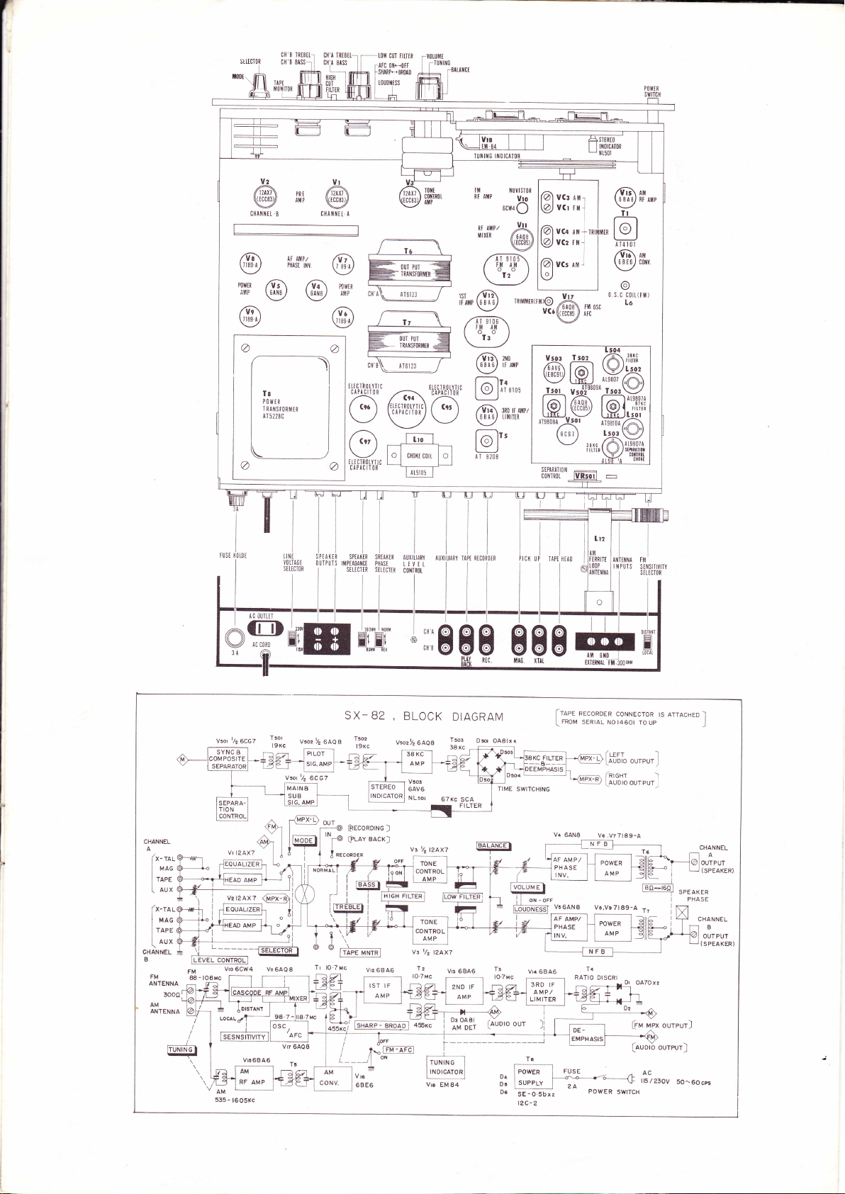
SX_ 82
1;1'.
a:;8
BLOCK
Vsoz l/2
v!
lO.7Mc
6Ae8
TONE
CONTROL
AMP
t/z
T2
DIAGRAM
T5oi
38 Kc
67(c SCA
l2ax7
vB 6846
2NO IF
F I LTER
AMP
B
Ds
0A8lx4
HH8
i/=
ItolrrM E I
| |
mtDNEssT
I r--l
lOTMc
on-o.t
,ort'rroo
Iraee
l_
|
V5
I
l
I
rnov
64N8
lr2
AM
ItRRITi
r00P
TNTIIII{A
Reconorn
srnrnl
NFB
Ta
RATIO
lflT${t{A
III PUTS
coNNEcroR
No
1460r ro
(urr
[auoro
(nrcnr
lauDro
V6.V?7189-A
DISCRI
oureur
ouTPUT,l
(rru
(auorb
AC
l15/23OV
rs arrncneo
up
I
J
)
rr,lnx
oureur)
ournrr)
I
)
CHANNEL
--{do#,u'
u (sPEAKER)
i
PHASE
I
50^60cps
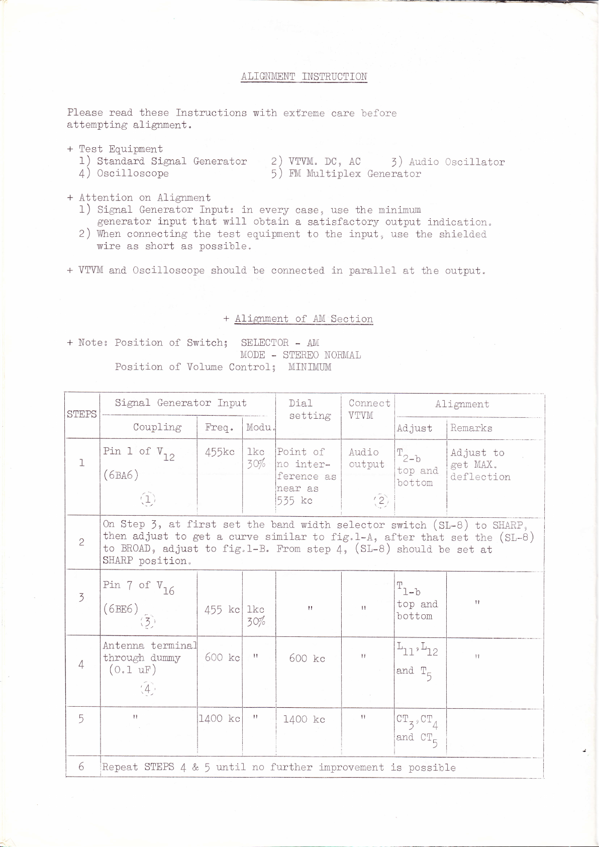
ATIGNMENT
INSTRUCTION
Please
attempting
+
+
+
VTVI\/I
+
Note:
read these Instructions
with
alignment.
Test
Equipment
1)
Stand-ard- Signal Generator 2) VTVI,{"
Oscilloscope
4)
Attention
1
Signal Generator
)
generator
2)
\Mhen
wire
on
Alignment
input
connectlng the
as
short as
Oscilloscope
and
Posi-tion of
Input: 1n
that will-
test
possible"
should-
obtain
equipment to
be connected.
+
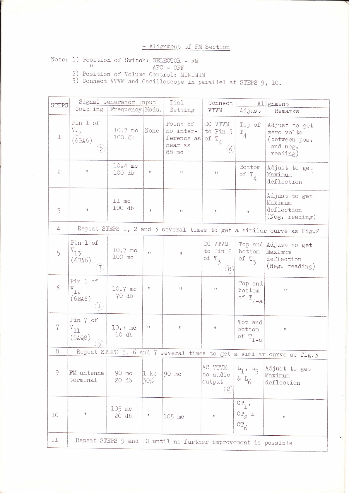
Alignrnent of
Switch; SEIECTOR
MODE
cmutoc I
rl:tr
LJ
*.1
Position of Volume
Signal Generat
I
I
------
oupl
C
lng
;or
Control;
fnpu
Freq.
L
tJ
;---'
Mod-u
l_
Pin 1 of
(
6ra6
)
a
,l;
\
V-
L2
',
-.
455kc
I
|
I
1kc
tV"
extreme
fl,[ Multiplex
5)
every
case
a
STEREO NOR]VTAL
I\II1IIIMUM
Dial
setting
Point
no
inter-
ference
near
kc
515
care before
DC, AC
Generator
use
,
the
satisfactory
input,
the
parallel
in
Secti_on
4lll
AIVI
Connect
VTVM
of
as
as
Audr-o
output
-
Aud-io Oscillator
1)
minimum
output ind-ication.
use
the shield-ed
12'
at
Ad-just
T,-,
r-
a"
top
bottom
-
the
Al ignment
tJ
and-
output.
lRemarks
Ad-just to
ge
Ceflection
t
IIT"AX
"
W
then ad-just
to
SHARP
Pin
(5m6)
lAntenna
through
, I
+
5
I
(o.t
BROAD,
position.
of
7
:1
termina
dummy
uF)
,4
n
ad-just
Vrn
to
rst set
a
;et
€
to
455
b,OU .[cc
1400
,-r-
5
the
rve
cu:
fig
kc
kc
si
1-B"
"
lkc
1q"
il
"
L no further
t
*"d *idth
milar
From
I1400kc
rl
!l
:l
il
i1
500
to
step
il
kc
irnlrovement i
elector F
=
f1
9,1-A ,
(sl-e)
4
,
I
witch
el
ter
that
should be
(sl-e)
set
set at
to SHARF,
the
p
(Si,-A
-B)
Tt-l
top
il
n
"
and
bottom
L1l'L12
and T-
CT-
iand CT-
t)
-s
)
CT,
,
)+
-possib
??
Le
\
Noter
STEPS
I
2
1
4
1)
Posltion
2)
Position
Connect
1)
SLgRal.
Coupl
Pin
I
1/
'l'4
(
5ra6
il
ll
*t""t
Generator
ing
of
)
:5':
t
of
Switchr
of
Volume
VTVIVi
Frequency
I
I
I
I
I
IEPS
10"7
100
10,{
100
11mc
roo
1,
and.
mc
d.b
mc
d.b
d-b
SELECTOR
AFC
Controlc
Oscil-loscope
Input
_
ii\,lod_u.
None
il
l"
I
2
r,nd-
1
everal
OFF
IVIINI1vIUM
in
Dial
Setting
Point
no
ference
near
BB mc
of
inter-
as
il
il
FM
parallel
Connect
VTVl\{
DC
to
as
of
tim
U
VTV]!,T
Pin
TA
il
It
to
-T
get
',5'.
at
5
Lil
I
a
".
STEpS
9,
Alignment
.
Adjum
Top
of
T
-4
Bottom
of
T.
/t
-f
st_mt-Ia
10"
Ad-just
zero
to
volts
(between
and-
neg"
read.ing)
Ad-just
Maximu:n
def lection
Ad-just
Maximu-m
to
to
d.efl-ection
(Neg.
curve
read-ing)
as Fig.2
get
pos"
get
get
_
10
5
6
t-7
I
B
9
Pin
I
v__
L)
(eru5)
Pin 1
oLz
(
5ra5
)
Fin
7
vtt
(
5nqe
)
Repeat
FM
antenna
terrninal
il
of
tri:
of
,1
of
''.9
10"
100
10.7
70
10"7
60
STIEPS
90
20 db
105
20 d_b
7
mc
db
d.b
5,
mc
mc
mc
mc
mc
5
il
il
il
and-
lkc
toTi
It
several
7
90
f05
mc
il
il
mc
DC
VTVI\I
to
il
time
of
AC
to
Pin
T-
t
il
lt
to
VTWI
aud.io
get
output
il
Top
and-
Ad.just
2
bottom
of
ibl
Top
bottom
of
T^
Top
bottom
of
T-
?" simil ar crrr\ro 2s ficn 4
Lr'
&L,
nm
ttr'
cr^
I
nm
o
/ nt
tl)
.
-
T-
"j
&
)
and
')
L-CL
and-
L-a
Maximum
d.ef
lection
(N"g,
t?
ll
Ad-just
Maximirm
d.ef
lection
ll
read.ing)
to
to
get
get
11
Repeat
STEPS
9
and_
10
mtil
no
furth
provement
er
l-mprovemen
possible
1s
I
I
 Loading...