

Page 1
,t
'r
t
3s=r--*-**
*':*
o-si'
€I
-iiJ\
!l
(0rrroruEen
:E*
.{F
Page 2
AM
/FN
STEREO
RECEIUER
s
450
(=
lE
o-
LN
HG
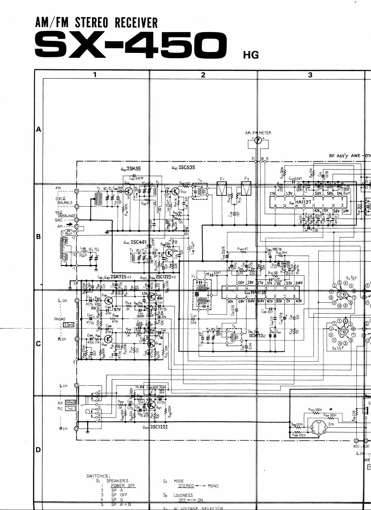
RF
AssT
AwE
lu,Quz2SA?25
IK
a
-E
&
0,o3
2SC+61
xz
ozor
2scl222xz
zo{
2SCt 222
T
.Y1
C!
a
J
o
,2
,(q
d-
(o
5
c.l
cw
6
l0v
5
d
e
o
6
(o
F
(-)
9
{.
ql
<!,
@
r
ITCHIS
SW
SI
1
2
3
;
SPEAKER
S
POWE R OFF
SPA
OFF
SP
MODE
Ss
So
LOUDNESS
STEREO
+---_
l'10N0
Page 3
3
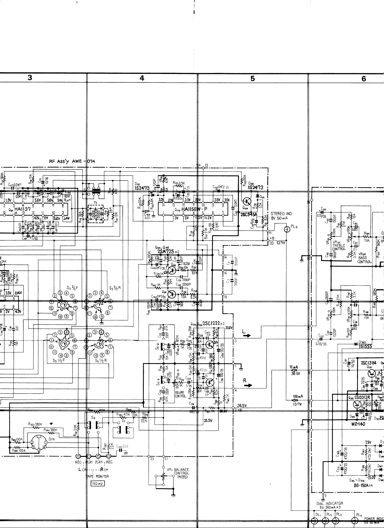
AwE
Asst
RF
Cr1.0.4'/:S
6
o,orHAlll3?
INO
o
e
.
l--'
J-P
I
i.iT;
STEREO
mA
50
EV
6l
C-)
:
2
E.
o.
ol
d
H.;
'T=
i
Cw\.41hs
F+
o=-F
"5
;q
F*
F
6-
3l
9,
N
(-)
F
G.
tar
:<
o
s
CW.
t.
et
i-
)<,
LO
e
a
n4
Ht
n
2SCl222 xz
-t=fr
ln ra
'rtlu
'd
H
I
-'l
I
I
33.611
I
--
s
I
:<
o
o
3
I
o
G
>
I
o,
d
?sct3
Qrot
q3or2503l3R
8+
Dx
I
+
d
@
e
C2a6
C.O I
VRl
BALANCE
CONTROL
1tl(85)
DtAu
8V
tt't0tCAT0R
x3
300mA
v)
C)o
5t
tr3-
h A
-
ugot
Uxos
l50Ax+
DS-
01
--25.
Page 4
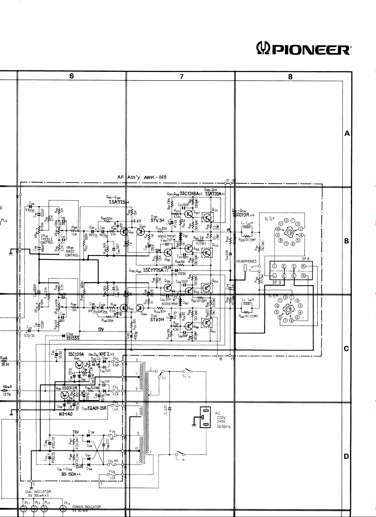
ASs'y
AWK
-
(DrrtoNEER"
009
0
,PLS
eu,,Qzor
CJ
nJ
o
E
ol
qJt
E
-
o
9
6
I
I
o
&.,
I
E
oros,ezoe
o
o
lr
P
E
>
o,
-+'
9.
d
2SCl3
8/|.
Qror
Cmz.
Crro
a-a+ ^+a
{,4s
Dror,ft12 tO! 2
Rlor
33
93_or
21t++
xz
FU
)cD
>9
t
r"5
.T
25
=
tltl
C
l
=
ADilusrHEN-r
c?or22P
5At-4;
ADJUSTI'IENT
gt gn"
2s
c
I
itAtiba',
x+
13R
.--r*
+
(1/2w)
=
:s
5
9
ft4s)o(r/2w,_|.a
L2 14H
l0
Rzoo
(llZWl
s'hF
t
@@eo
@O
@@
|
DIAL
EV
INDICATOR
x3
300mA
ocor250313R
U)
C)o
5cr-
c!-
n n trr.vl n
-
UIOB
UXos
3
c\r
O
.<r-
U3o8
Page 5

ASs'y
,0.6V SW
AWK
-
069
3H
Rll
E2K
=
ADJUSTilENT
c?os22P
Qo,r,Qos
2SCl3tSAxz
a1
+
=
.s
a
2g\ltQlxz
.--*
c-
R.,'o('-uig
E.
$
o
o
E
.J
S'
hF
t
c@
to
I
eo
@@
:<
o
9
-o
I
o
E
>
O.
-+'
o,
d
zSCl3
Qror
tr)
c-)
-
c!
s
O
q3o,250313R
3
c{
O
h A
Ujos
.f
(r
.iv.vt
!
U30t
v>
C)
5t
c!-
Dor,D312
8+
Broijf 9qo' _FU:
n
U3o6
shs'1i++
xe
2
lOE
>9
t
r<o
r.5
.T
Crn
=
ADilUSTtlENT
Sfvcn
22P
O
d
L)
d-
(r
L2 11H
Rzco
l0
(llZWl
DIAL
8V
INDICATOR
x3
300mA
Page 6

HA1.l37
o,
RF
Ass'/
AWE
o
o
t,
€
o
(ji
L\V
a',e
Yc-
-A
ttr
Qns
HAll
cci
r
&-
C3
l-.
I"
I
.iT;
i
o
E
STEREO
mA
50
8V
IND
a
o
o
s
)<
o
9
H'*
'T=
i
H
)<
o
o
ll
o
&
2SCl222
xz
<f,"
o.
o
<.,
c:,
-l-r33.511
I
tAs
J
2
I
E
I
I
>
=
9,
9.
t
?scl3
Qrot
o3o,250313R
8+
Dto,l
l{l
s
tdt
'b
3
Rzia
iOoir
:
SIONAL VOLTAGE
VI
I
G mA : DC
V : DC VOLTAGE
CURRENT
AT
AT NO
<:
N.
@
E
REC-
NO
Li
AT
i
IGNAL
l'10Nlr0R
EAKER
NK
flK
t-249
J.U I
OUTPUT 10.9V
/EQ
I ffi
(lKHr)
u^'Edh+HtE
I
1M(85)
DIAL
8V
INDICATOR
x3
300nrA
2sv
v)
<?@
5t-
tr-
3-
-
Dror
Drs
N-l50Ax+
D6
3
6
Page 7

VCrlCr
P1'-Jlc-'-#lF
ll;ia
C,n4
AWE
Ass'7
RF
2SC535
oro2
r02
a-
lo
ld
5
)<
o
9
a,
lj
a.
l=
J-
h
or-HAl.!3?
LA
vc,
rct
la,Qnz2SA?25
IK
a
-o
0,03
xz
2SC+61
ozo3,
AP
s
a
T
.Y{'
(v
E
J
-
o
Lr)
f,
C63100/16'
=l Rr+s24K
(
l0v
6
d
r
Ua
6
(o
5
o
o
O
o
d
(J
d
o
@
S:
ITCHES
SW
SI SPEAKER S
1
2
3
52
53
I
2
3
+
Sa
;
POWER
SPA
OFF
SP
MUTING
FM
-'t
0N
FUNCT|0N
At1
Ft1
PHONO
AUX
TA
Pt MON
-Q.EL-
OFF
OFF
tTO
oN
2SCt 222
MooE
Ss
Ss
LOUDNESS
Ac VOLTAGE SELECTOR
S4
RESISTORS:
lN
OTHERWISE
CAPACITORS
lN,4F
R
STEREO
4_
220V
1/4W,
OHM
,
:
UNLESS
++
240v
NOTED
0THERW
l'10N0
t\o/o
TOLERANCE
K=K.CI
ISE NOTED
M=MC}
,
UN
P=
pF
'->
mA
:
DC
:
STGNAL
VI
I'
V : DC VOLTAGE
VOLTAGE
CURRENT
AT
AT NO
AT
N0
Page 8

F
?
ADJUSTMENT
9.
9.1
AM
SECTION
1.
Through a 1k ohm
signal
Set for 40OHz
2
Connect
(L
Set
4.
Set AM signal
dication
Adjust
5.
voltmeter.
c).
Set AM
dication
generator
AC
or
R).
FUNCTION
point A (600kHz).
to
T6 for
signal
point C (1,400kH2).
to
to the
at 100dB
voltmeter
switch
generator
maximum
generator
resistor,
AM antenna
and 3O%
to TAPE
to AM
and SX-450
indication
and
connect
terminal.
modulation.
REC
position.
SX-450
an AM
iack
dial inon
AC
dial in-
7. Adjust TC4 for maximum
voltmeter.
8.
Again
indication
9.
Adjust bar
dication
10.
Return AM signal
indication
11. Adjust
voltmeter.
12.
Repeat steps
AC voltmeter indications
set
AM signal
point
to
antenna core for
on AC voltmeter.
point
to
for
TC5
generator
A.
generator
C.
maximum
4-11 to
AC
eliminate variations in
at
voltmeter
sx-450
indication
and
SX-450 dial
maximum in-
and
SX-450 dial
indication
A and
noint
on AC
on AC
C.
q'
.{
)
signal
generator
AM
tr@
q
1
25
Page 9

9.2 FM
1. Through
2.
3.
4.
5.
6. Adjust
7. Set
8.
SECTION
FM signal
antenna
IO0%
and
Connect
TAPE REC
FUNCTION
Set
switch
Set
indication
Adjust T3 for
voltmeter.
indication
adjust
AC
Set
indication
to OFF.
FM
FM
T1
voltmeter.
FM
300 ohm
generator
terminals
modulation.
AC voltmeter
jack
signal
point A (90MHz).
to
lower
T5
on AM/FM meter.
signal
and
signal
point C (106MHz).
to
dummy
to the 300
and set for 4OOHz
(L
or
switch
generator
maximum indication
core for
generator
T2 for maximum
generator
antenna, connect
and distortion
R).
FM
to
for
and MUTING
and
SX-450 dial
center
9dB output
indication
and
SX-450 dial
ohm FM
100dB
at
meter
of scale
on
to
AC
and
on
9. Adjust
indication
10.
Again set FM
indication
11.
Adjust
indication
12. Repeat
sensitivity
13. Adjust
14. Detune
for center
15.
Set SX-450
and
scale indication
16.
Set FM
adjust T5 upper
17.
Repeat steps
mum
TC3, then
"t4
to noise
adjust FM
distortion
TC1
on AC voltmeter.
signal
point
to
T3, then
on
steps 8-11
points
at
for maximum
of scale
dial indication
signal
14-16
generator
A.
T1 and
AC voltmeter.
to eliminate
A and C.
only
and adjust
indication
signal
on
AM/FM
generator
core for
eliminate
position.
and TC2 for
and SX-450
for
T2
variations
sensitivity.
T5 lower
on FM
point B (98MHz)
to
generator
output
minimum
for
meter.
to 60dB
variation in
*u"i*rr-
dial
maximum
in
core
meter.
center
distortion.
of
and
mini-
A |
J"
/
'a
tl
ACvoltmeter
FI
a)
T2
T1
Distortion
FM
signal
generator
tr@
0*-
f'{
TC1
l\\
t
Page 10

MPX
9.3
1. Through 300 ohm
FM signal
SECTION
dummy antenna,
generator
terminals.
2.
Connect multiplex
modulation
terminals
signal
3. Connect oscilloscope
signal
to TP
pilot
output
(No.
13) of circuit board.
and
to 300 ohm FM
generator
FM
of
signal
to extemal
generator.
horizontal input
vertical
input via
connect
antenna
MPX
to
probe
4.
Set SX-450 dial
FM signal
cation
5. With
on AM/FM
FM
indication
generator
signal
generator
VR1 so that lissajous
67.5kHz
R
stationary
deviation and
adjust T4 for minimum distortion.
becomes
With MPX signal
6.
+
L
deviation,
to 98MHz
for center
meter.
unmodulated,
pattern
as shown
generator
sx-450
and adjust
of scale indi-
adjust
on oscilloscope
in Fig. 12.
modulation lkHz,
pilot
7.5kHz
tl'
'a
t
AC voltmeter
Dummy load
Oscilloscope
Distortion
FM
signal
MPX
generator
generator
signal
meter
I
I
r|}
l'
I
I
I
I
I
I
I
I
I
i
Fig.12
Page 11

9.4 POWER
1. Set
2. Nothing
3.
4.
BASS
position.
jacks
should
terminal.
A DC
between
Left
channel.
Cut the
15mV.
of
channel
should
SX-450 and
be connected
voltmeter
terminal
jumper
AMPLIFIER
and TREBLE controls
be connected
and
lead,
SECTION
an 8
across the
should
number
18
1+1,
if the
DC Voltmeter
to the
ohm dummy
be
connect
19
1+;,
(-)
l7
voltage
(IDLE
20
CURRENT}
ro center
INPUT
load
SPEAKER
across
(-)
for
Right
than
less
a r''
for
fi
j**'
ita
{
#
fNt
ed
Page 12

sx-450
)10.
Remove
1. Turn
DrAL
the Front
tuning drum
from X direction
2. Tie one end
tuning drum
setscrew and temporarily
ing
from shaft).
drum
of cord to stud on
(more
3. Pass cord through
tum around
sequence:
4. Wind
cord clockwise
turns around dial
3
the
pulley
5. Wind 3 tums around
so that the
6. Turn TUNING
1
motion. then trim
I
7. With tuning
t
'
8.
needle to
dial
Apply
cord is under tention.
capacitorblades
starting
laquor to tied
CORD STRTNGTNG
(See
panel
in
easily
pulley
pulley,
A-Dial
shaft, then route to
knob and confirm
off excess
page
14, 15).
fully clockwise
Fig. 13).
inner section of
performed
removing tuning
opening,
route in the
then
needle-pulley B-C.
(as
viewed from rear
pulley
dial
and tie
normal cord-
cord.
fully closed, move
point
(left
edge
ends of cord.
(as
viewed
by loosen-
make a half
panel)
pulley
D.
to spring
scale).
of
DIAL NEEDLE INSTALLATION CAUTION
Metal
If this
fingerprints
remove
desirable
corrosion, take exteme care not to touch the
metal
portion
of
dial
section is
and other
from
dirt
aventurine
in terms of
section when
pointer
plated.
is
touched directly by
impurities, it is
finish.
difficult to
As this
both appearance and anti-
handling
Dial needle
the dial
needle.
hand
is not
or
Pulley
Tuning
End:
D
drum
Spring
Tie to spring hook
hook
Dial
shaft
Stud
Start:
Fasten
on end of
cord to start
the
'rl
\ -'
..'
,.'l
I
Pulley
I
C
Fis.13
29
 Loading...