

Page 1
POWERED SUBWOOFER
S-W80S
THIS MANUAL IS APPLICABLE TO THE FOLLOWING MODEL(S) AND TYPE(S).
Model
S-W80S
MYXCN AC220–230V
RemarksPower RequirementType
ORDER NO.
RRV2296
CONTENTS
1. SAFETY INFORMATION....................................2
2. EXPLODED VIEWS AND PARTS LIST .............3
3. SCHEMATIC DIAGRAM..................................... 6
4. PCB CONNECTION DIAGRAM .........................8
5. PCB PARTS LIST.............................................10
6. ADJUSTMENT.................................................. 10
PIONEER CORPORATION 4-1, Meguro 1-chome, Meguro-ku, Tokyo 153-8654, Japan
PIONEER ELECTRONICS SERVICE, INC. P.O. Box 1760, Long Beach, CA 90801-1760, U.S.A.
PIONEER EUROPE N.V. Haven 1087, Keetberglaan 1, 9120 Melsele, Belgium
PIONEER ELECTRONICS ASIACENTRE PTE. LTD. 253 Alexandra Road, #04-01, Singapore 159936
PIONEER CORPORATION 2000
7. GENERAL INFORMATION .............................. 11
7.1 DISASSEMBLY .......................................... 11
8. PANEL FACILITIES AND SPECIFICATIONS
....................................................................13
T- ZZA APR. 2000 Printed in Japan
Page 2
S-W80S
1. SAFETY INFORMATION
This service manual is intended for qualified service technicians; it is not meant for the casual
do-it-yourselfer. Qualified technicians have the necessary test equipment and tools, and have been
trained to properly and safely repair complex products such as those covered by this manual.
Improperly performed repairs can adversely affect the safety and reliability of the product and may
void the warranty. If you are not qualified to perform the repair of this product properly and safely, you
should not risk trying to do so and refer the repair to a qualified service technician.
WARNING
This product contains lead in solder and certain electrical par ts contain chemicals which are known to the state of California to
cause cancer, birth defects or other reproductive harm.
Health & Safety Code Section 25249.6 – Proposition 65
NOTICE
(FOR CANADIAN MODEL ONLY)
Fuse symbols (fast operating fuse) and/or (slow operating fuse) on PCB indicate that replacement parts
must be of identical designation.
REMARQUE
(POUR MODÈLE CANADIEN SEULEMENT)
Les symboles de fusible (fusible de type rapide) et/ou (fusible de type lent) sur CCI indiquent que les
pièces de remplacement doivent avoir la même désignation.
(FOR USA MODEL ONLY)
1. SAFETY PRECAUTIONS
The following check should be performed for the
continued protection of the customer and service
technician.
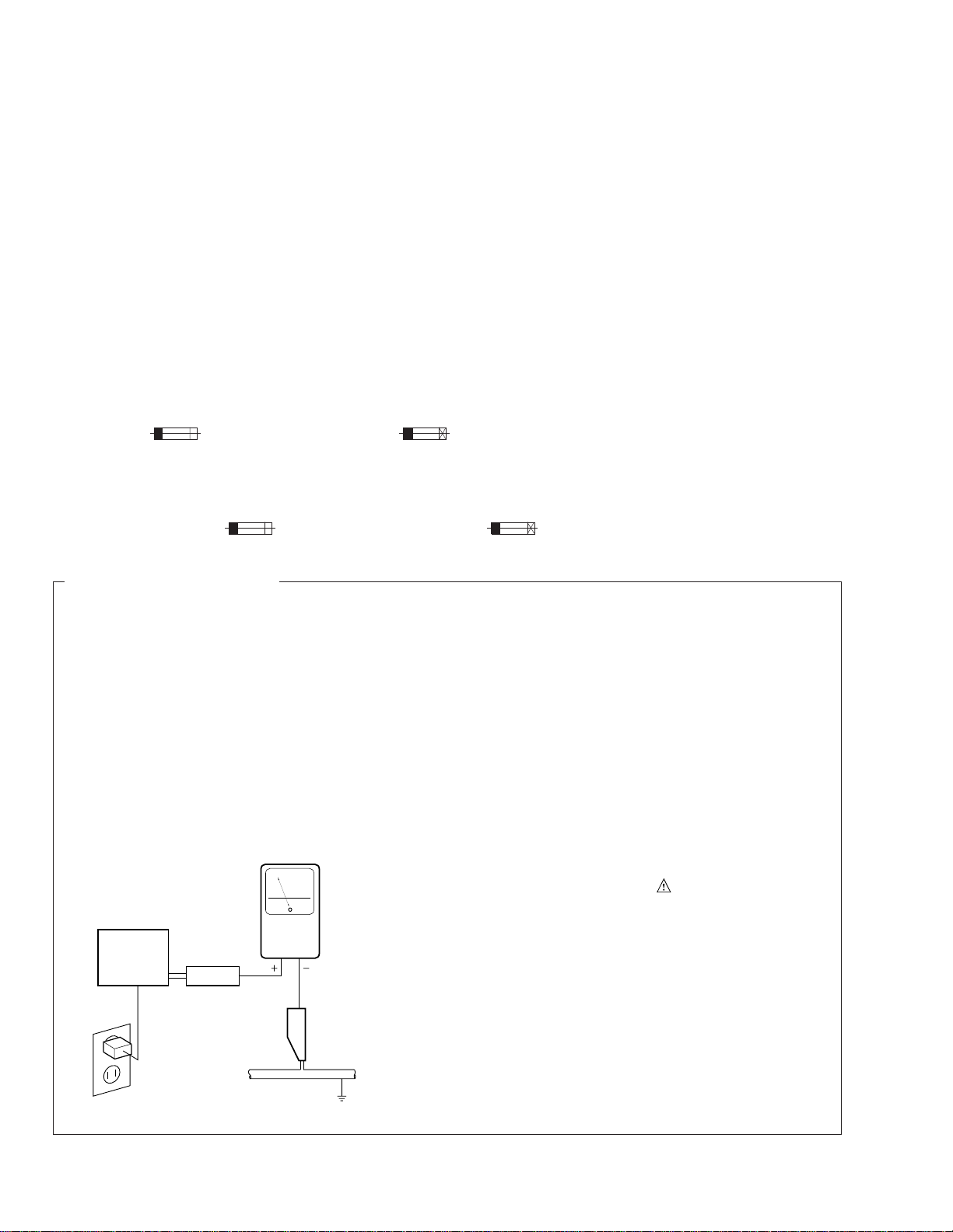
LEAKAGE CURRENT CHECK
Measure leakage current to a known earth ground
(water pipe, conduit, etc.) by connecting a leakage
current tester such as Simpson Model 229-2 or
equivalent between the earth ground and all exposed
metal parts of the appliance (input/output terminals,
screwheads, metal overlays, control shaft, etc.). Plug
the AC line cord of the appliance directly into a 120V
AC 60 Hz outlet and turn the AC power switch on. Any
current measured must not exceed 0.5 mA.
Reading should
not be above
0.5 mA
Earth ground
Device
under
test
Also test with plug
reversed
(Using AC adapter
plug as required)
Leakage
current
tester
Test all exposed
metal surfaces
AC Leakage Test
ANY MEASUREMENTS NOT WITHIN THE LIMITS
OUTLINED ABOVE ARE INDICATIVE OF A POTENTIAL SHOCK HAZARD AND MUST BE CORRECTED BEFORE RETURNING THE APPLIANCE
TO THE CUSTOMER.
2. PRODUCT SAFETY NOTICE
Many electrical and mechanical parts in the appliance have special safety related characteristics. These
are often not evident from visual inspection nor the
protection afforded by them necessarily can be obtained by using replacement components rated for
voltage, wattage , etc. Replacement parts which have
these special safety characteristics are identified in
this Service Manual.
Electrical components having such features are
identified by marking with a
on the parts list in this Service Manual.
The use of a substitute replacement component which
does not have the same safety characteristics as the
PIONEER recommended replacement one, shown in
the parts list in this Service Manual, may create shock,
fire, or other hazards.
Product Safety is continuously under review and
new instructions are issued from time to time. For
the latest information, always consult the current
PIONEER Service Manual. A subscription to, or additional copies of, PIONEER Service Manual may be
obtained at a nominal charge from PIONEER.
on the schematics and
2
Page 3
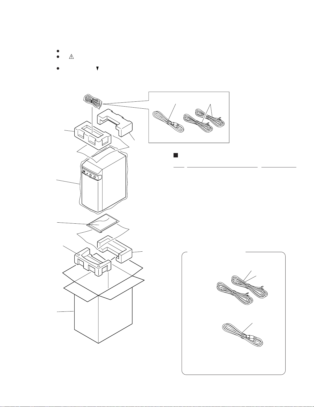
2. EXPLODED VIEWS AND PARTS LIST
NOTES : Parts marked by “ NSP ” are generally unavailable because they are not in our Master Spare Parts List.
The mark found on some component parts indicates the importance of the safety factor of the part.
Therefore, when replacing, be sure to use parts of identical designation.
Screws adjacent to mark on the product are used for disassembly.
2.1 PACKING
56
4
(3/4)
4
(4/4)
PACKING PARTS LIST
Mark No. Description Part No.
S-W80S
1
3
4
2
(1/4)
4
(2/4)
1 PO Bag (680×880×0.04) 07–490031–00
2 Carton Box 07–390035–00
3 Operating Instructions 12–540052–11
(English/French/German/Italian/
Dutch/Swedish/Spanish/
Portuguese)
4 Packing Style foam 07–090000–11
5 Speaker Cord 02–100066–02
6 RCA Cable 02–300067–02
ACCESSORY ITEMS
÷ Speaker cords x 2
(02-100066-02)
÷ RCA plug cord x 1
(02-300067-02)
Red
Black
Black
÷ Operating instructions x 1
(12-540052-11)
÷ Warranty card x 1
3
Page 4
S-W80S
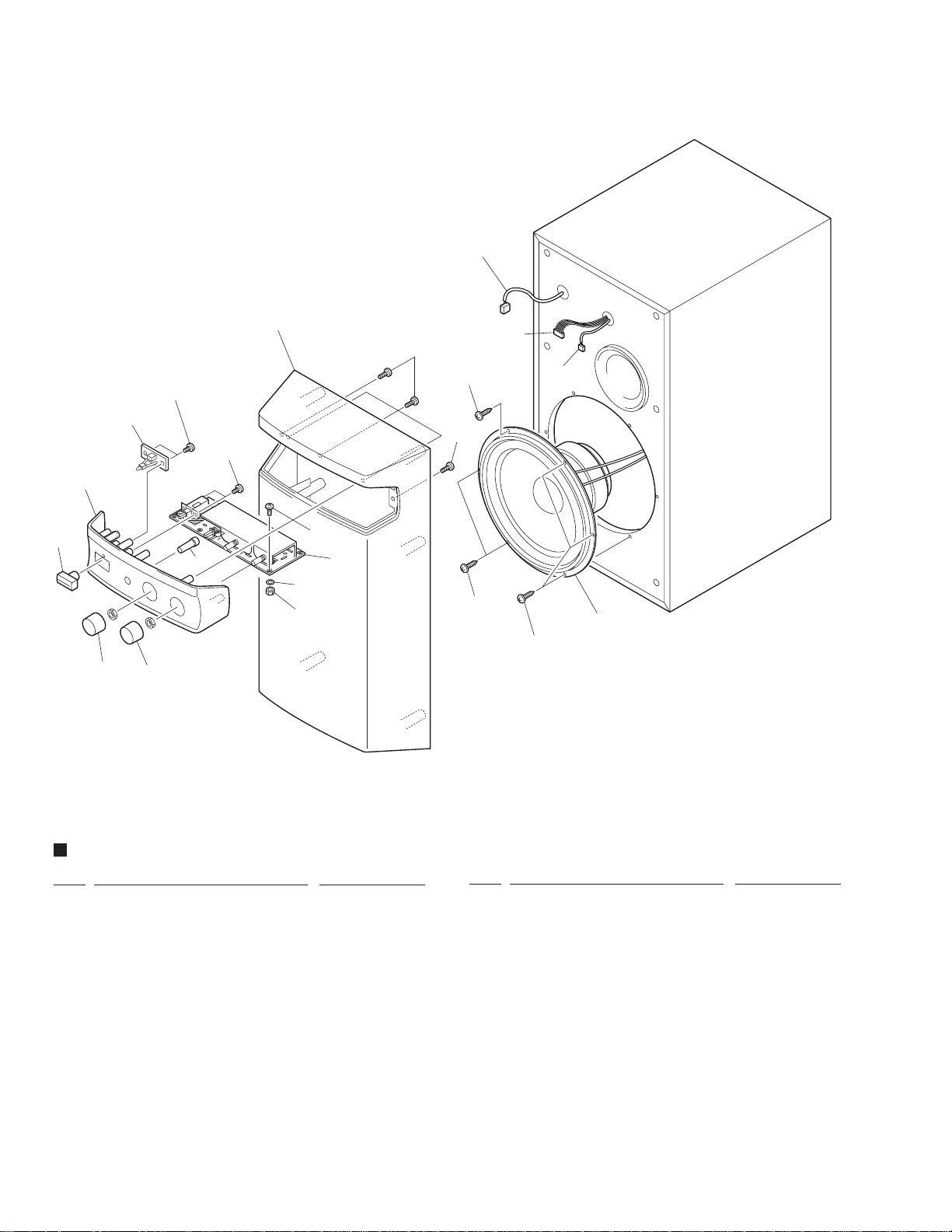
2.2 FRONT SECTION
18
10
12
2
1
11
3
14
2
3
4
PWRSW
A
LED
1
7
8
LED
SG
LPF0
K
–15V
PG
+15V
SW1
PHASE SW
W8
W10
SUB LEVEL
W3
R8
LPF CORNER FRQ.
17
PC
IN
SG
C1
M4
+
R11
C2
C7
R10
VR1
W4
4
13
16
15
1
9
1
5
6
FRONT SECTION PARTS LIST
Mark No. Description Part No.
1 Screw (M4×18) 23–106302–18
(for woofer speaker drive)
2 Screw (M3×12) 23–104100–12
(for control panel)
3 Screw M3×6 23–104100–06
(for Power switch, LED PCB assy)
4 Control Panel 20–101022–01
5 Volume Knob (LEVEL) 20–101023–01
6 Frequency Knob (TURNOVER) 20–101024–01
7 Push Button (POWER) 20–101026–01
8 Push Button (PHASE) 20–101027–01
9 Woofer Speaker Driver 15–308006–00
10 Grille Assy 00–101021–01
4
Mark No. Description Part No.
11 Audio Cable 02–390034–03
(for INPUT PCBAssy M1 to FILTER PCB Assy M4)
12 Connect Cable 02–390035–06
(for POWER AMP PCB Assy J1 to
FILTER PCB Assy M5)
13 FILTER PCB Assy 00–011011–60
14 LED PCB Assy 00–011014–10
15 Nut (M3) 24–119003–00
16 Washer (M3) 29–103292–00
17 Screw M3×6 23–104611–06
18 Cable 02–390032–02
(for INPUT PCBAssy M2 to FILTER PCB Assy M6)
Page 5
R12
R11
Q1
Q2
D3
D2
C6
R8
R7
3
R9
C11
C5
R16
0 '
G
D4
C7
W3
BR
J2
C12
R5
R3
R2
R1
U1
C10
C2
C9
C8
J1
+15
PG
–15
IN
SG
R6
D1
R4
C
C'
B
B'
A
A'
C4
C3
W2
W1
+
+
+
+
+
+
+
+
+
5
1'
XFR
SP+
J3
XFR
C.T
AC
R17
+
–
R14
R13
R15
R10
1
3 '
4 '
2
4
0
5 '
2 '
PIONEER SW–80S POWER AMP PCB ASS'Y ZENIX U.S.A (C) 1999 REV. HA
R2
R5
R4
R3
J2
E
G
+
+
+
––
J3
M3
H
C3
L1
H
H
AC IN
F1
N
M2
M4
PRIMARY
ZENIX U.S.A.
REV. DA (C)1999
PIONEER SW–80S INPUT PCB
C4
R9
R8
R6
M1
CG
SG
OUT
R1
R7
C2
C1
J4
IN
W1
W2
OUT
13
21
3
1
10
9
3
3
3
3
2
4
7
7
7
3
5
6
5
22
14
15
13
11
12
11
23
11
12
25
12
17
20
24
16
17
18
19
8
8
14
15
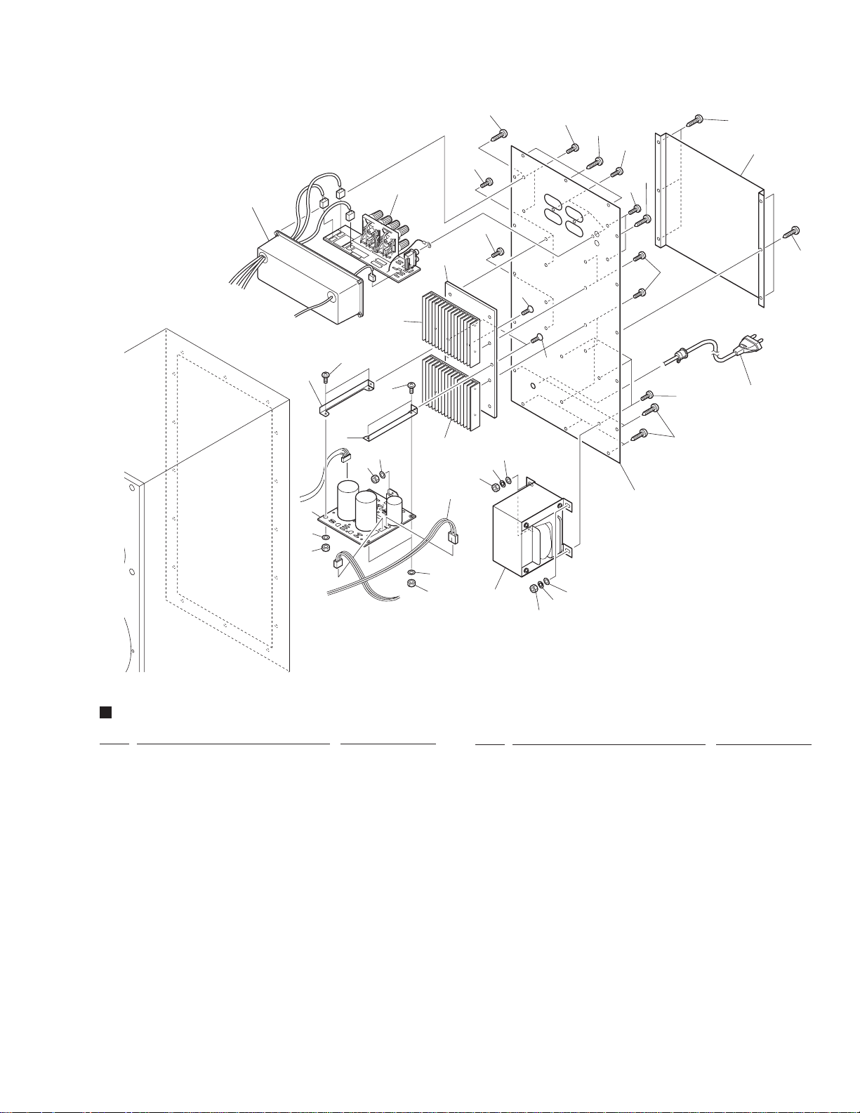
2.3 REAR SECTION
S-W80S
REAR SECTION PARTS LIST
Mark No. Description Part No.
1 Rear Panel 21–301031–01
2 Safety Plate 21–301032–01
3 Screw (M4×20) (for rear panel) 23–106302–20
4 Screw (M4×12) 23–106111–12
(for power transformer)
5 Screw (M3.5×12) 23–105104–12
(for plastic hermetical box)
6 Screw (M3×12) 23–104102–12
(for I/O jack, RCA jack)
7 Screw M3×14 23–104111–14
(for heat sink to rear panel)
8 Screw M3×6 23–104611–06
(for POWER AMP PCB Assy)
9 Screw (M3×10) 23–104211–10
10 Screw (M3×12) 23–104211–12
11 Nut (M3) 24–119003–00
(for POWER PCB Assy)
Mark No. Description Part No.
12 Washer (M3) 29–103292–00
(for POWER PCB Assy)
13 Nut (M4) (for power transformer) 24–114004–00
14 Spring Washer (M4) 29–204202–00
(for power transformer)
15 Washer (M4) 29–104202–00
(for power transformer)
16 Plastic hermetical box 20–601025–01
17 Heat Sink 21–101037–01
18 PCB Bracket L 21–301043–01
19 PCB Bracket R 21–301052–01
20 Plate (for heat sink) 21–101057–01
21 Power Transformer (230VAC) 01–523054–71
22 AC Power Cord 02–300065–02
23 Red/White Cable 02–390012–02
(for woofer speaker driver)
24 INPUT PCB Assy 00–011012–40
25 POWER AMP PCB Assy 00–011013–80
5
Page 6

1
234
S-W80S
3. SCHEMATIC DIAGRAM
A
B
C
OUTPUT
LEFT CH.
SPEAKER
OUTPUT
RIGHT CH.
SPEAKER
LINE OUT
AMP
AMP
LINE IN
+
–
+
–
+
–
+
–
M4
J4
J3
J2
INPUT PCB ASSY
A
(00-011012-40)
C2
390p
C. CAP
±10%
C1
390p
C. CAP
±10%
R1
15k
R7
1k
R6
1k
R8
150k
PART OF JL1
M1 M4
CABLE
(02-390034-03)
FILTER PCB ASSY
B
(00-011011-60)
1N-4148
C1
R1
4.7µ/35V
4.7k
C2A
0.033µ
MYLAR
0.0047µ/400V
C12
D1
D2
1N-4148
S2
+15V
2
4
–
+
–15V
11
1
U1 (1/4)
LF-347N
3
R2
75k
POWER
SWITCH
(20-101026-01)
BUFFER
0.01µ
C. CAP
±10%
C2
10µ/35V
0.01µ
C. CAP
±10%
C3
C4
VR2
50k–B
C10
10µ/35V
S1
PHASE SWITCH
(20-101027-01)
C11
10µ/35V
M6
R3
680/2W
SUB WOOFER
DRIVER
(15-308006-00)
R2
15k
R5
1k
R4
680/2W
CABLE
(02-390032-02)
+
–
M2
H
N
L1
Fuse Clips
5×20mm
F1 Fuse
2.5A
(06-300252-00)
M3
P2
S3
(02-390012-02)
M12
J3
RED
WHT
CABLE
S2
C3
0.01µ/250VACC40.22µ/250VAC
L1, C3, C4, R9: LINE FILTER
AC220–230V
×2 TYPE
R9
1M/1W
P1
T1
POWER
TRANSFORMER
(01-523054-71)
S1
J2
D
6
CBA
1234
AC POWER CORD
(02-300065-02)
Note: Unless otherwise specified all resistors are 1/4W, 5%, CARBON FILM.
Page 7

5
67
8
S-W80S
Note: When ordering service parts, be sure to refer to "EXPLODED VIEWS AND PARTS LIST" or "PCB PARTS LIST".
POWER
LED PCB ASSY
D
(00-011014-10)
LD2
LED
CN9
A
PHASE INVERTER
R6
6
5
R5A
12k
47k
–
+
U1 (2/4)
LF-347N
7
R3
10k
R4
3.9k
POWER AMP PCB ASSY
C
(00-011013-80)
C12
2200µF
N. P.
14
OUTPUT
6
BOOTSTRAP
C3
22µ/50V
HIGHPASS FILTER LOWPASS FILTER
R7
C6
15k
C5
0.068µ
MYLAR
0.068µ
MYLAR
9
10
R8
270k
The power supply is shown with the marked box.
C4
10µ/25V
VCC
R3
22k
U1
107
STBY
GNDVEEVEE
GND
13
VCC VCC MUTE STBY
11-027294-00
(TDA-7294)
15 8 4 1
VEE
–
+
R4
30k
9
+I/P
–I/P
8
U1 (3/4)
LF-347N
D1
1N-4148
10µ/25V
3
2
C5
R2
430
C2
100µ/25V
R9
22k
22k
R1
R6
10k
R5
20k
C7
0.1µ
MYLAR
VR1A
50k–B
6.8k
0.022µ
MYLAR
+42V
Q2
2N3906
R15
3.3k
R9
C11
VCC
400V/8A
R10
22k
C10
4.7µ/35V
R17
4.7k
(2W)
BR1
VR1B
50k–B
R13
10k
R14
20k
100µ/25V
15V/1W
1N-4744
R7
1.5k/1W
C6
10000µ/50V
13
12
C8
0.022µ
MYLAR
C9
D2
–
+
U1 (4/4)
LF-347N
Q1
2N3904
1N-4002
14
M5
J1
R11
10k
R12
10k
C8
100µ/25V
D3
15V/1W
1N-4744
R8
1.5k/1W
C7
10000µ/50V
D4
R11
220
+15V
+15V
R16
4.7k
(2W)
–15V
GND
VEE
–15V
GND
SUB I/P
R10
2.2k
–42V
R12
2.2k
C9
4.7µ/50V
CABLE
(02-390035-06)
LED
B
C
D
The power supply is shown
with the marked box.
DC
5
6
7
8
7
Page 8

1
234
S-W80S
4. PCB CONNECTION DIAGRAM
A
SIDE A
B
FILTER PCB ASSY
C2
R2
C2A
R1
D1
D2
PC
LPF CORNER FRQ.
R9
W5
C8
C6
U1
+
W12
R8
W1
R7
W3
C5
W7
VR2
W6
R3
R6
R4
R5
4
W4
VR1
R10
C7
B
R11
+
C1
M4
IN
SG
SUB LEVEL
W14
REV. F (C) 1999 ZENIX U.S.A
PIONEER SW80–S BANDPASS FILTER PCB ASS'Y
C10
W11
+15V
PG
+
W10
W13
C3
–15V
SG
LPF0
C4
W9
+
LED
W8
M5
C11
PHASE SW
W15
SW1
+
D
LED PCB ASSY
LED ASSY
LDB+
REV . AB
1
K
W2
C9
R12
CN9
LED
LD2
21
GND
PWRSW
A
C12
M6
PWR SW
C
NOTE FOR PCB DIAGRAMS:
1. Part numbers in PCB diagrams match those in the schematic
diagrams.
2. The parts mounted on this PCB include all necessary parts
for several destination.
For further information for respective destinations, be sure
to check with the schematic diagram.
3. Viewpoint of PCB diagrams
CapacitorConnector
SUBWOOFER
DRIVER
SIDE A
P. C. Board Chip Part
D
8
DB
1234
SIDE B
Page 9

5
T1
POWER
TRANSFORMER
P2
P1
S3
S2
S1
67
SIDE A
C
POWER AMP PCB ASSY
SP+
J3
C12
XFR
C.T
XFR
AC
–
R8
R14
3 '
R13
R10
1
1'
C5
+
W1
U1
R7
C11
R9
R3
Q1
D3
D2
R1
R2
R11
+
+
3
+
R15
2 '
D4
W6
+
C7
BR
W3
J2
R16
2
R6
D1
C4
+
W2
C3
+
Q2
ZENIX U.S.A RULES!
+
W7
R5
R4
CC'BB'A
A'
C9
C10
+
R12
C6
R17
W4
C8
IN
–15
+
J1
C2
S-W80S
PIONEER SW–80S POWER AMP PCB ASS'Y ZENIX U.S.A (C) 1999 REV. HC
SG
PG
+15
8
A
B
U1
R7
R6
R8
M1
SG
OUT
OUT
C2
W1
5
CG
A
INPUT PCB ASSY
W2
R5
C1
R2
IN
R1
J4
C
M4
R3
R4
J2
E
+
G
+
R9
C4
–
–
–
–
P
H
H
M3
J3
C3
M2
+
+
L1
SPEAKER
PIONEER SW – 80S I / P PCB
AMP OUT
H
ZENIX U.S.A
PRIMARY
N
F1
AC IN
PIONEER SW–80S INPUT PCB
REV. DC (C)1999
ZENIX U.S.A.
D
AC POWER
CORD
CA
6
7
8
9
Page 10

S-W80S
5. PCB PARTS LIST
NOTES : ÷ Parts marked by “ NSP ” are generally unavailable because they are not in our Master Spare Parts List.
÷ The
÷ When ordering resistors, first convert resistance values into code form as shown in the following examples.
Mark No. Description Part No.
LIST OF PCB ASSEMBLIES
FILTER PCB ASSY 00–011011–60
INPUT PCB ASSY 00–011012–40
POWER AMP PCB ASSY 00–011013–80
LED PCB ASSY 00–011014–10
mark found on some component parts indicates the importance of the safety factor of the part.
Therefore, when replacing, be sure to use parts of identical designation.
Ex. 1 When there are 2 effective digits (any digit apart from 0), such as 560 ohm and 47k ohm (tolerance is shown by
J = 5%, and K = 10%).
560 Ω = 56 × 10
47k Ω = 47 × 10
0.5 Ω = R50 ...................................................................... RN2H Â 5 0 K
1 Ω = 1R0 ......................................................................... RS1P 1 Â 0 K
Ex. 2 When there are 3 effective digits (such as in high precision metal film resistors).
5.62k Ω = 562 × 10
1
= 561................................................... RD1/4PU 5 6 1 J
3
= 473 .................................................. RD1/4PU 4 7 3 J
1
= 5621 ........................................... RN1/4PC 5 6 2 1 F
FILTER PCB ASSY
B
FILTER PCB ASSY has no service part.
INPUT PCB ASSY
A
OTHERS
F1 FUSE (2.5A) 06–300252–00
POWER AMP PCB ASSY
C
SEMICONDUCTORS
U1 POWER AMP IC (TDA-7294) 11–027294–00
LED PCB ASSY
D
LED PCB ASSY has no service part.
6. ADJUSTMENT
There is no information to be shown in this chapter.
10
Page 11

R12
R11
Q1
Q2
D3
D2
C6
R8
R7
3
R9
C11
C5
R16
0 '
G
D4
C7
W3
BR
J2
R5
R3
R2
R1
U1
C10
C2
C9
C8
J1
+15
PG
–15
IN
SG
R6
D1
R4
C
C'
B
B'
A
A'
C4
C3
W2
W1
+
+
+
+
+
+
+
+
+
5
1'
AC
R17
+
–
R14
R13
R15
R10
1
3 '
4 '
2
4
0
5 '
2 '
PIONEER SW–80S POWER AMP PCB ASS'Y ZENIX U.S.A (C) 1999 REV. HA
1
2
2
2
2
2
3
1
× 3
× 3
× 3
× 3
Safety Plate
Rear Panel
7. GENERAL INFORMATION
7.1 DISASSEMBLY
FRONT SECTION
Grill Assy
3
Slit
2
1
S-W80S
4
PWRSW
A
LED
K
1
SW1
PHASE SW
W8
W10
SUB LEVEL
W3
R8
LPF CORNER FRQ.
PC
IN
SG
M4
C1
+
R11
C2
C7
R10
VR1
W4
4
REAR SECTION
Removal of the Rear Panel
11
Page 12

S-W80S
Removal of the INPUT PCB Assy and
Power Transformer
1
3
2
× 2
× 3
1
PIO
PIONEER SW–80S INPUT PC
PIO
ZENIX UZENIX U.S.A.
ZENIX U.S.A.
REV. D DA (C)1999A (C)1999
R
EV. DA (C)1999
N
NEER
EER SW
F1
F1
SW
AC
AC IN
C IN
–80S INPUT PC
IN
80S INPUT PCB
H
H
B
B
N
L1
N
L1
H
H
M2M2
M
2
PR
PRIMARY
PRIM
IM
AR
AR
Y
M4M4
M
4
C3
C
3
+
+
M3M3
M
3
J3
J3
H
H
–
––
C4
C
4
–
G
G
J2
J2
R9
R9
E
E
+
+
R1
R
R1
1
+
+
R4R4
J4
R4
J4
2
R2
R
2
R3R3
R3
IN
IN
OUTOUT
O
C1
C1
U
W1
W
W
T
R5R5
R
1
1
5
W2W2
W
2
C2
C2
R7
R7
R8
R
8
CGCG
CG
OUTOUT
OUT
R6
R
6
SGSG
SG
M1M1
M
1
C2
+15
+
PG
U1
R2
J1
–15
C10
IN
SG
+
+
R3
C9
R1
4
C8
R9
W1
+
3
R17
D2
R7
A
+
B
C11
A'
+
C5
D3
C
W2
4 '
C6
R12
PIONEER SW–80S POWER AMP PCB ASS'Y ZENIX U.S.A (C) 1999 REV. HA
R11
Q1
R14
B'
+
C'
R4
+
C3
1'
D1
R5
R6
C4
5
R8
0
R16
G
2
0 '
1
R10
J2
R13
+
Q2
BR
3 '
–
C7
W3
D4
AC
5 '
R15
+
2 '
× 2
4
5
× 4
× 4
Removal of the POWER AMP PCB Assy and
Heat Sink
Heat Sink
2
+15
+
PG
J1
–15
C10
IN
SG
+
+
C9
4
C8
R9
+
3
R17
D2
R7
D3
4 '
+
C6
R8
0
R12
PIONEER SW–80S POWER AMP PCB ASS'Y ZENIX U.S.A (C) 1999 REV. HA
R11
2
Q1
1
R10
R13
+
R14
Q2
3 '
C7
W3
D4
5 '
R15
+
2 '
POWER AMP
PCB Assy
1
× 2
(M3×14)
Plate
× 2
1
(M3×12)
3
1
× 2
× 2
1
4
(M3×14)
4
(M3×10)
C2
U1
R2
R3
R1
W1
A
+
B
C11
A'
+
C5
C
W2
B'
C'
R4
+
C3
1'
D1
R5
R6
C4
5
R16
G
0 '
J2
BR
–
AC
Heat Sink
12
Page 13

8. PANEL FACILITIES AND SPECIFICATIONS
PANEL FACILITIES
FRONT PANEL
S-W80S
1
2
345
POWERED SUBWOOFER
∫¿ˆ˘?∫
1 Power switch (POWER)
When pressed, power is turned ON; when pressed again, power is
turned OFF.
2 Power Indicator
Illuminates when the power is on.
3 Phase switch (PHASE — 0˚ / _ 180˚)
When depressed (_ 180˚), the output phase becomes the reverse
of the input signal, and when raised (— 0˚ ), it is in the same phase
as the input signal.
÷ Normally, the switch is set to (— 0˚ ).
But when the sound connection between the subwoofer and
the left and right speakers sounds unnatural, try switching to
180˚ and set the switch in the position where the sound is natural.
4 Level knob (LEVEL)
Sets the subwoofer volume.
÷ Turn the knob slowly from the MIN position.
÷ With this unit, the bass level can be independently set, so do not
turn up the bass on the stereo amplifier.
5 Turnover knob (TURNOVER)
Sets the high limit of the frequency played back by the subwoofer.
÷ Setting Criteria
50Hz ... when the diameter of the left/right speakers is 20-cm or more.
100Hz . when the diameter of the left/right speakers is 10 – 25-cm.
200Hz . when the diameter of the left/right speakers is 12-cm or less.
13
Page 14

S-W80S
REAR PANEL
67
R
R
6 Line Level Input terminal (LINE LEVEL INPUT)
Connects to the stereo amplifier’s SUBWOOFER PRE-OUT
terminal, with the specially provided RCA plug cord.
7 Line Level Output terminal (LINE LEVEL OUTPUT)
Used for connecting other equipment through the amplifier.
8 Speaker Level Output terminals
(SPEAKER LEVEL OUTPUT)
When the speakers output terminals on the stereo amplifier are
connected to this unit’s SPEAKER LEVEL INPUT terminals 9
and used as the unit’s input signal, these terminals are used to
connect the left and right speakers via the unit.
L
8
L
9 Speaker Level Input terminals
(SPEAKER LEVEL INPUT)
Connect to the speakers output terminals on the stereo amplifier,
with the specially provided speaker cords.
9
SPECIFICATIONS
Cabinet ......................................................... Floor type system
Speaker (Magnetically shielded type) ........... 22 cm cone type
Power Amplifier
Continous Power Output (RMS) ...... 110 W/6 Ω (30 – 200 Hz)
Total Harmonic Distortion ................................................0.5 %
÷
Above specifications are for when power supply is 230 V.
Input (sensitivity at 100 Hz/impedance)
SPEAKER LEVEL .................................... 1.6 V + 1.6 V/15 kΩ
LINE LEVEL (RCA jack) .................................... 160 mV/50 kΩ
14
(30 – 200 Hz, 6 Ω, 27.5 W)
(both channels in-phase)
Turnover Frequency .......... 50 – 200 Hz (continuously variable)
Outline Dimension ............ 250 (W) x 480 (H) x 384 (D) mm
Weight (without package) ................................................. 14 kg
Power Requirements .............. a.c. 220 – 230 Volts~, 50/60 Hz
Power Consumption ...................................................... 65.5 W
Accessories ............................................... Speaker cords x 2
RCA plug cord x 1
Operating instructions x 1
Warranty card x 1
NOTE:
Specifications and design subject to possible modification without
notice, due to improvements.
 Loading...