

Pioneer SW-100-S Service manual
POWERED SUBWOOFER
S-W100S
THIS MANUAL IS APPLICABLE TO THE FOLLOWING MODEL(S) AND TYPE(S).
ORDER NO.
RRV2012
Type
MYXMA ‡ AC220–230V
MLXMA/E ‡ AC220–230V
SDXMA1/E ‡ AC110-115V/120-127V/220-230V/240V With the voltage selector
Model
S-W100S
Power Requirement
The voltage can be converted by the following method.
CONTENTS
1. SAFETY INFORMATION....................................2
2. EXPLODED VIEWS AND PARTS LIST .............3
3. SCHEMATIC DIAGRAM..................................... 6
4. PCB CONNECTION DIAGRAM .........................8
5. PCB PARTS LIST.............................................10
6. ADJUSTMENT.................................................. 11
PIONEER ELECTRONIC CORPORATION 4-1, Meguro 1-Chome, Meguro-ku, Tokyo 153-8654, Japan
PIONEER ELECTRONICS SERVICE, INC. P.O. Box 1760, Long Beach, CA 90801-1760, U.S.A.
PIONEER ELECTRONIC (EUROPE) N.V. Haven 1087, Keetberglaan 1, 9120 Melsele, Belgium
PIONEER ELECTRONICS ASIACENTRE PTE. LTD. 501 Orchard Road, #10-00 Wheelock Place, Singapore 238880
PIONEER ELECTRONIC CORPORATION 1998
7. GENERAL INFORMATION .............................. 11
7.1 DIASSEMBLY ............................................11
7.2 BLOCK DIAGRAM .....................................12
8. PANEL FACILITIES AND SPECIFICATIONS
...................................................................13
T–ZZR AUG. 1998 Printed in Japan
S-W100S
1. SAFETY INFORMATION
This service manual is intended for qualified service technicians; it is not meant for the casual
do-it-yourselfer. Qualified technicians have the necessary test equipment and tools, and have been
trained to properly and safely repair complex products such as those covered by this manual.
Improperly performed repairs can adversely affect the safety and reliability of the product and may
void the warranty . If you are not qualified to perform the repair of this product properly and safely, you
should not risk trying to do so and refer the repair to a qualified service technician.
WARNING
This product contains lead in solder and certain electrical parts contain chemicals which are known to the state of California to
cause cancer, birth defects or other reproductive harm.
Health & Safety Code Section 25249.6 – Proposition 65
NOTICE
(FOR CANADIAN MODEL ONLY)
Fuse symbols (fast operating fuse) and/or (slow operating fuse) on PCB indicate that replacement
parts must be of identical designation.
REMARQUE
(POUR MODÈLE CANADIEN SEULEMENT)
Les symboles de fusible (fusible de type rapide) et/ou (fusible de type lent) sur CCI indiquent que
les pièces de remplacement doivent avoir la même désignation.
(FOR USA MODEL ONLY)
1. SAFETY PRECAUTIONS
The following check should be performed for the
continued protection of the customer and service
technician.
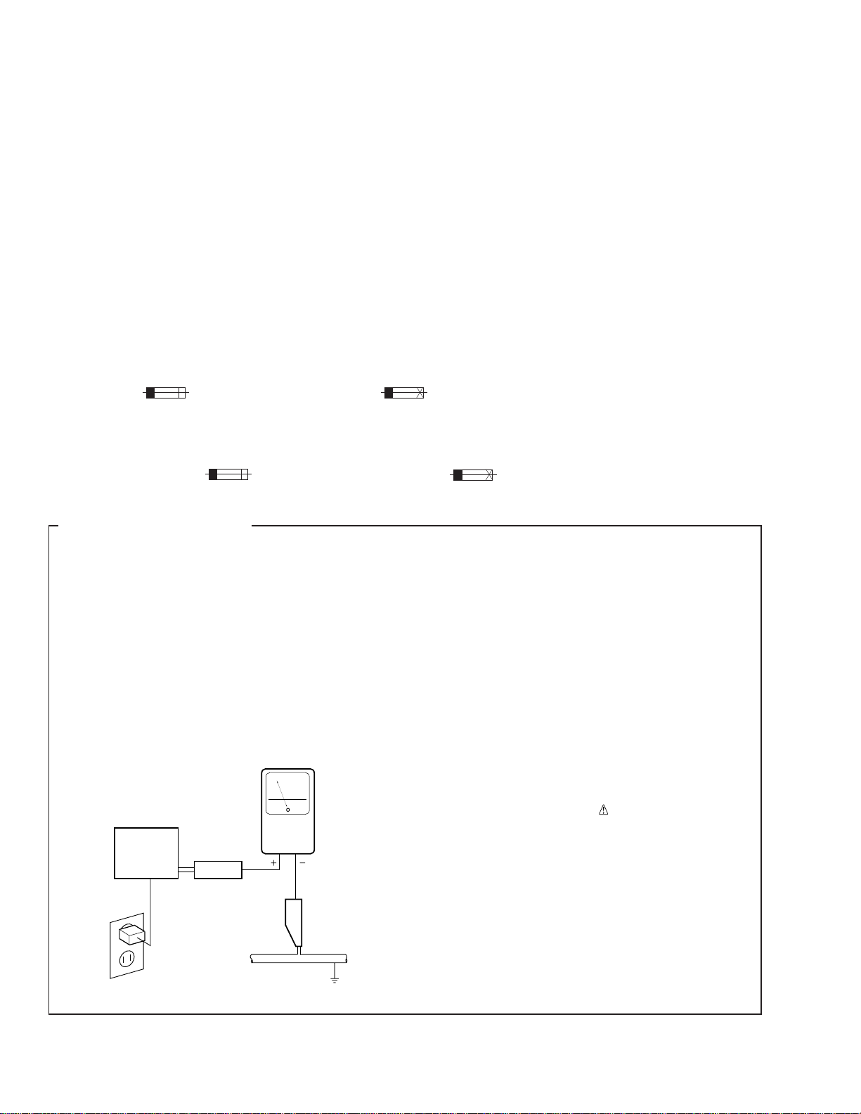
LEAKAGE CURRENT CHECK
Measure leakage current to a known earth ground
(water pipe, conduit, etc.) by connecting a leakage
current tester such as Simpson Model 229-2 or
equivalent between the earth ground and all exposed
metal parts of the appliance (input/output terminals,
screwheads, metal overlays, control shaft, etc.). Plug
the AC line cord of the appliance directly into a 120V
AC 60 Hz outlet and turn the AC power switch on. Any
current measured must not exceed 0.5 mA.
Reading should
not be above
0.5 mA
Earth
ground
Device
under
test
Also test with
plug reversed
(Using AC adapter
plug as required)
Test all
exposed metal
surfaces
AC Leakage Test
Leakage
current
tester
ANY MEASUREMENTS NOT WITHIN THE
LIMITS OUTLINED ABOVE ARE INDICATIVE
OF A POTENTIAL SHOCK HAZARD AND
MUST BE CORRECTED BEFORE RETURNING THE APPLIANCE TO THE CUSTOMER.
2. PRODUCT SAFETY NOTICE
Many electrical and mechanical parts in the appliance
have special safety related characteristics. These are
often not evident from visual inspection nor the
protection afforded by them necessarily can be obtained
by using replacement components rated for voltage,
wattage, etc. Replacement parts which have these
special safety characteristics are identified in this
Service Manual.
Electrical components having such features are
identified by marking with a
on the parts list in this Service Manual.
The use of a substitute replacement component which
does not have the same safety characteristics as the
PIONEER recommended replacement one, shown in the
parts list in this Service Manual, may create shock, fire,
or other hazards.
Product Safety is continuously under review and new
instructions are issued from time to time. For the latest
information, always consult the current PIONEER
Service Manual. A subscription to, or additional copies
of, PIONEER Service Manual may be obtained at a
nominal charge from PIONEER.
on the schematics and
2
2. EXPLODED VIEWS AND PARTS LIST
NOTES : ÷ Parts marked by “ NSP ” are generally unavailable because they are not in our Master Spare Parts List.
÷ The
÷ Screw adjacent to ∞ mark on the product are used for disassembly.
mark found on some component parts indicates the importance of the safety factor of the part.
Therefore, when replacing, be sure to use parts of identical designation.
S-W100S
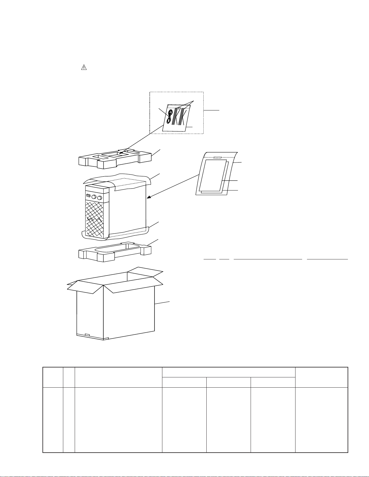
2.1 PACKING
10
7
5
9
2
9
4
6
3
4
8
(1) PACKING PARTS LIST
Mark No. Description Parts No.
1 Packing Case See Contrast table (2)
2 Top Protector SHA2126
NSP 3 Warranty Card See Contrast table (2)
4 Sheet (550X300X0.5) SHC1721
NSP 5 Cord Set SME2789
1
NSP 9 Polyethylene Bag E11- 024
6 Operating instructions See Contrast table (2)
7 Speaker cords (L=3.0m) SDS1052
8 Bottom Protector SHA2127
10 RCA Plug cord (L=3.0m) SDE1028
(2) CONTRAST TABLE
S-W100S/MYXMA, MLXMA/E and SDXMA1/E are constructed the same except for the following:
No.
1 Packing Case SHG2108 SHG2110 SHG2109
NSP 3 Warranty Card ARY7022 Not used Not used
6 Operating instructions SRD1200 Not used Not used
Dutch/ Swedish/ Spanish/ Portuguese)
6 Operating instructions Not used SRD1202 Not used
6 Operating instructions Not used Not used SRD1201
(English/ Chinese/Spanish/ Portuguese)
Symbol and Description
MYXMA type MLXMA/E type SDXMA1/ E type
(English/ French/ German/ ltalian/
(English/ Chinese)
Part No.
RemarksMark
3
S-W100S
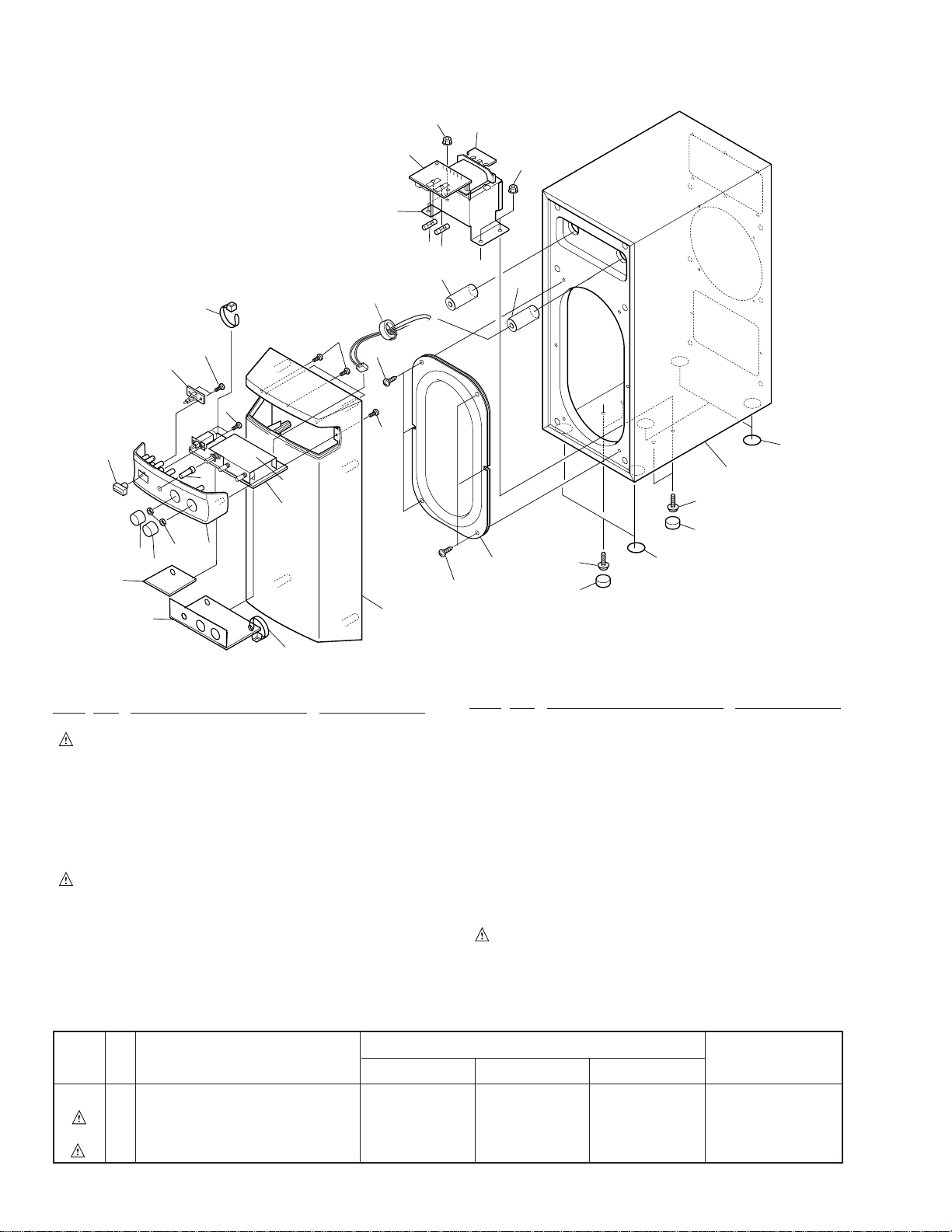
2.2 EXTERIOR (FRONT)
25
27
10
11
28
14
22
14
2
8
8
13
12
13
15
4
5
12
3
15
4
23
18
26
17
24
20
13
7
13
21
19
16
9
6
25
(1) EXTERIOR (FRONT) SECTION PARTS LIST
Mark No. Description Parts No.
NSP 1 CS ASSY See Contrast table (2)
2 Fuse (T1.6A/250V: FU 1) SEK1005
3 Grill SMG1616
4 Cap SEC1396
5 Passive Radiator SWP9002
6 CONT ASSY SWZ1009
7 LED ASSY SWZ1015
8 Packing SEC1407
NSP 9 Shielding Plate SNE1024
10 Power Transformer See Contrast table (2)
11 TRN. PRI ASSY See Contrast table (2)
12 Screw BYC40P160FZB
13 Screw BPZ30P100FZK
14 Nut KBA1047
15 Screw KBA1048
Mark No. Description Parts No.
16 Front Panel Assy SXB1344
17 VR Knob SNK2333
18 Power button SNK2335
19 Phase button(0°/180°) SNK2336
20 Turnover Knob SNK2334
21 Nut NK70FUC
22 TRN. SEC ASSY SWZ1014
23 Nonskid Pad SEC1397
NSP 24 Shielding Sheet SES1020
25 Binder SEP- 135
26 Barrier SEC1422
27 Ferrite Core SMF1001
28 Fuse (T1.6A/250V: FU 2) See Contrast table (2)
(2) CONTRAST TABLE
S-W100S/MYXMA, MLXMA/E and SDXMA1/E are constructed the same except for the following:
No.
Symbol and Description
MYXMA type MLXMA/E type SDXMA1/ E type
Part No.
23
1
RemarksMark
NSP 1 CS ASSY SMW1546 SMW1548 SMW1547
10 Power Transformer (AC220-230V) STT1007 STT1008 STT1009
11 TRN. PRI ASSY SWZ1012 SWZ1012 SWZ1013
28 Fuse (T1.6A/250V: FU 2) Not used Not used SEK1005
4
 Loading...