

Page 1
SOUND & VISION MIXER
TABLE DE MIXAGE SON ET VIDÉO
SOUND & VISION-MISCHPULT
MIXER AUDIO E VIDEO
MENGPANEEL VOOR GELUID & BEELD
CONSOLA DE MEZCLA DE SONIDO Y VISIÓN
АУДИО И ВИДЕО МИКШЕР
SVM-1000
Operating Instructions
Mode d’emploi
Bedienungsanleitung
Istruzioni per l’uso
Handleiding
Manual de instrucciones
Page 2
Thank you for buying this Pioneer product.
Please read through these operating instructions so you will know how to operate your model properly. After you have finished
reading the instructions, put them away in a safe place for future reference.
In some countries or regions, the shape of the power plug and power outlet may sometimes differ from that shown in the
explanatory drawings. However the method of connecting and operating the unit is the same.
If the AC plug of this unit does not match the AC
IMPORTANT
CAUTION
RISK OF ELECTRIC SHOCK
DO NOT OPEN
The lightning flash with arrowhead symbol,
within an equilateral triangle, is intended to
alert the user to the presence of uninsulated
"dangerous voltage" within the product's
enclosure that may be of sufficient
magnitude to constitute a risk of electric
shock to persons.
Replacement and mounting of an AC plug on the power supply cord of this unit should be performed only by qualified
service personnel.
IMPORTANT: THE MOULDED PLUG
This appliance is supplied with a moulded three pin mains plug for your safety and convenience. A 10 amp fuse is fitted in this plug. Should the
fuse need to be replaced, please ensure that the replacement fuse has a rating of 10 amps and that it is approved by ASTA or BSI to BS1362.
Check for the ASTA mark or the BSI mark on the body of the fuse.
If the plug contains a removable fuse cover, you must ensure that it is refitted when the fuse is replaced. If you lose the fuse cover the plug
must not be used until a replacement cover is obtained. A replacement fuse cover can be obtained from your local dealer.
If the fitted moulded plug is unsuitable for your socket outlet, then the fuse shall be removed and the plug cut off and disposed of
safely. There is a danger of severe electrical shock if the cut off plug is inserted into any 13 amp socket.
If a new plug is to be fitted, please observe the wiring code as shown below. If in any doubt, please consult a qualified electrician.
IMPORTANT: The wires in this mains lead are coloured in accordance with the following code:
Blue : Neutral Brown : Live
As the colours of the wires in the mains lead of this appliance may not correspond with the coloured markings identifying the terminals in
your plug, proceed as follows ;
The wire which is coloured BLUE must be connected to the terminal which is marked with the
letter N or coloured BLACK.
The wire which is coloured BROWN must be connected to the terminal which is marked with the
letter L or coloured RED.
How to replace the fuse: Open the fuse compartment with a screwdriver and replace the fuse.
Operating Environment
Operating environment temperature and humidity:
+5 ºC – +35 ºC (+41 ºF – +95 ºF); less than 85 %RH
(cooling vents not blocked)
Do not install this unit in a poorly ventilated area, or in
locations exposed to high humidity or direct sunlight (or
strong artificial light)
WARNING
CAUTION:
TO PREVENT THE RISK OF ELECTRIC
SHOCK, DO NOT REMOVE COVER (OR
BACK). NO USER-SERVICEABLE PARTS
INSIDE. REFER SERVICING TO QUALIFIED
SERVICE PERSONNEL.
WARNING
Before plugging in for the first time, read the following
section carefully.
The voltage of the available power supply differs
according to country or region. Be sure that the
D3-4-2-1-7c_A_En
power supply voltage of the area where this unit
will be used meets the required voltage (e.g., 230 V
or 120 V) written on the rear panel.
To prevent a fire hazard, do not place any naked
flame sources (such as a lighted candle) on the
equipment.
If you want to dispose this product, do not mix it with general household waste. There is a separate collection system for used
electronic products in accordance with legislation that requires proper treatment, recovery and recycling.
Private households in the member states of the EU, in Switzerland and Norway may return their used electronic products free of charge to
designated collection facilities or to a retailer (if you purchase a similar new one).
For countries not mentioned above, please contact your local authorities for the correct method of disposal.
By doing so you will ensure that your disposed product undergoes the necessary treatment, recovery and recycling and thus prevent potential
negative effects on the environment and human health.
D3-4-2-1-7a_A_En
The exclamation point within an equilateral
triangle is intended to alert the user to the
presence of important operating and
maintenance (servicing) instructions in the
literature accompanying the appliance.
D3-4-2-1-1_En-A
D3-4-2-1-2-2_B_En
D3-4-2-1-4_A_En
K058_A_En
outlet you want to use, the plug must be removed
and appropriate one fitted. Replacement and
mounting of an AC plug on the power supply cord of
this unit should be performed only by qualified
service personnel. If connected to an AC outlet, the
cut-off plug can cause severe electrical shock. Make
sure it is properly disposed of after removal.
The equipment should be disconnected by removing
the mains plug from the wall socket when left
unused for a long period of time (for example, when
on vacation).
D3-4-2-2-1a_A_En
CAUTION
The POWER switch on this unit will not completely
shut off all power from the AC outlet. Since the
power cord serves as the main disconnect device for
the unit, you will need to unplug it from the AC outlet
to shut down all power. Therefore, make sure the
unit has been installed so that the power cord can
be easily unplugged from the AC outlet in case of an
accident. To avoid fire hazard, the power cord should
also be unplugged from the AC outlet when left
unused for a long period of time (for example, when
on vacation).
D3-4-2-2-2a_A_En
WARNING
This equipment is not waterproof. To prevent a fire
or shock hazard, do not place any container filled
with liquid near this equipment (such as a vase or
flower pot) or expose it to dripping, splashing, rain
or moisture.
D3-4-2-1-3_B_En
VENTILATION CAUTION
When installing this unit, make sure to leave space
around the unit for ventilation to improve heat
radiation (at least 5 cm at rear, and 3 cm at each
side).
WARNING
Slots and openings in the cabinet are provided for
ventilation to ensure reliable operation of the
product, and to protect it from overheating. To
prevent fire hazard, the openings should never be
blocked or covered with items (such as newspapers,
table-cloths, curtains) or by operating the
equipment on thick carpet or a bed.
D3-4-2-1-7b_A_En
This product complies with the Low Voltage Directive
2006/95/EC and EMC Directive 2004/108/EC.
D3-4-2-1-9a_A_En
POWER-CORD CAUTION
Handle the power cord by the plug. Do not pull out the
plug by tugging the cord and never touch the power
cord when your hands are wet as this could cause a
short circuit or electric shock. Do not place the unit, a
piece of furniture, etc., on the power cord, or pinch the
cord. Never make a knot in the cord or tie it with other
cords. The power cords should be routed such that they
are not likely to be stepped on. A damaged power cord
can cause a fire or give you an electrical shock. Check
the power cord once in a while. When you find it
damaged, ask your nearest PIONEER authorized
service center or your dealer for a replacement.
S002_En
Page 3
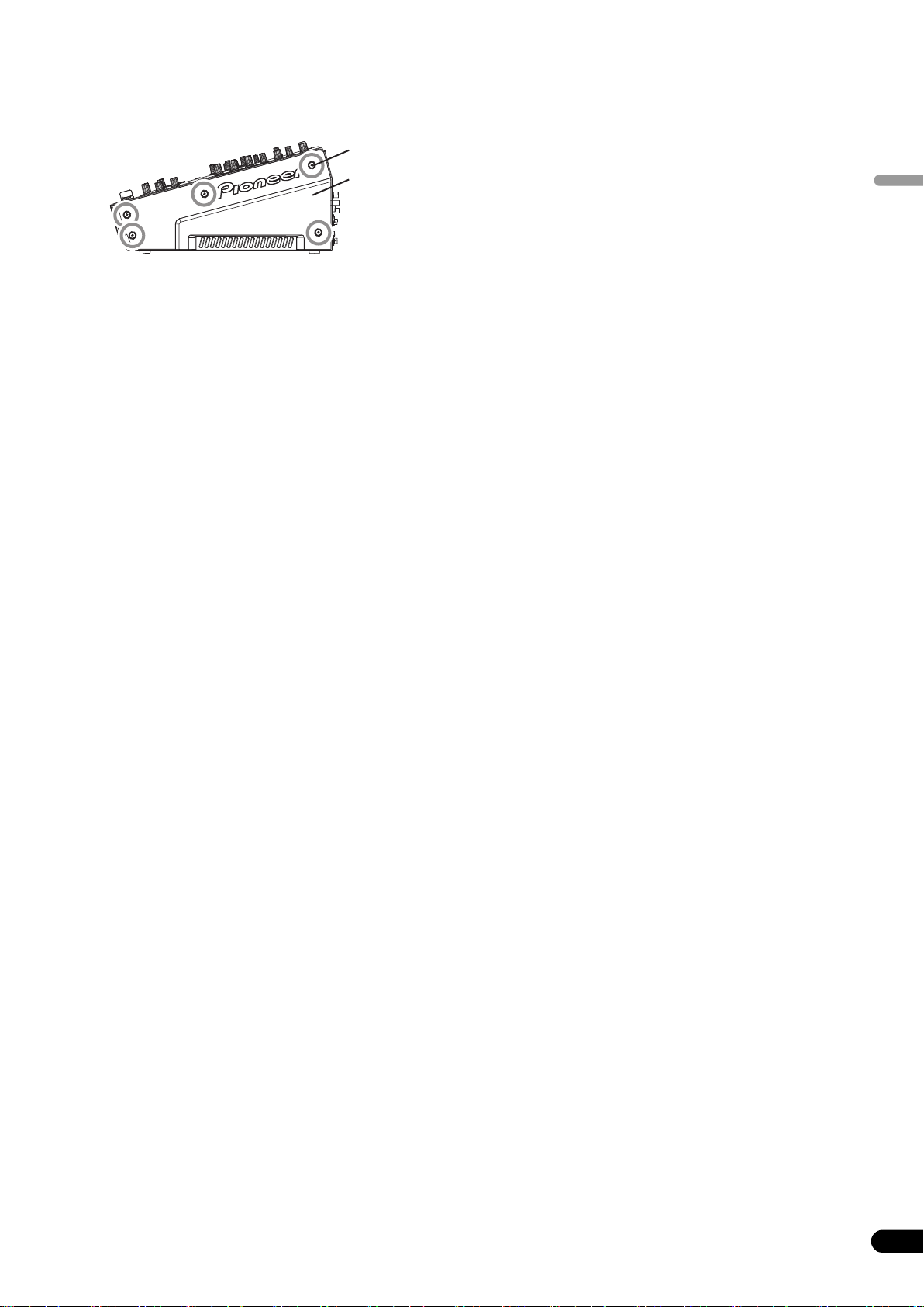
Installing the SVM-1000 in an EIA rack
The screw holes located on the left and right ends of the front
panel (within the side cover) match the 19-inch EIA rack.
• Remove the 10 screws (five screws each located on the left and
right sides of the unit) before installing the unit to the rack.
Screws
Side cover
• Holes for rack installation can be located when the side covers
are removed.
• Attach the unit to the rack using screws of the appropriate size
(screws not provided with the unit).
• When installing the unit in a rack, take care to avoid pinching
your fingers.
Contents
Note
• Never place this unit directly above a power amplifier, as the
heat given off by the amplifier might result in damage to the unit.
Placing the unit directly above a power amplifier might also
result in ham radio signals being picked up or in other types of
interference.
• Allow at least 1U (43.7 mm) space between this component and
the one mounted above it, so as to assure that the cords
connected to this unit's input/output connectors and terminals
do not touch the component above.
• Always be sure to remove the unit from its rack before shipping.
• When moving the unit while still installed in its rack, exercise
caution to avoid subjecting the unit to shocks or vibration.
English
CONFIRM ACCESSORIES..............................................4
CAUTIONS REGARDING HANDLING............................4
Location.......................................................................................... 4
Cleaning the Unit........................................................................... 4
Disclaimer ...................................................................................... 4
About Copyright............................................................................. 4
FEATURES ....................................................................4
NAMES AND FUNCTIONS OF PARTS ...........................6
CONNECTION PANEL ................................................................... 6
OPERATION PANEL ...................................................................... 7
CONNECTIONS...........................................................10
CONNECTING INPUTS ................................................................ 10
CONNECTING OUTPUTS ............................................................ 11
CONNECTING MICROPHONE AND HEADPHONES ............... 12
CONNECTING THE POWER CORD............................................ 12
BASIC OPERATIONS...................................................13
FADER CURVE SELECTION ....................................................... 14
USING THE VIDEO CONTROL FUNCTIONS .................15
OPERATING THE VIDEO CROSS FADER .................................. 15
OPERATING THE VIDEO CHANNEL SWITCH ........................... 15
OPERATING IN THE VIDEO SOLO MODE ................................. 16
VIDEO MIX EFFECTS CHART ...................................................... 16
USING THE EFFECT FUNCTION...................................17
USING BEAT EFFECTS ................................................................ 17
USING TOUCH EFFECTS............................................................. 19
USING TEXT EFFECTS ................................................................. 20
EDITING TEXT............................................................................... 22
DISPLAYING/HIDING THE MASTER MONITOR ........................ 22
EFFECT LIST.................................................................................. 23
USING THE JPEG VIEWER..........................................31
BEFORE USING THE JPEG VIEWER...........................................31
JPEG VIEWER SETUP .................................................................. 31
THE VIDEO EQUALIZER FUNCTION............................34
SET UP THE VIDEO EQ................................................................34
TURNING THE EQUALIZER ON/OFF ..........................................34
FADER START FUNCTION ..........................................35
CROSS FADER START PLAY AND BACK CUE PLAY................35
PERFORM UTILITY SETUP ..........................................36
MIDI SETTINGS ............................................................................36
SYNCHRONIZING AUDIO SIGNALS TO EXTERNAL
SEQUENCER, OR USING SVM-1000 INFORMATION TO
OPERATE AN EXTERNAL SEQUENCER ....................................36
MIDI CODE LIST ........................................................................... 37
PERFORM VIDEO MONITOR SETUP .........................................41
KEYBOARD LANGUAGE SETUP................................................. 41
HARDWARE SETUP....................................................42
MIC SETTING ................................................................................ 42
SYSTEM SETTINGS.......................................................................42
MASTER OUT SETTINGS .............................................................43
LCD SETTINGS..............................................................................43
MONITOR OUT SETTINGS...........................................................43
TOUCH PANEL SETTINGS........................................................... 44
RETURNING TO DEFAULT SETTINGS ........................................44
ENDING HARDWARE SET UP.................................................... 44
TROUBLESHOOTING ..................................................45
ABOUT THE LCD SCREEN ..........................................................46
ABOUT MINIATURE FLUORESCENT TUBE TECHNOLOGY .....46
SPECIFICATIONS........................................................47
En
3
Page 4

CONFIRM ACCESSORIES / CAUTIONS REGARDING HANDLING / FEATURES
CONFIRM
ACCESSORIES
Power cord . . . . . . . . . . . . . . . . . . . . . . . . . . . . . . . . . . . . . . . . . . . . . .1
Warranty card . . . . . . . . . . . . . . . . . . . . . . . . . . . . . . . . . . . . . . . . . . . .1
Operating Instructions. . . . . . . . . . . . . . . . . . . . . . . . . . . . . . . . . . . . .1
FEATURES
4-Channnel Music and Video Synchromix
Most conventional image mixing devices are limited to the simple
mixing of two video images, but Pioneer’s own uniquely developed
video blending technology makes it possible to simultaneously mix
up to four channels of music and video. Since the synchro control
allows the use of fader and equalizers with each channel, a new,
wider range of performances is possible with the sensation of
using conventional DJ mixers.
“AV Effects” support a wide variety of new
CAUTIONS REGARDING
performance styles by synchronizing music and
video.
HANDLING
Location
Install the unit in a well-ventilated location where it will
not be exposed to high temperatures or humidity.
• Do not install the unit in a location which is exposed to direct
rays of the sun, or near stoves or radiators. Excessive heat
can adversely affect the cabinet and internal components.
Installation of the unit in a damp or dusty environment may
also result in a malfunction or accident. (Avoid installation
near cookers etc., where the unit may be exposed to oily
smoke, steam or heat.)
• When the unit is used inside a carrying case or DJ booth,
separate it from the walls or other equipment to improve heat
radiation.
Cleaning the Unit
• Use a polishing cloth to wipe off dust and dirt.
• When the surfaces are very dirty, wipe with a soft cloth
dipped in some neutral cleanser diluted five or six times with
water and wrung out well, then wipe again with a dry cloth.
Do not use furniture wax or cleaners.
• Never use thinners, benzene, insecticide sprays or other
chemicals on or near this unit, since these will corrode the
surfaces.
Disclaimer
• Microsoft and Windows are registered trademarks of
Microsoft Corporation, registered in the U.S. and other
countries.
Apple and Mac OS are trademarks of Apple Inc., registered
in the U.S. and other countries.
• The typefaces included herein are partially developed by
DynaComware Taiwan Inc.
About Copyright
This product incorporates copyright protection technology that is
protected by U.S. patents and other intellectual property rights.
Use of this copyright protection technology must be authorized by
Macrovision Corporation, and is intended for home and other
limited consumer uses only unless otherwise authorized by
Macrovision. Reverse engineering or disassembly is prohibited.
Equipped with AV Effects that synchronize music effects and video
effects on the large 11-inch LCD touch panel display, allowing up
to 30 types of effects to be applied to your music and images.
1 Beat effect: Automatically detects the tempo of the currently
2 Touch effect: By directly touching the image displayed on the
3 Text effect: Text messages created in synchronization with the
“JPEG VIEWER” allows use of images stored in
external memory for live performances
Up to eight JPEG files saved on SD memory cards or USB memory
devices can be downloaded and used as a still image sampler. By
applying effects or mixing with other videos and images such as
the name of the DJ or event, or graphic logos, you can broaden the
potential of your performance. Additionally, JPEG files can be
loaded and displayed as an automatic slide show.
Digital sound/video system for high quality sound
and image
1 96 kHz/24-bit sampling digital system for high sound quality
Analog signals input from a DJ player are passed through the
shortest possible signal path and digitized using a high-fidelity A/D
converter with 96 kHz/24-bit sampling, producing optimum quality
for digital mixing. Mixing is performed by a 32-bit DSP to eliminate
any degradation in sound quality, while simultaneously using ideal
filtering to produce optimum sound for DJ play.
In order to realize the greatest possible response, the unit also
features a high-rigidity chassis and double-shield construction to
suppress unwanted vibrations that might adversely effect sound
quality, together with a powerful power section and other highfidelity technology, thus producing clear, powerful club sounds.
2 High-performance video IC digital system for high image
Video signals input through the high-performance ADC are
processed through a high-performance video DSP rated at 600
MHz/32-bit/4800 MIPS (Million Instructions Per Second), thus
preserving the original image’s dynamic range while also
suppressing unwanted noise and producing images with high
fidelity and quality. The same high quality has also been realized
for video effects that normally tend to be a source of image
degradation.
playing track, and applies effects to music and image in synch
with the beat.
large LCD touch panel, effects can be applied to music and
video more intuitively.
automatically detected track tempo can be displayed with
effects. Text messages can be entered either by the built-in
keyboard or a common USB keyboard.
quality
In the event that the above noted copy protection function operates
in any channel, some effects (DELAY, ECHO, ROLL, REVERSE
ROLL) will not function.
4
En
Page 5

FEATURES
Improved design and operability for new club
culture
Based on the concept of creating “a design that fascinates,” the
boxy-shape of previous DJ mixers has been restyled toward an
edgier and more solid design. Great attention has been given to
details of materials and design, such as employing an
“illumination display” on the rear panel visible from the dance
floor.
Operating panel design emphasizes convenience for
simultaneous performances of music and video, with a “channel
symmetry layout” centered around the 11-inch LCD touch panel.
By arranging each channel section symmetrically, further
improvements in operabilit y hav e bee n mad e to a ssist easy mixing
between music and video, so that effects can be enabled
dynamically from the LCD touch panel.
Other DJ/VJ performance functions made possible
through digital technology
1 “VIDEO TRIM” allows adjustment of the luminance of images
input to each channel.
2 “VIDEO EQUALIZER” assigns parameters such as [RGB],
[CONTRAST], [HUE], and [SATURATION] to the equalizer,
allowing synchronization of audio equalizing and video
controls.
3 “AV SYNC” allows the user to select whether audio and video
controls are linked or adjusted separately.
4 “VIDEO MONITOR SELECTOR” allows the user to choose
whether the monitor video output shows master only, all
channels, master and each channel, master mixing inversion,
etc.
5 “FULLY ASSIGNABLE MIDI” allows control of DJ effecter, DJ/
VJ application programs, and other external components.
English
En
5
Page 6
NAMES AND FUNCTIONS OF PARTS
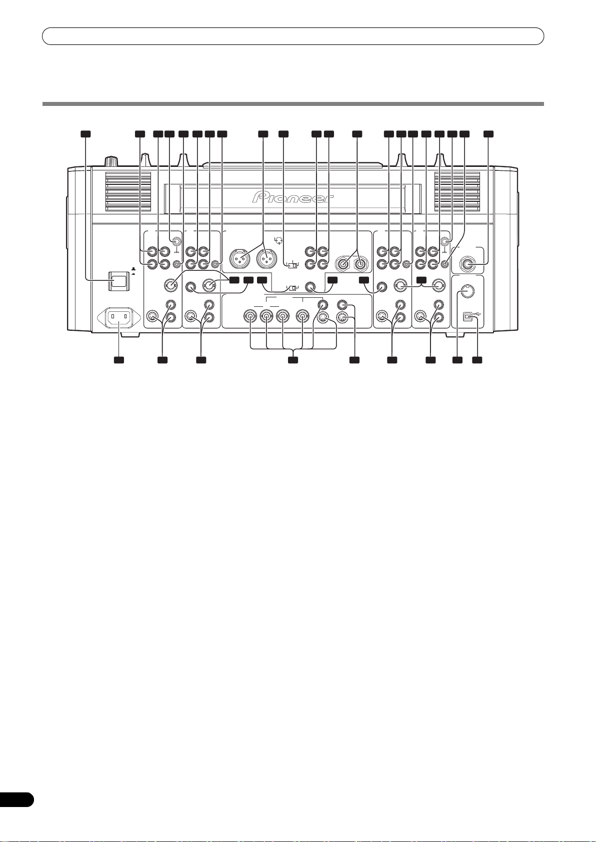
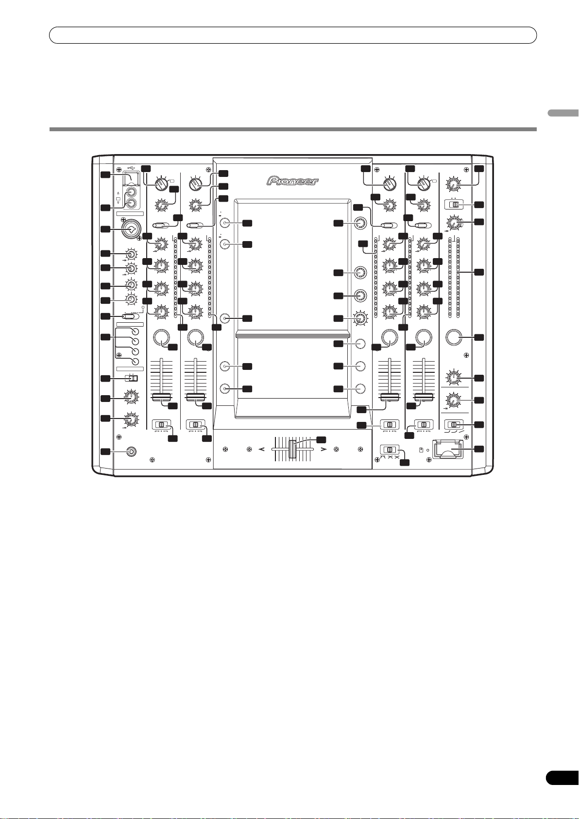
NAMES AND FUNCTIONS OF PARTS
CONNECTION PANEL
1
2 3 4 95 6 7 10 11
POWER
AC IN
4 3
PHONO
L
R
OFF
ON
S-VIDEO
SIGNAL GND
DVD/LINE LINE
L
CONTROL
R
SYNC
DIGITAL
OUT
IN
DVD
S-VIDEO
VIDEO
AUDIO OUT
DVD
CONTROL
SYNC
OUT
14 15 16 17 15 14
DVD
VIDEO OUT
VIDEO
8 12
1 GND 2 HOT
MASTER OUT 1
R
L
COMPONENT COMPOSITE
YC
B CR
3 COLD
18 19 19 19 1921 232220
1 POWER switch
2 PHONO input connectors
RCA type phono level (MM cartridge) input connectors.
Do not use for inputting line level signals.
3 DVD/LINE input connectors
RCA type line level audio input connectors.
Use to connect a DJ/VJ DVD player or DJ CD player or other line
level output component.
4 Signal ground terminal (SIGNAL GND)
Connect the ground wire from an analog turntable.
This is not a safety ground terminal.
5 CONTROL connector
Connect the Ø 3.5 mm mini phone plug of the control cable from
a DJ/VJ DVD player or DJ CD player.
When this is done, this mixer’s fader controls can be used to
perform start and back-cue functions on the connected DJ/VJ DVD
player or DJ CD player.
6 LINE input connectors
RCA type line level audio input connectors.
Use to connect a cassette deck or other line level output
component.
7 DVD input connectors
RCA type line level audio input connectors.
Use to connect a DJ/VJ DVD player or DJ CD player or other line
level output component.
8 Audio master output 1 connectors (MASTER OUT 1)
XLR type (male) balanced output.
• When using a cord with RCA-type plug, users are recommended
to connect the plug directly to the MASTER OUT 2 connectors
without using an XLR/RCA converter plug.
When a conversion plug is used, the signal GND may become
unstable, in rare cases resulting in the production of noise.
9 Audio master output attenuator selector (MASTER ATT.)
Attenuates the output level of the audio master 1 and audio master
2.
Attenuation level can be selected as 0 dB, –3 dB, or –6 dB.
10 Audio master output 2 connectors (
MASTER OUT 2
)
RCA-type unbalanced output.
2 3 4 555 6 7 13
-6 dB 0 dB
48 k 96 k
MASTER
MASTER
ATT.
-3 dB
DIGITAL OUT
fs (Hz)
L
R
MASTER
OUT 2
REC
OUT
MONITOR
S-VIDEO S-VIDEO
BOOTH
MONITOR
(TRS)
21
LINE
DVD PHONO
L
LR
R
DIGITAL
IN
S-VIDEO
CONTROL
SYNC
OUT
DVD
VIDEO
L
R
S-VIDEO
SIGNAL GND
DVD/LINE
CONTROL
SYNC
OUT
DVD
VIDEO
MIC2
MIDI
OUT
USB
11 Recording output connectors (REC OUT)
RCA type output connectors for recording.
12 BOOTH MONITOR output jacks (TRS)
Ø 6.3 mm phone-type booth monitor output jacks.
The sound level output at these connectors can be controlled by
the BOOTH MONITOR level dial, regardless of the setting of the
MASTER LEVEL dial. (Since the output is TRS, both balanced and
unbalanced outputs are supported.)
13 Microphone 2 input jack (MIC 2)
Connect microphones equipped with phone-type plug.
14 Sync signal output connector (SYNC OUT)
Outputs video sync signal.
When connecting a Pioneer DJ/VJ DVD player (sold separately),
the sync signal helps suppress any lag between video and audio
signals.
15 Digital input connector (DIGITAL IN)
RCA-type digital coaxial input connector. Connect to the digital
coaxial output connector from a DJ/VJ DVD player or DJ CD player.
• If the sampling frequency of the output signal changes, the
sound may be interrupted briefly.
16 Sampling frequency selector switch (fs 48 k/96 k)
Use to set the sampling frequency of the digital output to 96 kHz/
24-bit format or 48 kHz/24-bit format.
Turn power off before changing this switch position.
17 Digital output connector (DIGITAL OUT)
RCA type digital coaxial output connector.
Master audio digital output.
18 Power inlet (AC IN)
Use the furnished power cable to connect to a household AC
outlet.
19 Video input connectors (DVD, VIDEO, S-VIDEO)
Composite and S-VIDEO type video input connectors.
20 Video master output connectors
(MASTER: COMPONENT, COMPOSITE, S-VIDEO)
Component, composite, and S-VIDEO type video output
connectors.
21 Video monitor output connectors (MONITOR, S-VIDEO)
Composite and S-VIDEO type monitor video output connectors.
6
En
Page 7
NAMES AND FUNCTIONS OF PARTS
22 MIDI OUT connector
DIN type output connector.
Use to connect to other MIDI component.
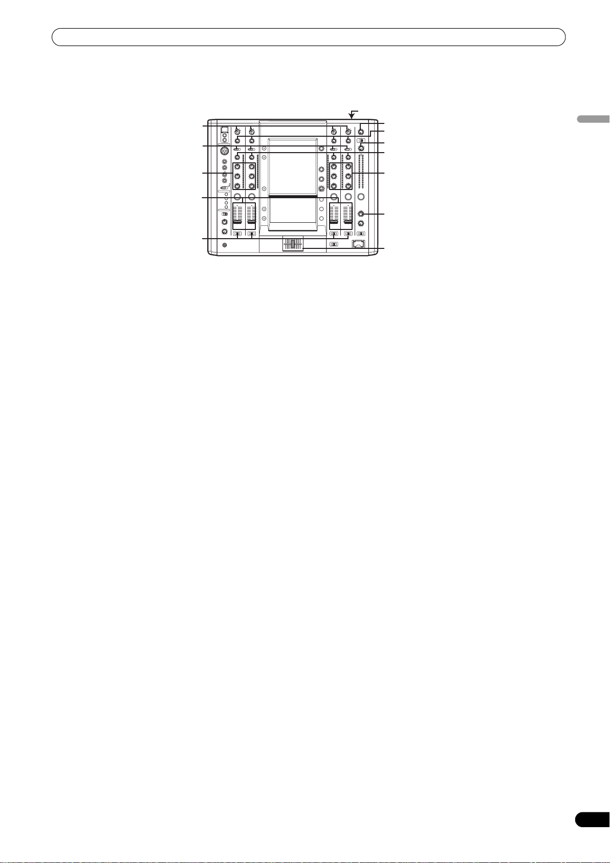
OPERATION PANEL
1
2
3
4
5
6
7
8
9
10
11
12
13
VIDEO INPUT
14 16 17 32
VIDEO
MIC
23 23
0
24 24
0
25 25
+12
26
+12
TALK
OVER
CH1
CH2
CH3
CH4
MIXING
MASTER
LEVEL
0
PHONES
DVD
VIDEO TRIM
MIN
AUDIO INPUT
DVD/LINE PHONO
AUDIO TRIM
LOW
CUE
1
CROSS FADER
ASSIGN
A THRU B
PROFESSIONAL SOUND
USB
CH 1
VIDEO
EX
CH 4
MIC 1
MIC1
LEVEL
MIC2
LEVEL
HI
-12
LOW
-12
MIC OFF ON
FADER START
HEAD PHONES
MONO SPLIT STEREO
CUE
VIDEO INPUT
DVD
S-VIDEO
VIDEO
EX
18
VIDEO TRIM
MAX
MIN
AUDIO INPUT
19 22
DVD LINE DIGITAL
AUDIO TRIM
OVER
10
+9
7
HI
4
2
1
0
+6-26
–1
MID
–2
–3
–5
+6-26
–7
26
–10
–15
–24
+6-26
dB
28
2
10
9
8
7
6
5
4
3
2
1
0
29
CROSS FADER
ASSIGN
A THRU B
30
&
VISION MIXER
SVM-1000
23 MIDI USB output connector
USB-B type output connector. Use to connect to a computer.
English
VIDEO INPUT
VIDEO
HI
MID
LOW
S-VIDEO
MAX
+9
+6-26
+6-26
+6-26
23
24
25
26
OVER
dB
DVD
VIDEO TRIM
MIN
AUDIO INPUT
LINE PHONO
AUDIO TRIM
10
7
4
2
1
0
–1
–2
–3
–5
–7
–10
–15
–24
VIDEO
LOW
27
CUE
CUE
28
3
10
9
8
7
6
5
4
3
2
1
0
29
CROSS FADER
ASSIGN
A THRU B
30
18 18
21
CH SELECT
DVD LINE DIGITAL
OVER
27
10
7
4
VIDEO FX
PATTERN/
2
TEXT BANK
1
0
–1
–2
TIME/
–3
–5
–7
–10
LEVEL/
–15
DEPTH
–24
dB
MAXMIN
EFFECT
CUE
28
10
9
8
7
6
EFFECT
5
ON/OFF
4
3
2
1
0
29
30
CROSS FADER CURVE SD CARD
VIDEO INPUT
DVD
VIDEO TRIM
MIN
AUDIO INPUT
AUDIO TRIM
CROSS FADER
ASSIGN
A THRU B
VIDEO
S-VIDEO
15
18
20
UTILITY
MASTER
MAX
MONITOR
SET UP
40
VIDEO EQ
OVER
ON/OFF
SET UP
10
+9
7
HI
4
2
1
0
+6-26
–1
MID
–2
–3
–5
+6-26
–7
LOW
–10
–15
–24
+6-26
dB
JPEG
VIEWER
41
42
45
46
PARAMETER
47
48
2727
CUE
28
VIDEO
SOLO MODE
10
9
8
7
6
5
4
3
2
1
0
FADER
AV SYNC
43
44
28
49
50
29
30
51
AB
31
HI
MID
S-VIDEO
MAX
+9
+6-26
+6-26
+6-26
4
VIDEO
EX
23
24
25
26
VIDEO
MASTER LEVEL
WHITEBLACK
MONO STEREO
AUDIO MASTER LEVEL
0
OVER
10
7
4
2
1
0
–1
–2
–3
–5
–7
–10
–15
–24
dBLR
CUE
MASTER
BALANCE
RL
BOOTH MONITOR
0
CH FADER CURVE
33
34
35
28
36
37
38
39
1 USB connector
Use to connect a USB memory or keyboard.
2 CH1/CH4 video input connectors (VIDEO EX)
Use to input video from an external source.
3 Microphone 1 input jack (MIC 1)
Connect microphone with XLR-type or phone-type plug.
4 Microphone 1 level control dial (MIC 1 LEVEL)
Use to adjust the volume of microphone 1. (Adjustable range –∞ to
0dB)
5 Microphone 2 level control dial (MIC 2 LEVEL)
Use to adjust the volume of microphone 2. (Adjustable range –∞ to
0dB)
6 Microphone equalizer high-range adjust dial (HI)
Use to adjust the treble (high-range) frequencies of microphones 1
and 2. (Adjustable range –12 dB to +12 dB)
7 Microphone equalizer low-range adjust dial (LOW)
Use to adjust the bass (low-range) frequencies of microphones 1
and 2. (Adjustable range –12 dB to +12 dB)
8 Microphone function selector switch (MIC)
OFF:
No microphone sound is output.
ON:
Microphone sounds are output, and the microphone function
indicator lights.
TALK OVER:
Microphone sounds are output, and the microphone function
indicator flashes.
When an audio signal of –15 dB or more (default setting) is input
to the microphone input, the talkover function operates to reduce
all output other than the mike audio by 20 dB (default setting).
Values can be changed in the hardware setup (P. 42)
• When not using the TALK OVER function, it is recommended to
set the switch to the [OFF] or [ON] position.
9 FADER START button/indicator (CH-1 to CH-4)
Enables the fader start/back cue function for the channel to which
a DJ/VJ DVD player or DJ CD player is connected. The button lights
when set to ON. When enabled, the operation differs depending on
the setting of the CROSS FADER ASSIGN switch.
•When the CROSS FADER ASSIGN switch is set to the [A] or [B]
position, FADER START button operation is linked to the
operation of the cross fader (and unlinked to channel fader).
•When the CROSS FADER ASSIGN switch is set to the [THRU]
position, FADER START button operation is linked to the
operation of the channel fader (and unlinked to cross fader).
En
7
Page 8

NAMES AND FUNCTIONS OF PARTS
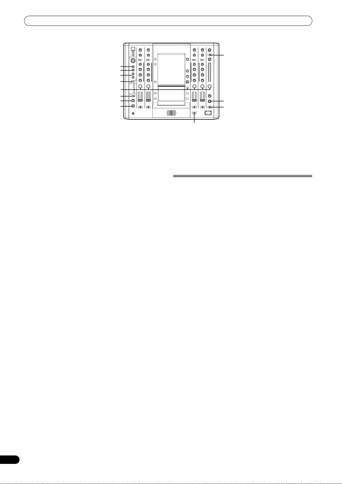
10 HEADPHONES output switch (MONO SPLIT/STEREO)
MONO SPLIT:
The source sound selected with the headphone CUE button is
output to the L channel, while the master sound is output to the R
channel (only when [MASTER] is selected with the headphone
CUE button).
STEREO:
The audio source selected with the headphone CUE button is
output in stereo.
11 HEADPHONES MIXING dial
When rotated clockwise (toward [MASTER]), the master output
audio is produced at the headphones (only when [MASTER] has
been selected with the headphone CUE button); when rotated
counterclockwise (toward [CUE]), the headphones output
becomes the mixture of the effect monitor and the channel
selected with the headphone CUE button.
12 HEADPHONES LEVEL adjust dial
Adjusts the output level of the headphones jack. (Adjustable
range: –∞ to 0 dB)
13 Headphones jack (PHONES)
14 Channel 1 VIDEO INPUT selector switch
Set to [DVD], [VIDEO], [S-VIDEO], or [VIDEO EX] to match the
type of input connected.
15 Channel 2 VIDEO INPUT selector switch
Set to [DVD], [VIDEO], or [S-VIDEO] to match the type of input
connected.
16 Channel 3 VIDEO INPUT selector switch
Set to [DVD], [VIDEO], or [S-VIDEO] to match the type of input
connected.
17 Channel 4 VIDEO INPUT selector switch
Set to [DVD], [VIDEO], [S-VIDEO], or [VIDEO EX] to match the
type of input connected.
18 VIDEO TRIM dial
Use to adjust the level of the video input signal for each channel.
• When rotated counterclockwise, the luminance level is reduced,
eventually producing a black screen.
• When rotated clockwise, the luminance level is raised,
eventually producing a white screen.
• At the center position, the luminance level is neutral (same level
as input).
19 Channel 1 AUDIO INPUT selector switch
DVD/LINE:
Use to select DVD/LINE input connectors (line level analog input).
PHONO:
Use to select
input).
20 Channel 2 AUDIO INPUT selector switch
DVD:
Use to select DVD input connectors.
LINE:
Use to select LINE input connectors (line level analog input).
DIGITAL:
Use to select DIGITAL input connector.
21 Channel 3 AUDIO INPUT selector switch
DVD:
Use to select DVD input connectors.
LINE:
Use to select LINE input connectors (line level analog input).
DIGITAL:
Use to select DIGITAL input connector.
22 Channel 4 AUDIO INPUT selector switch
DVD/LINE:
Use to select DVD/LINE input connectors (line level analog input).
PHONO:
Use to select
input).
PHONO input connectors (PHONO level analog
PHONO input connectors (PHONO level analog
23 AUDIO TRIM dial
Use to adjust the level of the audio input signal for each channel.
(Adjustable range: –∞ to +9 dB, mid-position is about 0 dB)
24 Channel equalizer high-range adjust dial (HI)
Use to adjust the treble (high-range) frequency sound for each
channel. Video parameters can also be assigned. See P. 34
regarding video parameters. (Adjustable range: –26 dB to +6 dB)
25 Channel equalizer mid-range adjust dial (MID)
Use to adjust the mid-range frequency sound for each channel.
Video parameters can also be assigned. See P. 34 regarding video
parameters. (Adjustable range: –26 dB to +6 dB)
26 Channel equalizer low-range adjust dial (LOW)
Use to adjust the bass (low-range) frequency sound for each
channel. Video parameters can also be assigned. See P. 34
regarding video parameters. (Adjustable range: –26 dB to +6 dB)
27 Channel level indicator
Displays the current level for each channel, with two-second peak
hold.
28 Headphone
These buttons are used to select from 1 to 4, MASTER, or
EFFECT CUE, to allow you to monitor the desired source through
headphones. If multiple buttons are pressed simultaneously, the
selected audio sources are mixed. Press the button once more to
cancel the selected source. Unselected buttons glow darkly, while
selected source buttons light brightly.
29 Channel fader lever
Use to adjust sound volumes and video level for each channel.
(Volume adjust range: –∞ to 0 dB) (Video adjust range: 0 % to
100 %)
Output is in accordance with the channel fader curve selected with
the CH FADER CURVE switch.
When FADER AV SYNC function is OFF, only sound volume can be
adjusted.
30 CROSS FADER ASSIGN switch
This switch assigns each channel’s output to either right or left
side of the cross fader (if multiple channels are assigned to the
same side, the result will be the combined sum of the channels).
A:
The selected channel is assigned to the cross fader’s [A] (left) side.
THRU:
The channel fader’s output is sent as is to the master output,
without being passed through the cross fader.
B:
The selected channel is assigned to the cross fader’s [B] (right)
side.
31 CROSS FADER CURVE switch
This switch allows the user to select from three types of cross fader
curve response.
Sound volume changes as follows:
• At the left setting, the curve produces a rapid signal rise. (As
soon as the cross fader lever leaves the [A] side, the [B] channel
sound is produced.)
• At the right setting, the curve operates to produce an even,
neutral rise throughout the cross fader’s movement.
• At the middle setting, an intermediate curve is produced,
midway between the two curves noted above.
The video level is as noted above only when the video cross fader’s
video mix effect is set to [FADE].
32 Video master output level dial (VIDEO MASTER LEVEL)
Adjusts the video master output luminance level.
33 Master output MONO/STEREO selector switch
When set to the [MONO] position, audio master output is
produced in L+R monaural.
34 Audio master output level dial (AUDIO MASTER LEVEL)
Use to adjust the master output level. (Adjustable range: –∞ to
0dB)
The master output is the sum combination of the sound from
channels set to [THRU] with the CROSS FADER ASSIGN switch;
CUE
buttons/indicators
8
En
Page 9

NAMES AND FUNCTIONS OF PARTS
the signal passed through the cross fader; and the signals from
microphone 1 and microphone 2.
35 Master level indicator (MASTER L, R)
These segment indicators display the audio output level from L and
R channels. The indicators have a two-second peak hold.
36 Master balance dial (BALANCE)
Use to adjust the L/R channel balance for audio master output,
booth monitor output, recording output, and digital output.
37 BOOTH MONITOR level control dial
This dial is used to adjust the booth monitor output volume.
The volume can be adjusted independently of the master output
level. (Adjustable range: –∞ to 0 dB)
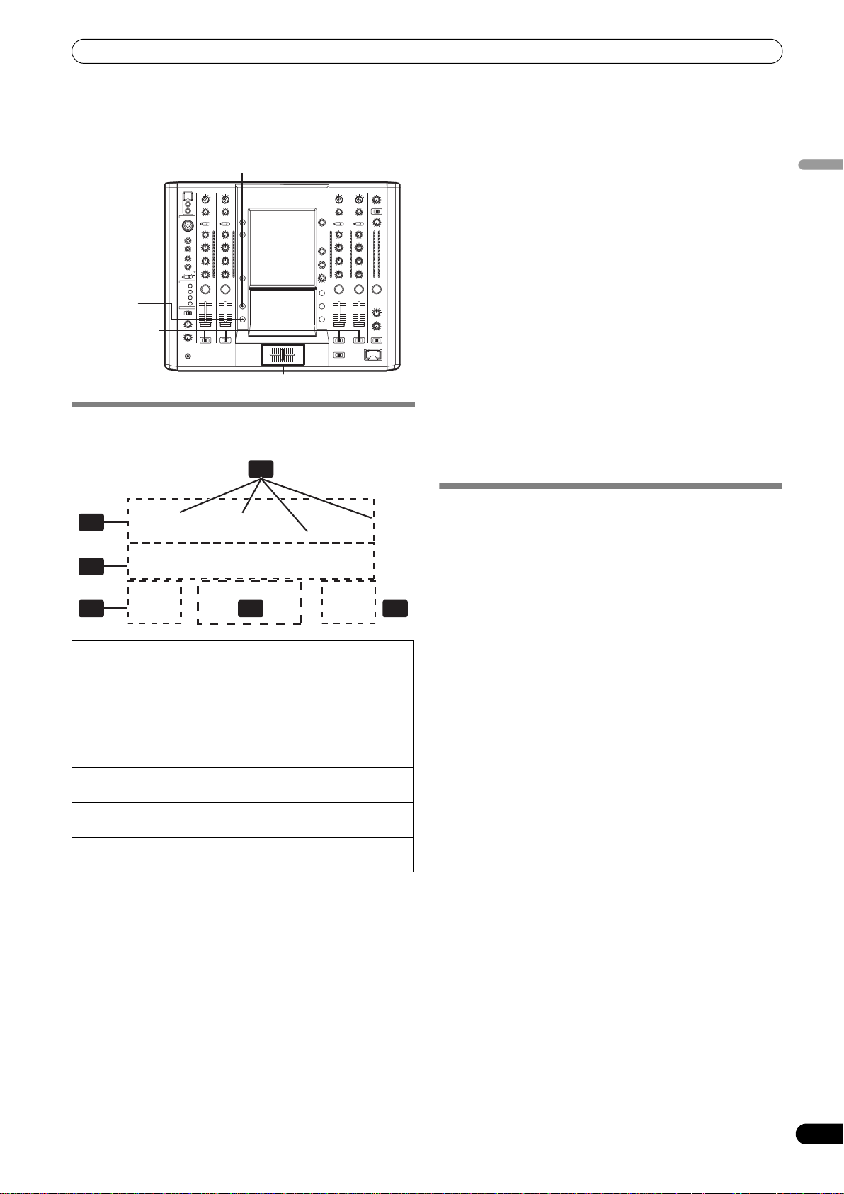
38 Channel fader curve switch (CH FADER CURVE)
This switch allows the user to select from three types of channel
fader curve response.
The sound volume and video level changes as follows:
This setting is applied equally to channels 1 to 4.
• At the left setting, the curve operates to produce a rapid rise as
the channel fader approaches its distant position.
• At the right setting, the curve operates to produce an even,
neutral rise throughout the channel fader’s movement.
• At the middle setting, an intermediate curve is produced,
midway between the two curves noted above.
39 SD CARD slot
Insert an SD card.
40 UTILITY button (MASTER MONITOR, SET UP)
Switches between display / no display of the master monitor on the
LCD. When the master monitor is set to display, the indicator
lights. When the button is held depressed, the indicator changes
to flashing, and the LCD screen changes to show the utility setup
menu.
41 VIDEO EQ button (ON/OFF, SET UP)
Switches the video equalizer ON/OFF. The indicator lights when
the video equalizer is ON. When the button is held depressed, the
indicator flashes, and the LCD display changes to show the
equalizer setup menu.
42 JPEG VIEWER button
Use to set the JPEG viewer mode. The indicator lights when in the
JPEG viewer mode.
43 VIDEO SOLO MODE button
Use to switch the video solo mode ON/OFF. When the video solo
mode is ON, the indicator will flash.
44 Fader AV synchro button (FADER AV SYNC)
This button determines whether sound and video are controlled
together, or independently. When set to ON, the indicator lights,
and the channel fader and cross fader operations change both
sound and video simultaneously. When set to OFF, the channel
fader and cross fader levers control sound only, while video is
controlled by the touch panel.
45 Effect channel selector dial (CH SELECT)
Use to select the channel to which effects are applied. When [MIC]
is selected, effects are applied to both microphone 1 and
microphone 2.
46 VIDEO FX PATTERN/TEXT BANK dial
Use to select video effects, video effect patterns and text banks.
47 Effect parameter 1 dial (TIME/PARAMETER)
Adjusts parameter for selected effect.
• If this dial is rotated while depressing the TAP button, direct
BPM can be set manually.
48 Effect parameter 2 dial (LEVEL/DEPTH)
Adjusts quantitative parameters for selected effect.
49
TAP
button
The BPM is calculated from the intervals at which the TAP button
is struck.
50 Effect button/indicator (EFFECT ON/OFF)
Turns selected effect ON/OFF.
When power is turned ON, the button lights (defaults to effect
OFF). When effects are enabled (ON), the button flashes.
51 Cross fader lever (A/B)
This adjusts sound and video levels assigned to sides [A] and [B]
in accordance with the CROSS FADER ASSIGN switches. When
FADER AV SYNC is OFF, the control adjusts the sound only.
English
En
9
Page 10
CONNECTIONS
POWER
AC IN
ON
OFF
DVD
VIDEO
S-VIDEO
MASTER OUT 1
1 GND 2 HOT
MASTER
ATT.
MASTER
COMPONENT COMPOSITE
YC
B CR
-3 dB
-6 dB 0 dB
3 COLD
DIGITAL OUT
DVD
VIDEO
S-VIDEO
S-VIDEO S-VIDEO
MONITOR
L
MASTER
OUT 2
BOOTH
MONITOR
(TRS)
L
R
LR
REC
OUT
R
DVD
VIDEO
S-VIDEO
DVD
USB
OUT
VIDEO
S-VIDEO
AUDIO OUT
VIDEO OUT
L
fs (Hz)
48 k 96 k
MIC2
MIDI
PHONO
SIGNAL GND
L
R
DVD/LINE
4 3
CONTROL
SYNC
OUT
LINE
DIGITAL
IN
CONTROL
SYNC
OUT
R
DVD LINE
SIGNAL GND
CONTROL
SYNC
OUT
L
R
DVD PHONO
DIGITAL
IN
CONTROL
SYNC
OUT
L
R
DVD/LINE
21
L R L R L RL R L R LR
Analog turntable Analog turntableDJ/VJ DVD player or
DJ CD player
DJ/VJ DVD player or
DJ CD player
Cassette deck, etc.
CD player, etc.
CONNECTIONS
Always turn off the power switch and disconnect the power plug from its outlet when making or changing connections.
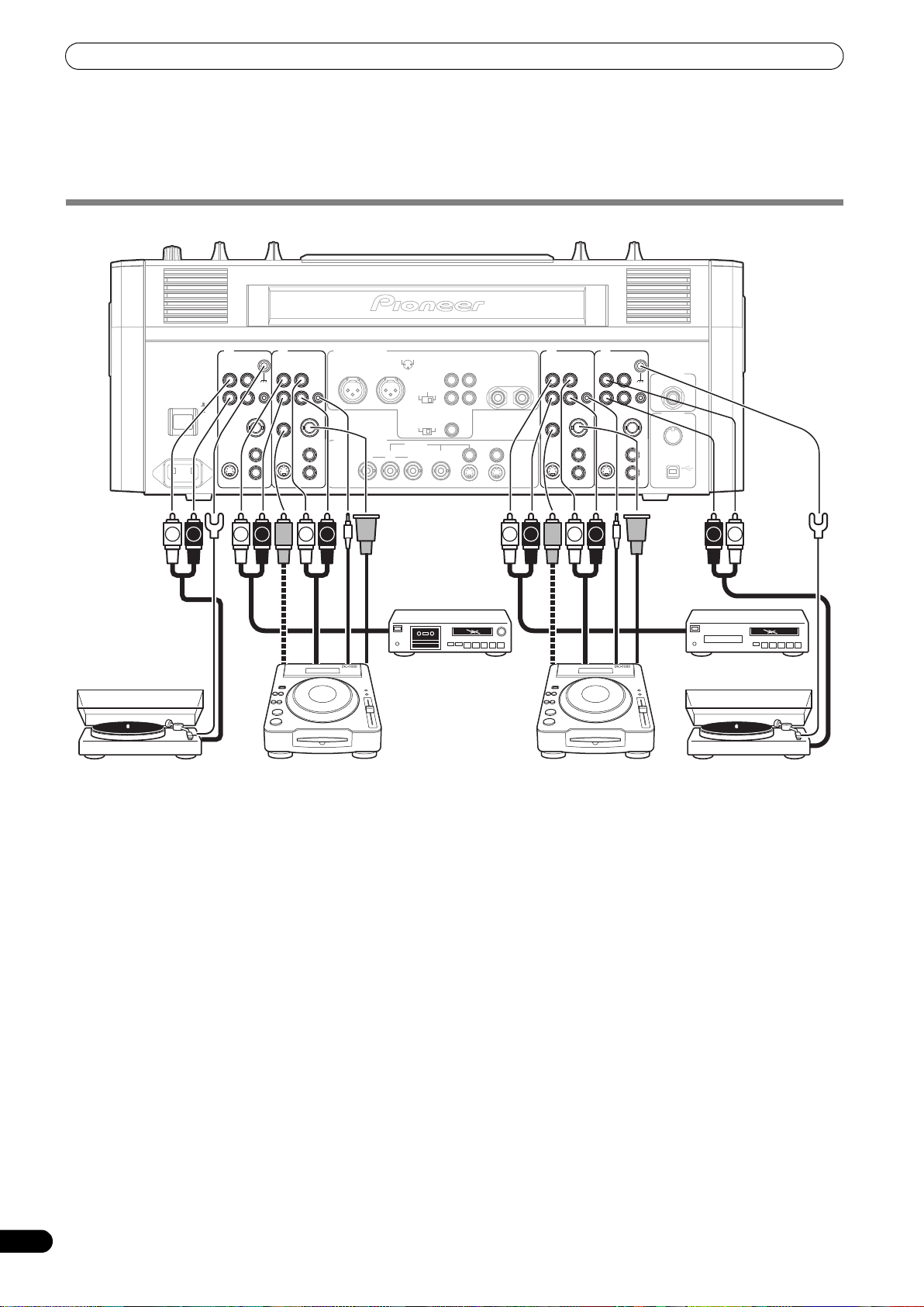
CONNECTING INPUTS
Pioneer DJ/VJ DVD players or DJ CD players
Audio cable connection
A DJ/VJ DVD or DJ CD player’s audio output connectors can be
connected to this unit’s DVD, DVD/LINE or LINE connectors.
When using the player’s digital output, connect to this unit’s
channel 2 or channel 3 DIGITAL IN connector. Use the AUDIO
INPUT selector switch (on top panel of this unit) to select the
proper connector.
Likewise, the control cord should be connected to the CONTROL
connector of the selected channel.
Video cable connection
A DJ/VJ DVD player’s video output connectors can be connected
to this unit’s DVD, VIDEO, or S-VIDEO connectors. When this is
done, use the VIDEO INPUT selector switch (on top panel of this
unit) to select the proper connector.
Likewise, connect a commercially available sync signal cable to
the SYNC OUT connector of the selected channel.
10
En
Connecting an analog turntable
Connect the audio output cables from an analog turntable to this
unit’s Channel 1 or 4 PHONO input connectors, then set the
connected channel’s AUDIO INPUT switch (on the upper panel of
this unit) to [PHONO]. This unit’s PHONO input supports MM
cartridges.
Connect the ground wire from an analog turntable to the SIGNAL
GND terminal of the SVM-1000.
•Note that no PHONO input connector is provided for channel 2
and 3.
Connecting other line level output devices
To use a cassette deck or ordinary CD player, connect its audio
output connectors to one of the SVM-1000's LINE input connectors
(channel 1 to 4).
Page 11
CONNECTIONS
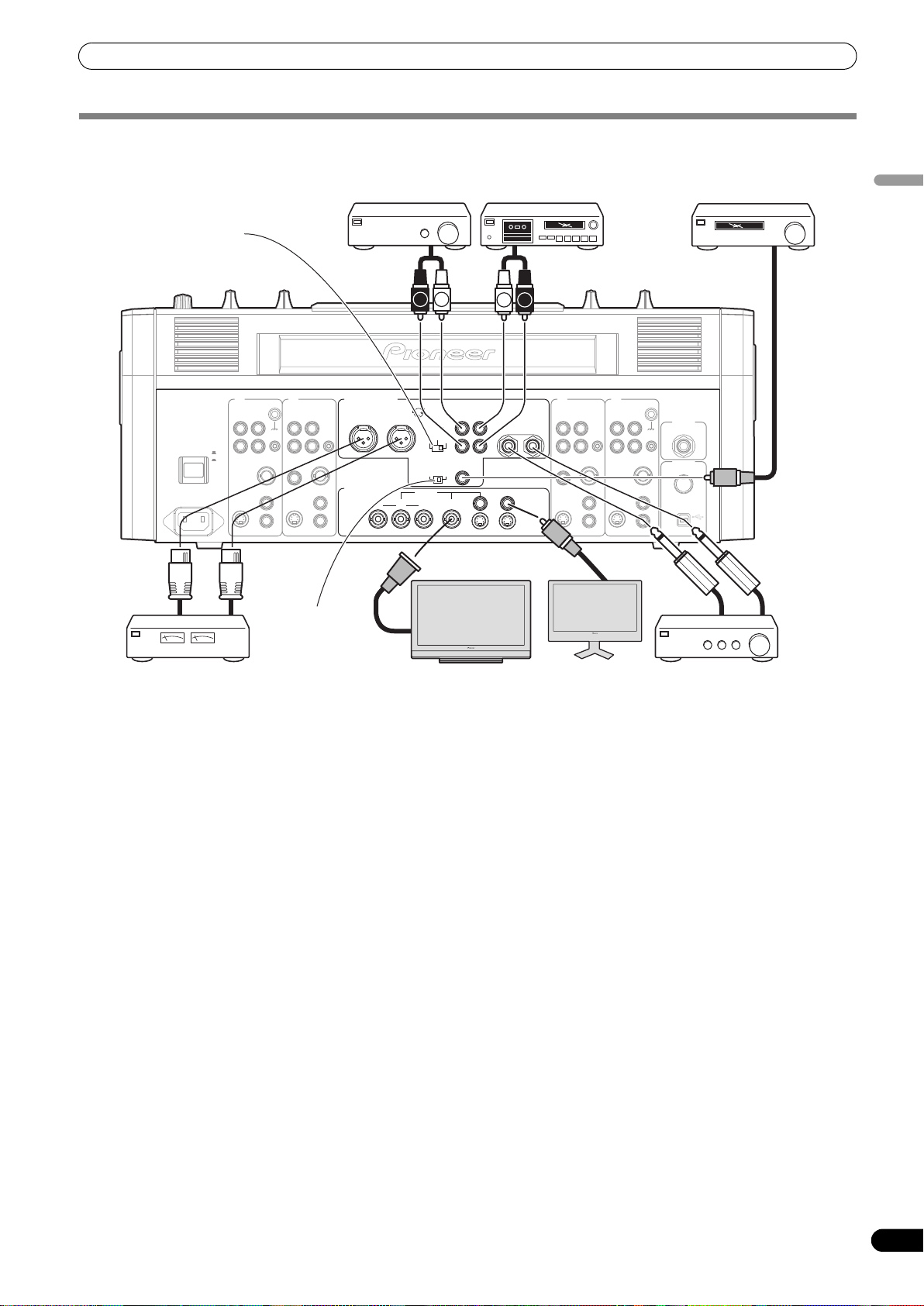
CONNECTING OUTPUTS
MASTER ATT. switch
OFF
POWER
ON
AC IN
4 3
SIGNAL GND
PHONO
DVD/LINE LINE
L
CONTROL
R
SYNC
OUT
DVD
S-VIDEO
VIDEO
L
R
DIGITAL
IN
S-VIDEO
DVD
CONTROL
SYNC
OUT
DVD
VIDEO
Power amplifier
(RCA plug input
connectors)
AUDIO OUT
VIDEO OUT
MASTER OUT 1
L
R
COMPONENT COMPOSITE
B CR
YC
1 GND 2 HOT
3 COLD
-6 dB 0 dB
MASTER
MASTER
ATT.
-3 dB
DIGITAL OUT
fs (Hz)
48 k 96 k
Cassette deck
(analog input
recording device)
LR
MASTER
L
R
OUT 2
S-VIDEO S-VIDEO
L R
REC
OUT
MONITOR
21
LINE
BOOTH
MONITOR
(TRS)
L
LR
R
DIGITAL
IN
S-VIDEO
DVD PHONO
L
CONTROL
R
SYNC
OUT
DVD
S-VIDEO
VIDEO
DVD/LINE
Digital input AV amplifier
(digital input
recording device)
SIGNAL GND
MIC2
CONTROL
SYNC
OUT
MIDI
OUT
DVD
USB
VIDEO
English
Sampling
frequency
selector switch
Power amplifier
(XLR plug input connectors)
Plasma display Display
Audio master output
This unit is furnished with balanced output MASTER OUT 1
(supporting XLR plugs), and unbalanced output MASTER OUT 2
(supporting RCA plugs).
Using the MASTER ATT. switch, adjust the output level to match
the input sensitivity of the power amplifier used.
If the operating panel’s MONO/STEREO switch is set to [MONO],
the master output will be a monaural combination of L+R
channels.
Booth monitor output
TRS output for ø 6.3 mm phone plug. The sound volume for this
output is controlled by the BOOTH MONITOR level dial,
independently of the master output level setting.
Power amplifier
(for monitor)
(for booth monitor)
Recording output
These are output connectors for recording, supporting RCA plugs.
Digital output
This is a coaxial digital output connector, supporting RCA plugs.
The sampling frequency can be set to 96 kHz/24-bit format or
48 kHz/24-bit format to match the connected device.
Turn power off before changing this switch position.
Video master output
Supports component, composite (RCA, BNC connector) and SVIDEO outputs.
Monitor output
Supports composite and S-VIDEO outputs.
11
En
Page 12
CONNECTIONS
O
-
9
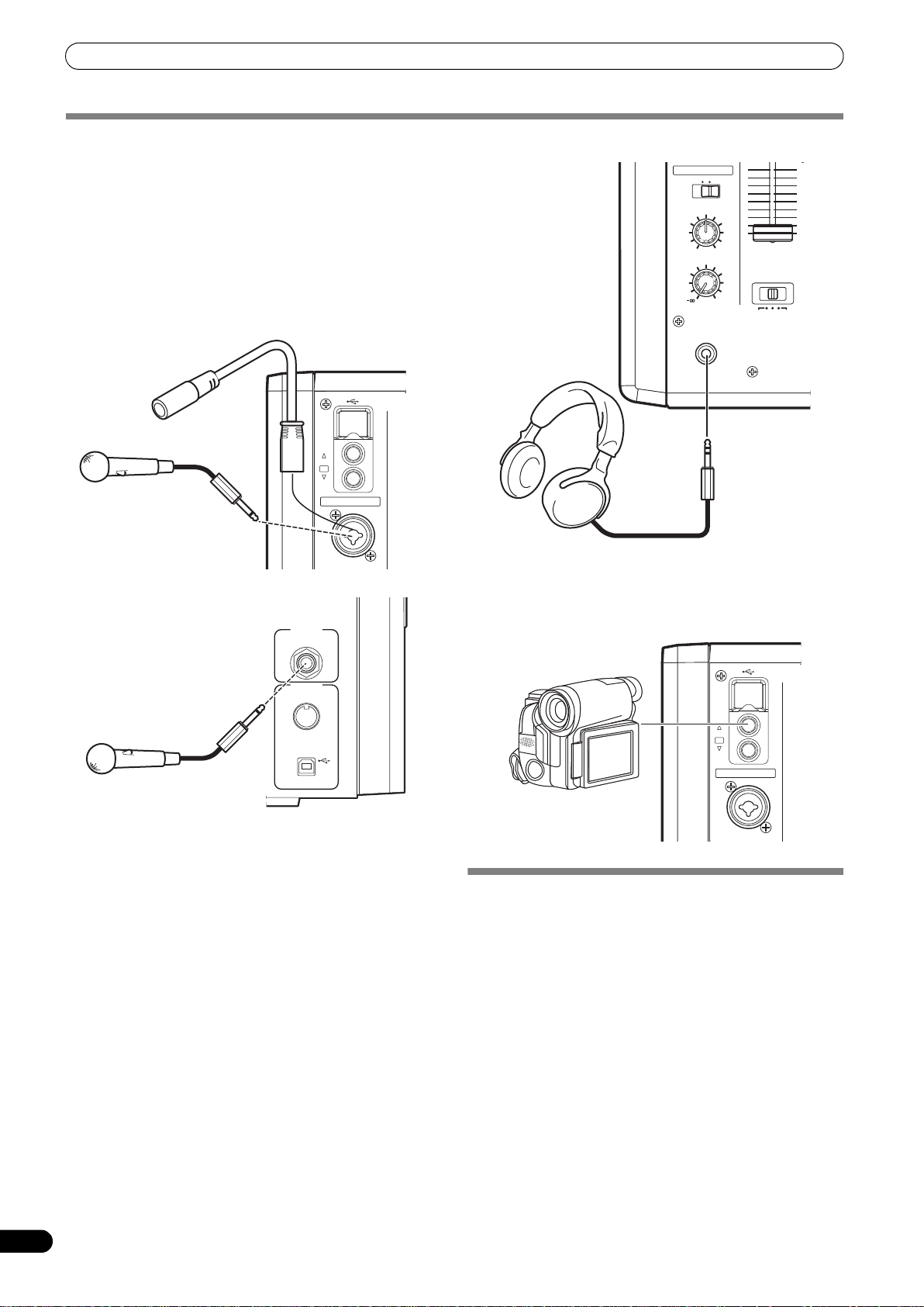
CONNECTING MICROPHONE AND HEADPHONES
Microphone
A microphone with XLR-type or Ø 6.3 mm phone-type plug can be
connected to the MIC 1 connector on the operation panel (upper) .
The MIC 2 jack on the connection panel (rear) can be used to
connect a microphone with Ø 6.3 mm phone-type plug.
• When using a microphone, set the operating panel’s MIC switch
to [ON] or [TALK OVER], and adjust the LEVEL dial as
necessary.
When not using a microphone, it is recommended to set the
MIC switch to [OFF] and rotate the LEVEL dial fully
counterclockwise to the [–∞] side.
MIC2
USB
CH 1
VIDEO
CH 4
EX
MIC
MIC 1
Microphone 1
HEAD PHONES
MONO SPLIT STEREO
MIXING
MASTER
CUE
LEVEL
PHONES
Headphones
0
CROSS FADER
ASSIGN
A THRU B
PROFESSIONAL S
SVM
External video connector
A camera, DVD player or other video output device can be
connected to the CH 1/CH 4 video input connectors on the
operating panel (top).
8
7
6
5
4
3
2
1
0
MIDI
OUT
Microphone 2
USB
Headphones
The PHONES jack on the operating panel (upper) can be used to
connect headphones with a Ø 6.3 mm stereo phone plug.
USB
CH 1
VIDEO
EX
CH 4
MIC
Video cameras and
devices
MIC 1
CONNECTING THE POWER CORD
Connect the power cord last.
When all connections are completed, connect one end of the
furnished power cord to the AC inlet on the rear panel, and the
plug on the other end to a household AC outlet, or the auxiliary
power outlet on an amplifier. Use only the furnished power cord for
this connection.
12
En
Page 13
BASIC OPERATIONS
BASIC OPERATIONS
VIDEO
INPUT
AUDIO
INPUT
HI, MID,
LOW
Channel fader
CROSS FADER
lever
ASSIGN
1 Set rear panel POWER switch to [ON].
2 Set the AUDIO INPUT switch for the desired channel to match
the type of connected component.
• When using the DVD input, set to [DVD].
• When using LINE input, set to [LINE].
• When using DVD/LINE input, set to [DVD/LINE].
• When using DIGITAL input, set to [DIGITAL].
• When using PHONO input, set to [PHONO].
3 Use the VIDEO INPUT switch for the selected channel to
choose the video input.
4 Use the AUDIO TRIM dial to adjust the input level for each
channel.
5 Use the VIDEO TRIM dial to adjust the input level for each
channel.
HI
POWER
VIDEO MASTER LEVEL
VIDEO TRIM
AUDIO MASTER LEVEL
AUDIO TRIM
HI, MID,
LOW
10
10
9
9
8
8
7
7
6
6
5
5
4
4
3
3
2
2
1
1
0
0
BALANCE
Cross fader lever
(A/B)
6 Use the channel equalizer dials (HI, MID, LOW) to adjust the
tone.
7 Use the channel fader lever to adjust the sound volume of
the selected channel.
8 To use the cross fader on the selected channel, set the CROSS
FADER ASSIGN switch to either cross fader channel A or
channel B, and operate the cross fader lever (A/B).
• When not using the cross fader, set the
ASSIGN
switch to [THRU].
CROSS FADER
9 Use the AUDIO MASTER LEVEL dial to adjust the overall
sound volume.
10 Use the VIDEO MASTER LEVEL dial to adjust the overall
luminance level.
11 Use the BALANCE dial to adjust the sound balance between
right and left.
English
13
En
Page 14
BASIC OPERATIONS
MONO/STEREO
MIC1 LEVEL
MIC2 LEVEL
HI, LOW
MIC
CUE
MONO SPLIT/STEREO
MIXING
LEVEL
HI
Selecting Stereo or Monaural
When the MONO/STEREO switch is set to [MONO], the audio
master output becomes a monaural combination of L+R
channels.
Microphone Input
1 To use a microphone, set the MIC switch to [ON] or [TALK
OVER].
When set to [
TALK OVER
], any time a sound of –15 dB (default
setting) or more is input, all sound sources other than the
microphone are attenuated by 20 dB (default setting). These
default values can be changed in the hardware setup (P. 42).
2 Use the MIC 1 LEVEL dial to adjust the sound volume of
MIC 1, and use the MIC 2 LEVEL dial to adjust the sound
volume of MIC 2.
3 Use the microphone equalizer dials (HI, LOW) to adjust the
tone of the microphone sound.
• The microphone equalizer function operates simultaneously
on microphone 1 and 2.
Booth Monitor Output
1 Use the BOOTH MONITOR level dial to adjust the sound
volume.
•The
BOOTH MONITOR
level dial can be used to adjust the
sound volume independently of the AUDIO MASTER LEVEL
dial.
• Use the hardware setup (P. 42) to set whether or not the
microphone sound is to be output to the booth monitor.
Headphones Output
1 Use the headphone CUE buttons (channels 1 to 4, MASTER,
EFFECT CUE) to select the source.
•The selected
2 Set the HEADPHONES (MONO SPLIT/STEREO) switch.
• When set to the [MONO SPLIT] position, the sound selected
with the headphone
and the master sound is output to the right channel (only
when MASTER CUE button is set to ON).
• When set to the [STEREO] position, the sound selected with
the headphone
3 When [MONO SPLIT] is selected, use the HEADPHONES
MIXING dial to adjust the balance of sound between the left
channel (sound selected with the headphone CUE button),
and the right channel (master sound).
• When the
(toward [MASTER]), the master output (only when the
MASTER CUE button is ON) increases; when rotated
counterclockwise (toward [
the headphone
CUE
button lights brightly.
CUE
button is output to the left channel,
CUE
button is output in stereo.
HEADPHONES MIXING
CUE
CUE
button increases.
]), the sound selected with
dial is rotated clockwise
10
10
9
9
8
8
7
7
6
6
5
5
4
4
3
3
2
2
1
1
0
0
CROSS FADER CURVE
BOOTH MONITOR
CH FADER CURVE
4 Use the HEADPHONES LEVEL dial to adjust the headphones’
sound volume.
• Rotate the HEADPHONES LEVEL dial to adjust the sound
level.
• When the Effect mode select button (P. 17) is set to [V]
mode, effect sounds will not be output even if the
EFFECT CUE button is pressed.
FADER CURVE SELECTION
The response of sound volume change to the fader control can be
set in three types.
Use the CH FADER CURVE switch to select the desired channel
fader response curve.
The sound volume and video level changes as follows:
• At the left setting, the curve operates to produce a rapid rise as
the channel fader approaches its distant position.
• At the right setting, the curve operates to produce an even,
neutral rise throughout the channel fader’s movement.
• At the middle setting, an intermediate curve is produced,
midway between the two curves noted above.
• This setting applies equally to channels 1 to 4.
Use the CROSS FADER CURVE switch to select the cross fader
curve response.
Sound volume changes as follows:
• At the left setting, the curve produces a rapid signal rise. (As
soon as the cross fader lever leaves the [A] side, the [B] channel
sound is produced.)
• At the right setting, the curve operates to produce an even,
neutral rise throughout the cross fader’s movement.
• At the middle setting, an intermediate curve is produced,
midway between the two curves noted above.
• This setting produces equal curve effects for both sides A and B.
The video level is as noted above only when the video cross fader’s
video mix effect is set to [FADE].
14
En
Page 15
USING THE VIDEO CONTROL FUNCTIONS
3
5 54
1
2
USING THE VIDEO CONTROL FUNCTIONS
Touch the LCD screen to control video functions. Supports video cross fader functions and video channel switch functions.
VIDEO SOLO MODE
HI
10
10
9
FADER A V
SYNC
CROSS FADER
ASSIGN
Cross fader lever (A/B)
9
8
8
7
7
6
6
5
5
4
4
3
3
2
2
1
1
0
0
OPERATING THE VIDEO CROSS FADER
The video cross fader is used to manipulate video images.
2 Touch a video mix effect button to choose a video mix effect.
• The selected button will appear white, and the icon will move
as an animation.
• For each effect refer to P. 16.
3 Operate the video cross fader.
• The video will change as video mix effects are being applied.
• When FADER AV SYNC is set to ON, the video cross fader
section’s [AV SYNC] indicator will appear, and the video
cross fader will operate in synchronization with the cross
fader. Touching the video cross fader allows you to
manipulate the video while you are touching it. Release to
return to the same position as the cross fader.
• When FADER AV SYNC is set to OFF, the video cross fader
section’s [AV SYNC] indicator goes out, and the sound and
video are controlled independently. The sound is controlled
by the cross fader, and the video by the video cross fader.
•When the [TRANS] button is touched, the video
corresponding to the touched side will be output regardless
of the position of the video cross fader.
• When all cross fader assigns are set to [THRU], the video
cross fader and [TRANS] button will appear gray, and if
assigned, the buttons will function as video cross fader,
[TRANS] buttons, with [A] side appearing blue and [B] side
appearing red.
English
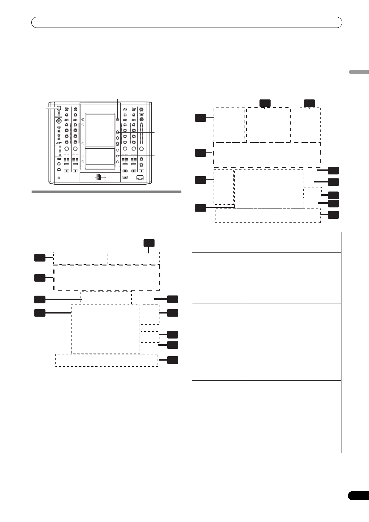
1 Channel
monitor
Monitors videos from each input channel
(1 through 4).
Touch the channel monitor to output the
video of each channel.
2 Video level
Indicates video output level.
Appears red when FADER AV SYNC is
ON, and appears green when FADER AV
SYNC is OFF.
3 Video mix effect
button
4 Video cross
Use to select type of video change when
video cross fader is operated.
Video cross fader.
fader
5 Transfomer
button [TRANS]
Outputs video of touched side, regardless
of position of video cross fader.
1 Using the CROSS FADER ASSIGN switch, choose either
Channel A or Channel B of the cross fader
• When assigned to Channel [A], the border of the channel
preview monitor appears blue; when assigned to Channel
[B], the border of the channel preview monitor appears red.
When assigned to [THRU], the border appears gray.
• When JPEG is assigned, the [JPEG] indicator will appear at
the upper left of the channel monitor.
OPERATING THE VIDEO CHANNEL SWITCH
The channel monitor functions as a switch to turn that channel’s
video ON/OFF.
1 Touch the channel monitor.
• The touched video output will alternate ON/OFF.
• When FADER AV SYNC is set to ON, the video level will be
displayed in red. If the video level is not dispayed (channel
fader is [0]), touch the channel to output that channel’s
video. Or alternately, when the video level is displayed,
touching the channel monitor will cause that channel’s
video to turn off during the duration the screen is touched.
• When FADER AV SYNC is set to OFF, the video level is
displayed in green. The channel monitor can be touched to
alternate that video output ON/OFF.
15
En
Page 16
USING THE VIDEO CONTROL FUNCTIONS
OPERATING IN THE VIDEO SOLO MODE
Setting video solo mode to ON allows instantaneous switching to
the desired channel’s video.
By combining with the FADER AV SYNC button ON/OFF, a variety
of operations is possible.
Whenever the power is first turned ON, the video solo mode is set
to OFF by default.
When the video solo mode is ON, the VIDEO SOLO MODE button
will flash.
• When the channel monitor is touched, output instantaneously
switches to the video of the touched channel.
• When the channel fader begins rising from the [0] position,
output instantaneously switches to that channel’s video.
When
FADER
AV SYNC is OFF
• When the channel monitor is touched, output instantaneously
switches to the video of the touched channel.
Upon changing the FADER AV SYNC from ON to OFF, the original
channel fader position will be maintained until the channel
monitor is touched again.
Operation of the video cross fader and [TRANS] button are not
supported in the video solo mode.
VIDEO MIX EFFECTS CHART
Video mix effects
Video cross fader
No Name Description of the effect
1 FADE Switches video while mixing.
2 WIPE Switches video while wiping away.
3 SWITCH Switches instantaneously (without mixing).
When FADER AV SYNC is ON
4 CHROMA-B Switches from the blue component of video on cross fader side [A] to the
5 CHROMA-G Switches from the green component of video on cross fader side [A] to the
6 LUMINANCE Switches from the dark portion of video on cross fader side [A] to the video
video on side [B].
video on side [B].
on side [B].
16
En
Page 17
USING THE EFFECT FUNCTION
1
5
6 7
11
8
10
9
4
2
USING THE EFFECT FUNCTION
This function applies effects to the selected channel’s sound and video. Effects include BEAT effects, which are applied in linkage to the
track’s BPM; TOUCH effects, which control effects by directly touching the screen; and TEXT effects, which display onscreen characters
with effects added in rhythm to the track. The UTILITY (MASTER MONITOR) button can be pressed to display the master monitor’s image
on the LCD screen.
When master monitor is on
1
2
5
3
4
7
11
USB
UTILITY
(MASTER MONITOR) CH SELECT
HI
10
9
8
7
6
5
4
3
2
1
0
VIDEO FX
PATTERN
10
9
8
7
6
5
4
3
2
1
0
TAP
EFFECT
ON/OFF
English
USING BEAT EFFECTS
BEAT effects can be instantaneously set in-sync with the BPM
(Beat Per Minute) of the track, enabling you to apply various effects
to the rhythm even during live performances.
6
8
9
10
When master monitor is off
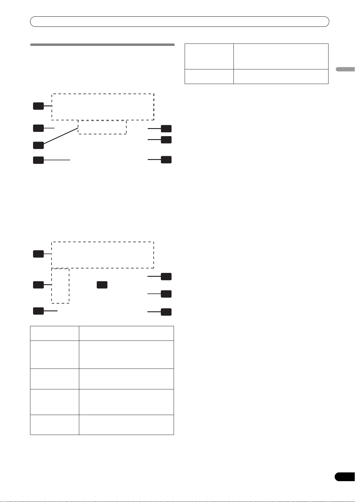
1 Effect category
buttons
Selects the category of effects you wish to
apply. Select from [BEAT] (red), [TOUCH]
(blue), and [TEXT] (green).
2 Effect select
buttons
3 MASTER
monitor
4 Channel select
display
Select and touch the desired effect button
from the 12 BEAT effects.
When master monitor is on, displays
master output.
Rotate the CH SELECT dial to select the
channel to which you wish to apply the
effect.
5 Effect mode
select buttons
A: Touch to apply the effect to audio only.
AV: Touch to apply the effect to both
audio and video.
V: Touch to apply the effect to video only.
6 Video EFFECT
Monitors effect results.
monitor
7 Video effect
pattern display
Rotate the VIDEO FX PATTERN/TEXT
BANK dial to select the video effect
pattern. When BEAT effect is enabled, you
can choose from
[ORIGINAL]/[INVERSE]/[EDGE]/[HUE].
8[BPM
AUTO/TAP]
button
9 BPM/parameter
display
10 Beat button
Touch to switch the measurement
method of the BPM between AUTO and
TAP.
Displays the measured BPM and effect
parameters.
Touch to select the multiplication factor
of the beat calculated from the BPM for
11 [VISUALIZER]
button
synchronization of effects.
Allows use of images produced internally
by the unit.
17
En
Page 18

USING THE EFFECT FUNCTION
1 Touch the [BPM AUTO/TAP] button to select the BPM (=Beat
Per Minute) measurement mode.
AUTO: The BPM is automatically measured from the input
music signal.
TAP: Tap the TAP button with your finger to manually input the
BPM.
• Whenever power is first turned ON, [AUTO] is selected by
default.
•The selected mode ([AUTO]/[TAP]) will appear in the
display.
• When a BPM cannot be measured automatically, the BPM
display in the display will flash.
• The measurement range of AUTO mode is BPM=70 to 180.
Depending on the track, the BPM may not be accurately
measured. In these cases, use TAP mode to manually enter
the BPM.
[Manually entering the BPM using the TAP button]
When the TAP button is tapped to the beat (a quarter note) more
than twice, the average length will be set as the BPM.
•Pressing the TAP button during [AUTO] mode will switch the
BPM measurement mode to [TAP], and the length between the
taps will be measured.
• When a BPM is set using the TAP button, the multiplication
factor will become [1/1] or [4/1] (depending on the effect), and
the effect time will be set to either the length of 1 beat (a quarter
note) or 4 beats.
• Rotate the TIME/PARAMETER dial while pressing the TAP
button to set the BPM directly.
•Touch the [BPM AUTO/TAP] button to return to [AUTO] mode.
2 Touch the effect category button [BEAT].
•The [BEAT] button will light brightly, and the icon will move
as an animation.
• The BEAT effect screen will be displayed.
• Whenever power is first turned ON, the [BEAT] effect is
selected by default.
3 Use the effect select buttons to select an effect type.
• The selected button will appear white, and the icon will move
as an animation.
• For a description of each effect, refer to P. 23.
4 Use the CH SELECT dial to select the channel to which you
wish to apply the effect.
• The selected effect channel display will appear white.
•If [MIC] is selected, the audio effect will be applied to both
MIC 1 and MIC 2. There will be no effect on the video.
• When turning the power ON, [MASTER] will be selected.
5 Touch the effect mode select button to select the effect
mode.
• The selected button will appear white, and the icon will move
as an animation.
A: The effect will be applied to the audio only.
AV: The effect will be applied to both the audio and video.
V: The effect will be applied to the video only.
• When turning the power ON, [AV] will be selected.
6 Touch the beat button to choose the multiplication factor of
the beat for synchronization of the effect.
• Select the beat number calculated from the BPM.
• The selected beat button will be highlighted.
• An effect time that corresponds to the multiplication factor
of the beat will be automatically set.
[Example] When BPM=120
1/1 = 500 ms
1/2 = 250 ms
2/1 = 1000 ms
7 Set the EFFECT ON/OFF button to ON to apply the effect.
• Each time the button is pressed it will switch between ON
and OFF (whenever power is first turned ON, the setting
defaults to OFF).
• When effect is ON, the button flashes.
Video effect pattern
Rotate the VIDEO FX PATTERN/TEXT BANK dial to select a video
effect pattern for the selected video effect.
For descriptions on the video effect pattern change caused by
rotating the VIDEO FX PATTERN/TEXT BANK dial, refer to P. 24.
Parameter 1
Rotate the TIME/PARAMETER dial to adjust temporal parameters
of the selected effect.
For descriptions on the changes in parameter 1 caused by turning
the TIME/PARAMETER dial, refer to P. 23.
Parameter 2
Rotate the LEVEL/DEPTH dial to adjust quantitative parameters of
the selected effect.
For descriptions on the changes in parameter 2 caused by rotating
the LEVEL/DEPTH dial, refer to P. 23.
Using the visualizer
This function allows the use of images produced internally by the
unit.
1 Set [VISUALIZER] button to [ON].
The video effect monitor displays the image.
2 Use the effect select buttons to choose a desired image.
3 Use the CH SELECT dial to select the desired channel.
• The image will move automatically in rhythm to the music’s
beat.
• In the event no input image is present, the visualizer’s image
can be used.
18
En
Page 19
USING THE EFFECT FUNCTION
2
7
4
5
6
3
1
4
5
7
1
6
2 23
USING TOUCH EFFECTS
With TOUCH effects, many effects can be created by touching the
video EFFECT performance monitor.
When master monitor is off
When master monitor is on
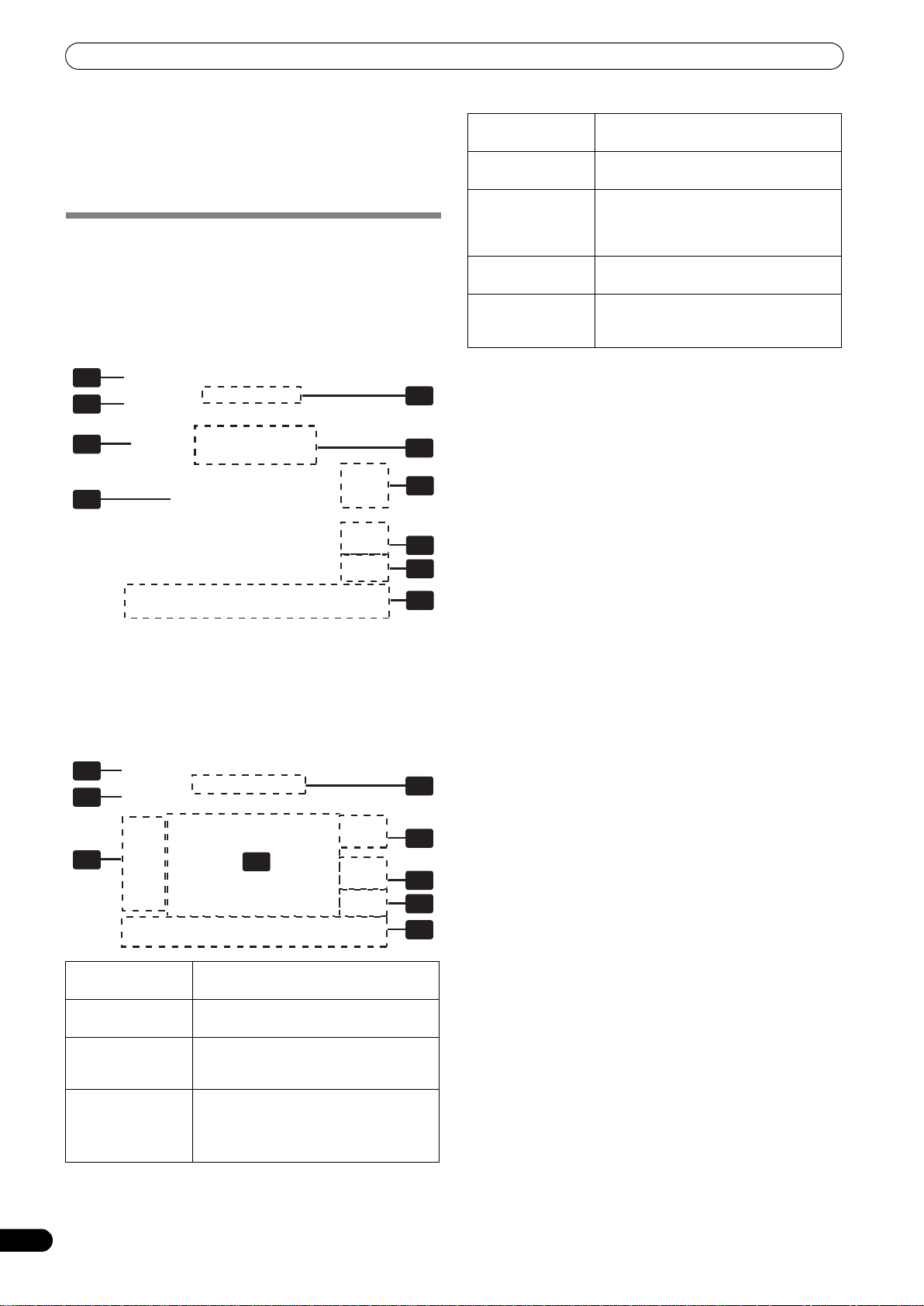
1 Effect select
buttons
2 Effect mode
select buttons
3 Video EFFECT
performance
monitor
4 Video effect
pattern display
5 Parameter
display
Select and touch the desired effect button
from the 12 TOUCH effects.
A: Touch to apply the effect to audio only.
AV: Touch to apply the effect to both
audio and video.
V: Touch to apply the effect to video only.
Touch here to apply effects to the video
image.
Rotate the VIDEO FX PATTERN/TEXT
BANK dial to select the video effect
pattern. The pattern will differ depending
on the effect type.
Displays the TOUCH effect parameter.
The parameter will differ depending on
the effect type
6 [HOLD] button
7 [VISUALIZER]
button
1 Touch the effect category button [TOUCH].
•The [TOUCH] button will light brightly, and the icon will
move as an animation.
• The TOUCH effect screen will be displayed.
2 Select an effect from the effect select buttons.
• The selected button will appear white, and the icon will move
as an animation.
• For a description of each effect, refer to P. 25.
3 Use the CH SELECT dial to select the channel to which you
wish to apply the effect.
• The selected effect channel display will appear white.
•If [MIC] is selected, the audio effect will be applied to both
MIC 1 and MIC 2. There will be no effect on the video.
4 Touch the effect mode select button to select the effect
mode.
• The selected button will appear white, and the icon will move
as an animation.
A: The effect will be applied to the audio only.
AV: The effect will be applied to both the audio and video.
V: The effect will be applied to the video only.
• When turning the power ON, [AV] will be selected.
5 Set the EFFECT ON/OFF button to ON to apply the effect.
• Each time the button is pressed it will switch between ON
and OFF (whenever power is first turned ON, the setting
defaults to OFF).
• When effect is ON, the button flashes.
6 Touch the video effect performance monitor to change the
effects.
•When [HOLD] button is set to [ON], effects are recorded
from the time the screen is touched until the finger is
removed (max. 8 sec.), then output repeatedly.
•Each time the [HOLD] button is touched it will switch
between [ON] and [OFF].
• Whenever power is first turned ON, the setting defaults to
[OFF].
Pattern
Rotate the VIDEO FX PATTERN/TEXT BANK dial to select a video
effect pattern of the selected video effect.
For descriptions of the video pattern changes caused by rotating
the VIDEO FX PATTERN/TEXT BANK dial, refer to P. 25.
Parameter 1
Rotate the TIME/PARAMETER dial to adjust the parameters for
the selected effect.
For descriptions on the changes in parameter 1 caused by rotating
the TIME/PARAMETER dial, refer to P. 25.
Parameter 2
Rotate the LEVEL/DEPTH dial to adjust the quantitative
parameters for the selected effect.
For descriptions on the changes in parameter 2 caused by rotating
the LEVEL/DEPTH dial, refer to P. 25.
Using the Visualizer
This function allows the use of images produced internally by the
unit.
1 Set [VISUALIZER] button to [ON].
The video effect performance monitor displays the image.
When [HOLD] button is set to [ON],
effects are recorded from the time the
screen is touched until the finger is
removed.
Internally creates a video image to which
TOUCH effects can be applied.
English
19
En
Page 20
USING THE EFFECT FUNCTION
1
2
5
6
3
7
8
9
4
3
2 Use the effect select buttons to choose a desired image.
3 Touch the image to apply changes.
4 Use the CH SELECT dial to select the desired channel.
• In the event no input image is present, the visualizer’s image
can be used.
USING TEXT EFFECTS
TEXT effects can be instantaneously set in-sync with the BPM
(Beat Per Minute) of the track, enabling you to apply various TEXT
effects to the rhythm.
When master monitor is off
When master monitor is on
1
2
3
6
4
5
7
8
9
1 Effect select
buttons
2 [TEXT BANK]
buttons
3 TEXT BANK
display
4 Effect mode
select button
Select and touch the desired effect button
from the 6 TEXT effects.
Touch the text button of your choice from
the 6 texts.
Rotate the VIDEO FX PATTERN/TEXT
BANK dial to select a TEXT BANK from
the 10 available.
A: Touch to apply the effect to audio only.
AV: Touch to apply the effect to both
audio and video.
V: Touch to apply the effect to video only.
5 Video EFFECT
monitor
6 [TEXT EDIT]
button
7[BPM
AUTO/TAP]
button
8 Parameter
display
9Beat
button/beat
display
1 Touch the [BPM AUTO/TAP] button to select the BPM (=Beat
Per Minute) measurement mode.
AUTO: The BPM is automatically measured from the input
music signal.
TAP: Tap the TAP butt on with your f inger to ma nually input the
BPM.
• Whenever power is first turned ON, [AUTO] is selected by
default.
•The selected mode ([AUTO]/[TAP]) will appear in the
display.
• When a BPM cannot be measured automatically, the BPM
display in the display will flash.
• The measurement range of AUTO mode is BPM=70 to 180.
Depending on the track, the BPM may not be accurately
measured. In these cases, use TAP mode to manually input
the BPM.
2 Touch the effect category button [TEXT].
•The [TEXT] button will light brightly, and the icon will move
as an animation.
• The TEXT effect screen will be displayed.
3 Select a text effect using the effect select buttons.
• The selected button will appear white, and the icon will move
as an animation.
• For a description of each effect, refer to P. 30.
4 Choose a text from TEXT BANK.
• Rotate the VIDEO FX PATTERN/TEXT BANK dial to select
TEXT BANK and touch the [TEXT BANK] button to select the
text.
• The selected button will appear white.
5 Use the CH SELECT dial to select the channel to which you
wish to apply the effect.
• The selected effect channel display will be highlighted.
• TEXT effects are not supported when [MIC] is selected.
Effects are applied to audio only.
6 Touch the effect mode select buttons to choose the effect
mode.
• The selected button will be highlighted and an animation
will appear.
A: An effect will be applied to the audio only.
AV: An effect will be applied to both the audio and video.
V: An effect will be applied to the video only.
• When turning the power ON, [AV] will be selected.
Monitors the TEXT effects.
Touch to edit the text of the selected
[TEXT BANK] button.
Touch to switch the measurement
method of the BPM between AUTO and
TAP. Pressing the TAP button will also
switch this to TAP.
Displays the measured BPM and effect
parameters.
Touch to select the multiplication factor
of the beat calculated from the BPM for
synchronization of effects.
20
En
Page 21

USING THE EFFECT FUNCTION
7 Touch the beat button to choose the multiplication factor of
the beat for synchronization of the effect.
• Select the beat number calculated from the BPM.
• The selected beat button will be highlighted.
• An effect time that corresponds to the multiplication factor
of the beat will be automatically set.
[Example] When BPM=120
1/1 = 500 ms
1/2 = 250 ms
2/1 = 1000 ms
8 Set the effect EFFECT ON/OFF button to ON to apply the
effect.
• Each time the button is pressed it will switch between ON
and OFF (whenever power is first turned ON, the setting
defaults to OFF).
• When effect is ON, the button is flashes.
Text bank
Rotate the VIDEO FX PATTERN/TEXT BANK dial to select a TEXT
BANK.
Parameter 1
Rotate the TIME/PARAMETER dial to adjust temporal parameters
of the selected effect.
For descriptions on the changes in parameter 1 caused by rotating
the TIME/PARAMETER dial, refer to P. 30.
Parameter 2
Rotate the LEVEL/DEPTH dial to adjust quantitative parameters of
the selected effect.
For descriptions on the changes in parameter 2 caused by rotating
the LEVEL/DEPTH dial, refer to P. 30.
English
21
En
Page 22
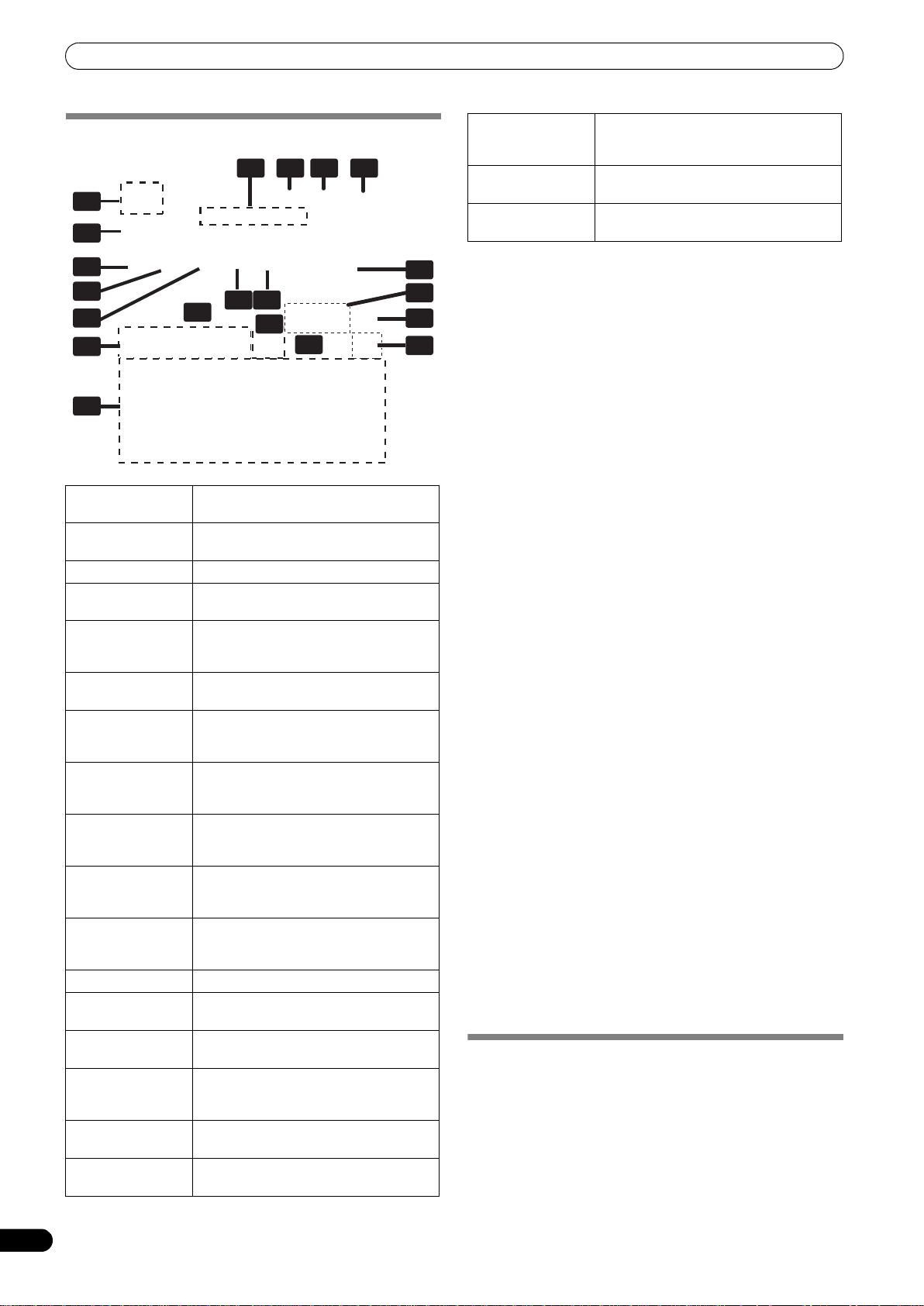
USING THE EFFECT FUNCTION
8
EDITING TEXT
1
6
7
8
9
121212
14
20
1 [EXIT] button
2[FACTORY TEXT]
button
3 [LOAD] button
4 [SAVE] button
5 TEXT BANK
display
6 [TEXT BANK]
buttons
7 [FONT] button
8 [COLOR] button
9[SIZE] button
10 Character
button
11 Justify button
12 TEXT BOX
13 TEXT effect
monitor
14 Text type select
buttons
15 [CAPS] / [PAGE]
button
16 Cursor move
button (<, >)
17 Line break
button (LF)
235 4
13
10 11
161615
161618
Touch to exit the TEXT EDIT screen and
return to the TEXT effect screen.
Touch to load factory text data.
Touch to load text data from an SD card.
Text entered into the TEXT BANK can be
saved to an SD card.
Rotate the VIDEO FX PATTERN/TEXT
BANK dial to select a TEXT BANK you
wish to edit from the 10 available.
Entered text can be stored.
Also touch to call up stored text.
Touch to change the font of the text. The
font alternates each time the button is
touched.
Touch to change the color of the entered
text. The color alternates each time the
button is touched.
Touch to change the size of the entered
text. The size alternates each time the
button is touched.
Touch to change the character of the
input text. The character alternates each
time the button is touched.
Touch to justify the text to the left, center,
or right. The justification alternates each
time the button is touched.
Displays the entered text.
The TEXT effect is monitored here.
Use to change the text type.
Touch to alternate between upper and
lower case, and between page display for
page 1 and 2.
Touch to move the cursor.
Touch to create a line break in the text.
16
17
19
18 [DELETE] button
19 [BACK SPACE]
button
20 Text input
button
1 Touch the [TEXT EDIT] button.
• The TEXT EDIT screen appears.
•Touch the [EXIT] button to return to the TEXT effect screen.
2 Rotate the VIDEO FX PATTERN/TEXT BANK dial to select TEXT
BANK and touch the [TEXT BANK] button to select the text
you wish to edit.
• The selected button will be highlighted.
•If the [TEXT BANK] button is touched, the text will appear in
the TEXT BOX.
3 Touch the [FONT] button to change the font of the text.
• The font will change each time the button is touched. The
font alternates between six different fonts.
4 Touch the [COLOR] button to change the text color.
• The color changes each time the button is touched. The
color alternates between eight different colors.
5 Touch the [SIZE] button to change the text size.
• The size changes each time the button is touched. The size
alternates between four different sizes.
• Under some conditions, [AUTO SIZE] and [BIG] settings will
produce the same sized images.
6 Touch the character button to change the text character.
• The character changes each time the button is touched. The
character alternates between five different characters.
• For the character, refer to P. 30
7 Touch the justify button to change the justification of the
text.
• The justification changes each time the button is touched.
The justification alternates between three different
justifications.
8 Touch the text type select button to change the text type of
the text.
• The selected button will be highlighted.
• Touch the caps button to switch between upper case and
lower case.
9 Touch the text input button to enter text.
• The entered text will appear in the text box.
• A maximum of 50 letters can be entered.
10 Touch the [EXIT] button to finish text edit.
• Text can be edited in real time.
• When power is turned off, settings return to default values.
SAVE/LOAD
• TEXT BANK can be saved to SD card. TEXT BANK saved on an
SD card can also be loaded.
•The [LOAD] button and [SAVE] button will not be displayed if no
SD card is detected.
USB keyboard
A USB keyboard can be connected to the USB port to allow text to
be entered directly from the keyboard.
For the encoding setting of the keyboard, refer to P. 41.
Touch to delete entered text. The text
behind the cursor will be deleted. Hold
depressed to delete all text.
Touch to delete entered text. The text
before the cursor will be deleted.
Touch to enter text.
DISPLAYING/HIDING THE MASTER MONITOR
1 Press the UTILITY (MASTER MONITOR) button.
Each time the button is pressed, the master monitor display
alternates ON/OFF.
• When the master monitor is set to display, the master
monitor will appear in the center display, and the content of
the master output video can be observed.
• Whenever power is first turned ON, the master monitor
defaults to OFF.
22
En
Page 23
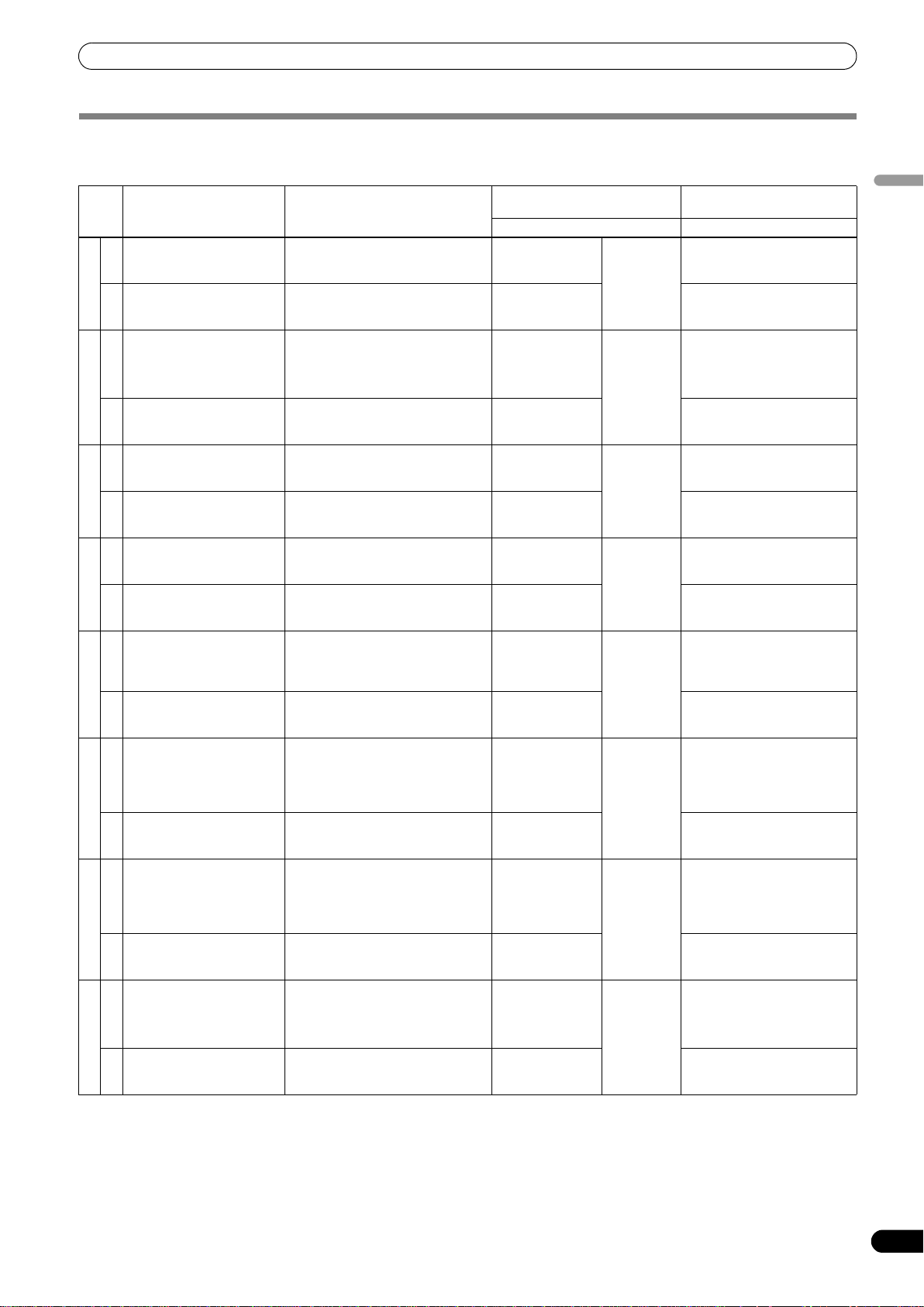
USING THE EFFECT FUNCTION
EFFECT LIST
BEAT effects (*1)
Description of the effect Beat button parameter
Repeat sound will be output
once to the beat.
AUDIO
Repeat video will be output
once to the beat.
1. DELAY (*7)
VIDEO
Sound will be output several
times to the beat as it
attenuates.
AUDIO (*2)
Video will be output several
2. ECHO (*7)
times to the beat as it
attenuates.
VIDEO
Sound sways right and left to
the beat.
AUDIO
Video sways right and left to
3. PAN
the beat.
VIDEO
Sound is cut off to the beat. For the time of 1 BPM beat, a 1/8 to
AUDIO
Video is cut off to the beat. For the time of 1 BPM beat, a 1/8 to
4. TRANS
VIDEO
Dramatically changes the
sound tone by moving the
cutoff frequency of the filter
AUDIO
in rhythm to the beat.
Outputs an opaque video to
5. FILTER
the beat.
VIDEO
One Flanger effect cycle is
quickly and simply created to
the beat.
AUDIO
FLANGER
An enlarged image of the
6.
contour of the video is output
to the beat.
VIDEO
One cycle of phaser effect is
quickly and simply created to
the beat.
AUDIO
An rotating image of the
7. PHASER
contour of the video will be
output to the beat.
VIDEO
Reverberation effect. Sets the degree of the reverberation
AUDIO (*2)
Video with an afterimage will
8. REVERB
be output.
VIDEO
For the time of 1 BPM beat, a 1/4 to
8/1 delay time will be set.
For the time of 1 BPM beat, a 1/4 to
8/1 delay time will be set.
For the time of 1 BPM beat, a 1/4 to
8/1 delay time will be set.
For the time of 1 BPM beat, a 1/4 to
8/1 delay time will be set.
For the time of 1 BPM beat, a 1/8 to
8/1 sway time (for audio) will be set.
For the time of 1 BPM beat, a 1/8 to
8/1 sway time (for video) will be set.
8/1 cut time will be set.
8/1 cut time will be set.
For the time of 1 BPM beat, a 1/2 to
32/1 time will be set for the cycle in
which the cutoff frequency is moved.
For the time of 1 BPM beat, a 1/2 to
32/1 time will be set for the cycle in
which the opaque filter is applied.
For the time of 1 BPM beat, a 1/2 to
32/1 time will be set for the interval in
which the flanger effect is moved.
For the time of 1 BPM beat, 1/2 to 32/1
time will be set for the interval in
which the effect screen appears.
For the time of 1 BPM beat, a 1/2 to
32/1 time will be set for the interval in
which the phaser effect is moved.
For the time of 1 BPM beat, 1/2 to 32/1
time will be set for the interval in
which the effect screen appears.
from between 10 % and 90 %.
Sets the degree of the afterimage
from between 10 % and 90 %.
Parameter 1
(TIME/PARAMETER)
Description Description
Sets delay time. 1 to 4 000
Sets delay time. Sets the balance between the
Sets delay time. 1 to 4 000
Sets delay time. Sets the balance between the
Sets effect time. 10 to 16 000
Sets effect time. Sets the balance between the
Sets effect time. 10 to 16 000
Sets effect time. Sets the balance between the
Sets the cycle in
which the cutoff
frequency moves.
Sets the cycle in
which the opaque
filter is applied.
Sets the interval in
which the flanger
effect moves.
Sets the interval in
which the effect
screen appears.
Sets the interval in
which the phaser
effect moves.
Sets the interval in
which the effect
screen appears.
Sets the degree of
the reverberation.
Sets the degree of
the afterimage.
(ms) (*3)
(ms) (*3)
(ms)
(ms) (*4)
10 to 32 000
(ms)
10 to 32 000
(ms)
10 to 32 000
(ms)
1 to 100 (%) Sets the balance between the
Parameter 2
(LEVEL/DEPTH)
Sets the balance between the
original sound and the delay
sound.
original video and the delay
video.
Sets the balance between the
original sound and the echo
sound.
original video and the echo
video.
Sets the balance between the
original sound and the effect
sound.
original video and the effect
video.
Sets the balance between the
original sound and the effect
sound.
original video and the effect
video.
The effect is enhanced as the
dial is rotated to the right.
Sets the balance between the
original video and the effect
video.
The effect is enhanced as the
dial is rotated to the right. Only
the original sound will be
output when the dial is rotated
completely to the left.
Sets the balance between the
original video and the effect
video.
The effect is enhanced as the
dial is rotated to the right. Only
the original sound will be
output when the dial is rotated
completely to the left.
Sets the balance between the
original video and the effect
video.
original sound and the effect
sound.
Sets the balance between the
original video and the effect
video.
English
23
En
Page 24
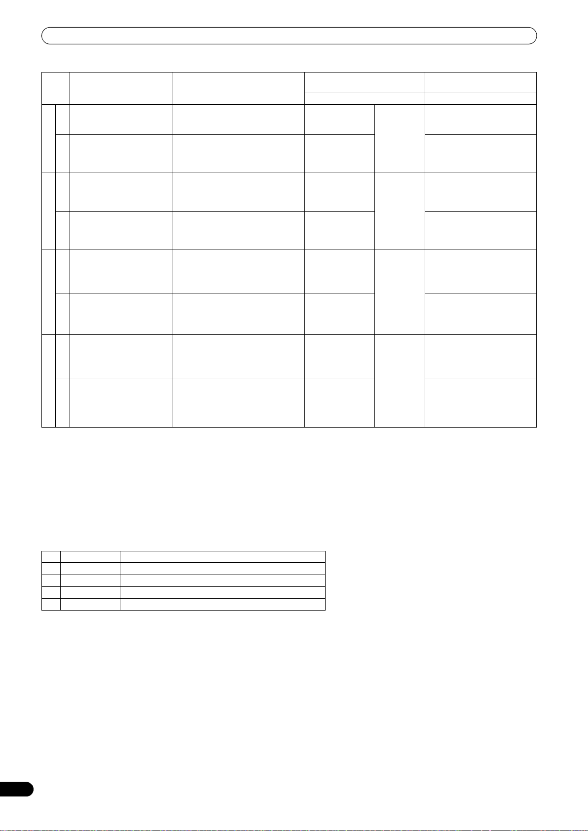
USING THE EFFECT FUNCTION
Description of the effect Beat button parameter
The input sound is given an
effect like that created by a
robot.
AUDIO
A robot-like video is created
by swinging the image up
9. ROBOT
and down and applying a
VIDEO
mosaic filter.
An expansive sound as if
various sources were
emitting the same sound
AUDIO
pitch.
A video divided into RGB
components is output to the
10. CHORUS
beat.
VIDEO
Records and repetitively
outputs the beat sound.
AUDIO (*2)
Records and repetitively
outputs the beat image.
11. ROLL (*5, 7)
VIDEO (*6)
Records and repetitively
outputs the beat sound in
reverse.
AUDIO (*2)
Records and repetitively
outputs the beat video in
reverse.
REVERSE ROLL (*5, 7)
VIDEO (*6)
12.
Sets the effect of the robotic sound
pitch between –100 % and 100 %
Sets the ratio of the mix between the
mosaic size and the original video
between –100 % and 100 %
For the time of 1 BPM beat, a 1/2 to
32/1 time will be set for the interval of
the vibrato of the chorus sound.
For the time of 1 BPM beat, a 1/2 to
32/1 time will be set for the interval in
which the image returns to the
original.
For the time of 1 BPM beat, a 1/8 to
8/1 effect time is be set.
For the time of 1 BPM beat, a 1/8 to
8/1 effect time is be set.
For the time of 1 BPM beat, a 1/8 to
8/1 effect time is be set.
For the time of 1 BPM beat, a 1/8 to
8/1 effect time is be set.
Parameter 1
(TIME/PARAMETER)
Description Description
Sets the effect of
the robotic sound
pitch.
Sets the ratio of the
mix between the
mosaic size and
the original video.
Sets the interval in
which the chorus
sound is
modulated.
Sets the interval in
which the image
returns to its
original.
Sets effect time. 10 to 4 000
Sets the time in
which the image is
repeated.
Sets effect time. 10 to 4 000
Sets the time in
which the image is
repeated.
–100 to 100
(%)
10 to 32 000
(ms)
(ms) (*3)
(ms) (*3)
Parameter 2
(LEVEL/DEPTH)
The effect is enhanced as the
dial is rotated to the right.
The up and down swinging is
enhanced as the dial is rotated
to the right.
Sets the balance between the
original sound and the chorus
sound.
Sets the balance between the
original video and the effect
video.
Sets the balance between the
original sound and the ROLL
sound.
Sets the balance between the
original video and the effect
video.
Sets the balance between the
original sound and the ROLL
sound.
Sets the balance between the
original video and the effect
video.
(*1) When the effect channel display shows [CFA], [CFB], or [MST]/[MASTER], even if the effect monitor is turned ON, if the selected
channel’s sound is not output to the master output, the effect sound will not be heard.
(*2) If effect is set to OFF, the effect sound will not be audible when monitoring effects.
(*3) The shortest video effect time value is: For NTSC, 66 ms. For PAL, 80 ms.
(*4) The shortest video effect time value is: For NTSC, 99 ms. For PAL, 119 ms.
(*5) When the visualizer function is switched from ON to OFF, the visualizer’s image will be subjected to ROLL in the sampling state.
(*6) When effects are set to OFF, images with effects applied will not be displayed on the video effects monitor.
(*7) Effects will be disabled in all channels if copy-protected contents are input to any channel. In other words, in this case effects will not
function even if non-copy-protected contents are input to the channel to which you wish to apply effects.
Video effect pattern
No. Name Description of video effect pattern
1 ORIGINAL Original image without video effect pattern.
2 INVERSE Inverts brightness.
3 EDGE Creates a border around the image.
4 HUE Changes the color (except black and white).
24
En
Page 25
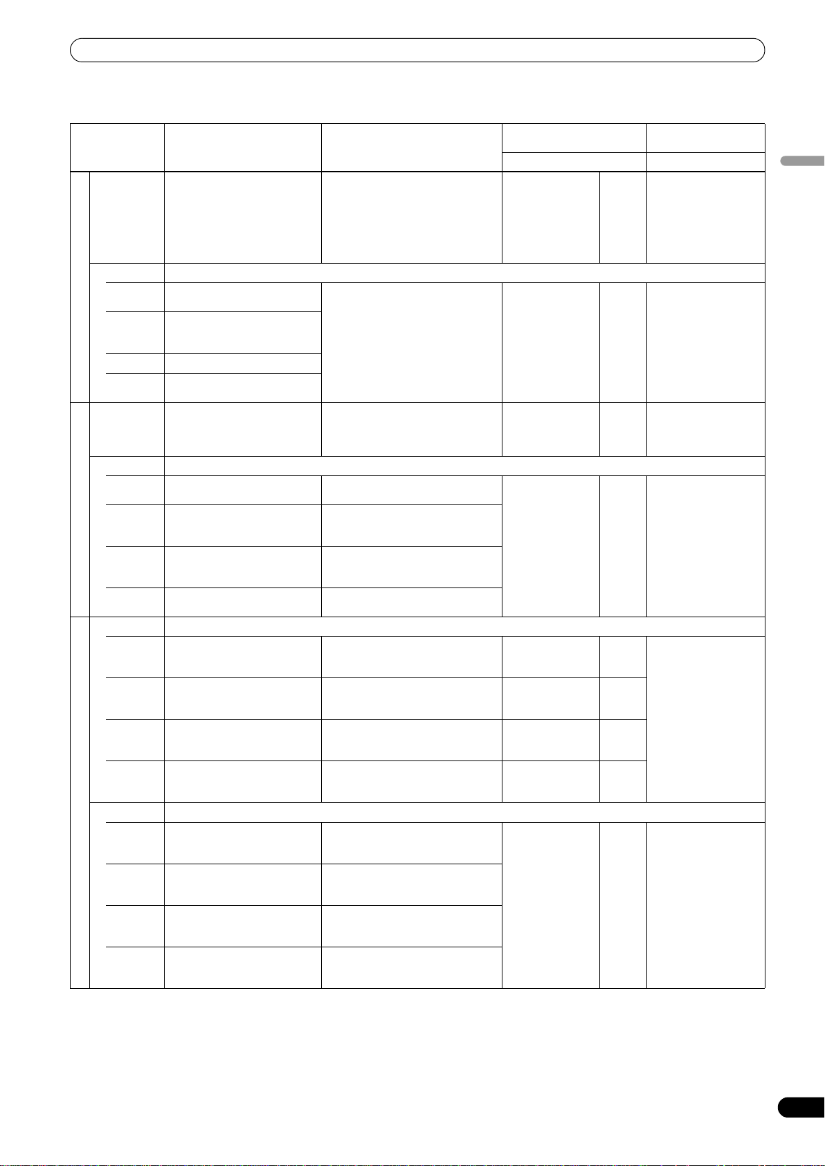
USING THE EFFECT FUNCTION
TOUCH effects (*1)
Description of the effect Description of the effect when
AUDIO Phasing effect is applied
VIDEO Outputs an effect in which ripples spread from the point being touched.
PATTERN1
1. RIPPLE (*2)
PATTERN2
PATTERN3
PATTERN4
AUDIO
(*4)
VIDEO Outputs a magnified or reduced-size image.
PATTERN1
PATTERN2
2. ZOOM (*2)
PATTERN3
PATTERN4
AUDIO Outputs a sound with the cutoff frequency of the filter changed.
PATTERN1
PATTERN2
PATTERN3
PATTERN4
VIDEO Outputs a blurred image.
3. BLUR (*2)
PATTERN1
PATTERN2
PATTERN3
PATTERN4
proportional to the volume of
the input bass sound.
Continuously outputs five
ripples.
Continuously outputs seven
ripple designs (shifts in the
brightness).
Outputs curtain-like ripples.
Continuously outputs three
large ripples.
Outputs a reverberation effect. Touch the screen toward the right to
Outputs an image zoomed in on
the point touched.
Outputs an image stretched
horizontally from the point
touched.
Outputs an image stretched
vertically from the point
touched.
Outputs an image zoomed out
from the point touched.
Outputs a sound through a lowpass filter.
Outputs a sound through a
high-pass filter.
Outputs a sound through a
band-pass filter.
Outputs a sound through a
notch filter.
Outputs an image with blur
toward the left side.
Outputs an image with blur
toward the right side.
Outputs an image with blur
toward the bottom side.
Outputs an image with blur
toward the top side.
touched
Touch the screen toward the right to
enhance the effect. Touch toward
the left to reduce the effect.
Outputs an effect in which ripples
spread from the point being
touched.
enhance the effect. Touch toward
the left to reduce the effect.
Outputs an image zoomed in on the
point touched.
Outputs an image stretched
horizontally from the point touched.
Outputs an image stretched
vertically from the point touched.
Outputs an image zoomed out from
the point touched.
Touch the screen toward the right to
enhance the effect. Touch toward
the left to reduce the effect.
Touch the screen toward the right to
enhance the effect. Touch toward
the left to reduce the effect.
Touch the screen toward the right to
enhance the effect. Touch toward
the left to reduce the effect.
Touch the screen toward the right to
enhance the effect. Touch toward
the left to reduce the effect.
Touch more toward the right to
enhance the blurred effect on the left
side.
Touch more toward the right to
enhance the blurred effect on the
right side.
Touch more toward the right to
enhance the blurred effect on the
bottom side.
Touch more toward the right to
enhance the out-of-focus effect on
the top side.
Parameter 1
(TIME/PARAMETER)
Description Description
– – Rotate the dial
Sets the strength
(the amplitude) of
the ripples.
– – Sets the balance
Sets the scale of
magnification/redu
ction.
–––
––
––
––
Sets color when
blur effect is
applied.
1 to 10 Sets the balance
1 to 10 Sets the balance
1 to 10 Sets the balance
Parameter 2
(LEVEL/DEPTH)
clockwise to enhance
the effect. When dial is
rotated fully
counterclockwise, only
original sound is
output.
between the original
video and the effect
video.
between the original
sound and the effect
sound.
between the original
video and the effect
video.
between the original
video and the effect
video.
English
25
En
Page 26
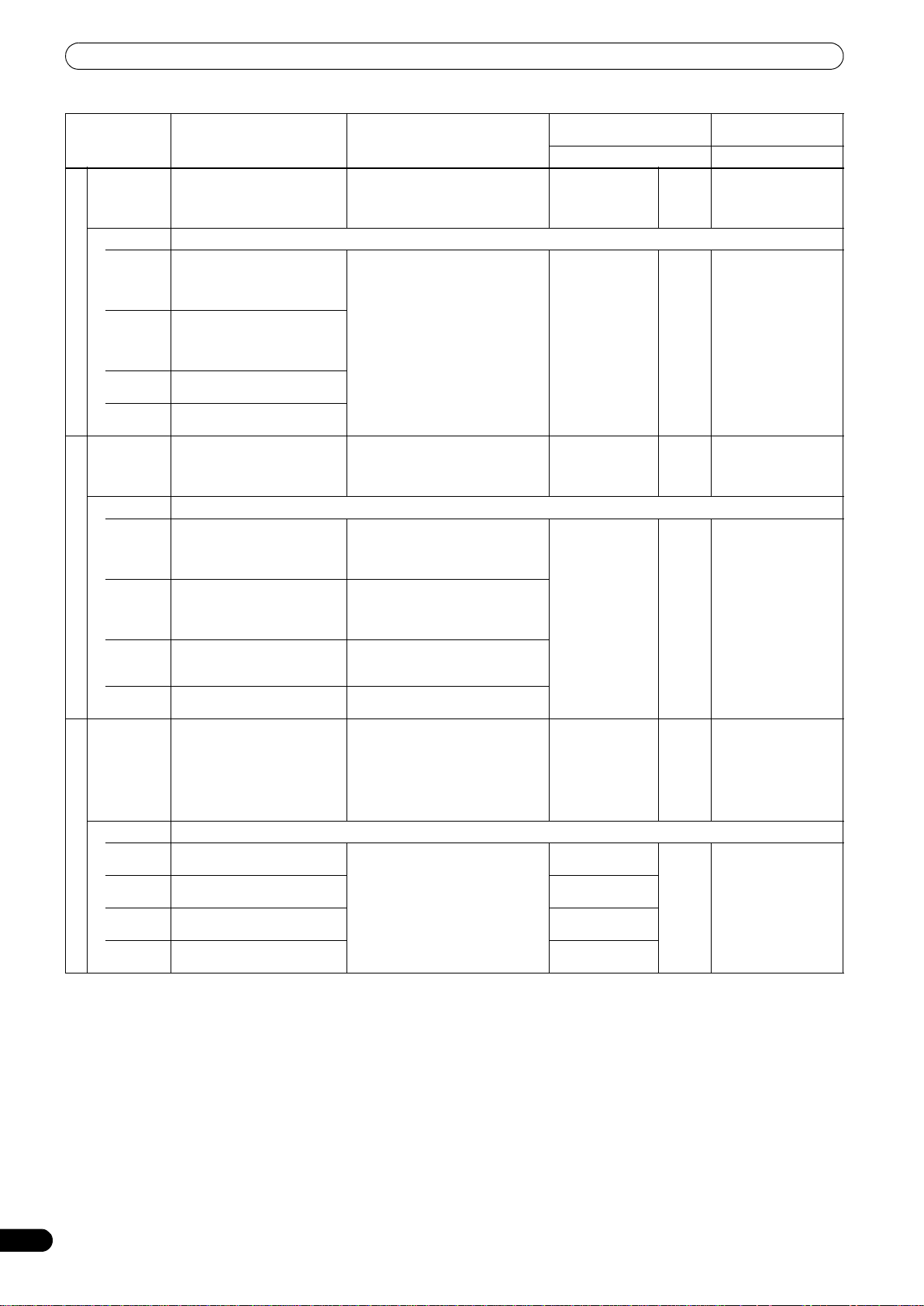
USING THE EFFECT FUNCTION
Description of the effect Description of the effect when
AUDIO
(*4)
VIDEO Outputs an image with a warping effect.
PATTERN1
PATTERN2
4. DISTORTION (*2)
PATTERN3
PATTERN4
AUDIO Modulates the input sound. The
VIDEO Outputs an images lined in blocks.
PATTERN1
PATTERN2
5. BLOCK
PATTERN3
PATTERN4
AUDIO Outputs audio as if the input
VIDEO Outputs an image with a radial concentric effect.
PATTERN1
6. RADIATION
PATTERN2
PATTERN3
PATTERN4
Outputs a phaser effect with
reverberation.
Outputs an image in which the
screen warps with the
appearance of paint mixed with
water.
Outputs an image with effect
applied like pixelation distortion
from the point the screen is
touched.
Outputs an image with
fragmented warp.
Outputs an image with spiral
warp.
bass sound has a metallic
quality.
Outputs an image in which the
touched block stretches and
shrinks in the horizontal and
vertical direction.
Outputs an image in which the
touched block stretches and
shrinks in the horizontal
direction.
Outputs an image in which the
touched block stretches and
shrinks in the vertical direction.
Outputs an image in which the
touched block changes color.
sound has been crushed.
Outputs an image that appears
like a light shining from behind.
Outputs an image that spreads
radially.
Outputs an image of circles
spreading concentrically.
Outputs an image combining
PATTERN 2 and PATTERN 3.
touched
Touch more toward the right to
increase the length of the phaser
effect cycle. Touch toward the left for
shorter cycle length.
The warp effect is applied centering
on the touched point. The longer you
touch the screen, the stronger the
effect becomes.
Touch the screen toward the right to
enhance the effect. Touch toward
the left to reduce the effect.
Outputs an image in which the
touched block stretches and shrinks
in the horizontal and vertical
direction.
Outputs an image in which the
touched block stretches and shrinks
in the horizontal direction.
Outputs an image in which the
touched block stretches and shrinks
in the vertical direction.
Outputs an image in which the
touched block changes color.
Touch the screen toward the right to
enhance the effect. Touch toward
the left to reduce the effect.
The touched location will have the
central coordinates of the effect.
Parameter 1
(TIME/PARAMETER)
Description Description
– – Sets the balance
Sets the area in
which the effect is
applied.
– – Sets the balance
Sets the number of
partitions of the
blocks.
– – Rotate the dial
Sets the color. 1 to 10 Sets the balance
Sets the opening of
the center.
Sets the opening of
the center.
Sets the opening of
the center.
1 to 10 Sets the balance
1 to 10 Sets the balance
Parameter 2
(LEVEL/DEPTH)
between the original
sound and the effect
sound.
between the original
video and the effect
video.
between the original
sound and the effect
sound.
between the original
video and the effect
video.
clockwise to enhance
the effect. When dial is
rotated fully
counterclockwise, only
original sound is
output.
between the original
video and the effect
video.
26
En
Page 27
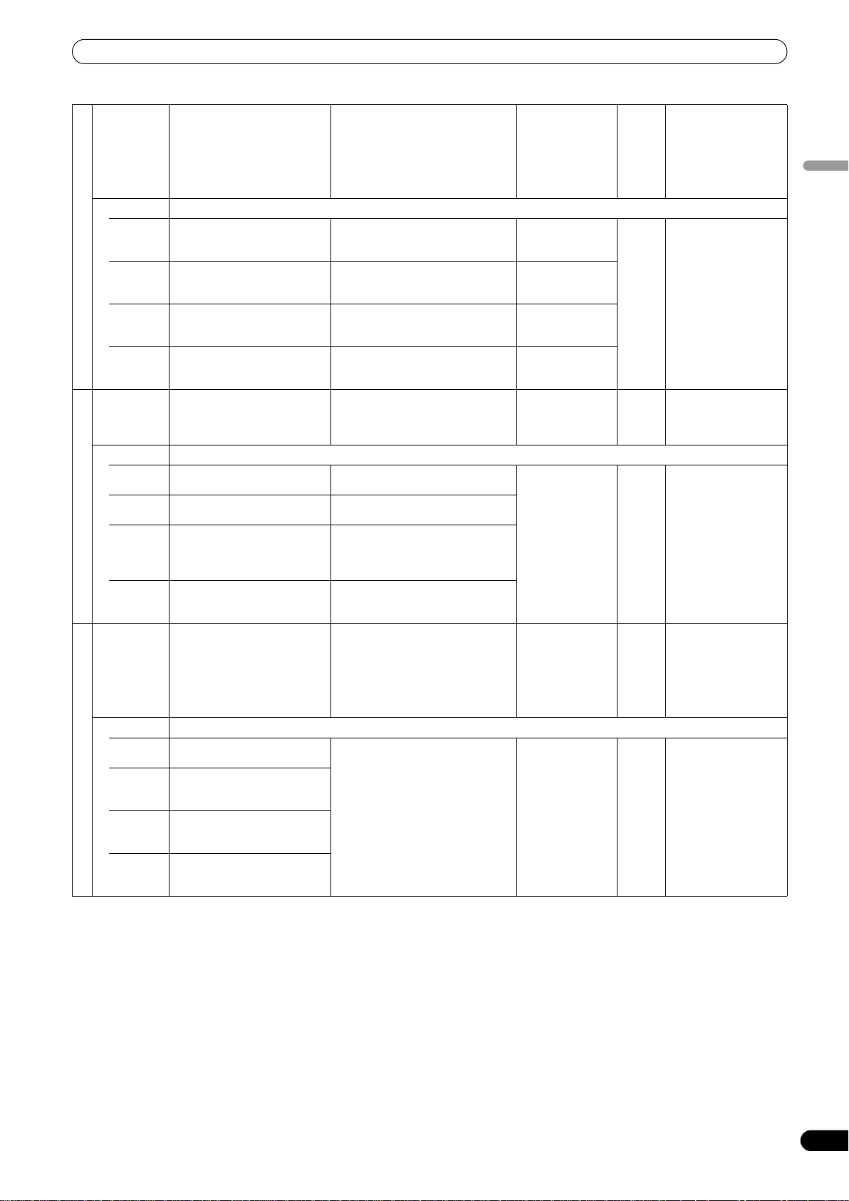
USING THE EFFECT FUNCTION
AUDIO Outputs the input sound as if it
VIDEO Outputs a kaleidoscope-like effect.
PATTERN1
PATTERN2
7. KALEIDO
PATTERN3
PATTERN4
AUDIO Produces an effect that lowers
VIDEO Outputs image with a lens-like effect.
PATTERN1
PATTERN2
8. LENS
PATTERN3
PATTERN4
AUDIO Produces phaser effect. By
VIDEO Outputs an image formulated as a cube.
PATTERN1
PATTERN2
9. CUBE
PATTERN3
PATTERN4
were being made by a robot.
Outputs an image circularly
dividing the screen from the
center of the screen.
Outputs an image horizontally
dividing the screen (vertically
stacked).
Outputs an image vertically
dividing the screen (arranged
horizontally).
Outputs an image divided
horizontally and vertically.
the pitch of the input sound.
Outputs image with a lens-like
effect.
Outputs image with a lens-like
effect.
Outputs image with a lens-like
effect.
Inverts the luminance
components, and outputs the
image with a lens-like effect.
moving the touched position
between left and right, the
volume of the effect changes.
Outputs an image of the cube
rotating.
Outputs an image of a
bottomless pyramid prism
rotating.
Outputs an image of a
bottomless pentagon prism
rotating.
Outputs an image of a
bottomless heptagon prism
rotating.
Touch more toward the right to
increase the pitch. Touch toward the
left to lower the pitch.
When the original image is touched
and moved, the screen is divided
circularly and output.
When the original image is touched
and moved, the screen is divided
horizontally (vertically stacked).
When the original image is touched
and moved, the screen is divided
vertically (arranged horizontally).
When the image is touched and
moved, the screen is divided
horizontally and vertically.
Touch the screen toward the right to
enhance the effect. Touch toward
the left to reduce the effect.
The lens moves to the location that is
touched.
The lens moves to the location that is
touched.
The lens moves to the location that is
touched, and the image within the
lens also moves in accordance with
the amount of lens movement.
The lens moves to the location that is
touched.
Touch the screen toward the right to
enhance the effect. Touch toward
the left to reduce the effect.
Moves to the touched position. Sets the size of the
– – Rotate the dial
Sets the center
angle of the image.
Sets the height of
the image.
Sets the width of
the image.
Sets the width and
height of the
image.
– – Sets the balance
Sets the size of the
lens.
– – Rotate the dial
object.
1 to 10 Sets the balance
1 to 10 Sets the balance
1 to 10 Sets the balance
clockwise to enhance
the effect. When dial is
rotated fully
counterclockwise, only
original sound is
output.
between the original
video and the effect
video.
between the original
sound and the effect
sound.
between the original
video and the effect
video.
clockwise to enhance
the effect. When dial is
rotated fully
counterclockwise, only
original sound is
output.
between the original
video and the effect
video.
English
27
En
Page 28
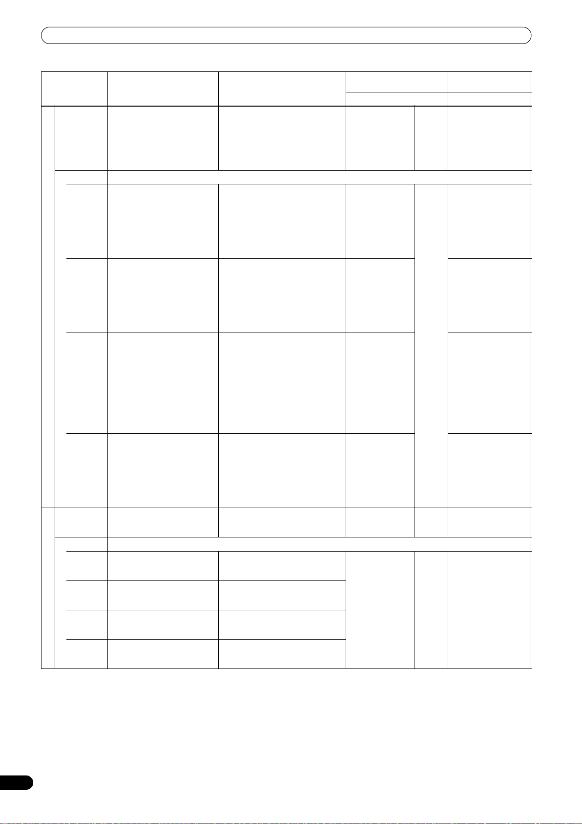
USING THE EFFECT FUNCTION
Description of the effect Description of the effect when
AUDIO Flanger effect is applied. Move
VIDEO Outputs an image with a twisting rotational effect.
PATTERN1
PATTERN2
10. TWIST
PATTERN3
PATTERN4
AUDIO Outputs a sound with the cutoff
VIDEO Outputs image with a spotlight effect.
PATTERN1
PATTERN2
11. SPOT (*3)
PATTERN3
PATTERN4
finger on touch panel to rightleft to change effect volume.
Outputs an image in which the
screen twists and rotates.
Outputs an image where the
screen is divided and twisted
individually.
As in PATTERN2, the screen
image is divided, and in
proportion to the audio level,
the image is stretched and
compressed like a graphic
equalizer effect.
Outputs an image where the
screen is twisted and an
afterimage is left.
frequency of the filter changed.
Outputs image with a spotlight
of a random size on a random
location.
Outputs image with a spotlight
of a random size on a random
location.
Outputs an image with a
spotlight of a random size and
color on a random location.
Outputs an image with a
spotlight of a random size and
color on a random location.
touched
Touch more toward the right to
lengthen the cycle of the flanger
effect. Touch toward the left for
shorter effect cycle.
The image rotates when you touch
and drag your finger in a circular
motion around the center of the
screen.
The image rotates when you touch
and drag your finger in a circular
motion around the center of the
screen.
The block of the touched location
will stretch. While touching, the
stretching and shrinking
correspondent to the audio level will
stop.
The image rotates when you touch
and drag your finger in a circular
motion around the center of the
screen.
Touch the screen toward the right to
enhance the effect. Touch toward
the left to reduce the effect.
Outputs an image with a spotlight of
a fixed size on the touched location.
Outputs an image with a spotlight of
a random size on the touched
location.
Outputs an image with a spotlight of
a fixed size and random color on the
touched location.
Outputs an image with a spotlight of
a random size and color on the
touched location.
Parameter 1
(TIME/PARAMETER)
Description Description
– – Rotate the dial
Sets the twisting
speed.
Set the number of
divisions.
Set the number of
divisions.
Sets the twisting
speed.
– – Rotate dial clockwise to
Sets the interval in
which the spotlight
is updated.
1 to 10 Sets the balance
1 to 10 Sets the balance
Parameter 2
(LEVEL/DEPTH)
clockwise to enhance
the effect. When dial is
rotated fully
counterclockwise, only
original sound is
output.
between the original
video and the effect
video.
When enlarged more
than the center, the
rotating speed
increases.
Sets the balance
between the original
video and the effect
video.
When enlarged more
than the center, the
rotating speed
increases.
Sets the balance
between the original
video and the effect
video.
When enlarged more
than the center, the
shrinking speed
decreases, and as MAX
is approached,
changes to the reverse,
stretching operation.
Sets the balance
between the original
video and the effect
video.
When enlarged more
than the center, the
rotating speed
increases.
enhance effect.
between the original
video and the effect
video.
28
En
Page 29

USING THE EFFECT FUNCTION
AUDIO Flanger effect is applied. Move
VIDEO Outputs an image of a circle with color in motion.
PATTERN1
12. DROP (*3)
PATTERN2
PATTERN3
PATTERN4
finger on touch panel to rightleft to change effect volume.
Outputs an image of a circle
with dot designs.
Outputs an image of a circle
with border designs.
Outputs an image of a circle
with vertically stretched image.
Outputs an image of a circle
with original image.
Touch more toward right side to
enhance effect. Touch more toward
left side to decrease effect.
The circle moves towards the
touched point.
– – Rotate the dial
Sets the size of the
circle.
1 to 10 Sets the balance
clockwise to enhance
the effect. When dial is
rotated fully
counterclockwise, only
original sound is
output.
between the original
video and the effect
video.
(*1) When the [HOLD] button is set to ON, you can record the track of your finger touching the touch panel for a maximum of 8 seconds.
(*2) The effect will not become visible unless the video effect performance monitor is touched.
(*3) When effect is set to ON, random effects are applied.
(*4) When effect is set to OFF, effect sounds cannot be heard even on monitor.
English
29
En
Page 30
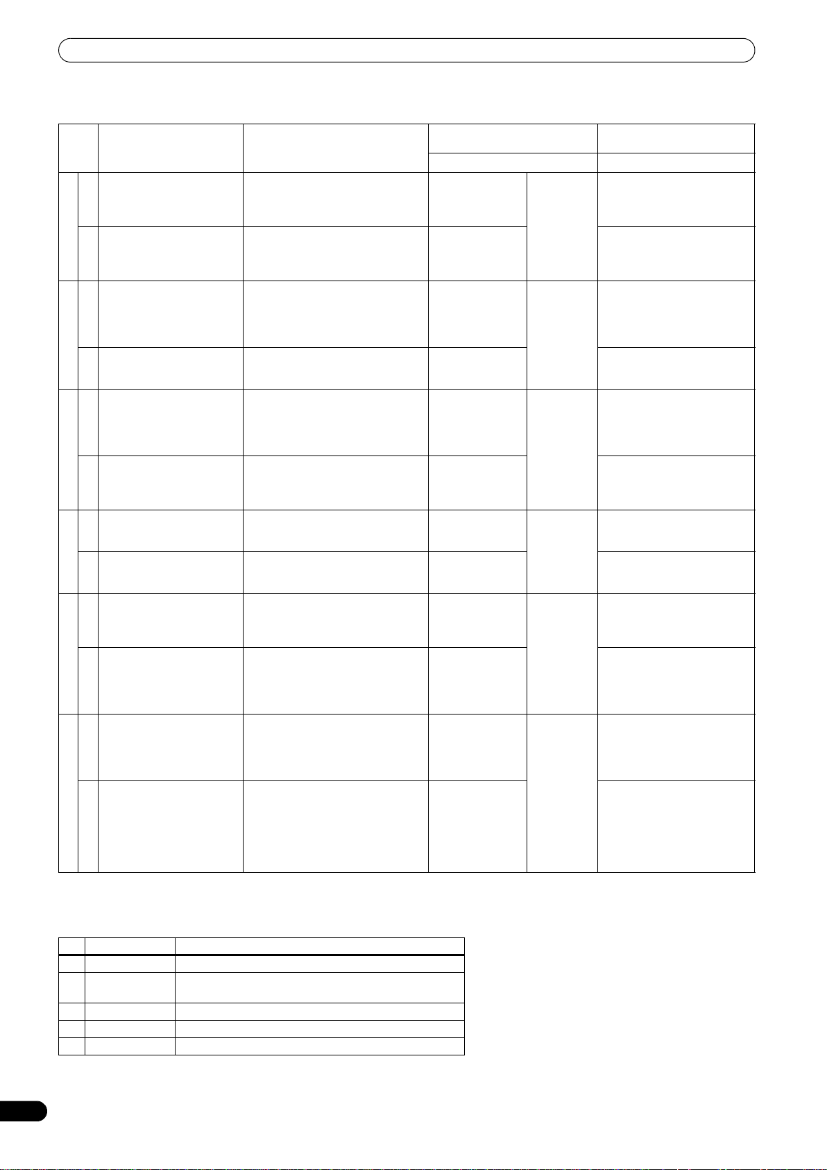
USING THE EFFECT FUNCTION
TEXT effects
Parameter 1
Description of the effect Beat button parameters
Dramatically changes the
sound tone by moving the
frequency of the filter in
AUDIO
rhythm to the beat.
The text line chips away at
dot block units and then
1. BLOCK
reconstructs itself at dot
VIDEO
block units.
One phaser effect cycle is
quickly and simply created to
the beat.
AUDIO
The text line is lines up and
2. ROTATION
forms a circle as it rotates.
VIDEO
One Flanger effect cycle is
quickly and simply created to
the beat.
AUDIO
The text string will glow and
3. SLIDE
stretch out horizontally in a
linked manner, and then
VIDEO
return to the original string.
Cuts the sound in rhythm to
the beat.
AUDIO
Random text lines appear. For the time of 1 BPM beat, a 1/8 to
4. RANDOM
VIDEO
Outputs audio in which the
input sound starts from a
high pitch and returns to its
AUDIO
normal sound.
Beginning from zoom-in on
each individual letter, a text
5. ZOOM
string is formed as the letters
zoom out to their set
VIDEO
positions.
Outputs audio as if the input
sound has been crushed.
AUDIO
From the first letter of the text
string, the letters become
stretched from left to right as
6. CRUSH
they appear, and from the
first letter of the text line, the
VIDEO
letters are stretched from
right to left as they disappear.
For the time of 1 BPM beat, a 1/2 to
32/1 time will be set for the interval in
which the cutoff frequency is moved.
For the time of 1 BPM beat, a 1/2 to
32/1 time is set for which the text
disappears at dot block units and
then reconstructs itself again.
For the time of 1 BPM beat, a 1/2 to
32/1 time will be set for the interval in
which the phaser effect is moved.
For the time of 1 BPM beat, a 1/2 to
32/1 time is set for which the text
rotates once.
For the time of 1 BPM beat, a 1/2 to
32/1 time is set for the interval in
which the flanger effect is moved.
For the time of 1 BPM beat, a 1/2 to
32/1 time will be set in which the text
begins to change and then returns to
its original state again.
For the time of 1 BPM beat, a 1/8 to
8/1 cut time will be set.
8/1 time will be set for appearance of
random text lines.
For the time of 1 BPM beat, a 1/8 to
8/1 effect time will be set.
For the time of 1 BPM beat, a 1/8 to
8/1 time is set for which the letters
zoom out to their set positions.
For the time of 1 BPM beat, a 1/2 to
32/1 time will be set for the interval in
which the crush effect is moved.
For the time of 1 BPM beat, a 1/2 to
32/1 time is set for which the text
appears as it is stretched, and then
disappears as it is stretched.
(TIME/PARAMETER)
Description Description
Sets the interval for
which the cutoff
frequency moves.
Sets effect time. Sets the balance between the
Sets the interval in
which the phaser
effect moves.
Sets effect time. Sets the balance between the
Sets the interval for
which the flanger
effect moves.
Sets effect time. Sets the balance between the
Sets effect time. 10 ms to
Sets effect time. Sets the balance between the
Sets effect time. 10 ms to
Sets effect time. Sets the balance between the
Sets the interval for
which the crush
effect moves.
Sets effect time. Sets the balance between the
10 ms to
32 000 ms
10 ms to
32 000 ms
10 ms to
32 000 ms
16 000 ms
16 000 ms
10 ms to
32 000 ms
(*1) Video effects are dependant upon image display timing, with the result that an effect may not appear precisely as intended when the
set time is very short.
Character
Parameter 2 (LEVEL/DEPTH)
Rotate dial clockwise to
enhance effect.
original video and the text.
Rotate the dial clockwise to
enhance the effect. When dial
is rotated fully
counterclockwise, only original
sound is output.
original video and the text.
Rotate the dial clockwise to
enhance the effect. When dial
is rotated fully
counterclockwise, only original
sound is output.
original video and the text.
Sets the balance between the
original sound and the effect
sound.
original video and the text.
Sets the balance between the
original sound and the effect
sound.
original video and the text.
Rotate the dial clockwise to
enhance the effect. When dial
is rotated fully
counterclockwise, only original
sound is output.
original video and the text.
30
En
No. Name Description of character
1 ORIGINAL Sets text alone, without reflecting the character.
2 SHADOW Applies shadow to displayed text. When COLOR is B/W,
both will have the same effect.
3 TRANSPARENT Makes text transparent.
4 OUTSIDE Applies border to text.
5HUE Changes color of text (except when black and white).
Page 31

USING THE JPEG VIEWER
1
3
2
USING THE JPEG VIEWER
JPEG files can be loaded and displayed from USB memory devices and SD cards. Up to eight JPEG files can be loaded.
USB
HI
JPEG
VIEWER
10
10
9
9
8
8
7
7
6
6
5
5
4
4
3
3
2
2
1
1
0
0
CARD indicator
BEFORE USING THE JPEG VIEWER
Insert a USB memory device or SD card into this mixer.
SD
CARD
JPEG VIEWER SETUP
1 Press the JPEG VIEWER button.
The JPEG play mode screen will appear.
9
1
2
3
5
English
7
4
8
Using a USB memory device
Insert a USB memory device containing JPEG files to the USB
connector. Only USB memory devices formatted in FAT32 format
can be used.
Using a SD card
Insert a SD card containing JPEG files into the SD CARD slot.
• The memory card used must be formatted according to “SD
Memory Card Specifications Part2 FILE SYSTEM
SPECIFICATION Version1.0” (SD memory cards are formatted in
the aforementioned standard upon shipping from their
manufacturers). Unformatted memory cards cannot be used.
• Memory cards formatted on computers or digital cameras may
not operate properly.
•Multi-media cards (MMC) cannot be used.
• Do not remove the card or turn the power off while the CARD
indicator is blinking (doing so may result in damage to the
stored data).
• Memory cards are delicate electronic devices. Do not bend
them, subject them to strong shocks or impacts. Additionally,
do not use or store memory cards in environments likely to
create static electricity or electrical noise.
• Memory cards may be damaged when exposed to impacts or
static electricity. Handle them with care. It is strongly suggested
that you periodically make copies of important data.
• Pioneer will not be held responsible for any loss of data or direct/
indirect damages.
6
1 [MANUAL
MODE] button
2 [AUTO MODE]
button
3 [FADER MODE]
button
4 [TIME] display/
Change buttons
5[JPEG BOX]
6 Channel select
buttons
7 [JPEG SELECT]
button
8 [CLEAR] button
9 [EXIT] button
Sets the JPEG play mode to MANUAL.
Sets the JPEG play mode to AUTO.
Sets the JPEG play mode to FADER.
When in AUTO mode, sets the time for
changing the JPEG images.
Selects the JPEG images that are to be
assigned to the channels.
Sets the channel to which JPEG images
are to be assigned.
Alternatively use to cancel the assigned
JPEG.
Enables JPEG select mode.
If operated when effects are ON, a
warning message will appear and the
screen will not change to the next menu.
Alternates JPEG BOX clear mode ON/
OFF.
Exits JPEG viewer setup.
31
En
Page 32

USING THE JPEG VIEWER
8
8
8
Loading JPEG files to the SVM-1000
Use this function to load JPEG files into the JPEG BOX. When
effect is ON, this function is not usable.
1 Touch the [JPEG SELECT] button in the JPEG play mode
screen.
The JPEG select mode screen will appear.
7
2
4
1
1 Media/folder/
file display
2 Address display
3 Page display/
Page change
buttons
4 [BACK] button
5[JPEG BOX]
6 [CLEAR] button
7 [EXIT] button
Displays media, files, and folders.
Displays the address of the media/
folders/files currently being displayed.
Advances the page display of the
displayed media/folder/file.
Returns to the next higher level of the
folder hierarchy.
Selects the JPEG BOX into which the
JPEG is to be loaded.
Alternates the JPEG BOX clear mode ON/
OFF.
Exits JPEG viewer mode and returns to
JPEG play mode.
Using a JPEG file by assigning it to a channel.
The JPEG play mode includes MANUAL MODE, AUTO MODE, and
FADER MODE, allowing a wide range of performance styles.
Operating in MANUAL MODE
Assign JPEG image in JPEG BOX as image for designated
channel.
1 Touch the [MANUAL MODE] button to select MANUAL mode.
2 From the JPEG BOX, select the image you wish to assign.
When an image is touched, the border around the image will
change to white.
3 Select the channel to which you wish to assign the image.
3
6
5
Touch the channel select button for the channel you wish to
assign the image to, and the selected image will be displayed
on the channel monitor. In this condition, the JPEG image can
be treated as the input image for that channel.
• When the channel select button is ON, touching one of the
other images in the JPEG BOX will cause the display to
switch instantly to that image.
• When a channel select button is ON, touching one of the
other channel select buttons causes the assigned channel
to be changed instantly.
• A JPEG image can be assigned only to one channel selected
with the channel select button.
• If the channel select button is touched again, the
assignment is canceled.
Operating in AUTO MODE
A slide show program can be created in which images in the JPEG
BOX change automatically, and the slide show can be assigned to
a designated channel.
1 Touch the [AUTO MODE] button to select AUTO mode.
2 From the JPEG BOX, select the images you wish to use.
Touch the multiple images you wish to use, and their borders
will turn to white. Touching an image again will deselect it.
3 Select the channel to which you wish to assign the images.
Touch the channel select button for the desired channel and
the slide show of selected multiple images will be displayed on
the channel monitor. In this condition, the slide show can be
treated as the input image for that channel.
4 Use the [TIME] change button to adjust the transition time
for the slide show.
2 Select a JPEG file you wish to download from the media/
folder/file display.
The media/folder/file display will start from the media used
(USB memory/SD card).
Only JPEG files will be displayed.
Displayable folders and JPEG files are in alphabetical order,
with a maximum 64 folders and 192 files per hierarchical level.
3 Touch the [JPEG BOX] to download the file.
4 Touch the [EXIT] button to end the JPEG viewer mode and
return to JPEG play mode (P. 31).
• When power is turned OFF, JPEG images read into the unit
will be deleted.
32
En
Page 33

USING THE JPEG VIEWER
Operating in FADER MODE
Using the JPEG images in the JPEG BOX, a slide show can be
created with transitions between images at chosen intervals. The
channel fader for the assigned channel is used to perform the
transitions.
1 Touch the [FADER MODE] button to select FADER mode.
2 Select the images you wish to use from the JPEG BOX.
Touch multiple images on the screen and their borders will
change to white. Touch again to deselect images.
3 Select the channel to which you wish to assign the images.
Touch the channel select button for the channel to which you
wish to assign the images, and the image at the upper left of
the group of selected images will be displayed on the channel
monitor.
4 Operate the fader.
Each time the channel fader for the assigned channel is raised
from the [0] point, the images will change.
Deleting JPEG files downloaded to the JPEG BOX
1 Touch the [CLEAR] button.
The [CLEAR] button will flash.
2 Touch the images on the screen that you wish to delete.
The instant the image is touched, it disappears from the JPEG
BOX. While the [
by deleting other images if desired.
• This process does not affect file data on attached SD cards
or USB memory devices.
3 Press the [CLEAR] button once again to leave this mode.
• Usable JPEG files have a maximum size of 7 MB or about 12
MP.
• If the original JPEG file does not fit within 640 x 480 pixels,
the file will be automatically resized to 640 x 480 pixels when
downloaded to the SVM-1000.
CLEAR
] button is flashing, you may continue
English
33
En
Page 34

THE VIDEO EQUALIZER FUNCTION
THE VIDEO EQUALIZER FUNCTION
Rotating the channel equalizer dial normally applies equalizer effects on audio only. However, by using the VIDEO EQ function, effects
can be applied to video as well.
VIDEO EQ
HI
10
10
9
9
8
8
7
7
6
6
5
5
4
4
3
3
2
2
1
1
0
0
SET UP THE VIDEO EQ
1 Hold down the VIDEO EQ button.
This initiates the equalizer setup mode.
2 Touch each applicable button.
Touch each applicable button on the screen to operate the
VIDEO EQ setup.
• Whenever power is first turned on, default settings are as
follows:
HI: CONTRAST
MID: HUE
LOW: SATURATION
Whenever power is turned OFF, the unit returns to the above
status.
• Identical parameter values cannot be allocated to HI, MID
and LOW.
VIDEO EQ SET UP Use to make the video effects change
simultaneously when using the equalizer.
OFF: Disables the VIDEO EQ.
R: Used when assigning parameters that
change the red elements of the VIDEO
EQ.
Used when assigning parameters.
G: Used when assigning parameters that
change the green elements of the VIDEO
EQ.
Used when assigning parameters.
B: Used when assigning parameters that
change the blue elements of the VIDEO
EQ.
CONTRAST: Used when assigning
parameters that change the contrast of
the VIDEO EQ.
HUE: Used when assigning parameters
that change the hue of the VIDEO EQ.
SATURATION: Used when assigning
parameters that change the saturation of
the VIDEO EQ.
3Touch [EXIT].
This ends the equalizer setup mode.
TURNING THE EQUALIZER ON/OFF
1 Press the VIDEO EQ button.
The VIDEO EQ settings will alternate between enabled/
disabled each time the button is pressed.
34
En
Page 35

FADER START FUNCTION
FADER START FUNCTION
By connecting the optional Pioneer DJ/VJ DVD Player or DJ CD Player control cable, the channel fader and cross fader can be used to
start DVD/CD playback.
When the mixer’s channel fader lever or cross fader lever are moved, the DVD/CD player is released from the pause mode and
automatically –and instantly – begins playback of the selected track. Also, when the fader lever is returned to its original position, the DVD/
CD player returns to its cue point (back cue), thus allowing “sampler” type play.
Using the Cross Fader to Start Playback
1 Press the FADER START button for the channel (1 to 4)
connected to the DVD/CD player you wish to control.
HI
FADER
START
10
10
9
9
8
8
7
7
6
6
5
5
4
4
3
3
2
2
1
1
0
0
CHANNEL
FADER
CROSS
FADER
ASSIGN
Cross fader lever (A/B)
CROSS FADER START PLAY AND BACK
CUE PLAY
When the DVD/CD player assigned to cross fader channel A is set
to standby at a cue point, moving the cross fader lever from the
right (B) side toward the left (A) side automatically starts play on
the channel A DVD/CD player.
When the cross fader lever reaches the left (A) side, the DVD/CD
player assigned to channel B goes to back cue (returns to cue
point). Also, when the DVD/CD player assigned to channel B is set
to standby at a cue point, moving the cross fader lever from the left
(A) side to the right (B) side automatically starts playback on the
channel B DVD/CD player. When the cross fader lever reaches the
right (B) side, the DVD/CD player assigned to channel A goes to
back cue (returns to cue point).
• The button for the selected channel lights.
2 Set the CROSS FADER ASSIGN switch for the selected channel
to [A] or [B].
• Select [A] to assign to cross fader channel A (left side).
B
• Select [
] to assign to cross fader channel B (right side).
3 Move the cross fader lever to the full opposite side away
from the DVD/CD player you wish to start.
4 Set the DVD/CD player to the desired cue point, and engage
cue point standby.
• If a cue point has already been set, it is not necessary to set
the DVD/CD player to standby at the cue point.
5 At the instant you wish to start playback, move the cross
fader lever (A/B).
• DVD/CD player begins playback.
• After playback has begun, if the cross fader lever is moved
fully to the opposite side, the DVD/CD player assigned to the
opposite side channel will return to the cue point and enter
standby mode (back cue).
English
Using the Channel Fader to Start Playback
1 Press the FADER START button for the channel (1 to 4)
connected to the DVD/CD player you wish to control.
• The button for the selected channel lights.
2 Set the channel fader lever to [0].
3 Set the DVD/CD player to the desired cue point, and engage
cue point standby.
• If a cue point has already been set, it is not necessary to set
the DVD/CD player to standby at the cue point.
4 At the instant you wish to start playback, move the channel
fader lever.
• DVD/CD player begins playback.
• After playback has begun, if the channel fader lever is
returned to the [
cue point and re-enters standby mode (back cue).
• Playback control is possible with the channel fader only with
the CROSS FADER ASSIGN switch is set to [THRU].
0
] position, the DVD/CD player returns to the
35
En
Page 36

PERFORM UTILITY SETUP
PERFORM UTILITY SETUP
Set up MIDI
1 Hold the UTILITY (SET UP) button depressed.
UTILITY
(SET UP)
HI
10
10
9
9
8
8
7
7
6
6
5
5
4
4
3
3
2
2
1
1
0
0
When power is turned OFF, all utility setup values other than MIDI
CHANNEL and KEYBOARD LANGUAGE revert to their default
values.
MIDI SETTINGS
MIDI is an acronym for “Musical Instrument Digital Interface” and
refers to a protocol developed for the exchange of data between
electronic instruments and computers.
A MIDI cable is used to connect components equipped with MIDI
connectors to enable the transmission of data.
The SVM-1000 will use the MIDI function to send operational
information for hardware and BPM (timing clock).
The MIDI setup mode will be initiated.
2 Touch [MIDI].
The MIDI setup screen will be displayed.
3 Touch each applicable button.
Touch each applicable button on the screen to operate the
MIDI setup.
4Touch [EXIT].
This will end the MIDI setup mode.
SYNCHRONIZING AUDIO SIGNALS TO
EXTERNAL SEQUENCER, OR USING
SVM-1000 INFORMATION TO OPERATE
AN EXTERNAL SEQUENCER
1 Connect the DIN connector to a MIDI sequencer, and the USB
port to your computer.
This unit is equipped with both DIN type and USB type output
connectors.
• Supported operating systems include Windows Vista,
Windows XP or Mac OSX.
• For details regarding computer setup, refer to the
instruction manual for your computer and operating system.
For application setup instructions, refer to the instruction
manual for the application involved.
• Set the MIDI sequencer’s synch mode to “Slave”.
• MIDI sequencers that do not support MIDI timing clock
cannot be synchronized.
• Synch may not be achieved if the track’s BPM cannot be
detected and measured stably.
• BPM values set with the TAP mode can also be used to
output the timing clock.
2 Set the MIDI OUT to ON in the MIDI setup.
• The output range of the MIDI timing clock is 40 BPM to 250
BPM.
Note:
The BPM may not be measured correctly with some tracks.
Synchronize the computer application to the audio
signals, or operate the computer application using
the operation data for the SVM-1000.
1 Connect the USB MIDI output connector of the SVM-1000 to
your computer using the USB cable.
• Perform the MIDI settings for the application program. For
further information, refer to the instruction manual for
application program.
• Supported operating systems include Windows XP and Mac
OSX.
MIDI OUT Alternates MIDI signal output ON/OFF.
TIMING CLOCK
SYNC.
Switches the MIDI timing clock
synchronization between start and stop.
SNAP SHOT Current MIDI information regarding dials
and buttons is transmitted.
BUTTON TYPE Select the method in which the MIDI
signal is transmitted. Options include
toggle type and trigger type. In the trigger
type, any MIDI codes set to OFF will not be
sent, and MIDI codes set to ON will be
sent each time the button is pressed.
MIDI CHANNEL Changes the MIDI channel. Configures
MIDI channels (1-16) and stores them in
memory.
36
En
Page 37

PERFORM UTILITY SETUP
MIDI CODE LIST
Category Switch Name Switch Type
VIDEO TRIM VR Bn 31 dd 0 to 127
AUDIO TRIM VR Bn 01 dd 0 to 127
HI VR Bn 02 dd 0 to 127
CH1
CH2
CH3
CH4
CROSS FADER CROSS FADER VR Bn 0B dd 0 to 127
FADER CURVE
MASTER
MID VR Bn 03 dd 0 to 127
LOW VR Bn 04 dd 0 to 127
CUE BTN Bn 46 dd OFF=0, ON=127
FADER VR Bn 11 dd 0 to 127
CF ASSIGN SW Bn 41 dd 0, 64, 127
VIDEO TRIM VR Bn 32 dd 0 to 127
AUDIO TRIM VR Bn 06 dd 0 to 127
HI VR Bn 07 dd 0 to 127
MID VR Bn 08 dd 0 to 127
LOW VR Bn 09 dd 0 to 127
CUE BTN Bn 47 dd OFF=0, ON=127
FADER VR Bn 12 dd 0 to 127
CF ASSIGN SW Bn 42 dd 0, 64, 127
VIDEO TRIM VR Bn 33 dd 0 to 127
AUDIO TRIM VR Bn 0C dd 0 to 127
HI VR Bn 0E dd 0 to 127
MID VR Bn 0F dd 0 to 127
LOW VR Bn 15 dd 0 to 127
CUE BTN Bn 48 dd OFF=0, ON=127
FADER VR Bn 13 dd 0 to 127
CF ASSIGN SW Bn 43 dd 0, 64, 127
VIDEO TRIM VR Bn 34 dd 0 to 127
AUDIO TRIM VR Bn 50 dd 0 to 127
HI VR Bn 51 dd 0 to 127
MID VR Bn5Cdd 0 to 127
LOW VR Bn 52 dd 0 to 127
CUE BTN Bn 49 dd OFF=0, ON=127
FADER VR Bn 14 dd 0 to 127
CF ASSIGN SW Bn 44 dd 0, 64, 127
CH CURVE SW Bn 5E dd 0, 64, 127
CROSS CURVE SW Bn 5F dd 0, 64, 127
VIDEO MASTER
LEVEL
AUDIO MASTER
LEVEL
BALANCE VR Bn 17 dd 0 to 127
CUE BTN Bn 4A dd OFF=0, ON=127
VR Bn 38 dd 0 to 127
VR Bn 18 dd 0 to 127
MIDI Message
MSB LSB
Commnets
English
37
En
Page 38

PERFORM UTILITY SETUP
Category Switch Name Switch Type
BOOTH MONITOR VR Bn 19 dd 0 to 127
AUTO/TAP BTN Bn 45 dd OFF=0, ON=127
TAP BTN Bn 4E dd OFF=0, ON=127
EFFECT CUE BTN Bn 4B dd OFF=0, ON=127
CH SELECT SW For CHANNEL SELECT and
VIDEO FX PATTERN SW Cn pc
EFFECT
TIME/PARAMETER SW Bn 0D MSB Bn 2D LSB
LEVEL/DEPTH VR Bn 5B dd 0 to 127
EFFECT ON/OFF BTN Bn 40 dd OFF=0, ON=127
MIC HI VR Bn 1E dd 0 to 127
LOW VR Bn 1F dd 0 to 127
FADER START CH1 BTN Bn 58 dd OFF=0, ON=127
(FADER START)
(HEAD PHONES)
TIMING CLOCK Timing Clock FB
MIDI
FADER START CH2 BTN Bn 59 dd OFF=0, ON=127
FADER START CH3 BTN Bn 5A dd OFF=0, ON=127
FADER START CH4 BTN Bn 5D dd OFF=0, ON=127
MIXING VR Bn 1B dd 0 to 127
LEVEL VR Bn 1A dd 0 to 127
START BTN FA
STOP BTN FC
MIDI Message
MSB LSB
VIDEO FX PATTERN, the
logical sum of both values
is sent.
PARAMETER 1 value;
FLANGER, PHASER, FILTER,
CHORUS changed to 1/2
value; minus values of
ROBOT are converted to
positive.
Commnets
* The MIDI SNAP SHOT outputs all MIDI commands except MIDI START/STOP.
CENTER PANEL AREA
Category Switch Name Switch Type
UTILITY BTN — — — — — —
VIDEO EQ BTN ——————
JPEG VIEWER BTN — — — — — —
VIDEO SOLO
MODE
FADER AV SYNC BTN — — — — — —
BTN ——————
MIDI Message
MSB LSB
Commnets
38
En
Page 39

PERFORM UTILITY SETUP
GUI BUTTONS
Category Switch Name Switch Type
BEAT EFFECT BTN — — —
TOUCH EFFECT BTN — — —
EFFECT
CATEGORY
BEAT EFFECT
TOUCH EFFECT
TEXT EFFECT BTN — — —
ABTN———
AV BTN — — —
VBTN———
DELAY BTN 9n 41 dd OFF=0, ON=127
ECHO BTN 9n 42 dd OFF=0, ON=127
PAN BTN 9n 43 dd OFF=0, ON=127
TRANS BTN 9n 44 dd OFF=0, ON=127
FILTER BTN 9n 45 dd OFF=0, ON=127
FLANGER BTN 9n 46 dd OFF=0, ON=127
PHASER BTN 9n 47 dd OFF=0, ON=127
REVERB BTN 9n 48 dd OFF=0, ON=127
ROBOT BTN 9n 49 dd OFF=0, ON=127
CHORUS BTN 9n 4A dd OFF=0, ON=127
ROLL BTN 9n 4B dd OFF=0, ON=127
REV ROLL BTN 9n 4C dd OFF=0, ON=127
Beat BUTTON 1 BTN
Beat BUTTON 2 BTN
Beat BUTTON 3 BTN
Beat BUTTON 4 BTN
Beat BUTTON 5 BTN
Beat BUTTON 6 BTN
Beat BUTTON 7 BTN
VISUALIZER BTN — — —
BPM AUTO/TAP BTN — — —
RIPPLE BTN 9n 51 dd OFF=0, ON=127
LENS BTN 9n 52 dd OFF=0, ON=127
SPOT BTN 9n 53 dd OFF=0, ON=127
RADIATION BTN 9n 54 dd OFF=0, ON=127
CUBE BTN 9n 55 dd OFF=0, ON=127
BLOCK BTN 9n 56 dd OFF=0, ON=127
KALEIDO BTN 9n 57 dd OFF=0, ON=127
TWIST BTN 9n 58 dd OFF=0, ON=127
ZOOM BTN 9n 59 dd OFF=0, ON=127
DROP BTN 9n 5A dd OFF=0, ON=127
BLUR BTN 9n 5B dd OFF=0, ON=127
DISTORTION BTN 9n 5C dd OFF=0, ON=127
HOLD BTN 9n 50 dd OFF=0, ON=127
TOUCH FX
MONITOR X
TOUCH FX
MONITOR Y
VISUALIZER BTN — — —
VR Bn 1C dd 0 to 127
VR Bn 3C dd 0 to 127
MIDI Message
MSB LSB
Bn 0D MSB Bn 2D LSB
Commnets
Changing the category
inevitably causes an effect
program change.
The motion of the TIME/
PARAMETER dial can be
replicated by the button
English
39
En
Page 40

PERFORM UTILITY SETUP
Category Switch Name Switch Type
RANDOM BTN 9n 60 dd OFF=0, ON=127
ZOOM BTN 9n 61 dd OFF=0, ON=127
BLOCK BTN 9n 62 dd OFF=0, ON=127
ROTATION BTN 9n 63 dd OFF=0, ON=127
CRUSH BTN 9n 64 dd OFF=0, ON=127
SLIDE BTN 9n 65 dd OFF=0, ON=127
BANK1 BTN — — —
BANK2 BTN — — —
BANK3 BTN — — —
BANK4 BTN — — —
TEXT EFFECT
CROSS FADER
BANK5 BTN — — —
BANK6 BTN — — —
TEXT EDIT BTN — — —
Beat BUTTON 1 BTN
Beat BUTTON 2 BTN
Beat BUTTON 3 BTN
Beat BUTTON 4 BTN
Beat BUTTON 5 BTN
Beat BUTTON 6 BTN
Beat BUTTON 7 BTN
BPM AUTO/TAP BTN — — —
CH1 MONITOR — — —
CH2 MONITOR — — —
CH3 MONITOR — — —
CH4 MONITOR — — —
FADE BTN 9n 70 dd OFF=0, ON=127
WIPE BTN 9n 71 dd OFF=0, ON=127
SWITCH BTN 9n 72 dd OFF=0, ON=127
CHROMA-B BTN 9n 73 dd OFF=0, ON=127
CHROMA-G BTN 9n 74 dd OFF=0, ON=127
LUMINANCE BTN 9n 75 dd OFF=0, ON=127
TRANS-A BTN Bn 4C dd OFF=0, ON=127
TRANS-B BTN Bn 4D dd OFF=0, ON=127
CROSS FADER VR 9n 7A dd 0 to 127
MIDI Message
MSB LSB
Bn 0D MSB Bn 2D LSB
Commnets
The motion of the TIME/
PARAMETER dial can be
replicated by the button
40
En
Page 41

PERFORM UTILITY SETUP
PERFORM VIDEO MONITOR SETUP
Set the video monitor output method.
Video monitor setup
1 Hold the UTILITY (SET UP) button depressed.
This will initiate the utility setup mode.
2 Touch [VIDEO MONITOR].
The video monitor setup screen will be displayed.
• When turning the power ON, [MASTER] will be selected.
3 Touch each applicable button.
Touch each applicable button on the screen to operate the
video monitor setup.
4Touch [EXIT].
This will end the utility setup mode.
KEYBOARD LANGUAGE SETUP
By connecting a keyboard to the USB connector, text can be
entered through the keyboard during text edit mode (P. 22). Follow
these steps to set up the connected keyboard type.
Keyboard language setup
1 Hold the UTILITY (SET UP) button depressed.
This initiates the utility setup mode.
2 Touch [KEYBOARD LANGUAGE].
The keyboard language setup screen will be displayed.
3 Touch each applicable button.
Touch each applicable button on the screen to perform
keyboard language setup.
4Touch [EXIT].
This will end the utility setup mode.
English
MASTER The master output is sent directly to the
MIRROR OF
MASTER
MASTER &
CHANNEL
CHANNEL All channels’ outputs are sent to the
monitor output.
The master output is flipped horizontally
and sent to the monitor output.
Both master output and channel output
are sent to the monitor output.
monitor output.
* With keyboards other than those listed, the characters
actually appearing may be different from those pressed.
41
En
Page 42

HARDWARE SETUP
HI
10
9
8
7
6
5
4
3
2
1
0
10
9
8
7
6
5
4
3
2
1
0
UTILITY
(SET UP)
POWER
HARDWARE SETUP
The hardware setup values are preserved even when power is
turned OFF.
Initiate hardware setup
1 Turn the POWER switch on while pressing the UTILITY (SET
UP) button.
• Continue depressing the UTILITY (SET UP) button while the
logo mark [PIONEER PRO DJ] is displayed.
• The hardware setup screen will be displayed.
SYSTEM SETTINGS
1 Touch [SYSTEM].
The SYSTEM setting screen will be displayed.
2 Choose settings by touching [] or [].
MIC SETTING
1 Touch [MIC]
The MIC setting screen will be displayed.
2 Choose settings by touching [] or [].
OUTPUT TO
BOOTH MONITOR
TALK OVER
THRESHOLD LEVEL
TALK OVER LEVEL Adjust the level of talk over.
Set whether or not to output the audio
from the MIC to the booth monitor.
Adjust the sensitivity of talk over.
VIDEO SYSTEM Selects the video signal format. When
used in North America, it should be set to
NTSC (7.5 IRE).
DIGITAL OUT MAX
LEVEL
Selects the maximum level of the digital
out circuit.
3 Touch [SAVE] to save the settings.
The settings will not be implemented unless [
SAVE
] is
touched.
42
En
3 Touch [SAVE] to save the settings.
The settings will not be implemented unless [
touched.
SAVE
] is
Page 43

HARDWARE SETUP
MASTER OUT SETTINGS
1 Touch [MASTER OUT].
The MASTER OUT setting screen will be displayed.
2 Choose settings by touching [] or [].
BRIGHTNESS Adjusts the brightness of the master output
monitor.
CONTRAST Adjusts the contrast of the master output
monitor.
COLOR Adjusts the color tone of the master output
monitor.
• Cannot be adjusted when the PAL video
system is used.
• Component outputs cannot be adjusted.
SATURATION Adjusts the saturation of the master output
monitor.
SHARPNESS Adjusts the sharpness of the master output
monitor.
MONITOR OUT SETTINGS
1 Touch [MONITOR OUT].
The MONITOR OUT setting screen will be displayed.
2 Choose settings by touching [] or [].
BRIGHTNESS Adjusts the brightness of the monitor output.
CONTRAST Adjusts the contrast of the monitor output.
COLOR Adjusts the color tone of the monitor output.
SATURATION Adjusts the saturation of the monitor output.
SHARPNESS Adjusts the sharpness of the monitor output.
3 Touch [SAVE] to save the settings.
The settings will not be implemented unless [
touched.
SAVE
] is
English
3 Touch [SAVE] to save the settings.
The settings will not be implemented unless [SAVE] is
touched.
LCD SETTINGS
1 Touch [LCD].
The LCD setting screen will be displayed.
2 Choose settings by touching [] or [].
BACK LIGHT Adjust the backlight of the LCD.
3 Touch [SAVE] to save the settings.
The settings will not be implemented unless [
touched.
SAVE
] is
43
En
Page 44

HARDWARE SETUP
TOUCH PANEL SETTINGS
1 Touch [TOUCH PANEL].
The touch panel setting screen will be displayed.
2 Touch either [TOP PANEL] or [BOTTOM PANEL] to select
settings.
4 Touch all [+] marks and make sure the color of the [+] marks
are inverted.
TOP PANEL Calibrates the TOP panel.
BOTTOM PANEL Calibrates the BOTTOM panel.
3 Touch the [+] mark with a pointed object such as a pen.
Use a stylus pen or other type pen without a sharp tip.
5 Touch [SAVE] to save the settings.
The settings will not be implemented unless [
touched.
SAVE
] is
RETURNING TO DEFAULT SETTINGS
1 Touch [FACTORY PRESET].
The factory preset screen will be displayed.
2 Touch to choose either [YES] or [NO].
ENDING HARDWARE SET UP
1 Set the [POWER] switch to OFF.
44
En
Page 45

TROUBLESHOOTING
TROUBLESHOOTING
Incorrect operations are often mistaken for trouble and malfunctions. If you think there is something wrong with this component, check
the points below. Sometimes the trouble may originate from another component. Thus, also check the other electrical appliances also in
use.
If the trouble cannot be rectified even after checking the following items, contact your dealer or nearest PIONEER service center.
Symptom Possible Cause Remedy
No power. • The power cord has not been connected. • Connect to power outlet.
No sound, or sound volume is
too low.
No microphone sound from
BOOTH output.
No digital output. • The digital output sampling frequency (fs) does
Sound is distorted. • Audio master output level is too high.
Cross fader doesn’t work. • CROSS FADER ASSIGN switch setting ([A],
Can’t perform fader start with
DVD/CD player.
Effects don’t work. • Effect channel selecter (CH SELECT) setting is
BPM can’t be measured.
Measured BPM value is
incorrect.
The measured BPM value is
different from the value
published with the DVD/CD.
MIDI sequencer can’t be
synchronized.
• AUDIO INPUT switch is set incorrectly.
• Connection cables are not connected properly,
or are disconnected.
• Connentors or plugs are dirty.
• The rear panel MASTER ATT. switch is set to
–6 dB, etc.
• The OUTPUT TO BOOTH MONITOR (P. 42) is set
to OFF.
not match the specifications of the connected
component.
• Input level is too high.
[THRU], [B]) is incorrect.
•The FADER START button is set to OFF.
•Rear panel CONTROL connector is not
connected to DVD/CD player.
• Only the rear panel CONTROL connector is
connected to the DVD/CD player.
incorrect.
•Effect parameter2 dial (
[MIN].
• Input level is too high, or too low.
• BPM may not be correctly measurable with
some tracks.
• Some differences may occur due to differences
in BPM detection methods.
• MIDI sequencer’s synch mode is not set to
“slave”.
• MIDI sequencer is not supported type.
LEVEL/DEPTH)
is set to
•Set AUDIO INPUT switch to select the currently
playing component.
• Connect correctly.
• Clean away any dirt before connecting.
•Adjust rear panel MASTER ATT. switch.
• Set OUTPUT TO BOOTH MONITOR (P. 42) to ON.
• Set rear panel sampling frequency selector to
match the specifications of the connected
component.
•Adjust AUDIO MASTER LEVEL dial or the rear
panel MASTER ATT. switch.
• Adjust the AUDIO TRIM dial so that the input
level approaches 0 dB on the channel level
indicator.
• Correctly set the CROSS FADER ASSIGN switch
for the desired channel.
• Set the FADER START button to ON.
• Use a control cable to connect the CONTROL
connectors of mixer and DVD/CD player.
• Connect both the CONTROL connectors and
analog input connectors.
• Correctly select the channel on which you wish
to apply effects.
• Adjust the effect parameter 2 dial (LEVEL/
DEPTH).
• Adjust the AUDIO TRIM dial so that the input
level approaches 0 dB in the channel level
indicator.
• Adjust other channels as well so that the input
levels approach 0 dB in the channel level
indicator.
• Strike the TAP button to set BPM manually.
• No remedy is necessary.
• Set MIDI sequencer’s sync mode to “slave”.
• MIDI sequencers that do not support MIDI
timing clock cannot be synchronized.
English
45
En
Page 46

TROUBLESHOOTING
Symptom Possible Cause Remedy
No video image, or image is
disrupted.
The character pressed on the
keyboard is not entered.
No response when touch panel
is touched.
Static electricity or other external interference may cause the unit to malfunction. To restore normal operation, turn the power off and then
on again.
• VIDEO INPUT switch is set incorrectly.
• Connection cables are not connected properly,
or are disconnected.
• Connectors or plugs are dirty.
• Trim controls are set improperly.
• Signal format of the input video source does not
match the system setting selected during
hardware setup.
• The TV monitor’s video signal format does not
match the system setting selected during
hardware setup.
• The TV monitor’s input selector is not set to the
input type actually connected to the unit.
• The TV monitor’s component setting is set to
something besides 525i (interlaced).
• The keyboard connected to the USB connector
does not match the setting selected during this
unit’s keyboard language setup.
• Touch panel’s calibration is incorrect. • Set calibration properly in hardware setup’s
• Set the VIDEO INPUT switch to select the
currently playing component.
• Connect correctly.
• Clean away any dirt before connecting.
•Adjust trim properly.
• Select the hardware setup’s system settings to
match the format of the video signal for the
input/output video components.
• Set the TV monitor’s input selector to the type of
input connected to this unit.
• Set the TV monitor’s component setting to 525i
interlaced).
• Set the keyboard language setup to match the
type of keyboard connected to the USB
connector.
touch panel setting.
ABOUT THE LCD SCREEN
• Some monitors may display so-called “hot pixels” or “dead
pixels” (constantly bright pixels or pixels that are permanently
off). This is a phenomenon characteristic of such displays and is
not considered a malfunction.
• When used in cold regions, the screen may appear dark for a
while after the power is first turned on. As the unit warms up
with time, the screen will return to normal brightness.
• Avoid exposing the monitor to direct sunlight, since reflected
light may make the image difficult to view.
ABOUT MINIATURE FLUORESCENT TUBE
TECHNOLOGY
The LCD screen is illuminated by internal miniature fluorescent
tube technology.
• Fluorescent tubes are rated for approximately 10 000 hours of
use (lifetime may be shorter when the unit is used in cold
regions).
• When a fluorescent tube reaches the end of its lifetime, the
screen will become darker, making it difficult or impossible to
see displayed images. In this event, consult your dealer or
service center for repairs.
46
En
Page 47

SPECIFICATIONS
SPECIFICATIONS
1 General
Power source . . . . . . . . . . . . . . . . . . .AC 220 V to 240 V, 50 Hz/60 Hz
Power consumption. . . . . . . . . . . . . . . . . . . . . . . . . . . . . . . . . . . 58 W
Operating temperature . . . . . . . . . . . . . . . . . . . . . +5 °C to +35 °C
Operating humidity . . . . . . . . . .5 % to 85 % (without condensation)
Weight. . . . . . . . . . . . . . . . . . . . . . . . . . . . . . . . . . . . . . . . . . . . .12.7 kg
Maximum dimensions
. . . . . . . . . . . . . . . . . . . 500 mm (W) x 202.4 mm (H) x 420.6 mm (D)
2 Audio section
Sampling rate . . . . . . . . . . . . . . . . . . . . . . . . . . . . . . . . . . . . . . .96 kHz
A/D, D/A converter. . . . . . . . . . . . . . . . . . . . . . . . . . . . . . . . . . . 24 bits
Frequency response
DVD/LINE . . . . . . . . . . . . . . . . . . . . . . . . . . . . . . . . .20 Hz to 20 kHz
MIC . . . . . . . . . . . . . . . . . . . . . . . . . . . . . . . . . . . . . .20 Hz to 20 kHz
PHONO . . . . . . . . . . . . . . . . . . . . . . . . . . . . 20 Hz to 20 kHz (RIAA)
S/N ratio (at rated output)
DVD/LINE . . . . . . . . . . . . . . . . . . . . . . . . . . . . . . . . . . . . . . . .105 dB
PHONO . . . . . . . . . . . . . . . . . . . . . . . . . . . . . . . . . . . . . . . . . . .96 dB
MIC . . . . . . . . . . . . . . . . . . . . . . . . . . . . . . . . . . . . . . . . . . . . . . 89 dB
Distortion (LINE-MASTER 1) . . . . . . . . . . . . . . . . . . . . . . . . . . 0.005 %
Standard input level/Input impedance
PHONO . . . . . . . . . . . . . . . . . . . . . . . . . . . . . . . . . . . –52 dBu/47 kΩ
MIC 1, . . . . . . . . . . . . . . . . . . . . . . . . . . . . . . . . . . . . –52 dBu/9 kΩ
DVD/LINE . . . . . . . . . . . . . . . . . . . . . . . . . . . . . . . . . –12 dBu/22 kΩ
Standard output level/Load impedance/Output impedance
MASTER 1. . . . . . . . . . . . . . . . . . . . . . .+8 dBu/10 kΩ/10 Ω or less
MASTER 2. . . . . . . . . . . . . . . . . . . . . . . +2 dBu/10 kΩ/1 kΩ or less
REC OUT . . . . . . . . . . . . . . . . . . . . . . . . –8 dBu/10 kΩ/1 kΩ or less
BOOTH MONITOR . . . . . . . . . . . . . . .+8 dBu/600 Ω/600 Ω or less
PHONES . . . . . . . . . . . . . . . . . . . . . . . +7.5 dBu/32 Ω/22 Ω or less
Rated output level/Load impedance
MASTER 1. . . . . . . . . . . . . . . . . . . . . . . . . . . . . . . . +26 dBu/10 kΩ
MASTER 2. . . . . . . . . . . . . . . . . . . . . . . . . . . . . . . . +20 dBu/10 kΩ
Crosstalk (DVD/LINE). . . . . . . . . . . . . . . . . . . . . . . . . . . . . . . . . .89 dB
Channel equalizer response
HI . . . . . . . . . . . . . . . . . . . . . . . . . . . . . . . –26 dB to +6 dB (13 kHz)
MID . . . . . . . . . . . . . . . . . . . . . . . . . . . . . . –26 dB to +6 dB (1 kHz)
LOW. . . . . . . . . . . . . . . . . . . . . . . . . . . . . . –26 dB to +6 dB (70 Hz)
Microphone equalizer response
HI . . . . . . . . . . . . . . . . . . . . . . . . . . . . . . –12 dB to +12 dB (10 kHz)
LOW. . . . . . . . . . . . . . . . . . . . . . . . . . . . –12 dB to +12 dB (100 Hz)
3 Video Section
Input signal. . . . . . . . . . . . . . . . . . . . . . . . . . . NTSC/PAL (selectable)
Sampling rate
. . . . . . . . . . . . . . . . . . . 13.5 MHz, 8 bit, ITU-R BT.656, YCrCb 4:2:2
Input connector (sensitivity/impedance)
Composite. . . . . . . . . . . . . . . . . . . . . . . . . . . . . . . . . . . . 1 Vp-p/75 Ω
S (Brightness). . . . . . . . . . . . . . . . . . . . . . . . . . . . . . . . .1 Vp-p/75 Ω
S (Color) . . . . . . . . . . . . . . . . . . . . . . . . . . . . . . . . . 0.286 Vp-p/75 Ω
Video output connector (Level/Impedance)
Composite. . . . . . . . . . . . . . . . . . . . . . . . . . . . . . . . . . . . 1 Vp-p/75 Ω
S (Brightness). . . . . . . . . . . . . . . . . . . . . . . . . . . . . . . . .1 Vp-p/75 Ω
S (Color) . . . . . . . . . . . . . . . . . . . . . . . . . . . . . . . . . 0.286 Vp-p/75 Ω
Component Y . . . . . . . . . . . . . . . . . . . . . . . . . . . . . . . . .1 Vp-p/75 Ω
Component Cb/Cr . . . . . . . . . . . . . . . . . . . . . . . . . . . 0.7 Vp-p/75 Ω
4 Input/output connector systems
Audio section
PHONO input connectors
RCA pin jacks . . . . . . . . . . . . . . . . . . . . . . . . . . . . . . . . . . . . . . . . . 2
DVD/LINE input connectors
RCA pin jacks . . . . . . . . . . . . . . . . . . . . . . . . . . . . . . . . . . . . . . . . . 2
DVD input connectors
RCA pin jacks . . . . . . . . . . . . . . . . . . . . . . . . . . . . . . . . . . . . . . . . . 2
LINE input connectors
RCA pin jacks . . . . . . . . . . . . . . . . . . . . . . . . . . . . . . . . . . . . . . . . . 2
MIC input connectors
XLR connector/Phone jack (Ø 6.3 mm) . . . . . . . . . . . . . . . . . . . . 1
Phone jack (Ø 6.3 mm). . . . . . . . . . . . . . . . . . . . . . . . . . . . . . . . . . 1
DIGITAL coaxial input connectors
RCA pin jacks . . . . . . . . . . . . . . . . . . . . . . . . . . . . . . . . . . . . . . . . . 2
MASTER output connectors
XLR connectors. . . . . . . . . . . . . . . . . . . . . . . . . . . . . . . . . . . . . . . . 1
RCA pin jacks . . . . . . . . . . . . . . . . . . . . . . . . . . . . . . . . . . . . . . . . . 1
BOOTH output connectors
Phone jack (Ø 6.3 mm). . . . . . . . . . . . . . . . . . . . . . . . . . . . . . . . . . 1
REC output connectors
RCA pin jacks . . . . . . . . . . . . . . . . . . . . . . . . . . . . . . . . . . . . . . . . . 1
DIGITAL coaxial output connector
RCA pin jack . . . . . . . . . . . . . . . . . . . . . . . . . . . . . . . . . . . . . . . . . . 1
PHONES output connector
Stereo phone jack (Ø6.3 mm) . . . . . . . . . . . . . . . . . . . . . . . . . . . . 1
Video Section
DVD input connectors
Composite input, RCA pin jacks . . . . . . . . . . . . . . . . . . . . . . . . . . 4
VIDEO input connectors
Composite input, RCA pin jacks . . . . . . . . . . . . . . . . . . . . . . . . . . 4
VIDEO EX input connectors
Composite input, RCA pin jacks . . . . . . . . . . . . . . . . . . . . . . . . . . 2
S-VIDEO input connectors
S-Video input, S-connectors. . . . . . . . . . . . . . . . . . . . . . . . . . . . . . 4
MASTER output connectors
Component output, BNC connector . . . . . . . . . . . . . . . . . . . . . . . 1
Composite output, BNC connector. . . . . . . . . . . . . . . . . . . . . . . . 1
RCA pin jack . . . . . . . . . . . . . . . . . . . . . . . . . . . . . . . . . . . . . . . . . . 1
S-Video output, S-connector . . . . . . . . . . . . . . . . . . . . . . . . . . . . . 1
MONITOR output connectors
Composite output, RCA pin jack . . . . . . . . . . . . . . . . . . . . . . . . . . 1
S-Video output, S-connector . . . . . . . . . . . . . . . . . . . . . . . . . . . . . 1
OTHER
MIDI OUT connector
5P-DIN . . . . . . . . . . . . . . . . . . . . . . . . . . . . . . . . . . . . . . . . . . . . . . . 1
USB . . . . . . . . . . . . . . . . . . . . . . . . . . . . . . . . . . . . . . . . . . . . . . . . . 1
CONTROL connector
Mini phone jacks (Ø 3.5 mm). . . . . . . . . . . . . . . . . . . . . . . . . . . . . 4
5 Accessories
Power cord. . . . . . . . . . . . . . . . . . . . . . . . . . . . . . . . . . . . . . . . . . . . . . 1
Warranty card . . . . . . . . . . . . . . . . . . . . . . . . . . . . . . . . . . . . . . . . . . . 1
Operating Instructions . . . . . . . . . . . . . . . . . . . . . . . . . . . . . . . . . . . . 1
Specifications and appearance are subject to change without
notice.
English
Published by Pioneer Corporation.
Copyright © 2007 Pioneer Corporation.
All rights reserved.
47
En
Page 48

Nous vous remercions pour cet achat d’un produit Pioneer.
Nous vous demandons de lire soigneusement ce mode d’emploi; vous serez ainsi à même de faire fonctionner l’appareil
correctement. Après avoir bien lu le mode d’emploi, le ranger dans un endroit sûr pour pouvoir s’y référer ultérieurement.
Dans certains pays ou certaines régions, la forme de la fiche d’alimentation et de la prise d’alimentation peut différer de celle qui
figure sur les schémas, mais les branchements et le fonctionnement de l’appareil restent les mêmes.
IMPORTANT
ATTENTION
DANGER D´ELECTROCUTION
NE PAS OUVRIR
Ce symbole de l’éclair, placé dans un
triangle équilatéral, a pour but d’attirer
l’attention de l’utilisateur sur la présence, à
l’intérieur du coffret de l’appareil, de
“tensions dangereuses” non isolées d’une
grandeur suffisante pour représenter un
risque d’électrocution pour les êtres
humains.
AVERTISSEMENT
Cet appareil n’est pas étanche. Pour éviter les
risques d’incendie et de décharge électrique, ne
placez près de lui un récipient rempli d’eau, tel
qu’un vase ou un pot de fleurs, et ne l’exposez pas
à des gouttes d’eau, des éclaboussures, de la pluie
ou de l’humidité.
AVERTISSEMENT
Avant de brancher l’appareil pour la première, lisez
attentivement la section suivante.
La tension de l’alimentation électrique disponible
varie selon le pays ou la région. Assurez-vous que
la tension du secteur de la région où l’appareil sera
ATTENTION:
POUR ÉVITER TOUT RISQUE
D’ÉLECTROCUTION, NE PAS ENLEVER LE
COUVERCLE (NI LE PANNEAU ARRIÈRE).
AUCUNE PIÈCE RÉPARABLE PAR
L’UTILISATEUR NE SE TROUVE À
L’INTÉRIEUR. CONFIER TOUT ENTRETIEN À
UN PERSONNEL QUALIFIÉ UNIQUEMENT.
PRÉCAUTION DE VENTILATION
Lors de l’installation de l’appareil, veillez à laisser
un espace suffisant autour de ses parois de manière
à améliorer la dissipation de chaleur (au moins 5 cm
à l’arrière et 3 cm de chaque côté).
AVERTISSEMENT
D3-4-2-1-3_A_Fr
Les fentes et ouvertures du coffret sont prévues
pour la ventilation, pour assurer un fonctionnement
stable de l’appareil et pour éviter sa surchauffe.
Pour éviter les risques d’incendie, ne bouchez
jamais les ouvertures et ne les recouvrez pas
d’objets, tels que journaux, nappes ou rideaux, et
n’utilisez pas l’appareil posé sur un tapis épais ou
un lit.
utilisé correspond à la tension requise (par ex. 230
V ou 120 V), indiquée sur le panneau arrière.
D3-4-2-1-4_A_Fr
AVERTISSEMENT
Pour éviter les risques d’incendie, ne placez aucune
flamme nue (telle qu’une bougie allumée) sur
l’appareil.
Si vous souhaitez vous débarrasser de cet appareil, ne le mettez pas à la poubelle avec vos ordures ménagères. Il existe un système
de collecte séparé pour les appareils électroniques usagés, qui doivent être récupérés, traités et recyclés conformément à la
législation.
Les habitants des états membres de l’UE, de Suisse et de Norvège peuvent retourner gratuitement leurs appareils électroniques usagés aux
centres de collecte agréés ou à un détaillant (si vous rachetez un appareil similaire neuf).
Dans les pays qui ne sont pas mentionnés ci-dessus, veuillez contacter les autorités locales pour savoir comment vous pouvez vous débarrasser
de vos appareils.
Vous garantirez ainsi que les appareils dont vous vous débarrassez sont correctement récupérés, traités et recyclés et préviendrez de cette façon
les impacts néfastes possibles sur l’environnement et la santé humaine.
D3-4-2-1-7a_A_Fr
Milieu de fonctionnement
Température et humidité du milieu de fonctionnement :
De +5 ºC à +35 ºC (de +41 ºF à +95 ºF); Humidité
relative inférieure à 85 % (orifices de ventilation non
obstrués) N’installez pas l’appareil dans un endroit mal
ventilé ou un lieu soumis à une forte humidité ou en plein
soleil (ou à une forte lumière artificielle).
Ce point d’exclamation, placé dans un
triangle équilatéral, a pour but d’attirer
l’attention de l’utilisateur sur la présence,
dans les documents qui accompagnent
l’appareil, d’explications importantes du
point de vue de l’exploitation ou de
l’entretien.
D3-4-2-1-1_Fr
D3-4-2-1-7b_A_Fr
D3-4-2-1-7c_A_Fr
K058_A_Fr
Si la fiche d’alimentation secteur de cet appareil ne
convient pas à la prise secteur à utiliser, la fiche doit
être remplacée par une appropriée.
Ce remplacement et la fixation d’une fiche secteur
sur le cordon d’alimentation de cet appareil doivent
être effectués par un personnel de service qualifié.
En cas de branchement sur une prise secteur, la
fiche de coupure peut provoquer une sérieuse
décharge électrique. Assurez-vous qu’elle est
éliminée correctement après sa dépose.
L’appareil doit être déconnecté en débranchant sa
fiche secteur au niveau de la prise murale si vous
prévoyez une période prolongée de non utilisation
(par exemple avant un départ en vacances).
D3-4-2-2-1a_A_Fr
ATTENTION
L’interrupteur POWER de cet appareil ne coupe pas
complètement celui-ci de sa prise secteur. Comme
le cordon d’alimentation fait office de dispositif de
déconnexion du secteur, il devra être débranché au
niveau de la prise secteur pour que l’appareil soit
complètement hors tension. Par conséquent, veillez
à installer l’appareil de telle manière que son cordon
d’alimentation puisse être facilement débranché de
la prise secteur en cas d’accident. Pour éviter tout
risque d’incendie, le cordon d’alimentation sera
débranché au niveau de la prise secteur si vous
prévoyez une période prolongée de non utilisation
(par exemple avant un départ en vacances).
D3-4-2-2-2a_A_Fr
Ce produit est conforme à la directive relative à la
basse tension 2006/95/CE et à la directive relative à
la compatibilité électromagnétique 2004/108/CE.
D3-4-2-1-9a_A_Fr
NOTE IMPORTANTE SUR LE CABLE
D’ALIMENTATION
Tenir le câble d’alimentation par la fiche. Ne pas
débrancher la prise en tirant sur le câble et ne pas
toucher le câble avec les mains mouillées. Cela risque
de provoquer un court-circuit ou un choc électrique. Ne
pas poser l’appareil ou un meuble sur le câble. Ne pas
pincer le câble. Ne pas faire de noeud avec le câble ou
l’attacher à d’autres câbles. Les câbles d’alimentation
doivent être posés de façon à ne pas être écrasés. Un
câble abîmé peut provoquer un risque d’incendie ou un
choc électrique. Vérifier le câble d’alimentation de
temps en temps. Contacter le service après-vente
PIONEER le plus proche ou le revendeur pour un
remplacement.
S002_Fr
Page 49

Installation du SVM-1000 dans un bâti aux normes
EIA
Les orifices pour vis, situés sur les côtés gauche et droit du
panneau avant (dans le couvercle latéral) conviennent aux baies
d’un bâti EIA de 19 pouces.
• Déposez les 10 vis (5 vis respectivement sur les côtés gauche et
droit de l’appareil) avant d’installer l’appareil dans la baie du
bâti.
Vis
Couvercle coulissant
Remarque
• Ne placez jamais cet appareil directement au-dessus d’un
amplificateur de puissance, car la chaleur de ce dernier pourrait
endommager l’appareil. Le fait d’installer l’appareil directement
au-dessus d’un amplificateur de puissance pourrait avoir pour
conséquence que soient captés des signaux de radio-amateur
et d’autres types d’interférences.
• Laissez un espace d’au-moins 1U (43,7 mm) entre ce
composant et celui qui est installé au-dessus, de manière que
les cordons raccorés aux connecteurs et aux bornes d’entrée/
sortie de cet appareil ne touchent pas le composant au-dessus.
• Retirez toujours l’appareil de la baie du bâti avant de l’expédier.
• Si vous déplacez l’appareil alors qu’il est installé dans le bâtki,
agissez avec prudence pour éviter de le soumettre à des chocs
ou des vibrations.
• Les orifices pour l’installation en bâti peuvent être localisées en
déposant les couvercles latéraux.
• Fixez l’appareil sur le bâti en utilisant des vis de dimensions
appropriées (ces vis ne sont pas fournies avec l’appareil).
• Lors de l’installation de l’appareil en bâti, prenez soin de ne pas
vous coincer les doigts.
Contenu
VÉRIFICATION DES ACCESSOIRES ..............................4
PRÉCAUTIONS RELATIVES À L’USAGE........................4
Emplacement................................................................................. 4
Nettoyer l’appareil ......................................................................... 4
Décharge de responsabilité.......................................................... 4
A propos des droits d’auteur ........................................................ 4
CARACTÉRISTIQUES ....................................................5
NOMS ET FONCTIONS DES ORGANES.........................6
PANNEAU DE CONNEXION......................................................... 6
PUPITRE D’EXPLOITATION .......................................................... 7
CONNEXIONS.............................................................10
BRANCHEMENT DES ENTRÉES................................................ 10
BRANCHEMENT DES SORTIES ................................................. 11
BRANCHEMENT D’UN MICROPHONE ET D’UN CASQUE ..... 12
BRANCHEMENT DU CORDON D’ALIMENTATION ..................12
DÉMARCHES DE BASE...............................................13
SÉLECTION DE COURBE DE FONDU........................................ 14
UTILISATION DES FONCTIONS
DE CONTRÔLE VIDÉO..............................................15
UTILISATION DU FONDU CROISÉ VIDÉO................................. 15
UTILISATION DU COMMUTATEUR DE CANAL VIDÉO ............ 15
UTILISATION EN MODE SOLO VIDEO....................................... 16
TABLEAU DES EFFETS DE MIXAGE VIDÉO .............................. 16
UTILISATION DE LA FONCTION D’EFFET ...................17
UTILISATION DES EFFETS DE BATTEMENT (BEAT)................. 17
UTILISATION DES EFFETS TACTILES (TOUCH) ........................ 18
UTILISATION DES EFFETS DE TEXTE (TEXT) ............................. 20
EDITION DE TEXTE ...................................................................... 22
AFFICHAGE / MASQUAGE DU MONITEUR PRINCIPAL.......... 22
LISTE DES EFFETS....................................................................... 23
Français
UTILISATION DU VISUALISEUR JPEG ........................ 31
AVANT D’UTILISER LE VISUALISEUR JPEG..............................31
CONFIGURATION DU VISUSALISEUR JPEG ............................31
FONCTION D’ÉGALISEUR VIDÉO...............................34
CONFIGURATION DE L’ÉGALISEUR VIDÉO..............................34
MISE EN/HORS SERVICE DE L’ÉGALISEUR .............................34
FONCTION DE DÉPART EN FONDU............................35
LECTURE À DÉPART EN FONDU CROISÉ ET LECTURE À
REPÉRAGE ARRIÈRE ..................................................................35
EXÉCUTION DE LA CONFIGURATION UTILITAIRE ..... 36
RÉGLAGES MIDI...........................................................................36
SYNCHRONISATION DES SIGNAUX AUDIO A UN
SÉQUENCEUR EXTERNE, OU UTILISATION DES
INFORMATIONS DU SVM-1000 POUR CONTRÔLER UN
SÉQUENCEUR EXTERNE ............................................................36
LISTE DES CODES MIDI..............................................................37
EXÉCUTION DE LA CONFIGURATION DU MONITEUR VIDÉO 41
CONFIGURATION DE LA LANGUE DU CLAVIER ......................41
CONFIGURATION DU MATÉRIEL ............................... 42
RÉGLAGES DE MICROPHONE (MIC).........................................42
RÉGLAGES DE SYSTÈME (SYSTEM)...........................................42
RÉGLAGES DE SORTIE PRINCIPALE (MASTER OUT) .............. 43
RÉGLAGES D’ÉCRAN À CRISTAUX LIQUIDES (LCD)...............43
RÉGLAGES DE SORTIE DE MONITEUR (MONITOR OUT)........43
RÉGLAGES DE L’ÉCRAN TACTILE (TOUCH PANEL) ................44
RETOUR AUX PARAMÈTRES PAR DÉFAUT .............................44
FIN DE LA CONFIGURATION DU MATÉRIEL.............................44
GUIDE DE DÉPANNAGE ............................................ 45
A PROPOS DE L’ÉCRAN LCD (à cristaux liquides) ..................46
A PROPOS DE LA TECHNOLOGIE
DES TUBES FLUORESCENTS MINIATURISÉS..........................46
FICHE TECHNIQUE .....................................................47
3
Fr
Page 50

VÉRIFICATION DES ACCESSOIRES / PRÉCAUTIONS RELATIVES À L’USAGE
VÉRIFICATION DES
ACCESSOIRES
Cordon d’alimentation . . . . . . . . . . . . . . . . . . . . . . . . . . . . . . . . . . . . .1
Carte de garantie . . . . . . . . . . . . . . . . . . . . . . . . . . . . . . . . . . . . . . . . .1
Mode d’emploi . . . . . . . . . . . . . . . . . . . . . . . . . . . . . . . . . . . . . . . . . . .1
PRÉCAUTIONS
RELATIVES À L’USAGE
Emplacement
Installez l’appareil dans un endroit bien aéré, où il ne sera
pas exposé à de hautes températures ou à l’humidité.
• N’installez pas l’appareil dans un endroit exposé aux rayons
de soleil directs, ni à proximité de poêles ou de radiateurs. Le
boîtier et les parties internes peuvent être endommagés par
de fortes chaleurs. L’installation de l’appareil dans un
environnement humide ou poussiéreux peut entraîner un
dysfonctionnement ou un accident. (Evitez d’installer
l’appareil à proximité de cuisinières etc., où il pourrait être
exposé à des fumées grasses, à des vapeurs ou à la chaleur.)
• Si l’appareil est utilisé dans une mallette ou dans une cabine
de DJ, éloignez-le des parois ou d’autres appareils afin de
favoriser l’évacuation de la chaleur.
Nettoyer l’appareil
• Utilisez un chiffon à poussière pour enlever la poussière et
les saletés.
• Si les surfaces sont très sales, nettoyez avec un chiffon doux
trempé dans un détergent neutre, dilué dans cinq ou six fois
plus d’eau, essorez bien et repassez avec un chiffon sec.
N’utilisez pas de cire à meubles ou de détachants.
• N’utilisez jamais de diluants, de benzène, d’insecticides ou
d’autres produits chimiques sur ou à proximité de l’appareil,
car ceux-ci abîment les surfaces.
Décharge de responsabilité
• Microsoft et Windows sont des marques déposées de
Microsoft Corporation, enregistrées aux États-Unis et dans
d’autres pays.
Apple et Mac OS sont des marques de fabrique de Apple
Inc., enregistrées aux États-Unis et dans d’autres pays.
• Les types de caractères inclus ici sont partiellement
développés par DynaComware Taiwan Inc.
A propos des droits d’auteur
Cet appareil est doté d’une technoloqie de protection des droits
d’auteur protégée par des brevets américains et d’autres droits sur
la propriété intellectuelle. L’utilisation de cette technologie de
protection des droits d’auteur doit être autorisée par Macrovision
Corporation, et est limitée uniquement à une utilisation
personnelle sauf autorisation contraire Macrovision. Toute
ingénierie inverse ou tout désassemblage est interdit.
Si la fonction de protection anticopie mentionnée ci-dessus agit
pour n’importe quel canal, certains effets (DELAY, ECHO, ROLL,
REVERSE ROLL) ne fonctionnent pas.
4
Fr
Page 51

CARACTÉRISTIQUES
CARACTÉRISTIQUES
Synchomix Musique 4 canaux et Vidéo
La plupart des dispositifs de mixage d’images se limitent à la
simple fusion de deux images vidéo; mais la technologie de
mixage vidéo, mise au point de façon originale par Pioneer,
autorise le mixage simultané de quatre canaux de musique et
d’images vidéo. Comme la commande de synchro autorise
l’emploi d’un potentionètre de fondu et d’égaliseurs sur chaque
canal, une nouvelle plage élargie de performances est disponible
avec la sensation des tables de mixage DJ conventionnelles.
“AV Effects” prend en compte un large éventail de
nouveaux styles d’interprétation en synchronisant
musique et images.
Équipé de "AV Effects" qui synchronise les effets musicaux et les
effets vidéo sur un grand écran d’affichage tactile de 11 pouces à
cristaux liquides. Il permet d’appliquer jusqu’à 30 types d’effets à
votre musique et à vos images.
1 Effet Battement : Il détecte automatiquement le tempo de la
plage en cours de lecture et il applique les effets à la musique
et aux images en synchronisation avec le battement.
2 Effet de toucher : En touchant directement l’image affich.e sur
le grand écran tactile à cristaux liquides, vous pouvez
appliquer plus intuitivement des effets à la musique et aux
images vidéo.
3 Effet Text : Des messages alphanumériques créés en
synchronisation avec le tempo de plage automatiquement
détecté peuvent être affichés avec des effets. Les messages
alphanumériques peuvent être saisis soit par le clavier intégré,
soit par un clavier USB ordinaire.
“JPEG VIEWER” permet l’emploi d’images stockées
dans la mémoire interne en vue de performances en
direct.
Un maximum de 8 fichiers JPEG sauvegardés sur des cartes
mémoire SD ou des clés de mémoire USB peuvent être
téléchargés et utilisés comme échantillonneur d’images fixes. En
appliquant des effets ou en les mixant à d’autres vidéos et à des
images, telles que le nom du DJ ou de la fête, vous pouvez encore
élargir le potentiel de vos activités. En outre, des fichiers JPEG
peuvent être chargés et affichés sous forme de diaporama
automatique.
Système audio/vidéo numérique, procurant des sons
et des images de haute qualité
1 Système d’échantillonage numérique 96 kHz/24-bits pour
une haute qualité des sons
Transmis via les circuits les plus courts possibles, les signaux
analogiques provenant d’un lecteur DJ sont numérisés au moyen
d’un convertisseur A/N de haute fidélité par échantillage 96 kHz/24bits, ce qui restitue une qualité optimale en vue du mixage
numérique. Le mixage s’effectue par Traitement numérique des
signaux (DSP) à 32 bits, afin d’éliminer toute dégradation de la
qualité sonore, tout en faisant simultanément appel à un filtrage
idéal de manière à produire un son optimal pour la lecture DJ.
Pour atteindre la meilleure réponse possible, l’appareil présente
un châssis à haute rigidité et une construction à double blindage
afin de supprimer les vibrations indues qui pourraient dégrader la
qualité sonore. Il dispose aussi d’une solide section de puissance
et d’autres technologies de haute fidélité pour produire des sons
de club clairs et puissants.
2 Système vidéo numérique à CI très performant pour une
haute qualité d’images
Les signaux vidéo fournis via le convertisseur N/A très
performances sont traités par Traitement numériques des signaux
(DSP), cadencé à 600 MHz/32-bits/4800 MIPS (Million
d’Instructions Par Seconde). La plage dynamique des images
originales est ainsi préservée, tandis que les parasites indésirables
sont supprimés afin d’obtenir des images de qualité et de fidélité
élevées. La même qualité élevée a été réalisée pour les effets vidéo
qui ont normalement tendance à être la source de dégradations de
l’image.
Design et manipulation améliorés pour la nouvelle
culture club
Issu du concept visant à créer “un design fascinant,” la forme
carrée des tables de mixage DJ antérieures a été repensée pour lui
procurer un design plus cool et attrayant. Une étroite attention a
été accordée aux détails des matériaux et du design. On a ainsi fait
appel à un “écran illuminé” sur le panneau arrière, visible depuis
la piste de danse.
Pour la commodité des performances simultanées en musique et
vidéo, le design du pupitre d’exploitation a été revu en plaçant
l’accent sur un “agencement symétrique des canaux”, centré sur
un écran tactile de 11 pouces à cristaux liquides. En arrangeant
symétriquement chaque section des canaux, on parvient à de
nouvelles améliorations des opérations, afin de faciliter le mixage
entre musique et vidéo. Des effets peuvent ainsi être validés
dynamiquement à partir de l’écran tactile à cristaux liquides.
Autres fonctions pour performances DJ/VJ, rendues
possibles par technologies numériques
1 La fonction “VIDEO TRIM” autorise un réglage de la luminance
des images, fournies à chaque canal.
2 La fonction “VIDEO EQUALIZER” définit des paramètres tels
que [RGB], [CONTRAST], [HUE], et [SATURATION] pour
l’égaliseur, ce qui permet une synchronisation de l’égalisation
audio et des commandes vidéo.
3 La fonction “AV SYNC” permet à l’utilisateur de choisir si les
commandse audio et vidéo sont couplées ou ajustées
séparément.
4 “VIDEO MONITOR SELECTOR” permet à l’utilisateur de choisir
si la sortie vidéo sur moniteur présente le canal principal seul,
tous les canaux, le principal et chaque canal, l’inversion de
mixage, etc.
5 “FULLY ASSIGNABLE MIDI” autorise le contrôle de l’effecteur
DJ, de programmes d’application DJ/VJ et d’autres
composants externes.
Français
5
Fr
Page 52

NOMS ET FONCTIONS DES ORGANES
NOMS ET FONCTIONS DES ORGANES
PANNEAU DE CONNEXION
1
2 3 4 95 6 7 10 11
POWER
AC IN
4 3
PHONO
L
R
OFF
ON
S-VIDEO
SIGNAL GND
DVD/LINE LINE
L
CONTROL
R
SYNC
DIGITAL
OUT
IN
DVD
S-VIDEO
VIDEO
AUDIO OUT
DVD
CONTROL
SYNC
OUT
14 15 16 17 15 14
DVD
VIDEO OUT
VIDEO
8 12
1 GND 2 HOT
MASTER OUT 1
R
L
COMPONENT COMPOSITE
YC
B CR
3 COLD
18 19 19 19 1921 232220
1 Sélecteur POWER
2 Connecteurs d’entrée PHONO
Connecteurs d’entrée de niveau phono (cellule MM) de type RCA.
Ne les utilisez pas pour l’entrée de signaux de niveau de ligne.
3 Connecteurs d’entrée DVD/LINE
Connecteurs d’entrée de niveau audio de ligne de type RCA.
Pour le branchement d’un lecteur DVD DJ/VJ, d’un lecteur CD DJ
ou d’un autre composant de sortie de niveau de ligne.
4 Borne de mise à la terre du signal (SIGNAL GND)
Branchez ici le fil de terre d’une platine-disque analogique.
Il ne s’agit pas d’une borne de terre de sécurité.
5 Connecteur CONTROL
Branchez la mini-fiche téléphonique de Ø 3.5 mm du câble de
commande, provenant d’un lecteur de DVD DJ/VJ ou d’un lecteur
CD DJ.
Grâce à cette connexion, les commandes de fondu de cette table
de mixage peuvent déclencher les fonctions de démarrage et de
retour au point de repérage sur le lecteur de DVD DJ/VJ ou d’un
lecteur CD DJ raccordé.
6 Connecteurs d’entrée LINE
Connecteurs d’entrée de niveau audio de ligne de type RCA.
Pour le branchement d’une platine-cassette ou d’un autre
composant de sortie de niveau de ligne.
7 Connecteurs d’entrée DVD
Connecteurs d’entrée de niveau audio de ligne de type RCA.
Pour le branchement d’un lecteur DVD DJ/VJ, d’un lecteur CD DJ
ou d’un autre composant de sortie de niveau de ligne.
8 Connecteurs 1 de sortie principale audio (MASTER OUT 1)
Sortie symétrique de type XLR (mâle).
• A l’emploi d’un cordon à fiches de type RCA, il est conseillé de
brancher la fiche directement sur les connecteurs
MASTER OUT 2 sans faire appel à une fiche de conversion XLR/
RCA.
Si une fiche de conversion est utilisée, la mise à la terre du
signal peut être instable et, dans certains cas, elle peut
provoquer des parasites.
2 3 4 555 6 7 13
-6 dB 0 dB
48 k 96 k
MASTER
MASTER
ATT.
-3 dB
DIGITAL OUT
fs (Hz)
L
R
MASTER
OUT 2
REC
OUT
MONITOR
S-VIDEO S-VIDEO
BOOTH
MONITOR
(TRS)
21
LINE
DVD PHONO
L
LR
R
DIGITAL
IN
S-VIDEO
CONTROL
SYNC
OUT
DVD
VIDEO
L
R
S-VIDEO
SIGNAL GND
DVD/LINE
CONTROL
SYNC
OUT
DVD
VIDEO
MIC2
MIDI
OUT
USB
9 Sélecteur d’atténuateur de sortie principale audio
(MASTER ATT.)
Il atténue le niveau de sortie du canal audio principal 1 et du canal
audio principal 2.
Le niveau d’atténuation peut être réglée à 0 dB, –3 dB, ou –6 dB.
10 Connecteurs 2 de sortie principale audio (
MASTER OUT 2
Sortie asymétrique de type RCA.
11 Connecteurs de sortie d’enregistrement (REC OUT)
Connecteurs de sortie de type RCA pour l’enregistrement.
12 Prises de sortie BOOTH MONITOR (TRS)
Prises de sortie de type téléphonique de Ø 6.3 mm pour moniteur
de cabine.
La sortie du niveau sonore de ces connecteurs est contrôlée par la
bague BOOTH MONITOR, indépendamment du réglage de la
bague MASTER LEVEL. (Comme cette sortie est une prise de 1/4
pouce (TRS), les sorties symétriques et asymétriques sont prises
en compte.)
13 Prise d’entrée de microphone 2 (MIC 2)
Pour brancher des microphones munis d’une prise de type
téléphonique.
14 Connecteur de sortie de signal synchronisé (SYNC OUT)
Il fournit le signal de synchronisation vidéo.
Si vous branchez un lecteur de DVD DJ/VJ de Pioneer (vendu
séparément), le signal de synchronisation élimine tout décalage
entre signaux vidéo et audio.
15 Connecteur d’entrée numérique (DIGITAL IN)
Connecteur d’entrée coaxiale numérique de type RCA. A raccorder
au connecteur de sortie coaxiale numérique provenant d’un
lecteur de DVD DJ/VJ ou d’un lecteur de CD DJ.
• Si la fréquence d’échantillonnage du signal de sortie change, le
son risque d’être brièvement interrompu.
16 Sélecteur de fréquence d’échantillonnage (fs 48 k/96 k)
Pour régler au format 96 kHz/24 bits ou au format 48 kHz/24 bits la
fréquence d’échantillonnage de la sortie numérique.
Coupez l’alimentation électrique avant de changer la position du
sélecteur.
17 Connecteur de sortie numérique (DIGITAL OUT)
Connecteur de sortie coaxiale numérique de type RCA.
Sortie audionumérique principale.
)
6
Fr
Page 53

NOMS ET FONCTIONS DES ORGANES
18 Prise d’alimentation secteur (AC IN)
Utilisez le câble d’alimentation fourni pour brancher l’appareil sur
une prise secteur.
19 Connecteurs d’entrée vidéo (DVD, VIDEO, S-VIDEO)
Connecteurs d’entrée vidéo de type composite et S-VIDEO.
20 Connecteurs de sortie principale vidéo
(MASTER : COMPONENT, COMPOSITE, S-VIDEO)
Connecteurs de sortie vidéo de type à composantes, composite et
S-VIDEO.
PUPITRE D’EXPLOITATION
1
2
3
4
5
6
7
8
9
10
11
12
13
VIDEO INPUT
14 16 17 32
VIDEO
-12
-12
PHONES
MIC
CH1
CH2
CH3
CH4
MIXING
LEVEL
TALK
OVER
0
0
+12
+12
MASTER
0
DVD
VIDEO TRIM
MIN
AUDIO INPUT
DVD/LINE PHONO
AUDIO TRIM
23 23
24 24
25 25
LOW
26
CUE
1
CROSS FADER
ASSIGN
A THRU B
PROFESSIONAL SOUND
USB
CH 1
VIDEO
EX
CH 4
MIC 1
MIC1
LEVEL
MIC2
LEVEL
HI
LOW
MIC OFF ON
FADER START
HEAD PHONES
MONO SPLIT STEREO
CUE
VIDEO INPUT
VIDEO
DVD
S-VIDEO
VIDEO
EX
18
MAX
+9
HI
+6-26
MID
+6-26
–10
–15
–24
+6-26
S-VIDEO
15
VIDEO TRIM
MIN
AUDIO INPUT
19 22
DVD LINE DIGITAL
AUDIO TRIM
OVER
10
7
4
2
1
0
–1
–2
–3
–5
–7
26
dB
18
20
UTILITY
MASTER
MAX
MONITOR
SET UP
40
VIDEO EQ
OVER
ON/OFF
SET UP
10
+9
7
HI
4
2
1
0
+6-26
–1
MID
–2
–3
–5
+6-26
–7
LOW
–10
–15
–24
+6-26
dB
JPEG
VIEWER
41
42
2727
CUE
28
29
30
SVM-1000
10
9
8
7
6
5
4
3
2
1
0
2
CROSS FADER
ASSIGN
A THRU B
&
VISION MIXER
28
29
30
10
9
8
7
6
5
4
3
2
1
0
VIDEO
SOLO MODE
43
FADER
AV SYNC
44
AB
21 Connecteurs de sortie de moniteur vidéo (MONITOR, S-
VIDEO)
Connecteurs de sortie vidéo de type composite et S-VIDEO.
22 Connecteur MIDI OUT
Connecteur de sortie de type DIN.
Pour le branchement d’un autre composant MIDI.
23 Connecteur de sortie MIDI USB
Connecteur de sortie de type USB-B. Pour connecter à un
ordinateur.
51
45
46
47
48
28
49
50
18 18
21
CH SELECT
OVER
27
VIDEO FX
PATTERN/
TEXT BANK
TIME/
PARAMETER
LEVEL/
DEPTH
dB
MAXMIN
EFFECT
CUE
28
10
9
8
7
6
EFFECT
5
ON/OFF
4
3
2
1
0
29
30
CROSS FADER CURVE SD CARD
VIDEO INPUT
VIDEO
DVD
VIDEO TRIM
MIN
AUDIO INPUT
DVD LINE DIGITAL
AUDIO TRIM
10
7
HI
4
2
1
0
–1
MID
–2
–3
–5
–7
LOW
–10
–15
–24
CUE
CROSS FADER
ASSIGN
A THRU B
S-VIDEO
MAX
+9
+6-26
+6-26
+6-26
3
23
24
25
26
27
OVER
dB
28
29
30
VIDEO INPUT
DVD
VIDEO TRIM
MIN
AUDIO INPUT
LINE PHONO
AUDIO TRIM
10
7
4
2
1
0
–1
–2
–3
–5
–7
–10
–15
–24
10
9
8
7
6
5
4
3
2
1
0
CROSS FADER
A THRU B
VIDEO
LOW
CUE
ASSIGN
HI
MID
S-VIDEO
MAX
+9
+6-26
+6-26
+6-26
4
VIDEO
EX
23
24
25
26
VIDEO
MASTER LEVEL
WHITEBLACK
MONO STEREO
AUDIO MASTER LEVEL
0
OVER
10
7
4
2
1
0
–1
–2
–3
–5
–7
–10
–15
–24
dBLR
CUE
MASTER
BALANCE
RL
BOOTH MONITOR
0
CH FADER CURVE
33
34
35
28
36
37
38
39
31
Français
1 Connecteur USB
Pour connecter une mémoire USB ou un clavier.
2 Connecteurs d’entrée vidéo CH1/CH4 (VIDEO EX)
Pour entrer les signaux vidéo, provenant d’une source externe.
3 Prise d’entrée de microphone 1 (MIC 1)
Pour connecter un microphone à fiche de type XLR ou de type
téléphonique.
4 Bague de réglage du niveau de microphone 1 (MIC 1 LEVEL)
Pour ajuster le volume du microphone 1. (Plage de réglage : –∞ à
0dB)
5 Bague de réglage du niveau de microphone 2 (MIC 2 LEVEL)
Pour ajuster le volume du microphone 2. (Plage de réglage : –∞ à
0dB)
6 Bague de réglage des aigus d’égaliseur de microphone (HI)
Pour ajuster la plage des sons aigus des microphones 1 et 2.
(Plage de réglage : de –12 dB à +12 dB)
7 Bague de réglage des graves d’égaliseur de microphone
(LOW)
Pour ajuster la plage des sons graves des microphones 1 et 2.
(Plage de réglage : de –12 dB à +12 dB)
8 Sélecteur de fonction du microphone (MIC)
OFF :
Aucun son du microphone n’est fourni.
ON :
Les sons du microphone sont fournis et le voyant de fonction du
microphone s’allume.
TALK OVER :
Les sons du microphone sont fournis et le voyant de fonction du
microphone clignote.
Quand un signal audio de –15 dB ou plus (paramètre par défaut)
est fourni à l’entrée du microphone, la fonction "Talkover" agit pour
réduire de 20 dB (parammètre par défaut) toute les sorties autres
que les sons du microphone.
Les valeurs peuvent être modifiées lors de la configuration du
matériel. (cf. p. 42)
• Quand vous n’utilisez pas la fonction TALK OVER, il est conseillé
de régler l’interrupteur à la position [OFF] ou [ON].
7
Fr
Page 54

NOMS ET FONCTIONS DES ORGANES
9 Bouton/voyant FADER START (CH-1 à CH-4)
Il valide la fonction Démarrage de fondu/Retour au point de
repèrage pour le canal auquel un lecteur de DVD DJ/VJ ou un
lectreur CD DJ est raccordé. Le bouton s’allume lors d’un réglage
sur ON. Lorsque la fonction est validée, le fonctionnement diffère
selon le réglage du sélecteur CROSS FADER ASSIGN.
• Si le sélecteur CROSS FADER ASSIGN est réglé à la position [A]
ou [B], le fonctionnement du bouton FADER START est couplé
à celui du fondu croisé (et découplé du fondu de canal).
• Si le sélecteur CROSS FADER ASSIGN est réglé à la position
[THRU], le fonctionnement du bouton FADER START est couplé
à celui du fondu canal (et découplé du fondu croisé).
10 Sélecteur de sortie HEADPHONES (MONO SPLIT/STEREO)
MONO SPLIT :
Le son de la source choisie par le bouton CUE de casque est fourni
au canal L (gauche), tandis que le son principal est fourni au canal
R (droit) (seulement quand [MASTER] est sélectionné avec le
bouton CUE de casque.
STEREO :
La sortie audio sélectionnée par le bouton CUE du casque est
fournie en stéréo.
11 Bague HEADPHONES MIXING
Lors d’une rotation dans le sens horaire (vers [MASTER]), le son de
sortie principale est produit au casque d’écoute (seulement quand
[MASTER] a été sélectionné par le bouton CUE). Lors d’une
rotation dans le sens antihoraire (vers [CUE]), la sortie du casque
devient un mélange du moniteur d’effet et du canal, sélectionné
par le bouton CUE.
12 Bague de réglage HEADPHONES LEVEL
Pour ajuster le niveau de sortie de la prise du casque. (Plage de
réglage : –∞ à 0 dB)
13 Prise de casque d’écoute (PHONES)
14 Sélecteur VIDEO INPUT de canal 1
Réglez sur [DVD], [VIDEO], [S-VIDEO], ou [VIDEO EX] pour
correspondre au type de l’entrée raccordée.
15 Sélecteur VIDEO INPUT de canal 2
Réglez sur [DVD], [VIDEO], ou [S-VIDEO] pour correspondre au
type de l’entrée raccordée.
16 Sélecteur VIDEO INPUT de canal 3
Réglez sur [DVD], [VIDEO], ou [S-VIDEO] pour correspondre au
type de l’entrée raccordée.
17 Sélecteur VIDEO INPUT de canal 4
Réglez sur [DVD], [VIDEO], [S-VIDEO], ou [VIDEO EX] pour
correspondre au type de l’entrée raccordée.
18 Bague VIDEO TRIM
Pour ajuster le niveau du signal d’entrée vidéo pour chaque canal.
• Par une rotation dans le sens antihoraire, le niveau de
luminance est réduit, finissant par produire un écran noir.
• Par une rotation dans le sens horaire, le niveau de luminance
est réduit, finissant par produire un écran blanc.
• A la position centrale, le niveau de luminance est neutre (égal à
celui de l’entrée).
19 Sélecteur AUDIO INPUT de canal 1
DVD/LINE :
Pour sélectionner les connecteurs d’entrée DVD/LINE (entrée
analogique de niveau de ligne).
PHONO :
Pour sélectionner les connecteurs d’entrée
analogique de niveau de platine-disque).
20 Sélecteur AUDIO INPUT de canal 2
DVD :
Pour sélectionner les connecteurs d’entrée DVD.
LINE :
Pour sélectionner les connecteurs d’entrée LINE (entrée
analogique de niveau de ligne).
DIGITAL :
Pour sélectionner le connecteur d’entrée DIGITAL.
PHONO (entrée
21 Sélecteur AUDIO INPUT de canal 3
DVD :
Pour sélectionner les connecteurs d’entrée DVD.
LINE :
Pour sélectionner les connecteurs d’entrée LINE (entrée
analogique de niveau de ligne).
DIGITAL :
Pour sélectionner le connecteur d’entrée DIGITAL.
22 Sélecteur AUDIO INPUT de canal 4
DVD/LINE :
Pour sélectionner les connecteurs d’entrée DVD/LINE (entrée
analogique de niveau de ligne).
PHONO :
Pour sélectionner les connecteurs d’entrée
analogique de niveau de platine-disque).
23 Bague AUDIO TRIM
Pour ajuster le niveau du signal d’entrée audio pour chaque canal.
(Plage de réglage : de –∞ à +9 dB. Le réglage est d’environ 0 dB à
mi-distance.)
24 Bagues de réglage des aigus d’égaliseur de canal (HI)
Pour ajuster la plage des hautes fréquences de chaque canal. Des
paramètres vidéo peuvent aussi être attribués. Cf. p. 34 en ce qui
concerne les paramètres vidéo. (Plage de réglage : –26 dB à
+6 dB)
25 Bagues de réglage du medium d’égaliseur de canal (MID)
Pour ajuster la plage des moyennes fréquences de chaque canal.
Des paramètres vidéo peuvent aussi être attribués. Cf. p. 34 en ce
qui concerne les paramètres vidéo. (Plage de réglage : –26 dB à
+6 dB)
26 Bagues de réglage des graves d’égaliseur de canal (LOW)
Pour ajuster la plage des basses fréquences de chaque canal. Des
paramètres vidéo peuvent aussi être attribués. Cf. p. 34 en ce qui
concerne les paramètres vidéo. (Plage de réglage : –26 dB à
+6 dB)
27 Indicateur de niveau de canal
Ils affichent le niveau de chaque canal, avec un maintien de crête
pendant 2 secondes.
28 Boutons/voyants de repérage
Ces boutons servent à sélectionner de 1 à 4, MASTER, ou
EFFECT CUE, ce qui vous permet de surveiller la source souhaitée
par le casque d’écoute. Si plusieurs boutons sont actionnés
simultanément, les sources audio sélectionnées seront mixées.
Appuyez une nouvelle fois sur le bouton pour annuler la source
sélectionnée. Les boutons non sélectionnés luisent en foncé,
tandis que ceux des sources sélectionnées luisent de façon
brillante.
29 Curseur du fondu de canal
Pour ajuster le volume du son et le niveau vidéo de chaque canal.
(Plage de réglage du volume : –∞ à 0 dB) (Plage de réglage vidéo :
0% à 100%)
La sortie dépend de la courbe de fondu de canal, définie par la
bague CH FADER CURVE.
Quand la fonction FADER AV SYNC est désactivée (OFF), seul le
volume sonore peut être ajusté.
30 Sélecteur CROSS FADER ASSIGN
Pour sélectionner vers quel côté (gauche ou droit) du fondu croisé
la sortie de chaque canal sera dirigée. (Si plusieurs canaux sont
choisis sur le même côté, le résultat sera la somme combinée des
canaux.)
A :
Le canal sélectionné est attribué au côté [A] (gauche) du fondu
croisé.
THRU :
La sortie du fondu de canal est dirigée telle quelle vers la sortie
principale sans passer par le fondu croisé.
B :
Le canal sélectionné est attribué au côté [B] (droit) du fondu
croisé.
CUE
PHONO (entrée
par casque
8
Fr
Page 55

NOMS ET FONCTIONS DES ORGANES
31 Sélecteur CROSS FADER CURVE
Il permet de sélectionner entre trois types de réponse pour la
courbe du fondu croisé.
Le volume sonore change comme suit :
• À la position de gauche, la courbe produit une hausse rapide du
signal. (Dès que le levier de fondu croisé approche du côté [A],
le son du canal [B] est produit.)
• A la position de droite, la courbe produit une hausse régulière et
neutre sur tout le mouvement du fondu croisé.
• A la position du milieu, une courbe intermédiaire est produite, à
mi-course entre les deux courbes mentionnées ci-avant.
Le niveau vidéo est tel qu’indiqué ci-dessus uniquement quand
l’effet de mixage vidéo du sélecteur de fondu croisé vidéo est réglé
sur [FADE].
32 Bague de niveau de sortie principale vidéo (VIDEO MASTER
LEVEL)
Pour ajuster le niveau de luminance de sortie principale vidéo.
33 Sélecteur MONO/STEREO de sortie principale
Quand il est réglé à la position [MONO] , la sortie principale audio
est produite en monaural (L+R).
34 Bague de niveau de sortie principale audio (AUDIO MASTER
LEVEL)
Pour ajuster le niveau de la sortie principale. (Plage de réglage :
–∞ à 0 dB)
La sortie principale est la somme combinée des sons provenant
des canaux réglés sur [THRU] par le sélecteur CROSS FADER
ASSIGN; le signal passé par le fondu croisé; et les signaux
provenant du microphone 1 et du microphone 2.
35 Indicateur de niveau principal (MASTER L, R)
Ces segments indiquent le niveau de sortie des canaux gauche (L)
et droit (R). Ces voyants assurent un maintien de crête pendant 2
secondes.
36 Bague de balance principale (BALANCE)
Elle permet d’ajuster la balance entre canaux G/D pour la sortie
principale audio, la sortie de moniteur de cabine, la sortie
d’enregistrement et la sortie numérique.
37 Bague de contrôle de niveau (BOOTH MONITOR)
Elle permet d’ajuster le volume de sortie du moniteur de cabine.
Le volume peut s’ajuster indépendamment du niveau de sortie
principale. (Plage de réglage : –∞ à0 dB)
38 Sélecteur de courbe du fondu de canal (CH FADER CURVE)
Il permet de sélectionner entre trois types de réponse pour la
courbe du fondu de canal.
Le volume sonore et le niveau vidéo changent comme suit :
Ce réglage est appliqué de façon égale aux canaux 1 à 4.
• À la position de gauche, la courbe produit une hausse rapide du
signal à mesure que le fondu de canal approche de sa position
éloignée.
• A la position de droite, la courbe produit une hausse régulière et
neutre sur tout le mouvement du fondu de canal.
• A la position du milieu, une courbe intermédiaire est produite, à
mi-course entre les deux courbes mentionnées ci-avant.
39 Fente SD CARD
Insérez une carte SD.
40 Bouton UTILITY (MASTER MONITOR, SET UP)
Pour permuter entre Affichage/Non affichage du moniteur
principal sur l’écran LCD. Quand le moniteur principal est réglé
pour l’affichage, le voyant s’allume. Si le bouton est maintenu
enfoncé, le voyant se met à clignoter et l’écran LCD change pour
afficher le menu de configuration utilitaire.
41 Bouton VIDEO EQ (ON/OFF, SET UP)
Il active et désactive (ON/OFF) l’égaliseur vidéo. Le voyant s’allume
quand l’égaliseur vidéo est activé (ON). Quand le bouton est
maintenu enfoncé, le voyant clignote et l’écran LCD fait apparaître
le menu de configuration de l’égaliseur.
42 Bouton JPEG VIEWER
Pour régler le mode visualiseur JPEG. Le voyant s’allume lors d’un
réglage en mode visualiseur JPEG.
43 Bouton VIDEO SOLO MODE
Pour mettre en/hors service (ON/OFF) le mode vidéo solo. Quand
le mode vidéo solo est activé (ON), le voyant clignote.
44 Bouton de synchronisation AV au fondu (FADER AV SYNC)
Ce bouton détermine si les sons et les images seront contrôlés
ensemble ou indépendamment. Quand il est activé (ON), le voyant
s’allume et les opérations de fondu de canal et de fondu croisé
changent simultanément les sons et les images. Quand il est
désactivé (OFF), les leviers de fondu de canal et de fondu croisé
contrôlent uniquement les sons, tandis que les images sont
contrôlées par l’écran tactile.
45 Bague de sélection de canal d’effet (CH SELECT)
Il permet de sélectionner le canal auquel les effets seront
appliqués. Quand [MIC] est sélectionné, les effets sont appliqués
autant au microphone 1 qu’au microphone 2.
46 Bague VIDEO FX PATTERN/TEXT BANK
Pour sélectionner les effets vidéo, les motifs d’effets vidéo et les
banques de texte.
47 Bague de paramètre d’effet 1 (TIME/PARAMETER)
Pour ajuster les paramètres de l’effet sélectionné.
• Si cette bague est tournée en appuyant sur le bouton TAP, la
valeur BPM directe peut être définie manuellement.
48 Bague de paramètre d’effet 2 (LEVEL/DEPTH)
Pour ajuster les paramètres quantitatifs de l’effet sélectionné.
49 Bouton
Le BPM est calculé à partir des intervalles auxquels le bouton TAP
est actionné.
50 Bouton/voyant d’effet (EFFECT ON/OFF)
Il active (ON) ou désactive (OFF) l’effet sélectionné.
A la mise sous tension, le bouton s’allume (désactivation (OFF) de
l’effet par défaut). Le voyant clignote quand les effets sont validés
(ON).
51 Levier de fondu croisé (A/B)
Ce levier ajuste les niveaux audio et vidéo attribués aux côtés [A]
et [B] en accord avec les commandes CROSS FADER ASSIGN.
Quand FADER AV SYNC est désactivé (OFF), la commande ajuste
uniquement le son.
TAP
Français
9
Fr
Page 56

CONNEXIONS
POWER
AC IN
ON
OFF
DVD
VIDEO
S-VIDEO
MASTER OUT 1
1 GND 2 HOT
MASTER
ATT.
MASTER
COMPONENT COMPOSITE
YC
B CR
-3 dB
-6 dB 0 dB
3 COLD
DIGITAL OUT
DVD
VIDEO
S-VIDEO
S-VIDEO S-VIDEO
MONITOR
L
MASTER
OUT 2
BOOTH
MONITOR
(TRS)
L
R
LR
REC
OUT
R
DVD
VIDEO
S-VIDEO
DVD
USB
OUT
VIDEO
S-VIDEO
AUDIO OUT
VIDEO OUT
L
fs (Hz)
48 k 96 k
MIC2
MIDI
PHONO
SIGNAL GND
L
R
DVD/LINE
4 3
CONTROL
SYNC
OUT
LINE
DIGITAL
IN
CONTROL
SYNC
OUT
R
DVD LINE
SIGNAL GND
CONTROL
SYNC
OUT
L
R
DVD PHONO
DIGITAL
IN
CONTROL
SYNC
OUT
L
R
DVD/LINE
21
L R L R L RL R L R LR
Platine-disque
analogique
Platine-disque
analogique
Lecteur de DVD DJ/VJ ou
Lecteur de CD DJ
Lecteur de DVD DJ/VJ ou
Lecteur de CD DJ
Platine-cassette, etc.
Lecteur CD, etc.
CONNEXIONS
Coupez toujours l’interrupteur d’alimentation et débranchez la fiche d’alimentation au niveau de la prise secteur avant
d’effectuer ou de modifier les branchements.
BRANCHEMENT DES ENTRÉES
Lecteurs de DVD DJ/VJ ou lecteurs de CD DJ de
Pioneer
Connexion de câble audio
Les connecteurs de sortie audio d’un lecteur de DVD DJ/VJ ou CD
DJ peuvent être raccordés aux connecteurs DVD, DVD/LINE ou
LINE de cet appareil. Pour utiliser la sortie numérique du lecteur,
raccordez-la au connecteur DIGITAL IN du canal 2 ou du canal 3
de cet appareil. Utilisez le sélecteur AUDIO INPUT (sur le panneau
supérieur de cet appareil) pour choisir le connecteur approprié.
De même, le cordon de commande doit être raccordé au
connecteur CONTROL du canal sélectionné.
Connexion du câble vidéo
Les connecteurs de sortie vidéo d’un lecteur de DVD DJ/VJ
peuvent être raccordés aux connecteurs DVD, VIDEO ou S-VIDEO
de cet appareil. Quand ceci est effectué, utilisez le sélecteur
VIDEO INPUT (sur le panneau supérieur de cet appareil) pour
choisir le connecteur approprié.
De même, raccordez un câble de synchronisation de signal,
disponible dans le commerce, sur le connecteur SYNC OUT du
canal sélectionné.
10
Fr
Branchement d’une platine-disque analogique
Raccordez les câbles de sortie audio d’une platine-disque
analogique sur les connecteurs d’entrée PHONO de Canal 1 à 4,
puis réglez le sélecteur AUDIO INPUT du canal raccordé (sur le
panneau supérieur de cet appareil) sur [PHONO]. L’entrée
PHONO de cet appareil prend en compte les cellules de lecture
MM.
Connectez le fil de terre provenant d’une platine-disque
analogique sur la borne SIGNAL GND du SVM-1000.
• Remarquez qu’aucun connecteur d’entrée PHONO n’est prévu
pour les canaux 2 et 3.
Branchement d’autres dispositifs de sortie de
niveau de ligne
Pour utiliser une platine-cassette ou un lecteur de CD ordinaire,
branchez ses connecteurs de sortie audio sur un des connecteurs
d’entrée LINE (canal 1 à 4) du SVM-1000.
Page 57

CONNEXIONS
BRANCHEMENT DES SORTIES
Sélecteur MASTER ATT.
L
R
OFF
POWER
ON
AC IN
4 3
SIGNAL GND
PHONO
DVD/LINE LINE
CONTROL
SYNC
OUT
DVD
S-VIDEO
VIDEO
L
R
DIGITAL
IN
S-VIDEO
Amplificateur de
puissance (Connecteurs
d’entrée à fiches RCA)
DVD
CONTROL
SYNC
OUT
DVD
VIDEO
AUDIO OUT
VIDEO OUT
MASTER OUT 1
R
COMPONENT COMPOSITE
YC
1 GND 2 HOT
L
B CR
3 COLD
-6 dB 0 dB
MASTER
MASTER
ATT.
-3 dB
DIGITAL OUT
fs (Hz)
48 k 96 k
Platine-cassette
d’enregistrement
à entrée analogique)
LR
L
R
MASTER
OUT 2
L R
REC
OUT
MONITOR
S-VIDEO S-VIDEO
(Dispositif
21
LINE
BOOTH
MONITOR
(TRS)
L
LR
R
DIGITAL
IN
S-VIDEO
DVD PHONO
L
CONTROL
R
SYNC
OUT
DVD
S-VIDEO
VIDEO
Amplificateur AV à
entrée numérique
(Dispositif d’enregistrement
à entrée numérique)
SIGNAL GND
DVD/LINE
CONTROL
SYNC
OUT
DVD
VIDEO
MIC2
MIDI
OUT
USB
Français
Sélecteur de
fréquence
d’échantillonnage
Amplificateur de puissance
(connecteur d’entrée
Ecran plasma Ecran
à fiches XLR)
Sortie principale audio
Cet appareil est muni de sorties symétriques MASTER OUT 1
(pour fiches XLR) et de sorties asymétriques MASTER OUT 2
(pour fiches RCA).
Au moyen du sélecteur MASTER ATT., ajustez le niveau de sortie
de manière à correspondre à la sensibilité d’entrée de l’ampli de
puissance utilisé.
Si le sélecteur MONO/STEREO du pupitre d’exploitation est réglé
sur [MONO], la sortie principale sera une combinaison monaurale
des canaux gauche et droit (L+R).
Sortie au moniteur de cabine
Sortie TRS pour fiche téléphonique de ø 6.3 mm. Le volume sonore
peut s’ajuster par la bague de niveau BOOTH MONITOR, quel que
soit le réglage du niveau de sortie principale.
Amplificateur de
(pour moniteur)
puissance (pour
moniteur de cabine)
Sortie d’enregistrement
Connecteurs de sortie pour l’enregistrement, acceptant des fiches
RCA.
Sortie numérique
Connecteur de sortie numérique coaxiale, acceptant des fiches
RCA. La fréquence d’échantillonnage peut être réglée au format
96 kHz/24 bits ou au format 48 kHz/24 bits pour convenir à
l’appareil raccordé.
Coupez l’alimentation électrique avant de changer la position du
sélecteur.
Sortie principale vidéo
Prend à compte les sorties à composantes, composite
(connecteur RCA, BNC) et S-VIDEO.
Sortie sur moniteur
Prend en compte les sorties composite et S-VIDEO.
11
Fr
Page 58

CONNEXIONS
O
-
9
BRANCHEMENT D’UN MICROPHONE ET D’UN CASQUE
Microphone
Un microphone à fiche de type XLR ou téléphoniquede ø 6.3 mm
peut être branché sur le connecteur MIC 1 du pupitre
d’exploitation (panneau supérieur).
La prise MIC 2 du panneau de connexion (à l’arrière) permet de
brancher un microphone muni d’une fiche téléphonique de
ø6,3mm.
• Quand vous utilisez un microphone, réglez l’interrupteur MIC du
pupitre d’exploitation sur [ON] ou [TALK OVER] et agissez sur
la bague LEVEL selon les besoins.
Quand vous n’utilisez pas le microphone, il est conseillé de
régler l’interrupteur MIC sur [OFF] et de tourner la bague LEVEL
à fond dans le sens antihoraire vers le côté [–∞].
Microphone 1
USB
CH 1
VIDEO
CH 4
EX
MIC
MIC 1
ASSIGN
A THRU B
SVM
8
7
6
5
4
3
2
1
0
Casque d’écoute
HEAD PHONES
MONO SPLIT STEREO
MIXING
MASTER
CUE
LEVEL
0
PHONES
CROSS FADER
PROFESSIONAL S
Connecteur vidéo externe
Vous pouvez raccorder une caméra, un lecteur de DVD ou un autre
dispositif de sortie vidéo sur les connecteurs d’entrée vidéo CH1/
CH4 sur le pupitre d’exploitation (panneau supérieur).
MIC2
MIDI
OUT
Microphone 2
USB
Casque d’écoute
La prise PHONES sur la surface supérieure du pupitre
d’exploitation permet le branchement d’un casque d’écoute, muni
d’une fiche téléphonique stéréo de ø 6,3 mm.
USB
CH 1
VIDEO
EX
CH 4
MIC
Caméras et
dispositifs vidéo
MIC 1
BRANCHEMENT DU CORDON
D’ALIMENTATION
Branchez le cordon d’alimentation en dernier lieu.
Lorsque toutes les connexions sont terminées, branchez un bout
du cordon d’alimentation fourni sur la prise d’alimentation (AC IN)
du panneau arrière et l’autre bout sur une prise secteur ordinaire
ou sur la prise d’alimentation auxiliaire d’un amplificateur. Pour
cette connexion, utilisez uniquement le cordon d’alimentation
fourni.
12
Fr
Page 59

DÉMARCHES DE BASE
DÉMARCHES DE BASE
VIDEO
INPUT
AUDIO
INPUT
HI, MID,
LOW
Curseur du fondu
de canal
CROSS FADER
ASSIGN
HI
POWER
VIDEO MASTER LEVEL
VIDEO TRIM
AUDIO MASTER LEVEL
AUDIO TRIM
HI, MID,
LOW
10
10
9
9
8
8
7
7
6
6
5
5
4
4
3
3
2
2
1
1
0
0
BALANCE
Levier de fondu croisé
(A/B)
Français
1 Réglez l’interrupteur POWER du panneau arrière sur [ON].
2 Réglez le sélecteur AUDIO INPUT pour le canal souhaité de
manière à correspondre au type de composant connecté.
• A l’emploi de l’entrée DVD, réglez sur [DVD].
• A l’emploi de l’entrée LINE, réglez sur [LINE].
• A l’emploi de l’entrée DVD/LINE, réglez sur [DVD/LINE].
• A l’emploi de l’entrée DIGITAL, réglez sur [DIGITAL].
• A l’emploi de l’entrée PHONO, réglez sur [PHONO].
3 Utilisez le sélecteur VIDEO INPUT pour le canal sélectionné
afin de choisir l’entrée vidéo.
4 Utilisez la bague AUDIO TRIM pour ajuster le niveau d’entrée
de chaque canal.
5 Utilisez la bague VIDEO TRIM pour ajuster le niveau d’entrée
de chaque canal.
6 Ajustez la tonalité au moyen des bagues d’égaliseur de canal
(HI, MID, LOW).
7 Ajustez le niveau sonore du canal souhaité au moyen du
levier de fondu de canal.
8 Pour utiliser le fondu croisé sur le canal sélectionné, réglez le
sélecteur CROSS FADER ASSIGN au canal A ou au canal B de
fondu croisé, puis actionnez le levier de fondu croisé (A/B).
• Si vous n’utilisez pas le fondu croisé, réglez le sélecteur
CROSS FADER ASSIGN
sur [THRU].
9 Servez-vous de la bague AUDIO MASTER LEVEL pour ajuster
le volume sonore d’ensemble.
10 Utilisez la bague VIDEO MASTER LEVEL pour ajuster le
niveau de luminance d’ensemble.
11 Servez-vous de la bague BALANCE pour ajuster la balance
sonore entre la gauche et la droite.
13
Fr
Page 60

DÉMARCHES DE BASE
MONO/STEREO
MIC1 LEVEL
MIC2 LEVEL
HI, LOW
MIC
CUE
MONO SPLIT/STEREO
MIXING
LEVEL
HI
Sélection de son stéréo ou monaural
Lorsque le sélecteur MONO/STEREO est réglé sur [MONO], la
sortie principale audio devient une combinaison monaurale des
canaux gauche et droit (L+R).
Entrée de microphone
1 A l’emploi d’un microphone, réglez le sélecteur MIC sur [ON]
ou sur [TALK OVER].
Lors d’un réglage sur [
TALK OVER
], toutes les sources sonores
autre que le microphone sont atténuées de 20 dB (valeur par
défaut) chaque fois qu’un son de –15 dB ou plus (valeur par
défaut) est entré. Ces valeurs par défaut peuvent être
modifiées lors de la configuration du matériel (page 42).
2 Ajustez le volume sonore de MIC 1 au moyen de la bague
MIC 1 LEVEL et servez-vous de la bague MIC 2 LEVEL pour
ajuster le volume sonore de MIC 2.
3 Servez-vous des bagues d’égaliseur de microphone (HI,
LOW) pour ajuster la tonalité des sons du microphone.
• La fonction d’égaliseur de microphone agit simultanément
sur les microphones 1 et 2.
Sortie du moniteur de cabine
1 Servez-vous de la bague de niveau BOOTH MONITOR pour
ajuster le volume sonore.
• La bague de niveau
BOOTH MONITOR
peut servir pour
ajuster le volume sonore indépendamment de la bague
AUDIO MASTER LEVEL.
• Faites appel à la configuration du matériel (page 42) pour
définir si le son du microphone sera fourni ou non au
moniteur de cabine.
Sortie de casque d’écoute
1 Servez-vous des boutons CUE de casque (canaux 1 à 4,
MASTER, EFFECT CUE) pour sélectionner la source.
•Le bouton
2 Réglez le sélecteur HEADPHONES (MONO SPLIT/STEREO).
• Lors d’un réglage à la position [MONO SPLIT], le son
sélectionné par le bouton
gauche, tandis que le son principal l’est au canal droit
(seulement si le bouton MASTER CUE est activé).
• Lors d’un réglage à la position [STEREO], les sons
sélectionnés par le bouton
stéréo.
CUE
choisi s’allume de façon brillante.
CUE
de casque est fourni au canal
CUE
de casque sont fournis en
10
10
9
9
8
8
7
7
6
6
5
5
4
4
3
3
2
2
1
1
0
0
CROSS FADER CURVE
BOOTH MONITOR
CH FADER CURVE
3 Lorsque [MONO SPLIT] est sélectionné, servez-vous de la
bague HEADPHONES MIXING pour ajuster la balance des
sons entre le canal gauche (les sons sélectionnés par le
bouton headphone CUE) et le canal droit (les sons
principaux).
• Lorsque la bague
HEADPHONES MIXING
est tournée dans le
sens horaire (vers [MASTER]), la sortie principale augmente
(seulement si le bouton MASTER CUE est activé). Lors d’une
rotation de le sens antihoraire (vers [
sélectionnés par le bouton
CUE
CUE
]), les sons
augmentent.
4 Servez-vous de la bague HEADPHONES LEVEL pour ajuster le
volume sonore du casque d’écoute.
• Tournez la bague HEADPHONES LEVEL pour ajuster le
niveau sonore.
• Quand le sélecteur du mode Effect (page 17) est réglé au
mode [V] , les sons d’effet ne seront pas produits, même si
le bouton EFFECT CUE est actionné.
SÉLECTION DE COURBE DE FONDU
La réponse du changement de volume sonore par la commande
de fondu peut être ajustée selon trois types.
Servez-vous du sélecteur CH FADER CURVE pour choisir la
courbe de réponse du fondu de canal souhaitée.
Le volume sonore et le niveau vidéo changent comme suit :
• À la position de gauche, la courbe produit une hausse rapide du
signal à mesure que le fondu de canal approche de sa position
éloignée.
• A la position de droite, la courbe produit une hausse régulière et
neutre sur tout le mouvement du fondu de canal.
• A la position du milieu, une courbe intermédiaire est produite, à
mi-course entre les deux courbes mentionnées ci-avant.
• Ce réglage s’applique de la même façon aux canaux 1 à 4.
Utilisez le sélecteur CROSS FADER CURVE pour définir la
réponse de courbe de fondu croisé.
Le volume sonore change comme suit :
• À la position de gauche, la courbe produit une hausse rapide du
signal. (Dès que le levier de fondu croisé approche du côté [A],
le son du canal [B] est produit.)
• A la position de droite, la courbe produit une hausse régulière et
neutre sur tout le mouvement du fondu croisé.
• A la position du milieu, une courbe intermédiaire est produite, à
mi-course entre les deux courbes mentionnées ci-avant.
• Ce réglage produit des effets de courbe égaux sur les côtés A et
B.
Le niveau vidéo est tel qu’indiqué ci-dessus uniquement quand
l’effet de mixage vidéo du sélecteur de fondu croisé vidéo est réglé
sur [FADE].
14
Fr
Page 61

UTILISATION DES FONCTIONS DE CONTRÔLE VIDÉO
3
5 54
1
2
UTILISATION DES FONCTIONS DE CONTRÔLE
VIDÉO
Touchez l’écran LCD pour contrôler les fonctions vidéo. L’appareil prend en compte les fonctions de fondu croisé et celles de commutation
de canal vidéo.
VIDEO SOLO MODE
HI
10
10
9
FADER A V
SYNC
CROSS FADER
ASSIGN
Levier de fondu croisé (A/B)
9
8
8
7
7
6
6
5
5
4
4
3
3
2
2
1
1
0
0
UTILISATION DU FONDU CROISÉ VIDÉO
Le fondu croisé vidéo permet de manipuler des images vidéo.
2 Touchez le bouton d’effet de mixage vidéo pour choisir un
effet de mixage vidéo.
• Le bouton sélectionné apparaît en blanc et une icône se
déplace comme animation.
• Pour chaque effet, reportez-vous à page 16.
3 Actionnez le fondu croisé vidéo.
• Les images vidéo changeront à mesure que les effets de
mixage vidéo sont appliqués.
• Quand FADER AV SYNC est activé (ON), le voyant [AV
SYNC] de la section du fondu vidéo croisé apparaît et le
fondu vidéo croisé agit en synchronisation avec le fondu
croisé. Le fait de toucher le fondu croisé vidéo vous permet
de manipuler les images pendant que vous le toucher.
Relâchez pour revenir à la même position que le fondu
croisé.
• Quand FADER AV SYNC est désactivé (OFF), le voyant [AV
SYNC] de la section du fondu vidéo croisé s’éteint, tandis
que les sons et les images sont contrôlés de façon
indépendante. Le son est contrôlé par le fondu croisé et
l’image par le fondu croisé vidéo.
• Quand le bouton [TRANS] est touché, l’image
correspondant au côté touché sera fournie, quelle que soit
la position du levier de fondu croisé vidéo.
• Quand toutes les attributions de fondu croisé sont réglées
sur [THRU], le fondu croisé vidéo et le bouton [TRANS]
apparaissent en gris ; en cas d’attribution, les boutons
fonctionnent comme fondu croisé vidéo, les boutons
[TRANS] sur le côté [A] apparaissant en bleu et ceux sur le
côté [B] apparaissant en rouge.
Français
UTILISATION DU COMMUTATEUR DE
CANAL VIDÉO
Le moniteur de canal agit comme un interrupteur, permettant
d’activer et de désactiver (ON/OFF) l’image de ce canal.
1 Touchez le moniteur de canal.
1 Moniteur de
canal
Pour surveiller les vidéos provenant de
chaque canal (1 à 4).
Touchez le moniteur de canal pour activer
ou désactiver la sortie vidéo de chaque
canal.
2 Niveau vidéo
Pour indiquer le niveau de sortie vidéo.
Apparaît en rouge quand FADER AV
SYNC est activé (ON), et apparaît en vert
quand FADER AV SYNC est désactivé
(OFF).
3 Bouton d’effet
de mixage vidéo
A utiliser pour choisir le type de
changement vidéo quand le levier de
fondu vidéo croisé est actionné.
4 Fondu croisé
Fondu croisé vidéo
vidéo
5 Bouton de
transformation
[TRANS]
Il fournit les images du côté touché,
quelle que soit la position du levier de
fondu vidéo croisé.
1 Au moyent du sélecteur CROSS FADER ASSIGN, sélectionnez
le Canal A ou le Canal B du fondu croisé.
• Lors d’une attribution au Canal [A], le bord du moniteur de
prévisionnage de canal apparaît en bleu; lors d’une
attribution au Canal [B], le bord du moniteur de
prévisionnage de canal apparaît en rouge. Lors d’une
attribution à [THRU], le bord apparaît en gris.
• Quand JPEG est attribué, le voyant [JPEG] apparaît dans le
coin supérieur gauche du moniteur de canal.
• La sortie vidéo touchée sera alternativement activée et
désactivée.
• Quand FADER AV SYNC est activé (ON), le niveau vidéo sera
affiché en rouge. Si le niveau vidéo n’est pas affiché (le
fondu de canal est [0]), touchez le canal pour obtenir la
vidéo de ce canal. Ou bien, si le niveau vidéo est affiché, le
fait de toucher le moniteur de canal désactivera la vidéo de
ce canal aussi longtemps que l’écran est touché.
• Quand FADER AV SYNC est désactivé (OFF), le niveau vidéo
est affiché en vert. Vous pouvez toucher le moniteur de canal
pour activer et désactiver alternativement cette sortie vidéo.
15
Fr
Page 62

UTILISATION DES FONCTIONS DE CONTRÔLE VIDÉO
UTILISATION EN MODE SOLO VIDEO
Le fait de régler le mode solo vidéo sur ON (activé) permet une
commutation instantanée à la vidéo du canal souhaité.
En combinant avec l’activation/désactivation (ON/OFF) du bouton
FADER AV SYNC, toute une gamme d’opérations est possible.
A chaque mise sous tension de l’appareil, le mode solo vidéo est
désactivé (OFF) comme réglage par défaut.
Quand le mode solo vidéo est activé (ON), le bouton VIDEO SOLO
MODE clignote.
Quand FADER AV SYNC est activé (ON)
• Quand le moniteur de canal est touché, la sortie passe
instantanément à la vidéo du canal touché.
• Quand le fondu de canal commence à s’élever depuis la position
[0], la sortie passe instantanément à la vidéo de ce canal.
Quand
• Quand le moniteur de canal est touché, la sortie passe
Lors du passage de FADER AV SYNC de l’activation (ON) à la
désactivation (OFF), la position originale du fondu de canal sera
maintenue jusqu’à ce que le moniteur de canal soit à nouveau
touché.
Le fonctionnement du fondu croisé vidéo et le bouton [TRANS] ne
sont pas pris en compte en mode solo vidéo.
FADER
AV SYNC est désactivé (OFF)
instantanément à la vidéo du canal touché.
TABLEAU DES EFFETS DE MIXAGE VIDÉO
Effets de mixage vidéo
Fondu croisé vidéo
No. Nom Description de l’effet
1 FADE Commute la vidéo pendant le mixage.
2 WIPE Commute la vidéo pendant un fondu à volet.
3 SWITCH Commute instantanément (sans mixage).
4 CHROMA-B Commute depuis les composantes bleues de la vidéo du côté [A] de fondu
5 CHROMA-G Commute depuis les composantes vertes de la vidéo du côté [A] de fondu
6 LUMINANCE Commute depuis la partie foncée de la vidéo du côté [A] de fondu croisé
croisé vers la vidéo sur le côté [B].
croisé vers la vidéo sur le côté [B].
vers la vidéo sur le côté [B].
16
Fr
Page 63

UTILISATION DE LA FONCTION D’EFFET
1
5
6 7
11
8
10
9
4
2
UTILISATION DE LA FONCTION D’EFFET
Cette fonction applique des effets aux sons et aux images du canal sélectionné. Parmi ces effets, citons les effets BEAT, appliqués en
accord avec le BPM de la plage, les effets TOUCH, qui contrôlent les effets par un toucher direct de l’écran, et les effets TEXT, qui font
apparaître des caractères avec les effets ajoutés selon le rythme de la plage. Le bouton UTILITY (MASTER MONITOR) peut être actionné
pour afficher l’image du moniteur principal sur l’écran LCD.
Quand le moniteur principal est activé
3
1
2
5
4
7
11
USB
UTILITY
(MASTER MONITOR) CH SELECT
HI
10
9
8
7
6
5
4
3
2
1
0
VIDEO FX
PATTERN
10
9
8
7
6
5
4
3
2
1
0
TAP
EFFECT
ON/OFF
Français
UTILISATION DES EFFETS DE BATTEMENT
(BEAT)
Les effets BEAT peuvent être définis instantanémement en
synchronisation avec le BPM (Battements Par Minute) de la plage,
ce qui vous permet d’appliquer divers effets au rythme, même
pendant des interprétations en direct.
Quand le moniteur principal est désactivé
6
1 Bouton de
catégorie
d’effet
2 Sélecteurs
d’effet
3Moniteur
MASTER
4 Affichage de
sélection du
canal
5 Sélecteurs de
mode d’effet
6Moniteur
EFFECT vidéo
7 Affichage de
motif d’effet
vidéo
8 Bouton [BPM
AUTO/TAP]
9 Affichage de
BPM/Paramètre
10 Bouton de
battement
11 Bouton
[VISUALIZER]
8
9
10
Pour sélectionner la catégorie des effets
que vous souhaitez appliquer.
Sélectionnez enter [BEAT] (rouge),
[TOUCH] (bleu), and [TEXT] (vert).
Sélectionnez et touchez le bouton de
l’effet souhaité parmi les 12 effets BEAT.
Quand le moniteur principal est activé, il
affiche la sortie principale.
Utilisez la bague CH SELECT pour
sélectionner la fréquence à laquelle vous
souhaitez appliquer l’effet de battement.
A : Touchez pour appliquer l’effet
seulement aux signaux audio.
AV : Touchez pour appliquer l’effet aux
signaux audio et vidéo.
V : Touchez pour appliquer l’effet
seulement aux signaux vidéo.
Pour surveiller les résultats de l’effet.
Tournez la bague VIDEO FX
PATTERN/TEXT BANK pour sélectionner
le motif d’effet vidéo. Quand l’effet BEAT
est validé, vous pouvez choisir entre
[ORIGINAL]/[INVERSE]/[EDGE]/[HUE].
Touchez pour permuter la méthode de
mesure du BPM entre AUTO et TAP.
Pour afficher le BPM mesuré et les
paramètres d’effet.
Touchez pour sélectionner le facteur de
multiplication du battement calculé à
partir du BPM pour la synchronisation
des effets.
Il permet l’emploi d’images produites par
l’appareil en interne.
17
Fr
Page 64

UTILISATION DE LA FONCTION D’EFFET
1 Touchez le bouton [BPM AUTO/TAP] pour sélectionner le
mode de mesure du BPM (=Battement Par Minute).
AUTO : Le BPM est automatiquement mesuré à partir du
signal musical entré.
TAP : Tapotez sur le bouton TAP avec le doigt pour saisir
manuellement le BPM.
• A chaque mise sous tension, le réglage [AUTO] est
sélectionné par défaut.
• Le mode sélectionné ([AUTO]/[TAP]) apparaîtra sur
l’affichage.
• Si un BPM ne peut pas être mesuré automatiquement,
l’indication BPM clignotera sur l’affichage.
• La plage de mesure du mode AUTO va de BPM=70 à 180.
Selon les plages, il se peut que le BPM ne soit pas
mesuré exactement. Dans ces cas, faites appel au mode
TAP pour saisir manuellement le BPM.
[Saisie manuelle du BPM au moyen du bouton
Si le bouton TAP est tapoté plus de deux fois selon la mesure (une
note noire), la longueur moyenne sera définie comme le BPM.
• Une pression sur le bouton TAP pendant le mode [AUTO] fera
passer le mode de mesure BPM à [TAP], et la longueur entre les
tapotements sera mesurée.
• Quand un BPM est défini au moyen du bouton TAP, le facteur
de multiplication devient [1/1] ou [4/1] (selon l’effet), et la durée
de l’effet sera définie soit à la longueur de 1 battement (une note
noire) soit à 4 battements.
• Faites tourner la bague TIME/PARAMETER en appuyant sur le
bouton TAP pour poser directement le BPM.
•Touchez le bouton [BPM AUTO/TAP] pour revenir au mode
[AUTO].
2 Touchez le bouton de catégorie d’effet [BEAT].
•Le bouton [BEAT] s’allume de façon brillante et l’icône se
déplace comme animation.
• L’écran d’effet BEAT apparaît alors.
• A chaque mise sous tension, le réglage [BEAT] est
sélectionné par défaut.
3 Utilisez les sélecteurs d’effet pour choisir un type d’effet.
• Le bouton sélectionné apparaît en blanc et une icône se
déplace comme animation.
• Pour trouver une description de chaque effet, reportez-vous
à page 23.
4 Utilisez la bague CH SELECT pour sélectionner le canal auquel
vous souhaitez appliquer l’effet.
• L’affichage de canal de l’effet sélectionné apparaîtra en
blanc.
• Si vous choisissez [MIC], l’effet audio sera appliqué à la fois
à MIC 1 et MIC 2. Il n’y aura aucun effet sur la vidéo.
• A la mise sous tension, [MASTER] sera sélectionné.
5 Touchez le sélecteur de mode d’effet pour choisir le mode
d’effet.
• Le bouton sélectionné apparaît en blanc et une icône se
déplace comme animation.
A: L’effet sera appliqué uniquement aux signaux audio.
AV : L’effet sera appliqué aux signaux audio et vidéo.
V: L’effet sera appliqué uniquement aux signaux vidéo.
• A la mise sous tension, [AV] sera sélectionné.
6 Touchez le bouton de battement pour choisir le facteur de
multiplication du battement en vue de la synchronisation de
l’effet.
• Sélectionnez le nombre de battements, calculé à partir du
BPM.
• Le bouton de battement sélectionné sera mis en
surbrillance.
• Un temps d’effet, correspondant au facteur de
multiplication du battement, sera automatiquement défini.
[Exemple] Quand le BPM=120
1/1 = 500 ms
1/2 = 250 ms
2/1 = 1000 ms
TAP
]
7 Réglez le bouton EFFECT ON/OFF sur ON (activé) afin de
valider l’effet.
• Chaque pression sur le bouton fait alterner l’activation (ON)
et la désactivation (OFF) de l’effet (à chaque mise sous
tension, la fonction revient par défaut à OFF (désactivé)).
• Le bouton clignote quand l’effet est validé (ON).
Motif d’effet vidéo
Tournez la bague VIDEO FX PATTERN/TEXT BANK pour
sélectionner le motif d’effet vidéo pour l’effet vidéo sélectionné.
Pour des descriptions sur le changement du motif d’effet vidéo,
causé par la rotation de la bague VIDEO FX PATTERN/TEXT
BANK, reportez-vous à page 24.
Paramètre 1
Tournez la bague TIME/PARAMETER pour ajuster les paramètres
temporels de l’effet sélectionné.
Pour des descriptions sur les changements du Paramètre 1, causé
par la rotation de la bague TIME/PARAMETER, reportez-vous à
page 23.
Paramètre 2
Tournez la bague LEVEL/DEPTH pour ajuster les paramètres
quantitatifs de l’effet sélectionné.
Pour des descriptions sur les changements du Paramètre 2,
causés par la rotation de la bague LEVEL/DEPTH, reportez-vous à
page 23.
Utilisation du visualiseur
Cette fonction permet l’emploi d’images, produites par l’appareil
en interne.
1 Réglez le bouton [VISUALIZER] sur [ON].
Le moniteur d’effet vidéo affiche l’image.
2 Servez-vous des sélecteurs d’effet pour choisir l’image
souhaitée.
3 Servez-vous de la bague CH SELECT pour choisir le canal
souhaité.
• L’image se déplacera automatiquement en accord avec le
battement de la musique.
• Si aucune image n’est présente, vous pouvez utiliser l’image
du visualiseur.
UTILISATION DES EFFETS TACTILES (TOUCH)
Grâce aux effets TOUCH, de nombreux effets peuvent être créés en
touchant le moniteur de performance EFFECT vidéo.
Quand le moniteur principal est désactivé
1
6
7
4
2
3
5
18
Fr
Page 65

UTILISATION DE LA FONCTION D’EFFET
4
5
7
1
6
2 23
Quand le moniteur principal est activé
1 Sélecteurs
d’effet
2 Sélecteurs de
mode d’effet
3 Moniteur de
performance
EFFECT vidéo
4 Affichage de
motif d’effet
vidéo
5 Affichage de
paramètre
6 Bouton [HOLD]
7 Bouton
[VISUALIZER]
1 Touchez le bouton de catégorie d’effet [TOUCH].
•Le bouton [TOUCH] s’allume de façon brillante et l’icône se
déplace comme animation.
• L’écran d’effet TOUCH apparaît alors.
2 Sélectionnez un effet au moyen des sélecteurs d’effet.
• Le bouton sélectionné apparaît en blanc et une icône se
déplace comme animation.
• Pour trouver une description de chaque effet, reportez-vous
à page 25.
3 Utilisez la bague CH SELECT pour sélectionner le canal auquel
vous souhaitez appliquer l’effet.
• L’affichage de canal de l’effet sélectionné apparaîtra en
blanc.
• Si vous choisissez [MIC], l’effet audio sera appliqué à la fois
à MIC 1 et MIC 2. Il n’y aura aucun effet sur la vidéo.
Sélectionnez et touchez le bouton de
l’effet souhaité parmi les 12 effets TOUCH.
A : Touchez pour appliquer l’effet
seulement aux signaux audio.
AV : Touchez pour appliquer l’effet aux
signaux audio et vidéo.
V : Touchez pour appliquer l’effet
seulement aux signaux vidéo.
Touchez ici pour appliquer les effets à
l’image vidéo.
Tournez la bague VIDEO FX
PATTERN/TEXT BANK pour sélectionner
le motif d’effet vidéo. Le motif diffère selon
le type d’effet.
Il affiche le paramètre d’effet TOUCH. Le
paramètre diffère selon le type d’effet.
Quand le bouton [HOLD] est réglé sur
[ON], les effets sont enregistrés pendant
le temps entre le toucher de l’écran et le
retrait du doigt de l’écran.
Pour créer en interne une image vidéo à
laquelle les effets TOUCH peuvent être
appliqués.
4 Touchez le sélecteur de mode d’effet pour choisir le mode
d’effet.
• Le bouton sélectionné apparaît en blanc et une icône se
déplace comme animation.
A: L’effet sera appliqué uniquement aux signaux audio.
AV : L’effet sera appliqué aux signaux audio et vidéo.
V: L’effet sera appliqué uniquement aux signaux vidéo.
• A la mise sous tension, [AV] sera sélectionné.
5 Réglez le bouton EFFECT ON/OFF sur ON (activé) afin de
valider l’effet.
• Chaque pression sur le bouton fait alterner l’activation (ON)
et la désactivation (OFF) de l’effet (à chaque mise sous
tension, la fonction revient par défaut à OFF (désactivé)).
• Le bouton clignote quand l’effet est validé (ON).
6 Touchez le moniteur de performance d’effet vidéo pour
changer les effets.
• Quand le bouton [HOLD] est réglé sur [ON], les effets sont
enregistrés pendant le temps entre le toucher de l’écran et
le retrait du doigt de l’écran (8 sec. max.), puis ils sont
fournis de façon répétée.
• Chaque fois que le bouton [HOLD] est touché, il permute
entre [ON] et [OFF] (activation et désactivation).
• A la mise sous tension, le réglage revient par défaut sur
[OFF] (désactivé).
Motif
Tournez la bague VIDEO FX PATTERN/TEXT BANK pour
sélectionner le motif d’effet vidéo pour l’effet vidéo sélectionné.
Pour des descriptions sur le changement de motif vidéo, causé par
la rotation de la bague VIDEO FX PATTERN/TEXT BANK, reportezvous à page 25.
Paramètre 1
Tournez la bague TIME/PARAMETER pour ajuster les paramètres
pour l’effet sélectionné.
Pour des descriptions sur les changements du Paramètre 1,
causés par la rotation de la bague TIME/PARAMETER, reportezvous à page 25.
Paramètre 2
Tournez la bague LEVEL/DEPTH pour ajuster les paramètres
quantitatifs pour l’effet sélectionné.
Pour des descriptions sur les changements du Paramètre 2,
causés par la rotation de la bague LEVEL/DEPTH, reportez-vous à
page 25.
Utilisation du Visualiseur
Cette fonction permet l’emploi d’images, produites par l’appareil
en interne.
1 Réglez le bouton [VISUALIZER] sur [ON].
Le moniteur de performance d’effet vidéo affiche l’image.
2 Servez-vous des sélecteurs d’effet pour choisir l’image
souhaitée.
3 Touchez l’image pour appliquer les changements.
4 Servez-vous de la bague CH SELECT pour choisir le canal
souhaité.
• Si aucune image n’est présente, vous pouvez utiliser l’image
du visualiseur.
Français
19
Fr
Page 66

UTILISATION DE LA FONCTION D’EFFET
1
2
5
6
3
7
8
9
4
3
UTILISATION DES EFFETS DE TEXTE (TEXT)
Les effets TEXT peuvent être définis instantanémement en
synchronisation avec le BPM (Battements Par Minute) de la plage,
ce qui vous permet d’appliquer divers effets TEXT au rythme.
Quand le moniteur principal est désactivé
Quand le moniteur principal est activé
1
2
3
6
4
5
7
8
9
1Sélecteurs
d’effet
2 Boutons [TEXT
BANK]
3 Affichage TEXT
BANK
4Sélecteur de
mode d’effet
5 Moniteur
EFFECT vidéo
6 Bouton [TEXT
EDIT]
Sélectionnez et touchez le bouton de
l’effet souhaité parmi les 6 effets TEXT.
Touchez le bouton de texte de votre choix
parmi les 6 textes.
Tournez la bague VIDEO FX
PATTERN/TEXT BANK pour sélectionner
une banque de texte (TEXT BANK) parmi
les 10 disponibles.
A : Touchez pour appliquer l’effet
seulement aux signaux audio.
AV : Touchez pour appliquer l’effet aux
signaux audio et vidéo.
V : Touchez pour appliquer l’effet
seulement aux signaux vidéo.
Pour surveiller les effets TEXT.
Touchez pour éditer le texte du bouton
[TEXT BANK] sélectionné.
7 Bouton [BPM
AUTO/TAP]
8 Affichage de
paramètre
9 Bouton de
battement/
Affichage de
battement
1 Touchez le bouton [BPM AUTO/TAP] pour sélectionner le
mode de mesure du BPM (=Battement Par Minute).
AUTO : Le BPM est automatiquement mesuré à partir du
signal musical entré.
TAP : Tapotez sur le bouton TAP avec le doigt pour saisir
manuellement le BPM.
• A chaque mise sous tension (ON), le réglage [AUTO] est
sélectionné par défaut.
• Le mode sélectionné ([AUTO]/[TAP]) apparaîtra sur
l’affichage.
• Si un BPM ne peut pas être mesuré automatiquement,
l’indication BPM clignotera sur l’affichage.
• La plage de mesure du mode AUTO va de BPM=70 à 180.
Selon les plages, il se peut que le BPM ne soit pas
mesuré exactement. Dans ces cas, faites appel au mode
TAP pour saisir manuellement le BPM.
2 Touchez le bouton de catégorie d’effet [TEXT].
•Le bouton [TEXT] s’allume de façon brillante et l’icône se
déplace comme animation.
• L’écran d’effet TEXT apparaît alors.
3 Sélectionnez un effet de texte au moyen des sélecteurs
d’effet.
• Le bouton sélectionné apparaît en blanc et une icône se
déplace comme animation.
• Pour trouver une description de chaque effet, reportez-vous
à page 30.
4 Choisissez un texte dans la banque de texte (TEXT BANK).
• Tournez la bague VIDEO FX PATTERN/TEXT BANK pour
sélectionner TEXT BANK et touchez le bouton [TEXT BANK]
pour sélectionner le texte.
• Le bouton sélectionné apparaît en blanc.
5 Utilisez la bague CH SELECT pour sélectionner le canal auquel
vous souhaitez appliquer l’effet.
• L’affichage de canal de l’effet sélectionné sera mis en
surbrillance.
• Les effets TEXT ne sont pas pris en compte quand [MIC] est
sélectionné. Les effets sont appliqués aux sons uniquement.
6 Touchez lez sélecteurs de mode d’effet pour choisir le mode
d’effet.
• Le bouton sélectionné sera mis en surbrillance et une
animation apparaîtra.
A : Un effet sera appliqué uniquement aux signaux audio.
AV : Un effet sera appliqué aux signaux audio et vidéo.
V : Un effet sera appliqué uniquement aux signaux vidéo.
• A la mise sous tension, [AV] sera sélectionné.
Touchez pour permuter la méthode de
mesure du BPM entre AUTO et TAP. Une
pression sur le bouton TAP fait aussi
passer la méthode à TAP.
Pour afficher le BPM mesuré et les
paramètres d’effet.
Touchez pour sélectionner le facteur de
multiplication du battement, calculé à
partir du BPM pour la synchronisation
des effets.
20
Fr
Page 67

UTILISATION DE LA FONCTION D’EFFET
7 Touchez le bouton beat pour choisir le facteur de
multiplication du battement en vue de la synchronisation de
l’effet.
• Sélectionnez le nombre de battements, calculé à partir du
BPM.
• Le bouton de battement sélectionné sera mis en
surbrillance.
• Un temps d’effet, correspondant au facteur de
multiplication du battement, sera automatiquement défini.
[Exemple] Quand le BPM=120
1/1 = 500 ms
1/2 = 250 ms
2/1 = 1000 ms
8 Réglez le bouton EFFECT ON/OFF sur ON (activé) afin
d’appliquer l’effet.
• Chaque pression sur le bouton fait alterner l’activation (ON)
et la désactivation (OFF) de l’effet (à chaque mise sous
tension, la fonction revient par défaut à OFF (désactivé)).
• Le bouton clignote quand l’effet est validé (ON).
Banque de texte
Tournez la bague VIDEO FX PATTERN/TEXT BANK pour
sélectionner une banque TEXT BANK.
Paramètre 1
Tournez la bague TIME/PARAMETER pour ajuster les paramètres
temporels de l’effet sélectionné.
Pour des descriptions sur les changements du Paramètre 1,
causés par la rotation de la bague TIME/PARAMETER, reportezvous à page 30.
Paramètre 2
Tournez la bague LEVEL/DEPTH pour ajuster les paramètres
quantitatifs de l’effet sélectionné.
Pour des descriptions sur les changements du Paramètre 2,
causés par la rotation de la bague LEVEL/DEPTH, reportez-vous à
page 30.
Français
21
Fr
Page 68

UTILISATION DE LA FONCTION D’EFFET
8
EDITION DE TEXTE
1
6
7
8
9
14
20
1 Bouton [EXIT]
2 Bouton
[FACTORY TEXT]
3 Bouton [LOAD]
4 Bouton [SAVE]
5 Affichage TEXT
BANK
6 Boutons [TEXT
BANK]
7 Bouton [FONT]
8 Bouton [COLOR]
9 Bouton [SIZE]
10 Bouton de
caractère
11 Bouton de
justification
12 TEXT BOX
13 Moniteur d’effet
TEXT
14 Sélecteurs de
type de texte
15 Bouton [CAPS] /
Bouton [PAGE]
16 Boutons de
déplacement du
22
Fr
curseur (<, >)
235 4
10 11
121212
161615
161618
Touchez pour quitter l’écran TEXT EDIT et
revenir à l’écran d’effet TEXT.
Touchez pour charger les données de
texte d’usine.
Touchez pour charger des données de
texte depuis une carte SD.
Le texte entré dans la banque TEXT BANK
peut être mémorisé sur une carte SD (à
mémoire flash).
Tournez la bague VIDEO FX
PATTERN/TEXT BANK pour sélectionner
une banque de texte (TEXT BANK) parmi
les 10 disponibles.
Un texte saisi peut être mémorisé.
Touchez également pour rappeler le texte
mémorisé.
Touchez pour changer la police des
caractères du texte. La police de
caractères alterne chaque fois que le
bouton est touché.
Touchez pour changer la couleur du texte
saisi. La couleur alterne chaque fois que
le bouton est touché.
Touchez pour changer la taille du texte
saisi. La taille alterne chaque fois que le
bouton est touché.
Touchez pour changer les caractères du
texte saisi. Les caractères alternent
chaque fois que le bouton est touché.
Touchez pour justifier le texte à gauche, au
centre ou à droite. La justification alterne
chaque fois que le bouton est touché.
Elle affiche le texte saisi.
L’effet TEXT peut être surveillé ici.
A utiliser pour changer le type de texte.
Touchez pour alterner entre majuscules
et minuscules et entre l’affichage de la
page 1 ou de la page 2.
Touchez pour déplacer le curseur.
13
16
17
19
17 Bouton de saut
de ligne (LF)
18 Bouton [DELETE]
19 Bouton [BACK
SPACE]
20 Bouton de saisie
de texte
1 Touchez le bouton [TEXT EDIT].
• L’écran TEXT EDIT (Edition de texte) apparaît.
• Touchez le bouton [EXIT] pour revenir à l’écran d’effet TEXT.
2 Tournez la bague VIDEO FX PATTERN/TEXT BANK pour
sélectionner TEXT BANK et touchez le bouton [TEXT BANK]
pour sélectionner le texte à éditer.
• Le bouton sélectionné sera mis en surbrillance.
• Si le bouton
dans la case TEXT BOX.
3 Touchez le bouton [FONT] pour changer la police des
caractères du texte.
• La police de caractères change chaque fois que le bouton
est touché. La police de caractères alterne entre les 6
disponibles.
4 Touchez le bouton [COLOR] pour changer la couleur du texte.
• La couleur change chaque fois que le bouton est touché. La
couleur alterne entre les 8 disponibles.
5 Touchez le bouton [SIZE] pour changer la taille du texte.
• Dans certaines conditions, les réglages [AUTO SIZE] et
[BIG] produiront des images de même taille.
6 Touchez le bouton de caractère pour changer les caractères
du texte.
• Les caractères changent chaque fois que le bouton est
touché. Les caractères alternent entre les 5 disponibles.
• Pour les caractères, reportez-vous à page 30
7 Touchez le bouton de justification pour changer la
justification du texte.
• La justification change chaque fois que le bouton est touché.
La justification alterne entre les 3 modes disponibles.
8 Touchez le sélecteur de type de texte pour changer le type de
texte.
• Le bouton sélectionné sera mis en surbrillance.
• Touchez le bouton des majuscules pour permuter entre les
majuscules et les minuscules.
9 Touchez le bouton de saisie de texte pour saisir le texte voulu.
• Le texte saisi apparaît dans la case de texte.
• Un maximum de 50 lettres peuvent être saisies.
10 Touchez le bouton [EXIT] pour terminer l’édition du texte.
• Le texte peut être édité en temps réel.
• Lors de la mise hors tension, les réglages repassent à leurs
valeurs par défaut.
SAVE/LOAD (Sauvegarde/Chargement)
• Une banque TEXT BANK peut être sauvegardée sur une carte à
mémoire flash (SD). La banque TEXT BANK sauvegardée sur
une carte SD peut également être chargée.
•Le bouton [LOAD] et le bouton [SAVE] ne sont pas affichés si
aucune carte SD n’est détectée.
Clavier USB
Un clavier USB peut être raccordé sur le port USB pour permettre
l’entrée directe d’un texte via le clavier.
Pour le réglage du codage du clavier, reportez-vous à page 41.
Touchez pour créer un saut de ligne dans
le texte.
Touchez pour effacer le texte saisi. Le texte
derrière le curseur sera effacé. Maintenez
efoncé pour effacer tout le texte.
Touchez pour effacer le texte saisi. Le
texte avant le curseur sera effacé.
Touchez pour saisir le texte.
[TEXT BANK]
est touché, le texte apparaîtra
AFFICHAGE / MASQUAGE DU MONITEUR
PRINCIPAL
1 Appuyez sur le bouton UTILITY (MASTER MONITOR) .
A chaque pression sur le bojuton, l’affichage du moniteur
principal est alternativement activé et désactivé.
• Quand le moniteur principal est activé, le moniteur principal
apparaît dans l’affichage central et le contenu de la vidéo de
sortie principale peut y être observée.
• A la mise sous tension, le moniteur principal revient par
défaut sur désactivé.
Page 69

UTILISATION DE LA FONCTION D’EFFET
LISTE DES EFFETS
Effets de battement (BEAT) (*1)
Description de l’effet Paramètre du bouton de
Le son répété sera sorti une
fois selon le battement.
AUDIO
La vidéo répétée sera sortie
une fois selon le battement.
1. DELAY (*7)
VIDEO
Le son sera sorti plusieurs
fois selon le battement à
mesure qu’il s’atténue.
AUDIO (*2)
La vidéo sera sortie plusieurs
2. ECHO (*7)
fois selon le battement à
mesure qu’il s’atténue.
VIDEO
Le son oscille à droite et à
gauche selon le battement.
AUDIO
La vidéo oscille à droite et à
3. PAN
gauche selon le battement.
VIDEO
Le son est coupé selon le
battement.
AUDIO
La vidéo est coupée selon le
battement.
4. TRANS
VIDEO
Change dramatiquement la
tonalité en déplaçant la
fréquence de coupure du
filtre au rythme du
AUDIO
battement.
Fournit une vidéo opaque
5. FILTER
selon le battement.
VIDEO
Un cycle d’effet Flanger est
créé rapidement et
simplement selon le
battement.
AUDIO
Une image agrandie du
FLANGER
6.
contour de la vidéo est sortie
selon le battement.
VIDEO
Un cycle d’effet déphaseur
est créé rapidement et
simplement selon le
battement.
AUDIO
Une image agrandie du
7. PHASER
contour de la vidéo sera
sortie selon le battement.
VIDEO
Effet de réverbération Définit le degré de réverbération
battement
Pour la durée de 1 battement BPM,
un retard de 1/4 à 8/1 sera défini.
Pour la durée de 1 battement BPM,
un retard de 1/4 à 8/1 sera défini.
Pour la durée de 1 battement BPM,
un retard de 1/4 à 8/1 sera défini.
Pour la durée de 1 battement BPM,
un retard de 1/4 à 8/1 sera défini.
Pour la durée de 1 battement BPM,
une durée d’oscillation de 1/8 à 8/1
(pour audio) sera définie.
Pour la durée de 1 battement BPM,
une durée d’oscillation de 1/8 à 8/1
(pour vidéo) sera définie.
Pour la durée de 1 battement BPM,
une durée de coupure de 1/8 à 8/1
sera définie.
Pour la durée de 1 battement BPM,
une durée de coupure de 1/8 à 8/1
sera définie.
Pour la durée de 1 battement BPM,
une durée de 1/2 à 32/1 sera définie
pour le cycle dans lequel la fréquence
de coupure est déplacée.
Pour la durée de 1 battement BPM,
une durée de 1/2 à 32/1 sera définie
pour le cycle dans lequel le filtre
opaque est appliqué.
Pour la durée de 1 battement BPM,
une durée de 1/2 à 32/1 sera définie
pour l’intervalle dans lequel l’effet
Flanger (pente) est déplacé.
Pour la durée de 1 battement BPM,
une durée de 1/2 à 32/1 sera définie
pour l’intervalle pendant lequel
l’écran d’effet apparaît.
Pour la durée de 1 battement BPM,
une durée de 1/2 à 32/1 sera définie
pour l’intervalle dans lequel l’effet
déphaseur est déplacé.
Pour la durée de 1 battement BPM,
une durée de 1/2 à 32/1 sera définie
pour l’intervalle pendant lequel
l’écran d’effet apparaît.
entre 10 % et 90 %.
Paramètre 1
(TIME/PARAMETER)
Description Description
Définit la durée de
retard.
Définit la durée de
retard.
Définit la durée de
retard.
Définit la durée de
retard.
Définit la durée
d’effet.
Définit la durée
d’effet.
Définit la durée
d’effet.
Définit la durée
d’effet.
Définit le cycle
dans lequel la
fréquence de
coupure se
déplace.
Définit le cycle
dans lequel le filtre
opaque est
appliqué.
Définit l’intervalle
dans lequel l’effet
Flanger se déplace.
Définit l’intervalle
dans lequel l’écran
d’effet apparaît.
Définit l’intervalle
dans lequel l’effet
déphaseur se
déplace.
Définit l’intervalle
dans lequel l’écran
d’effet apparaît.
Définit le degré de
réverbération.
1 à 40 00 (ms)
(*3)
1 à 4 000 (ms)
(*3)
10 à 16 000
(ms)
10 à 16 000
(ms) (*4)
10 à 32 000
(ms)
10 à 32 000
(ms)
10 à 32 000
(ms)
1 à 100 (%) Pour régler l’équilibre entre le
Paramètre 2
(LEVEL/DEPTH)
Pour régler l’équilibre entre le
son original et le son retardé.
Pour régler l’équilibre entre la
vidéo originale et la vidéo
retardée.
Pour régler l’équilibre entre le
son original et le son d’écho.
Pour régler l’équilibre entre la
vidéo originale et la vidéo à
écho.
Pour régler l’équilibre entre le
son original et le son d’effet.
Pour régler l’équilibre entre la
vidéo originale et la vidéo
d’effet.
Pour régler l’équilibre entre le
son original et le son d’effet.
Pour régler l’équilibre entre la
vidéo originale et la vidéo
d’effet.
L’effet est renforcé à mesure
que la bague est tournée vers la
droite.
Pour régler l’équilibre entre la
vidéo originale et la vidéo
d’effet.
L’effet est renforcé à mesure
que la bague est tournée vers la
droite. Seul le son original sera
fourni quand la bague est
tournée à fond vers la gauche.
Pour régler l’équilibre entre la
vidéo originale et la vidéo
d’effet.
L’effet est renforcé à mesure
que la bague est tournée vers la
droite. Seul le son original sera
fourni quand la bague est
tournée à fond vers la gauche.
Pour régler l’équilibre entre la
vidéo originale et la vidéo
d’effet.
son original et le son d’effet.
Français
AUDIO (*2)
Une vidéo avec une image
8. REVERB
consécutive sera fournie.
VIDEO
Définit le degré d’image consécutive
entre 10 % et 90 %.
Définit le degré
d’image
consécutive.
Pour régler l’équilibre entre la
vidéo originale et la vidéo
d’effet.
23
Fr
Page 70

UTILISATION DE LA FONCTION D’EFFET
Description de l’effet Paramètre du bouton de
Le son saisi reçoit un effet
semblable à celui créé par un
robot.
AUDIO
Une vidéo comme un robot
est créée en oscillant l’image
de haut en bas et en
9. ROBOT
appliquant un filtre à
VIDEO
mosaïque.
Un son élargi comme si
plusieurs sources émetta ient
la même hauteur tonale.
AUDIO
Une vidéo divisée en
composants RVB est sortie
10. CHORUS
selon le battement.
VIDEO
Enregistre et fournit de façon
répétée le son de battement.
AUDIO (*2)
Enregistre et fournit de façon
répétée l’image de
battement.
11. ROLL (*5, 7)
VIDEO (*6)
Enregistre et fournit de façon
répétée le son de battement à
l’envers.
(*5, 7)
AUDIO
Enregistre et fournit de façon
répétée la vidéo de battement
à l’envers.
REVERSE ROLL
VIDEO (*6)
12.
battement
Règle l’effet du son robotisé entre –
100 % et 100 %.
Définit la proportion de mixage entre
la taille de mosaïque et la vidéo
originale entre –100 % et 100 %.
Pour la durée de 1 battement BPM,
une durée de 1/2 à 32/1 sera définie
pour l’intervalle du vibrato du son de
choeur.
Pour la durée de 1 battement BPM,
une durée de 1/2 à 32/1 sera définie
pour l’intervalle dans lequel l’image
revient à l’originale.
Pour la durée de 1 battement BPM,
une durée d’effet de 1/8 à 8/1 sera
définie.
Pour la durée de 1 battement BPM,
une durée d’effet de 1/8 à 8/1 sera
définie.
Pour la durée de 1 battement BPM,
une durée d’effet de 1/8 à 8/1 sera
définie.
Pour la durée de 1 battement BPM,
une durée d’effet de 1/8 à 8/1 sera
définie.
Paramètre 1
(TIME/PARAMETER)
Description Description
Définit l’effet de la
hauteur du son
robotisé.
Définit la
proportion de
mixage entre la
taille de mosaïque
et la vidéo
originale.
Définit l’intervalle
dans lequel le son
de choeur est
modulé.
Définit l’intervalle
dans lequel
l’image revient à
l’originale.
Définit la durée
d’effet.
Définit ladurée
pendant laquelle
l’image sera
répétée.
Définit la durée
d’effet.
Définit ladurée
pendant laquelle
l’image sera
répétée.
–100 à 100
(%)
10 à 32 000
(ms)
10 à 4 000
(ms) (*3)
10 à 4 000
(ms) (*3)
Paramètre 2
(LEVEL/DEPTH)
L’effet est renforcé à mesure
que la bague est tournée vers la
droite.
L’oscillation de haut en bas est
renforcée à mesure que la
bague est tournée vers la droite.
Pour régler l’équilibre entre le
son original et le son du choeur.
Pour régler l’équilibre entre la
vidéo originale et la vidéo
d’effet.
Pour régler l’équilibre entre le
son original et le son ROLL.
Pour régler l’équilibre entre la
vidéo originale et la vidéo
d’effet.
Pour régler l’équilibre entre le
son original et le son ROLL.
Pour régler l’équilibre entre la
vidéo originale et la vidéo
d’effet.
(*1) Quand l’affichage du canal d’effet indique [CFA], [CFB], ou [MST]/[MASTER], même si le moniteur d’effet est activé, si le son du
canal sélectionné n’est pas fourni à la sortie principale, l’effet sonore ne sera pas audible.
(*2) Si l’effet est réglé sur OFF (désactivé), le son d’effet ne sera pas audible lors de la surveillance des effets.
(*3) La valeur de durée d’effet vidéo la plus courte est : Pour NTSC, 66 ms. Pour PAL, 80 ms.
(*4) La valeur de durée d’effet vidéo la plus courte est : Pour NTSC, 99 ms. Pour PAL, 119 ms.
(*5) Quand la fonction Visualiseur activé (ON) est mise hors service (OFF), l’image du visualiseur sera sujette à un roulement (ROLL) à
l’état d’échantillonnage.
(*6) Quand les effets sont désactivés (OFF), les images avec effets appliqués ne seront pas affichées sur le moniteur d’effets vidéo.
(*7) Les effets sont désactivés pour tous les canaux si un contenu protégé contre la copie est entré sur un des canaux. En d’autres mots,
dans ce cas, les effets ne fonctionnent pas même si un contenu non protégé contre la copie sur le canal que auquel vous souhaitez
appliquer les effets.
Motif d’effet vidéo
No. Nom Description du motif d’effet vidéo
1 ORIGINAL Image originale sans motif d’effet vidéo.
2 INVERSE Invertit la luminosité.
3 EDGE Crée une bordure autour de l’image.
4 HUE Change la couleur (saug le noir et le blanc).
24
Fr
Page 71

UTILISATION DE LA FONCTION D’EFFET
Effets tactiles (TOUCH) (*1)
Description de l’effet Description de l’effet lors du
AUDIO L’effet de phase est appliqué en
VIDEO Il fournit un effet par lequel des ondulations s’entendent à partir du point touché.
PATTERN1
PATTERN2
1. RIPPLE (*2)
PATTERN3
PATTERN4
AUDIO (*4) Il fournit un effet de
VIDEO Il fournit une image à taille agrandie ou réduite.
PATTERN1
PATTERN2
2. ZOOM (*2)
PATTERN3
PATTERN4
AUDIO Il fournit un son dont la fréquence de coupure du filtre a été changée.
PATTERN1
PATTERN2
PATTERN3
PATTERN4
VIDEO Il fournit une image floue.
3. BLUR (*2)
PATTERN1
PATTERN2
PATTERN3
PATTERN4
proportion du volume du son
des graves à l’entrée.
Il fournit 5 ondulations de façon
continue.
Il fournit de façon continue 7
motifs d’ondulation (décalage
de luminosité).
Il fournit des ondulations
semblables à un rideau.
Il fournit 3 grands ondulations
de façon continue.
réverbération.
Il fournit un zoom sur l’image
au point touché.
Il fournit une image étirée
horizontalement à partir du
point touché.
Il fournit une image étirée
verticalement à partir du point
touché.
Il fournit un zoom arrière sur
l’image à partir du point touché.
Il fournit un son par un filtre
passe-bas.
Il fournit un son par un filtre
passe-haut.
Il fournit un son par un filtre
passe-bande.
Il fournit un son par un filtre
coupe-bande.
Fournit une image avec flou
vers la gauche.
Fournit une image avec flou
vers la droite.
Fournit une image avec flou
vers le bas.
Fournit une image avec flou
vers le haut.
toucher
Touchez l’écran vers la droite pour
accentuer l’effet. Touchez-le vers la
gauche pour réduire l’effet.
Il fournit un effet par lequel des
ondulations s’entendent à partir du
point touché.
Touchez l’écran vers la droite pour
accentuer l’effet. Touchez-le vers la
gauche pour réduire l’effet.
Il fournit un zoom sur l’image au
point touché.
Il fournit une image étirée
horizontalement à partir du point
touché.
Il fournit une image étirée
verticalement à partir du point
touché.
Il fournit un zoom arrière sur l’image
à partir du point touché.
Touchez l’écran vers la droite pour
accentuer l’effet. Touchez-le vers la
gauche pour réduire l’effet.
Touchez l’écran vers la droite pour
accentuer l’effet. Touchez-le vers la
gauche pour réduire l’effet.
Touchez l’écran vers la droite pour
accentuer l’effet. Touchez-le vers la
gauche pour réduire l’effet.
Touchez l’écran vers la droite pour
accentuer l’effet. Touchez-le vers la
gauche pour réduire l’effet.
Touchez davantage vers la droite
pour accentuer l’effet de flou sur le
côté gauche.
Touchez davantage vers la droite
pour accentuer l’effet de flou sur le
côté droit.
Touchez davantage vers la droite
pour accentuer l’effet de flou dans le
bas.
Touchez davantage vers la droite
pour accentuer l’effet de flou sur le
haut.
Paramètre 1
(TIME/PARAMETER)
Description Description
– – Tournez la bague dans
Il définit l’intensité
(l’amplitude) des
ondulations.
– – Pour régler l’équilibre
Il définit l’échelle
d’agrandissement/
réduction.
–––
––
––
––
Règle la couleur
quand un effet de
flou est appliqué.
1 à 10 Pour régler l’équilibre
1 à 10 Pour régler l’équilibre
1 à 10 Pour régler l’équilibre
Paramètre 2
(LEVEL/DEPTH)
le sens horaire pour
accentuer l’effet. Seul
le son original sera
fourni quand la bague
est tournée à fond dans
le sens antihoraire.
entre la vidéo originale
et la vidéo d’effet.
entre le son original et
le son d’effet.
entre la vidéo originale
et la vidéo d’effet.
entre la vidéo originale
et la vidéo d’effet.
Français
25
Fr
Page 72

UTILISATION DE LA FONCTION D’EFFET
Description de l’effet Description de l’effet lors du
AUDIO (*4) Il fournit un effet déphaseur
VIDEO Il fournit une image avec un effet de gauchissement.
PATTERN1
PATTERN2
4. DISTORTION (*2)
PATTERN3
PATTERN4
AUDIO Il module le son entré. Les sons
VIDEO Il fournit des images alignées en blocs.
PATTERN1
PATTERN2
5. BLOCK
PATTERN3
PATTERN4
AUDIO Il fournit les signaux audio
VIDEO Il fournit une image avec un effet concentrique radial.
PATTERN1
6. RADIATION
PATTERN2
PATTERN3
PATTERN4
avec réverbération.
Il fournit une image pour
laquelle l’écran se gauchit avec
l’aspect d’une peinture mêlée
d’eau.
Il fournit une image avec un
effet appliqué, tel qu’une
distorsion de pixellisation,
depuis le point ou l’écran est
touché.
Il fournit une image avec un
gauchissement fragmenté.
Il fournit une image avec un
gauchissement en spirale.
graves ont une qualité
métallique.
Il fournit une image sur laquelle
le bloc touché s’allonge et se
rétrécit en sens horizontal et
vertical.
Il fournit une image sur laquelle
le bloc touché s’allonge et se
rétrécit en sens horizontal.
Il fournit une image sur laquelle
le bloc touché s’allonge et se
rétrécit en sens vertical.
Il fournit une image sur laquelle
le bloc touché change de
couleur.
comme si le son entré était
écrasé.
Il fournit une image,
apparaissant comme si une
lampe brillait derrière.
Il fournit une image qui s’étend
en étoile.
Il fournit une image de cercles
s’étendant de façon
concentrique.
Il fournit une image combinant
les PATTERN 2 et PATTERN 3.
toucher
Touchez davantage vers la droite
pour allonger le cycle de l’effet
déphaseur. Touchez davantage vers
la gauche pour réduire la longueur
de ce cycle.
L’effet de gauchissement est
appliqué en se centrant sur le point
touché. Plus longtemps vous
touchez l’écran, plus fort sera l’effet.
Touchez l’écran vers la droite pour
accentuer l’effet. Touchez-le vers la
gauche pour réduire l’effet.
Il fournit une image sur laquelle le
bloc touché s’allonge et se rétrécit
en sens horizontal et vertical.
Il fournit une image sur laquelle le
bloc touché s’allonge et se rétrécit
en sens horizontal.
Il fournit une image sur laquelle le
bloc touché s’allonge et se rétrécit
en sens vertical.
Il fournit une image sur laquelle le
bloc touché change de couleur.
Touchez l’écran vers la droite pour
accentuer l’effet. Touchez-le vers la
gauche pour réduire l’effet.
L’endroit touché aura les
coordonnées centrales de l’effet.
Paramètre 1
(TIME/PARAMETER)
Description Description
– – Pour régler l’équilibre
Il définit la zone
dans laquelle l’effet
est appliqué.
– – Pour régler l’équilibre
Il définit le nombre
de partitions des
blocs.
– – Tournez la bague dans
Il définit la couleur. 1 à 10 Pour régler l’équilibre
Il définit l’ouverture
au centre.
Il définit l’ouverture
au centre.
Il définit l’ouverture
au centre.
1 à 10 Pour régler l’équilibre
1 à 10 Pour régler l’équilibre
Paramètre 2
(LEVEL/DEPTH)
entre le son original et
le son d’effet.
entre la vidéo originale
et la vidéo d’effet.
entre le son original et
le son d’effet.
entre la vidéo originale
et la vidéo d’effet.
le sens horaire pour
accentuer l’effet. Seul
le son original sera
fourni quand la bague
est tournée à fond dans
le sens antihoraire.
entre la vidéo originale
et la vidéo d’effet.
26
Fr
Page 73

UTILISATION DE LA FONCTION D’EFFET
AUDIO Il fournit le son entré comme
VIDEO Il fournit un effet kaléidoscopique.
PATTERN1
PATTERN2
7. KALEIDO
PATTERN3
PATTERN4
AUDIO Produit un effet qui abaisse la
VIDEO Il fournit une image avec un effet comparable à une loupe.
PATTERN1
PATTERN2
PATTERN3
8. LENS
PATTERN4
AUDIO Produit un effet déphaseur. En
VIDEO Il fournit une image ayant la forme d’un cube.
PATTERN1
PATTERN2
9. CUBE
PATTERN3
PATTERN4
s’il était produit par un robot.
Il fournit une image, divisant
l’écran de façon circulaire à
partir de son centre.
Il fournit une image divisant
horizontalement l’écran
(empilée verticalement).
Il fournit une image divisant
verticalement l’écran (arrangée
horizontalement).
Il fournit une image divisée
horizontalement et
verticalement.
hauteur tonale du son entré.
Il fournit une image avec un
effet comparable à une loupe.
Il fournit une image avec un
effet comparable à une loupe.
Il fournit une image avec un
effet comparable à une loupe.
Il inverse les composants de
luminance et fournit l’image
avec un effet semblable à une
lentille.
déplaçant la position touchée
entre la gauche et la droite, le
volume de l’effet change.
Il fournit une image d’un cube
en rotation.
Il fournit une image en prisme
pyramidal sans fond et en
rotation.
Il fournit une image en prisme
pentagonal sans fond et en
rotation.
Il fournit une image en prisme
heptagonal sans fond et en
rotation.
Touchez davantage vers la droite
pour accroître la hauteur tonale.
Touchez davantage vers la gauche
pour réduire la hauteur tonale.
Quand l’image originale est touchée
et déplacée, l’écran est divisé de
façon circulaire et sorti.
Quand l’image originale est touchée
et déplacée, l’écran est divisé
horizontalement (emplilé
verticalement).
Quand l’image originale est touchée
et déplacée, l’écran est divisé
verticalement (arrangé
horizontalement).
Quand l’image originale est touchée
et déplacée, l’écran est divisé
horizontalement et verticalement.
Touchez l’écran vers la droite pour
accentuer l’effet. Touchez-le vers la
gauche pour réduire l’effet.
La loupe se déplace vers l’endroit qui
est touché.
La loupe se déplace vers l’endroit qui
est touché.
La loupe se déplace vers l’endroit
touché et l’image dans la loupe se
déplace aussi en fonction du degré
du mouvement de la loupe.
La loupe se déplace vers l’endroit qui
est touché.
Touchez l’écran vers la droite pour
accentuer l’effet. Touchez-le vers la
gauche pour réduire l’effet.
Il déplace vers la position touchée. Il définit la taille de
– – Tournez la bague dans
Il définit l’angle
central de l’image.
Il définit la hauteur
de l’image.
Il définit la largeur
de l’image.
Il définit la largeur
et la hauteur de
l’image.
– – Pour régler l’équilibre
Il définit la taille de
la loupe.
– – Tournez la bague dans
l’objet.
1 à 10 Pour régler l’équilibre
1 à 10 Pour régler l’équilibre
1 à 10 Pour régler l’équilibre
le sens horaire pour
accentuer l’effet. Seul
le son original sera
fourni quand la bague
est tournée à fond dans
le sens antihoraire.
entre la vidéo originale
et la vidéo d’effet.
entre le son original et
le son d’effet.
entre la vidéo originale
et la vidéo d’effet.
le sens horaire pour
accentuer l’effet. Seul
le son original sera
fourni quand la bague
est tournée à fond dans
le sens antihoraire.
entre la vidéo originale
et la vidéo d’effet.
Français
27
Fr
Page 74

UTILISATION DE LA FONCTION D’EFFET
Description de l’effet Description de l’effet lors du
AUDIO L’effet en pente est appliqué.
VIDEO Il fournit une image avec un effet rotatif de torsion.
PATTERN1
PATTERN2
10. TWIST
PATTERN3
PATTERN4
AUDIO Il fournit un son dont la
VIDEO Il fournit l’image avec un effet de surbrillance.
PATTERN1
PATTERN2
11. SPOT (*3)
PATTERN3
PATTERN4
Déplacez le doigt vers la droitegauche sur l’écran tactile pour
changer le volume de l’effet.
Il fournit une image pour
laquelle l’écran s’enroule et
tourne.
Il fournit une image ou l’écran
est divisé et déformé de façon
individuelle.
Comme sous PATTERN2,
l’image de l’écran est divisée et,
en proporsion du niveau audio,
l’image est allongée et
comprimée comme par effet
d’un égaliseur graphique.
Il fournit une image ou l’écran
est déformé et une image
consécutive est laissée.
fréquence de coupure du filtre a
été changée.
Il fournit une image avec un
effet de surbrillance d’une taille
aléatoire et à un endroit
aléatoire.
Il fournit une image avec un
effet de surbrillance d’une taille
aléatoire et à un endroit
aléatoire.
Il fournit une image avec un
effet de surbrillance d’une taille
et d’une couleur aléatoires à un
endroit aléatoire.
Il fournit une image avec un
effet de surbrillance d’une taille
et d’une couleur aléatoires à un
endroit aléatoire.
toucher
Touchez davantage vers la droite
pour allonger le cycle de l’effet
flanger. Touchez davantage vers la
gauche pour réduire le cycle de
l’effet.
L’image tourne quand vous touchez
et glissez le doigt selon un
mouvement circulaire autour du
centre de l’écran.
L’image tourne quand vous touchez
et glissez le doigt selon un
mouvement circulaire autour du
centre de l’écran.
Le bloc de l’endroit touché
s’allongera. Pendant le toucher,
l’allongement et le rétrécissement
correspondant au niveau audio
s’arrêteront.
L’image tourne quand vous touchez
et glissez le doigt selon un
mouvement circulaire autour du
centre de l’écran.
Touchez l’écran vers la droite pour
accentuer l’effet. Touchez-le vers la
gauche pour réduire l’effet.
Il fournit une image avec un effet de
surbrillance d’une taille fixe à
l’endroit touché.
Il fournit une image avec un effet de
surbrillance d’une taille aléatoire à
l’endroit touché.
Il fournit une image avec un effet de
surbrillance d’une taille fixe et d’une
couleur aléatoire à l’endroit touché.
Il fournit une image avec un effet de
surbrillance d’une taille et d’une
couleur aléatoires à l’endroit touché.
Paramètre 1
(TIME/PARAMETER)
Description Description
– – Tournez la bague dans
Il définit la vitesse
de la torsion.
Il définit le nombre
de divisions.
Il définit le nombre
de divisions.
Il définit la vitesse
de la torsion.
– – Tournez la bague dans
Définit l’intervalle
dans lequel l’effet
de surbrillance est
mis à jour.
1 à 10 Pour régler l’équilibre
1 à 10 Pour régler l’équilibre
Paramètre 2
(LEVEL/DEPTH)
le sens horaire pour
accentuer l’effet. Seul
le son original sera
fourni quand la bague
est tournée à fond dans
le sens antihoraire.
entre la vidéo originale
et la vidéo d’effet.
Quand vous élargissez
plus que le centre, la
vitesse de rotation
augmente.
Pour régler l’équilibre
entre la vidéo originale
et la vidéo d’effet.
Quand vous élargissez
plus que le centre, la
vitesse de rotation
augmente.
Pour régler l’équilibre
entre la vidéo originale
et la vidéo d’effet.
Quand vous élargissez
plus que le centre, la
vitesse de
rétrécissement
diminue et, quand MAX
est approché, il passe à
un mouvement de
rétrécissement.
Pour régler l’équilibre
entre la vidéo originale
et la vidéo d’effet.
Quand vous élargissez
plus que le centre, la
vitesse de rotation
augmente.
le sens horaire pour
accentuer l’effet.
entre la vidéo originale
et la vidéo d’effet.
28
Fr
Page 75

UTILISATION DE LA FONCTION D’EFFET
AUDIO L’effet en pente est appliqué.
VIDEO Il fournit une image d’un cercle avec une couleur en mouvement.
PATTERN1
PATTERN2
12. DROP (*3)
PATTERN3
PATTERN4
Déplacez le doigt vers la droitegauche sur l’écran tactile pour
changer le volume de l’effet.
Il fournit une image d’un cercle
avec des motifs à points.
Il fournit une image d’un cercle
avec des motifs à bordure.
Il fournit une image d’un cercle
avec une image allongée
verticalement.
Il fournit une image d’un cercle
avec l’image originale.
Touchez plus vers la droite pour
accentuer l’effet. Touchez plus vers
la gauche pour atténuer l’effet.
Le cercle se déplace vers le point
touché.
– – Tournez la bague dans
Il définit la taille du
cercle.
1 à 10 Pour régler l’équilibre
le sens horaire pour
accentuer l’effet. Seul
le son original sera
fourni quand la bague
est tournée à fond dans
le sens antihoraire.
entre la vidéo originale
et la vidéo d’effet.
(*1) Quand le bouton [HOLD] est activé (ON), vous pouvez enregistrer la piste de votre doigt touchant l’écran tactile pendant un maximum
de 8 secondes.
(*2) L’effet ne deviendra pas visible à moins que le moniteur de performance d’effet vidéo ne soit touché.
(*3) Quand l’effet est activé (ON), des effets aléatoires sont appliqués.
(*4) Quand l’effet est désactivé (OFF), les sons des effets sont audibles même par le moniteur.
Français
29
Fr
Page 76

UTILISATION DE LA FONCTION D’EFFET
Effet de Texte (TEXT) :
Paramètre 1
Description de l’effet Paramètres du bouton de battement
Change dramatiquement la
tonalité en déplaçant la
fréquence du filtre au rythme du
AUDIO
battement.
La ligne de texte se réduit peu à
peu aux blocs à points, puis elle
1. BLOCK
se reconstruit aux blocs à
VIDEO
points.
Un cycle d’effet déphaseur est
créé rapidement et simplement
selon le battement.
AUDIO
La ligne de texte s’aligne et
2. ROTATION
fourne un cercle en tournant.
VIDEO
Un cycle d’effet Flanger est créé
rapidement et simplement selon
le battement.
AUDIO
3. SLIDE
La chaîne de texte luit et s’étire
horizontalement d’une façon
couplée, puis elle revient à la
VIDEO
chaîne originale.
Il coupe le son au rythme du
battement.
AUDIO
Des lignes de texte au hasard
apparaissent.
4. RANDOM
VIDEO
Il fournit les signaux audio ou le
son entré commence à un
niveau élevé et revient au son
AUDIO
normal.
En commençant par un zoom
avant une chaque lettre
5. ZOOM
individuelle, une chaîne de texte
est formée à mesure ou les lettres
VIDEO
font un zoom arrière vers leurs
positions fixées.
Il fournit les signaux audio
comme si le son entré était
écrasé.
AUDIO
A partir de la première lettre
d’une chaîne de texet, les lettres
sont allongées de gauche à
6. CRUSH
droite en apparaissant, et à
partir de la première lettre de la
VIDEO
ligne de texte, les lettres sont
allongées de droite à gauche en
disparaissent.
Pour la durée de 1 battement BPM, une
durée de 1/2 à 32/1 sera définie pour
l’intervalle dans lequel la fréquence de
coupure est déplacée.
Pour la durée de 1 battement BPM, une
durée de 1/2 à 32/1 sera définie pendant
laquelle le texte disparaît aux blocs à
points, puis se reconstruit lui-même.
Pour la durée de 1 battement BPM, une
durée de 1/2 à 32/1 sera définie pour
l’intervalle dans lequel l’effet déphaseur
est déplacé.
Pour la durée de 1 battement BPM, une
durée de 1/2 à 32/1 sera définie pendant
laquelle le texte tourne une fois.
Pour la durée de 1 battement BPM, une
durée de 1/2 à 32/1 sera définie pour
l’intervalle dans lequel l’effet Flanger
(pente) est déplacé.
Pour la durée de 1 battement BPM, une
durée de 1/2 à 32/1 sera définie pendant
laquelle le texte commence à changer,
puis revient à son état original.
Pour la durée de 1 battement BPM, une
durée de coupure de 1/8 à 8/1 sera
définie.
Pour la durée de 1 battement BPM, une
durée de 1/8 à 8/1 sera définie pour
l’apparition des lignes de texte aléatoires.
Pour la durée de 1 battement BPM, une
durée d’effet de 1/8 à 8/1 sera définie.
Pour la durée de 1 battement BPM, une
durée d’effet de 1/8 à 8/1 sera définie
pour laquelle les lettres font un zoom
arrière vers leurs positions fixées.
Pour la durée de 1 battement BPM, une
durée de 1/2 à 32/1 sera définie pour
l’intervalle dans lequel l’effet
d’écrasement est déplacé.
Pour la durée de 1 battement BPM, une
durée de 1/2 à 32/1 sera définie pendant
laquelle le texte apparaît en étant étiré,
puis il disparaît en étant étiré.
(TIME/PARAMETER)
Description Description
Définit l’intervalle
dans lequel la
fréquence de
coupure se déplace.
Définit la durée
d’effet.
Définit l’intervalle
dans lequel l’effet
déphaseur se
déplace.
Définit la durée
d’effet.
Définit l’intervalle
dans lequel l’effet
flanger se déplace.
Définit la durée
d’effet.
Définit la durée
d’effet.
Définit la durée
d’effet.
Définit la durée
d’effet.
Définit la durée
d’effet.
Définit l’intervalle
dans lequel l’effet
d’écrasement se
déplace.
Définit la durée
d’effet.
10 ms à
32 000 ms
10 ms à
32 000 ms
10 ms à
32 000 ms
10 ms à
16 000 ms
10 ms à
16 000 ms
10 ms à
32 000 ms
(*1) Les effets vidéo dépendent du délai d’affichage des images et l’effet peut ne pas apparaître exactement comme prévu quand le temps
réglé est très court.
Caractère
Paramètre 2
(LEVEL/DEPTH)
Tournez la bague dans le
sens horaire pour accentuer
l’effet.
Pour régler l’équilibre entre
la vidéo originale et le texte.
Tournez la bague dans le
sens horaire pour accentuer
l’effet. Seul le son original
sera fourni quand la bague
est tournée à fond dans le
sens antihoraire.
Pour régler l’équilibre entre
la vidéo originale et le texte.
Tournez la bague dans le
sens horaire pour accentuer
l’effet. Seul le son original
sera fourni quand la bague
est tournée à fond dans le
sens antihoraire.
Pour régler l’équilibre entre
la vidéo originale et le texte.
Pour régler l’équilibre entre
le son original et le son
d’effet.
Pour régler l’équilibre entre
la vidéo originale et le texte.
Pour régler l’équilibre entre
le son original et le son
d’effet.
Pour régler l’équilibre entre
la vidéo originale et le texte.
Tournez la bague dans le
sens horaire pour accentuer
l’effet. Seul le son original
sera fourni quand la bague
est tournée à fond dans le
sens antihoraire.
Pour régler l’équilibre entre
la vidéo originale et le texte.
30
Fr
No. Nom Description de caractère
1 ORIGINAL Définit le texte seulement, sans reflet du caractère.
2 SHADOW Il applique une ombre au texte affiché. Quand COLOR est réglé sur B/W, les deux auront le même effet.
3 TRANSPARENT Rend le texte transparent.
4 OUTSIDE Il applique une bordure au texte.
5 HUE Change la couleur du texte (sauf le noir et le blanc).
Page 77

UTILISATION DU VISUALISEUR JPEG
1
3
2
UTILISATION DU VISUALISEUR JPEG
Des fichiers JPEG peuvent être chargés et affichés depuis des clés de mémoire USB ou des cartes SD (à mémoire flash). Un maximum
de 8 fichiers JPEG peuvent être chargés.
USB
HI
JPEG
VIEWER
10
10
9
9
8
8
7
7
6
6
5
5
4
4
3
3
2
2
1
1
0
0
Voyant CARD
SD
CARD
AVANT D’UTILISER LE VISUALISEUR JPEG
Insérez une clé de mémoire USB ou une carte SD dans cette table
de mixage.
Utilisation d’une clé de mémoire USB
Insérez une clé de mémoire USB, contenant des fichiers JPEG,
dans le connecteur USB. Seules des clés de mémoire USB
formatées selon le format FAT32 sont utilisables.
CONFIGURATION DU VISUSALISEUR JPEG
1 Appuyez sur le bouton JPEG VIEWER.
L’écran du mode de lecture JPEG apparaît.
9
7
1
2
4
3
8
5
6
Français
Utilisation d’une carte à mémoire flash (SD)
Insérez une carte SD, contenant des fichiers JPEG, dans la fente
SD CARD.
• La carte de mémoire utilisée doit être formatée selon les
spécifications “SD Memory Card Specifications Part2 FILE
SYSTEM SPECIFICATION Version1.0” (Les cartes à mémoire
flash (SD) sont formatées aux normes mentionnées ci-dessus
lors de la livraison par leur fabricant). Des cartes de mémoire
non formatées ne sont pas utilisables.
• Il se peut que des cartes de mémoire formatées sur des
ordinateurs ou des caméras numériques ne fonctionnent pas
correctement.
• Les cartes multi-média (MMC) ne sont pas utilisables.
• Ne retirez pas la carte et ne coupez pas l’alimentation pendant
que le voyant CARD clignote, car ceci pourrait endommager les
données mémorisées.
• Les cartes de mémoire sont des dispositifs électroniques
délicats. Ne les pliez pas et ne les soumettez pas à des chocs ou
des impacts violents. De plus, n’utilisez pas et ne rangez pas des
cartes de mémoire dans un endroit susceptible de créer ou de
subir de l’électricité statique et/ou des parasites électriques.
• Les cartes de mémoire risquent d’être endommagées si elles
sont soumises à des impacts ou de l’électricité statique.
Manipulez donc avec soin. Il est vivement recommandé
d’effectuer périodiquement des copies des données
importantes.
• Pioneer ne sera pas responsable en cas de perte de données ou
de dégâts directs ou indirects.
1 Bouton
[MANUAL
MODE]
2 Bouton [AUTO
MODE]
3 Bouton [FADER
MODE]
4 Affichage
[TIME]/Boutons
de changement
5[JPEG BOX]
6 Sélecteurs de
canal
7 Bouton [JPEG
SELECT]
8 Bouton [CLEAR]
9 Bouton [EXIT]
Règle le mode de lecture JPEG sur
MANUAL.
Règle le mode de lecture JPEG sur AUTO.
Règle le mode de lecture JPEG sur FADER.
Lors d’un réglage en mode AUTO, il règle
la durée du changement des images
JPEG.
Il choisit les images JPEG qui doivent être
attribuées aux canaux.
Il définit le canal auquel les images JPEG
doivent être attribuées.
A utiliser alternativement pour annuler le
JPEG attribué.
Valide le mode de sélection JPEG.
Si le bouton est utilisé quand les effets
sont activés (ON), un message
d’avertissement apparaît et l’écran
change au menu suivant.
Il active et désactive le mode
d’effacement de la case JPEG BOX.
Il fait quitter la configuration du
visualiseur JPEG.
31
Fr
Page 78

UTILISATION DU VISUALISEUR JPEG
8
8
8
Chargement des fichiers JPEG sur le SVM-1000
Utilisez cette fonction pour charger les fichiers JPEG dans la case
JEPG BOX. Quand l’effet est activé (ON), cette fonction n’est pas
utilisable.
1 Touchez le bouton [JPEG SELECT] sur l’écran de mode de
lecture JPEG.
L’écran du mode de sélection JPEG apparaît.
7
1
2
4
3
6
5
4 Touchez le bouton [EXIT] pour mettre fin au mode de
visualiseur JPEG et revenir au mode de lecture JPEG (page
31).
• Lors de la mise hors tension de l’appareil, les images JPEG
lues dans l’appareil seront effacées.
Utilisation d’un fichier JPEG en l’attribuant à un
canal
Le mode de lecture JPEG comprend MANUAL MODE, AUTO
MODE et FADER MODE, ce qui fournit un large éventail de styles
d’interprétation.
Fonctionnement en mode manuel (MANUAL MODE)
Attribuez une image JPEG dans le JPEG BOX comme image pour
le canal désigné.
1 Touchez le bouton [MANUAL MODE] pour sélectionner le
mode MANUAL.
2 Sur la section JPEG BOX, sélectionnez l’image que vous
souhaitez attribuer.
Quand une image est touchée, son bord se change en blanc.
3 Sélectionnez le canal auquel vous souhaitez attribuer
l’image.
Touchez le sélecteur de canal correspondant au canal auquel
vous voulez attribuer l’image et l’image sélectionnée sera
affichée sur le moniteur de canal. Dans cet état, l’image JPEG
peut être traitée comme l’image d’entrée pour ce canal.
• Quand le sélecteur de canal est activé (ON), le fait de
toucher une des autres images dans la section JPEG BOX
fera passer instantanément l’affichage à cette image.
• Quand un sélecteur de canal est activé (ON), le fait de
toucher un des autres sélecteurs de canal fera changer
instantanément le canal attribué.
• Une image JPEG peut être attribuée uniquement à un canal,
choisi par le sélecteur de canal.
• Si le sélecteur de canal est touché à nouveau, l’attribution
est annulée.
1 Affichage de
média/dossier/
fichier
2 Affichage
d’adresse
3 Affichage de
page/Boutons
de changement
de page
4 Bouton [BACK]
2 Il choisit le fichier JPEG que vous voulez télécharger à partir
3 Touchez [JPEG BOX] pour télécharger le fichier.
5[JPEG BOX]
6 Bouton [CLEAR]
7 Bouton [EXIT]
de l’affichage de média/dossier/fichier.
L’affichage de média/dossier/fichier commence à partir du
média utilisé (clé USB/carte SD).
Seuls les fichiers JPEG seront affichés.
Les dossiers et les fichiers JPEG affichables se trouvent dans
l’ordre alphabétique, le maximum étant de 64 dossiers et 192
fichiers par niveau hiérarchique.
Il affiche le média, les fichiers et les
dossiers.
Il indique l’adresse du média/dossiers/
fichiers actuellement affichés.
Il fait avancer l’affichage de page du
média/dossier/fichier affiché.
Il fait revenir au niveau supérieur suivant
dans la hiérarchie du dossier.
Il choisit la cas JPEG BOX dans laquelle le
JPEG doit être chargé.
Il active et désactive le mode
d’effacement de la case JPEG BOX.
Il fait sortir du mode de visualiseur JPEG
et revenir au mode de lecture JPEG.
Fonctionnement en mode automatique (AUTO
MODE)
Un diaporama peut être créé au cours duquel les images de la
section JPEG BOX changent automatiquement; ce diaporama
peut être attribué à un canal donné.
1 Touchez le bouton [AUTO MODE] pour sélectionner le mode
AUTO.
2 Sur la section JPEG BOX, sélectionnez les images que vous
souhaitez utiliser.
Touchez les diverses images que vous souhaitez utiliser et leur
bord devient blanc. Le fait de toucher à nouveau une image
annulera sa sélection.
3 Sélectionnez le canal auquel vous souhaitez attribuer les
images.
Touchez le sélecteur de canal correspondant au canal sohaité
et le diaporama composé des diverses images choisies sera
affiché sur le moniteur de canal. Dans cet état, le diaporama
peut être traité comme l’image d’entrée pour ce canal.
4 Utilisez le bouton de changement [TIME] afin d’ajuster la
durée de transition pour le diaporama.
32
Fr
Page 79

UTILISATION DU VISUALISEUR JPEG
Fonctionnement en mode de fondu (FADER MODE)
En utilisant les images JPEG de la section JPEG BOX, vous pouvez
créer un diaporama dans la transition entre les images
s’accomplit selon l’intervalle de votre choix. Le fondu de canal
pour le canal attribué est utilisé pour effectuer les transitions.
1 Touchez le bouton [FADER MODE] pour sélectionner le mode
FADER.
2 Sur la section JPEG BOX, sélectionnez les images que vous
souhaitez utiliser.
Touchez les diverses images sur l’écran et leurs bords
deviendront blancs Touchez à nouveau pour annuler la
sélection des images.
3 Sélectionnez le canal auquel vous souhaitez attribuer les
images.
Touchez le sélecteur de canal pour le canal auquel vous
souhaitez attribuer les images, et l’image dans le coin
supérieur gauche du groupe des images sélectionnées sera
affichée sur le moniteur de canal.
4 Actionnez le levier de fondu.
Chaque fois que le levier du fondu de canal pour le canal
attribué est déplacédepuis le point [0], les images changeront.
Effacement de fichiers JPEG téléchargés depuis la
case JPEG BOX
1 Touchez le bouton [CLEAR].
Le bouton [CLEAR] clignotera.
2 Touchez sur l’écran les images que vous souhaitez effacer.
Dès que l’image est touchée, elle disparaît de la section JPEG
BOX. Pendant que le bouton [
besoin, continuer à effacer d’autres images.
• Ce processus n’affecte pas les données de fichier sur les
cartes SD ou les clés de mémoires USB.
3 Appuyez une nouvelle fois sur le bouton [CLEAR] pour
quittez ce mode.
• Les fichiers JPEG utilisables ont une taille maximale de 7 Mo
ou environ 12 MP.
• Si le fichie JPEG original ne correspond pas à 640 x 480
pixels, le fichier sera automatiquement redimensionné à
640 x 480 pixels lors du téléchargement sur le SVM-1000.
CLEAR
] clignote, vous pouvez, au
Français
33
Fr
Page 80

FONCTION D’ÉGALISEUR VIDÉO
FONCTION D’ÉGALISEUR VIDÉO
Une rotation de la bague de l’égaliseur de canal applique normalement les effets d’égalisation uniquement aux signaux audio. Toutefois,
grâce à la fonction VIDEO EQ, vous pouvez appliquer des effets aux signaux vidéo également.
VIDEO EQ
HI
10
10
9
9
8
8
7
7
6
6
5
5
4
4
3
3
2
2
1
1
0
0
CONFIGURATION DE L’ÉGALISEUR VIDÉO
1 Maintenez le bouton VIDEO EQ enfoncé.
Ceci fait démarrer le mode de configuration de l’égaliseur.
2 Touchez chaque bouton applicable.
Touchez les boutons applicables sur l’écran pour effectuer la
configuration VIDEO EQ.
• A chaque mise sous tension, les paramètres par défaut sont
les suivants :
HI : CONTRAST (contraste)
MID : HUE (teinte)
LOW : SATURATION (saturation)
Chaque fois que l’appareil est mis hors tension, il repasse à
l’état ci-dessus.
• Des valeurs de paramètre identiques ne peuvent pas être
attribuées ne même temps HI, MID et LOW.
VIDEO EQ SET UP A utiliser pour faire changer les effets
vidéo simultanément quand vous utilisez
l’égaliseur.
OFF : Désactive le VIDEO EQ.
R : Utilisé pour attribuer les paramètres
qui changent les élements rouges du
VIDEO EQ.
Utilisé lors de l’attribution des
paramètres.
G : Utilisé pour attribuer les paramètres
qui changent les élements verts du
VIDEO EQ.
Utilisé lors de l’attribution des
paramètres.
B : Utilisé pour attribuer les paramètres
qui changent les élements bleus du
VIDEO EQ.
CONTRAST (contraste) : Utilisé pour
attribuer les paramètres qui changent le
contraste du VIDEO EQ.
HUE (teinte) : Utilisé pour attribuer les
paramètres qui changent la teinte du
VIDEO EQ.
SATURATION (saturation) : Utilisé pour
attribuer les paramètres qui changent la
saturation du VIDEO EQ.
3Touchez [EXIT].
Ceci met fin au mode de configuration de l’égaliseur.
MISE EN/HORS SERVICE DE L’ÉGALISEUR
1 Appuyez sur le bouton VIDEO EQ.
Les paramètres VIDEO EQ seront alternativement validés et
invalidés à chaque pression sur le bouton.
34
Fr
Page 81

FONCTION DE DÉPART EN FONDU
FONCTION DE DÉPART EN FONDU
En branchant le câble de commande du lecteur de DVD DJ/VJ ou du lecteur de CD DJ de Pioneer disponible en option, le fondu de canal
et le fondu croisé peuvent être utilisés pour lancer la lecture du DVD/CD.
Lorsque le levier de fondu de canal ou le levier de fondu croisé du mixeur est déplacé, le mode de pause du lecteur de DVD/CD est
désactivé et la lecture de la plage choisie commence automatiquement et à l’instant. De plus, quand le levier de fondu est ramené à sa
position originale, le lecteur DVD/CD effectue un repérage arrière (retour au point de repère), ce qui permet une lecture semblable à celle
d’un “échantillonneur”.
Lancement de la lecture par fondu croisé
1 Appuyez sur le bouton FADER START pour le canal (1 à 4),
raccordé au lecteur de DVD/CD que vous voulez contrôler.
HI
FADER
START
10
9
8
7
6
5
4
3
2
1
0
Levier de fondu croisé (A/B)
10
9
8
7
6
5
4
3
2
1
0
CHANNEL
FADER
CROSS
FADER
ASSIGN
LECTURE À DÉPART EN FONDU CROISÉ ET
LECTURE À REPÉRAGE ARRIÈRE
Quand le lecteur de DVD/CD affecté au canal A du fondu croisé est
placé en mode d’attente à un point de repère, un déplacement du
levier de fondu croisé de la droite (côté B) vers la gauche (côté A)
lancera automatiquement la lecture sur le lecteur de DVD/CD de
canal A.
Lorsque le levier de fondu croisé atteint le côté gauche (A), le
lecteur de DVD/CD affecté au canal B se place en repérage arrière
(retour au point de repérage). De même, quand le lecteur de DVD/
CD affecté au canal B est réglé au mode d’attente au point de
repère, un déplacement du levier de fondu croisé de la gauche
(côté A) vers la droite (côté B) lancera automatiquement la lecture
sur le lecteur de DVD/CD de canal B. Lorsque le levier de fondu
croisé atteint le côté droit (B), le lecteur de DVD/CD attribué au
canal A se place en repérage arrière (retour au point de repérage).
• Le bouton du canal sélectionné s’allume.
2 Réglez le sélecteur CROSS FADER ASSIGN du canal
sélectionné sur [A] ou sur [B].
• Lors d’une affectation au canal A (côté gauche) du fondu
croisé, sélectionnez [
A
].
• Lors d’une affectation au canal B (côté droit) du fondu
B
croisé, sélectionnez [
].
3 Déplacez le curseur du fondu croisé vers le côté totalement
opposé par rapport au lecteur de DVD/CD que vous voulez
lancer.
4 Réglez le point de repère sur le lecteur de DVD/CD et placez
celui-ci en mode Attente au point de repère.
• Si un point de repère a déjà été posé, le lecteur de DVD/CD
ne doit pas être placé en mode Attente au point de repère.
5 Déplacez le levier du fondu croisé (A/B) à l’instant précis ou
vous voulez lancer la lecture.
• Le lecteur de DVD/CD commence la lecture.
• Une fois que la lecture a commencé, en déplaçant le levier
de fondu croisé à fond vers le côté opposé, le lecteur de
DVD/CD attribué au côté opposé reviendra au point de
repère et il s’y placera en mode Attente (retour au point de
repère).
Français
Lancement de la lecture par fondu de canal
1 Appuyez sur le bouton FADER START pour le canal (1 à 4),
raccordé au lecteur de DVD/CD que vous voulez contrôler.
• Le bouton du canal sélectionné s’allume.
2 Déplacez le levier du fondu de canal à [0].
3 Réglez le point de repère sur le lecteur de DVD/CD et placez
celui-ci en mode Attente au point de repère.
• Si un point de repère a déjà été posé, le lecteur de DVD/CD
ne doit pas être placé en mode Attente au point de repère.
4 Déplacez le levier de fondu de canal au moment souhaité
pour lancer la lecture.
• Le lecteur de DVD/CD commence la lecture.
• Une fois que la lecture a commencé, le déplacement du
levier de fondu de canal à la position [
DVD/CD revient au point de repère et qu’il s’y replace en
mode Attente (retour au point de repère).
• Le contrôle de la lecture est possible avec le fondu de canal
uniquement quand le sélecteur CROSS FADER ASSIGN est
réglé sur [THRU].
0
] fait que le lecteur de
35
Fr
Page 82

EXÉCUTION DE LA CONFIGURATION UTILITAIRE
EXÉCUTION DE LA CONFIGURATION
UTILITAIRE
Synchronisez l’application de l’ordinateur aux
signaux audio ou faites fonctionner l’application de
UTILITY
(SET UP)
HI
10
10
9
9
8
8
7
7
6
6
5
5
4
4
3
3
2
2
1
1
0
0
Lors de la mise hors tension, toutes les valeurs de la configuration
utilitaire, à l’exception de MIDI CHANNEL et KEYBOARD
LANGUAGE, reviennent à leurs valeurs par défaut.
RÉGLAGES MIDI
MIDI est un acronyme anglais pour “Interface numérique pour
instruments de musique”. Il s’agit d’un protocole, mis au point
pour l’échange de données musicales entre instruments
électroniques et ordinateurs.
Un câble MIDI est utlisé pour raccorder des composants dotés de
connecteurs MIDI, de manière à permettre la transmission des
données.
Le SVM-1000 utilisera la fonction MIDI pour transmettre des
informations d’exploitation pour le matériel et le BPM (horloge de
synchronisation).
l’ordinateur au moyen des données d’exploitation
pour le SVM-1000.
1 Raccordez le connecteur de sortie USB MIDI du SVM-1000 sur
votre ordinateur au moyen du câble USB.
• Effectuez les réglages MIDI pour le programme
d’application. Pour des informations plus détaillées,
reportez-vous au mode d’emploi du programme
d’application.
• Les systèmes d’exploitation pris en compte comprennent
Windows XP et Mac OSX.
Configuration MIDI
1 Maintenez le bouton UTILITY (SET UP) enfoncé.
Le mode de configuration MIDI est alors initié.
2 Touchez [MIDI].
L’écran de configuration MIDI apparaît alors.
3 Touchez chaque bouton applicable.
Touchez le bouton approprié sur l’écran pour effectuer la
configuration MIDI.
4Touchez [EXIT].
Ceci mettra fin au mode de configuration MIDI.
SYNCHRONISATION DES SIGNAUX AUDIO
A UN SÉQUENCEUR EXTERNE, OU
UTILISATION DES INFORMATIONS DU
SVM-1000 POUR CONTRÔLER UN
SÉQUENCEUR EXTERNE
1 Raccordez le connecteur DIN sur un séquenceur MIDI et le
port USB de votre ordinateur.
Cet appareil est pourvu de connecteurs de sortie de type DIN
et de type USB.
• Les systèmes d’exploitation pris en compte comprennent
Windows Vista, Windows XP et Mac OSX.
• Pour les détails au sujet de la configuration de l’ordinateur,
reportez-vous au mode d’emploi de votre ordinateur et de
son système d’exploitation. Pour des explications sur la
configuration des applications, reportez-vous au mode
d’emploi qui accompagne l’application en question.
• Réglez le mode de synchronisation du séquenceur MIDI sur
“Asservi”.
• Des séquenceurs MIDI qui ne prennent pas en compte
l’horloge de synchronisation MIDI ne peuvent pas être
synchronisés.
• Il se peut que la synchronisation ne soit pas acquise si le
BPM de la plage ne peut pas être détecté et mesuré de façon
stable.
• Les valeurs BPM définies en mode TAP peuvent aussi être
utilisées pour l’horloge de synchronisation.
2 Réglez le paramètre MIDI OUT sur ON pendant la
configuration MIDI.
• La plage de l’horloge de synchronisation MIDI va de 40 BPM
à 250 BPM.
Remarque :
Il se peut que la valeur BPM ne puisse pas être mesurée
correctement avec certaines plages.
36
Fr
MIDI OUT Il active et désactive (ON/OFF) la sortie du
signal MIDI.
TIMING CLOCK
SYNC.
Il alterne la synchronisation de l’horloge
MIDI entre la marche et l’arrêt.
SNAP SHOT Les informations MIDI actuelles relatives
aux bagues et boutons sont transmises.
BUTTON TYPE Sélectionnez la méthode par laquelle les
signaux MIDI sont transmis. Les options
sont le type bascule et le type à
déclenchement. Par le type à
déclenchement, les codes MIDI
désactivés ne seront pas transmis, et les
codes MIDI activés seront transmis
chaque fois que le bouton est actionné.
MIDI CHANNEL Il change le canal MIDI. Il configure les
canaux MIDI (1-16) et il les place en
mémoire.
Page 83

EXÉCUTION DE LA CONFIGURATION UTILITAIRE
LISTE DES CODES MIDI
Catégorie Nom de sélecteur
VIDEO TRIM VR Bn 31 dd 0 à 127
AUDIO TRIM VR Bn 01 dd 0 à 127
HI VR Bn 02 dd 0 à 127
CH1
CH2
CH3
CH4
CROSS FADER CROSS FADER VR Bn 0B dd 0 à 127
FADER CURVE
MASTER
MID VR Bn 03 dd 0 à 127
LOW VR Bn 04 dd 0 à 127
CUE BTN Bn 46 dd OFF=0, ON=127
FADER VR Bn 11 dd 0 à 127
CF ASSIGN SW Bn 41 dd 0, 64, 127
VIDEO TRIM VR Bn 32 dd 0 à 127
AUDIO TRIM VR Bn 06 dd 0 à 127
HI VR Bn 07 dd 0 à 127
MID VR Bn 08 dd 0 à 127
LOW VR Bn 09 dd 0 à 127
CUE BTN Bn 47 dd OFF=0, ON=127
FADER VR Bn 12 dd 0 à 127
CF ASSIGN SW Bn 42 dd 0, 64, 127
VIDEO TRIM VR Bn 33 dd 0 à 127
AUDIO TRIM VR Bn 0C dd 0 à 127
HI VR Bn 0E dd 0 à 127
MID VR Bn 0F dd 0 à 127
LOW VR Bn 15 dd 0 à 127
CUE BTN Bn 48 dd OFF=0, ON=127
FADER VR Bn 13 dd 0 à 127
CF ASSIGN SW Bn 43 dd 0, 64, 127
VIDEO TRIM VR Bn 34 dd 0 à 127
AUDIO TRIM VR Bn 50 dd 0 à 127
HI VR Bn 51 dd 0 à 127
MID VR Bn 5C dd 0 à 127
LOW VR Bn 52 dd 0 à 127
CUE BTN Bn 49 dd OFF=0, ON=127
FADER VR Bn 14 dd 0 à 127
CF ASSIGN SW Bn 44 dd 0, 64, 127
CH CURVE SW Bn 5E dd 0, 64, 127
CROSS CURVE SW Bn 5F dd 0, 64, 127
VIDEO MASTER
LEVEL
AUDIO MASTER
LEVEL
BALANCE VR Bn 17 dd 0 à 127
CUE BTN Bn 4A dd OFF=0, ON=127
Type de
sélecteur
VR Bn 38 dd 0 à 127
VR Bn 18 dd 0 à 127
Message MIDI
MSB LSB
Commentaires
Français
37
Fr
Page 84

EXÉCUTION DE LA CONFIGURATION UTILITAIRE
Catégorie Nom de sélecteur
BOOTH MONITOR VR Bn 19 dd 0 à 127
AUTO/TAP BTN Bn 45 dd OFF=0, ON=127
TAP BTN Bn 4E dd OFF=0, ON=127
EFFECT CUE BTN Bn 4B dd OFF=0, ON=127
CH SELECT SW Pour CHANNEL SELECT et
VIDEO FX PATTERN SW Cn pc
EFFECT
TIME/PARAMETER SW Bn 0D MSB Bn 2D LSB
LEVEL/DEPTH VR Bn 5B dd 0 à 127
EFFECT ON/OFF BTN Bn 40 dd OFF=0, ON=127
MIC HI VR Bn 1E dd 0 à 127
LOW VR Bn 1F dd 0 à 127
FADER START CH1 BTN Bn 58 dd OFF=0, ON=127
(FADER START)
(HEAD PHONES)
TIMING CLOCK Horloge de
MIDI
FADER START CH2 BTN Bn 59 dd OFF=0, ON=127
FADER START CH3 BTN Bn 5A dd OFF=0, ON=127
FADER START CH4 BTN Bn 5D dd OFF=0, ON=127
MIXING VR Bn 1B dd 0 à 127
LEVEL VR Bn 1A dd 0 à 127
synchronisation
START BTN FA
STOP BTN FC
Type de
sélecteur
FB
Message MIDI
MSB LSB
VIDEO FX PATTERN, la
somme logique des deux
valeurs est transmise.
Valeur PARAMETER 1;
FLANGER, PHASER, FILTER,
CHORUS sont changés à 1/
2 valeur; les valeur
négatives de ROBOT sont
converties en valeurs
positives.
Commentaires
* MIDI SNAP SHOT fournit toutes les commandes MIDI sauf MIDI START/STOP.
ZONE CENTRALE DU PANNEAU
Catégorie Nom de sélecteur
UTILITY BTN — — — — — —
VIDEO EQ BTN ——————
JPEG VIEWER BTN — — — — — —
VIDEO SOLO
MODE
FADER AV SYNC BTN — — — — — —
Type de
sélecteur
BTN ——————
Message MIDI
MSB LSB
Commentaires
38
Fr
Page 85

EXÉCUTION DE LA CONFIGURATION UTILITAIRE
BOUTONS GUI (Interface utilisateur graphique)
Catégorie Nom de sélecteur
BEAT EFFECT (effet
de battement)
TOUCH EFFECT
EFFECT
CATEGORY
(catégorie
d’effet)
BEAT EFFECT
(effets de
battement)
TOUCH EFFECT
(effets par
toucher)
(effets par toucher)
TEXT EFFECT (effet
de texte)
ABTN———
AV BTN — — —
VBTN———
DELAY BTN 9n 41 dd OFF=0, ON=127
ECHO BTN 9n 42 dd OFF=0, ON=127
PAN BTN 9n 43 dd OFF=0, ON=127
TRANS BTN 9n 44 dd OFF=0, ON=127
FILTER BTN 9n 45 dd OFF=0, ON=127
FLANGER BTN 9n 46 dd OFF=0, ON=127
PHASER BTN 9n 47 dd OFF=0, ON=127
REVERB BTN 9n 48 dd OFF=0, ON=127
ROBOT BTN 9n 49 dd OFF=0, ON=127
CHORUS BTN 9n 4A dd OFF=0, ON=127
ROLL BTN 9n 4B dd OFF=0, ON=127
REV ROLL BTN 9n 4C dd OFF=0, ON=127
Beat BUTTON 1 BTN
Beat BUTTON 2 BTN
Beat BUTTON 3 BTN
Beat BUTTON 4 BTN
Beat BUTTON 5 BTN
Beat BUTTON 6 BTN
Beat BUTTON 7 BTN
VISUALIZER BTN — — —
BPM AUTO/TAP BTN — — —
RIPPLE BTN 9n 51 dd OFF=0, ON=127
LENS BTN 9n 52 dd OFF=0, ON=127
SPOT BTN 9n 53 dd OFF=0, ON=127
RADIATION BTN 9n 54 dd OFF=0, ON=127
CUBE BTN 9n 55 dd OFF=0, ON=127
BLOCK BTN 9n 56 dd OFF=0, ON=127
KALEIDO BTN 9n 57 dd OFF=0, ON=127
TWIST BTN 9n 58 dd OFF=0, ON=127
ZOOM BTN 9n 59 dd OFF=0, ON=127
DROP BTN 9n 5A dd OFF=0, ON=127
BLUR BTN 9n 5B dd OFF=0, ON=127
DISTORTION BTN 9n 5C dd OFF=0, ON=127
HOLD BTN 9n 50 dd OFF=0, ON=127
TOUCH FX
MONITOR X
TOUCH FX
MONITOR Y
VISUALIZER BTN — — —
Type de
sélecteur
BTN — — —
BTN — — —
BTN — — —
Bn 0D MSB Bn 2D LSB
VR Bn 1C dd 0 à 127
VR Bn 3C dd 0 à 127
Message MIDI
MSB LSB
Commentaires
Un changement de
catégorie entraîne
inévitablement un
changement du
programme d’effet.
Français
Le mouvement de la
bague TIME/PARAMETER
peut être répliqué par le
bouton.
39
Fr
Page 86

EXÉCUTION DE LA CONFIGURATION UTILITAIRE
Catégorie Nom de sélecteur
RANDOM BTN 9n 60 dd OFF=0, ON=127
ZOOM BTN 9n 61 dd OFF=0, ON=127
BLOCK BTN 9n 62 dd OFF=0, ON=127
ROTATION BTN 9n 63 dd OFF=0, ON=127
CRUSH BTN 9n 64 dd OFF=0, ON=127
SLIDE BTN 9n 65 dd OFF=0, ON=127
BANK1 BTN — — —
BANK2 BTN — — —
BANK3 BTN — — —
BANK4 BTN — — —
TEXT EFFECT
(effet de texte)
CROSS FADER
BANK5 BTN — — —
BANK6 BTN — — —
TEXT EDIT BTN — — —
Beat BUTTON 1 BTN
Beat BUTTON 2 BTN
Beat BUTTON 3 BTN
Beat BUTTON 4 BTN
Beat BUTTON 5 BTN
Beat BUTTON 6 BTN
Beat BUTTON 7 BTN
BPM AUTO/TAP BTN — — —
CH1 MONITOR — — —
CH2 MONITOR — — —
CH3 MONITOR — — —
CH4 MONITOR — — —
FADE BTN 9n 70 dd OFF=0, ON=127
WIPE BTN 9n 71 dd OFF=0, ON=127
SWITCH BTN 9n 72 dd OFF=0, ON=127
CHROMA-B BTN 9n 73 dd OFF=0, ON=127
CHROMA-G BTN 9n 74 dd OFF=0, ON=127
LUMINANCE BTN 9n 75 dd OFF=0, ON=127
TRANS-A BTN Bn 4C dd OFF=0, ON=127
TRANS-B BTN Bn 4D dd OFF=0, ON=127
CROSS FADER VR 9n 7A dd 0 à 127
Type de
sélecteur
Message MIDI
MSB LSB
Bn 0D MSB Bn 2D LSB
Commentaires
Le mouvement de la
bague TIME/PARAMETER
peut être répliqué par le
bouton.
40
Fr
Page 87

EXÉCUTION DE LA CONFIGURATION UTILITAIRE
EXÉCUTION DE LA CONFIGURATION DU
MONITEUR VIDÉO
Pour définir la méthode de sortie du moniteur vidéo.
Configuration du moniteur vidéo
1 Maintenez le bouton UTILITY (SET UP) enfoncé.
Ceci lancera le mode de configuration Utilitaire.
2 Touchez [VIDEO MONITOR].
L’écran de configuration du moniteur vidéo apparaît alors.
• A la mise sous tension, [MASTER] sera sélectionné.
3 Touchez chaque bouton applicable.
Touchez le bouton approprié sur l’écran pour effectuer la
configuration du moniteur vidéo.
4Touchez [EXIT].
Ceci mettra fin au mode de configuration Utilitaire.
CONFIGURATION DE LA LANGUE DU
CLAVIER
En raccordant un clavier sur le connecteur USB, un texte peut être
saisi par le clavier en mode d’édition de texte (page 22). Effectuez
les démarches suivantes pour configurer le type de clavier
raccordé.
Configuration de la langue du clavier
1 Maintenez le bouton UTILITY (SET UP) enfoncé.
Ceci fait démarrer le mode de configuration utilitaire.
2 Touchez [KEYBOARD LANGUAGE].
L’écran de configuration de la langue du clavier apparaît alors.
3 Touchez chaque bouton applicable.
Touchez la touche appropriée sur l’écran pour exécuter la
configuration de la langue du clavier.
4Touchez [EXIT].
Ceci mettra fin au mode de configuration Utilitaire.
Français
MASTER La sortie principale est transmise
MIRROR OF
MASTER
MASTER &
CHANNEL
CHANNEL Les sorties de tous les canaux sont
directement à la sortie du moniteur.
La sortie principale est retournée
horizintalement et transmise à la sortie
du moniteur.
La sortie principale et la sortie de canal
sont toutes deux transmises à la sortie du
moniteur.
transmises à la sortie du moniteur.
* Avec des touches autres que celles indiquées, il se peut que
les caractères qui apparaissent soient différents de ceux des
touches actionnées.
41
Fr
Page 88

CONFIGURATION DU MATÉRIEL
HI
10
9
8
7
6
5
4
3
2
1
0
10
9
8
7
6
5
4
3
2
1
0
UTILITY
(SET UP)
POWER
CONFIGURATION DU MATÉRIEL
RÉGLAGES DE SYSTÈME (SYSTEM)
1 Touchez [SYSTEM].
L’écran de réglage SYSTEM apparaît alors.
2 Choisissez les paramètres en touchant [] ou [].
Les valeurs de configuration du matériel sont préservées même
quand l’alimentation est coupée (OFF).
Effectuez la configuration du matériel
1 Allumez l’interrupteur d’alimentation (POWER) en appuyant
sur le bouton UTILITY (SET UP).
• Continuez d’appuyez sur le bouton UTILITY (SET UP)
pendant que le logo [PIONEER PRO DJ] est affiché.
• L’écran de configuration du matériel apparaît alors.
RÉGLAGES DE MICROPHONE (MIC)
1 Touchez [MIC].
L’écran de réglage MIC apparaît alors.
2 Choisissez les paramètres en touchant [] ou [].
OUTPUT TO
BOOTH MONITOR
TALK OVER
THRESHOLD LEVEL
TALK OVER LEVEL Pour ajuster le niveau du dialogue.
3 Touchez [SAVE] pour mémoriser les paramètres.
Les paramètres ne seront pas exécutés, à moins que [
soit touché.
Pour choisir de fournir ou non les signaux
audio du microphone (MIC) au moniteur
de cabine.
Pour ajuster la sensibilité du dialogue.
SAVE
] ne
VIDEO SYSTEM Pour choisir le format du signal vidéo.
Lors d’une utilisation en Amérique du
Nord, le réglage doit être NTSC (7.5 IRE).
DIGITAL OUT MAX
LEVEL
Pour choisir le niveau maximal du circuit
de sortie numérique.
3 Touchez [SAVE] pour mémoriser les paramètres.
Les paramètres ne seront pas exécutés, à moins que [
SAVE
soit touché.
] ne
42
Fr
Page 89

CONFIGURATION DU MATÉRIEL
RÉGLAGES DE SORTIE PRINCIPALE
(MASTER OUT)
1 Touchez [MASTER OUT].
L’écran de réglage MASTER OUT apparaît alors.
2 Choisissez les paramètres en touchant [] ou [].
BRIGHTNESS Pour ajuster la luminosité du moniteur de
sortie principale.
CONTRAST Pour ajuster le contraste du moniteur de
sortie principale.
COLOR Pour ajuster la tonalité couleur du moniteur
de sortie principale.
• Impossible d’ajuster quand le système
vidéo PAL est utilisé.
• Les sorties de composant ne peuvent pas
être ajustées.
SATURATION Pour ajuster la saturation du moniteur de
sortie principale.
SHARPNESS Pour ajuster le netteté du moniteur de sortie
principale.
3 Touchez [SAVE] pour mémoriser les paramètres.
Les paramètres ne seront pas exécutés, à moins que [SAVE]
ne soit touché.
RÉGLAGES D’ÉCRAN À CRISTAUX
LIQUIDES (LCD)
1 Touchez [LCD].
L’écran de réglage du panneau à cristaux liquides apparaît
alors.
2 Choisissez les paramètres en touchant [] ou [].
BACK LIGHT Pour ajuster le rétroéclairage de l’écran à
3 Touchez [SAVE] pour mémoriser les paramètres.
Les paramètres ne seront pas exécutés, à moins que [
soit touché.
cristaux liquides.
SAVE
RÉGLAGES DE SORTIE DE MONITEUR
(MONITOR OUT)
1 Touchez [MONITOR OUT].
L’écran de réglage MONITOR OUT apparaît alors.
2 Choisissez les paramètres en touchant [] ou [].
BRIGHTNESS Pour ajuster la luminosité de la sortie sur
CONTRAST Pour ajuster du contraste de la sortie sur
COLOR Pour ajuster la tonalité couleur de la sortie
SATURATION Pour ajuster la saturation de la sortie sur
SHARPNESS Pour ajuster la netteté de la sortie sur
3 Touchez [SAVE] pour mémoriser les paramètres.
Les paramètres ne seront pas exécutés, à moins que [
soit touché.
moniteur.
moniteur.
sur moniteur.
moniteur.
moniteur.
SAVE
] ne
Français
] ne
43
Fr
Page 90

CONFIGURATION DU MATÉRIEL
RÉGLAGES DE L’ÉCRAN TACTILE (TOUCH
PANEL)
1 Touchez [TOUCH PANEL].
L’écran de réglage de l’écran tactile apparaît alors.
2 Touchez [TOP PANEL] ou [BOTTOM PANEL] pour sélectionner
les paramètres.
4 Touchez toutes les marques [+] et assurez-vous que la
couleur des marques [+] est changée.
TOP PANEL Pour calibrer le panneau supérieur (TOP).
BOTTOM PANEL Pour calibrer le panneau inférieur
(BOTTOM).
3 Touchez la marque [+] au moyen d’un objet pointu, tel qu’un
crayon.
Utilisez un stylo à bille ou un autre type d’objet sans bout
pointu.
5 Touchez [SAVE] pour mémoriser les paramètres.
Les paramètres ne seront pas exécutés, à moins que [
soit touché.
SAVE
] ne
RETOUR AUX PARAMÈTRES PAR DÉFAUT
1 Touchez [FACTORY PRESET].
L’écran de préréglage en usine sera affiché.
2 Touchez pour choisir [YES] ou [NO].
FIN DE LA CONFIGURATION DU MATÉRIEL
1 Réglez l’interrupteur [POWER] sur OFF (hors tension).
44
Fr
Page 91

GUIDE DE DÉPANNAGE
GUIDE DE DÉPANNAGE
De fausses manipulations sont souvent prises pour des pannes et des dysfonctionnements. Si vous croyez que ce composant a un
problème, vérifiez les points du tableau suivant. Parfois le problème réside ailleurs, dans un autre composant. Vérifiez donc les autres
appareils, utilisés avec celui-ci.
Si le problème persiste, même après vérification des points énumérés ci-dessous, contactez votre revendeur ou votre centre de service
après-vente PIONEER le plus proche.
Symptômes Causes possibles Corrections
L’appareil ne se met pas sous
tension.
Absence de sons, ou volume
sonore trop faible.
Aucun son du microphone ne
provient de la sortie BOOTH.
Pas de sons numériques. • La fréquence d’échantillonnage (fs) de la sortie
Le son est distordu. • Le niveau de sortie audio principale est trop
Le fondu croisé ne fonctionne
pas.
Impossible d’effectuer un
départ en fondu avec le lecteur
de DVD/CD.
Les effets ne fonctionnent pas. • Le réglage du sélecteur de canal (CH SELECT)
Impossible de mesurer la
valeur BPM.
La valeur BPM mesurée n’est
pas correcte.
La valeur BPM mesurée est
différente de celle publiée sur
le DVD/CD.
Impossible de synchroniser le
séquenceur MIDI.
• Le cordon d’alimentation n’est pas branché. • Branchez le cordon sur une prise secteur.
• Le sélecteur AUDIO INPUT n’est pas
correctement réglé.
• Les câbles de connexion ne sont pas branchés
correctement ou sont débranchés.
• Les connecteurs ou les fiches sont souillées.
• Le sélecteur MASTER ATT. du panneau arrière
est réglé sur –6 dB, etc.
• L’interrupteur OUTPUT TO BOOTH MONITOR
(page 42) est réglé sur OFF (désactivé).
numérique ne correspond pas avec les
spécifications du composant raccordé.
haut.
• Le niveau d’entrée est trop haut.
• Le réglage CROSS FADER ASSIGN ([A], [THRU],
[B]) est incorrect.
•Le bouton FADER START est réglé sur OFF
(désactivé).
• Le connecteur CONTROL du panneau arrière
n’est pas raccordé au lecteur de DVD/CD.
• Seule la prise CONTROL du panneau arrière est
raccordée au lecteur de DVD/CD.
d’effet n’est pas correct.
• La bague de Paramètre d’effet 2 (LEVEL/DEPTH)
est réglée sur [MIN].
• Le niveau d’entrée est trop haut ou trop bas.
• Il se peut que la valeur BPM ne puisse pas être
mesurée correctement avec certaines plages.
• Certaines différences peuvent se produire en
raison des différences entre les méthodes de
détection de la valeur BPM.
• Le mode de synchronisation du séquenceur
MIDI n’est pas réglé sur “Asservi”.
• Le type du séquenceur MIDI n’est pas pris en
compte.
• Réglez le sélecteur AUDIO INPUT pour choisir
le composant en cours de lecture.
• Effectuez correctement les connexions.
• Enlevez toutes les souillures avant d’effectuer
les connexions.
• Ajustez le sélecteur MASTER ATT. du panneau
arrière.
• Réglez l’interrupteur OUTPUT TO BOOTH
MONITOR (page 42) sur ON (activé).
• Réglez le sélecteur de fréquence
d’échantillonnage du panneau arrière pour
convenir aux spécifications du composant
raccordé.
• Ajustez la bague AUDIO MASTER LEVEL ou le
sélecteur MASTER ATT. sur le panneau arrière.
• Ajustez la bague AUDIO TRIM de manière que
le niveau d’entrée approche de 0 dB sur
l’indicateur de niveau de canal.
• Réglez correctement le sélecteur CROSS FADER
ASSIGN au canal souhaité.
•Réglez le bouton
Utilisez un câble de commande pour raccorder
•
les prises CONTROL du mixeur et du lecteur de
DVD/CD.
• Raccordez les connecteurs CONTROL et les
connecteurs d’entrée analogique.
• Sélectionnez correctement le canal auquel vous
souhaitez appliquer les effets.
• Ajustez la bague de paramètre d’effet 2 (LEVEL/
DEPTH).
• Ajustez la bague AUDIO TRIM de sorte que le
niveau d’entrée approche de 0 dB sur
l’indicateur de niveau de canal.
• Ajustez les autres canaux également de sorte
que les niveaux d’entrée approchent de 0 dB sur
l’indicateur de niveau de canal.
• Tapotez le bouton TAP pour régler
manuellement la valeur BPM.
• Aucune correction n’est requise.
• Réglez le mode de synchronisation du
séquenceur MIDI sur “Asservi”.
• Des séquenceurs MIDI qui ne prennent pas en
compte l’horloge de synchronisation MIDI ne
peuvent pas être synchronisés.
FADER START sur ON (activé).
Français
45
Fr
Page 92

GUIDE DE DÉPANNAGE
Symptômes Causes possibles Corrections
Aucune image vidéo ou
l’image est perturbée.
Le caractère appuyé sur le
clavier n’est pas saisi.
Aucune réponse quand l’écran
tactile est touché.
• Le sélecteur VIDEO INPUT n’est pas
correctement réglé.
• Les câbles de connexion ne sont pas branchés
correctement ou sont débranchés.
• Les connecteurs ou les fiches sont souillés.
• Les commandes de rognage ne sont pas réglées
correctement.
• Le format du signal de la source vidéo d’entrée
ne correspond pas au paramètre sélectionné
lors de la configuration du matériel.
• Le format du signal du moniteur de télévision ne
correspond pas au paramètre sélectionné lors
de la configuration du matériel.
• Le sélecteur d’entrée du moniteur de télévision
n’est pas réglé au type d’entrée effectivement
raccordé à l’appareil.
• Le réglage du composant du moniteur de
télévision n’est pas réglé sur 525i
(entrelacement).
• Le clavier raccordé au connecteur USB ne
correspond aps aux paramètres sélectionnés
lors de la configuration de la langue du clavier
pour cet appareil.
• Le calibrage de l’écran tactile n’est pas correct. • Réglez correctement le calibrage lors du réglage
• Réglez le sélecteur VIDEO INPUT pour choisir le
composant en cours de lecture.
• Effectuez correctement les connexions.
• Enlevez toutes les souillures avant d’effectuer
les connexions.
• Ajustez correctement le rognage.
• Sélectionnez les paramètres de système de la
configuration du matériel qui conviennent au
format du signal vidéo pour les composants
d’entrée/sortie vidéo.
• Réglez le sélecteur d’entrée du moniteur de
télévision selon le type d’entrée, raccordée à cet
appareil.
• Réglez le paramètre de composant du moniteur
de télévision sur 525i (entrelacement).
• Réglez le paramètre de la langue du clavier de
manière à correspondre au clavier raccordé au
connecteur USB.
de l’écran tactile dans la configuration du
matériel.
Il se peut que l’appareil ne fonctionne pas normalement à cause de l’électricité statique ou d’autres interférences externes. Mettez
l’appareil hors et sous tension afin de rétablir des conditions de fonctionnement normales.
A PROPOS DE L’ÉCRAN LCD (à cristaux
liquides)
• Il se peut que certains écrans présentent ce qu’on appelle des
pixels “actifs” ou des pixels “morts” (des pixels constamment
allumés ou restant éteints). Ce phénomène est caractéristique
de ce type d’écran et ne doit pas être considéré comme un
problème.
• Lors d’un emploi dans un milieu froid, il se peut que l’écran
semble foncé lors de la mise sous tension. Mais l’écran
retrouvera sa luminosité normale à mesure qu’il s’échauffe.
• Évitez de placer le moniteur en plein soleil, car l’image peut
devenir difficile à voir par suite des reflets de lumière.
A PROPOS DE LA TECHNOLOGIE DES TUBES
FLUORESCENTS MINIATURISÉS
L’écran à cristaux liquides (LCD) est éclairé grâce à des tubes
fluorescents miniaturisés.
• Ces tubes fluorsecents ont une autonomie nominale d’environ
10 000 heures (leur durée de vie risque d’être plus courte si
l’appareil fonctionne dans une région froide).
• Quand les tubes fluorescents arrivent au terme de leur
autonomie, l’écran devient plus sombre et la lecture des images
affichées devient plus difficile, voire impossible. Dans ce cas,
consultez le revendeur ou un centre de service en vue d’une
réparation.
46
Fr
Page 93

FICHE TECHNIQUE
FICHE TECHNIQUE
1 Données d’ordre général
Tension d’alimentation . . . . . . . Secteur 220 V à 240 V, 50 Hz/60 Hz
Consommation électrique . . . . . . . . . . . . . . . . . . . . . . . . . . . . . . 58 W
Température de fonctionnement . . . . . . . . . . . . .De +5 °C à +35 °C
Humidité de fonctionnement . .De 5 % à 85 % (sans condensation)
Poids . . . . . . . . . . . . . . . . . . . . . . . . . . . . . . . . . . . . . . . . . . . . . .12,7 kg
Dimensions maximales
. . . . . . . . . . . . . . . . . . . . 500 mm (L) x 202.4 mm (H) x 420.6 mm (P)
2 Section audio
Taux d’échantillonnage . . . . . . . . . . . . . . . . . . . . . . . . . . . . . . . 96 kHz
Convertisseur A/N, N/A . . . . . . . . . . . . . . . . . . . . . . . . . . . . . . . 24 bits
Réponse de fréquence
DVD/LINE . . . . . . . . . . . . . . . . . . . . . . . . . . . . . . De 20 Hz à 20 kHz
MIC . . . . . . . . . . . . . . . . . . . . . . . . . . . . . . . . . . . De 20 Hz à 20 kHz
PHONO . . . . . . . . . . . . . . . . . . . . . . . . . . De 20 Hz à 20 kHz (RIAA)
Rapport Signal/Bruit (à sortie nominale)
DVD/LINE . . . . . . . . . . . . . . . . . . . . . . . . . . . . . . . . . . . . . . . .105 dB
PHONO . . . . . . . . . . . . . . . . . . . . . . . . . . . . . . . . . . . . . . . . . . .96 dB
MIC . . . . . . . . . . . . . . . . . . . . . . . . . . . . . . . . . . . . . . . . . . . . . . 89 dB
Distorsion (LINE-MASTER 1) . . . . . . . . . . . . . . . . . . . . . . . . . . 0,005 %
Niveau/Impédance d’entrée standard
PHONO . . . . . . . . . . . . . . . . . . . . . . . . . . . . . . . . . . . –52 dBu/47 kΩ
MIC 1, . . . . . . . . . . . . . . . . . . . . . . . . . . . . . . . . . . . . –52 dBu/9 kΩ
DVD/LINE . . . . . . . . . . . . . . . . . . . . . . . . . . . . . . . . . –12 dBu/22 kΩ
Niveau de sortie/Impédance de charge/Impédance de sortie
standard
MASTER 1. . . . . . . . . . . . . . . . . . . . +8 dBu/10 kΩ/10 Ω ou moins
MASTER 2. . . . . . . . . . . . . . . . . . . . +2 dBu/10 kΩ/1 kΩ ou moins
REC OUT . . . . . . . . . . . . . . . . . . . . . . –8 dBu/10 kΩ/1 kΩ ou moins
BOOTH MONITOR . . . . . . . . . . . . +8 dBu/600 Ω/600 Ω ou moins
PHONES . . . . . . . . . . . . . . . . . . . . .+7,5 dBu/32 Ω/22 Ω ou moins
Niveau de sortie standard/Impédance de charge
MASTER 1. . . . . . . . . . . . . . . . . . . . . . . . . . . . . . . . +26 dBu/10 kΩ
MASTER 2. . . . . . . . . . . . . . . . . . . . . . . . . . . . . . . . +20 dBu/10 kΩ
Diaphonie (DVD/LINE) . . . . . . . . . . . . . . . . . . . . . . . . . . . . . . . . . 89 dB
Réponse d’égaliseur de canal
HI . . . . . . . . . . . . . . . . . . . . . . . . . . . . .De –26 dB à +6 dB (13 kHz)
MID . . . . . . . . . . . . . . . . . . . . . . . . . . . . De –26 dB à +6 dB (1 kHz)
LOW. . . . . . . . . . . . . . . . . . . . . . . . . . . . De –26 dB à +6 dB (70 Hz)
Réponse d’égaliseur de microphone
HI . . . . . . . . . . . . . . . . . . . . . . . . . . . .De –12 dB à +12 dB (10 kHz)
LOW. . . . . . . . . . . . . . . . . . . . . . . . . . De –12 dB à +12 dB (100 Hz)
3 Section vidéo
Signal d’entrée . . . . . . . . . . . . . . . . . . . . . . . . . .NTSC/PAL (au choix)
Taux d’échantillonnage
. . . . . . . . . . . . . . . . . . 13.5 MHz, 8 bits, ITU-R BT.656, YCrCb 4:2:2
Connecteur d’entrée (sensibilité/impédance)
Composite. . . . . . . . . . . . . . . . . . . . . . . . . . . . . . . . . . . . 1 Vc-c/75 Ω
S (Luminosité) . . . . . . . . . . . . . . . . . . . . . . . . . . . . . . . .1 Vc-c/75 Ω
S (Couleur) . . . . . . . . . . . . . . . . . . . . . . . . . . . . . . . 0,286 Vc-c/75 Ω
Connecteur de sortie vidéo (Niveau/Impédance)
Composite. . . . . . . . . . . . . . . . . . . . . . . . . . . . . . . . . . . . 1 Vc-c/75 Ω
S (Luminosité) . . . . . . . . . . . . . . . . . . . . . . . . . . . . . . . .1 Vc-c/75 Ω
S (Couleur) . . . . . . . . . . . . . . . . . . . . . . . . . . . . . . . 0,286 Vc-c/75 Ω
Composantes Y. . . . . . . . . . . . . . . . . . . . . . . . . . . . . . . . 1 Vc-c/75 Ω
Composantes Cb/Cr. . . . . . . . . . . . . . . . . . . . . . . . . . 0,7 Vc-c/75 Ω
4 Systèmes de connecteurs d’entrée/sortie
Section audio
Connecteurs d’entrée PHONO
Prises à broches RCA. . . . . . . . . . . . . . . . . . . . . . . . . . . . . . . . . . . 2
Connecteurs d’entrée DVD/LINE
Prises à broches RCA. . . . . . . . . . . . . . . . . . . . . . . . . . . . . . . . . . . 2
Connecteurs d’entrée DVD
Prises à broches RCA. . . . . . . . . . . . . . . . . . . . . . . . . . . . . . . . . . . 2
Connecteurs d’entrée LINE
Prises à broches RCA. . . . . . . . . . . . . . . . . . . . . . . . . . . . . . . . . . . 2
Connecteurs d’entrée MIC
Connecteur XLR/Prise téléphonique (ø 6,3 mm) . . . . . . . . . . . . . 1
Prise téléphonique (ø 6,3 mm). . . . . . . . . . . . . . . . . . . . . . . . . . . . 1
Connecteurs d’entrée coaxiale DIGITAL
Prises à broches RCA. . . . . . . . . . . . . . . . . . . . . . . . . . . . . . . . . . . 2
Connecteurs de sortie MASTER
Connecteur XLR . . . . . . . . . . . . . . . . . . . . . . . . . . . . . . . . . . . . . . . 1
Prises à broches RCA. . . . . . . . . . . . . . . . . . . . . . . . . . . . . . . . . . . 1
Connecteurs de sortie BOOTH
Prise téléphonique (ø 6,3 mm). . . . . . . . . . . . . . . . . . . . . . . . . . . . 1
Connecteurs de sortie REC
Prises à broches RCA. . . . . . . . . . . . . . . . . . . . . . . . . . . . . . . . . . . 1
Connecteur de sortie coaxiale DIGITAL
Prise à broches RCA. . . . . . . . . . . . . . . . . . . . . . . . . . . . . . . . . . . . 1
Connecteur de sortie PHONES
Prise téléphonique stéréo (ø 6,3 mm). . . . . . . . . . . . . . . . . . . . . . 1
Section vidéo
Connecteurs d’entrée DVD
Entrée composite, Prises à broches RCA. . . . . . . . . . . . . . . . . . . 4
Connecteurs d’entrée VIDEO
Entrée composite, Prises à broches RCA. . . . . . . . . . . . . . . . . . . 4
Connecteurs d’entrée VIDEO EX
Entrée composite, Prises à broches RCA. . . . . . . . . . . . . . . . . . . 2
Connecteurs d’entrée S-VIDEO
Entrée S-Vidéo, Connecteurs-S . . . . . . . . . . . . . . . . . . . . . . . . . . . 4
Connecteurs de sortie MASTER
Sortie à composantes, Connecteur BNC . . . . . . . . . . . . . . . . . . . 1
Sortie composite, Connecteur BNC . . . . . . . . . . . . . . . . . . . . . . . 1
Prise à broches RCA. . . . . . . . . . . . . . . . . . . . . . . . . . . . . . . . . . . . 1
Entrée S-Vidéo, Connecteurs-S . . . . . . . . . . . . . . . . . . . . . . . . . . . 1
Connecteurs de sortie MONITOR
Sortie composite, Prise à broches RCA . . . . . . . . . . . . . . . . . . . . 1
Entrée S-Vidéo, Connecteurs-S . . . . . . . . . . . . . . . . . . . . . . . . . . . 1
DIVERS
Connecteur MIDI OUT
Prise DIN à 5 broches. . . . . . . . . . . . . . . . . . . . . . . . . . . . . . . . . . . 1
USB . . . . . . . . . . . . . . . . . . . . . . . . . . . . . . . . . . . . . . . . . . . . . . . . . 1
Connecteur CONTROL
Mini prise téléphonique (ø 3,5 mm) . . . . . . . . . . . . . . . . . . . . . . . 4
5 Accessoires
Cordon d’alimentation . . . . . . . . . . . . . . . . . . . . . . . . . . . . . . . . . . . . 1
Carte de garantie. . . . . . . . . . . . . . . . . . . . . . . . . . . . . . . . . . . . . . . . . 1
Mode d’emploi. . . . . . . . . . . . . . . . . . . . . . . . . . . . . . . . . . . . . . . . . . . 1
Spécifications et aspect sous réserve de changements sans avis
préalable.
Français
Publication de Pioneer Corporation.
© 2007 Pioneer Corporation.
Tous droits de reproduction et de traduction réservés.
47
Fr
Page 94

Wir danken lhnen für den Kauf dieses Pioneer-Produkts.
Lesen Sie sich bitte diese Bedienungsanleitung durch. Dann wissen Sie, wie Sie lhr Gerät richtig bedienen. Bewahren Sie sie an
einem sicheren Platz auf, um auch zukünftig nachschlagen zu können.
In manchen Ländern oder Verkaufsgebieten weichen die Ausführungen von Netzstecker oder Netzsteckdose u.U. von den in den
Abbildungen gezeigten ab; die Anschluß- und Bedienungsverfahren des Gerätes sind jedoch gleich.
WICHTIG
CAUTION
RISK OF ELECTRIC SHOCK
DO NOT OPEN
Das Blitzsymbol in einem Dreieck weist den
Benutzer darauf hin, dass eine
Berührungsgefahr mit nicht isolierten Teilen
im Geräteinneren, die eine gefährliche
Spannung führen, besteht. Die Spannung
kann so hoch sein, dass sie die Gefahr eines
elektrischen Schlages birgt.
WARNUNG
Dieses Gerät ist nicht wasserdicht. Zur Vermeidung
der Gefahr von Brand und Stromschlag keine
Behälter mit Flüssigkeiten (z.B. Blumenvasen und
-töpfe) in die Nähe des Gerätes bringen und dieses
vor Tropfwasser, Spritzwasser, Regen und Nässe
schützen.
WARNUNG
Vor dem erstmaligen Anschluss des Gerätes an das
Stromnetz bitte den folgenden Hinweis sorgfältig
beachten.
Die Netzspannung ist je nach Land verschieden. Vor
der Inbetriebnahme des Gerätes sicherstellen, dass
die örtliche Netzspannung mit der auf dem
Typenschild an der Rückwand des Gerätes
angegebenen Nennspannung (z.B. 230 V oder 120 V)
übereinstimmt.
D3-4-2-1-4_A_Ge
WARNUNG
Keine Quellen offener Flammen (z.B. eine
brennende Kerze) auf dieses Gerät stellen.
Dieses Produkt erfüllt die Niederspannungsrichtilie
2006/95/EC und die EMV-Richtinie 2004/108/EC.
Mischen Sie dieses Produkt, wenn Sie es entsorgen wollen, nicht mit gewöhnlichen Haushaltsabfällen. Es gibt ein getrenntes
Sammelsystem für gebrauchte elektronische Produkte, über das die richtige Behandlung, Rückgewinnung und Wiederverwertung
gemäß der bestehenden Gesetzgebung gewährleistet wird.
Privathaushalte in den Mitgliedsstaaten der EU, in der Schweiz und in Norwegen können ihre gebrauchten elektronischen Produkte an
vorgesehenen Sammeleinrichtungen kostenfrei zurückgeben oder aber an einen Händler zurückgeben (wenn sie ein ähnliches neues Produkt
kaufen).
Bitte wenden Sie sich in den Ländern, die oben nicht aufgeführt sind, hinsichtlich der korrekten Verfahrensweise der Entsorgung an die örtliche
Kommunalverwaltung.
Auf diese Weise stellen Sie sicher, dass das zu entsorgende Produkt der notwendigen Behandlung, Rückgewinnung und Wiederverwertung
unterzogen wird, und so mögliche negative Einflüsse auf die Umwelt und die menschliche Gesundheit vermieden werden.
ACHTUNG:
UM SICH NICHT DER GEFAHR EINES
ELEKTRISCHEN SCHLAGES AUSZUSETZEN,
DÜRFEN SIE NICHT DEN DECKEL (ODER
DIE RÜCKSEITE) ENTFERNEN. IM
GERÄTEINNEREN BEFINDEN SICH KEINE
VOM BENUTZER REPARIERBAREN TEILE.
ÜBERLASSEN SIE REPARATUREN DEM
QUALIFIZIERTEN KUNDENDIENST.
Betriebsumgebung
Betriebstemperatur und Betriebsluftfeuchtigkeit:
5 ºC bis 35 ºC, 85 % rel. Feuchte max.
(Ventilationsschlitze nicht blockiert)
Eine Aufstellung dieses Gerät an einem unzureichend
belüfteten, sehr feuchten oder heißen Ort ist zu
D3-4-2-1-3_A_Ge
vermeiden, und das Gerät darf weder direkter
Sonneneinstrahlung noch starken Kunstlichtquellen
ausgesetzt werden.
VORSICHTSHINWEIS ZUR BELÜFTUNG
Bei der Aufstellung dieses Gerätes muss für einen
ausreichenden Freiraum gesorgt werden, um eine
einwandfreie Wärmeabfuhr zu gewährleisten
(mindestens 5 cm hinter dem Gerät und jeweils 3
cm an der Seite des Gerätes).
WARNUNG
Im Gerätegehäuse sind Ventilationsschlitze und
andere Öffnungen vorgesehen, die dazu dienen,
eine Überhitzung des Gerätes zu verhindern und
einen zuverlässigen Betrieb zu gewährleisten. Um
D3-4-2-1-7a_A_Ge
D3-4-2-1-9a_A_Ge
Brandgefahr auszuschließen, dürfen diese
Öffnungen auf keinen Fall blockiert oder mit
Gegenständen (z.B. Zeitungen, Tischdecken und
Gardinen) abgedeckt werden, und das Gerät darf
beim Betrieb nicht auf einem dicken Teppich oder
Bett aufgestellt sein.
Ein Ausrufezeichen in einem Dreieck weist
den Benutzer auf wichtige Bedienungs- und
Wartungsanweisungen in den Dokumenten
hin, die dem Gerät beiliegen.
D3-4-2-1-1_Ge
D3-4-2-1-7c_A_Ge
D3-4-2-1-7b_A_Ge
K058_A_Ge
Falls der Netzstecker des Netzkabels dieses Gerätes
nicht in die Zusatzsteckdose einer anderen
Komponente passt, muss er gegen einen
Netzstecker der geeigneten Ausführung
ausgewechselt werden. Ein derartiger Austausch des
Netzsteckers muss vom Kundendienstpersonal
vorgenommen werden. Wenn der vom Netzkabel
abgeschnittene ursprüngliche Netzstecker in eine
Netzsteckdose eingesteckt wird, besteht akute
Stromschlaggefahr! Daher ist unbedingt dafür zu
sorgen, dass der abgeschnittene Netzstecker sofort
vorschriftsmäßig entsorgt wird.
Vor einem längeren Nichtgebrauch des Gerätes,
beispielsweise während des Urlaubs, sollte der
Netzstecker aus der Netzsteckdose gezogen werden,
um das Gerät vollständig vom Netz zu trennen.
D3-4-2-2-1a_A_Ge
ACHTUNG
Der POWER-Schalter dieses Gerätes trennt das
Gerät nicht vollständig vom Stromnetz. Um das
Gerät vollständig vom Netz zu trennen, muss der
Netzstecker aus der Netzsteckdose gezogen werden.
Daher sollte das Gerät so aufgestellt werden, dass
stets ein unbehinderter Zugang zur Netzsteckdose
gewährleistet ist, damit der Netzstecker in einer
Notsituation sofort abgezogen werden kann. Um
Brandgefahr auszuschließen, sollte der Netzstecker
vor einem längeren Nichtgebrauch des Gerätes,
beispielsweise während des Urlaubs, grundsätzlich
von der Netzsteckdose getrennt werden.
D3-4-2-2-2a_A_Ge
VORSICHT MIT DEM NETZKABEL
Fassen Sie das Netzkabel immer am Stecker. Ziehen Sie
nicht am Kabel selbst, und fassen Sie das Netzkabel
niemals mit nassen Händen an, da dies einen
Kurzschluss oder elektrischen Schlag verursachen
kann. Stellen Sie nicht das Gerät, Möbelstücke o.ä. auf
das Netzkabel; sehen Sie auch zu, dass es nicht
eingeklemmt wird. Machen Sie niemals einen Knoten
in das Netzkabel, und binden Sie es nicht mit anderen
Kabeln. Das Netzkabel sollte so gelegt werden, dass
niemand darauf tritt. Ein beschädigtes Netzkabel kann
einen Brand oder elektrischen Schlag verursachen.
Prüfen Sie das Netzkabel von Zeit zu Zeit. Sollte es
beschädigt sein, wenden Sie sich an Ihre nächste
autorisierte PIONEER-Kundendienststelle oder Ihren
Händler, um es zu ersetzen.
S002_Ge
Page 95

Einbau des SVM-1000 in ein EIA-Rack
Die jeweils links und rechts neben der Frontplatte (unter den
Seitenabdeckungen) vorgesehenen Schraubenbohrungen
entsprechen den Abmessungen eines 19-Zoll-EIA-Racks.
• Entfernen Sie die 10 Schrauben (jeweils 5 Schrauben an der
linken und rechten Seite) vor dem Einbau des Gerätes in das
Rack.
Schrauben
Seitenabdeckung
• Nach Entfernen der Seitenabdeckungen sind die Bohrungen für
Rack-Einbau zugänglich.
• Verwenden Sie Schrauben einer geeigneten Größe (nicht
mitgeliefert), um das Gerät im Rack zu montieren.
• Gehen Sie beim Einbau des Gerätes in ein Rack sorgfältig vor,
um ein Einklemmen der Finger zu vermeiden.
Inhaltsverzeichnis
Hinweis
• Stellen Sie dieses Gerät auf keinen Fall direkt über einem
Leistungsverstärker auf, da die vom Verstärker abgegebene
Wärme eine Beschädigung des Gerätes verursachen kann. Bei
Aufstellung des Gerätes direkt über einem Leistungsverstärker
kann es außerdem vorkommen, dass Amateurfunksignale oder
andere Arten von Einstreuungen aufgefangen werden.
• Sorgen Sie für einen Mindestabstand von 1 HE (43,7 mm)
zwischen diesem Gerät und einer oberhalb davon montierten
Komponente, um sicherzustellen, dass die an die Eingangs-/
Ausgangsbuchsen dieses Gerätes angeschlossenen Kabel die
Komponente darüber nicht berühren.
• Entfernen Sie das Gerät vor einem Transport unbedingt aus dem
Rack.
• Wird das Gerät im eingebauten Zustand transportiert, muss das
Rack sorgfältig vor Erschütterungen und mechanischen
Schwingungen geschützt werden.
Deutsch
ÜBERPRÜFEN DES MITGELIEFERTEN ZUBEHÖRS ........4
VORSICHTSHINWEISE ZUR HANDHABUNG.................4
Aufstellung..................................................................................... 4
Reinigen des Gerätes .................................................................... 4
Markenhinweise............................................................................. 4
Hinweis zum Urheberrecht........................................................... 4
MERKMALE..................................................................5
BEZEICHNUNG UND FUNKTION DER
BEDIENELEMENTE.....................................................6
ANSCHLUSSFELD......................................................................... 6
BEDIENFELD.................................................................................. 7
ANSCHLÜSSE .............................................................10
ANSCHLÜSSE AN DEN EINGANGSBUCHSEN ........................ 10
ANSCHLÜSSE AN DEN AUSGANGSBUCHSEN ...................... 11
ANSCHLIESSEN VON MIKROFONEN UND KOPFHÖRER...... 12
ANSCHLIESSEN DES NETZKABELS ......................................... 12
GRUNDLEGENDE BEDIENUNGSVERFAHREN.............13
WAHL DER FADERHEBEL-DÄMPFUNGSKURVE .................... 14
VERWENDUNG DER VIDEO-
STEUERFUNKTIONEN ..............................................15
BEDIENUNG DES VIDEO-KREUZFADERS ................................ 15
BEDIENUNG DES VIDEOKANALSCHALTERS .......................... 15
BEDIENUNG IM VIDEO-SOLO-MODUS..................................... 16
TABELLE DER VIDEO-MISCHEFFEKTE...................................... 16
VERWENDUNG DER EFFEKTFUNKTION.....................17
VERWENDUNG DER BEAT-EFFEKTE ........................................ 17
VERWENDUNG DER TOUCH-EFFEKTE..................................... 19
VERWENDUNG VON TEXT-EFFEKTEN....................................... 20
BEARBEITEN VON TEXT ............................................................. 21
ANZEIGEN/VERDECKEN DES MASTER-MONITORS ............... 22
EFFEKTTABELLE .......................................................................... 22
VERWENDUNG DES JPEG VIEWER............................31
VOR INBETRIEBNAHME DES JPEG VIEWER............................ 31
JPEG VIEWER-SETUP ..................................................................31
DIE VIDEO EQUALIZER-FUNKTION............................ 34
VIDEO EQUALIZER-SETUP..........................................................34
EIN- UND AUSSCHALTEN DES EQUALIZERS ..........................34
FADER-STARTFUNKTION........................................... 35
WIEDERGABESTART UND CUE-RÜCKLAUF
ÜBER KREUZ-FADERHEBEL......................................................35
AUSFÜHRUNG DES UTILITY-SETUP ...........................36
MIDI-EINSTELLUNGEN................................................................ 36
SYNCHRONISIEREN EINES EXTERNEN SEQUENZERS MIT
EINEM AUDIOSIGNAL ODER VERWENDUNG DER
BETRIEBSDATEN DES SVM-1000 ZUR
ANSTEUERUNG EINES EXTERNEN SEQUENZERS .................36
MIDI-CODETABELLE.................................................................... 37
AUSFÜHRUNG DES VIDEO MONITOR-SETUP .........................41
TASTATURSPRACHEN-SETUP ...................................................41
HARDWARE-SETUP.................................................... 42
MIKROFON-EINSTELLUNG .........................................................42
SYSTEMEINSTELLUNGEN...........................................................42
MASTER OUT-EINSTELLUNGEN................................................. 43
LCD-EINSTELLUNGEN.................................................................43
MONITOR OUT-EINSTELLUNGEN ..............................................43
SENSORBILDSCHIRM-EINSTELLUNGEN..................................44
WIEDERHERSTELLEN DER STANDARDEINSTELLUNGEN .....44
BEENDEN DES HARDWARE-SETUP.........................................44
STÖRUNGSBESEITIGUNG...........................................45
HINWEISE ZUM LCD-BILDSCHIRM........................................... 46
HINWEISE ZUR MINIATUR-FLUORESZENZRÖHREN-
TECHNOLOGIE ............................................................................. 46
TECHNISCHE DATEN..................................................47
Ge
3
Page 96

ÜBERPRÜFEN DES MITGELIEFERTEN ZUBEHÖRS / VORSICHTSHINWEISE ZUR HANDHABUNG
ÜBERPRÜFEN DES
MITGELIEFERTEN
ZUBEHÖRS
Netzkabel. . . . . . . . . . . . . . . . . . . . . . . . . . . . . . . . . . . . . . . . . . . . . . . .1
Garantiekarte . . . . . . . . . . . . . . . . . . . . . . . . . . . . . . . . . . . . . . . . . . . .1
Bedienungsanleitung. . . . . . . . . . . . . . . . . . . . . . . . . . . . . . . . . . . . . .1
VORSICHTSHINWEISE
ZUR HANDHABUNG
Aufstellung
Stellen Sie dieses Gerät an einem gut belüfteten Ort auf,
an dem es weder hohen Temperaturen noch hoher
Luftfeuchtigkeit ausgesetzt ist.
• Das Gerät darf nicht an einem Ort, der direkter
Sonneneinstrahlung ausgesetzt ist, oder in der Nähe von
Öfen oder Heizkörpern aufgestellt werden. Starke Hitze kann
sich negativ auf Gehäuse und Bauteile im Geräteinneren
auswirken. Außerdem kann eine Aufstellung des Gerätes in
einer feuchten oder staubigen Umgebung zu
Funktionsstörungen oder Unfällen führen. (Vermeiden Sie
eine Aufstellung auch in der Nähe eines Küchenherdes
usw., wo das Gerät ölhaltigem Rauch, Wasserdampf oder
Hitze ausgesetzt wäre.)
• Wenn das Gerät innerhalb eines Transportbehälters oder
einer DJ-Kabine betrieben wird, muss für einen
angemessenen Abstand zu Wänden bzw. anderen Geräten
gesorgt werden, um eine ausreichende Wärmeabfuhr zu
gewährleisten.
Reinigen des Gerätes
• Verwenden Sie ein weiches, trockenes Tuch, um Staub und
Schmutz von den Außenflächen zu entfernen.
• Um hartnäckige Schmutzflecken zu beseitigen, tauchen Sie
einen weichen Lappen in eine milde Seifenlauge (ein Teil
neutrales Reinigungsmittel zu 5 bis 6 Teilen Wasser),
wringen Sie das Tuch gründlich aus und wischen Sie die
Außenflächen damit ab. Reiben Sie anschließend mit einem
trockenen Tuch nach. Benutzen Sie keinerlei Möbelpolitur
oder Möbelreiniger.
• Verwenden Sie auf keinen Fall Farbverdünner, Leichtbenzin,
Insektensprays oder andere Chemikalien auf oder in der
Nähe dieses Gerätes, da derartige Mittel die Außenflächen
angreifen.
4
Ge
Markenhinweise
• Bei „Microsoft“ und „Windows“ handelt es sich um
eingetragene Marken von Microsoft Corporation in den
Vereinigten Staaten und anderen Ländern.
Bei „Apple“ und „Mac OS“ handelt es sich um eingetragene
Marken von Apple Inc. in den Vereinigten Staaten und
anderen Ländern.
• Die bei diesem Gerät verwendeten Schriftarten wurden teilweise
von DynaComware Taiwan Inc. entwickelt.
Hinweis zum Urheberrecht
Dieses Gerät ist mit einer Kopierschutz-Technologie ausgestattet,
die durch U.S.-Patente und andere geistige Eigentumsrechte
geschützt ist. Der Gebrauch dieser Kopierschutz-Technologie
muss von Macrovision Corporation genehmigt werden; ohne eine
Genehmigung von Macrovision ist der Gebrauch dieser
Technologie auf Nutzung für den Privatgebrauch und andere
eingeschränkte Nutzungsmöglichkeiten beschränkt.
Zurückentwicklung und Modifikationen dieser Technologie sind
verboten.
Wenn die oben genannte Kopierschutzfunktion auf irgendeinem
Kanal anspricht, arbeiten bestimmte Effekte (DELAY, ECHO,
ROLL, REVERSE ROLL) nicht.
Page 97

MERKMALE
MERKMALE
Synchromix von 4 Audio- und Videokanälen
Während die meisten herkömmlichen Bildmischgeräte auf das
einfache Mischen von zwei Videobildern beschränkt sind,
ermöglicht Pioneers Original-Videomischtechnologie ein
gleichzeitiges Mischen der Signale von bis zu vier Musik- und
Videokanälen. Da die Synchrosteuerung den Gebrauch von
Faderhebeln und Entzerrungsreglern mit jedem Kanal gestattet,
ergeben sich vielseitige neue Möglichkeiten bei Darbietungen,
ohne dass der Benutzer auf das ihm von der Bedienung
herkömmlicher DJ-Mischpulte her gewohnte Gefühl verzichten
muss.
„AV-Effekte“ unterstützen eine Vielzahl neuartiger
Darbietungsstils durch die Synchronisierung von
Musik und Video.
Die AV-Effekte, mit denen sich Musik- und Videoeffekte auf dem
großdimensionierten 11-Zoll-LCD-Sensorbildschirm
synchronisieren lassen, ermöglichen es, die Musik- und
Bildwiedergabe mit bis zu 30 verschiedenen Effekten zu versehen.
1 Beat-Effekt: Das Tempo des laufenden Titels wird automatisch
erfasst, und Effekte werden der Musik und dem Bild synchron
mit dem Beat hinzugefügt.
2 Touch-Effekt: Sie können Musik und Video durch direktes
Berühren des auf dem großen LCD-Sensorbildschirm
angezeigten Bilds auf intuitive Weise mit Effekten versehen.
3 Texteffekt: Textnachrichten, die synchron mit dem
automatisch erfassten Tempo des laufenden Titels erstellt
wurden, können zusammen mit Effekten angezeigt werden.
Text kann wahlweise über die eingebaute Tastatur oder eine
USB-Tastatur eingegeben werden.
„JPEG VIEWER“ gestattet den Einsatz von Bildern
aus einem externen Speicher bei Live-Darbietungen
Bis zu 8 JPEG-Dateien, die auf SD-Speicherkarten oder USBSpeichergeräten abgespeichert wurden, können heruntergeladen
und als Standbild-Sampler verwendet werden. Indem Sie Effekte
hinzufügen oder dem Video andere Bilder hinzumischen, z.B. den
Namen des Diskjockeys oder der Veranstaltung, grafische Logos
usw., können Sie das Potential Ihrer Darbietungen beträchtlich
steigern. Außerdem können JPEG-Dateien geladen und als
automatische Dia-Show angezeigt werden.
Digitales Klang-/Videosystem für hohe Klang- und
Bildqualität
1 Digitalsystem mit 96 kHz/24-Bit-Abtastung für eine
hervorragende Klangqualität
Die von einem DJ-Player zugeleiteten analogen Signalen passieren
den kürzest möglichen Signalweg und werden dann unter Einsatz
eines hochwertigen, mit einer Abtastfrequenz von 96 kHz
arbeitenden 24-Bit-A/D-Wandlers in Digitalsignale umgewandelt,
so dass die Signale in einem optimalen Zustand an die digitale
Mischstufe geleitet werden. Dank Einsatz eines 32-Bit-DSP erfolgt
der Mischvorgang ohne die geringste Beeinträchtigung der
Klangqualität, und in Verbindung mit einer gleichzeitig
ausgeführten idealen Filterung der Signale wird der für DJWiedergabe optimale Klang erzeugt.
Um ein so präzis wie mögliches Ansprechverhalten zu erzielen, ist
dieses Gerät in einem hochsteifen Chassis untergebracht und
zeichnet sich neben einem Hochleistungs-Netzteil und anderen
Einrichtungen fortschrittlicher Hi-Fi-Technologie eine doppelt
abgeschirmte Konstruktion auf, damit die Klangqualität nicht
durch mechanische Schwingungen beeinträchtigt werden kann
und ein äußerst sauber definierter, satter Klang erhalten wird, der
für dynamische Club-Darbietungen ideal geeignet ist.
2 Hochleistungs-Video-IC-Digitalsystem für hervorragende
Bildqualität
Die über den Hochleistungs-A/D-Wandler zugeleiteten
Videosignale werden mit einem Hochleistungs-Video-DSP
verarbeitet, der mit 600 MHz/32 Bit/4800 MIPS (Millionen von
Befehlen je Sekunde) arbeitet, wodurch der Dynamikbereich des
Originalbild erhalten bleibt, während unerwünschtes Rauschen
unterdrückt wird, so dass ein gestochen scharfes Bild mit
höchster Originaltreue erhalten wird. Die gleiche hohe Bildqualität
wird auch für Videoeffekte erhalten, die normalerweise eine
Beeinträchtigung der Bildqualität verursachen.
Verbessertes Design und höherer Bedienkomfort für
die neue Club-Kultur
Statt des Boxformats herkömmlicher DJ-Mischpulte zeichnet sich
dieses Gerät durch ein attraktives Styling und solideres Design
aus. Besondere Sorgfalt wurde auf Material- und Designdetails
angewandt, beispielsweise im Einsatz einer
„Beleuchtungsanzeige“ an der Rückwand, die vom Tanzboden aus
sichtbar ist.
Das Bedienfeld wurde auf höchsten Bedienungskomfort für
Darbietungen mit gleichzeitiger Musik- und Bildwiedergabe hin
ausgelegt, wobei ein „symmetrisches Kanal-Layout“ mit dem 11Zoll-LCD-Sensorbildschirm als Kernstück Anwendung findet. Die
symmetrische Anordnung jedes Kanalbereichs sorgt für eine
weitere Vereinfachung des Mischens von Musik und Video, wobei
Effekte dynamisch über den LCD-Sensorbildschirm aktiviert
werden können.
Deutsch
Digitaltechnologie für weitere DJ/VJDarbietungsfunktionen
1 „VIDEO TRIM“-Funktion für Einstellung der Leuchtdichte des
jedem Kanal zugeleiteten Bilds
2 „VIDEO EQUALIZER“-Funktion für die Zuordnung von
Parametern wie [RGB], [CONTRAST], [HUE] und
[SATURATION] zum Equalizer zur Synchronisierung der
Audioentzerrungs- und Videoregler
3 „AV SYNC“ gestattet es dem Benutzer festzulegen, ob die
Audio- und Videoregler miteinander verknüpft sind oder
separat eingestellt werden.
4 „VIDEO MONITOR SELECTOR“ erlaubt die Festlegung, ob am
Monitor-Videoausgang nur das Master-Signal, die Signale
aller Kanäle, das Master-Signale und das Signal jedes Kanals,
die Mischumkehrung des Master-Signals usw. anliegen.
5 „FULLY ASSIGNABLE MIDI“ bietet eine Steuerung des DJ-
Effektgerätes, von DJ/VJ-Anwendungsprogrammen und
externen Geräten über MIDI.
5
Ge
Page 98

BEZEICHNUNG UND FUNKTION DER BEDIENELEMENTE
BEZEICHNUNG UND FUNKTION DER
BEDIENELEMENTE
ANSCHLUSSFELD
1
2 3 4 95 6 7 10 11
4 3
SIGNAL GND
PHONO
POWER
AC IN
OFF
ON
L
R
S-VIDEO
DVD/LINE LINE
CONTROL
SYNC
OUT
DVD
VIDEO
L
R
DIGITAL
IN
S-VIDEO
DVD
CONTROL
SYNC
OUT
DVD
VIDEO
18 19 19 19 1921 232220
1 Netzschalter (POWER)
2 Plattenspieler-Eingangsbuchsen (PHONO)
Dies ist ein Cinchbuchsen-Eingang für einen Plattenspieler (mit
MM-Tonabnehmer).
Leiten Sie diesen Buchsen auf keinen Fall Signale mit Line-Pegel zu.
3 DVD/LINE-Eingangsbuchsen
Dies ist ein Cinchbuchsen-Audioeingang für Signale mit Line-Pegel.
Schließen Sie einen DVD-Player für DJ/VJ-Anwendungen bzw.
einen CD-Player für DJ-Anwendungen oder den Line-PegelAusgang eines anderen Gerätes an diese Buchsen an.
4 Signalerde-Klemme (SIGNAL GND)
Schließen Sie den Massedraht eines Plattenspielers an diese
Klemme an.
Diese Klemme liefert keine Schutzerdung.
5 Steuerbuchse (CONTROL)
Dies ist ein Minibuchsen-Eingang (Ø3,5 mm) für die Verbindung
des Steuerkabels mit der Steuerbuchse eines DVD-Players für DJ/
VJ-Anwendungen bzw. eines CD-Players für DJ-Anwendungen.
Dieser Anschluss ermöglicht es, die Wiedergabestart- und CueRücklauffunktionen am angeschlossenen DVD-Player für DJ/VJAnwendungen bzw. CD-Player für DJ-Anwendungen über die
Faderhebel des Mischpults zu steuern.
6 LINE-Eingangsbuchsen
Dies ist ein Cinchbuchsen-Audioeingang für Signale mit Line-Pegel.
Schließen Sie ein Cassettendeck oder den Line-Pegel-Ausgang
eines anderen Gerätes an diese Buchsen an.
7 DVD-Eingangsbuchsen
Dies ist ein Cinchbuchsen-Audioeingang für Signale mit Line-Pegel.
Schließen Sie einen DVD-Player für DJ/VJ-Anwendungen bzw.
einen CD-Player für DJ-Anwendungen oder den Line-PegelAusgang eines anderen Gerätes an diese Buchsen an.
8 Master-Audioausgangsbuchsen 1 (MASTER OUT 1)
Dies ist ein symmetrischer XLR-Buchsenausgang (Steckbuchsen).
•
Wenn nur ein Audiokabel mit Cinchsteckern zur Verfügung steht,
ist der Anschluss stattdessen an den
MASTER OUT 2
herzustellen; ein XLR-Cinch-Adapterstecker sollte nicht verwendet
werden, um den Anschluss an diesen Buchsen herzustellen.
Bei Verwendung eines Adaptersteckers wird die Signalerdung
möglicherweise unstabil, was in seltenen Fällen zur Erzeugung
von Rauschen führen kann.
6
Ge
8 12
AUDIO OUT
R
14 15 16 17 15 14
VIDEO OUT
1 GND 2 HOT
MASTER OUT 1
L
COMPONENT COMPOSITE
YC
B CR
3 COLD
-6 dB 0 dB
48 k 96 k
MASTER
MASTER
ATT.
-3 dB
DIGITAL OUT
fs (Hz)
L
R
MASTER
OUT 2
REC
OUT
MONITOR
S-VIDEO S-VIDEO
BOOTH
MONITOR
21
(TRS)
LINE
L
LR
R
DIGITAL
IN
S-VIDEO
DVD PHONO
CONTROL
SYNC
OUT
DVD
VIDEO
9 Dämpfungs-Wahlschalter für Master-Audioausgangspegel
(MASTER ATT.)
Dieser Wahlschalter dient zur Dämpfung des Ausgangspegels der
Master-Audioausgänge 1 und 2.
Die folgenden Einstellungen des Dämpfungspegels stehen zur
Verfügung: 0 dB, –3 dB und –6 dB.
10 Master-Audioausgangsbuchsen 2 (
Dies ist ein unsymmetrischer Cinchbuchsen-Ausgang.
11 Aufnahme-Ausgangsbuchsen (REC OUT)
Dies ist ein Cinchbuchsen-Aufnahmeausgang.
12 Ausgangsbuchsen für Kabinen-Monitor (BOOTH MONITOR TRS)
Dies ist ein Klinkenbuchsen-Ausgang (Ø6,3 mm) für einen
Kabinen-Monitor.
Der Lautstärkepegel der von diesen Buchsen ausgegebenen
Signale kann mit dem BOOTH MONITOR-Regler unabhängig von
der Einstellung des MASTER LEVEL -Reglers eingestellt werden.
(Da diese Buchsen eine dreipolige TRS-Ausführung besitzen,
unterstützt dieser Ausgang sowohl symmetrische als auch
unsymmetrische Ausgangssignale.)
13 Eingangsbuchse für Mikrofon 2 (MIC 2)
An diese Buchse kann ein Mikrofon mit Klinkenstecker
angeschlossen werden.
14 Synchronsignal-Ausgangsbuchse (SYNC OUT)
An dieser Buchse liegt das Video-Synchronsignal an.
Bei Anschluss eines Pioneer DVD-Players für DJ/VJ-
Anwendungen (Sonderzubehör) trägt das Synchronsignal zu einer
Beseitigung von Verzögerungen zwischen den Video- und
Audiosignalen bei.
15 Digitalsignal-Eingangsbuchse (DIGITAL IN)
Dies ist ein koaxialer Cinchbuchsen-Digitaleingang. Verbinden Sie
diese Buchse mit der koxialen Digitalsignal-Ausgangsbuchse
eines DVD-Players für DJ/VJ-Anwendungen bzw. CD-Players für
DJ-Anwendungen.
• Wenn sich die Abtastfrequenz des Ausgangssignals ändert, tritt
-Buchsen
möglicherweise eine kurze Tonunterbrechung auf.
16 Abtastfrequenz-Wahlschalter (fs 48 k/96 k)
Mit diesem Schalter kann die Abtastfrequenz des Digitalausgangs
zwischen 96 kHz/24 Bit und 48 kHz/24 Bit umgeschaltet werden.
Achten Sie stets darauf, die Stromzufuhr auszuschalten, bevor Sie
die Einstellung dieses Schalters ändern.
2 3 4 555 6 7 13
SIGNAL GND
DVD/LINE
L
R
S-VIDEO
CONTROL
SYNC
OUT
DVD
VIDEO
MIC2
MIDI
MASTER OUT 2
OUT
USB
)
Page 99

BEZEICHNUNG UND FUNKTION DER BEDIENELEMENTE
17 Digitalsignal-Ausgangsbuchse (DIGITAL OUT)
Dies ist ein koaxialer Cinchbuchsen-Digitalausgang.
Bei dieser Buchse handelt es sich um einen digitalen MasterAudioausgang.
18 Netzeingang (AC IN)
Verbinden Sie diesen Netzeingang über das mitgelieferte
Netzkabel mit einer Netzsteckdose.
19 Video-Eingangsbuchsen (DVD, VIDEO, S-VIDEO)
Diesen Buchsen können FBAS- und S-Videosignale zugeleitet
werden.
20 Master-Videoausgangsbuchsen
(MASTER: COMPONENT, COMPOSITE, S-VIDEO)
Diesen Buchsen können Komponenten-, FBAS- und SVideosignale zugeleitet werden.
BEDIENFELD
1
2
3
4
5
6
7
8
9
10
11
12
13
VIDEO INPUT
14 16 17 32
VIDEO
-12
-12
MIC
CH1
CH2
CH3
CH4
MIXING
LEVEL
PHONES
TALK
OVER
MASTER
0
0
+12
+12
0
DVD
VIDEO TRIM
MIN
AUDIO INPUT
DVD/LINE PHONO
AUDIO TRIM
23 23
24 24
25 25
26
CUE
1
CROSS FADER
ASSIGN
A THRU B
PROFESSIONAL SOUND
USB
CH 1
VIDEO
EX
CH 4
MIC 1
MIC1
LEVEL
MIC2
LEVEL
HI
LOW
MIC OFF ON
FADER START
HEAD PHONES
MONO SPLIT STEREO
CUE
VIDEO INPUT
VIDEO
DVD
S-VIDEO
VIDEO
18
MAX
+9
HI
+6-26
MID
+6-26
LOW
–10
–15
–24
+6-26
S-VIDEO
EX
VIDEO TRIM
MIN
AUDIO INPUT
19 22
DVD LINE DIGITAL
AUDIO TRIM
OVER
10
7
4
2
1
0
–1
–2
–3
–5
–7
26
dB
15
18
20
UTILITY
MASTER
MAX
MONITOR
SET UP
40
VIDEO EQ
OVER
ON/OFF
SET UP
10
+9
7
HI
4
2
1
0
+6-26
–1
MID
–2
–3
–5
+6-26
–7
LOW
–10
–15
–24
+6-26
dB
JPEG
VIEWER
41
42
2727
CUE
28
29
30
SVM-1000
10
9
8
7
6
5
4
3
2
1
0
2
CROSS FADER
ASSIGN
A THRU B
&
VISION MIXER
28
29
30
10
9
8
7
6
5
4
3
2
1
0
VIDEO
SOLO MODE
43
FADER
AV SYNC
44
AB
21 Videomonitor-Ausgangsbuchsen (MONITOR, S-VIDEO)
An diesen Buchsen liegen FBAS- und S-Video-Monitorsignale an.
22 MIDI-Ausgangsbuchse (MIDI OUT-Funktion)
Bei dieser Buchse handelt es sich um einen DIN-BuchsenAusgang.
Schließen Sie ein anderes MIDI-Gerät an diese Buchse an.
23 MIDI USB-Ausgangsbuchse
Bei dieser Buchse handelt es sich um einen USB-B-Ausgang.
Verbinden Sie diese Buchse mit dem USB-Anschluss eines
Personalcomputers.
51
45
46
47
48
28
49
50
18 18
21
CH SELECT
OVER
27
VIDEO FX
PATTERN/
TEXT BANK
TIME/
PARAMETER
LEVEL/
DEPTH
dB
MAXMIN
EFFECT
CUE
28
10
9
8
7
6
EFFECT
5
ON/OFF
4
3
2
1
0
29
30
CROSS FADER CURVE SD CARD
VIDEO INPUT
VIDEO
DVD
VIDEO TRIM
MIN
AUDIO INPUT
DVD LINE DIGITAL
AUDIO TRIM
10
7
HI
4
2
1
0
–1
MID
–2
–3
–5
–7
LOW
–10
–15
–24
CUE
CROSS FADER
ASSIGN
A THRU B
S-VIDEO
MAX
+9
+6-26
+6-26
+6-26
3
23
24
25
26
27
OVER
dB
28
10
29
30
VIDEO INPUT
DVD
VIDEO TRIM
MIN
AUDIO INPUT
LINE PHONO
AUDIO TRIM
10
7
4
2
1
0
–1
–2
–3
–5
–7
–10
–15
–24
9
8
7
6
5
4
3
2
1
0
CROSS FADER
A THRU B
ASSIGN
VIDEO
MID
LOW
CUE
HI
S-VIDEO
MAX
+9
+6-26
+6-26
+6-26
4
VIDEO
EX
23
24
25
26
VIDEO
MASTER LEVEL
WHITEBLACK
MONO STEREO
AUDIO MASTER LEVEL
0
OVER
10
7
4
2
1
0
–1
–2
–3
–5
–7
–10
–15
–24
dBLR
CUE
MASTER
BALANCE
RL
BOOTH MONITOR
0
CH FADER CURVE
33
34
35
28
36
37
38
39
31
Deutsch
1 USB-Anschluss
An diesen Anschluss kann ein USB-Speichergerät oder eine USBTastatur angeschlossen werden.
2 Video-Eingangsbuchsen Kanal 1 und 4 (CH1/CH4 VIDEO EX)
Diesen Buchsen können Videosignale einer externen Signalquelle
zugeleitet werden.
3 Eingangsbuchse für Mikrofon 1 (MIC 1)
An diese Buchse kann ein Mikrofon mit XLR- oder Klinkenstecker
angeschlossen werden.
4 Pegelregler für Mikrofon 1 (MIC 1 LEVEL)
Mit diesem Regler wird der Lautstärkepegel von Mikrofon 1
eingestellt (Einstellbereich: –∞ bis 0 dB).
5 Pegelregler für Mikrofon 2 (MIC 2 LEVEL)
Mit diesem Regler wird der Lautstärkepegel von Mikrofon 2
eingestellt (Einstellbereich: –∞ bis 0 dB).
6 Mikrofon-Entzerrungsregler für Höhen (HI)
Mit diesem Regler wird der Lautstärkepegel der hohen
Frequenzanteile des Signals von Mikrofon 1 und 2 eingestellt
(Einstellbereich: –12 dB bis +12 dB).
7 Mikrofon-Entzerrungsregler für Tiefen (LOW)
Mit diesem Regler wird der Lautstärkepegel der tiefen
Frequenzanteile des Signals von Mikrofon 1 und 2 eingestellt
(Einstellbereich: –12 dB bis +12 dB).
8 Mikrofonfunktions-Wahlschalter (MIC)
OFF:
Der Mikrofonton wird nicht ausgegeben.
ON:
Der Mikrofonton wird ausgegeben, und die MikrofonfunktionsAnzeige leuchtet.
TALK OVER:
Der Mikrofonton wird ausgegeben, und die MikrofonfunktionsAnzeige blinkt.
Wenn einer Mikrofon-Eingangsbuchse ein Signal mit einem Pegel
von –15 dB oder höher (Standardeinstellung) zugeleitet wird,
spricht die TALK OVER-Funktion automatisch an, und alle
Tonausgangspegel mit Ausnahme des Mikrofontons werden um
20 dB (Standardeinstellung) gedämpft.
Die Einstellungen können im Hardware-Setup (S. 42) geändert
werden.
• Wenn die TALK OVER-Funktion nicht verwendet werden soll,
empfiehlt es sich, den Schalter in die Stellung [OFF] oder [ON]
zu bringen.
7
Ge
Page 100

BEZEICHNUNG UND FUNKTION DER BEDIENELEMENTE
9 Fader-Start-Tasten/Anzeigen (FADER START CH-1 bis CH-4)
Diese Taste dient zum Aktivieren der Fader-Start/Cue-RücklaufFunktion des an den betreffenden Kanal angeschlossenen DVDPlayers für DJ/VJ-Anwendungen bzw. CD-Players für DJAnwendungen. Im eingeschalteten Zustand einer Taste leuchtet
die zugehörige Anzeige. Wenn diese Funktion aktiviert ist, hängt
der jeweils ausgeführte Betriebsvorgang von der Einstellung des
CROSS FADER ASSIGN-Schalters ab.
• Bei Einstellung des CROSS FADER ASSIGN-Schalters auf [A]
oder [B] ist die Funktion der FADER START-Taste mit der
Betätigung des Kreuz-Faderhebels verknüpft (nicht mit der
Betätigung des Kanal-Faderhebels).
• Bei Einstellung des CROSS FADER ASSIGN-Schalters auf
[THRU] ist die Funktion der FADER START-Taste mit der
Betätigung des Kanal-Faderhebels verknüpft (nicht mit der
Betätigung des Kreuz-Faderhebels).
10 Kopfhörerausgangssignal-Wahlschalter (HEADPHONES,
MONO SPLIT/STEREO)
MONO SPLIT:
Wenn eine der CUE-Tasten eingeschaltet ist, wird das
entsprechende Signal über den linken Kanal ausgegeben,
während das Master-Ausgangssignal über den rechten Kanal
ausgegeben wird (nur wenn die CUE-Taste im [MASTER]-Bereich
eingeschaltet ist).
STEREO:
Das mit der jeweiligen CUE-Taste gewählte Signal wird stereophon
ausgegeben.
11 Kopfhörer-Mischregler (HEADPHONES MIXING)
Wenn dieser Regler im Uhrzeigersinn (in Richtung [MASTER])
gedreht wird, erfolgt eine Ausgabe des Master-Ausgangssignals
(nur wenn die CUE-Taste im [MASTER]-Bereich eingeschaltet ist)
an den Kopfhörer; bei Drehen des Reglers im Gegenuhrzeigersinn
(in Richtung [CUE]) wird ein Mischsignal aus dem vom externen
Effektgerät an die RETURN-Buchse geleiteten Signal und dem
Signal des mit der jeweiligen CUE-Taste gewählten Kanals an den
Kopfhörer ausgegeben.
12 Kopfhörer-Pegelregler (HEADPHONES LEVEL)
Mit diesem Regler kann der Ausgangspegel der PHONES-Buchse
eingestellt werden (Einstellbereich: –∞ bis 0 dB).
13 Kopfhörerbuchse (PHONES)
14 Videoeingangs-Wahlschalter Kanal 1 (VIDEO INPUT)
Wählen Sie die jeweils dem an Kanal 1 hergestellten Anschluss
entsprechende Einstellung [DVD], [VIDEO], [S-VIDEO] oder
[VIDEO EX].
15 Videoeingangs-Wahlschalter Kanal 2 (VIDEO INPUT)
Wählen Sie die jeweils dem an Kanal 2 hergestellten Anschluss
entsprechende Einstellung [DVD], [VIDEO] oder [S-VIDEO].
16 Videoeingangs-Wahlschalter Kanal 3 (VIDEO INPUT)
Wählen Sie die jeweils dem an Kanal 3 hergestellten Anschluss
entsprechende Einstellung [DVD], [VIDEO] oder [S-VIDEO].
17 Videoeingangs-Wahlschalter Kanal 4 (VIDEO INPUT)
Wählen Sie die jeweils dem an Kanal 4 hergestellten Anschluss
entsprechende Einstellung [DVD], [VIDEO], [S-VIDEO] oder
[VIDEO EX].
18 Videoeingangspegel-Regler (VIDEO TRIM)
Mit diesem Regler kann der Eingangspegel des dem betreffenden
Kanal zugeleiteten Videosignals eingestellt werden.
• Durch Drehen des Reglers im Gegenuhrzeigersinn wird der
Leuchtdichtepegel fortlaufend verringert, bis ein völlig
schwarzer Bildschirm erhalten wird.
• Durch Drehen des Reglers im Uhrzeigersinn wird der
Leuchtdichtepegel fortlaufend erhöht, bis ein völlig weißer
Bildschirm erhalten wird.
• In der Mittenstellung des Reglers wird ein neutraler
Leuchtdichtepegel (gleicher Pegel wie Eingangssignal)
erhalten.
19 Audioeingangs-Wahlschalter Kanal 1 (AUDIO INPUT)
DVD/LINE:
Diese Einstellung dient zur Wahl der DVD/LINE-Eingangsbuchsen
(analoger Line-Pegel-Eingang).
PHONO:
Diese Einstellung dient zur Wahl der
(analoger PHONO-Pegel-Eingang).
8
Ge
PHONO-Eingangsbuchsen
20 Audioeingangs-Wahlschalter Kanal 2 (AUDIO INPUT)
DVD:
Diese Einstellung dient zur Wahl der DVD-Eingangsbuchsen.
LINE:
Diese Einstellung dient zur Wahl der LINE-Eingangsbuchsen
(analoger Line-Pegel-Eingang).
DIGITAL:
Diese Einstellung dient zur Wahl der DIGITAL-Eingangsbuchse.
21 Audioeingangs-Wahlschalter Kanal 3 (AUDIO INPUT)
DVD:
Diese Einstellung dient zur Wahl der DVD-Eingangsbuchsen.
LINE:
Diese Einstellung dient zur Wahl der LINE-Eingangsbuchsen
(analoger Line-Pegel-Eingang).
DIGITAL:
Diese Einstellung dient zur Wahl der DIGITAL-Eingangsbuchse.
22 Audioeingangs-Wahlschalter Kanal 4 (AUDIO INPUT)
DVD/LINE:
Diese Einstellung dient zur Wahl der DVD/LINE-Eingangsbuchsen
(analoger Line-Pegel-Eingang).
PHONO:
Diese Einstellung dient zur Wahl der
(analoger PHONO-Pegel-Eingang).
23 Audioeingangspegel-Regler (AUDIO TRIM)
Mit diesem Regler kann der Eingangspegel des dem betreffenden
Kanal zugeleiteten Audiosignals eingestellt werden.
(Einstellbereich: –∞ bis +9 dB, Mittenstellung entspricht ca. 0 dB).
24 Kanal-Entzerrungsregler für Höhen (HI)
Mit diesem Regler kann der Pegel der hohen Frequenzanteile des
Signals des betreffenden Kanals eingestellt werden.
Videoparameter können diesem Regler ebenfalls zugewiesen
werden. Einzelheiten zu den Videoparametern finden Sie auf S. 34.
(Einstellbereich: –26 dB bis +6 dB).
25 Kanal-Entzerrungsregler für Mitten (MID)
Mit diesem Regler kann der Pegel der mittleren Frequenzanteile
des Signals des betreffenden Kanals eingestellt werden.
Videoparameter können diesem Regler ebenfalls zugewiesen
werden. Einzelheiten zu den Videoparametern finden Sie auf S. 34.
(Einstellbereich: –26 dB bis +6 dB).
26 Kanal-Entzerrungsregler für Tiefen (LOW)
Mit diesem Regler kann der Pegel der tiefen Frequenzanteile des
Signals des betreffenden Kanals eingestellt werden.
Videoparameter können diesem Regler ebenfalls zugewiesen
werden. Einzelheiten zu den Videoparametern finden Sie auf S. 34.
(Einstellbereich: –26 dB bis +6 dB).
27 Kanalpegelmesser
Auf dieser Leuchtsegmentsäule wird der aktuelle Pegel des
betreffenden Kanals mit einem Spitzenhalt von 2 Sekunden Dauer
angezeigt.
28 Tasten/Anzeigen für Kopfhörer-Überwachung (
Die über Kopfhörer zu überwachende Eingangsquelle wird durch
Einschalten der CUE-Taste von 1 bis 4, MASTER oder EFFECT CUE
gewählt. Wenn mehrere dieser Tasten gleichzeitig eingeschaltet
sind, werden die entsprechenden Signale gemischt an den
Kopfhörer ausgegeben. Durch erneutes Drücken einer CUE-Taste
wird die Wahl des betreffenden Signals zur Überwachung
aufgehoben. Die Anzeigen der Tasten der nicht gewählten
Eingangsquellen leuchten schwach, die der momentan gewählten
Eingangsquellen leuchten hell.
29 Kanal-Faderhebel
Mit diesem Gleitbahnregler wird der Ton- und Videopegel des
betreffenden Kanals eingestellt (Lautstärkepegel-Einstellbereich:
–∞ bis 0 dB) (Videopegel-Einstellbereich: 0 % bis 100 %).
Die Ausgabe erfolgt entsprechend der mit dem CH FADER
CURVE-Wahlschalter für die Kanal-Faderhebel eingestellten
Dämpfungskurve.
Bei ausgeschalteter FADER AV SYNC-Funktion kann nur der
Lautstärkepegel eingestellt werden.
30 Schalter für Kreuz-Faderhebel-Zuordnung (CROSS FADER ASSIGN)
Mit diesem Schalter wird die Seite (rechts oder links) des KreuzFaderhebels gewählt, der das Ausgangssignal des betreffenden
Kanals zugeordnet werden soll. (Wenn mehrere Kanäle der
gleichen Seite des Kreuz-Faderhebels zugeordnet werden, erfolgt
auf der betreffenden Seite eine summierte Ausgabe der
betreffenden Kanalsignale).
PHONO-Eingangsbuchsen
CUE
)
 Loading...