

Page 1
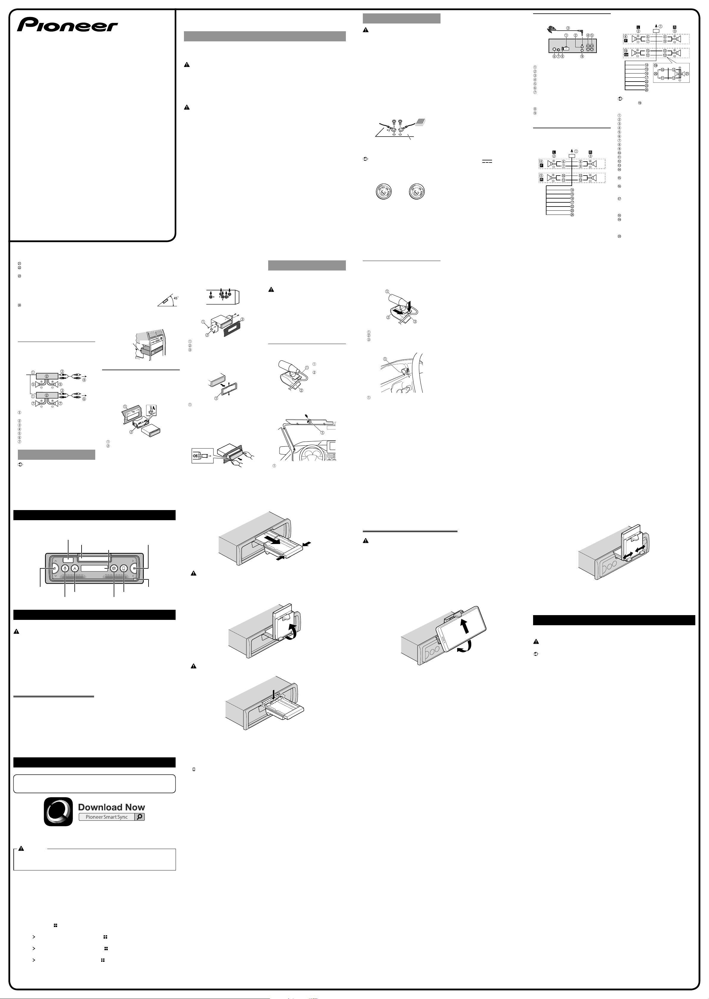
Pioneer Smart Sync is the application that intelligently brings
your maps, messages, and music together in the vehicle.
SMARTPHONE RECEIVER
SPH-C19BT
Quick start guide
CRB5151-B
This guide is intended to guide you through the basic functions of this unit.
For details, please refer to the Owner’s manual stored on the website.
http://www.pioneerelectronics.com/support
Before You Start
Thank you for purchasing this PIONEER product
To ensure proper use, please read through this guide before using this product. It is especially important
that you read and observe WARNINGS and CAUTIONS in this guide. Please keep the guide in a safe and
accessible place for future reference.
WARNING
• Do not attempt to install or service this product by yourself. Installation or servicing of this product
by persons without training and experience in electronic equipment and automotive accessories
may be dangerous and could expose you to the risk of electric shock, injury or other hazards.
• Do not attempt to operate the unit while driving. Make sure to pull off the road and park your vehicle in a
safe location before attempting to use the controls on the device.
• Slots and openings in the cabinet are provided for ventilation to ensure reliable operation of the product,
and to protect it from overheating. To prevent fire hazard, the openings should never be blocked or covered
with items (such as papers, floor mat, cloths).
CAUTION
• Do not allow this unit to come into contact with moisture and/or liquids. Electrical shock could result. Also,
damage to this unit, smoke, and overheating could result from contact with liquids.
• Always keep the volume low enough to hear outside sounds.
• This product is evaluated in moderate and tropical climate condition under the Audio, video and similar
electronic apparatus - Safety requirements, IEC 60065.
If you experience problems
Should this unit fail to work properly, please contact your dealer or nearest authorized PIONEER Service
Station.
Connections
WARNING
• When speaker output is used by 4 channels, use
speakers rated over 50 W (maximum input power)
and between 4 Ω to 8 Ω (impedance value). Do
not use 1 Ω to 3 Ω speakers for this unit.
• When rear speaker output is used by a 2 Ω
subwoofer, use speakers rated for over 70 W.
* Please refer to connections for a connection
method.
• The black cable is ground. When installing this
unit or power amp (sold separately), make sure
to connect the ground wire first. Ensure that
the ground wire is properly connected to metal
parts of the car’s body. The ground wire of the
power amp and the one of this unit or any other
device must be connected to the car separately
with different screws. If the screw for the ground
wire loosens or falls out, it could result in fire,
generation of smoke or malfunction.
Two devices connected to the car
separately (ground wires)
Metal parts of
*1 Not supplied for this unit
Important
• When installing this unit in a vehicle without an
ACC (accessory) position on the ignition switch,
failure to connect the red cable to the terminal
that detects operation of the ignition key may
result in battery drain.
ACC position No ACC position
• Use this unit with a 12-volt battery and negative
grounding only. Failure to do so may result in a fire
or malfunction.
• To prevent a short-circuit, overheating or
malfunction, be sure to follow the directions
below.
− Disconnect the negative terminal of the battery
before installation.
car’s body
− Secure the wiring with cable clamps or adhesive
tape. Wrap adhesive tape around wiring that
comes into contact with metal parts to protect
the wiring.
− Place all cables away from moving parts, such as
the shift lever and seat rails.
− Place all cables away from hot places, such as
near the heater outlet.
− Do not connect the yellow cable to the battery
by passing it through the hole to the engine
compartment.
− Cover any disconnected cable connectors with
insulating tape.
− Do not shorten any cables.
− Never cut the insulation of the power cable of
this unit in order to share the power with other
devices. The current capacity of the cable is
limited.
− Use a fuse of the rating prescribed.
− Never wire the negative speaker cable directly
to ground.
− Never band together negative cables of multiple
speakers.
• When this unit is on, control signals are sent
through the blue/white cable. Connect this cable
to the system remote control of an external power
amp or the vehicle’s auto-antenna relay control
terminal (max. 300mA 12 V DC). If the vehicle is
equipped with a glass antenna, connect it to the
antenna booster power supply terminal.
• Never connect the blue/white cable to the power
terminal of an external power amp. Also, never
connect it to the power terminal of the auto
antenna. Doing so may result in battery drain or
a malfunction.
• The graphical symbol
product means direct current.
placed on the
This unit
Power cord input
Microphone input
Microphone 3 m
Rear output or subwoofer output
Front output
Antenna input
Parking sensor input
UART adaptor (supplied with parking seonsor
unit (ND-PS1)) can be connected (sold
separately).
Fuse (10 A)
Wired remote input
Hard-wired remote control adapter can be
connected (sold separately).
Power cord
Perform these connections when not connecting a
rear speaker lead to a subwoofer.
Perform these connections when using a subwoofer
without the optional amplifier.
Important
In the case of
in parallel will represent a 2 Ω load.
To power cord input
Left
Right
Front speaker
Rear speaker
White
White/black
Gray
Gray/black
Green
Green/black
Violet
Violet/black
Black (chassis ground)
Connect to a clean, paint-free metal location.
Yellow
Connect to the constant 12 V supply terminal.
Red
Connect to terminal controlled by the ignition
switch (12 V DC).
Blue/white
Connect to the system control terminal of
the power amp or auto-antenna relay control
terminal (max. 300 mA 12 V DC).
Subwoofer (4 Ω)
When using a subwoofer of 2 Ω, be sure to
connect the subwoofer to the violet and violet/
black leads of this unit. Do not connect anything
to the green and green/black leads.
Not used.
above, two 4 Ω subwoofers wired
Subwoofer (4 Ω) × 2
Orange/white
Connect to a car’s illumination signal.
Violet/white
Of the two lead wires connected to the back
lamp, connect the one in which the voltage
changes when the gear shift is in the REVERSE
(R) position. This connection enables the unit
to sense whether the car is moving forwards or
backwards.
Light green
Used to detect the On/Off status of the parking
brake. This lead must be connected to the power
supply side of the parking brake switch.
NOTE
Change the initial menu of this unit. Refer to
[SP-P/O] in the INITIAL settings. The subwoofer
output of this unit is monaural.
Power amp (sold
separately)
Perform these connections when using the optional
amplifier.
System remote control
Connect to blue/white cable.
Power amp (sold separately)
Connect with RCA cables (sold separately)
To front output
Front speaker
To rear output or subwoofer output
Rear speaker or subwoofer
Installation
Important
• Check all connections and systems before final
installation.
• Do not use unauthorized parts as this may cause
malfunctions.
• Consult your dealer if installation requires drilling
of holes or other modifications to the vehicle.
• Do not install this unit where:
− it may interfere with operation of the vehicle.
− it may cause injury to a passenger as a result of
a sudden stop.
• Install this unit away from hot places such as near
the heater outlet.
• Optimum performance is
obtained when the unit is
installed at an angle of less
than 45°.
• When installing, to ensure proper heat dispersal
when using this unit, make sure you leave ample
space behind the rear panel and wrap any loose
cables so they are not blocking the vents.
Leave ample
space
5 cm
5 cm
DIN mount installation
1 Insert the supplied mounting sleeve into
the dashboard.
2 Secure the mounting sleeve by using a
screwdriver to bend the metal tabs (90°)
into place.
Dashboard
Mounting sleeve
• Make sure that the unit is installed securely
in place. An unstable installation may cause
skipping or other malfunctions.
When not using the supplied
mounting sleeve
1 Determine the appropriate position where
the holes on the bracket and the side of
the unit match.
2 Tighten the screws on each side.
Truss screw (5 mm × 9 mm)
Mounting bracket
Dashboard or console
Removing the unit (installed with the
supplied mounting sleeve)
1 Remove the trim ring.
Trim ring
• Releasing the front panel allows easier access
to the trim ring.
• When reattaching the trim ring, point the side
with the dent part up.
2 Insert the supplied extraction keys into
both sides of the unit until they click into
place.
3 Pull the unit out of the dashboard.
Installing the microphone
The microphone should be placed directly in front
of the driver at a suitable distance to pick up their
voice clearly.
CAUTION
It is extremely dangerous to allow the microphone
lead to become wound around the steering column
or shift lever. Be sure to install the microphone in
such a way that it will not obstruct driving. It is
recommended to use the clamps (sold separately)
to arrange the lead.
NOTE
Depending on the vehicle model, the microphone
cable length may be too short when you mount the
microphone on the sun visor. In such cases, install
the microphone on the steering column.
To install on the sun visor
1 Fit the microphone lead into the groove.
Microphone
lead
Groove
2 Install the microphone clip on the sun
visor.
Lowering the sun visor reduces the voice
recognition rate.
Microphone clip
To install on the steering
column
1 Slide the microphone base to detach it
from the microphone clip.
Microphone
Microphone clip
Microphone base
2 Install the microphone on the rear side of
the steering column.
Double-sided tape
Basic operation
SPH-C19BT
USB port
Smartphone holder
Display window
Message Voice recognition
Application launch
Detach button Source (music)/OFF
Phone Navigation
Operating the smartphone holder
WARNING
• Detach the smartphone from the holder while driving under bad road conditions since the smartphone
may fall from the holder.
• Do not leave the smartphone attached onto the holder.
• Do not use the holder if you experience difficulty when attaching the smartphone onto the holder.
• Do not operate the holder or smartphone while driving.
• Be careful not to get your hands and fingers caught in the moving parts while operating the holder.
• Do not attach the smartphone to the holder in a location where it may drop on the driver’s feet.
• Do not set the holder near the air conditioner vent.
• Make sure that nothing affects the operation of the air bags or vehicle operating systems, safety feature or
hazard lamps.
• PIONEER IS NOT RESPONSIBLE AND DISCLAIMS LIABILITY FOR ANY DAMAGES CAUSED THROUGH USE OF
THE PRODUCT OR VEHICLE.
Removing the smartphone holder
1 Detach the front panel.
2 Pull out the holder by holding the anti slip portion on the edge of the
holder until the holder is completely visible.
CAUTION
Never pull up the holder until the holder is completely visible.
3 Pull up the holder vertically.
CAUTION
Make sure that the line can be seen when the holder is pulled up vertically.
4 Attach the front panel to the unit.
Attaching the smartphone to the holder
CAUTION
• Depending on the shape of the smartphone, smartphone case or cover, it may not be attachable to the
holder.
• Be careful not to pinch your fingers in the holder.
Compatible smartphone size
H: 58 mm - 170 mm
W: 58 mm - 87 mm
D: 4 mm - 10 mm
Weight: under 0.25 kg
1 Hook the smartphone on the upper arm and then push it into the
lower arm.
2 Slide the lower arms position to avoid hitting the lower arm and
smartphone buttons against each other.
NOTES
• Make sure that the smartphone is held properly on the holder.
• When the smartphone buttons come in contact with the upper or lower arms, adjust the smartphone’s
position or turn the smartphone upside down.
Bluetooth connection
Up to two Bluetooth telephones can be connected simultaneously.
CAUTION
• Do not use mobile phone while driving.
Important
If ten or more Bluetooth devices (e.g. a phone and separate audio player) are connected, they
may not work properly.
1 Turn on the Bluetooth function of the device.
2 Select the unit name shown in the device display.
3 Make sure the same 6-digit number appears on this unit and the
device.
4 Select [Y].
Making a connection with Pioneer Smart Sync
For details on what operations are available on the application, see the application’s help
section.
WARNING WARNING
Do not attempt to operate the application while driving. Make sure
to pull off the road and park your vehicle in a safe location before
attempting to use the controls on the application.
1 Connect this unit with the mobile device via Bluetooth (refer to
“Bluetooth connection”).
Pioneer Smart Sync on the iPhone/Android device starts
automatically.
Pioneer Smart Sync connection via wired connection
You can also make the Pioneer Smart Sync connection via USB connection.
1 Press and hold to display the main menu.
NOTE
The automatic connection may fail depending on your mobile device. In that case, press and
.
hold
TIP
Once the Pioneer Smart Sync connection is made between the unit and the mobile device,
you can pair from the application on the mobile device from the next time.
2 Press to select [SYSTEM], then press to confirm.
3 Press to select [APP CTL], then press to confirm.
4 Press to select [WIRED], then press to confirm.
Pioneer Smart Sync on the iPhone/Android device starts
automatically.
Page 2

Compressed audio compatibility
• Only the first 32 characters can be displayed as a
file name (including the file extension) or a folder
name.
• The unit may not work properly depending on the
application used to encode WMA files.
• There may be a slight delay at the start of the
playback of audio files embedded with image
data, or audio files stored on a USB device with
numerous folder hierarchies.
CAUTION
• Pioneer cannot guarantee compatibility with
all USB mass storage devices, and assumes no
responsibility for any loss of data on media
players, smartphones, or other devices while using
this product.
• Do not leave a USB storage device in any place
that is subject to high temperatures.
WMA les
File extension .wma
Bit rate 48 kbps to 320 kbps
Sampling frequency 32 kHz, 44.1 kHz, 48 kHz
Windows Media™
Audio Professional,
Lossless, Voice/DRM
Stream/Stream with
video
(CBR), 48 kbps to 384
kbps (VBR)
Not compatible
MP3 les
File extension .mp3
Bit rate 8 kbps to 320 kbps
Sampling frequency 8 kHz to 48 kHz (32 kHz,
Compatible ID3 tag
version
M3u playlist Not compatible
(CBR), VBR
44.1 kHz, 48 kHz for
emphasis)
1.0, 1.1, 2.2, 2.3, 2.4 (ID3
tag Version 2.x is given
priority over Version
1.x.)
MP3i (MP3 interactive),
mp3 PRO
Not compatible
WAV les
File extension .wav
Quantization bits 8 and 16 (LPCM)
Sampling frequency 16 kHz to 48 kHz
(LPCM)
AAC les
Compatible format AAC encoded by
File extension .m4a
Sampling frequency 11.025 kHz to 48
Stereo Bit Rate 16 kbps to 320
Apple Lossless Not compatible
AAC file bought
from the iTunes
Store (.m4a file
extension)
iTunes
kHz
kbps, VBR
Not compatible
FLAC les
• FLAC files may not be playable, depending on
the encoder.
File extension .flac .fla
Sampling frequency 8/11.025/12/16/22
Quantization bit
rate
Channel mode 1/2 ch
.05/24/32/44.1/48/
96 kHz
8/16/24 bit
USB device
• There may be a slight delay when starting
playback of audio files on a USB storage device
with numerous folder hierarchies.
Playable folder
hierarchy
Playable folders Up to 1 500
Playable files Up to 15 000
Playback of
copyright-protected
files
Partitioned USB
device
Up to eight tiers (A
practical hierarchy is
less than two tiers.)
Not compatible
Only the first
partition can be
played.
Specications
General
Rated power source: 14.4 V DC (allowable voltage
range: 12.0 V to 14.4 V DC)
Grounding system: Negative type
Maximum current consumption: 10.0 A
Dimensions (W × H × D):
DIN
Chassis: 178 mm × 50 mm × 165 mm
Nose: 188 mm × 58 mm × 16 mm
D
Chassis: 178 mm × 50 mm × 165 mm
Nose: 170 mm × 46 mm × 16 mm
Weight: 1 kg
Audio
Maximum power output:
• 50 W × 4 ch/4 Ω (for no subwoofer)
• 50 W × 2 ch/4 Ω + 70 W × 1 ch/2 Ω (for
subwoofer)
Continuous power output:
22 W × 4 (50 Hz to 15 000 Hz, 5 % THD, 4 Ω
load, both channels driven)
Load impedance: 4 Ω (4 Ω to 8 Ω (2 Ω for 1 ch)
allowable)
Preout maximum output level: 2.0 V
Built in equalizer:
Frequency: 50 Hz/80 Hz/125 Hz/200 Hz/315
Hz/500 Hz/800 Hz/1.25 kHz/2 kHz/3.15 kHz/5
kHz/8 kHz/12.5 kHz
Gain: ±12 dB
High pass filter:
Frequency: 25 Hz/31.5 Hz/40 Hz/50 Hz/63
Hz/80 Hz/100 Hz/125 Hz/160 Hz/200 Hz/250
Hz
Slope: –6 dB/oct, –12 dB/oct, –18 dB/oct, –24
dB/oct, OFF
Subwoofer/Low pass filter:
Frequency: 25 Hz/31.5 Hz/40 Hz/50 Hz/63
Hz/80 Hz/100 Hz/125 Hz/160 Hz/200 Hz/250
Hz
Slope: –6 dB/oct, –12 dB/oct, –18 dB/oct, –24
dB/oct, –30 dB/oct, –36 dB/oct, OFF
Phase: Normal/Reverse
Speaker level:
+10 dB to –24 dB (1 dB step)
Time alignment:
0 cm to 350 cm (2.5 cm/Step)
USB
USB standard specification: USB 2.0 full speed
Maximum current supply: 1.5 A
USB Protocol:
MSC (Mass Storage Class)
AOA (Android Open Accessory) 2.0
File system: FAT12, FAT16, FAT32
MP3 decoding format: MPEG-1 & 2 Audio Layer 3
WMA decoding format: Ver. 7, 8, 9, 9.1, 9.2 (2 ch
audio)
AAC decoding format: MPEG-4 AAC (iTunes encoded
only) (Ver. 10.6 and earlier)
FLAC decoding format: v1.2.1 (Free Lossless Audio
Codec)
WAV signal format: Linear PCM (Non-compressed)
FM tuner
Frequency range: 87.5 MHz to 108.0 MHz
Usable sensitivity: 11 dBf (1.0 μV/75 Ω, mono, S/N:
30 dB)
Signal-to-noise ratio: 65 dB (IEC-A network)
AM tuner
Frequency range: 531 kHz to 1 602 kHz (9 kHz)
530 kHz to 1 640 kHz (10 kHz)
Usable sensitivity: 25 μV (S/N: 20 dB)
Signal-to-noise ratio: 60 dB (IEC-A network)
SW tuner
Frequency range:
2 300 kHz to 7 735 kHz (2 300 kHz to 2 495
kHz, 2 940 kHz to 4 215 kHz, 4 540 kHz to 5
175 kHz, 5 820 kHz to 6 455 kHz, 7 100 kHz to
7 735 kHz)
9 500 kHz to 21 975 kHz (9 500 kHz to 10 135
kHz, 11 580 kHz to 12 215 kHz, 13 570 kHz to
13 870 kHz, 15 100 kHz to 15 735 kHz, 17 500
kHz to 17 985 kHz, 18 015 kHz to 18 135 kHz,
21 340 kHz to 21 975 kHz)
Usable sensitivity: 28 μV (S/N: 20 dB)
Signal-to-noise ratio: 60 dB (IEC-A network)
Bluetooth
Version: Bluetooth 4.0 certified
Output power: +4 dBm Maximum (Power class 2)
BLE (Bluetooth Low Energy) Version: 4.0 certified
BLE (Bluetooth Low Energy) Output power: +3 dBm
Maximum
Frequency band(s): 2 400 MHz to 2 483.5 MHz
Bluetooth profiles:
GAP (Generic Access Profile)
SDAP (Service Discovery Application Profile)
HFP (Hands Free Profile) 1.6
PBAP (Phone Book Access Profile)
A2DP (Advanced Audio Distribution Profile)
AVRCP (Audio/Video Remote Control Profile)
1.5
SPP (Serial Port Profile) 1.1
NOTE
Specifications and the design are subject to
modifications without notice.
 Loading...