

Page 1

Flat Panel Speaker
S-FL1
ORDER NO.
RRV3263
S-FL1
XTW/E5
PIONEER CORPORATION 4-1, Meguro 1-chome, Meguro-ku, Tokyo 153-8654, Japan
PIONEER ELECTRONICS (USA) INC. P.O. Box 1760, Long Beach, CA 90801-1760, U.S.A.
PIONEER EUROPE NV Haven 1087, Keetberglaan 1, 9120 Melsele, Belgium
PIONEER ELECTRONICS ASIACENTRE PTE. LTD. 253 Alexandra Road, #04-01, Singapore 159936
PIONEER CORPORATION 2005
T-ZZS NOV. 2005 Printed in Japan
Page 2
1
N
1. PARTS LIST
OTES:
A
CS ASSY
Mark No. Description Part No.
NSP External Frame A SLH1087
NSP External Frame B SLH1088
NSP External Frame C SLH1089
NSP External Frame D SLH1090
NSP Frame Brace SNE1032
B
NSP Model Label SAN3543
Parts marked by "NSP" are generally unavailable because they are not in our Master Spare Parts List.
The mark found on some component parts indicates the importance of the safety factor of the part.
Therefore, when replacing, be sure to use parts of identical designation.
Speaker Assy SMW1901
Coner Protector A SNK2833
Coner Protector B SNK2834
Punching Net SNC1205
23
Mark No. Description Part No.
Screw (for Coner Protector) SKC50H350FTB
Screw (for Punching Net) SMZ40H060FTB
Screw (for Cap) SMZ60H200FTB
Input Terminal Ass’y SKX1099
NSP Cord D SDB1157
NSP Cord E SDB1158
Insulating Tube SDM1007
NSP Insulating Tube SDM1008
NSP Input Terninal SKN1010
4
NSP Serial Label SAX1420
C
NSP Wiring Label SRW1113
Packing
D
Insulating Tube SDM1007
Packing A SEC2007
Packing B SEC2008
Packing SEC2067
Suspension C SEP1347
Input Terminal Base SNK2835
Cap SNK2836
Handle SNK2837
Screw (for Frame Brace) BMZ40P080FTC
Screw (for Input Terninal) OPZ30P100FTB
Screw (for Input Terminal Base) PMZ30P250FTC
Screw (for Handle) PMZ40P100FTB
Screw (for External Frame) PMZ40P350FTC
1
4
For Packing
Mark No. Description Part No.
1 Protector SHA2511
2 PS Spacer SHA2527
3 Protector SHB1171
4 Protection Sheet SHC1833
5 Packing Case SHG2705
NSP 6 Accessories Set SME3691
7 Polyethylene Bag S2 SHL1420
8 Operating Instructions SRD1290
(English, French, German,
Italian, Spanish, Dutch, Chinese)
Protector Set
1
5
E
6
8
Sticks
Protector Set
Protector Set
7
The line that
shows a position
F
2
Fixes using tapes.
3
2
1234
S-FL1
Page 3
1
234
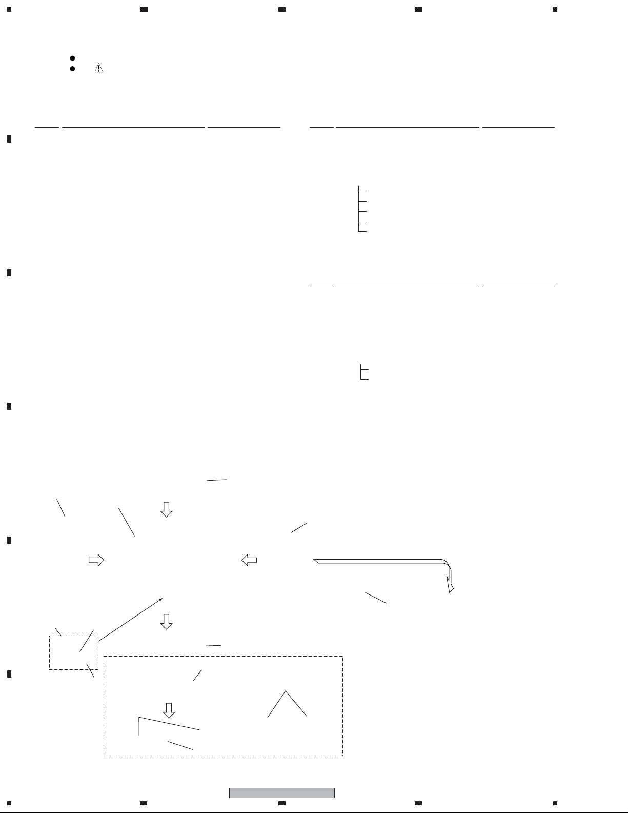
2. FOR PRECAUTION OF DISASSEMBLY AND REASSEMBLY
2-1. DISASSEMBLY
Detach the Coner Protector A,B
and Cap
Screw
(SKC50H350FTB)
x 2pcs.
Screw
(SKC50H350FTB)
x 2pcs.
Wiring Label
Screw(SMZ60H200FTB) x 4pcs.
Cap x 4pcs.
(SNK2836)
< Back Side >
Wiring Label
Model Label
Packing (SEC2067)
x8pcs.
Serial
Label
A
Handle(SNK2837)
Screw(PMZ40P100FTB) x 2pcs.
Screw
(SKC50H350FTB)
x 2pcs.
B
Speaker System
Frame Brace (NSP)
Coner Protector A : 4pcs.
(SNK2833)
Coner Protector B : 4pcs.
(SNK2834)
C
Screw
(SKC50H350FTB)
x 2pcs.
Detach the Punching Net
Packing B (Long)x 2pcs.
(SEC2008)
Packing B (Long)x 2pcs.
(SEC2008)
< Front Side >
Screw
(SMZ40H060FTB)
x 20pcs.
Punching Net
(SNC1205)
Packing A (Short)x 2pcs.
(SEC2007)
Packing A (Short)x 2pcs.
(SEC2007)
Punching Net
(SNC1205)
Screw
(SMZ40H060FTB)
x 20pcs.
D
E
F
S-FL1
1
2
3
4
3
Page 4

1
23
4
Disconnect the Input Terminal Assy Cords and Speaker Assy Cords
A
Insulating Tube (SDM1007)
A
B
B
C
Insulating Tube
(SDM1007)
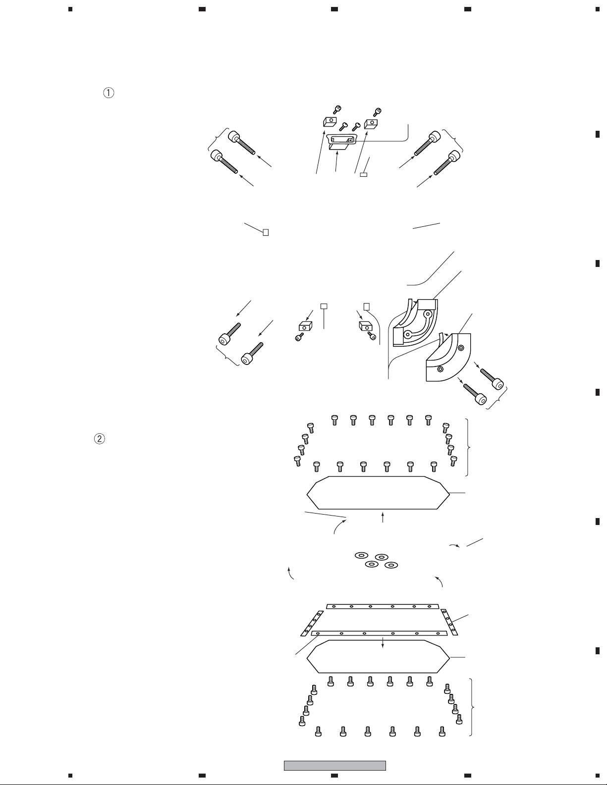
Unfasten the Screw for the External Frame and Detach the Frame Brace
Screw for External Frame
(PMZ40P350FTC) x 12pcs.
Screw for Frame Brace (BMZ40P080FTC)
D
E
Tu r ns over the speaker.
Screw for Frame Brace
(BMZ40P080FTC)
Screw for
External Frame
(PMZ40P350FTC)
Screw for Frame Brace
(BMZ40P080FTC)
Cord
< Back side >
Screw for Frame Brace (BMZ40P080FTC) x 16pcs.
Screw for Frame Brace
(BMZ40P080FTC)
Screw for
External Frame
(PMZ40P350FTC)
Screw for Frame Brace
(BMZ40P080FTC)
Frame Brace (NSP) x 4pcs.
Be careful of direction.
Screw for Frame Brace
(BMZ40P080FTC)
Screw for
F
4
1234
External Frame
(PMZ40P350FTC)
S-FL1
Cord
Screw for Frame Brace
(BMZ40P080FTC)
Page 5

1
234
Detach the External Frame
Speaker Assy
(SMW1901)
Screw for External Frame
(PMZ40P350FTC)
External Frame A
(NSP)
The direction that the
speaker cord comes.
Screw for External Frame
(PMZ40P350FTC) x 6pcs.
< Front Side >
Hole
Screw for External Frame
(PMZ40P350FTC)
Hole
External Frame B
(NSP)
The direction that the
speaker cord comes.
Draw out the cord from
the hole of External Frame D.
External Frame D (NSP)
Draw out the cord from
the hole of External Frame B.
External Frame C
(NSP)
Screw for
External Frame
(PMZ40P350FTC)
A
B
C
2-2. REASSEMBLY
Reassembles by the order of -> -> Connecting the Input Terminal Assy cord and
the Speaker Assy cord, Puts the Insulation Tube, Styling the connection cord -> -> .
Note 1) When you attach the Extenal Frame A, B, C, D to the speaker at first,
don't tighten the screw strongly.
But when you attach the Frame brace, fasten the screws strongly.
Note 2) Stick the Suspension C
Stucks the suspension C on the center of the
frame back side, as shown in a figure.
Suspension C (SEP1347)
Note 3) Attach the Corner Protector
Sticks the Packing to the Corner Protector.
Covers the Frame Brace by the corner protector
and fasten the Screws.
< Front side >
Frame Brace
Corner Protector A x4pcs.
Corner Protector B x4pcs.
D
E
(SNK2833)
(SNK2834)
Note 4) Attach the Punching Net
The Punching Net have distinction of the front and
the back side. The side which has burr arround the
hole is the back side. Be sure to attach it to inside.
1
2
Packing (SEC2067) x8pcs.
(Sticks on the illustration part
of the corner protector inner side.)
S-FL1
3
2pcs. in each
every corner
(SKC50H350FTB)
4
F
5
Page 6

1
23
4
2-3. CONNECTING and SCHEMATIC DIAGRAM
Input Terminal Ass'y (SKX1099)
A
Input Terminal Ass'y (SKX1099)
Puts through the tube firmly.
The Insulating Tube is not shrunk. (Do not heat.)
Move the Insulating Tubes to the soldering part
and fixes by heating.
B
C
Input Terminal (SKN1010)
Cord E
Puts through the tip of code into a terminal hole.
After bending, solders.
Insulating Tube
Cord D
The terminal number to connect
Connects the code (Black) to [1-] terminal.
Connects the code (White) to [1+] terminal.
Attach the Input Terminal Ass'y
Previously, puts through the cord to the Input Terminal Base.
Then puts through the cord to External Frame.
The direction that takes out
Direction of the metal plate
the Input Terminal Assy Cords.
A
D
Screw
OPZ30P100FTB
(2 pcs.)
Input Terminal Assy
Screw
E
F
Input Terminal Base
(SNK2835)
(Puts through previously)
Direction of the metal plate
6
1234
PMZ30P250FTC
(2 pcs.)
Input Terminal Base (SNK2835)
(Puts through previously)
S-FL1
< Back Side >
B
The direction that takes out
the Input Terminal Assy Cords.
Screw
PMZ30P250FTC (2 pcs.)
Input Terminal Assy
Screw
OPZ30P100FTB
(2 pcs.)
Page 7

1
234
Connection of the Input Terminal Ass'y Cords and the Speaker Assy Cords
Insulating Tube (SDM1007)
A
Solders, after twisting the Cord 3 times
or more.
Connect the same color cord.
B
Insulating Tube
(SDM1007)
A
B
C
Styling
Tu r ned up the connection part and the cord and puts into the inside of External Frame.
In this position, Pushes the connection part in
A
Pushes the cord in between
the Frame and the Frame Brace.
Puts the cord into the inside of
External Frame.
Checks that the cord has not
appeared from Extenal Frame.
Extenal Frame C
between the Frame and the Frame Brace.
B
Extenal Frame D
Tu r ned up the connection part
and puts into the inside of
External Frame.
Checks that the cord has not
appeared from Extenal Frame.
Tu r ned up the cord.
D
E
F
S-FL1
1
2
3
4
7
Page 8

1
23
4
Connecting to your amplifier
A
Disconnecting
Squeeze the lever on the speaker connector with your
thumb, then twist the whole connector counter-
Caution
• Be careful not to short the two pins (1+ and 1–) of the
free speaker terminal. Doing so could damage the
clockwise and pull out.
2
speaker and your amplifier.
• Switch off the amplifier before connecting any
speakers.
1
There are two connection terminals on the rear side of
the speaker. To connect the speaker to your amplifier you
will need a suitable speaker cord terminated in a Neutrik
B
Speakon
®
speaker connector [NL4MP]. Only the 1+ and
1– pins should be connected. These connect to the
positive (+) and negative (–) speaker terminals
respectively on the amplifier.
Neutrik [NL4FX] and [NL4FC] Speakon speaker cord can
Connecting another speaker
On the rear of the speaker are two terminals; you can use
these to connect another speaker of the same type to this
speaker.
S-FL1 S-FL1
be used for the connection. Please refer to Neutrik for
more information.
Amplifier
1 Use a suitable speaker cord (not supplied) to
connect the speaker terminal on your amplifier to
one of the input terminals on the rear of the
speaker.
C
whichever is convenient.
• See the manual that came with your amplifier for
more details.
The speaker’s terminals are exactly the same; use
• The number of speakers you may connect will vary
according to the impedance rating of the amplifier.
See the manual that came with your amplifier for
more details.
• The diagram below shows the wiring of two
connected speakers.
a Plug the speaker cord connector into the
speaker's input terminal. Check the alignment for
S-FL1 S-FL1
the connector with the jack before plugging in.
Amplifier
+
1+
1+
11+1+
8 Ω
1-
EXCITER
EXCITER EXCITER
EXCITER
Input
1-
8 Ω
1-
White
Black
-
D
b After inserting the connector fully, turn
SCHEMATIC DIAGRAM
clockwise to lock it in place.
1+ 1+
E
• After connecting, gently pull the connector to make
1– 1–
2+ 2+
2– 2–
Input
Terminal 1
Terminal 2
sure that it is securely connected. Improper
connection can be a cause of noise or other
problems.
F
8
S-FL1
1234
Page 9

3. JIGS
1
234
SPEAKON (GGF1541)
1. Turn the black cap leftward and removed.
(Don't turn rightward)
Part APart A Part BPart B Part CPart C
2. Loosen the screw and insert the speaker
cable in the silver color hole of [1-] and [1+].
Next tighten the screws. (Part A)
1+
1-
2+
2-
SPEAKER STAND for S-FL1
Please make this stand by your side.
250
150
75
2–φ9 HOLES
250
Screw M8, Screw Length 35
Measure for abnormal sound, be sure to use
the washer(M8) and the spring washer(M8).
[ mm ]
A
20 19
6565
B
C
• Usually, [1+] is connected as [+] and [1-] is
connected as [-].
• In case of the diameter of speaker cable is thin,
please stick a tape etc. and make the diameter
of cable thick.
3. After connecting the speaker cable, according
to the thickness of a cable, it inserts in order of
the adapter(for fixation) and the cap, and it turns
rightward and fixes.
• There is a lock mechanism.
Disassembly will be impossible once
it assembles.
4. Finish
D
E
F
S-FL1
1
2
3
4
9
Page 10

1
Jigs List
23
4
A
SPEAKON GGF1541
B
C
Jig Name Jig No. Note
The check of operation
D
E
F
10
1234
S-FL1
 Loading...