

Pioneer SFCRW-2700 Service manual
ORDER NO.
Sub Woofer
Center
Front
Surround
RRV3361
SPEAKER SYSTEM
S-FCRW2700 XTW/UC
This service manual is intended for qualified service technicians; it is not meant for the casual do-ityourselfer. Qualified technicians have the necessary test equipment and tools, and have been trained to
properly and safely repair complex products such as those covered by this manual.
Improperly performed repairs can adversely affect the safety and reliability of the product and may void the
warranty. If you are not qualified to perform the repair of this product properly and safely, you should not risk
trying to do so and refer the repair to a qualified service technician.
WARNING
This product contains lead in solder and certain electrical parts contain chemicals which are known to the state of California to
cause cancer, birth defects or other reproductive harm.
Health & Safety Code Section 25249.6 – Proposition 65
1. FOR PRECAUTION OF REASSEMBLY AND DISASSEMBLY
Front Speaker, Surround Speaker
The grille assy is attached to the cabinet by 4 screws.
To detach it, unfasten those screws.
The speaker unit, together with the Grille, is attached to the
cabinet by 4 external screws.
To detach it, first unfasten those screws. Next remove the cabinet. Then remove the cable.
When attaching it, face its terminal downward.
PIONEER CORPORATION 4-1, Meguro 1-chome, Meguro-ku, Tokyo 153-8654, Japan
PIONEER ELECTRONICS (USA) INC. P.O. Box 1760, Long Beach, CA 90801-1760, U.S.A.
PIONEER EUROPE NV Haven 1087, Keetberglaan 1, 9120 Melsele, Belgium
PIONEER ELECTRONICS ASIACENTRE PTE. LTD. 253 Alexandra Road, #04-01, Singapore 159936
PIONEER CORPORATION 2006
Center Speaker
The grille assy is attached to the cabinet by 8 external screws.
To detach it, unfasten those screws.
The speaker unit, together with the grille assy, is attached to the
cabinet by 4 external screws.
To detach it, unfasten those screws. To detach it, first remove
the cabinet. Then remove the cable.
When attaching it, face its terminal toward the input terminal.
Subwoofer
The subwoofer is attached to the rear baffle by 4 external
screws. To detach it, unfasten those screws.
When attaching it, face its terminal rightward.
T – ZZS FEB. 2006 Printed in Japan
1
N
2. PARTS LIST
23
4
A
OTES:
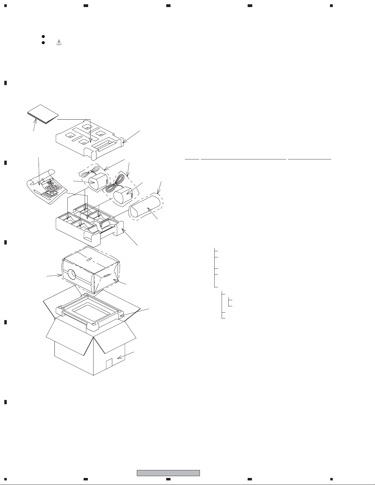
2.1 Packing
B
C
Parts marked by "NSP" are generally unavailable because they are not in our Master Spare Parts List.
The mark found on some component parts indicates the importance of the safety factor of the part.
Therefore, when replacing, be sure to use parts of identical designation.
7
6
5
12
13
2
1
3
Packing Parts List
Mark No. Description Part No.
NSP 1 Front Speaker SMW1938
NSP 2 Surround Speaker SMW1939
NSP 3 Center Speaker SMW1940
NSP 4 Subwoofer SMW1941
NSP Model Label (FL) SAN3849
NSP Model Label (FR) SAN3850
NSP Model Label (SL) SAN3851
NSP Model Label (SR) SAN3852
NSP Model Label (C) SAN3853
NSP Model Label (SW) SAN3854
8
10
D
4
9
11
E
NSP 5 Accessary Set SEA1719
Speaker Cord (for center) SDS1173
Non Skid Pad SEP1240
(for Front, Surround, Center)
Non Skid Pad (for Subwoofer) SEC1912
Polyethylene Bag S1 SHL1296
NSP Bracket Set SEA1720
NSP Screw Set SEA1721
Screw BMZ50P120FNC
Polyethylene Bag S0 SHL1314
Bracket SNN1047
Polyethylene Bag S1 SHL1429
6 Operating Guide SRD1317
(English, French)
7 Top Protector SHA2489
8 Middle Protector SHA2490
9 Bottom Protector SHA2491
10 Protection Sheet SHC1821
11 Packing Case SHG2739
12 Polyethylene Bag S2 SHL1417
13 Polyethylene Bag S1 SHL1419
F
2
1234
S-FCRW2700
1
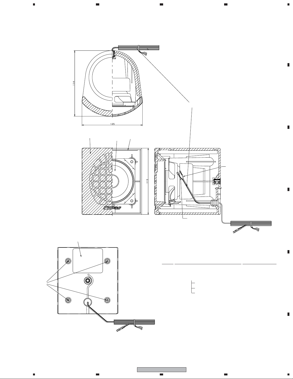
2.2 Front Speaker
234
A
B
23 or 24
Model Label
22
25
21
White
White with
Gray Line
Front Speaker Parts List
Mark No. Description Part No.
NSP 21 Cabinet SNK2840
C
D
26
< BACK VIEW >
1
22 Grille SMG1875
NSP Badge 28 SAM1506
NSP Grille Cloth SAS1614
NSP Baffle SNK2843
23 Connecting Cord (White) SDD1340
24 Connecting Cord (Red) SDD1341
25 Speaker K77DC55-52F
26 Screw BPZ35P120FTB
S-FCRW2700
2
3
4
E
F
3
 Loading...