

Pioneer SEV-1000-V Service manual
Front
Sub Woofer
Surround
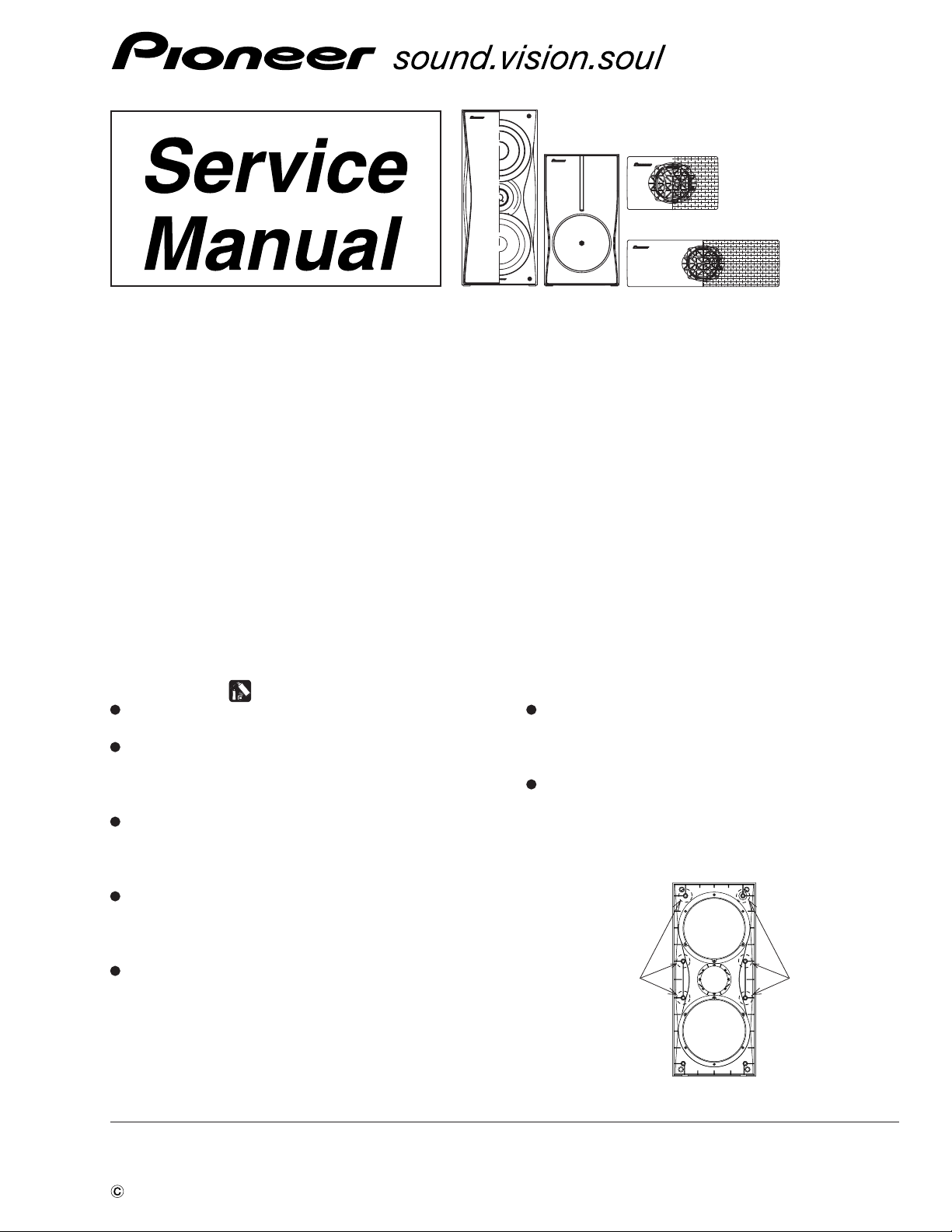
SPEAKER SYSTEM
S-EV1000V
S-EV1000V XJM/NC
Center
ORDER NO.
RRV3179
XJM/E
FOR PRECAUTION OF
REASSEMBLY AND DISASSEMBLY
CS Assy ( Front )
The grille assy is attached to the cabinet by catches. Detach by
pulling it toward you.
The catch is attached to the cosmetic baffle by press-fitting. To
detach it, insert a sharp-pointed tool like an eyeleteer into each
of side. To attach it, insert the holes of the cosmetic baffle assy
by press-fitting.
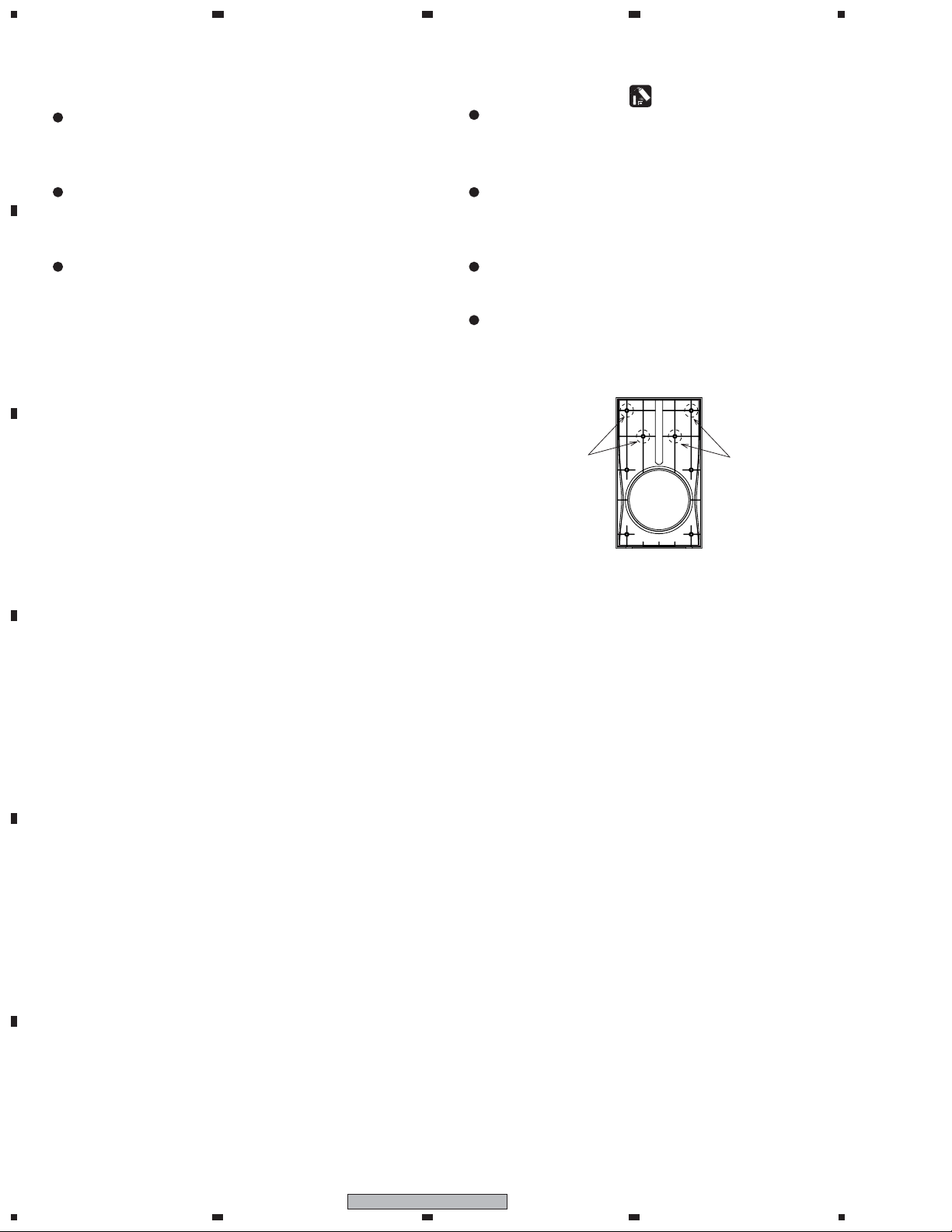
The cosmetic baffle assy is attached to the inner baffle by its
bosses. To detach it, pry it open by inserting a flat blade screw
driver into lower slot. To attach it, clean the press-fitting part
and apply a bit of adhesive . Then press it to the bafle. (Fig. 1)
The tweeter is attached to the cosmetic baffle by 2 internal
screws. To detach it, first remove the cosmetic baffle and the
connecting cord to a tweeter. Then unfasten those screws.
When attaching it, face its terminal downward.
The woofer is attached to the inner baffle by 4 screws with the
screw heads facing the cosmetic baffle. To detach it, first remove the cosmetic baffle and the connecting cord to a tweeter.
Then unfasten those screws. To attach it, replace the connecting
cord to a tweeter correctly and face its terminal downward. If
the connecting cord with packing overflows a slot, it will become the cause of air-leak and unusual sound.
The passive radiator is attached to the inner baffle by 4 screws
with the screw heads facing the cosmetic baffle. To detach it,
first remove the cosmetic baffle and the connecting cord to a
tweeter. Then unfasten those screws.
The input terminal is attached to the back board by press-fitting
and glue. To detach it, pry it open by inserting a flat blade
screwdriver into the lower side. When attaching it, the red terminal is right-side.
apply adhesive apply adhesive
Fig. 1
PIONEER CORPORATION 4-1, Meguro 1-chome, Meguro-ku, Tokyo 153-8654, Japan
PIONEER ELECTRONICS (USA) INC. P.O. Box 1760, Long Beach, CA 90801-1760, U.S.A.
PIONEER EUROPE NV Haven 1087, Keetberglaan 1, 9120 Melsele, Belgium
PIONEER ELECTRONICS ASIACENTRE PTE. LTD. 253 Alexandra Road, #04-01, Singapore 159936
PIONEER CORPORATION 2005
T – ZZK JUNE 2005 Printed in Japan
1
23
4
CS Assy ( Surround and Center )
A
The grille assy is attached to the cabinet by 4 external screws.
To detach it, unfasten those screws. When attaching it, it attaches, as the connection cord is under the speaker unit.
( Surround )
The grille assy is attached to the cabinet by 8 external screws.
To detach it, unfasten those screws. When attaching it, it attaches, as the connection cord is under the speaker unit.
( Center )
The speaker unit is attached to the grille by 4 internal screws.
To detach it, first remove the grille assy. Next unfasten those
B
C
screws, and remove the cable. When attaching it, face its terminal leftward. (See to the backside of the grille assy.)
CS Assy ( Subwoofer )
The cosmetic baffle is attached to the cabinet by its bosses. To
detach it, pry it open by inserting a flat blade screw driver into
lower slot. To attach it, clean the press-fitting part and apply a
bit of adhesive . Then press it to the bafle. (Fig. 2)
The passive radiator is attached to the baffle by 4 external
screws. To detach it, first remove the cosmetic baffle. Then remove the passive radiator. When attaching it, face its the rib for
input terminal board toward the vertical direction.
The woofer is attached to the back board of cabinet by 4 external screws. To detach it, unfasten those screws. When attaching
it, face its terminal upward.
The input terminal is attached to the back board by press-fitting
and glue. To detach it, pry it open by inserting a flat blade
screwdriver into the lower side. When attaching it, the red terminal is right-side.
apply adhesive
apply adhesive
Fig. 2
D
E
F
2
1234
S-EV1000V
1
N
PARTS LIST
OTES:
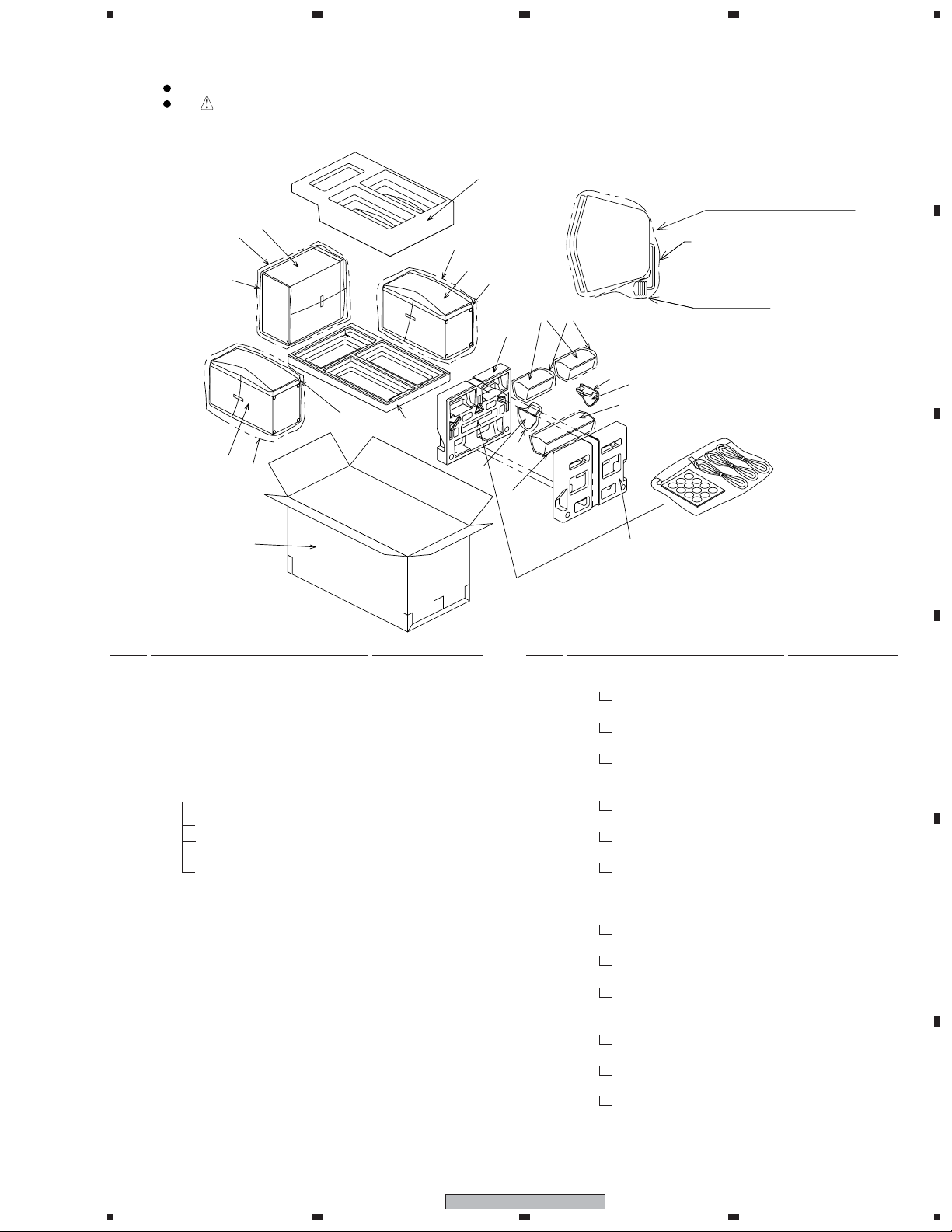
For Packing
Parts marked by "NSP" are generally unavailable because they are not in our Master Spare Parts List.
The mark found on some component parts indicates the importance of the safety factor of the part.
Therefore, when replacing, be sure to use parts of identical designation.
234
A
How to pack(surround & center)
11
8
2
15
10
1
15
16
9
15
1
10
4
7
12
5
14
13
12
5
3
6
7
*Pay attention
Should not touch the cabinet
and connecting cord directly.
poly bag
fastening
(clear tape)
B
C
Mark No. Description Part No.
NSP 1 CS Assy (Front) SMW1891
NSP 2 CS Assy (Sub Woofer) SMW1892
NSP 3 CS Assy (Center) SMW1888
NSP 4 CS Assy (Surround L) SMW1889
NSP 4 CS Assy (Surround R) SMW1890
5 Stand SNK2874
NSP 6 Accessories Set SEA1701
Speaker cord SDS1185
Speaker cord SDS1186
Speaker cord SDS1187
Non Skid Pad SEC1938
NSP Poly Bag S1 SHL1431
7 Satellite Protector SHA2497
8 Top Protector SHA2500
9 Bottom Protector SHA2501
10 Protection Sheet S3 SHC1828
11 Protection Sheet S4 SHC1827
NSP 12 Poly Bag S1 SHL1431
13 Poly Bag S3 SHL1432
NSP 14 Poly Bag S4 SHL1433
NSP 15 Poly Bag S7 SHL1435
for XJM/E type
16 Packing Case SHG2655
for XJM/NC type
16 Packing Case SHG2656
Mark No. Description Part No.
for XJM/E type
NSP Stanped Label (Front L) SME3647
NSP Model Label (Front L) SAN3685
NSP Stanped Label (Front R) SME3648
NSP Model Label (Front R) SAN3686
NSP Stanped Label (Sub WF) SME3649
NSP Model Label (Sub WF) SAN3687
NSP Stanped Label (Center) SME3650
NSP Model Label (Center) SAN3688
NSP Stanped Label (SUR.L) SME3651
NSP Model Label (SUR.L) SAN3689
NSP Stanped Label (SUR.R) SME3652
NSP Model Label (SUR.R) SAN3690
for XJM/NC type
NSP Stanped Label (Front L) SME3653
NSP Model Label (Front L) SAN3691
NSP Stanped Label (Front R) SME3654
NSP Model Label (Front R) SAN3692
NSP Stanped Label (Sub WF) SME3655
NSP Model Label (Sub WF) SAN3693
NSP Stanped Label (Center) SME3656
NSP Model Label (Center) SAN3694
NSP Stanped Label (SUR.L) SME3657
NSP Model Label (SUR.L) SAN3695
NSP Stanped Label (SUR.R) SME3658
NSP Model Label (SUR.R) SAN3696
D
E
F
1
2
S-EV1000V
3
4
3
 Loading...