

Page 1
()rrloNEErr"
STEREO
The
HG
type employs
service
AMPLIFIER
performance
basic
manual
with the exception
metal. This
SPECIFICATIONS
The
specifications for HG
type except for
following
sections;
Semiconductors
Transistors
Preamplifier
TAPE
2
(DlN
connector)
Section
REC(Level/lmpedance)
(Sensitivity/lmpedance)
PLAY
Hum
and Noise
(DlN,
Continuous
PHONO1MM.
PHONO2MM.
TUNER,
AUX, TAPE
pLAy
9BOOHG
of the HG
type is
additional
service
of this supplements.
type is the same as
.... 30mV/80kilohms
.
150mV/50
. .
Power/50mW)
....72d8162d8
....72dB162d8
1
. .
,2
the
same as
manual
the KU
....15
kilohms
g0dBl62dB
the KU
is applicable
type.
Power
Continuous Power
Micellaneous
Power
PowerConsumption
Dimensions
Weight
The KU
to the HG
Amplifier
T.H.D.
0.002%,8 ohms
Requirements
(Without
type has
please
type,
Section
Output at I kHz
1
6-1
Package)
a wooden
refer
cover, while
to the
KU type
(both
. . 100 watts
220V
channel
per
1240V
..... 850W(max.)
a20(W)x150(H)x425(D)mm
.
7
32(w
I
-2s
|
32
(H)
)
x s
. . . 18.0kg
x1
63 I a(D\in
(39
driven)
channel
50l60Hz
,
tb 11oz)
CONTRAST
P.C.
BOARD ASSEMBLIES
Symbol
PIONEEFI
U.B. FIONEEFI
PIONEEFI
PfONEEFT
<ART-341-0>
OF
PA-L
assembly
PA-R
assembly
Power
supply assembly
EO
assembly
Input terminal
Tape
terminal
DIN
connector
Tape
switch
ELECTFICINIC
ELECTFICINICA
ELECTFIONIC
ELECTFICINIC€i
MISCELLANEOUS
Description
assembly
assembly
assembly
assembly
CCIFIPCIFIATICTN
QCIFTPOFIATION A5 Oxto.d Dl ve. Moonach,e,
(EIJFIOPE
AU€lTFlALlA
N.\,. L'rchagen-Hawen
PYY.
LTEI.
PARTS
178 184
KU
type HG type
GWH-119
GWH-120
AWR.191
GWF.1
16
GWX.261
GWX-262
GWS-172
4 1 Mesuno 1-chon,e,
2O3O A,rcwe.p.
9,
EloL,ndany Road. Elnaes,de.
New Jensey
E}etg,um
Part
No.
GWH-125
GWH-126
AWR-196
GWF-1 18
GWX-291
GWX.292
GWX-293
GWS-183
MesL,.o-ku, rokyo 1ss,
A7O74. U.S A
V,.ilon,a
3195, Arrstnat,a
Japan
y
o
FEB.
Remarks
-1979
printed
in
lapan
Page 2
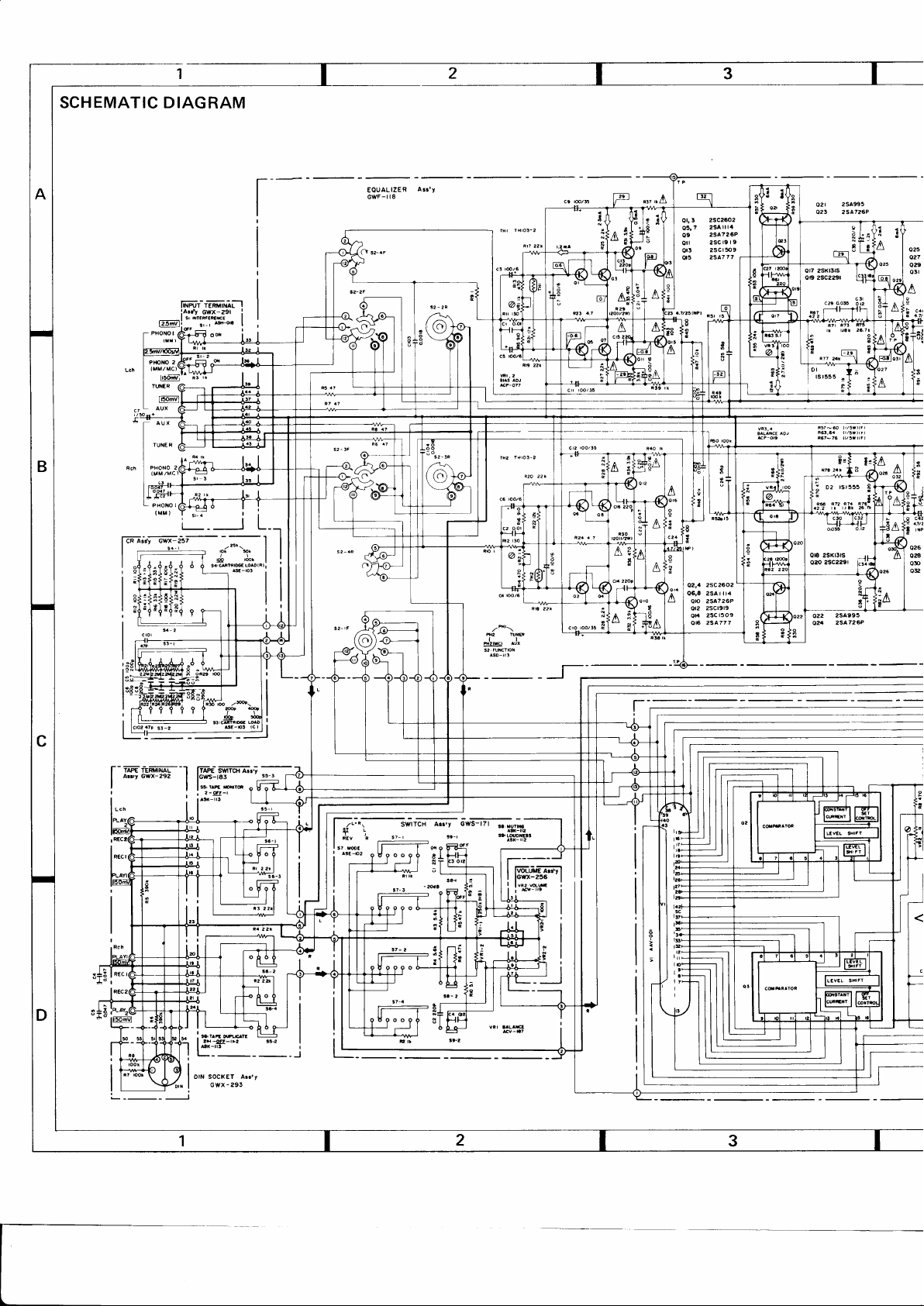
SCHEMATIC DIAGRAM
IINPUT
iarrt
sr fttE#EmrcE
I
f2Jdl;
__
"*ol*o,',ffi5
2
PltOxO
i
(MMlMC).
r6ffi
rr.ilER
(
llFmvl
AUX
I
TERIIII{AL
Cwx-zgr
e-oc
e1-1
oo"
EOUALIZER
GWF-t
A!r'Y
I I
I
o25
ozf
o29
o5l
rl\
I
i
I
I
j
R57-60
lrl5v)tFl
(l/5W'rFJ
R6.64
R67-76
il/5ftrF)
2SC26O2
Qz,a
06,8 2SA | il4
2sa726P
0lo
2sct919
or?
2SCl509
0r
016 2SA777
9
E :i)
:
i
026
o2a
OT
Ole
a|/a
trP
l--ffir=effiiMl--1
arey Gwx-2s2
I
:l
SWTC}I A...y
ITAPE
fGwS-t83
|
r^E
$,
drra
|
"'"'.TI:,,i""
?-
|
s5-r
o H o A__l_
-
[-r*"fw]rffi
Itr I
n:v P
I
I fI
sr
mc
| [----f-
s7-
!a-l
|
q
o F
f-w--n
Page 3
2SA995
|
3 2SA726P
-;-
l--
| 6FF ^orsr
l-L-
F|LTEF
$SSONiC
sr!
I
^*-"2
|
I
I
/2 Ar.'y
SWITCH
J":
__l
I
I
'
t,
l*#K'-, ^
AcP
(4
or5
I
I
l
5
E
:
^CP- OO7
o aorr""-o
!
02,
xat2oto
oF4
2-rK26
t;'
Y
i-
2scter4a
07
09 2SC945A
2sD712
oru3
I
i
[#
4f
I
I fFl,,.^
^Or
A]
J.!t3
r
|
(9s
. Dn n2't77 | -
Page 4

SA.9Elclcl,HGi
!$os
d
r07 2sa9r2
09
qr
Q13
0r5,r7
;+ors
3
0r,
05
07
09
05.
zsrszs
23A7265
2scr885
25Cr400
2SA750
2scr4oo
2SC229l
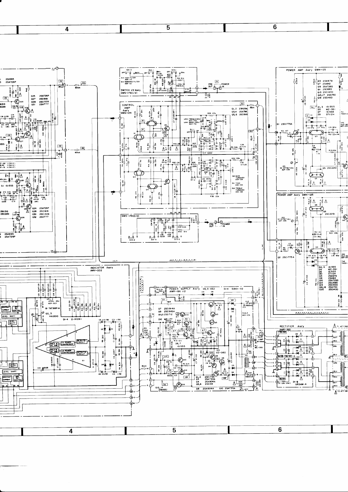
NOTE:
The
indicated
semiconductors are
representatiue
ones
only. Other alternatiue semiconductors may be used and
parts
lolaranc€ unl6soth.rwrg
(G).
rl%.
12%.
unl.s oth.rwe
erc.pt 11610lytrc
5OV
+lOOt/
lOOfl
.t
no input
at
sqn.l
volt# at raid
ngnal
componcnl
Fm.
gfcty
l*ror
to
h $r.
u!
list.
lKl.
8O
pomr
p.rl3
rh.
of
p..tr
ouput
!1096
Ind,
parr
ol
-.l
Lch
(A)
SPEAX€R
I
pq6
--l
SP_B
Lcn-_l
(8)
SPEAXER
I
RchJ
are listed in the
I R€SISTOR,
Indrcatd rn Q, l/4W,
rst555
Dil,t3,t3,17
ot9,?t,23,25 tsz4fl
ts247l
o27,8
2SA904A
o2t
o25 2SA733A
2SC945A
o27
2SCt9r3
o33
o23 025
027
029
2scraeoA
o23
25A733A
O29
;
2sce45A
o3r
2SCr890A
A
o24
2sA733A
o30
;
2sca45A
o32
036 2SA9r3
-
F
f
l
r
rE"e-l
FnR
_rl,
A
A
,-l
nord k, kO, M. MO.
2 CAPACITORS,
Indrc.td ro
IndcarDn *rrh@r voltry rs
VOLTAGE,
3
f!
El
€mA
4
OTHERS,
r>
Oo.Adru:tngPo'nt
Th.
c.tes tha
Th.r.lor!. S.n
rdcnrral
Srgnat
OC voh4
.
V.lue
OC current ar
.
SEn.t
.
m.tk lound
A
dGn9naton
c.p-riy
CUBRENT,
rmFri.nca
volt#
rn
rtut€
(
rcpl-'ng,
!5%
(F).
{!F)/volt+(V)
(Vl
tr OC
I
no Inpur
on
ol lha
)l
2ao
5I7 LINE VOLIAGE SEI€CIOR
zry-2.oy
A
^xx-o57
5r7
ot2, t4, t6,
D2O,22,21
026,26,
ac220l
9AON'
I
[e'!iY/qd
AT
SP IW
2sc945A
or,2
FILTEn
FILTER
vary due
Q3 zscrg€5
rS247l
Dr,2,3
04 MZ-r50
MZ - OAI
D5
diagram, but the
improvements in
to
9IIm-8kHz
!!JSE!-DrH
qEE-
22
gEE-ON
suitch
5nz
I
A- B-
0V-:40v
position.
A+B
actual
disign.
l-l
t8
ts247l
30
rs247l
SXITCHES:
Sl:
s2:
sl: cARTRrocE LoaD
55: TAPE DUPLICATE
57:
58:
I
PHONO
INTERFERENCE FILLDR
FUNCTIoN
pHoNo
2(Mc)-pHoNo 2(w)-pHoNo I(W)-TUNiF-AUX
(c)
l00p-4 0 0p- 500p
!l!!-200p-
lm-l0k-25k-50k-f00k
MODE
ruv-sTEmo- L+ R- l- R
TUTING
OFF-ON
-9!r-2
r
I'2-9II-2'r
-20d8
m-
9Ir-on
l00k-20082
qII-ON
2 .skHz-skaz
Sl3: SUBSONIC
SII: HIGI
METER
sl5:
s16: SPEMER
The
underli,ned indicat€E the
This is the'basic schematic
crrcuit may
5
Page 5

P.C.
BOARD
ASSEMBLIES
Input
Te
Power
Supply
Assembly
(AWR-I961
EO
Assembly
(GWF-I18)
Page 6

sA-9BOO/HG'
Input Terminal
(GWX-2911
Assembly
Tape Terminal Assembly
(GWX-292)
Connector
DIN
Assembly
(cwx-293)
Page 7

PA-L
Assembly
(GWH-I
25)
PA-R
Assembly
(GWH-I
26)
 Loading...