

Page 1

SPEAKER SYSTEM
S-A4-LR XMD/E
ORDER NO.
RRV2527
CONTENTS
1. EXPLODED VIEWS AND PARTS LIST
2. SCHEMATIC DIAGRAM
3. PRECAUTIONS OF REASSEMBLY AND
DISASSEMBLY
PIONEER CORPORATION 4-1, Meguro 1-chome, Meguro-ku, Tokyo 153-8654, Japan
PIONEER ELECTRONICS (USA) INC. P.O. Box 1760, Long Beach, CA 90801-1760, U.S.A.
PIONEER EUROPE NV Haven 1087, Keetberglaan 1, 9120 Melsele, Belgium
PIONEER ELECTRONICS ASIACENTRE PTE. LTD. 253 Alexandra Road, #04-01, Singapore 159936
PIONEER CORPORATION 2001
........................................................
...........................................
....................
2
6
6
T – ZZV AUG. 2001 Printed in Japan
Page 2
S-A4-LR
1. EXPLODED VIEWS and PARTS LIST
NOTES:• Parts marked by "NSP" are generally unavailable because they are not in our Master Spare Parts List.
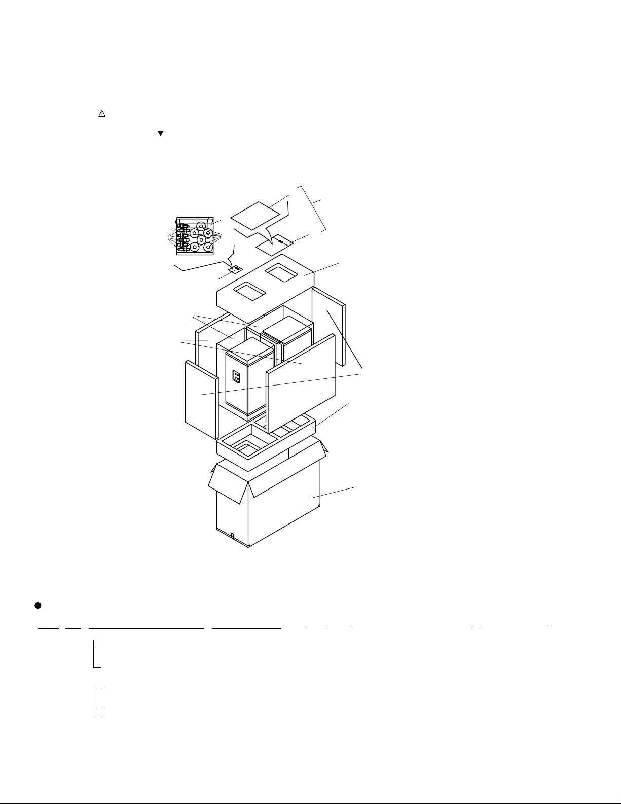
1.1 PACKING
The mark found on some component parts indicates the importance of the safety factor of the part.
•
Therefore, when replacing, be sure to use parts of identical designation.
Screws adjacent to mark on the product are used for disassembly.
•
2
1
7
5
6
3
8
4
13
10
11
9
PACKING PARTS LIST
Mark No. Description Parts No.
NSP 1 Accessories Set SME3245
2 Install Instructions SRD1233
(English,Spanish,Chinese)
3 Polyethylene Bag S2 SHL1265
NSP 4 Accessories Set SME3100
5 Spike SBA1188
6 Base SLA1052
7 Polyethylene Bag S0 SHL1259
2
12
Mark No. Description Parts No.
8 Foam Pad SHA2256
9 Foam Pad SHA2257
10 Foam Pad SHA2258
11 Foam Pad SHA2259
12 Packing Case SHG2385
13 Polyethylene Bag S7 SHL1262
Page 3
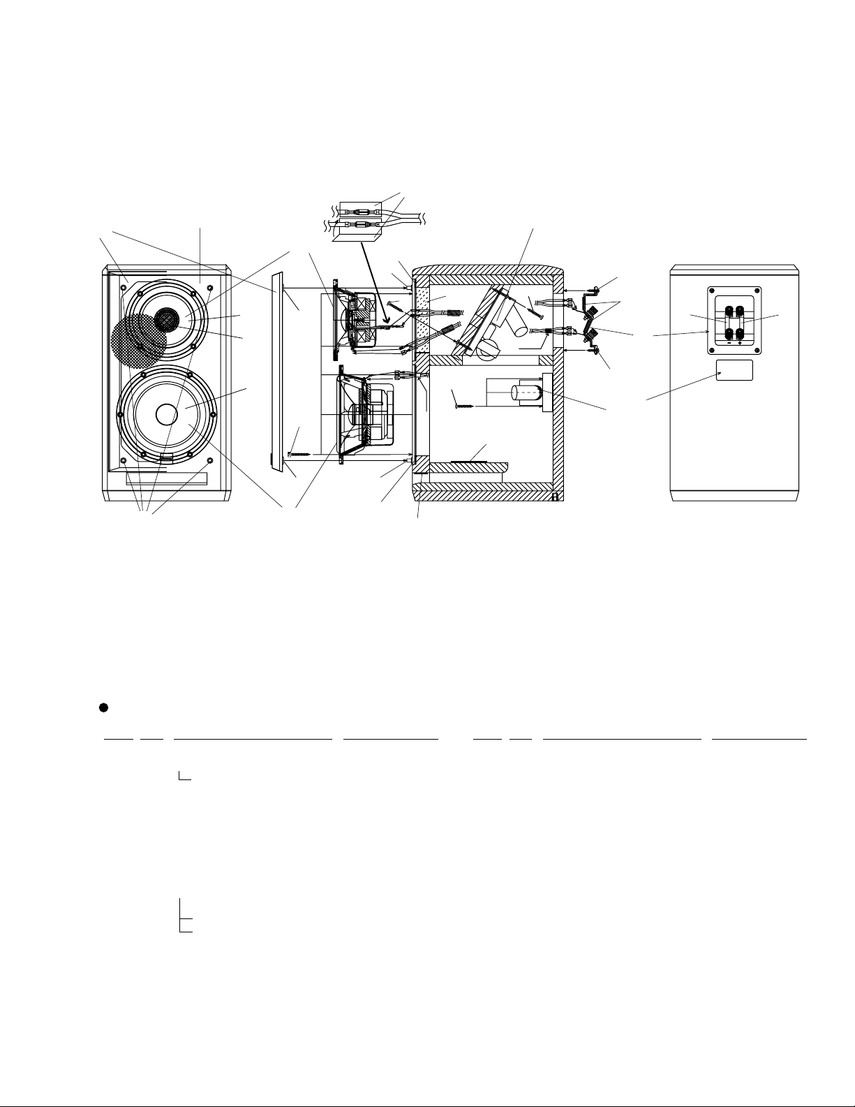
1.2 CABINET
S-A4-LR
9
2
1
15
8
13
22
Mid
19
3
Tw
Wf
16
White
18
16
Black
5
17
20
11
12
10
17
6
4
21
13
7
23
13
3
14
CABINET PARTS LIST
Mark No. Description Parts No.
NSP 1 Cabinet SMM1946
2 Grille SMG1713
3 Catch SNK2464
NSP 4 Network Assy (for Wf) SWN1649
NSP 5 Network Assy (for Mid/Tw) SWN1669
NSP 6 Model Label SAN3028
NSP 7 Gasket (for Wf) SEC1493
NSP 8 Gasket (for Mid/Tw) SEC1494
9 Gasket (for Tw cord packing) SEC1495
10 Input Terminal SKX1064
11 Conductor L SKC1065
12 Conductor R SKC1066
Mark No. Description Parts No.
13 Catch SLH1069
14 Speaker (Wf) W16FR90-51D
15 Speaker (Mid/Tw) W13FR82-51DX
16 Screw (for Network Assy) SBA1189
17 Screw
18 Screw (for Wf,Mid/Tw) SBA1191
19 Screw (for Network Assy) SBA1193
NSP 20 Damper(for Input Terminal) SEP1235
NSP 21 Damper(for Duct Board) SEP1236
NSP 22 Damper(for hole for Mid/Tw) SER1297
NSP 23 Damper(for Port) SER1299
(for Input Terminal)
SBA1190
3
Page 4

S-A4-LR
1.3 ACOUSTIC ABSOBENT ATTACHING
1
(Attach folding twice.)
5
(Attach between the No.1.)
4
(Attach on the No.5.)
5
(Attach between the Back
Board and No.4.)
9 (Attach each one piece to
left and right both sides
of the Network Assy
folding fourth.)
210
2
(Attach to the under part
of the Chamber.)
3
(Attach bending like
L shape.)
6
(Attach folding twice.)
8
(Attach to the
concave part
of Mid/Tw rear.)
(Mid/Tw Rear)
ACOUSTIC ABSORBENT ATTACHING PARTS LIST
Mark No. Description Parts No.
NSP 1 Acoustic Absorbent (200×200) SMT1109
NSP 2 Acoustic Absorbent (190×60) SMT1103
NSP 3 Acoustic Absorbent (380×130) SMT1104
NSP 4 Acoustic Absorbent (190×110) SMT1107
NSP 5 Acoustic Absorbent (160×80) SMV2015
Mark No. Description Parts No.
NSP 6 Acoustic Absorbent (250×320) SMT1112
NSP 7 Acoustic Absorbent (120×100) SMV2012
NSP 8 Acoustic Absorbent (30×30) SMT1108
NSP 9 Acoustic Absorbent (140×210) SMT1105
7 (Attach each one piece to
left and right both sides.)
(Inside chamber)
4
Page 5

S-A4-LR
1.4 NETWORK ASSY
To lower side of
the input terminal
1.4.1 LPF
[SWN1649]
6 (backside)
3
7 (bottom)
NETWORK ASSY(LPF) PARTS LIST
Mark No. Description Parts No.
1 Choke Coil 4.5 (L1) STH1236
2 Capacitor 27 (C1,C2) SCH1022
NSP 3 Circuit Board SNR1112
NSP 4 Cord SDC1013
Black Tape
4
1
2
2
White Tape
To the Woofer
5
Mark No. Description Parts No.
NSP 5 Cord SDC1015
NSP 7 Damper SER1280
6 Packing SEC1487
1.4.2 HPF
[SWN1669]
No.5 bottom
)15
5
(
8
13
(back side)
To the Tweeter
12
15
(No.6 bottom)
To upper side of
the input terminal
NETWORK ASSY(LPF) PARTS LIST
Mark No. Description Parts No.
1 Capacitor 47 (C1) SCH1023
2 Capacitor 8.2 (C2) SCE1020
3 Capacitor 3.9 (C3) SCE1021
4 Coil 3.0 (L1) STK1031
5 Coil 1.1 (L2) STK1037
7
9
No.4 bottom
14(
)
4
2
3
11
1
To the Mid
6
10
Mark No. Description Parts No.
NSP 9 Cord SDB1143
NSP 10 Cord SDD1281
NSP 11 Cord SDD1299
NSP 12 Cord SDD1278
13 Packing SEC1488
6 Coil 0.27 (L3) STK1035
7 Resistor 39 SCN1031
NSP 8 Circuit Board SNR1113
NSP 14 Damper SER1281
NSP 15 Damper SER1282
5
Page 6

S-A4-LR
2. SCHEMATIC DIAGRAM
L1
4.5mH
SWN1669
1.1mH
C1
27µF
L2
C1
47µF
C3
3.9µF
L1
3.0mH
C2
27µF
8.2µF
Clear with White
L3
0.27mH
Clear with White
C2
Red
White
Clear
R1
39
Clear
Woofer
Midrange
Tweeter
I N
Conductor
Red
Red
Black
Red
White
Black
Clear with
White
Clear
SWN1649
3. PRECAUTION OF REASSEMBLY AND DISASSEMBLY
3.1 Grille
The grille is fixed to the cabinet with catches, and it can be removed
by pulling it toward you.
When reinstalling, orient the grille with the badge at the bottom.
[Packing for the tweeter connecting cords]
3.2 Woofer
The woofer is attached to the baffle board from the outside with 6
screws.
To remove the woofer, remove the grille first and remove the screws.
To reinstall the woofer, place it so that its terminal board faces
upward.
3.3 Midrange and Tweeter
The midrange and tweeter are integrated into a coaxial unit, and the
coaxial unit is attached to the baffle board from the outside with 4
screws.
To remove this coaxial unit, remove the grille first and remove these
screws. Then remove the packing covering the cord connections of
the tweeter.
When reinstalling the coaxial unit, place the midrange so that its
terminal board faces downward. After reconnecting the tweeter
cords, cover the cord connections by using packing (two SEC1495)
to avoid short-circuiting, as illustrated at right.
Packing
SEC1495
Mid/Tw
6
Page 7

S-A4-LR
3.4 Network Assy (LPF)
The Network Assy (LPF) is attached to the inside of the rear cover of the cabinet with 4 screws from the inside.
To remove the Network Assy, first remove the grille, remove the woofer, and disconnect the cords from the woofer. Then, remove the inputterminal board by loosening the 4 screws, and disconnect the cords from the input-terminal board. Loosen the 4 screws that secure the Network
Assy, and remove it through the hole in the baffle board.
To reinstall the Network Assy, first connect the cords bundled with black tape from the Network Assy to the lower-side terminals of the inputterminal board, and the cords bundled with white tape to the woofer. Then attach the input-terminal board and the woofer. Place the inputterminal board so that the positive terminals are on the right-hand side, and attach it using the 4 screws. (See the illustration below for placement
of the Network Assy.)
[Placement of the Network Assy (LPF)]
to the lower
input terminal
Screwing
(SBA1189)
Black tape
Screwing
(SBA1189)
White tape
Upper side
to Wf
Network Assy
(LPF)
Screwing
(SBA1189)
Screwing
(SBA1189)
Lower side
3.5 Network Assy (HPF)
The Network Assy (HPF) is attached on the back of the rear board of the chamber with 2 screws(SBA1189) from the outside and 2
screws(SBA1193) from the inside of the chamber.
To remove the Network Assy, first remove the grille, remove the woofer, and disconnect the cords connected to the woofer. Then, remove the
midrange/tweeter coaxial speaker unit and disconnect the cords from the midrange and the tweeter.
When disconnecting the cords from the tweeter, first remove the packing. Then remove the input-terminal board by loosening the 4 screws, and
disconnect the cords from the input-terminal board. Pull out the Network Assy through the hole for the woofer in the baffle board.
When reinstalling the Network Assy, connect the cords by verifying the shapes of the terminals at the ends of the cords.
The cords to be connected to the input-terminal board must be connected to the upper-side terminals of the input-terminal board.
For connections with the tweeter, see 3.3. Make sure that the two cords sticking out the back of the Network Assy go through the hole in the rear
board of the chamber. Then, reinstall the input-terminal board and the woofer. Place the input-terminal board so that the positive terminals are
on the right-hand side, and attach it using the 4 screws. (See the illustration below for placement of the Network Assy and connections.)
[Placement of the Network Assy (HPF) and cord connections]
Packing
Network Assy
(HPF)
to Mid
to Tw
Screwing from Rear
(SBA1189)
Screwing from Front
(SBA1193)
Screwing from Rear
(SBA1189)
Upper side
to the upper
input terminal
Lower side
Screwing from Front
(SBA1193)
7
 Loading...