

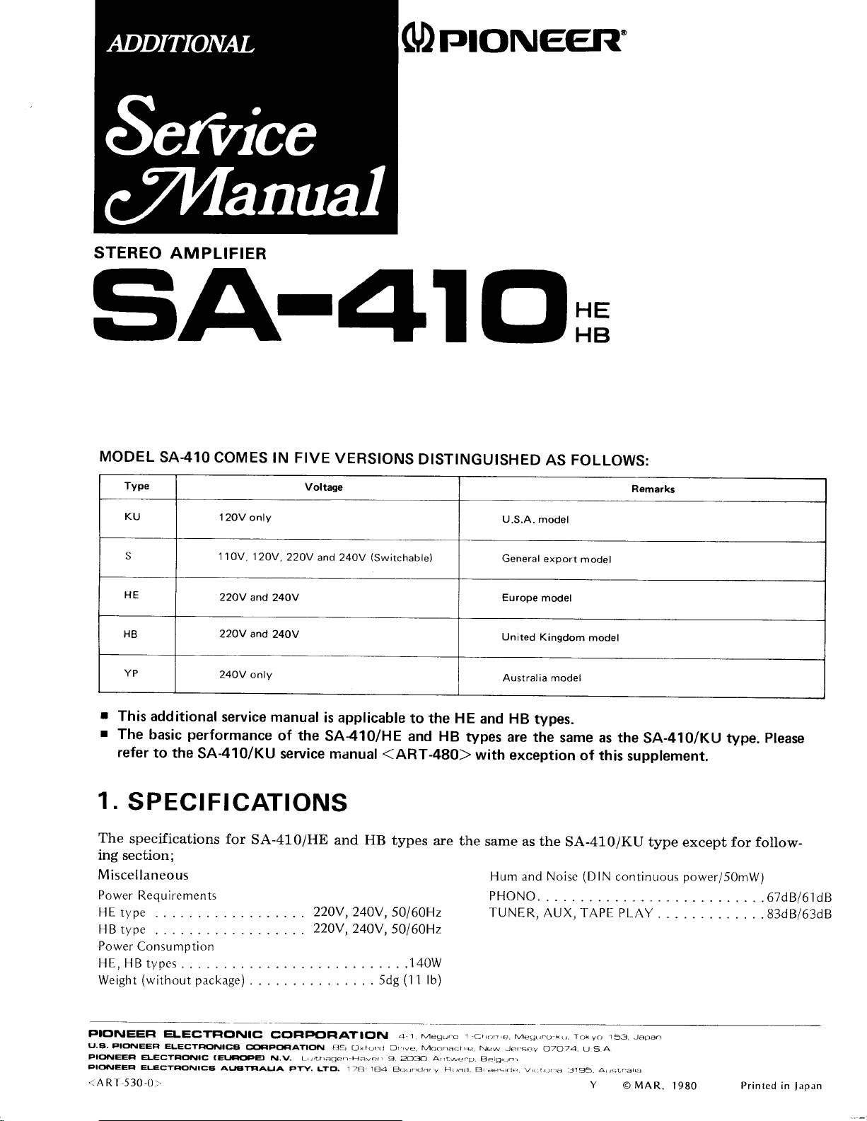
Pioneer SA-410 Service manual
STEREO
AM
PLIFIER
Stu4lOm
MODEL
r
I
1.
The
SA-410
Type
KU
S
HE
HB 22OV and
YP
This additional
The
basic
refer
to the
COMES
12OV
only
110V, 120V,22OV
22AY and
24OV
onlv
service
performance
SA-41O/KU
manual
IN FIVE
Voltage
24OY Europe
24OV
of the
service manual
SPECIFICATIONS
specifications
for
SA-41O/HE
ing section;
M
iscellaneous
Power
Requirements
HE type
220V,240V,
220V,240V,
Power
Consumption
HE,HBtypes.
Weight
(without
package)
VERSIONS
240V
(Switchable)
and
is applicable
DISTINGUISHED
to the HE
SA-410/HE and HB
<ART-480)
and HB
types
are
50l60Hz
50l60HzH B typc
.....140W
(1
1 lb)
5dg
U.S.A.
General
United
Australia model
and HB
types
are the
with
exception
the
same as the
Hum and Noise
PHONO.
TUNER,
FOLLOWS:
AS
Remarks
model
export
model
model
Kingdom
model
types.
same as
SA-410/KU
AUX, TAPE PLAY
theSA-41o/KU
of this
(DlN
supplement.
continuous
type.
type except for
power/5OmW)
.....67d8161d8
.
please
follow-
.83d8/63d8
PIONEEFI
u.8.
PICTNEEFI
rlO|\lEEFl
PIO
IEEFI
..ART
530-0r'.
FLECTFICINIC
ELECTFIOINICEI
ELECTFIONIC
ELECTFIONICg
CCIFIPTOF|ATICTN 41.Me!rL,.o i
COCIPCICIATION EJ5
(€UCrcFEt
ALTATE|ALIA
N.\/. L(rLr,agerr Haw.j.,
PTY.
LlCt.
(fxt(r.(i
17Ff 1E'4
fJ, we. Moorract,,e
g
2O3O A|r-we.p.
E!.r!rncl.r'
v
Hr)a.1.
cj,,-,r,e.Mea,,.oki,. roky.r ls3.Jarran
New Je'.s.rv
Eles,r,,rr
Bi
eres(kr wict.,)r.,a
O7074. U S A
:Jl95.
y
A(,sL.ai,.l
o MAR.
1980
Printed
in
lapan
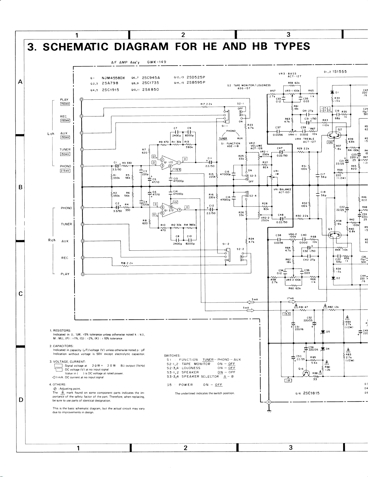
3. SCHEMATIC
DIAGRAM
AF AMP
e I NJM4558DX
2SA798
o2,3
2SC1915
PLAY
Ilsfivl
REC
F50'vl
AUX
"f
lrtfivl
TUNER
o;tl
F
t
PHONO
ct
l?.:;tl
PHONO
TUNER
AUX
AND HB TYPES
VR3: BASS
-
t?7
ACr
R59
al
ACT-02
c48
R63t
ezx
vR4
|
I
I
I
u,Bt-t
62k
-
|
VR4:
R?9
I
|
c.3? .
O OOl2
TREBLE
ACr
c.o9
:
TAPE MONITOR / t-OUOT.TESS
S 2
ASG-157
sl-l
PHONO
/\
/\
FUNCTION
SI:
ASE-II8
AUX
TUNER
VR2:
VO LU
ACT-r26
ME
VRz-I
c
o.oo-se
250h
VRI:EALANCE
c 38
?.2'
rs.|555
c43
?20
/6
-27.2
-2t
2)
f^*
R67
lo
k
-
127
R
68
R40
6.8
c25
r5p/
50(
R5
62
R5
r5
R4
to
R47
c24
22O/
25
to
ot
R5
t.5
k
R5
o/
2SD525P
2SB595P
t4
390 h
82OOp
HE
FOR
GWK-149
A$'Y
A
5
25C94
2SC1755
2SA850
R3
33O
.+
tO Rr2 30k
R
R
24OQ9
REC
L
PLAY
1. RESISTORS:
lndicated
in Q,1/oW,
(F)
:
M : MO,
2. CAPACITORS:
Indicated
in
-capacity
Indication
without voltage
3.
VOLTAGE,
CURRENT:
: DC
voltage
U
mA:
4--
4.
OTHERS
:
Adiusting
@
The I mark found
portance
of the
be sure to use
This
due to
parts
is
the
basic schematic diagram, but the actual
improvements
I
r-
t5%
(G)
t1%,
(!
(V)
point.
on some component
factor
safety
identical
of
in
tolerance unless
(K)
t2o/o,
:
F)/voltage
is
50V
no input
at
of the
designation.
desiqn.
t
:
(V)
signal
part.
10%
unless
except
Therefore,
tolerance
noted k :
otherwise
noted p :
otherwise
electrolytic capacitor.
parts
indicates
replacing,
when
may vary
circuit
the
--l
kft,
pF
im-
SWITCHES:
1 ' FUNCT ION TUNER_
S
S2-1,?,TAPE
S2-3,4:
S3-1,2
s3-3,4
,
55
MONITOR ON - OFF
LOUDNESS
SP EAKER
SPEAKER SELECTOR
POWER ON - OFF
PHONO _ AUX
ON _ OFF
-
OFF
ON
-
A
B
Q
16
2SCl8
,fi
l!lf\
R80
r.2k
l5
A
R83
?7k
|/zwl
D]
D4
D5
 Loading...