

Pioneer QX-8000 Owners manual
ij
i:r
L; f i#"
$,i
E
#
t f**
f.:i
3'
l,i
i::l
T I
€*
ft"d
ni
reffiffimfimmm"
f*
FEATURES
FOUR.CHANNEL
,,ACOUSTICAL
latest advance
The
Pioneer
channel
of
Ouadralizer
field,
sound
being in an acoustically
CHOICE OF
OUADRALIZER
FIELD
"
in sound
creates
you
giving
designed
realism:
The exclusive
an all-encompassing
full, life-like
the
concert
hall.
TWO OUADRALIZING
SYSTEMS
The Ouadralizer
stereo source
of two totally different
choice
"Matrix"
ln
creates
(Tape,
operation,
disk,
field without specified
"Phase
two-channel stereo
adds a
through the two
development
giving you
Shift"
phase-shifted
ALSO WORKS
STEREO
you
lf
the OX-8000 as a
add
PERMITS
only have
the other two
operation,
sound from
"wall
rear speakers.
preserves
that
that sensational
AS STANDARD
RECEIVER
one
regular 2-channel
speakers
4-CHANNEL
4-channel sound
FM). Moreover,
4-channel effects:
it builds
up a room-enveloping
instrument
produces
it
the front speakers,
of sound" with
An
full stereo
performance
life
pair
of speakers
at a later date.
OR
from any
it
locations. Switched
normal,
slight
exclusive,
2-CHANNEL
original
transparency
feeling.
2-CHANNEL
now,
stereo receiver and
RECORDING
you
lf
already own
using it for recording and
on
you plan
Ouadralizer's
to buy a
"quadralized"
playing
channel
back 4-channel
sound.
FULLY EOUIPPED
ILIARY CONTROLS
There are three balance
left-right balance,
complete
separate stereo headphones
are
recordings.
indicator
high and low filter switches, FM muting switch,
75O
channel mode selector.
control over
provided-important
Other
lamps,
(coaxial)
a 2-channel stereo
playback
4-channel
tape
full 4-channel capabilities,
from 2-channel source material, and
tapes
pre-recorded
WITH
AND
controls:
front-rear balance.
and
quadralized
the
for
when
features include
program
FM
indicator lamps, loudness switch,
antenna
terminals, and a 5-
tape
deck,
as before.
recorder,
you
making
tapes with
4.CHANNEL
INPUTS
left-right balance,
front
sound
front
the
monitoring
and
"speakers
These
4-channel
in operation"
CREATES
four-
sensation
EFFECT
2-channel
gives you
sound
transparent
and then
echo effect
Pioneer
while
you
can use
TAPE
you
can
However, if
can use the
your
own
true 4-
AUX.
rear
you
give
field. Also.
rear channels
tape
300S1 and
position
VERSATILE
FACILITIES
2-channel
4-channel
2-channel
mal
4-channel
CIRCUIT
a
rer.eoEIpPED
The
improve
to
employs
numerous
tuner's
works
cellent
FM dial
tuning
BUILT.IN
Sensitive
required in most cases.
not
LOW-D
AMPLI
Both
generous
go
quency
is a
construction.
ALL
SIGN
Cabinet
Pioneer
square
control
color
TAPE-TO-TAPE
tapes can be
stereo
(by
tape
deck
tape-to-tape
tape-to-tape dupl
using the
quadralized
preamplif
dubbing
icating.
DUPLICATING
and dubbed
outputs).
ier
possible
is
too, as well
CONSTRUCTION
FM TUNER
FM tuner
is
equipped
selectivity and sensitivity. Also,
hybrid and
one
transistors, ceramic
sensitivity and selectivity. The
according to
channel separation. Tuning is made easy by
and the
meters.
the
double
with an FET in its
the lF stage
monolithic lC, replacing
one
filters, etc., and raising
FM MPX decoder
time switching system and boasts
(signal
strength and center
AM FERRITE BAR ANTENNA
highly
and
directional. An outdoor
ISTORT ION, HIGH-POWER AUDIO
FI ER
tone controls and equalization amplifier
amount of
response accuracy
quasi-complementary
NEW
"OUADRALIZED"
control
and
"Ouadralizer"
tuning dial, a modernistic and logically
panel,
styling.
negative feedback for improved
and flatness. The
design, a tried-and-true
panels
are visual symbolizations
concept, with a
and the famous silver-black-wood
AM antenna is
operate with
power
EXTERIOR
recessed, framed,
onto
Nor-
front end to
the
ex-
the linear
zero)
fre-
amplifier
circuit
DE-
of the
arranged
Pioneer
a
as
a
TJIONEEFI
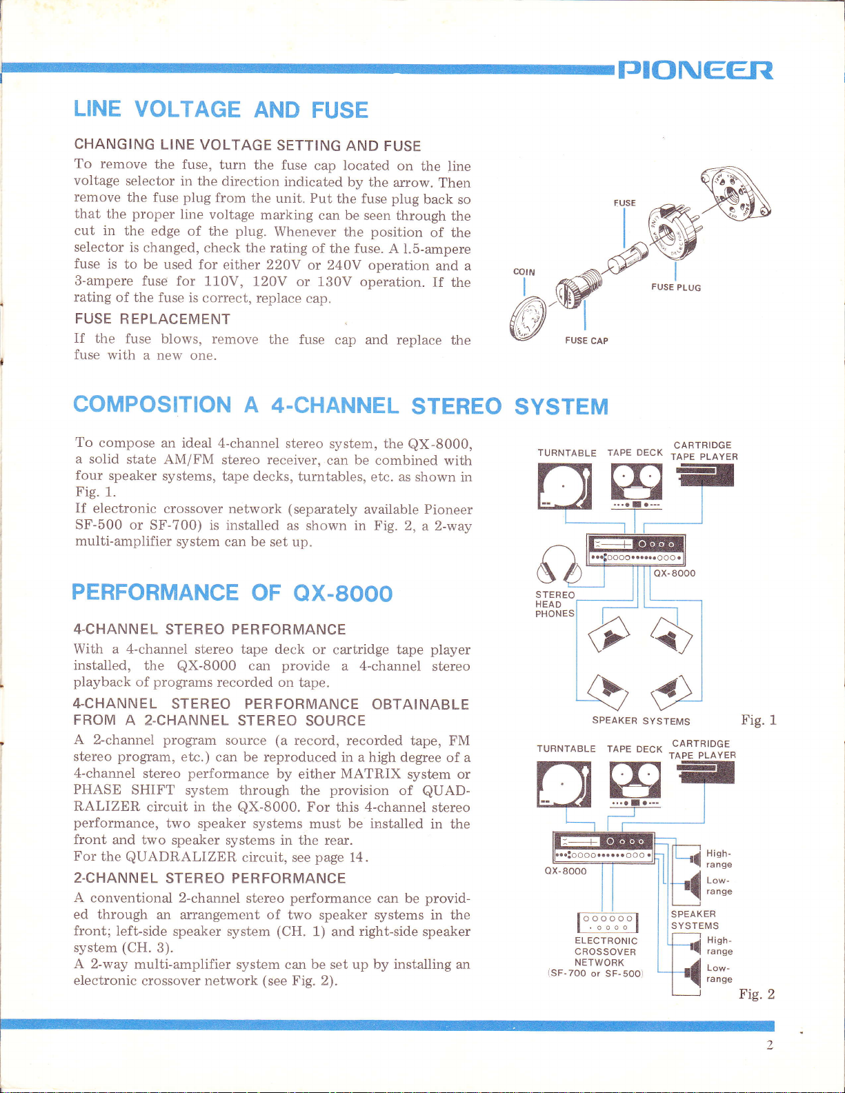
LINE
CHANGING
To
voltage
remove
that
cut in
selector
fuse
S-ampere
rating
FUSE
If
fuse
VOLTAGE
LINE VOLTAGE
remove
the
is
the fuse
with a new
the fuse,
selector
the
fuse
proper
the
edge of the
is
changed,
to be
used for
fuse
of the
fuse is
REPLACEMENT
blows, remove
turn
in the
direction
plug
from the
line
voltage marking
check the rating
either 220Y
for 110V,
correct, replace
one.
COMPOSITION
To
compose
a solid
four
Fig.
If
SF-500
state AM/FM
speaker
1.
electronic
or SF-700)
multiamplifier
an ideal
systems,
crossover
system
4-channel
stereo receiver,
tape decks,
network
installed
is
can be set
AND
the fuse
FUSE
SETTING
cap located
indicated
unit. Put
can be seen
plug.
Whenever
of
or 240V operation
120V
A
or 130V operation.
cap.
the
fuse
4-CHANNEL
stereo
can
turntables,
(separately
as shown in Fig.
up.
AND
FUSE
on
the
by the
the fuse plug
the
the fuse. A
arrow.
back
through
position
1.5-ampere
cap and replace
STEREO SYSTEM
system, the
be
available
QX-8000,
combined
etc. as shown
Pioneer
2,
a 2-way
line
Then
of
and a
if
with
so
the
the
the
the
TURNTABLE TAPE DECK
in
CARTRIDGE
TAPE PLAYER
PERFORMANCE
4-CHANNEL
With
a
installed,
playback
4-CHANNEL
FROM
A 2-channel
stereo
4-channel
PHASE
RALIZER
performance,
front
For
2-CHANNEL
A conventional 2-channel
ed through
front; left-side
system
A 2-way
electronic
program,
and two
the
(CH.
STEREO PERFORMANCE
4-channel
the
programs
of
stereo tape deck
QX-8000
recorded on
STEREO
A 2-CHANNEL
program
etc.) can be reproduced in a high
stereo
SHIFT
performance
system through
circuit
in the
STEREO
source
QX-8000.
two speaker
speaker systems in the rear.
QUADRALIZER
STEREO PERFORMANCE
an arrangement of
speaker
3).
multi-amplifier system
crossover
system
network
OF
QX.SOOO
or
cadridge
provide
can
tape.
a 4-channel
PERFORMANCE
SOURCE
(a
record, recorded
by either
the
MATRIX
provision
tape
OBTAINABLE
For this 4-channel
systems must be installed
circuit, see
stereo
page
14.
performance
can be
two speaker systems in the
(CH.
(see
1) and
be set up by installing an
can
Fig. 2).
right-side
player
stereo
tape, FM
degree of a
system or
of
QUAD-
stereo
in the
provid-
speaker
SPEAKER
TURNTABLE TAPE
ELECTRONIC
CROSSOVER
NETWORK
(SF-7OO
or SF-5OO)
SYSTEMS
DECK
CARTRIDGE
PLAYER
TAPE
Fig.
Fig.
1
2
INSTALLATION
The
fully-transistorized
installing
.
o
.
A
The
and
ceiling and
harsh
reflecting
improved
(especially
On
"soak
Furniture
the
two
corrected
reducing
it,
however,
place
The
dampness
The
unit should
sun.
place
The
surface
should
WORD
quality
shape of
or
the other
sound.
speaker
of reproduced
the
"bright"
surfaces,
by
that facing
up"
the sound,
may
In
by angling
the
distance
check the
should
and
dust.
not
should
be free from
be level
ABOUT
the room,
amount
a sound
and/or
having
hand,
be rearranged
any
systems
ample
the speakers)
too
event,
are
between
QX-8000
generates
following points:
be well-ventilated,
be
exposed
and stable.
to the direct
significant
ROOM
sound
the
and arrangement
usually results
too
many
resulting
the true
placed
them
materials
low a
carpet
absorbing
provide
to
too far
slightly
them.
varies
ceiling. This
area or
with a thick
in a
irregular
stereo
toward
no
heat.
When
and
free
from
rays
of the
vibration,
or the
ACOUSTICS
according
of walls,
of
from
covering
surfaces
certain
effect is
apart.
to the
floor
furniture.
too
many hard
condition
the
curtain.
will
tend
"deadness"
reflection
lost
This
may be
each
other or
if the
size
and
Too
is
wal
to
of
TJIONEEFT
SPEAKER
TO
SPEAKER
For
systems
ways:
2
3
4
Since
designed
illustrated
NOTES: 1.
SPEAKER
For
use four
Since
that
1. Select
2.
CONNECTION
1.
2.
D.
SPEAKER
SYSTEM
an
optimum
can
-
2
system:
-
l
system:
-
0 system:
the
for
in Fig.
Front left
Front right
Rear
Rear
For a better 4-channel
speaker
than the listening position.
2.
When listening
speaker
SYSTEMS
the
best
speaker
it
is difficult
speaker
two
teristics,
select
tics
Connect
plug
(+)
negative (-)
that
Connect
speaker
panel.
RIGHT (CH.
Connect
speaker
speaker
to
two
compared
as
shown
lead
all
connections
system
Likewise,
system
plug
the
socket
be
Two
front
Three
front
All
front.
QUADRALIZER
2
left
right
4-channel
systems
and
speaker
the
leads
to
the
lead
the
the
SYSTEM POSITIONS
SYSTEMS
ARRANGEMENTS
4-channel
arranged
speaker
and
speaker
and
four
speaker
-
2
system,
3.
Channel
-
Channel 3
-
Channel 2
-
Channel
-
systems in the
to
systems
as suggested
stereo
systems
to
meet this
be
selected
speaker
arrange
them
system
with the
from
in Fig.
4. Make
positive
to
the
are
speaker plug
to the
connect
3) speaker
speaker plug
to the
for
REAR
CH.
4.
stereo performance,
in
the
following
two
one
systems
speaker
systems
speaker
are
systems
system
systems
circuit
install
a 4-channel
having
systems
in the
front
the
terminal
negative
correct.
speaker
the
system
speaker
RIGHT
four
1
4
stereophonic
rear
be installed
program
for
that
performance,
the
requirement,
and
arranged
having
front.
having
speaker
as
speaker
system
sure
to
of
terminal.
for
FRONT
socket
speaker plug
to
the socket
for
REAR LEFT
socket
(CH.
positioned
positioned
are
in the
positioned
are
of
the
speaker
effect, it is
on a level
source,
particular
it is
same
as follows:
the same
identicar
systems
connect
the
LEFT (CH.
CH.
CH.
4)
speaker
three
in
the rear.
rear.
eX-8000
systems
suggested
arrange
program.
desirable
characteristics.
it
is suggested
characteris-
as
to
the
the
plug,
Then,
1 on
for
CH.
2,
speaker
different
in
in
in
a little
higher
the four
charac-
possible.
speaker
positive
and
confirm
the
rear
FRONT
g.
(CH.
and
system
AND
the
the
the
ts
AS
that
to
the
1)
2)
the
CONNECTIO
FRONT
(LEFT
RE'AF:
LE.FT
{LEFT.SPEAKER)
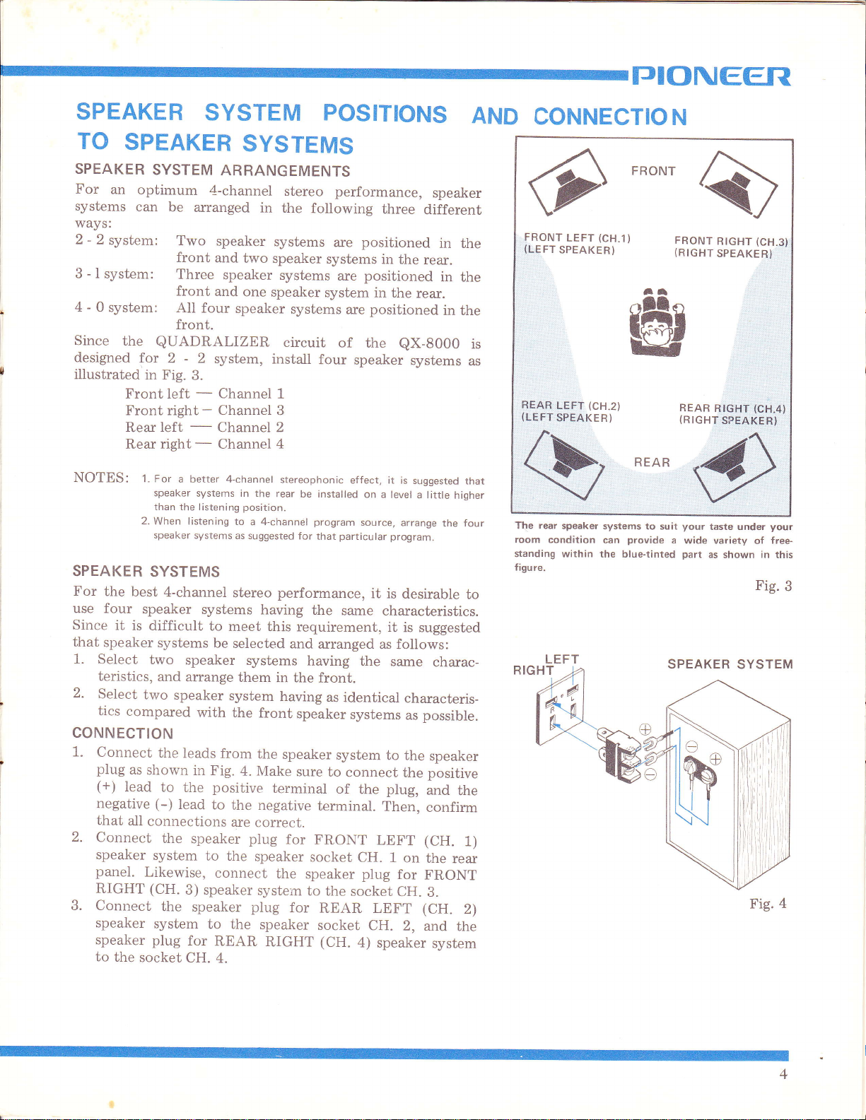
The rear
room
condition
standing within
figure.
(CH.1)
LEFT
SPEAKER)
(CH.2)
speaker systems
can
the blue-tinted
N
FRONT
FRONT
(RIGHT
at
r@
pg4p
(RIGHT.SIq,EAKEEJ
REAR
your
to suit
provide
a
wide variety
part
SPEAKER SYSTEM
RIGHT
SPEAKER}
9161,11,:1c9
taste under
as shown
Fig.
(CH-3}
..:
a|
your
free-
of
in
this
Fig.3
4
.'
 Loading...