

Pioneer QX-646 Owners manual
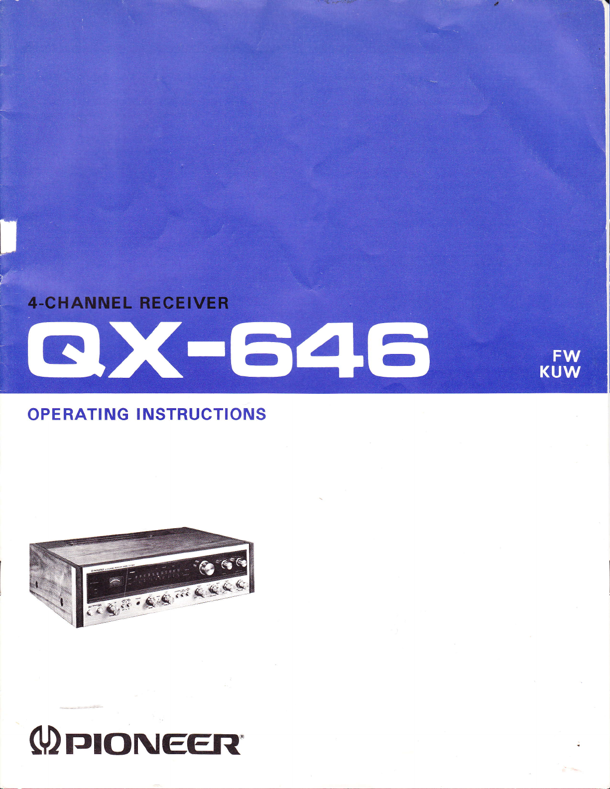
OPERATING
INSTRUCTIONS
(Dr:roNEEFl'
Thank
a Pioneer
solid state receiver
of 4-channel
tapes or
SQ matrix records
speaker
you
for the
4-channel receiver,
sound in all
records
disc
systems at the
confidence
lead
will
its varieties:
(CD-4),
and
broadcasts. lf
moment, the
shown us in
model
QX-646.
you
into
regular
purchasing
This
the exciting
discrete 4-channel
(RM)
matrix
you
only
QX-646
will
4-channel
world
as well as
have
two
also
serve
as a 2-channel receiver
4-channel sound by adding
To develop its
bined with other components
of equally
deck)
lowing
this receiver's
operating
full
many
until
two more speaker
potentials,
quality.
high
instructions carefully
possibilities
you
decide to
the
QX-646
(speakers,
please
Also,
to make full use of
and features.
step up into
systems.
must be com-
turntable,
study the fol-
tape
LINE VOLTAGE
The
QX-646
operates
one
of the five line voltages;
220Y
and 240V.
your
If
proper
the
described below.
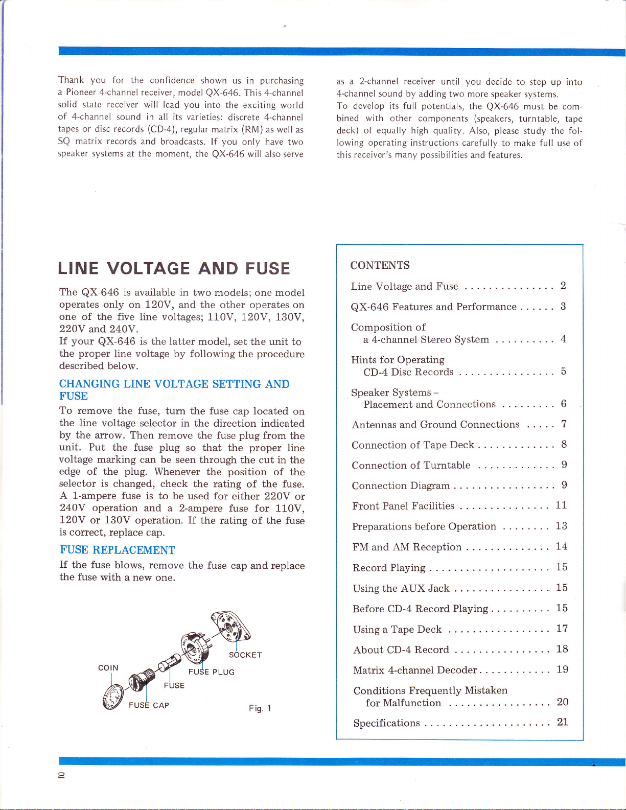
CHANGING LINE
FUSE
To remove
the line
by the arrow.
unit. Put
voltage
edge
of the
selector is
A l-ampere
240V
120V
is correct,
FUSE
If
the fuse
operation
or 130V
REPLACEMENT
the fuse
is
available
only on L20V,
is
latter
QX-646
line voltage
the
by following
VOLTAGE SETTING AND
the fuse, turn
voltage selector in
Then remove
the fuse
marking
plug.
changed, check
fuse is
replace
blows, remove
with a new one.
plug
can be seen
Whenever
to be used for
and
a 2-ampere fuse
operation.
cap.
in
and the other operates on
so that
AND FUSE
two models; one model
110V, 1,20V,130V,
model, set
the
fuse
the
the
the
cap located
direction
fuse
the
through the cut in
position
the
the rating
either 220Y
If
the
rating of the
the fuse
cap and replace
the
procedure
indicated
plug
from
proper
the fuse.
of
for 110V,
unit
of
to
on
the
line
the
the
or
fuse
CONTENTS
LineVoltageandFuse
QX-646
Composition
Features
of
a4-channelStereoSystem
for Operating
Hints
Performance
and
CD-4DiscRecords
Speaker
Antennas
Systems
PlacementandConnections
and
-
Ground Connections
.
ConnectionofTapeDeck.
Connectionof
Turntable
ConnectionDiagram
...
.......
FrontPanelFacilities..
PreparationsbeforeOperation
FMandAMReception..
RecordPlaying
UsingtheAUXJack.
....2
. . . 3
. . .
.....
......5
...
. . . . . 7
......
.....9
...11
...
..74
.....15
.....15
4
6
8
9
13
BeforeCD-4RecordPlaying
... . .
15
6a
......
......
......
.....20
"b-qffiw:
UsingaTapeDeck.
AboutCD-4Record
Matrix4-channelDecoder
Conditions
forMalfunction
Frequently
....
Mistaken
.
Specifications...
2
L7
18
19
..2L
TJIONE€R
OX.646
Combines
in
One Unit
Exciting
varieties;
tape,
an exclusive
4-channel sound is
discrete 4-channel
discrete 4-channel
FEATURES
All Current
phono
SQ matrix records
Extracts
Sources
The built-in
2-channel
wrap-around
sound
giving your
sound.
2-channel
Accepts
The
rear
can
possible
ments in the
program
Versatile
The
including speaker
switches, a tape
monitoring
2-channel
FET-equipped
The FM
improve
employs
numerous
tuner's
works
excellent
linear
Built-in
Sensitive
not
4-channel
"regular
program
4-channel sound, bringing to life
components found in
present
(lf you
wish,
stereo fashion, too.)
2 Pairs
QX-646
speakers, for a total of
be turned
can drive one
on and off with
to
have two different
listening room and to
souces or
Auxiliary
QX-646
according
FM dial
is fully equipped
the front
as well
as 4-channel tape
FM Tuner
tuner is equipped
selectivity
one hybrid dnd
transistors,
sensitivity and
to the time
channel
and the signal meter.
AM Ferrite
and highly directional.
required
in most
4-channel
yours
System
in all four of
from open-reel and
RM
(CO-+
Oisc record with
(regular
matrix) and
disc record
cartridge),
and broadcasts.
Sound from
2-channel Program
matrix" circuit can convert
sources
of Rear
personal preferences.
(records,
stereo LPs a totally new and
you
can
Speakers
pair
six speakers. The rear speakers
tapes, FM
practically
play
any record, and
them
in conventional
of front plus
push-button.
a
4-channel speaker
select one according
two
This makes it
Circuits and Control
with auxiliary controls
on/off and rear speaker
monitor switch, a headphone
channels only), and terminals
equipment.
with an FET
and sensitivity.
one
ceramic filters,
selectivity.
switching system and
separation. Tuning is
Bar Antenna
cases.
'Also,
monolithic lC, replacing
etc., and raising the
The
An outdoor
A/B selector
front end
in its
the lF
FM
MPX
made easy by the
AM antenna is
its current
cartridge
regular
stereo)
the echo
exciting
pairs
arrange-
jack
stage
decoder
boasts
into
(for
for
of
to
to
Low-distortion Audio Amplifier
Both tone controls and
improved
power amplifier
and-true
Looks
To
be
whose
performance
is easier
complete
according
in a natural
frequency
circuit
as lmpressive as lt
response accuracy and flatness
quasi-complementary
is a
construction.
this 4-channel receiver
applied
it is a rather large, impressive looking unit
-
outward appearance
and versatility. The dial
to read.
with
to
walnut cabinet.
Your operation becomes much
program
the
desired
operation, and the unit comes installed
equalizatlon
Sounds
the
already hints at its superb
and mode indicator lighting
amplifier operate
design, a
word "compact"
and
PE RFORMANCE
4-Channel
With a 4-channel stereo
player
channel
tion,
record with a stereo
CD-4
4-channel Reproduction from Matrix
Source
The
production
broadcasts. The mode switch has
matrix
take either
to
Matrix Reproduction
A 2-channel
can be
matrix
SQ
ment
2-channel Stereo Performance
Conventional
through
front; left-side speaker system and right-side
tem.
Stereo Performance
installed,
playback
the
QX-646
phono
self-contained
and
reproduced
the
QX-646
programs
of
can reproduce a
turntable equipped
cartridge.
matrix circuit
from
matrix 4-channel records or
matrix
SQ
these
of
signal
forms.
from
in 4-channel form
circuit. ln this case, the
over ordinary
an
2-channel stereo reproduction.
2-channel stereo
arrangement or two speaker systems
tape
deck or cartridge tape
provide
can
recorded
on tape. ln addi-
discrete 4-channel disc
with an exclusive
4-channel
permits
positions
reproduction, allowing
from
2-channel
record or
a
Stereo Source
FM stereo
via the regular
result is an improve-
performance
can be
for
fhe
T
ied-
tri t
can not
section
meter
easier,
a
discrete 4-
4-channel re-
FM stereo
for
regular
reproduction
broadcast
provided
in the
speaker sys-
up
or
3
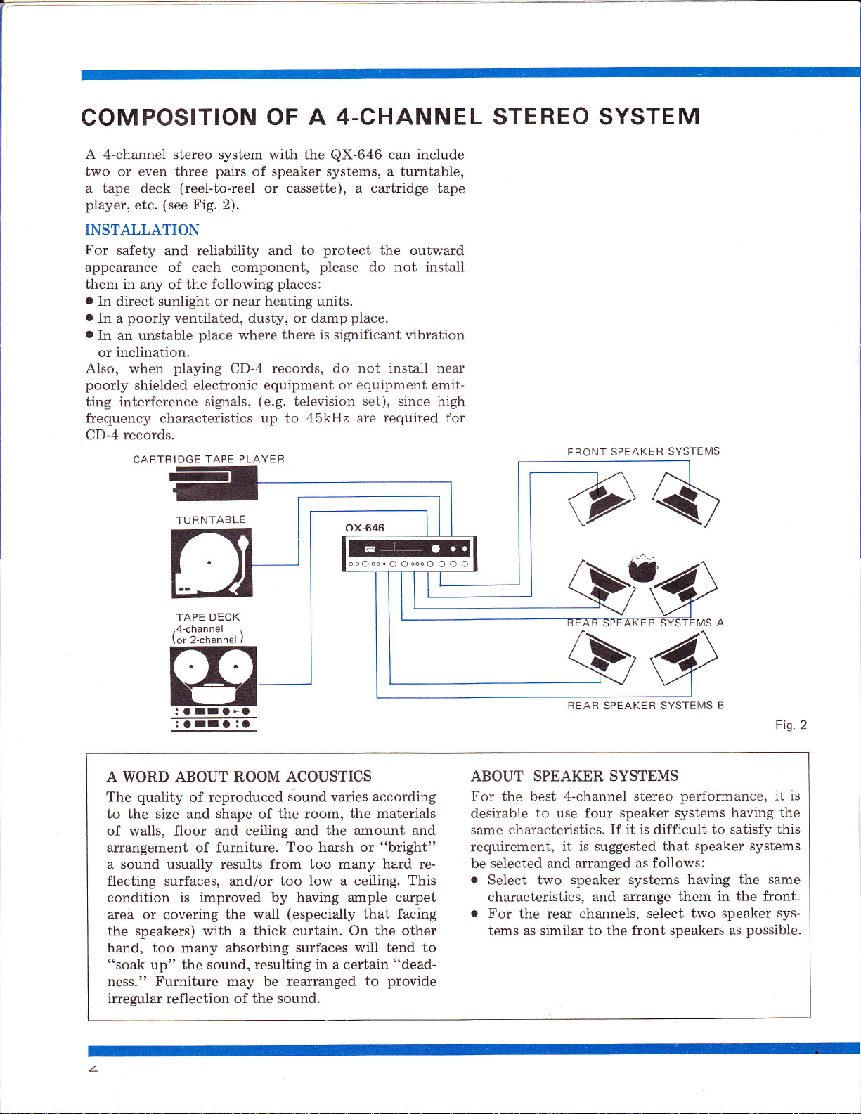
4-CHANNEL STEREO SYSTEM
COMPOSITION OF
A
4-channel stereo system with the
two or even
a tape deck
player,
etc.
(see
pairs
three
(reel-to-reel
Fig. 2).
of
or cassette),
A
QX-646
speaker systems, a turntable,
a cartridge
INSTALLATION
For
safety
appearance of each component,
them in
.
In
direct sunlight or near
.
In
a
.
In an unstable
or inclination.
Also, when
poorly
interference signals,
ting
and reliability
any of the
poorly
following
ventilated, dusty,
place
playing
shielded electronic
and to
places:
heating units.
where
records,
CD-4
equipment or equipment emit-
(e.9.
protect
please
damp
do
place.
not install near
or
there is significant vibration
television
frequency characteristics up to 45kHz are
CD-4 records.
CARTRIDGE TAPE
PLAYER
can include
tape
the
outward
do not install
set), since
required for
high
FRONT
SPEAKER
SYSTEMS
TU R NTAB
TAPE
4-channel
or 2-channel )
A WORD ABOUT ROOM
quality
The
of reproduced
to the size and shape of the room,
of walls, floor
arrangement of furniture.
sound
a
flecting surfaces, and/or too
usually
LE
DECK
ACOUSTICS
ox-646
iound varies
and ceiling and
the amount and
Too harsh or
results from too many
low
a
according
the materials
"bright"
ceiling. This
condition is improved by having ample
area or covering the wall
speakers)
the
hand, too
"soak
ness."
irregular
up"
Furniture
reflection
many
the
a thick curtain. On
with
absorbing
sound,
resulting
may be
of the sound.
(especially
surfaces will tend to
in a certain
rearranged to
that facing
the
hard
carpet
other
"dead-
provide
re-
REAR SPEAKER
SYSTEIVIS
ABOUT SPEAKER SYSTEMS
For the best 4-channel
desirable
same
requirement,
selected
be
o
Select two speaker
characteristics, and arrange
o
For
tems as
to use four
characteristics. if it is difficult
it is suggested
and arranged
the rear channels,
similar to the front
stereo
speaker systems having
that speaker
as follows:
systems having the
select two
B
performance, it is
to satisfy this
systems
in the front.
them
speaker
speakers as
possible.
Fig.2
the
same
sys-
PION€EIT
HINTS
TURNTABLE
The CD-4
signals
45kHz.
the recording level is
note
take
CD-4 disc record reproduction
o
The PHONO
vibrations, revolve at constant rotational speed with-
out wow
to-noise ratio.
.
The
is, can
it
must
to adjust the tonearm so that the tracking
be distributed
of the record
PHONO
To
effectively reproduce the wide
CD-4 records
record
disc
Make
phono
down vertically onto the record surface when
cartridge
remain the
FOR
disc
based on a
Compared to conventional 2-channel disc records,
OPERATING
record
is engraved by high
30kHz
carrier, which extends up to
CD-4 DISC
frequency
low. Therefore, it is desirable to
of the following suggestions connecting the
tumtable.
MOTOR must operate almost
flutter, and
and
TONEARM must have sufficient trackability,
track the
have
CARTRIDGE
reproduction to use an exclusive cartridge.
groove
an anti-skating device and
equally
groove.
over a
long
certain that the stylus is in
cartridge is
is replaced,
same as before.
installed,
so
produce
with
light
an excellent
tracking
lateral balance
to both the left and
frequency range
period,
that separation and sound
it is
essential
position
and that the
without
force.
force can
right
for
when the
stylus
the
RECORDS
signal-
that
Also
walls
of
CD-4
goes
phono
quality
RECORD
Since the
engraved, even
pleasant
can scratch
Since the warped
it is
Before
with high
be washed
STYLUS
If dust clings
become
and the disc is
The stylus
playing
HANDLING
groove
noise
the record
desirable
and after
quality
with water.
CLEANING
poor,
must always be cleaned
is
over. If
of the CD-4
a small amount of
poor
and
disc
to exercise utmost care in handling them.
playing
cleaner, not a
to the stylus, sound
4-channel stereo is impossible to reproduce,
damaged.
dust
fully with commercial
record is delicately
disc
can cause un-
dust
sound
surface, reducing its service life.
record
the
is difficult
available alcohol stylus cleaner.
quality.
is never reproduced exactly,
disc,
spray-type.
quality
to
In addition, it
it
should
be cleaned
It must not
and separation
whenever
remove, clean care-
a record
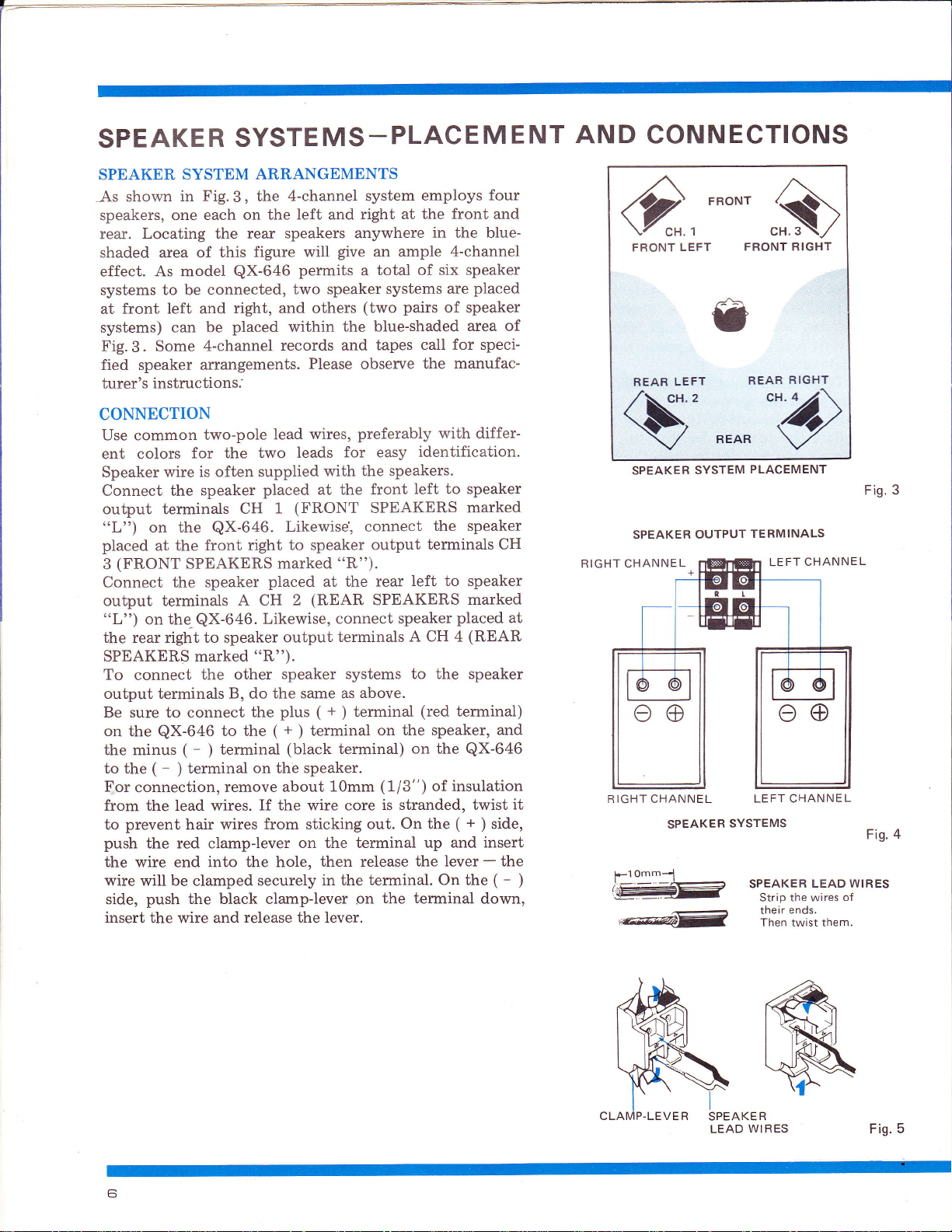
SPEAKER
SYSTEMS-PLACEMENT
AND
CONNECTIONS
SPEAKER SYSTEM
Fig.
As shown
speakers, one
rear.
shaded area of
in
each on the
Locating the rear
effect. As model
systems to be
front left and
at
systems)
Fig.3.
fied speaker
turer's instructions.'
CONNECTION
Use common
ent colors
Speaker wire
Connect the
can be
4-channel
Some
ailangements.
two-pole
for the
is often supplied
speaker
output terminals
on the
"L")
placed
(FRONT
3
at the
front
SPEAKERS marked
Connect the speaker
output terminals
on the,QX-646.
"L")
the rear right to speaker
SPEAKERS marked "R").
To
connect
the
output terminals
Be
on
the minus
to the
For
to
sure
the
connection,
connect
QX-646
(
-
(
terminal
-
)
from the lead wires.
prevent
to
push
hair
the red clamp-lever
the wire end into the hole,
wire will be clamped securely
push the black clamp-lever
side,
insert the wire and release the lever.
ARRANGEMENTS
4-channel system
the
3,
left and
speakers anywhere
figure will
this
QX-646
connected,
right, and
placed
permits
two speaker
others
within
records and
Please
wires,
lead
two leads
with the
placed at the
(FRONT
1
CH
QX-646.
Likewise, connect
right to speaker
placed
A CH
Likewise, connect
(REAR
2
at the
output
other
B,
to the
terminal
)
remove about
speaker systems to the speaker
the same as
do
+
(
plus
the
+
(
terminal
)
(black
on the speaker.
If the wire core
wires from sticking
on the terminal
then release
in the terminal.
1Omm
employs
right at the
give
an ample
total
a
systems
(two pairs
front
in
the blue-
4-channel
of six speaker
are
of speaker
the blue-shaded
call for speci-
tapes
manufac-
observe
preferably with differ-
for easy
front
SPEAKERS
the
identification'
speakers.
left to speaker
the speaker
output
terminals CH
"R").
Ieft to speaker
rear
SPEAKERS
(red
placed
terminal)
terminals
above.
terminal
)
speaker
A CH 4
on the speaker,
terminal)
on the
(1/3")
is stranded, twist
On
out.
QX-646
of insulation
+
(
the
up and insert
the lever
On the
the terminal
on
four
and
placed
area of
marked
marked
(REAR
and
side,
)
the
-
(
-
down,
at
SPEAKER
SPEAKER
RIGHT CHANNEL
it
)
RIGHT CHANNEL
SYSTEM
OUTPUT
SPEAKER
"w=
PLACEMENT
TE RMINALS
LEFT CHANNEL
SYSTEMS
SPEAKER
Strip the wires
their
Then twist
LEAD WIRES
ends.
them.
Fig.3
4
Fig.
of
SPEAKE
LEAD
R
WIRES
Fig.
5
 Loading...